EP4307818A2 - Neue dci-formate für nicht-anker-operationen - Google Patents
Neue dci-formate für nicht-anker-operationen Download PDFInfo
- Publication number
- EP4307818A2 EP4307818A2 EP23213230.8A EP23213230A EP4307818A2 EP 4307818 A2 EP4307818 A2 EP 4307818A2 EP 23213230 A EP23213230 A EP 23213230A EP 4307818 A2 EP4307818 A2 EP 4307818A2
- Authority
- EP
- European Patent Office
- Prior art keywords
- random access
- carrier
- wireless device
- carriers
- network node
- Prior art date
- Legal status (The legal status is an assumption and is not a legal conclusion. Google has not performed a legal analysis and makes no representation as to the accuracy of the status listed.)
- Withdrawn
Links
Images


Classifications
-
- H—ELECTRICITY
- H04—ELECTRIC COMMUNICATION TECHNIQUE
- H04W—WIRELESS COMMUNICATION NETWORKS
- H04W74/00—Wireless channel access
- H04W74/002—Transmission of channel access control information
- H04W74/006—Transmission of channel access control information in the downlink, i.e. towards the terminal
-
- H—ELECTRICITY
- H04—ELECTRIC COMMUNICATION TECHNIQUE
- H04W—WIRELESS COMMUNICATION NETWORKS
- H04W74/00—Wireless channel access
- H04W74/002—Transmission of channel access control information
-
- H—ELECTRICITY
- H04—ELECTRIC COMMUNICATION TECHNIQUE
- H04W—WIRELESS COMMUNICATION NETWORKS
- H04W74/00—Wireless channel access
- H04W74/08—Non-scheduled access, e.g. ALOHA
- H04W74/0833—Random access procedures, e.g. with 4-step access
-
- Y—GENERAL TAGGING OF NEW TECHNOLOGICAL DEVELOPMENTS; GENERAL TAGGING OF CROSS-SECTIONAL TECHNOLOGIES SPANNING OVER SEVERAL SECTIONS OF THE IPC; TECHNICAL SUBJECTS COVERED BY FORMER USPC CROSS-REFERENCE ART COLLECTIONS [XRACs] AND DIGESTS
- Y02—TECHNOLOGIES OR APPLICATIONS FOR MITIGATION OR ADAPTATION AGAINST CLIMATE CHANGE
- Y02D—CLIMATE CHANGE MITIGATION TECHNOLOGIES IN INFORMATION AND COMMUNICATION TECHNOLOGIES [ICT], I.E. INFORMATION AND COMMUNICATION TECHNOLOGIES AIMING AT THE REDUCTION OF THEIR OWN ENERGY USE
- Y02D30/00—Reducing energy consumption in communication networks
- Y02D30/70—Reducing energy consumption in communication networks in wireless communication networks
Definitions
- Certain embodiments of the present disclosure relate, in general, to wireless communications and, more particularly, to new downlink control information (DCI) formats for non-anchor operations.
- DCI downlink control information
- Machine Type Communication generally refers to devices that communicate without human interaction, i.e., devices built into machines. MTC is part of the even more general discussion of Internet of things (IoT), where it is envisioned that all devices that can benefit from being connected will be connected. Predictions for coming years point toward there being a very large number of MTC devices. Many of these devices such as narrowband IoT (NB-IoT) devices will probably be fairly stationary, e.g., the device is located in a vending machine and perhaps even built into walls. These devices are meant to last many years and operate without chargers. For example, the NB-IoT system which is based on existing LTE systems and addresses optimized network architecture and improved indoor coverage for massive number of devices is designed for following characteristics:
- each cell ( ⁇ 1 km 2 ) in this system will serve many thousand devices such as sensors, meters, actuators, and the like.
- NB-IoT technology e.g., 180 KHz bandwidth, same as one LTE Physical Resource Block (PRB)
- NB-IoT For FDD mode of NB-IoT (i.e., the transmitter and the receiver operate at different carrier frequencies) only half-duplex mode needs to be supported in the UE. In order to achieve improved coverage, data repetition is used both in uplink (UL) and/or downlink (DL).
- the lower complexity of the devices e.g., only one transmission/receiver chain
- UE user equipment
- the working assumption is to have cross-subframe scheduling. That is, a transmission is first scheduled on a Physical DL Control Channel (NPDCCH) and then the first transmission of the actual data on the Physical DL Shared Channel (NPDSCH) is carried out after the final transmission of the NPDCCH.
- NPDCCH Physical DL Control Channel
- NPDSCH Physical DL Shared Channel
- NB-IoT not all the subframes are available for dedicated data communication in DL in an NB-IoT cell.
- the amount of available subframes in the DL is dependent on one of the three operation modes (i.e., Stand-alone, In-band, and Guard-band) NB-IoT is deployed in.
- a UE needs to rate-match around the following non-available subframes (or parts of subframe):
- NB-IoT Due to the nature of NB-IoT with half-duplex communication, cross-subframe scheduling, low bandwidth, the available amount of subframes, and the amount of UEs to be served, it becomes evident that, as all other communication systems, NB-IoT will naturally benefit from utilizing more spectrum for efficient operation, especially if such spectrum is already available (e.g., in an in-band operation mode during low traffic hours when LTE carrier is not fully used). Therefore, in 3GPP Rel-13, NB-IoT multi-carrier operation has been adopted where the UE operating in an NB-IoT anchor carrier is configured through higher layer signaling (Layer 3 RRC) to operate on an NB-IoT non-anchor carrier 1 during connected mode operation.
- Layer 3 RRC Layer 3 RRC
- the UE autonomously returns back to the anchor carrier (when released/suspended by the eNB to idle mode).
- all Random Access (RA) attempts are to be performed on the anchor carrier until after the contention resolution (Msg4) where either the UE goes back to the carrier that was serving it autonomously or the NW provides an explicit configuration to the UE steering it to another carrier.
- Msg4 contention resolution
- the non-anchor carrier does not have the requirement to be deployed on the 100 kHz raster; i.e., any LTE in-band PRB can be used as non-anchor
- a UL anchor PRB or carrier is defined as the UL frequency that is signaled to the NB-IoT device via higher layer signaling. Notice, based on the agreement in [R1-161548], 4 the UL anchor PRB can be but not necessary different from the PRB where the initial random access takes place. 3 Id. 4 Id.
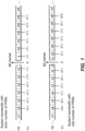
- FIGURE 1 illustrates the center frequency offsets of LTE PRBs for even and odd system bandwidths.
- the DC carrier is placed in between of two PRBs (even number of PRBs) or in the middle of the middle PRB (odd number cases).
- guard-band operation though the granularity does not need to be 1 PRBs, in order to maintain orthogonality to the legacy LTE system and limited the offset to ⁇ 2.5 kHz or ⁇ 7.5 kHz from 100 kHz raster grid, only several positions in the LTE guard-band can be used for the NB-IoT downlink carriers. 7 In the evaluations in [R1-160080] and [R1-160021], 8 ⁇ 2.5 kHz and ⁇ 7.5 kHz offset from the 100 kHz grid can be accommodated by the cell search process.
- R1-160082 NB-IoT Channel Raster, source Ericsson, 3GPP TSG-RAN1 NB-IOT Ad Hoc 18th - 20th Jan 2016, Budapest, Hungary ; and R1-160022, Channel raster design, source Huawei, HiSilicon, 3GPP TSG-RAN1 NB-IOT Ad Hoc 18th - 20th Jan 2016, Budapest, Hungary 7 R1-160082, NB-IoT Channel Raster, source Ericsson, 3GPP TSG-RAN1 NB-IOT Ad Hoc 18th - 20th Jan 2016, Budapest, Hungary 8 R1-160080, NB-IoT -Synchronization Channel Evaluations, source Ericsson, 3GPP TSG-RAN1 NB-IOT Ad Hoc 18th - 20th Jan 2016, Budapest, Hungary ; and R1-160021, Synchronization signal evaluation, source Huawei, HiSilicon, 3GPP TSG-RAN1 NB-IOT Ad Hoc 18th - 20th Jan 2016, Budapest,
- guard-band operation As shown in [R1-160082], 9 for an LTE system with 10 or 20 MHz system bandwidth, it is possible to find NB-IoT downlink carrier frequency that is 2.5 kHz off the 100 kHz frequency raster. For other LTE system bandwidth, the offset to the 100 kHz raster is 52.5 kHz. Therefore, in order to get within the same ⁇ 7.5 kHz to the 100 kHz grid, 3 guard subcarriers are needed.
- One guard carrier is 15 kHz width and placed in the same FFT grid at the legacy LTE system that gives orthogonality to the legacy LTE PRB.
- a 6 dB power boosting is preferred for the downlink of the in-band and guard-band deployment. 10
- the power boosting is with respect to the legacy data channel. But due to spectrum requirement, this 6 dB power boosting cannot be applied at arbitrary places in the guard band.
- NB-IoT devices without good coverage can still be reached when the transmit power is not high enough. But this is at an expense of the system capacity. This can be very problematic when the network traffic is heavier than usual, e.g., for the case of software and firmware update. Therefore, multi-PRB operations are proposed in Rel-13 NB-IoT to help to alleviate the problem.
- an NB-IoT listens to the anchor carrier for system information, but its data transmission in connected mode can be done on other UL/DL carriers referred sometimes to secondary PRBs or non-anchor carriers.
- the non-anchor carrier position(s) can be sent to the NB-IoT devices explicitly, e.g., by RRC configuration or via system information, as described in U.S. Patent Application 62/292,053 (Attorney Docket No. P49310 US1). Accordingly, the positions of the non-anchor carrier in the downlink are not constrained to near the 100 kHz grid. In this way, NB-IoT devices in good coverage can be moved to non-anchor carriers with lower power, and NB-IoT devices in bad coverage can be served by carriers/PRBs with higher power boosting.
- the deployment is more flexible, as it is not necessary to put the UL carrier in a position that is near the 100 kHz grid. That is the NB-IoT device can get the downlink and uplink carrier duplex distance via system information (can be configured on an individual UE basis as described in [R1-161548] 12 ), if the default duplex distance is not applied. Therefore, the placement of the uplink NB-IoT anchor carrier has more flexibility. For the downlink operation, only 15 kHz subcarrier spacing is used for the NB-IoT system.
- paging and NPRACH can only be carried on the anchor carrier, even when multiple carriers are configured for NB-IoT.
- the load of paging and NPRACH transmissions also increase. Therefore, in [RP-161324] 14 it is proposed to study sending paging and random access Msg1/Msg3 on non-anchor NB-IoT carriers. At this moment, a PDCCH order cannot point out an UL carrier (only the NPRACH resource and the start subcarrier) where the UE in connected mode performs its random access transmission.
- a random access carrier e.g., UL PRACH carrier
- a random access transmission on an UL carrier is part of a random access procedure (the random access procedure includes both UL and DL transmissions).
- the random access procedures is initiated by UEs in connected mode when receiving a PDCCH order and by UEs in idle mode when being paged (i.e. receiving a paging message addressed to its UE identity).
- the random access carrier information can be carried in downlink control information (DCI) (e.g., DCI transmitted on NPDDCH) or in paging messages (e.g., paging messages transmitted on NPDSCH).
- DCI downlink control information
- paging messages e.g., paging messages transmitted on NPDSCH
- a method for use in a network node comprises broadcasting system information.
- the system information indicates a set of configured random access carriers.
- the method further comprises selecting, from the set of configured random access carriers, a random access carrier to be used by a wireless device when performing random access transmissions, and indicating the selected random access carrier to the wireless device.
- a network node comprises one or more interfaces and one or more processors.
- the one or more interfaces are operable to broadcast system information.
- the system information indicates a set of configured random access carriers.
- the one or more processors are operable to select, from the set of configured random access carriers, a random access carrier to be used by a wireless device when performing random access transmissions, and to indicate the selected random access carrier to the wireless device.
- a computer program product comprises a non-transitory computer readable storage medium having computer readable program code embodied therein.
- the computer readable program code comprises computer readable program code to broadcast system information.
- the system information indicates a set of configured random access carriers.
- the computer readable program code comprises computer readable program code to select, from the set of configured random access carriers, a random access carrier to be used by a wireless device when performing random access transmissions, and computer readable program code to indicate the selected random access carrier to the wireless device.
- a method for use in a wireless device comprises receiving system information being broadcast by a network node.
- the system information indicates a set of configured random access carriers supported by the network node.
- the method comprises determining whether the network node has indicated a selected random access carrier from the set of configured random access carriers.
- the method comprises performing random access transmissions using the selected random access carrier indicated by the network node.
- the method comprises performing random access transmissions using a random access carrier that the wireless device selects from the set of configured random access carriers.
- wireless device comprises one or more interfaces and one or more processors.
- the one or more interfaces are operable to receive system information being broadcast by a network node.
- the system information indicates a set of configured random access carriers supported by the network node.
- the one or more processors are operable to determine whether the network node has indicated a selected random access carrier from the set of configured random access carriers.
- the one or more processors are operable to perform a random access transmission using the selected random access carrier indicated by the network node.
- the one or more processors are operable to perform a random access transmission using a random access carrier that the wireless device selects from the set of configured random access carriers.
- a computer program product comprises a non-transitory computer readable storage medium having computer readable program code embodied therein.
- the computer readable program code comprises computer readable program code to receive system information being broadcast by a network node.
- the system information indicates a set of configured random access carriers supported by the network node.
- the computer readable program code comprises computer readable program code to determine whether the network node has indicated a selected random access carrier from the set of configured random access carriers.
- the computer readable program code performs a random access transmission using the selected random access carrier indicated by the network node.
- the computer readable program code performs a random access transmission using a random access carrier that the wireless device selects from the set of configured random access carriers.
- an index can be used to indicate the selected random access carrier. Any suitable index may be used. As one example, an index value of 1 could indicate the selection of the first random access carrier listed in the system information, an index value of 2 could indicate the selection of the second random access carrier listed in the system information, and so on. Other embodiments may use other indexes, for example index 0 could indicate the first random access carrier in the list and index 1 the second random access carrier in the list.
- the selected random access carrier can be indicated by communicating downlink control information (DCI) from the network node that explicitly indicates the selected random access carrier to the wireless device.
- DCI downlink control information
- the DCI may use the index discussed above to explicitly indicate the selected random access carrier.
- Certain embodiments carry the DCI on a control channel.
- the control channel can be a physical downlink control channel (PDCCH), such as a Narrowband PDCCH (NPDCCH).
- PDCH physical downlink control channel
- NPDCCH Narrowband PDCCH
- the DCI can be sent in a control channel order, such as a PDCCH order or an NPDCCH order that is sent to the wireless device in connected mode and that orders the wireless device to perform a random access transmission.
- a control channel order such as a PDCCH order or an NPDCCH order that is sent to the wireless device in connected mode and that orders the wireless device to perform a random access transmission.
- the DCI can be sent in a scheduling message that schedules a paging message.
- the scheduling message indicates the selected random access carrier to be used by the wireless device when performing the random access transmission that is initiated in response to the wireless device receiving the paging message.
- the scheduling message can be sent to the wireless device in idle mode.
- a paging message from the network node may be used to indicate the selected random access carrier to be used by the wireless device when performing the random access transmission that is initiated in response to the wireless device receiving the paging message.
- the paging message is communicated via a Narrowband Physical Downlink Shared Channel PDSCH (NPDSCH) or other PDSCH.
- NPDSCH Narrowband Physical Downlink Shared Channel
- the system information broadcast by the network node provides information about downlink (DL) carriers and uplink (UL) carriers.
- the UL carriers belong to the set of configured random access carriers.
- the information about the carriers indicates an association between one of the DL carriers and a default UL carrier.
- the association implicitly indicates the selected random access carrier to the wireless device. For example, a message communicated on a particular DL carrier indicates that the selected random access carrier corresponds to the default UL carrier that the system information associates with the particular DL carrier that communicated the message. Any suitable message may be used to implicitly indicate the selected random access carrier, such as a control channel order, a scheduling message, or a paging message sent on a DL carrier having an associated default UL carrier.
- a method for use in a network node comprises selecting a DL carrier for sending a paging message to a wireless device.
- the selected DL carrier is selected from a set of configured DL carriers.
- the method comprises sending downlink control information (DCI) to the wireless device via a physical downlink control channel (PDCCH).
- the DCI schedules the paging message and indicates the selected DL carrier for the paging message.
- the method further comprises sending the paging message on the selected DL carrier, the paging message carried on a Physical Downlink Shared Channel (PDSCH).
- DCI downlink control information
- PDSCH Physical Downlink Shared Channel
- a network node comprises one or more processors and one or more interfaces.
- the one or more processors are operable to select a DL carrier for sending a paging message to a wireless device.
- the selected DL carrier is selected from a set of configured DL carriers.
- the one or more interfaces are operable to send downlink control information (DCI) to the wireless device via a physical downlink control channel (PDCCH).
- DCI downlink control information
- the DCI schedules the paging message and indicates the selected DL carrier for the paging message.
- the one or more interfaces are further operable to send the paging message on the selected DL carrier, the paging message carried on a Physical Downlink Shared Channel (PDSCH).
- PDSCH Physical Downlink Shared Channel
- a computer program product comprises a non-transitory computer readable storage medium having computer readable program code embodied therein.
- the computer readable program code comprises computer readable program code to select a DL carrier for sending a paging message to a wireless device.
- the selected DL carrier is selected from a set of configured DL carriers.
- the computer readable program code comprises computer readable program code to send downlink control information (DCI) to the wireless device via a physical downlink control channel (PDCCH).
- the DCI schedules the paging message and indicates the selected DL carrier for the paging message.
- the computer readable program code further comprises computer readable program code to send the paging message on the selected DL carrier, the paging message carried on a Physical Downlink Shared Channel (PDSCH).
- PDSCH Physical Downlink Shared Channel
- a method for use in a wireless device comprises receiving downlink control information (DCI) from a network node via a physical downlink control channel (PDCCH).
- the DCI schedules a paging message.
- the method comprises determining, from the set of configured DL carriers, a selected DL carrier for receiving the paging message.
- the selected DL carrier is determined based on an indication in the DCI received from the network node.
- the method further comprises receiving the paging message on the selected DL carrier.
- the paging message is carried on a Physical Downlink Shared Channel (PDSCH).
- PDSCH Physical Downlink Shared Channel
- a wireless device comprises one or more interfaces and one or more processors.
- the one or more interfaces are operable to receive downlink control information (DCI) from a network node via a physical downlink control channel (PDCCH).
- the DCI schedules a paging message.
- the one or more processors are operable to determine, from the set of configured DL carriers, a selected DL carrier for receiving the paging message.
- the selected DL carrier is determined based on an indication in the DCI received from the network node.
- the one or more interfaces are further operable to receive the paging message on the selected DL carrier.
- the paging message is carried on a Physical Downlink Shared Channel (PDSCH).
- PDSCH Physical Downlink Shared Channel
- a computer program product comprises a non-transitory computer readable storage medium having computer readable program code embodied therein.
- the computer readable program code comprises computer readable program code to receive downlink control information (DCI) from a network node via a physical downlink control channel (PDCCH).
- the DCI schedules a paging message.
- the computer readable program code comprises computer readable program code to determine, from the set of configured DL carriers, a selected DL carrier for receiving the paging message.
- the selected DL carrier is determined based on an indication in the DCI received from the network node.
- the computer readable program code further comprises computer readable program code to receive the paging message on the selected DL carrier.
- the paging message is carried on a Physical Downlink Shared Channel (PDSCH).
- PDSCH Physical Downlink Shared Channel
- Certain embodiments of the present disclosure may provide one or more technical advantages. Certain embodiments may allow the network to control on what UL carrier a UE accesses the system as part of being paged. Certain embodiments may allow the network to control on what DL carrier the paging message is transmitted. Certain embodiments may potentially allow for improved load distribution, power consumption, power efficiency, and/or energy savings. Certain embodiments may have all, some, or none of these advantages. Other advantages will be apparent to persons of ordinary skill in the art.
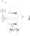
- FIGURE 2 illustrates an example of a wireless network 100 that may be used for wireless communications.
- Wireless network 100 includes wireless devices 110a-110b (e.g., user equipment, UEs) and a plurality of network nodes, such as radio access nodes 120a-120b (e.g., eNBs, gNBs, etc.) connected to one or more core network nodes 130 via an interconnecting network 125.
- Wireless devices 110 within coverage area 115 may each be capable of communicating directly with radio access nodes 120 over a wireless interface.
- wireless devices may also be capable of communicating with each other via device-to-device (D2D) communication.
- D2D device-to-device
- wireless device 110a may communicate with radio access node 120a over a wireless interface. That is, wireless device 110a may transmit wireless signals and/or receive wireless signals from radio access node 120a.
- the wireless signals may contain voice traffic, data traffic, control signals, and/or any other suitable information.
- an area of wireless signal coverage associated with a radio access node 120 may be referred to as a cell.
- wireless device 110 may be interchangeably referred to by the non-limiting term user equipment (UE).
- UE user equipment
- Wireless device 110 can be any type of wireless device capable of communicating with a network node or another UE over radio signals.
- the UE may also be radio communication device, target device, device to device (D2D) UE, machine type UE or UE capable of MTC or machine-to-machine communication (M2M), a sensor equipped with UE, iPAD, Tablet, mobile terminals, smart phone, laptop embedded equipped (LEE), laptop mounted equipment (LME), USB dongles, Customer Premises Equipment (CPE), etc.
- D2D device to device
- M2M machine-to-machine communication
- iPAD machine-to-machine communication
- Tablet mobile terminals
- smart phone laptop embedded equipped (LEE), laptop mounted equipment (LME), USB dongles, Customer Premises Equipment (CPE), etc.
- CPE Customer Premises Equipment
- network node can be any kind of network node which may comprise of a radio network node such as radio access node 120 (which can include a base station, radio base station, base transceiver station, base station controller, network controller, gNB, NR BS, evolved Node B (eNB), Node B, Multi-cell/multicast Coordination Entity (MCE), relay node, access point, radio access point, Remote Radio Unit (RRU), Remote Radio Head (RRH), a multi-standard BS (also known as MSR BS), etc.), a core network node (e.g., mobile management entity, MME, self-organizing network node, SON node, a coordinating node, positioning node, minimization of drive test node, MDT node, etc.), or even an external node (e.g., 3rd party node, a node external to the current network), etc.
- a radio network node such as radio access node 120 (which can include a base station, radio base station, base trans
- the network node may also comprise test equipment.
- the term "radio node” may be used to denote a UE (e.g., wireless device 110) or a radio network node (e.g., radio access node 120).
- a radio network node e.g., radio access node 120
- An example embodiment of radio access node 120 is described in more detail below with respect to FIGURE 10 .
- radio access nodes 120 may interface with a radio network controller.
- the radio network controller may control radio access nodes 120 and may provide certain radio resource management functions, mobility management functions, and/or other suitable functions.
- the functions of the radio network controller may be included in radio access node 120.
- the radio network controller may interface with a core network node 130.
- the radio network controller may interface with the core network node 130 via an interconnecting network 125.
- the interconnecting network 125 may refer to any interconnecting system capable of transmitting audio, video, signals, data, messages, or any combination of the preceding.
- the interconnecting network 125 may include all or a portion of a public switched telephone network (PSTN), a public or private data network, a local area network (LAN), a metropolitan area network (MAN), a wide area network (WAN), a local, regional, or global communication or computer network such as the Internet, a wireline or wireless network, an enterprise intranet, or any other suitable communication link, including combinations thereof.
- PSTN public switched telephone network
- LAN local area network
- MAN metropolitan area network
- WAN wide area network
- Internet a local, regional, or global communication or computer network
- wireline or wireless network an enterprise intranet, or any other suitable communication link, including combinations thereof.
- the core network node 130 may manage the establishment of communication sessions and various other functionalities for wireless devices 110.
- Examples of core network node 130 may include mobile switching center (MSC), MME, serving gateway (SGW), packet data network gateway (PGW), operation and maintenance (O&M), operations support system (OSS), SON, positioning node (e.g., Enhanced Serving Mobile Location Center, E-SMLC), MDT node, etc.
- Wireless devices 110 may exchange certain signals with the core network node using the non-access stratum layer. In non-access stratum signaling, signals between wireless devices 110 and the core network node 130 may be transparently passed through the radio access network.
- radio access nodes 120 may interface with one or more network nodes over an internode interface. For example, radio access nodes 120a and 120b may interface over an X2 interface.
- FIGURE 2 illustrates a particular arrangement of network 100
- network 100 may include any suitable number of wireless devices 110 and radio access nodes 120, as well as any additional elements suitable to support communication between wireless devices or between a wireless device and another communication device (such as a landline telephone).
- the embodiments may be implemented in any appropriate type of telecommunication system supporting any suitable communication standards and using any suitable components, and are applicable to any radio access technology (RAT) or multi-RAT systems in which the wireless device receives and/or transmits signals (e.g., data).
- RAT radio access technology
- multi-RAT systems in which the wireless device receives and/or transmits signals (e.g., data).
- NR and/or LTE the embodiments are applicable to any RAT, such as Universal Mobile Telecommunications System Terrestrial Radio Access Network (UTRA), enhanced UTRA (E-UTRA), narrow band internet of things (NB-IoT), WiFi, Bluetooth, next generation RAT (NR, NX), 4G, 5G, LTE FDD/TDD, Wideband Code Division Multiple Access (WCDMA), High Speed Packet Access (HSPA), Global System for Mobile Communication (GSM), GSM Edge Radio Access Network (GERAN), WLAN, CDMA2000, etc.
- UTRA Universal Mobile Telecommunications System Terrestrial Radio Access Network
- E-UTRA enhanced UTRA
- NB-IoT narrow band internet of things
- WiFi Bluetooth
- next generation RAT NR, NX
- 4G 5G
- LTE FDD/TDD Wideband Code Division Multiple Access
- WCDMA Wideband Code Division Multiple Access
- HSPA High Speed Packet Access
- GSM Global System for Mobile Communication
- GERAN GSM Edge Radio Access Network
- WLAN CDMA2000
- FIGURES 3-8 are signal flow diagrams illustrating examples of signals sent between a wireless device 110 and a network node, such as radio access node 120, in accordance with certain embodiments.
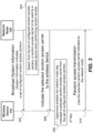
- FIGURES 3 illustrates a general embodiment in which the network node indicates a random access carrier to be used by wireless device 110.
- FIGURES 4-6 illustrate examples implementations of the method illustrated in FIGURE 3 , in accordance with certain embodiments.
- FIGURE 7 illustrates an example in which wireless device 110 selects the random access carrier in response to determining that the network node has not indicated the random access carrier.
- FIGURE 8 illustrates an example in which the network node indicates a DL carrier to be used for a paging message.
- the network node broadcasts system information to wireless devices within the coverage area of the network node.
- the system information indicates a set of configured random access carriers.
- the random access carriers support PRACHs.
- a PRACH may refer to a physical random access channel used by any suitable radio access technology, such as the PRACH used in LTE, the NPRACH used in NB-IoT, or future evolutions of the PRACH.
- the network node selects a random access carrier to be used by one of the wireless devices 110 when that wireless device 110 performs a random access transmission.
- the selected random access carrier is selected from the set of configured random access carriers broadcast by the network node in step 302.
- the network node determines the random access carrier to select based on a load balancing procedure that distributes the load in order to reduce the likelihood of any one of the random access carriers becoming too heavily loaded compared to the other random access carriers.
- the network node indicates the selected random access carrier to wireless device 110.
- the indication may be explicit or implicit.
- the network node uses a control channel message, such as a control channel order or a scheduling message, to indicate the selected random access carrier.
- the control channel message is carried on a PDCCH.
- a PDCCH may refer to a physical downlink control channel used by any suitable radio access technology, such as the PDCCH used in LTE, the NPDCCH used in NB-IoT, or future evolutions of the PDCCH.
- control channel message explicitly indicates the selected random access carrier to wireless device 110.
- a control channel order may include downlink control information (DCI) that explicitly indicates the selected random access carrier to wireless device 110, as shown in FIGURE 4A .
- DCI downlink control information
- a control channel message for scheduling a paging message may include DCI that explicitly indicates the selected random access carrier to be used by the wireless device when performing the random access transmission as part of a paging response, e.g., as shown in FIGURE 4B .
- the control channel message may implicitly indicate the selected random access carrier, an example of which is further discussed below with respect to FIGURE 6 .
- the network node can indicate the selected random access carrier to wireless device 110 by communicating a paging message to wireless device 110.
- the paging message indicates the selected random access carrier to be used by wireless device 110 when performing the random access transmission that is initiated in response to the wireless device receiving the paging message, e.g., as shown in FIGURE 5 .
- the paging message is carried on a PDSCH.
- the PDSCH may refer to a Physical Downlink Shared Channel used by any suitable radio access technology, such as the PDSCH used in LTE, the NPDSCH used in NB-IoT, or future evolutions of the PDSCH.
- wireless device 110 determines whether the network node has indicated a selected random access carrier to be used by wireless device 110. For example, in response to receiving any of the indications discussed above with respect to step 306, wireless device determines that the network node has indicated the selected random access carrier.
- wireless device 110 performs a random access transmission using the selected random access carrier indicated by the network node.
- wireless device 110 if wireless device 110 is initiating an access attempt in response to a control channel order, wireless device 110 transmits the random access message via the random access carrier indicated by the network node in the control channel (see e.g., FIGURE 4A ).
- wireless device 110 if wireless device 110 is responding to a paging message, wireless device 110 initiates the random access transmissions via the random access carrier selected by the network node (see e.g., FIGURES 4B-5 ).
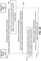
- FIGURES 4A-4B illustrate examples in which the network node indicates a random access carrier to be used by wireless device 110.
- the network node sends downlink control information (DCI) to wireless device 110 in order to explicitly indicate the selected random access carrier.
- DCI downlink control information
- the network node broadcasts system information that indicates a set of configured random access carriers.
- the network node selects a random access carrier to be used by a wireless device 110.
- the selected random access carrier is selected from the set of configured random access carriers broadcast in step 402A.
- the network node sends wireless device 110 a message, such as a control channel message sent via a PDCCH.
- the message sent in step 406A may be a control channel order (e.g., PDCCH order) sent to a connected wireless device 110 and ordering the wireless device 110 to perform a random access procedure.
- the control channel order includes DCI explicitly indicating the selected random access carrier that wireless device 110 should use for the random access transmissions.
- wireless device 110 determines whether the network node has indicated a selected random access carrier. For example, wireless device 110 determines that the network node has indicated the selected random access carrier based on wireless device 110 having received the indication in step 406A.
- wireless device 110 performs the random access transmissions using the selected random access carrier that the network node indicated in step 406A.
- the network node broadcasts system information that indicates a set of configured random access carriers.
- the network node selects a random access carrier to be used by a wireless device 110.
- the selected random access carrier is selected from the set of configured random access carriers broadcast in step 402B.
- the network node sends wireless device 110 a message, such as a control channel message sent via a PDCCH.
- the message sent in step 406B may be a scheduling message sent to an idle wireless device 110 to schedule a paging message.
- the scheduling message includes DCI that explicitly indicates the selected random access carrier that wireless device 110 should use when initiating the random access transmissions in response to receiving the paging message.
- the network node sends the paging message, e.g., via a PDSCH.
- wireless device 110 determines whether the network node has indicated a selected random access carrier for initiating a random access transmission in response to receiving a paging message. For example, wireless device 110 determines that the network node has indicated the selected random access carrier based on wireless device 110 having received the indication in step 406B.
- wireless device 110 initiates the random access transmission using the selected random access carrier that the network node indicated in step 406B.
- FIGURE 5 illustrates another example in which the network node indicates a random access carrier to be used by wireless device 110.
- the network node broadcasts system information that indicates a set of configured random access carriers.
- the network node selects a random access carrier to be used by a wireless device 110.
- the selected random access carrier is selected from the set of configured random access carriers broadcast in step 502.
- the network node sends a paging message.
- the paging message may be sent via a PDSCH.
- the paging message indicates the selected random access carrier that wireless device 110 should use when responding to the paging message.
- wireless device 110 determines whether the network node has indicated a selected random access carrier for performing the random access transmission that is initiated in response to the wireless device receiving the paging message. For example, wireless device 110 determines that the network node has indicated the selected random access carrier based on wireless device 110 having received the indication in step 506. At step 510, wireless device 110 uses the selected random access carrier that the network node indicated in step 506 when performing the random access transmission that is initiated in response to the wireless device receiving the paging message.
- FIGURE 6 illustrates an example in which the network node implicitly indicates a random access carrier to be used by wireless device 110.
- the network node broadcasts system information that indicates a set of downlink carriers (e.g., anchor carrier and non-anchor carriers) and a set of uplink carriers (e.g., anchor carrier and non-anchor carriers).
- the downlink carriers may be used for paging wireless devices and/or other downlink procedures.
- the uplink carriers may be used for random access transmissions and/or other uplink procedures.
- the system information broadcast in step 602 includes information about the association between a DL carrier and a respective default UL carrier.
- the network node selects a UL carrier to be used by the wireless device 110 when performing an uplink procedure, such as a random access attempt.
- the UL carrier is selected from the set of UL carriers indicated in the system information broadcast by the network node in step 602.
- the network node indicates the selected UL carrier to wireless device 110 by transmitting a message on a DL carrier.
- the network node implicitly indicates the selected UL carrier by communicating a message (such as a control channel order, scheduling message, or paging message) to wireless device 110 on the DL carrier for which the associated default UL carrier corresponds to the UL carrier selected in step 604.
- wireless device 110 determines whether the network node has indicated a selected UL carrier. For example, wireless device 110 determines that the network node has indicated a selected UL carrier based on wireless device 110 having received a message in step 606 via a DL carrier that the system information received in step 602 associates with a default UL carrier.
- wireless device performs an uplink procedure, such as transmitting a random access transmission, using the default UL carrier (i.e., the UL carrier associated with the DL carrier that communicated the message in step 606).
- the default UL carrier i.e., the UL carrier associated with the DL carrier that communicated the message in step 606.
- the network node may simply select the DL carrier.
- the subsequent steps would be similar (the network node sends message 606 via the selected DL carrier, and in step 608 wireless device 110 determines the associated default UL carrier based on the association received in the system information broadcast by the network node in step 602).
- FIGURE 7 illustrates an example in which wireless device 110 selects the random access carrier in response to determining that the network node has not indicated the random access carrier.
- wireless device 110 receives system information being broadcast by a the network node. The system information indicates a set of configured random access carriers supported by the network node.
- wireless device 110 determines whether the network node has indicated a selected random access carrier from the set of configured random access carriers.
- wireless device 110 performs the random access transmission using a random access carrier that wireless device 110 selects itself.
- Wireless device 110 selects the random access carrier from the set of configured random access carriers identified in the system information that the network node broadcast in step 702.
- FIGURE 8 illustrates an example in which the network node indicates a DL carrier to be used for a paging message.
- the network node selects a DL carrier for sending a paging message to a wireless device.
- the selected DL carrier is selected from a set of configured DL carriers.
- the network node selects the DL carrier based on a load balancing procedure that distributes the load in order to reduce the likelihood of any one of the DL carriers becoming too heavily loaded compared to the other DL carriers.
- the network node sends DCI to wireless device 110.
- the DCI may be sent via a PDCCH.
- the DCI schedules the paging message and indicates the selected DL carrier for the paging message.
- wireless device 110 determines to monitor the selected DL carrier for the paging message based on the indication received in step 804.
- the network node sends the paging message to wireless device 110 on the selected DL carrier (the DL carrier indicated in step 804).
- the paging message may be carried on a PDSCH.
- embodiments of the present disclosure may be used with any suitable radio access technology.
- Certain embodiments of the present disclosure propose methods for the network to better utilize the UL NPRACH resources when NPRACH resources are configured on non-anchor carriers.
- Currently i.e. in the rel-13 version of the NB-IoT specifications
- when an NB-IoT UE is paged there is no way for it to determine which UL carrier to use to send its NPRACH. Therefore, if there is no good mechanism to distribute the NPRACH load, some of the UL carriers may be overloaded. Therefore, the present disclosure proposes several solutions for the network to better distribute the UL PRACH load.
- Patent Application 62/374,305 (Attorney Docket P50886 US1) provides a few variants of load distribution based on UE selection by using rules and parameters broadcasted on system information. Disclosed herein is more direct dedicated signaling from the NW to individual UEs.
- the general idea is when an NB-IoT UE is sent a message on the NPDCCH being a "paging scheduling" message (DCI message scrambled by P-RNTI), a paging message (the paging message on the NPDSCH being scheduled by previous said P-RNTI scrambled DCI on NPDCCH), or a NPDCCH order (DCI message scrambled by C-RNTI), an indication can be provided which UL carrier that the UE shall use to send it's NPRACH Msg1.
- a "paging scheduling" message DCI message scrambled by P-RNTI
- a paging message the paging message on the NPDSCH being scheduled by previous said P-RNTI scrambled DCI on NPDCCH
- a NPDCCH order DCI message scrambled by C-RNTI
- a PDCCH order indicates the NPRACH carrier.
- a new DCI format on NPDCCH i.e., a "PDCCH order” orders the UE to perform a random access transmission on any NPRACH carrier broadcasted on SI. If the PDCCH order explicitly points out an NPRACH carrier, the UE shall use that one (see e.g., FIGURE 3 ), otherwise the idle mode NPRACH carrier selection is performed by the UE (see e.g., FIGURE 7 ). Also, as discussed above with respect to FIGURE 6 , it is also possible to associate a default UL non-anchor carrier with each DL non-anchor carrier. So, when the NPDCCH order is received on one carrier, the NPRACH is sent on the default associated UL carrier.
- a paging DCI indicates the NPRACH carrier.
- a new DCI format on NPDCCH that schedules a paging message also includes indication to what NPRACH carrier the UE should use in the random access transmission that is part of a paging response. An example of this embodiment is discussed above with respect to FIGURE 4 .
- a paging DCI indicates the paging message carrier.
- a new DCI format on NPDCCH that schedules a paging message also includes indication about the DL carrier used for the paging message (on NPDSCH). An example of this embodiment is discussed above with respect to FIGURE 8 .
- a paging message indicates a NPRACH carrier.
- this embodiment includes the NPRACH carrier in the paging message transmitted on NPDSCH. An example of this embodiment is discussed above with respect to FIGURE 5 .
- the DL and UL non-anchor carrier information is broadcast in the SI. Additionally, in certain embodiments, the default DL and UL non-anchor carrier association is broadcast on the SI.
- FIGURE 6 illustrates an example.
- the network node in addition to the UL non-anchor carrier, can also indicate the specific NPRACH resource, if multiple NPRACH resources are configured on a non-anchor carrier.
- a method in a network node comprises indicating to a wireless device an NPRACH carrier to be used by the wireless device when performing random access transmissions.
- a network node comprises memory and one or more processors.
- the network node is operable to indicate to a wireless device an NPRACH carrier to be used by the wireless device when performing random access transmissions.
- a computer program product comprises a non-transitory computer readable storage medium having computer readable program code embodied in the medium.
- the computer readable program code comprises computer readable program code to indicate to a wireless device an NPRACH carrier to be used by the wireless device when performing random access transmissions.
- a method in wireless device comprises receiving from a network node an indication of an NPRACH carrier to be used by the wireless device when performing random access transmissions, and using the indicated NPRACH carrier when performing the random access transmission.
- a wireless device comprises memory and one or more processors.
- the wireless device is operable to receive from a network node an indication of an NPRACH carrier to be used by the wireless device when performing random access transmissions, and to use the indicated NPRACH carrier when performing the random access transmission.
- a computer program product comprises a non-transitory computer readable storage medium having computer readable program code embodied in the medium.
- the computer readable program code comprises computer readable program code to receive from a network node an indication of an NPRACH carrier to be used by a wireless device when performing random access transmissions, and computer readable program code to use the indicated NPRACH carrier when performing the random access transmission.
- FIGURE 9 is a block diagram of an exemplary wireless device 110, in accordance with certain embodiments.
- Wireless device 110 includes one or more transceivers 905, processing circuitry (which may comprise one or more processors 910), and one or more memories 915.
- transceiver 905 facilitates transmitting wireless signals to and receiving wireless signals from radio access node 120 (e.g., via an antenna), processor 910 executes instructions to provide some or all of the functionality described above as being provided by wireless device 110, and memory 915 stores the instructions for execution by processor 910.
- Processor 910 may include any suitable combination of hardware and software implemented in one or more modules to execute instructions and manipulate data to perform some or all of the described functions of wireless device 110, such as the functions of determining whether the network node has indicated a selected random access carrier to be used by wireless device 110 (as described above with respect to FIGURES 3-7 ) or determining whether the network node has indicated a selected DL carrier to be used for a paging message (as described above with respect to FIGURE 8 ).
- processor 910 may include, for example, one or more computers, one or more central processing units (CPUs), one or more microprocessors, one or more applications, one or more application specific integrated circuits (ASICs), one or more field programmable gate arrays (FPGAs) and/or other logic.
- CPUs central processing units
- microprocessors one or more microprocessors
- applications one or more application specific integrated circuits (ASICs)
- ASICs application specific integrated circuits
- FPGAs field programmable gate arrays
- Memory 915 is generally operable to store instructions, such as a computer program, software, an application including one or more of logic, rules, algorithms, code, tables, etc. and/or other instructions capable of being executed by a processor.
- Examples of memory 915 include computer memory (for example, Random Access Memory (RAM) or Read Only Memory (ROM)), mass storage media (for example, a hard disk), removable storage media (for example, a Compact Disk (CD) or a Digital Video Disk (DVD)), and/or or any other volatile or non-volatile, non-transitory computer-readable and/or computer-executable memory devices that store information, data, and/or instructions that may be used by processor 910 of wireless device 110.
- RAM Random Access Memory
- ROM Read Only Memory
- mass storage media for example, a hard disk
- removable storage media for example, a Compact Disk (CD) or a Digital Video Disk (DVD)
- CD Compact Disk
- DVD Digital Video Disk
- wireless device 110 may include additional components beyond those shown in FIGURE 9 that may be responsible for providing certain aspects of the wireless device's functionality, including any of the functionality described above and/or any additional functionality (including any functionality necessary to support the solution described above).
- wireless device 110 may include input devices and circuits, output devices, and one or more synchronization units or circuits, which may be part of processor 910.
- Input devices include mechanisms for entry of data into wireless device 110.
- input devices may include input mechanisms, such as a microphone, input elements, a display, etc.
- Output devices may include mechanisms for outputting data in audio, video and/or hard copy format.
- output devices may include a speaker, a display, etc.
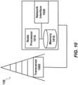
- FIGURE 10 is a block diagram of an exemplary radio access node 120, in accordance with certain embodiments.
- Radio access node 120 may include one or more of transceiver(s) 1005, processing circuitry (which may comprise one or more processors 1010), memory(ies) 1015, and network interface(s) 1020.
- transceiver 1005 facilitates transmitting wireless signals to and receiving wireless signals from wireless device 110 (e.g., via an antenna), processor 1010 executes instructions to provide some or all of the functionality described above as being provided by a network node or radio access node 120, memory 1015 stores the instructions for execution by processor 1010, and network interface 1020 communicates signals to backend network components, such as a gateway, switch, router, Internet, Public Switched Telephone Network (PSTN), core network nodes or radio network controllers, etc.
- PSTN Public Switched Telephone Network
- Processor 1010 may include any suitable combination of hardware and software implemented in one or more modules to execute instructions and manipulate data to perform some or all of the described functions of a network node or radio access node 120, such as indicating a selected random access carrier to be used by wireless device 110 (as described above with respect to FIGURES 3-7 ) or indicating a selected DL carrier to be used for a paging message (as described above with respect to FIGURE 8 ).
- processor 1010 may include, for example, one or more computers, one or more central processing units (CPUs), one or more microprocessors, one or more applications, one or more application specific integrated circuits (ASICs), one or more field programmable gate arrays (FPGAs) and/or other logic.
- Memory 1015 is generally operable to store instructions, such as a computer program, software, an application including one or more of logic, rules, algorithms, code, tables, etc. and/or other instructions capable of being executed by a processor.
- Examples of memory 1015 include computer memory (for example, Random Access Memory (RAM) or Read Only Memory (ROM)), mass storage media (for example, a hard disk), removable storage media (for example, a Compact Disk (CD) or a Digital Video Disk (DVD)), and/or or any other volatile or non-volatile, non-transitory computer-readable and/or computer-executable memory devices that store information.
- RAM Random Access Memory
- ROM Read Only Memory
- mass storage media for example, a hard disk
- removable storage media for example, a Compact Disk (CD) or a Digital Video Disk (DVD)
- CD Compact Disk
- DVD Digital Video Disk
- network interface 1020 is communicatively coupled to processor 1010 and may refer to any suitable device operable to receive input for radio access node 120, send output from radio access node 120, perform suitable processing of the input or output or both, communicate to other devices, or any combination of the preceding.
- Network interface 1020 may include appropriate hardware (e.g., port, modem, network interface card, etc.) and software, including protocol conversion and data processing capabilities, to communicate through a network.
- radio access node 120 may include additional components beyond those shown in FIGURE 10 that may be responsible for providing certain aspects of the radio network node's functionality, including any of the network node functionality described above and/or any additional functionality (including any functionality necessary to support the solutions described above).
- the various different types of network nodes may include components having the same physical hardware but configured (e.g., via programming) to support different radio access technologies, or may represent partly or entirely different physical components.
- Processors, interfaces, and memory similar to those described with respect to FIGURES 9-10 may be included in other network nodes (such as core network node 130).
- Other network nodes may optionally include or not include a wireless interface (such as the transceiver described in FIGURES 9-10 ).
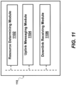
- FIGURE 11 illustrates examples of modules that may be included in wireless device 110.
- wireless device 110 may include a resource determining module 1102, an uplink messaging module 1104, and/or a downlink receiving module 1106.
- Resource determining module 1102 may determine a random access carrier to use for a random access transmission.
- resource determining module 1102 may be configured to perform one or more of steps 308, 410A, 410B, 508, 608, and/ or 704 discussed above with respect to FIGURES 3 , 4A , 4B , 5 , 6 , and 7 , respectively.
- the determination can be based on an indication from a the network node or, if the network node does not indicate which random access carrier to use, wireless device 110 may decide on its own.
- the network node can indicate the random access carrier in any suitable message, such as a message comprising DCI information (such as a control channel order or a message scheduling a paging message), a paging message, and so on.
- Uplink messaging module 1104 sends random access messages using the random access carrier determined by resource determining module 1102.
- uplink messaging module 1104 may be configured to perform one or more of steps 310, 412A, 412B, 510, 610, and/or 706 discussed above with respect to FIGURES 3 , 4A , 4B , 5 , 6 , and 7 , respectively.
- downlink receiving module 1106 may receive signals from the network node, such as signals 302 and/or 306 of FIGURE 3 , signals 402A and/or 406A of FIGURE 4A , signals 402B, 406B, and/or 408B of FIGURE 4B , signals 502 and/or 506 of FIGURE 5 , signals 602 and/or 606 of FIGURE 6 , signal 702 of FIGURE 7 , and/or signals 804 and/or 806 of FIGURE 8 .
- resource determining module 1102 may determine a DL carrier to use to receive a paging message (step 805) based on DCI received by downlink receiving module 1106 in step 804.
- resource determining module 1102, uplink messaging module 1104, and/or downlink receiving module are implemented using one or more processors 910 discussed with respect to FIGURE 9 .
- the modules may be integrated or separated in any manner suitable for performing the described functionality.
- FIGURE 12 illustrates examples of modules that may be included in radio access node 120.
- radio access node 120 may include a resource determining module 1202, a resource indicating module 1204, and/or a uplink receiving module 1206.
- Resource determining module 1202 may determine a random access carrier to be used by respective wireless device(s) 110 or a DL carrier to be used to send paging messages to respective wireless device(s) 110.
- resource determining module 1202 may determine the random access carrier at least in part to balance the utilization of random access carriers in order to avoid a large number of wireless devices 110 all attempting to use the same random access carriers.
- resource determining module 1202 may be configured to perform one or more of steps 304, 404A, 404B, 504, 604, and/ or 802 discussed above with respect to FIGURES 3 , 4A , 4B , 5 , 6 , and 8 , respectively.
- Resource indicating module 1204 indicates the determined carrier to the wireless device(s) 110.
- Resource indicating module 1204 can cause the network node to indicate the carrier in any suitable message, such as a message comprising DCI information (such as a message scheduling a paging message or a control channel order), a paging message, and so on.
- resource indicating module 1204 may be configured to perform one or more of steps 306, 406A, 406B, 506, 606, or 804 discussed above with respect to FIGURES 3 , 4A , 4B , 5 , 6 , and 8 , respectively.
- Uplink receiving module 1206 receives messages from wireless device 110. For example, uplink receiving module 1206 may receive the random access transmissions via the random access carrier selected by resource determining module 1202 and communicated by resource indicating module 1204. Examples of messages that may be received by uplink receiving module include messages of steps 310, 412A, 412B, 510, 610, and/or 706 of FIGURES 3 , 4A , 4B , 5 , 6 , and 7 , respectively.
- resource determining module 1202, resource indicating module 1204, and/or uplink receiving module 1206 are implemented using one or more processors discussed with respect to FIGURE 10 .
- the modules may be integrated or separated in any manner suitable for performing the described functionality.
- any two or more embodiments described in this document may be combined in any way with each other.
- the described embodiments are not limited to the described radio access technologies (e.g., LTE, NB-IoT, NR). That is, the described embodiments can be adapted to other radio access technologies.
Landscapes
- Engineering & Computer Science (AREA)
- Computer Networks & Wireless Communication (AREA)
- Signal Processing (AREA)
- Mobile Radio Communication Systems (AREA)
- Management, Administration, Business Operations System, And Electronic Commerce (AREA)
- Reduction Or Emphasis Of Bandwidth Of Signals (AREA)
- Noise Elimination (AREA)
Applications Claiming Priority (3)
| Application Number | Priority Date | Filing Date | Title |
|---|---|---|---|
| US201662374600P | 2016-08-12 | 2016-08-12 | |
| PCT/IB2017/054906 WO2018029643A1 (en) | 2016-08-12 | 2017-08-11 | New dci formats for non-anchor operations |
| EP17768513.8A EP3498029B1 (de) | 2016-08-12 | 2017-08-11 | Neue dci-formate für nicht-anker-operationen |
Related Parent Applications (2)
| Application Number | Title | Priority Date | Filing Date |
|---|---|---|---|
| EP17768513.8A Division-Into EP3498029B1 (de) | 2016-08-12 | 2017-08-11 | Neue dci-formate für nicht-anker-operationen |
| EP17768513.8A Division EP3498029B1 (de) | 2016-08-12 | 2017-08-11 | Neue dci-formate für nicht-anker-operationen |
Publications (2)
| Publication Number | Publication Date |
|---|---|
| EP4307818A2 true EP4307818A2 (de) | 2024-01-17 |
| EP4307818A3 EP4307818A3 (de) | 2024-03-06 |
Family
ID=59895335
Family Applications (2)
| Application Number | Title | Priority Date | Filing Date |
|---|---|---|---|
| EP17768513.8A Active EP3498029B1 (de) | 2016-08-12 | 2017-08-11 | Neue dci-formate für nicht-anker-operationen |
| EP23213230.8A Withdrawn EP4307818A3 (de) | 2016-08-12 | 2017-08-11 | Neue dci-formate für nicht-anker-operationen |
Family Applications Before (1)
| Application Number | Title | Priority Date | Filing Date |
|---|---|---|---|
| EP17768513.8A Active EP3498029B1 (de) | 2016-08-12 | 2017-08-11 | Neue dci-formate für nicht-anker-operationen |
Country Status (6)
| Country | Link |
|---|---|
| US (2) | US11582792B2 (de) |
| EP (2) | EP3498029B1 (de) |
| AU (3) | AU2017309417A1 (de) |
| IL (1) | IL264781B2 (de) |
| MX (1) | MX2019001710A (de) |
| WO (1) | WO2018029643A1 (de) |
Families Citing this family (7)
| Publication number | Priority date | Publication date | Assignee | Title |
|---|---|---|---|---|
| US11582792B2 (en) | 2016-08-12 | 2023-02-14 | Telefonaktiebolaget Lm Ericsson (Publ) | DCI formats for non-anchor operations |
| EP3665999B1 (de) | 2017-08-09 | 2020-11-04 | Telefonaktiebolaget LM Ericsson (publ) | Netzwerkknoten und verfahren in einem drahtloskommunikationsnetzwerk |
| US11737040B2 (en) | 2017-08-09 | 2023-08-22 | Telefonaktiebolaget Lm Ericsson (Publ) | Systems and methods for obtaining timing advances |
| EP3735057B1 (de) * | 2018-01-31 | 2023-01-11 | Guangdong Oppo Mobile Telecommunications Corp., Ltd. | Funkrufverfahren, endgerät und netzwerkvorrichtung |
| CN111771407B (zh) * | 2018-02-12 | 2023-11-17 | 华为技术有限公司 | 一种通信方法、通信设备及计算机程序存储介质 |
| US10932149B2 (en) * | 2018-04-05 | 2021-02-23 | Qualcomm Incorporated | Using narrowband reference signal (NRS) tones in a non-anchor carrier to determine quality of the non-anchor carrier |
| WO2020020429A1 (en) * | 2018-07-23 | 2020-01-30 | Shenzhen GOODIX Technology Co., Ltd. | FLEXIBLE NB-IoT MULTI-CARRIER OPERATION ACROSS RADIO FREQUENCY BANDS |
Family Cites Families (16)
| Publication number | Priority date | Publication date | Assignee | Title |
|---|---|---|---|---|
| JP5097142B2 (ja) * | 2009-02-04 | 2012-12-12 | 株式会社エヌ・ティ・ティ・ドコモ | 移動通信方法及び無線基地局 |
| KR101855425B1 (ko) * | 2009-03-12 | 2018-05-08 | 인터디지탈 패튼 홀딩스, 인크 | 업링크 일차 반송파를 선택 및 재선택하는 방법 및 장치 |
| CN104968054A (zh) | 2009-04-23 | 2015-10-07 | 交互数字专利控股公司 | 在eNB中实施的方法及eNB |
| CN101877621A (zh) * | 2009-04-30 | 2010-11-03 | 三星电子株式会社 | 用于lte-a系统中下行控制信道pdcch的发送方法及发送装置 |
| CA2775305C (en) * | 2009-09-25 | 2017-07-11 | Research In Motion Limited | System and method for multi-carrier network operation |
| KR101763596B1 (ko) * | 2010-01-06 | 2017-08-01 | 엘지전자 주식회사 | 복수의 컴포넌트 캐리어를 지원하는 무선통신 시스템에서 크로스-캐리어 스케쥴링을 통한 데이터 전송 방법 및 장치 |
| CN107769900B (zh) * | 2011-02-07 | 2020-12-29 | 交互数字专利控股公司 | 一种载波聚合方法 |
| CN109327822B (zh) | 2012-10-05 | 2022-10-25 | 交互数字专利控股公司 | 增强机器类型通信(mtc)设备覆盖的方法和装置 |
| JP6937685B2 (ja) * | 2014-08-15 | 2021-09-22 | インターデイジタル パテント ホールディングス インコーポレイテッド | Lteシステムにおける低減能力wtruのためのランダムアクセスおよびページングの手順のサポート |
| WO2017050498A1 (en) * | 2015-09-25 | 2017-03-30 | Sony Corporation | Methods, apparatuses and system for transmission of a connection request message in a wireless communications system |
| US20170238284A1 (en) * | 2016-02-05 | 2017-08-17 | Mediatek Inc. | Multi-Carrier Operation for Narrowband Internet of Things |
| CN107046707B (zh) * | 2016-02-06 | 2021-11-16 | 中兴通讯股份有限公司 | 频点选择方法及装置 |
| US10932297B2 (en) * | 2016-04-05 | 2021-02-23 | Sony Corporation | Wireless telecommunications apparatus and methods |
| US10681684B2 (en) * | 2016-07-18 | 2020-06-09 | Qualcomm Incorporated | Multi-PRB paging/random access for NB-IoT |
| US20190239051A1 (en) * | 2016-08-10 | 2019-08-01 | Lg Electronics Inc. | Method for receiving paging signal in nb-iot and method for performing random access procedure in nb-iot |
| US11582792B2 (en) | 2016-08-12 | 2023-02-14 | Telefonaktiebolaget Lm Ericsson (Publ) | DCI formats for non-anchor operations |
-
2017
- 2017-08-11 US US16/325,121 patent/US11582792B2/en active Active
- 2017-08-11 EP EP17768513.8A patent/EP3498029B1/de active Active
- 2017-08-11 AU AU2017309417A patent/AU2017309417A1/en not_active Abandoned
- 2017-08-11 WO PCT/IB2017/054906 patent/WO2018029643A1/en not_active Ceased
- 2017-08-11 MX MX2019001710A patent/MX2019001710A/es unknown
- 2017-08-11 EP EP23213230.8A patent/EP4307818A3/de not_active Withdrawn
- 2017-08-11 IL IL264781A patent/IL264781B2/en unknown
-
2020
- 2020-10-23 AU AU2020257156A patent/AU2020257156A1/en not_active Abandoned
-
2022
- 2022-08-10 AU AU2022215215A patent/AU2022215215B2/en not_active Expired - Fee Related
-
2023
- 2023-02-13 US US18/108,918 patent/US20230199829A1/en not_active Abandoned
Non-Patent Citations (9)
| Title |
|---|
| ERICSSON: "NB-IoT Channel Raster", 3GPP TSG-RAN1 NB-IOT AD HOC |
| ERICSSON: "NB-IoT Channel Raster", 3GPP TSG-RAN1 NB-IOT AD HOC, 18 January 2016 (2016-01-18) |
| ERICSSON: "NB-IoT -Synchronization Channel Evaluations", 3GPP TSG-RANI NB-IOT AD HOC, 18 January 2016 (2016-01-18) |
| ERICSSON: "RANI agreements for Rel-13 NB-IoT", 3GPP TSG-RAN WG1 MEETING #84, 15 February 2016 (2016-02-15) |
| ERICSSON: "RANI agreements for Rel-13 NB-IoT", 3GPP TSG-RAN WG1 MEETING #84, ST. JULIAN'S, MALTA, 15 February 2016 (2016-02-15) |
| HUAWEIHISILICON: "Channel raster design", 3GPP TSG-RAN1 NB-IOT AD HOC, 18 January 2016 (2016-01-18) |
| HUAWEIHISILICON: "Synchronization signal evaluation", 3GPP TSG-RANI NB-IOT AD HOC, 18 January 2016 (2016-01-18) |
| VODAFONEHUAWEIHISILICONERICSSONQUALCOMM: "New work item proposal: Enhancements of NB-IoT", 3GPP TSG RAN MEETING #72, BUSAN, KOREA |
| VODAFONEHUAWEIHISILICONERICSSONQUALCOMM: "New work item proposal: Enhancements of NB-IoT", 3GPP TSG RAN MEETING #72, BUSAN, KOREA, 13 June 2016 (2016-06-13) |
Also Published As
| Publication number | Publication date |
|---|---|
| WO2018029643A1 (en) | 2018-02-15 |
| AU2020257156A1 (en) | 2020-11-19 |
| IL264781B1 (en) | 2023-07-01 |
| US20210307059A1 (en) | 2021-09-30 |
| IL264781B2 (en) | 2023-11-01 |
| US20230199829A1 (en) | 2023-06-22 |
| EP3498029B1 (de) | 2024-05-22 |
| AU2022215215A1 (en) | 2022-09-01 |
| MX2019001710A (es) | 2019-06-17 |
| AU2022215215B2 (en) | 2024-05-23 |
| IL264781A (en) | 2019-05-30 |
| EP4307818A3 (de) | 2024-03-06 |
| US11582792B2 (en) | 2023-02-14 |
| AU2017309417A1 (en) | 2019-02-28 |
| EP3498029C0 (de) | 2024-05-22 |
| EP3498029A1 (de) | 2019-06-19 |
Similar Documents
| Publication | Publication Date | Title |
|---|---|---|
| AU2022215215B2 (en) | New dci formats for non-anchor operations | |
| US11757595B2 (en) | NB LTE PRACH design | |
| EP3820074B1 (de) | Kommunikationsvorrichtung, infrastrukturausrüstung, drahtloskommunikationsnetzwerk und -verfahren | |
| EP3286960B1 (de) | Kommunikationsendgeräte, infrastrukturausrüstung und verfahren für als relais dienende benutzergeräte | |
| EP3100539B1 (de) | Monitoring von synchronisationssignalen in einem gerät-zu-gerät-kommunikation | |
| CN107534482B (zh) | 移动通信系统、通信终端和方法 | |
| US11696352B2 (en) | Methods for limiting interruption in multicarrier ProSe operation | |
| EP3554135B1 (de) | Endgerät | |
| EP3542491B1 (de) | Flexibles eigenständiges spektrum für schmalbandiges internet-der-dinge (nb-iot) | |
| EP3476166B1 (de) | Netzwerkknoten, drahtlose vorrichtung und darin ausgeführte verfahren | |
| CN109891965B (zh) | 上行传输控制方法及其装置、通信系统 | |
| GB2518168A (en) | Communication system | |
| EP3454624B1 (de) | Vorrichtung und systeme zur handhabung von bandbreitenteilen und funkressourcen steuerungen | |
| CN114175816B (zh) | 用于无线通信的方法和装置 | |
| CN110036669B (zh) | 系统信息中的mbms载波类型 | |
| EP4104622B1 (de) | Verfahren und vorrichtung für direktzugriff | |
| US12177909B2 (en) | Method and apparatus for random access |
Legal Events
| Date | Code | Title | Description |
|---|---|---|---|
| PUAI | Public reference made under article 153(3) epc to a published international application that has entered the european phase |
Free format text: ORIGINAL CODE: 0009012 |
|
| STAA | Information on the status of an ep patent application or granted ep patent |
Free format text: STATUS: REQUEST FOR EXAMINATION WAS MADE |
|
| 17P | Request for examination filed |
Effective date: 20231130 |
|
| AC | Divisional application: reference to earlier application |
Ref document number: 3498029 Country of ref document: EP Kind code of ref document: P |
|
| AK | Designated contracting states |
Kind code of ref document: A2 Designated state(s): AL AT BE BG CH CY CZ DE DK EE ES FI FR GB GR HR HU IE IS IT LI LT LU LV MC MK MT NL NO PL PT RO RS SE SI SK SM TR |
|
| PUAL | Search report despatched |
Free format text: ORIGINAL CODE: 0009013 |
|
| AK | Designated contracting states |
Kind code of ref document: A3 Designated state(s): AL AT BE BG CH CY CZ DE DK EE ES FI FR GB GR HR HU IE IS IT LI LT LU LV MC MK MT NL NO PL PT RO RS SE SI SK SM TR |
|
| RIC1 | Information provided on ipc code assigned before grant |
Ipc: H04W 74/00 20090101AFI20240129BHEP |
|
| STAA | Information on the status of an ep patent application or granted ep patent |
Free format text: STATUS: THE APPLICATION IS DEEMED TO BE WITHDRAWN |
|
| 18D | Application deemed to be withdrawn |
Effective date: 20240907 |