EP4307416A1 - Electrode assembly manufacturing device and electrode assembly manufacturing method - Google Patents
Electrode assembly manufacturing device and electrode assembly manufacturing method Download PDFInfo
- Publication number
- EP4307416A1 EP4307416A1 EP22767406.6A EP22767406A EP4307416A1 EP 4307416 A1 EP4307416 A1 EP 4307416A1 EP 22767406 A EP22767406 A EP 22767406A EP 4307416 A1 EP4307416 A1 EP 4307416A1
- Authority
- EP
- European Patent Office
- Prior art keywords
- electrode
- separator
- width
- machine vision
- end portion
- Prior art date
- Legal status (The legal status is an assumption and is not a legal conclusion. Google has not performed a legal analysis and makes no representation as to the accuracy of the status listed.)
- Granted
Links
Images

Classifications
-
- B—PERFORMING OPERATIONS; TRANSPORTING
- B65—CONVEYING; PACKING; STORING; HANDLING THIN OR FILAMENTARY MATERIAL
- B65H—HANDLING THIN OR FILAMENTARY MATERIAL, e.g. SHEETS, WEBS, CABLES
- B65H26/00—Warning or safety devices, e.g. automatic fault detectors, stop-motions, for web-advancing mechanisms
- B65H26/02—Warning or safety devices, e.g. automatic fault detectors, stop-motions, for web-advancing mechanisms responsive to presence of irregularities in running webs
-
- G—PHYSICS
- G01—MEASURING; TESTING
- G01N—INVESTIGATING OR ANALYSING MATERIALS BY DETERMINING THEIR CHEMICAL OR PHYSICAL PROPERTIES
- G01N21/00—Investigating or analysing materials by the use of optical means, i.e. using sub-millimetre waves, infrared, visible or ultraviolet light
- G01N21/84—Systems specially adapted for particular applications
- G01N21/88—Investigating the presence of flaws or contamination
- G01N21/8851—Scan or image signal processing specially adapted therefor, e.g. for scan signal adjustment, for detecting different kinds of defects, for compensating for structures, markings, edges
-
- G—PHYSICS
- G01—MEASURING; TESTING
- G01N—INVESTIGATING OR ANALYSING MATERIALS BY DETERMINING THEIR CHEMICAL OR PHYSICAL PROPERTIES
- G01N21/00—Investigating or analysing materials by the use of optical means, i.e. using sub-millimetre waves, infrared, visible or ultraviolet light
- G01N21/84—Systems specially adapted for particular applications
- G01N21/88—Investigating the presence of flaws or contamination
- G01N21/89—Investigating the presence of flaws or contamination in moving material, e.g. running paper or textiles
- G01N21/8914—Investigating the presence of flaws or contamination in moving material, e.g. running paper or textiles characterised by the material examined
-
- G—PHYSICS
- G01—MEASURING; TESTING
- G01N—INVESTIGATING OR ANALYSING MATERIALS BY DETERMINING THEIR CHEMICAL OR PHYSICAL PROPERTIES
- G01N21/00—Investigating or analysing materials by the use of optical means, i.e. using sub-millimetre waves, infrared, visible or ultraviolet light
- G01N21/84—Systems specially adapted for particular applications
- G01N21/88—Investigating the presence of flaws or contamination
- G01N21/89—Investigating the presence of flaws or contamination in moving material, e.g. running paper or textiles
- G01N21/892—Investigating the presence of flaws or contamination in moving material, e.g. running paper or textiles characterised by the flaw, defect or object feature examined
-
- G—PHYSICS
- G01—MEASURING; TESTING
- G01N—INVESTIGATING OR ANALYSING MATERIALS BY DETERMINING THEIR CHEMICAL OR PHYSICAL PROPERTIES
- G01N21/00—Investigating or analysing materials by the use of optical means, i.e. using sub-millimetre waves, infrared, visible or ultraviolet light
- G01N21/84—Systems specially adapted for particular applications
- G01N21/88—Investigating the presence of flaws or contamination
- G01N21/93—Detection standards; Calibrating baseline adjustment, drift correction
-
- G—PHYSICS
- G06—COMPUTING OR CALCULATING; COUNTING
- G06T—IMAGE DATA PROCESSING OR GENERATION, IN GENERAL
- G06T1/00—General purpose image data processing
- G06T1/0014—Image feed-back for automatic industrial control, e.g. robot with camera
-
- G—PHYSICS
- G06—COMPUTING OR CALCULATING; COUNTING
- G06T—IMAGE DATA PROCESSING OR GENERATION, IN GENERAL
- G06T7/00—Image analysis
- G06T7/0002—Inspection of images, e.g. flaw detection
- G06T7/0004—Industrial image inspection
- G06T7/0006—Industrial image inspection using a design-rule based approach
-
- G—PHYSICS
- G06—COMPUTING OR CALCULATING; COUNTING
- G06T—IMAGE DATA PROCESSING OR GENERATION, IN GENERAL
- G06T7/00—Image analysis
- G06T7/0002—Inspection of images, e.g. flaw detection
- G06T7/0004—Industrial image inspection
- G06T7/001—Industrial image inspection using an image reference approach
-
- G—PHYSICS
- G06—COMPUTING OR CALCULATING; COUNTING
- G06T—IMAGE DATA PROCESSING OR GENERATION, IN GENERAL
- G06T7/00—Image analysis
- G06T7/60—Analysis of geometric attributes
-
- H—ELECTRICITY
- H01—ELECTRIC ELEMENTS
- H01M—PROCESSES OR MEANS, e.g. BATTERIES, FOR THE DIRECT CONVERSION OF CHEMICAL ENERGY INTO ELECTRICAL ENERGY
- H01M10/00—Secondary cells; Manufacture thereof
- H01M10/04—Construction or manufacture in general
- H01M10/0404—Machines for assembling batteries
- H01M10/0409—Machines for assembling batteries for cells with wound electrodes
-
- H—ELECTRICITY
- H01—ELECTRIC ELEMENTS
- H01M—PROCESSES OR MEANS, e.g. BATTERIES, FOR THE DIRECT CONVERSION OF CHEMICAL ENERGY INTO ELECTRICAL ENERGY
- H01M10/00—Secondary cells; Manufacture thereof
- H01M10/04—Construction or manufacture in general
- H01M10/0431—Cells with wound or folded electrodes
-
- B—PERFORMING OPERATIONS; TRANSPORTING
- B65—CONVEYING; PACKING; STORING; HANDLING THIN OR FILAMENTARY MATERIAL
- B65H—HANDLING THIN OR FILAMENTARY MATERIAL, e.g. SHEETS, WEBS, CABLES
- B65H2701/00—Handled material; Storage means
- B65H2701/10—Handled articles or webs
- B65H2701/19—Specific article or web
-
- G—PHYSICS
- G01—MEASURING; TESTING
- G01N—INVESTIGATING OR ANALYSING MATERIALS BY DETERMINING THEIR CHEMICAL OR PHYSICAL PROPERTIES
- G01N21/00—Investigating or analysing materials by the use of optical means, i.e. using sub-millimetre waves, infrared, visible or ultraviolet light
- G01N21/84—Systems specially adapted for particular applications
- G01N21/88—Investigating the presence of flaws or contamination
- G01N21/8851—Scan or image signal processing specially adapted therefor, e.g. for scan signal adjustment, for detecting different kinds of defects, for compensating for structures, markings, edges
- G01N2021/8887—Scan or image signal processing specially adapted therefor, e.g. for scan signal adjustment, for detecting different kinds of defects, for compensating for structures, markings, edges based on image processing techniques
-
- G—PHYSICS
- G01—MEASURING; TESTING
- G01N—INVESTIGATING OR ANALYSING MATERIALS BY DETERMINING THEIR CHEMICAL OR PHYSICAL PROPERTIES
- G01N21/00—Investigating or analysing materials by the use of optical means, i.e. using sub-millimetre waves, infrared, visible or ultraviolet light
- G01N21/84—Systems specially adapted for particular applications
- G01N21/88—Investigating the presence of flaws or contamination
- G01N21/89—Investigating the presence of flaws or contamination in moving material, e.g. running paper or textiles
- G01N2021/8909—Scan signal processing specially adapted for inspection of running sheets
- G01N2021/891—Edge discrimination, e.g. by signal filtering
-
- G—PHYSICS
- G01—MEASURING; TESTING
- G01N—INVESTIGATING OR ANALYSING MATERIALS BY DETERMINING THEIR CHEMICAL OR PHYSICAL PROPERTIES
- G01N21/00—Investigating or analysing materials by the use of optical means, i.e. using sub-millimetre waves, infrared, visible or ultraviolet light
- G01N21/84—Systems specially adapted for particular applications
- G01N21/88—Investigating the presence of flaws or contamination
- G01N21/89—Investigating the presence of flaws or contamination in moving material, e.g. running paper or textiles
- G01N21/8914—Investigating the presence of flaws or contamination in moving material, e.g. running paper or textiles characterised by the material examined
- G01N2021/8918—Metal
-
- G—PHYSICS
- G06—COMPUTING OR CALCULATING; COUNTING
- G06T—IMAGE DATA PROCESSING OR GENERATION, IN GENERAL
- G06T2207/00—Indexing scheme for image analysis or image enhancement
- G06T2207/20—Special algorithmic details
- G06T2207/20081—Training; Learning
-
- G—PHYSICS
- G06—COMPUTING OR CALCULATING; COUNTING
- G06T—IMAGE DATA PROCESSING OR GENERATION, IN GENERAL
- G06T2207/00—Indexing scheme for image analysis or image enhancement
- G06T2207/30—Subject of image; Context of image processing
- G06T2207/30108—Industrial image inspection
- G06T2207/30164—Workpiece; Machine component
-
- Y—GENERAL TAGGING OF NEW TECHNOLOGICAL DEVELOPMENTS; GENERAL TAGGING OF CROSS-SECTIONAL TECHNOLOGIES SPANNING OVER SEVERAL SECTIONS OF THE IPC; TECHNICAL SUBJECTS COVERED BY FORMER USPC CROSS-REFERENCE ART COLLECTIONS [XRACs] AND DIGESTS
- Y02—TECHNOLOGIES OR APPLICATIONS FOR MITIGATION OR ADAPTATION AGAINST CLIMATE CHANGE
- Y02E—REDUCTION OF GREENHOUSE GAS [GHG] EMISSIONS, RELATED TO ENERGY GENERATION, TRANSMISSION OR DISTRIBUTION
- Y02E60/00—Enabling technologies; Technologies with a potential or indirect contribution to GHG emissions mitigation
- Y02E60/10—Energy storage using batteries
-
- Y—GENERAL TAGGING OF NEW TECHNOLOGICAL DEVELOPMENTS; GENERAL TAGGING OF CROSS-SECTIONAL TECHNOLOGIES SPANNING OVER SEVERAL SECTIONS OF THE IPC; TECHNICAL SUBJECTS COVERED BY FORMER USPC CROSS-REFERENCE ART COLLECTIONS [XRACs] AND DIGESTS
- Y02—TECHNOLOGIES OR APPLICATIONS FOR MITIGATION OR ADAPTATION AGAINST CLIMATE CHANGE
- Y02P—CLIMATE CHANGE MITIGATION TECHNOLOGIES IN THE PRODUCTION OR PROCESSING OF GOODS
- Y02P70/00—Climate change mitigation technologies in the production process for final industrial or consumer products
- Y02P70/50—Manufacturing or production processes characterised by the final manufactured product
Definitions
- the present invention relates to a manufacturing apparatus of an electrode assembly and a manufacturing method of the electrode assembly.
- EPS edge position sensor
- the relative comparison is performed by a method such as a method for measuring a non-overlap width between the positive electrode and the negative electrode by an X-ray or a method for checking a real thing by disassembling a jelly-roll by an actual worker, and there is a problem in that this is not delicate by depending on a subjective judgment of the worker.
- the subjective judgment of the worker causes a problem in that the jelly-roll in which the meandering occurs is mis-sorted as an adequate product in some cases, and as a result, an accident that multiple defective jelly-rolls leak in a subsequent process.
- a meandering inspection of the jelly-roll is temporarily performed through a sampling inspection or only when there is a change such as material replacement.
- the meandering inspection is not performed except for the case where the meandering inspection is temporarily performed as such.
- the present invention has been made in an effort to provide a manufacturing apparatus of an electrode assembly and a manufacturing method of the electrode assembly, which implement automation, thereby achieving meandering prevention.
- a manufacturing apparatus of an electrode assembly which includes:
- a manufacturing method of an electrode assembly which includes:
- a defect rate of a secondary battery in which a defective electrode assembly is embedded can be reduced.
- a human error which occurs from a worker can be reduced.
- meandering reverse can be confirmed in real time without sampling.
- an adequate product can be produced without meandering reverse in a subsequent process by collecting data.
- first, second, A, B, and the like are used for describing various constituent elements, but the constituent elements are not limited by the terms. The terms are used only to discriminate one element from another element.
- a first component may be referred to as a second component, and similarly, the second component may be referred to as the first component without departing from the scope of the present invention.
- a term "and/or" includes a combination of a plurality of related items or some of the plurality of related items.
- the certain component when expressed as a singular number, the certain component may include a plurality of concepts even though is not separately specified in the present specification.
- a feature, a number, a step, an operation, a process, a component, a member, etc., or a combination thereof mean an existence itself, and does not mean excluding another feature, another number, etc.
- secondary battery refers to a battery which is repeatedly usable for a long time through recharging.
- the secondary battery may be categorized into a nickel-cadmium battery, a lithium-ion secondary battery, etc., according to an electrode active material.
- the secondary battery may be categorized into a pouch type secondary battery, a square type secondary battery, a cylindrical secondary battery, etc., according to a type.
- the secondary battery may include a battery can receiving an electrode assembly.
- the battery can may be cylindrical.
- cylindrical secondary battery refers to a secondary battery having a cylinder shape or a type similar thereto.
- the cylindrical secondary battery which is generally used for large-capacity electronic and electric devices due to a characteristic in which energy density per volume is high may be used in a form in which a plurality of cylindrical secondary batteries are combined to constitute a battery pack.
- the cylindrical secondary battery may refer to, for example, a structure in which a rivet penetrated and inserted into a bottom surface opposite to the opening portion of the cylindrical secondary battery is used as a negative electrode and a battery can itself is used as a positive electrode.
- the secondary battery may include a battery can receiving an electrode assembly.
- the battery can may be cylindrical, and in respect to a size of the battery can, circular diameters of both end portions may be 30 to 55 mm and a height may be 60 to 120 mm.
- the circular diameter x the height of the cylindrical battery can may be 46 mm x 60 mm, 46 mm x 80 mm, or 46 mm x 90 mm, or 46 mm x 120 mm.
- the cylindrical secondary battery may be, for example, a cylindrical secondary battery in which a ratio of a form factor (defined as a value acquired by dividing the diameter of the cylindrical secondary battery by the height, i.e., a ratio of a diameter ⁇ to a height H) is larger than approximately 0.4.
- a ratio of a form factor defined as a value acquired by dividing the diameter of the cylindrical secondary battery by the height, i.e., a ratio of a diameter ⁇ to a height H
- cylindrical secondary battery may be, for example, a 46110 cell, a 48750 cell, a 48110 cell, a 48800 cell, and a 46800 cell.
- two preceding numbers represents the diameter of the cell
- two subsequent numbers represent the height of the cell
- the last number 0 represent that a cross section of the cell is circular.
- the height of the cell is 100 mm or more
- three numbers are required to represent the height of the cell, and as a result, a last number, 0 is omittable.
- the cylindrical secondary battery according to the present specification for example, as a substantially cylinder shape cell may be a cylindrical secondary battery in which the diameter is approximately 46 mm, the height is approximately 110 mm, and the ratio of the form factor is approximately 0.418.
- the cylindrical secondary battery according to the present specification for example, as a substantially cylinder shape cell may be a battery cell in which the diameter is approximately 48mm, the height is approximately 75mm, and the ratio of the form factor is approximately 0.640.
- the cylindrical secondary battery according to the present specification for example, as a substantially cylinder shape cell may be a cylindrical secondary battery in which the diameter is approximately 48mm, the height is approximately 110 mm, and the ratio of the form factor is approximately 0.418.
- the cylindrical secondary battery according to the present specification for example, as a substantially cylinder shape cell may be a battery cell in which the diameter is approximately 48mm, the height is approximately 80mm, and the ratio of the form factor is approximately 0.600.
- the cylindrical secondary battery according to the present specification for example, as a substantially cylinder shape cell may be a battery cell in which the diameter is approximately 46mm, the height is approximately 80mm, and the ratio of the form factor is approximately 0.575.
- the cylindrical secondary battery according to the present specification for example, as a substantially cylinder shape cell may be a cylindrical secondary battery in which the diameter is approximately 46 mm, the height is approximately 90 mm, and the ratio of the form factor is 0.511.
- first electrode refers to a negative electrode (or anode) and a terminology “second electrode” refers to the positive electrode (or cathode), but vice versa.
- FIG. 1 a conventional manufacturing apparatus of an electrode assembly is illustrated, and a winding core 12 is wound while rotating clockwise, and here, a first electrode 1, a first separator 3-1, a second electrode 2, and a second separator 3-2 move to the winding core 12, and an EPS 13-1 that measures a non-overlap width for the first electrode 1 and the first separator 3-1 and an EPS 13-2 that measures the non-overlap width for the second electrode 2 and the second separator 3-2 are installed.
- EPS as an abbreviation of edge position sensor is installed on a front end of a driving distance of an electrode (first electrode and second electrode) and a separator (first separator and second separator) on a width-direction end portion of the electrode or the separator to serve to measure a location of each of the electrode and the separator.
- a worker observes the non-overlap width of the first electrode 1 and the first separator 3-1 and the non-overlap width of the second electrode 2 and the second separator 3-2 from two EPSs 13-1 and 13-2, and the worker calculates a meandering reference value by personally performing measurement, judgment, and computation steps in order to adjust meandering by combing values of the non-overlap widths.
- a human error occurs in each step, and when the worker mis-inputs the meandering reference value, a problem in that even a case of a meandering defect is judged as an adequate product also occurs.
- a manufacturing apparatus of an electrode assembly which includes:
- first and second machine visions 8-1 and 8-2 are provided on driving-direction front ends of the electrodes 1 and 2 and the separators 3-1 and 3-2.
- the first machine vision 8-1 measures a first non-overlap width between the width-direction end portion of the first electrode 1 and the width-direction end portion of the first separator 3-1
- the second machine vision 8-2 measures a second non-overlap width between the width-direction end portion of the second electrode 2 and the width-direction end portion of the second separator 3-2.
- width direction means a direction of a short side in each of the first electrode, the second electrode, the first separator, and the second separator.
- width direction means a direction orthogonal to a length direction.
- FIG. 3 the vision data which the control unit 9 acquires from the first machine vision 8-1 and the second machine vision 8-2 is illustrated in FIG. 3 .
- FIG. 4 a reference line in which the non-overlap width between the first separator 3-1 and the second separator 3-2 is set to 0, and the third non-overlap width between the width-direction end portion of the first electrode 1 and the width-direction end portion of the second electrode 2 is computed through the first non-overlap width and the second non-overlap width.
- control unit 9 judges whether the computed third non-overlap width is defective, the data processing unit 10 accumulates and processes the defect judgment data through the machine learning, and the input unit 11 automatically inputs the meandering reference value (a width of at least one of the first electrode, the second electrode, the first separator, and the second separator) based on the data processed by the data processing unit 10.
- the non-overlap width may be measured in real time by installing the machine vision on the driving-direction front ends of the electrode and the separator, since the meandering reference value is automatically input while the defect judgment data is accumulated and processed through the machine learning, the non-overlap width is measured by the worker and it is judged whether the non-overlap width is defective, and an effect of minimizing a human error which occurs as the meandering reference value is automatically input is provided.
- the manufacturing apparatus of the electrode assembly which further includes one or all of a third machine vision provided on the driving-direction front end of the first electrode from the winding core and inspecting at least one of a bending of a first electrode coating edge and a first electrode tab of the other width-direction end portion of the first electrode, and a fourth machine vision provided on the driving-direction front end of the second electrode from the winding core and inspecting at least one of a bending of a second electrode coating edge and a second electrode tab of the other width-direction end portion of the second electrode.
- a third machine vision 8-3 is disposed beside the first machine vision 8-1 and a fourth machine vision 8-4 is disposed beside the second machine vision 8-2.
- the first machine vision 8-1 measures a first non-overlap width 110 between one width-direction end portion of the first electrode and one width-direction end portion of the first separator and the second machine vision 8-2 measures a second non-overlap width 130 between one width-direction end portion of the second electrode and one width-direction end portion of the second separator.
- the third machine vision 8-3 inspects at least one of a bending of a first electrode coating edge 120 and a first electrode tab of the other width-direction end portion of the first electrode and the fourth machine vision 8-4 inspects at least one of a bending of a second electrode coating edge 140 and a second electrode tab of the other width-direction end portion of the second electrode.
- the fourth machine vision may inspect alignment between the first separator 3-1 and the second separator 3-2.
- the manufacturing apparatus of the electrode assembly which includes a first guide roller guiding the first electrode and the first separator to be in contact with each other at a portion spaced apart from the winding core by 5 to 60 mm or less, and a second guide roller guiding the second electrode and the second separator to be in contact with each other.
- each of the first guide roller and the second guide roller may be independently installed at a portion spaced apart from the winding core by 5 mm or more, 10 mm or more, 15 mm or more, 20 mm or more, 25 mm, or 30 mm or more.
- each of the first guide roller and the second guide roller may be independently installed at a portion spaced apart from the winding core by 60 mm or less, 55 mm or less, 50 mm or less, 45 mm or less, 40 mm, or 35 mm or less.
- a first guide roller 5-1 and a second guide roller 5-2 are independently installed at a portion spaced apart from a winding core 12 by 5 to 60 mm or less so that the first electrode and the first separator are in contact with each other.
- the first guide roller 5-1 guides the first electrode 1 and the first separator 3-1 to be in contact with each other and the second guide roller 5-2 guides the second electrode 2 and the second separator 3-2 to be in contact with each other.
- the manufacturing apparatus of the electrode assembly according to the implementation example provides an effect of accurately measuring the first non-overlap width of the first electrode and the first separator and the second non-overlap width of the second electrode and the second separator.
- the manufacturing apparatus of the electrode assembly which further includes: a supply line of the first electrode, the supply line of the first separator, the supply line of the second electrode, and the supply line of the second separator; and a winding core rotating and winding one length-direction end portion while fixing one length-direction end portion of each of the first electrode, the first separator, the second electrode, and the second separator.
- the first electrode 1 is supplied through a supply line 4-1 of the first electrode
- the second electrode 2 is supplied through a supply line 4-2 of the second electrode
- the first separator 3-1 is supplied through a supply line 4-3 of the first separator
- a second separator 3-2 is supplied through a supply line 4-4 of the second separator.
- the winding core 12 is rotated while fixing a length-direction end portion of each of the first electrode 1, the first separator 3-1, the second electrode 2, and the second separator 3-2 to the winding core 12 to wind the length-direction end portion.
- the winding core 12 may be rotated in a clockwise direction or a counterclockwise direction.
- length direction means a direction of a long side in each of the first electrode, the second electrode, the first separator, and the second separator.
- the manufacturing apparatus of the electrode assembly which further includes a feed motor that is provided between each of the supply line of the first electrode, the supply line of the first separator, the supply line of the second electrode, and the supply line of the second separator, and the winding core, and inputs each of the first electrode, the first separator, the second electrode, and the second separator into the winding core.
- the length-direction end portion is wound by rotating the winding core 12 while fixing the length-direction end portion of each of the first electrode 1, the first separator 3-1, the second electrode 2, and the second separator 3-2 to the winding corer 12, and the first electrode 1, the first separator 3-1, the second electrode 2, and the second separator 3-2 is input into the winding core 12 by using a feed motor 6.
- the manufacturing apparatus of the electrode assembly which further includes a third guide roller that is provided between each of the supply line of the first electrode, the supply line of the first separator, the supply line of the second electrode, and the supply line of the second separator, and the feed motor to move to the feed motor from the supply line of the first electrode, the supply line of the first separator, the supply line of the second electrode, and the supply line of the second separator.
- a third guide roller 5-3 allows the first electrode 1, the second electrode 2, the first separator 3-1, and the second separator 3-2 to be smoothly bent to a feed motor 6 from respective supply lines 4-1 to 4-4.
- the manufacturing apparatus of the electrode assembly which further includes a cutter that is provided between the wining core and the feed motor, and cutting an electrode assembly input into the winding core.
- a cutter (not illustrated) is disposed between the winding core 12 and the feed motor 6 to serve to cut the electrode assembly.
- a manufacturing apparatus of the electrode assembly in which the cutter glides between the winding core and the feed motor.
- terminals of the electrode and/or the separator may be controlled by adjusting a cutting location.
- the cutter (not illustrated) is movable between the winding core 12 and the feed motor 6 to serve to cut the electrode assembly.
- the manufacturing apparatus of the electrode assembly which includes an illumination between the feed motor and the first machine vision and/or the second machine vision.
- the illumination may be a constant current type and/or a bar type.
- the manufacturing apparatus of the electrode assembly in which the illumination is the bar type illumination is the manufacturing apparatus of the electrode assembly in which the illumination is the bar type illumination.
- an illumination 7 is disposed between the feed motor 6 and the first machine vision 8-1 and/or the second machine vision 8-2.
- the manufacturing apparatus of the electrode assembly according to the implementation example provides an effect of providing a stable image to the machine vision.
- the manufacturing apparatus of the electrode assembly in which the illumination is installed at a portion a spaced part from the winding core by a distance of 130 to 170 mm.
- the illumination 7 may be installed at a portion spaced apart from the winding core 12 by a distance of 130 mm or more, 135 mm or more, 140 mm or more, or 145 mm or more.
- the illumination 7 may be installed at a portion spaced apart from the winding core 12 by a distance of 170 mm or less, 165 mm or less, 160 mm or less, or 155 mm or less.
- the illumination 7 may be installed at a portion spaced apart from the winding core 12 by a distance of 150 mm.
- the manufacturing apparatus of the electrode assembly in which measurement portions of the first machine vision and the second machine vision are spaced apart from the winding core by 1 to 50 mm.
- the measurement portions of the first machine vision 8-1 and the second machine vision 8-2 may be spaced apart from the winding core 12 by 1 mm or more, 5 mm or more, 10 mm or more, or 15 mm or more.
- the measurement portions of the first machine vision and the second machine vision may be spaced apart from the winding core 12 by 50 mm or less, 45 mm or less, 40 mm less, 35 mm or less, 30 mm or less, or 25 mm or less.
- the measurement portions of the first machine vision and the second machine vision may be spaced apart from the winding core12 by 20 mm.
- the measure portions of the first machine vision 8-1 and the second machine vision 8-2 are spaced apart by a proximal region (1 to 50 mm) from the winding core 12 at driving-direction front end portions of the first electrode, the first separator, the second electrode, and the second separator.
- a system that directly monitors the locations of the electrode and the separator by the worker through the EPS installed in the winding corer portion in the related art is replaced and a region from the winding core by 10 mm or more and 50 mm or less is measured by the machine vision to provide an effect of reducing a human error.
- a manufacturing method of an electrode assembly which includes: (A) measuring a first non-overlap width between one width-direction end portion of the first electrode and one width-direction end portion of a first separator by a first machine vision provided on a driving-direction front end of a first electrode from a winding core, and measuring a second non-overlap width between one width-direction end portion of a second electrode and one width-direction end portion of a second separator by a second machine vision provided on a driving-direction front end of a second electrode;
- step (A) the first machine vision 8-1 is provided on the driving-direction front ends of the first electrode 1 and the first separator 3-1 and the second machine vision 8-2 is provided on the driving-direction front ends of the second electrode 2 and the second separator 3-2.
- the first machine vision 8-1 measures a first non-overlap width between one width-direction end portion of the first electrode 1 and one width-direction end portion of the first separator 3-1
- the second machine vision 8-2 measures a second non-overlap width between one width-direction end portion of the second electrode 2 and one width-direction end portion of the second separator 3-2.
- the vision data acquired from the first machine vision 8-1 and the second machine vision 8-2 are collected and a result thereof is illustrated in FIG. 3 .
- a reference line in which the non-overlap width between the first separator 3-1 and the second separator 3-2 is set to 0, and the third non-overlap width between the first non-overlap width-direction end portion and the second non-overlap width direction end portion is computed, and the meandering defect is judged by the computed third non-overlap width.
- the defect judgment data is accumulated and processed through the machine learning, and a meandering reference value is automatically input based on the processed data.
- the meandering reference value may be a width of at least one of the first electrode, the second electrode, the first separator, and the second separator, or at least one of driving velocities and input amounts of the electrode and the separator.
- the non-overlap width may be measured in real time by installing the machine vision on the driving-direction front ends of the electrode and the separator, since the meandering reference value is automatically input while the defect judgment data is accumulated and processed through the machine learning, the non-overlap width is measured by the worker and it is judged whether the non-overlap width is defective, and an effect of minimizing a human error which occurs as the meandering reference value is automatically input is provided.
- the manufacturing method of the electrode assembly which further includes, before step (A),
- step (A-1) the first electrode 1 is supplied through a supply line 4-1 of the first electrode, the second electrode 2 is supplied through a supply line 4-2 of the second electrode, the first separator 3-1 is supplied through a supply line 4-3 of the first separator, and a second separator 3-2 is supplied through a supply line 4-4 of the second separator.
- step (A-2) the length-direction end portion of each of the first electrode 1, the first separator 3-1, the second electrode 2, and the second separator 3-2 is fixed to the winding core 12.
- step (B) further includes one or all of
Landscapes
- Engineering & Computer Science (AREA)
- Chemical & Material Sciences (AREA)
- Physics & Mathematics (AREA)
- General Physics & Mathematics (AREA)
- Manufacturing & Machinery (AREA)
- Chemical Kinetics & Catalysis (AREA)
- Electrochemistry (AREA)
- General Chemical & Material Sciences (AREA)
- Life Sciences & Earth Sciences (AREA)
- Pathology (AREA)
- Health & Medical Sciences (AREA)
- Analytical Chemistry (AREA)
- Biochemistry (AREA)
- General Health & Medical Sciences (AREA)
- Immunology (AREA)
- Computer Vision & Pattern Recognition (AREA)
- Theoretical Computer Science (AREA)
- Textile Engineering (AREA)
- Quality & Reliability (AREA)
- Signal Processing (AREA)
- Robotics (AREA)
- Geometry (AREA)
- Secondary Cells (AREA)
Abstract
Description
- This application claims priority to and the benefit of
Korean Patent Application No. 10-2021-0030407 filed in the Korean Intellectual Property Office on March 8, 2021 - The present invention relates to a manufacturing apparatus of an electrode assembly and a manufacturing method of the electrode assembly.
- In manufacturing a cylindrical secondary battery, controlling meandering is an important factor. However, positional precisions of an electrode and a separator deteriorate, and as a result, meandering may occur upon winding and a safety accident such as ignition, etc., may occur.
- When a jelly-roll type electrode assembly is manufactured by winding a positive electrode, the separator, a negative electrode, and the separator at a winding core while consecutively supplying the positive electrode, the separator, the negative electrode, and the separator, positions of the positive electrode, each of the separator, the negative electrode, and the separator is measured using an edge position sensor (EPS) and the meandering is controlled through a relative comparison of the measurement value in related art.
- In general, the relative comparison is performed by a method such as a method for measuring a non-overlap width between the positive electrode and the negative electrode by an X-ray or a method for checking a real thing by disassembling a jelly-roll by an actual worker, and there is a problem in that this is not delicate by depending on a subjective judgment of the worker. However, the subjective judgment of the worker causes a problem in that the jelly-roll in which the meandering occurs is mis-sorted as an adequate product in some cases, and as a result, an accident that multiple defective jelly-rolls leak in a subsequent process.
- Further, a meandering inspection of the jelly-roll is temporarily performed through a sampling inspection or only when there is a change such as material replacement. However, there is a problem in that the meandering inspection is not performed except for the case where the meandering inspection is temporarily performed as such.
- As described above, the relative comparison which depends on the subjective judgment of the worker and the meandering inspection which is intermittently performed cannot but be incomplete, and as a result, it is necessary to improve this.
- In order to solve the above-described problem, the present invention has been made in an effort to provide a manufacturing apparatus of an electrode assembly and a manufacturing method of the electrode assembly, which implement automation, thereby achieving meandering prevention.
- However, a problem to be solved by the present invention is not limited to the above-described problem, and other problems not mentioned in the present specification will be able to be clearly appreciated by those skilled in the art from a description of the invention to be described below.
- In order to achieve the above-described object, according to one aspect of the present invention, provided is a manufacturing apparatus of an electrode assembly, which includes:
- a first machine vision provided on a driving-direction front end of a first electrode from a winding core, the first machine vision being configured to measure a first non-overlap width between a first width-direction end portion of the first electrode and a first width-direction end portion of a first separator;
- a second machine vision provided on a driving-direction front end of a second electrode from the winding core, the second machine vision being configured to measure a second non-overlap width between a first width-direction end portion of a second electrode and a first width-direction end portion of a second separator;
- a controller configured to collect vision data obtained from the first machine vision and the second machine vision, set a non-overlap width between the first separator and the second separator to 0 through vision data, compute a third non-overlap width between the first width-direction end portion of the first electrode and the first width-direction end portion of the second electrode, and judge a meandering defect with the computed third non-overlap width;
- a data processing unit configured to accumulate and process defect judgment data through machine learning; and
- an input unit configured to automatically input a meandering reference value based on the data processed by the data processing unit.
- Further, according to one aspect of the present invention, provided is a manufacturing method of an electrode assembly, which includes:
- measuring a first non-overlap width between a first width-direction end portion of a first electrode and a first width-direction end portion of a first separator by a first machine vision provided on a driving-direction front end of the first electrode from a winding core;
- measuring a second non-overlap width between a first width-direction end portion of a second electrode and a first width-direction end portion of a second separator by a second machine vision provided on a driving-direction front end of the second electrode;
- collecting vision data obtained from the first machine vision and the second machine vision by a controller;
- setting a non-overlap width between the first separator and the second separator to 0 through vision data by the controller;
- computing a third non-overlap width between the first width-direction end portion of the first electrode and the first width-direction end portion of the second electrode by the controller;
- judging a meandering defect with the computed third non-overlap width by the controller;
- accumulating and processing defect judgment data through machine learning by a data processing unit; and
- automatically inputting a meandering reference value based on the data processed by the data processing unit.
- In a manufacturing apparatus and a manufacturing method of an electrode assembly according to one aspect of the present invention, since whether a defect occurs can be simultaneously discriminated upon manufacturing a jelly-roll type electrode assembly, a defect rate of a secondary battery in which a defective electrode assembly is embedded can be reduced.
- Further, in the manufacturing apparatus and the manufacturing method of an electrode assembly according to the present invention, a human error which occurs from a worker can be reduced. Alternatively, meandering reverse can be confirmed in real time without sampling. Alternatively, an adequate product can be produced without meandering reverse in a subsequent process by collecting data.
- However, the effects which can be obtained through the present invention are not limited only to the above-described effects, and other technical effects not mentioned herein will be able to be clearly understood from the description of the invention to be described later by those skilled in the art.
-
-
FIG. 1 illustrates a conventional manufacturing apparatus of an electrode assembly. -
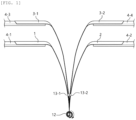
FIG. 2 illustrates a manufacturing apparatus of an electrode assembly according to an embodiment of the present invention. -
FIG. 3 illustrates image data acquired through a machine vision included inFIG. 2 . -
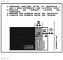
FIG. 4 is a schematic view of computing meandering by accumulating and processing the data ofFIG. 3 . -
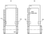
FIG. 5 is a schematic view related to manufacturing of the electrode assembly according to an embodiment of the present invention. - The present invention may have various modifications and various embodiments and specific embodiments will be illustrated in the drawings and described in detail in the detailed description. However, this does not limit the present invention to specific embodiments, and it should be understood that the present disclosure covers all the modifications, equivalents and replacements included within the technical spirit and technical scope of the present invention.
- In the present specification, terms including as first, second, A, B, and the like are used for describing various constituent elements, but the constituent elements are not limited by the terms. The terms are used only to discriminate one element from another element. For example, a first component may be referred to as a second component, and similarly, the second component may be referred to as the first component without departing from the scope of the present invention.
- In the present specification, a term "and/or" includes a combination of a plurality of related items or some of the plurality of related items.
- In the present specification, when a certain component is expressed as a singular number, the certain component may include a plurality of concepts even though is not separately specified in the present specification.
- In the present specification, in respect to terms such as "include", "have", etc., unless separately specified in the present specification, a feature, a number, a step, an operation, a process, a component, a member, etc., or a combination thereof mean an existence itself, and does not mean excluding another feature, another number, etc.
- In the present specification, "secondary battery" refers to a battery which is repeatedly usable for a long time through recharging. The secondary battery may be categorized into a nickel-cadmium battery, a lithium-ion secondary battery, etc., according to an electrode active material. The secondary battery may be categorized into a pouch type secondary battery, a square type secondary battery, a cylindrical secondary battery, etc., according to a type.
- In the present specification, the secondary battery may include a battery can receiving an electrode assembly. The battery can may be cylindrical.
- In the present specification, the term "cylindrical secondary battery" refers to a secondary battery having a cylinder shape or a type similar thereto. The cylindrical secondary battery which is generally used for large-capacity electronic and electric devices due to a characteristic in which energy density per volume is high may be used in a form in which a plurality of cylindrical secondary batteries are combined to constitute a battery pack.
- In the present specification, the cylindrical secondary battery may refer to, for example, a structure in which a rivet penetrated and inserted into a bottom surface opposite to the opening portion of the cylindrical secondary battery is used as a negative electrode and a battery can itself is used as a positive electrode.
- In the present specification, the secondary battery may include a battery can receiving an electrode assembly. The battery can may be cylindrical, and in respect to a size of the battery can, circular diameters of both end portions may be 30 to 55 mm and a height may be 60 to 120 mm. For example, the circular diameter x the height of the cylindrical battery can may be 46 mm x 60 mm, 46 mm x 80 mm, or 46 mm x 90 mm, or 46 mm x 120 mm.
- Preferably, the cylindrical secondary battery may be, for example, a cylindrical secondary battery in which a ratio of a form factor (defined as a value acquired by dividing the diameter of the cylindrical secondary battery by the height, i.e., a ratio of a diameter Φ to a height H) is larger than approximately 0.4.
- The present specification, the term "cylindrical secondary battery" may be, for example, a 46110 cell, a 48750 cell, a 48110 cell, a 48800 cell, and a 46800 cell. In a numerical value representing the form factor, two preceding numbers represents the diameter of the cell, two subsequent numbers represent the height of the cell, and the last number 0 represent that a cross section of the cell is circular. When the height of the cell is 100 mm or more, three numbers are required to represent the height of the cell, and as a result, a last number, 0 is omittable.
- The cylindrical secondary battery according to the present specification, for example, as a substantially cylinder shape cell may be a cylindrical secondary battery in which the diameter is approximately 46 mm, the height is approximately 110 mm, and the ratio of the form factor is approximately 0.418.
- The cylindrical secondary battery according to the present specification, for example, as a substantially cylinder shape cell may be a battery cell in which the diameter is approximately 48mm, the height is approximately 75mm, and the ratio of the form factor is approximately 0.640.
- The cylindrical secondary battery according to the present specification, for example, as a substantially cylinder shape cell may be a cylindrical secondary battery in which the diameter is approximately 48mm, the height is approximately 110 mm, and the ratio of the form factor is approximately 0.418.
- The cylindrical secondary battery according to the present specification, for example, as a substantially cylinder shape cell may be a battery cell in which the diameter is approximately 48mm, the height is approximately 80mm, and the ratio of the form factor is approximately 0.600.
- The cylindrical secondary battery according to the present specification, for example, as a substantially cylinder shape cell may be a battery cell in which the diameter is approximately 46mm, the height is approximately 80mm, and the ratio of the form factor is approximately 0.575.
- The cylindrical secondary battery according to the present specification, for example, as a substantially cylinder shape cell may be a cylindrical secondary battery in which the diameter is approximately 46 mm, the height is approximately 90 mm, and the ratio of the form factor is 0.511.
- Further, a terminology "first electrode" refers to a negative electrode (or anode) and a terminology "second electrode" refers to the positive electrode (or cathode), but vice versa.
- If it is not contrarily defined, all terms used herein including technological or scientific terms have the same meanings as those generally understood by a person with ordinary skill in the art.
- Hereinafter, the related art and a preferred embodiment of the present invention will be described in detail with reference to the accompanying drawings.
- Referring to
FIG. 1 , a conventional manufacturing apparatus of an electrode assembly is illustrated, and a windingcore 12 is wound while rotating clockwise, and here, afirst electrode 1, a first separator 3-1, asecond electrode 2, and a second separator 3-2 move to the windingcore 12, and an EPS 13-1 that measures a non-overlap width for thefirst electrode 1 and the first separator 3-1 and an EPS 13-2 that measures the non-overlap width for thesecond electrode 2 and the second separator 3-2 are installed. EPS as an abbreviation of edge position sensor is installed on a front end of a driving distance of an electrode (first electrode and second electrode) and a separator (first separator and second separator) on a width-direction end portion of the electrode or the separator to serve to measure a location of each of the electrode and the separator. Here, a worker observes the non-overlap width of thefirst electrode 1 and the first separator 3-1 and the non-overlap width of thesecond electrode 2 and the second separator 3-2 from two EPSs 13-1 and 13-2, and the worker calculates a meandering reference value by personally performing measurement, judgment, and computation steps in order to adjust meandering by combing values of the non-overlap widths. However, a human error occurs in each step, and when the worker mis-inputs the meandering reference value, a problem in that even a case of a meandering defect is judged as an adequate product also occurs. - According to one implementation example of the present invention, provided is a manufacturing apparatus of an electrode assembly, which includes:
- a first machine vision provided on a driving-direction front end of a first electrode from a winding core and measuring a first non-overlap width between one width-direction end portion of the first electrode and one width-direction end portion of a first separator, and a second machine vision provided on a driving-direction front end of a second electrode from the winding core, and measuring a second non-overlap width between one width-direction end portion of a second electrode and one width-direction end portion of a second separator;
- a control unit collecting vision data obtained from the first machine vision and the second machine vision, setting a non-overlap width between the first separator and the second separator to 0 through vision data, computing a third non-overlap width between the width-direction end portion of the first electrode and the width-direction end portion of the second electrode, and judging a meandering defect with the computed third non-overlap width;
- a data processing unit accumulating and processing defect judgment data through machine learning; and
- an input unit automatically inputting a meandering reference value based on the data processed by the data processing unit.
- In regard to the implementation example, referring to
FIG. 2 , first and second machine visions 8-1 and 8-2 are provided on driving-direction front ends of theelectrodes first electrode 1 and the width-direction end portion of the first separator 3-1, and the second machine vision 8-2 measures a second non-overlap width between the width-direction end portion of thesecond electrode 2 and the width-direction end portion of the second separator 3-2. - In the implementation example, "width direction" means a direction of a short side in each of the first electrode, the second electrode, the first separator, and the second separator. In general, the width direction means a direction orthogonal to a length direction.
- Further, the vision data which the control unit 9 acquires from the first machine vision 8-1 and the second machine vision 8-2 is illustrated in
FIG. 3 . Further, referring toFIG. 4 , a reference line in which the non-overlap width between the first separator 3-1 and the second separator 3-2 is set to 0, and the third non-overlap width between the width-direction end portion of thefirst electrode 1 and the width-direction end portion of thesecond electrode 2 is computed through the first non-overlap width and the second non-overlap width. - Further, the control unit 9 judges whether the computed third non-overlap width is defective, the
data processing unit 10 accumulates and processes the defect judgment data through the machine learning, and theinput unit 11 automatically inputs the meandering reference value (a width of at least one of the first electrode, the second electrode, the first separator, and the second separator) based on the data processed by thedata processing unit 10. - In the manufacturing apparatus of the electrode assembly according to the implementation example, the non-overlap width may be measured in real time by installing the machine vision on the driving-direction front ends of the electrode and the separator, since the meandering reference value is automatically input while the defect judgment data is accumulated and processed through the machine learning, the non-overlap width is measured by the worker and it is judged whether the non-overlap width is defective, and an effect of minimizing a human error which occurs as the meandering reference value is automatically input is provided.
- According to an additional implementation example, provided is the manufacturing apparatus of the electrode assembly, which further includes one or all of a third machine vision provided on the driving-direction front end of the first electrode from the winding core and inspecting at least one of a bending of a first electrode coating edge and a first electrode tab of the other width-direction end portion of the first electrode, and
a fourth machine vision provided on the driving-direction front end of the second electrode from the winding core and inspecting at least one of a bending of a second electrode coating edge and a second electrode tab of the other width-direction end portion of the second electrode. - In regard to the implementation example, referring to
FIGS. 2 and5 , a third machine vision 8-3 is disposed beside the first machine vision 8-1 and a fourth machine vision 8-4 is disposed beside the second machine vision 8-2. In the jelly-roll electrode assembly 100, the first machine vision 8-1 measures a firstnon-overlap width 110 between one width-direction end portion of the first electrode and one width-direction end portion of the first separator and the second machine vision 8-2 measures a secondnon-overlap width 130 between one width-direction end portion of the second electrode and one width-direction end portion of the second separator. Further, the third machine vision 8-3 inspects at least one of a bending of a firstelectrode coating edge 120 and a first electrode tab of the other width-direction end portion of the first electrode and the fourth machine vision 8-4 inspects at least one of a bending of a secondelectrode coating edge 140 and a second electrode tab of the other width-direction end portion of the second electrode. Selectively, the fourth machine vision may inspect alignment between the first separator 3-1 and the second separator 3-2. - According to an additional implementation example, provided is the manufacturing apparatus of the electrode assembly, which includes a first guide roller guiding the first electrode and the first separator to be in contact with each other at a portion spaced apart from the winding core by 5 to 60 mm or less, and a second guide roller guiding the second electrode and the second separator to be in contact with each other.
- Selectively, each of the first guide roller and the second guide roller may be independently installed at a portion spaced apart from the winding core by 5 mm or more, 10 mm or more, 15 mm or more, 20 mm or more, 25 mm, or 30 mm or more. Alternatively, each of the first guide roller and the second guide roller may be independently installed at a portion spaced apart from the winding core by 60 mm or less, 55 mm or less, 50 mm or less, 45 mm or less, 40 mm, or 35 mm or less.
- In regard to the implementation example, referring to
FIG. 2 , a first guide roller 5-1 and a second guide roller 5-2 are independently installed at a portion spaced apart from a windingcore 12 by 5 to 60 mm or less so that the first electrode and the first separator are in contact with each other. The first guide roller 5-1 guides thefirst electrode 1 and the first separator 3-1 to be in contact with each other and the second guide roller 5-2 guides thesecond electrode 2 and the second separator 3-2 to be in contact with each other. - The manufacturing apparatus of the electrode assembly according to the implementation example provides an effect of accurately measuring the first non-overlap width of the first electrode and the first separator and the second non-overlap width of the second electrode and the second separator.
- According to an additional implementation example, provided is the manufacturing apparatus of the electrode assembly, which further includes: a supply line of the first electrode, the supply line of the first separator, the supply line of the second electrode, and the supply line of the second separator; and
a winding core rotating and winding one length-direction end portion while fixing one length-direction end portion of each of the first electrode, the first separator, the second electrode, and the second separator. - In regard to the implementation example, referring to
FIG. 2 , thefirst electrode 1 is supplied through a supply line 4-1 of the first electrode, thesecond electrode 2 is supplied through a supply line 4-2 of the second electrode, the first separator 3-1 is supplied through a supply line 4-3 of the first separator, and a second separator 3-2 is supplied through a supply line 4-4 of the second separator. - The winding
core 12 is rotated while fixing a length-direction end portion of each of thefirst electrode 1, the first separator 3-1, thesecond electrode 2, and the second separator 3-2 to the windingcore 12 to wind the length-direction end portion. - Selectively, the winding
core 12 may be rotated in a clockwise direction or a counterclockwise direction. - Further, in the implementation example, "length direction" means a direction of a long side in each of the first electrode, the second electrode, the first separator, and the second separator.
- According to an additional implementation example, provided is the manufacturing apparatus of the electrode assembly, which further includes a feed motor that is provided between each of the supply line of the first electrode, the supply line of the first separator, the supply line of the second electrode, and the supply line of the second separator, and the winding core, and inputs each of the first electrode, the first separator, the second electrode, and the second separator into the winding core.
- In regard to the implementation example, referring to
FIG.2 , the length-direction end portion is wound by rotating the windingcore 12 while fixing the length-direction end portion of each of thefirst electrode 1, the first separator 3-1, thesecond electrode 2, and the second separator 3-2 to the windingcorer 12, and thefirst electrode 1, the first separator 3-1, thesecond electrode 2, and the second separator 3-2 is input into the windingcore 12 by using a feed motor 6.
According to an additional implementation example, provided is the manufacturing apparatus of the electrode assembly, which further includes a third guide roller that is provided between each of the supply line of the first electrode, the supply line of the first separator, the supply line of the second electrode, and the supply line of the second separator, and the feed motor to move to the feed motor from the supply line of the first electrode, the supply line of the first separator, the supply line of the second electrode, and the supply line of the second separator. - In regard to the implementation example, referring to
FIG. 2 , a third guide roller 5-3 allows thefirst electrode 1, thesecond electrode 2, the first separator 3-1, and the second separator 3-2 to be smoothly bent to a feed motor 6 from respective supply lines 4-1 to 4-4. - According to one implementation example, provided is the manufacturing apparatus of the electrode assembly, which further includes a cutter that is provided between the wining core and the feed motor, and cutting an electrode assembly input into the winding core.
- Referring to
FIG. 2 , a cutter (not illustrated) is disposed between the windingcore 12 and the feed motor 6 to serve to cut the electrode assembly. - According to one implementation example, provided is a manufacturing apparatus of the electrode assembly in which the cutter glides between the winding core and the feed motor.
- According to the implementation example, since the cutter is a glidable model, terminals of the electrode and/or the separator may be controlled by adjusting a cutting location.
- In regard to the implementation example, referring to
FIG. 2 , the cutter (not illustrated) is movable between the windingcore 12 and the feed motor 6 to serve to cut the electrode assembly. - According to an additional implementation example, provided is the manufacturing apparatus of the electrode assembly, which includes an illumination between the feed motor and the first machine vision and/or the second machine vision.
- According to an additional implementation example, the illumination may be a constant current type and/or a bar type.
- According to an implementation example, provided is the manufacturing apparatus of the electrode assembly in which the illumination is the bar type illumination.
- In regard to the implementation examples, referring to
FIG. 2 , an illumination 7 is disposed between the feed motor 6 and the first machine vision 8-1 and/or the second machine vision 8-2. - The manufacturing apparatus of the electrode assembly according to the implementation example provides an effect of providing a stable image to the machine vision.
- According to an additional implementation example, provided is the manufacturing apparatus of the electrode assembly in which the illumination is installed at a portion a spaced part from the winding core by a distance of 130 to 170 mm.
- According to an additional implementation example, the illumination 7 may be installed at a portion spaced apart from the winding
core 12 by a distance of 130 mm or more, 135 mm or more, 140 mm or more, or 145 mm or more. - According to an additional implementation example, the illumination 7 may be installed at a portion spaced apart from the winding
core 12 by a distance of 170 mm or less, 165 mm or less, 160 mm or less, or 155 mm or less. - According to an additional implementation example, the illumination 7 may be installed at a portion spaced apart from the winding
core 12 by a distance of 150 mm. - According to an additional implementation example, provided is the manufacturing apparatus of the electrode assembly in which measurement portions of the first machine vision and the second machine vision are spaced apart from the winding core by 1 to 50 mm.
- According to an additional implementation example, the measurement portions of the first machine vision 8-1 and the second machine vision 8-2 may be spaced apart from the winding
core 12 by 1 mm or more, 5 mm or more, 10 mm or more, or 15 mm or more. - According to an additional implementation example, the measurement portions of the first machine vision and the second machine vision may be spaced apart from the winding
core 12 by 50 mm or less, 45 mm or less, 40 mm less, 35 mm or less, 30 mm or less, or 25 mm or less. - According to an additional implementation example, the measurement portions of the first machine vision and the second machine vision may be spaced apart from the winding core12 by 20 mm.
- In regard to the implementation example, referring to
FIG. 2 , the measure portions of the first machine vision 8-1 and the second machine vision 8-2 are spaced apart by a proximal region (1 to 50 mm) from the windingcore 12 at driving-direction front end portions of the first electrode, the first separator, the second electrode, and the second separator. - According to the manufacturing apparatus of the electrode assembly according to the implementation example, a system that directly monitors the locations of the electrode and the separator by the worker through the EPS installed in the winding corer portion in the related art is replaced and a region from the winding core by 10 mm or more and 50 mm or less is measured by the machine vision to provide an effect of reducing a human error.
- According to one implementation example, provided is a manufacturing method of an electrode assembly, which includes: (A) measuring a first non-overlap width between one width-direction end portion of the first electrode and one width-direction end portion of a first separator by a first machine vision provided on a driving-direction front end of a first electrode from a winding core, and measuring a second non-overlap width between one width-direction end portion of a second electrode and one width-direction end portion of a second separator by a second machine vision provided on a driving-direction front end of a second electrode;
- (B) collecting vision data obtained from the first machine vision and the second machine vision, setting a non-overlap width between the first separator and the second separator to 0 through vision data, computing a third non-overlap width between the width-direction end portion of the first electrode and the width-direction end portion of the second electrode, and judging a meandering defect with the computed third non-overlap width;
- (C) accumulating and processing defect judgment data through machine learning; and
- (D) automatically inputting a meandering reference value based on the data processed by the data processing unit.
- In step (A), the first machine vision 8-1 is provided on the driving-direction front ends of the
first electrode 1 and the first separator 3-1 and the second machine vision 8-2 is provided on the driving-direction front ends of thesecond electrode 2 and the second separator 3-2. Here, the first machine vision 8-1 measures a first non-overlap width between one width-direction end portion of thefirst electrode 1 and one width-direction end portion of the first separator 3-1, and the second machine vision 8-2 measures a second non-overlap width between one width-direction end portion of thesecond electrode 2 and one width-direction end portion of the second separator 3-2. - Further, the vision data acquired from the first machine vision 8-1 and the second machine vision 8-2 are collected and a result thereof is illustrated in
FIG. 3 . Further, referring toFIG. 4 , a reference line in which the non-overlap width between the first separator 3-1 and the second separator 3-2 is set to 0, and the third non-overlap width between the first non-overlap width-direction end portion and the second non-overlap width direction end portion is computed, and the meandering defect is judged by the computed third non-overlap width. - The defect judgment data is accumulated and processed through the machine learning, and a meandering reference value is automatically input based on the processed data. Here, the meandering reference value may be a width of at least one of the first electrode, the second electrode, the first separator, and the second separator, or at least one of driving velocities and input amounts of the electrode and the separator.
- In the manufacturing method of the electrode assembly according to the implementation example, the non-overlap width may be measured in real time by installing the machine vision on the driving-direction front ends of the electrode and the separator, since the meandering reference value is automatically input while the defect judgment data is accumulated and processed through the machine learning, the non-overlap width is measured by the worker and it is judged whether the non-overlap width is defective, and an effect of minimizing a human error which occurs as the meandering reference value is automatically input is provided.
- According to an additional implementation example, provided is the manufacturing method of the electrode assembly, which further includes, before step (A),
- (A-1) supplying a first electrode, a first separator, a second electrode, and a second separator to a supply line of the first electrode, the supply line of the first separator, the supply line of the second electrode, and the supply line of the second separator, respectively; and
- (A-2) fixing a length-direction end portion of each of the first electrode, the first separator, the second electrode, and the second separator to a winding core.
- Referring to
FIG. 2 , in step (A-1), thefirst electrode 1 is supplied through a supply line 4-1 of the first electrode, thesecond electrode 2 is supplied through a supply line 4-2 of the second electrode, the first separator 3-1 is supplied through a supply line 4-3 of the first separator, and a second separator 3-2 is supplied through a supply line 4-4 of the second separator. - In step (A-2), the length-direction end portion of each of the
first electrode 1, the first separator 3-1, thesecond electrode 2, and the second separator 3-2 is fixed to the windingcore 12. - Concrete contents regarding the manufacturing method of the electrode assembly according to the implementation example are described as above.
- According to an additional implementation example, provided is the manufacturing method of the electrode assembly, in which step (B) further includes one or all of
- (B-1) inspecting, by a third machine vision provided on the driving-direction front end of the first electrode from the winding core, at least one of a bending of a first electrode coating edge and a first electrode tab of the other width-direction end portion of the first electrode, and
- (B-2) inspecting, by a fourth machine vision provided on the driving-direction front end of the second electrode from the winding core, at least one of a bending of a second electrode coating edge and a second electrode tab of the other width-direction end portion of the second electrode.
- Concrete contents regarding the manufacturing method of the electrode assembly according to the implementation example are described as above.
- Although the preferred examples of the present invention are described through the above description, but the present invention is not limited thereto and various medications can be made within the claims and the range the detailed description of the invention, and this also belongs to the scope of the present invention.
-
- 1: First electrode
- 2: Second electrode
- 3-1: First separator
- 3-2: Second separator
- 4-1: Supply line of first electrode
- 4-2: Supply line of second electrode
- 4-3: Supply line of first separator
- 4-4: Supply line of second separator
- 5-1: First guide roller
- 5-2: Second guide roller
- 5-3: Third guide roller
- 6: Feed motor
- 7: Illumination
- 8-1: First machine vision
- 8-2: Second machine vision
- 8-3: Third machine vision
- 8-4: Fourth machine vision
- 9: Control unit
- 10: Data processing unit
- 11: Input unit
- 12: Winding core
- 13-1, 13-2: Edge Position Sensor (EPS)
- 100: Jelly-roll electrode assembly
- 110: First non-overlap width
- 120: First electrode coating edge
- 130: Second non-overlap width
- 140: Second electrode coating edge
Claims (15)
- A manufacturing apparatus of an electrode assembly, comprising:a first machine vision provided on a driving-direction front end of a first electrode from a winding core, the first machine vision being configured to measure a first non-overlap width between a first width-direction end portion of the first electrode and a first width-direction end portion of a first separator;a second machine vision provided on a driving-direction front end of a second electrode from the winding core, the second machine vision being configured to measure a second non-overlap width between a first width-direction end portion of a second electrode and a first width-direction end portion of a second separator;a controller configured to:collect vision data obtained from the first machine vision and the second machine vision;set a non-overlap width between the first separator and the second separator to 0 through vision data;compute a third non-overlap width between the first width-direction end portion of the first electrode and the first width-direction end portion of the second electrode; andjudge a meandering defect with the computed third non-overlap width;a data processing unit configured to accumulate and process defect judgment data through machine learning; andan input unit configured to automatically input a meandering reference value based on the data processed by the data processing unit.
- The manufacturing apparatus of an electrode assembly of claim 1, further comprising at least one of:a third machine vision provided on the driving-direction front end of the first electrode from the winding core, the third machine vision being configured to inspect at least one of a bending of a first electrode coating edge and a first electrode tab of a second width-direction end portion of the first electrode; anda fourth machine vision provided on the driving-direction front end of the second electrode from the winding core, the fourth machine vision being configured to inspect at least one of a bending of a second electrode coating edge and a second electrode tab of a second width-direction end portion of the second electrode.
- The manufacturing apparatus of an electrode assembly of claim 1, further comprising:a first guide roller configured to guide the first electrode and the first separator to be in contact with each other at a location spaced apart from the winding core by 5 to 60 mm; anda second guide roller configured to guide the second electrode and the second separator to be in contact with each other.
- The manufacturing apparatus of an electrode assembly of claim 1, further comprising:a supply line of the first electrode, a supply line of the first separator, a supply line of the second electrode, and a supply line of the second separator; anda winding core configured to rotate while fixing a first length-direction end portion of each of the first electrode, the first separator, the second electrode, and the second separator to wind the first electrode, the first separator, the second electrode, and the second separator.
- The manufacturing apparatus of an electrode assembly of claim 4, further comprising a feed motor between the winding core and each of the supply line of the first electrode, the supply line of the first separator, the supply line of the second electrode, and the supply line of the second separator, and the winding core, to input each of the first electrode, the first separator, the second electrode, and the second separator into the winding core.
- The manufacturing apparatus of an electrode assembly of claim 5, further comprising a third guide roller between each of the feed motors and the supply line of the first electrode, the supply line of the first separator, the supply line of the second electrode, and the supply line of the second separator.
- The manufacturing apparatus of an electrode assembly of claim 5, further comprising a cutter between the winding core and the motors to cut the electrode assembly input into the winding core.
- The manufacturing apparatus of an electrode assembly of claim 7, wherein the cutter glides between the winding core and the feed motors.
- The manufacturing apparatus of an electrode assembly of claim 5, further comprising an illuminator between the feed motors and the first machine vision and the second machine vision.
- The manufacturing apparatus of an electrode assembly of claim 9, wherein the illuminator is a constant current mode bar type illuminator.
- The manufacturing apparatus of an electrode assembly of claim 9, wherein the illuminator is installed at a location spaced apart from the winding core by 130 to 170 mm.
- The manufacturing apparatus of an electrode assembly of claim 1, wherein measurement portions of the first machine vision and the second machine vision are spaced apart from the winding core by 10 to 50 mm.
- A manufacturing method of an electrode assembly, comprising:measuring a first non-overlap width between a first width-direction end portion of a first electrode and a first width-direction end portion of a first separator by a first machine vision provided on a driving-direction front end of the first electrode from a winding core;measuring a second non-overlap width between a first width-direction end portion of a second electrode and a first width-direction end portion of a second separator by a second machine vision provided on a driving-direction front end the second electrode;collecting vision data obtained from the first machine vision and the second machine vision by a controller;setting a non-overlap width between the first separator and the second separator to 0 through vision data by the controller;computing a third non-overlap width between the first width-direction end portion of the first electrode and the first width-direction end portion of the second electrode by the controller; andjudging a meandering defect with the computed third non-overlap by the controller;accumulating and processing defect judgment data through machine learning by a data processing unit; andautomatically inputting a meandering reference value based on the data processed by the data processing unit.
- The manufacturing method of an electrode assembly of claim 13, further comprising, before measuring the first non-overlap width:supplying the first electrode, the first separator, the second electrode, and the second separator to a supply line of the first electrode, a supply line of the first separator, a supply line of the second electrode, and a supply line of the second separator, respectively; andfixing a length-direction end portion of each of the first electrode, the first separator, the second electrode, and the second separator to the winding core.
- The manufacturing method of an electrode assembly of claim 13, wherein collecting the vision data obtained from the first machine vision and the second machine vision includes at least one of:inspecting, by a third machine vision provided on the driving-direction front end of the first electrode from the winding core, at least one of a bending of a first electrode coating edge and a first electrode tab of a second width-direction end portion of the first electrode, andinspecting, by a fourth machine vision provided on the driving-direction front end of the second electrode from the winding core, at least one of a bending of a second electrode coating edge and a second electrode tab of a second width-direction end portion of the second electrode.
Applications Claiming Priority (2)
| Application Number | Priority Date | Filing Date | Title |
|---|---|---|---|
| KR20210030407 | 2021-03-08 | ||
| PCT/KR2022/003054 WO2022191510A1 (en) | 2021-03-08 | 2022-03-03 | Electrode assembly manufacturing device and electrode assembly manufacturing method |
Publications (3)
| Publication Number | Publication Date |
|---|---|
| EP4307416A1 true EP4307416A1 (en) | 2024-01-17 |
| EP4307416A4 EP4307416A4 (en) | 2025-04-30 |
| EP4307416B1 EP4307416B1 (en) | 2026-05-13 |
Family
ID=83226904
Family Applications (1)
| Application Number | Title | Priority Date | Filing Date |
|---|---|---|---|
| EP22767406.6A Active EP4307416B1 (en) | 2021-03-08 | 2022-03-03 | Electrode assembly manufacturing device and electrode assembly manufacturing method |
Country Status (6)
| Country | Link |
|---|---|
| US (1) | US20240313252A1 (en) |
| EP (1) | EP4307416B1 (en) |
| JP (1) | JP7625330B2 (en) |
| KR (1) | KR102815846B1 (en) |
| CN (1) | CN220895561U (en) |
| WO (1) | WO2022191510A1 (en) |
Families Citing this family (3)
| Publication number | Priority date | Publication date | Assignee | Title |
|---|---|---|---|---|
| EP4571243A4 (en) * | 2022-12-20 | 2026-05-06 | Lg Energy Solution Ltd | DEVICE FOR INSPECTING AN ELECTRODE ASSEMBLY AND BATTERY CELL WITH AN ELECTRODE ASSEMBLY MADE WITH IT, AS WELL AS A BATTERY PACK AND VEHICLE WITH BATTERY CELLS |
| KR20240109136A (en) * | 2023-01-03 | 2024-07-10 | 주식회사 엘지에너지솔루션 | Monitoring device and operating method thereof |
| DE102023200459B4 (en) * | 2023-01-20 | 2025-05-28 | Powerco Se | Method for determining a position of a corner region of an electrode composite stack |
Family Cites Families (13)
| Publication number | Priority date | Publication date | Assignee | Title |
|---|---|---|---|---|
| JPS63188916A (en) * | 1987-01-31 | 1988-08-04 | Kitamura Kiden Kk | System for controlling travel position of band material |
| US6026563A (en) * | 1996-04-03 | 2000-02-22 | Methode Electronics, Inc. | Method of making flat cable |
| JP4716138B2 (en) * | 2008-01-11 | 2011-07-06 | トヨタ自動車株式会社 | Electrode winding device, deviation detection method between band electrode and band separator, deviation amount measuring method, deviation amount correcting method, and electrode winding method |
| JP5279533B2 (en) * | 2009-01-30 | 2013-09-04 | 日立ビークルエナジー株式会社 | Lithium ion battery and method for producing lithium ion battery |
| JP6246684B2 (en) * | 2014-09-08 | 2017-12-13 | Ckd株式会社 | Inspection device and winding device |
| CN107112578B (en) * | 2015-01-13 | 2019-07-05 | 艾利电力能源有限公司 | The positional shift detection method and its device of electrode plate in electrode laminated body |
| JP6607406B2 (en) * | 2016-10-13 | 2019-11-20 | トヨタ自動車株式会社 | Winding electrode body manufacturing equipment |
| JP6676572B2 (en) * | 2017-03-29 | 2020-04-08 | Ckd株式会社 | Inspection device and winding device |
| KR102558461B1 (en) * | 2018-06-20 | 2023-07-24 | 주식회사 엘지에너지솔루션 | Manufacturing method and apparatus for electrode stack |
| CN112399987A (en) | 2018-07-10 | 2021-02-23 | 切卢特克股份公司 | Porous materials of cellulose fibres and gluten |
| KR102544744B1 (en) * | 2019-03-12 | 2023-06-16 | 주식회사 엘지에너지솔루션 | Lamination apparatus and method for secondary battery |
| JP7437784B2 (en) * | 2019-04-22 | 2024-02-26 | パナソニックIpマネジメント株式会社 | Trained model generation method, maintenance display device, and program |
| KR102757891B1 (en) * | 2019-11-13 | 2025-01-22 | 주식회사 엘지에너지솔루션 | Electrode assembly manufacturing method and electrode assembly manufactured manufacturing device |
-
2022
- 2022-03-03 JP JP2023535067A patent/JP7625330B2/en active Active
- 2022-03-03 WO PCT/KR2022/003054 patent/WO2022191510A1/en not_active Ceased
- 2022-03-03 CN CN202290000238.2U patent/CN220895561U/en active Active
- 2022-03-03 US US18/267,043 patent/US20240313252A1/en active Pending
- 2022-03-03 KR KR1020220027749A patent/KR102815846B1/en active Active
- 2022-03-03 EP EP22767406.6A patent/EP4307416B1/en active Active
Also Published As
| Publication number | Publication date |
|---|---|
| JP7625330B2 (en) | 2025-02-03 |
| WO2022191510A1 (en) | 2022-09-15 |
| US20240313252A1 (en) | 2024-09-19 |
| JP2023553923A (en) | 2023-12-26 |
| CN220895561U (en) | 2024-05-03 |
| KR20220126223A (en) | 2022-09-15 |
| EP4307416A4 (en) | 2025-04-30 |
| EP4307416B1 (en) | 2026-05-13 |
| KR102815846B1 (en) | 2025-06-02 |
Similar Documents
| Publication | Publication Date | Title |
|---|---|---|
| EP4307416B1 (en) | Electrode assembly manufacturing device and electrode assembly manufacturing method | |
| KR102465777B1 (en) | Manufacturing method and apparatus for electrode stack | |
| EP3621140B1 (en) | Apparatus and method for manufacturing secondary battery | |
| US11597115B2 (en) | Apparatus and method for cutting electrode sheet | |
| KR102259235B1 (en) | multi-type secondary battery stacking device having vision inspection | |
| KR101223629B1 (en) | Winding apparatus, miss winding inspection system, and miss winding inspection method | |
| JPWO2012023422A1 (en) | Electrode winding method and electrode winding apparatus | |
| US12358746B2 (en) | Automatic electrode supply apparatus for manufacture of secondary battery and automatic electrode supply method using the same | |
| KR20190143253A (en) | Manufacturing method and apparatus for electrode stack | |
| JP7669506B2 (en) | Electrode sheet skew correction method, device, equipment, storage medium and product | |
| KR102219019B1 (en) | Secondary battery electrode track adjustment system and electrode track adjustment method thereby | |
| EP4421479B1 (en) | Image collection apparatus and electrode sheet defect detection system | |
| CN104733769A (en) | Manufacturing method of all-solid battery | |
| WO2025097942A1 (en) | Material strip detection method and die cutter | |
| EP4105154A1 (en) | Automated electrode roll connection device | |
| EP3723185A1 (en) | Method for enhancing a battery module model of a battery module type | |
| CN121272504A (en) | Copper foil production system and method | |
| KR101810144B1 (en) | Apparatus for pressing and slitting electrode of secondary battery | |
| EP4321836B1 (en) | Measurement device and electrode plate production system | |
| KR20210071363A (en) | Winding device and diameter measuring method for measuring the diameter of the jelly roll | |
| EP4498034A1 (en) | Secondary battery sealing gap measurement equipment and measurement method | |
| EP4343903A1 (en) | Electrode cutting device and cell manufacturing device comprising same | |
| CN116918114A (en) | Electrode blade cutting device and method | |
| KR102786227B1 (en) | apparatus and method for cutting electrode materials of laminating process of secondary battery | |
| EP4432452B1 (en) | Notching device and control method thereof |
Legal Events
| Date | Code | Title | Description |
|---|---|---|---|
| STAA | Information on the status of an ep patent application or granted ep patent |
Free format text: STATUS: THE INTERNATIONAL PUBLICATION HAS BEEN MADE |
|
| PUAI | Public reference made under article 153(3) epc to a published international application that has entered the european phase |
Free format text: ORIGINAL CODE: 0009012 |
|
| STAA | Information on the status of an ep patent application or granted ep patent |
Free format text: STATUS: REQUEST FOR EXAMINATION WAS MADE |
|
| 17P | Request for examination filed |
Effective date: 20230608 |
|
| AK | Designated contracting states |
Kind code of ref document: A1 Designated state(s): AL AT BE BG CH CY CZ DE DK EE ES FI FR GB GR HR HU IE IS IT LI LT LU LV MC MK MT NL NO PL PT RO RS SE SI SK SM TR |
|
| DAV | Request for validation of the european patent (deleted) | ||
| DAX | Request for extension of the european patent (deleted) | ||
| A4 | Supplementary search report drawn up and despatched |
Effective date: 20250402 |
|
| RIC1 | Information provided on ipc code assigned before grant |
Ipc: G01N 21/89 20060101ALI20250327BHEP Ipc: G01N 21/892 20060101ALI20250327BHEP Ipc: B65H 26/02 20060101ALI20250327BHEP Ipc: G01N 21/88 20060101ALI20250327BHEP Ipc: G01N 21/93 20060101ALI20250327BHEP Ipc: H01M 10/04 20060101AFI20250327BHEP |
|
| GRAP | Despatch of communication of intention to grant a patent |
Free format text: ORIGINAL CODE: EPIDOSNIGR1 |
|
| STAA | Information on the status of an ep patent application or granted ep patent |
Free format text: STATUS: GRANT OF PATENT IS INTENDED |
|
| INTG | Intention to grant announced |
Effective date: 20260115 |
|
| GRAS | Grant fee paid |
Free format text: ORIGINAL CODE: EPIDOSNIGR3 |
|
| GRAA | (expected) grant |
Free format text: ORIGINAL CODE: 0009210 |
|
| STAA | Information on the status of an ep patent application or granted ep patent |
Free format text: STATUS: THE PATENT HAS BEEN GRANTED |
|
| AK | Designated contracting states |
Kind code of ref document: B1 Designated state(s): AL AT BE BG CH CY CZ DE DK EE ES FI FR GB GR HR HU IE IS IT LI LT LU LV MC MK MT NL NO PL PT RO RS SE SI SK SM TR |
|
| REG | Reference to a national code |
Ref country code: CH Ref legal event code: F10 Free format text: ST27 STATUS EVENT CODE: U-0-0-F10-F00 (AS PROVIDED BY THE NATIONAL OFFICE) Effective date: 20260513 |