EP4307415A1 - Battery cell and electrical device - Google Patents
Battery cell and electrical device Download PDFInfo
- Publication number
- EP4307415A1 EP4307415A1 EP21935605.2A EP21935605A EP4307415A1 EP 4307415 A1 EP4307415 A1 EP 4307415A1 EP 21935605 A EP21935605 A EP 21935605A EP 4307415 A1 EP4307415 A1 EP 4307415A1
- Authority
- EP
- European Patent Office
- Prior art keywords
- battery cell
- tab
- sealing
- cavity
- cell according
- Prior art date
- Legal status (The legal status is an assumption and is not a legal conclusion. Google has not performed a legal analysis and makes no representation as to the accuracy of the status listed.)
- Pending
Links
Images







Classifications
-
- H—ELECTRICITY
- H01—ELECTRIC ELEMENTS
- H01M—PROCESSES OR MEANS, e.g. BATTERIES, FOR THE DIRECT CONVERSION OF CHEMICAL ENERGY INTO ELECTRICAL ENERGY
- H01M50/00—Constructional details or processes of manufacture of the non-active parts of electrochemical cells other than fuel cells, e.g. hybrid cells
- H01M50/10—Primary casings; Jackets or wrappings
- H01M50/183—Sealing members
- H01M50/184—Sealing members characterised by their shape or structure
-
- H—ELECTRICITY
- H01—ELECTRIC ELEMENTS
- H01M—PROCESSES OR MEANS, e.g. BATTERIES, FOR THE DIRECT CONVERSION OF CHEMICAL ENERGY INTO ELECTRICAL ENERGY
- H01M50/00—Constructional details or processes of manufacture of the non-active parts of electrochemical cells other than fuel cells, e.g. hybrid cells
- H01M50/50—Current conducting connections for cells or batteries
- H01M50/531—Electrode connections inside a battery casing
-
- H—ELECTRICITY
- H01—ELECTRIC ELEMENTS
- H01M—PROCESSES OR MEANS, e.g. BATTERIES, FOR THE DIRECT CONVERSION OF CHEMICAL ENERGY INTO ELECTRICAL ENERGY
- H01M10/00—Secondary cells; Manufacture thereof
- H01M10/04—Construction or manufacture in general
- H01M10/0431—Cells with wound or folded electrodes
-
- H—ELECTRICITY
- H01—ELECTRIC ELEMENTS
- H01M—PROCESSES OR MEANS, e.g. BATTERIES, FOR THE DIRECT CONVERSION OF CHEMICAL ENERGY INTO ELECTRICAL ENERGY
- H01M4/00—Electrodes
- H01M4/02—Electrodes composed of, or comprising, active material
- H01M4/04—Processes of manufacture in general
-
- H—ELECTRICITY
- H01—ELECTRIC ELEMENTS
- H01M—PROCESSES OR MEANS, e.g. BATTERIES, FOR THE DIRECT CONVERSION OF CHEMICAL ENERGY INTO ELECTRICAL ENERGY
- H01M50/00—Constructional details or processes of manufacture of the non-active parts of electrochemical cells other than fuel cells, e.g. hybrid cells
- H01M50/10—Primary casings; Jackets or wrappings
- H01M50/102—Primary casings; Jackets or wrappings characterised by their shape or physical structure
- H01M50/105—Pouches or flexible bags
-
- H—ELECTRICITY
- H01—ELECTRIC ELEMENTS
- H01M—PROCESSES OR MEANS, e.g. BATTERIES, FOR THE DIRECT CONVERSION OF CHEMICAL ENERGY INTO ELECTRICAL ENERGY
- H01M50/00—Constructional details or processes of manufacture of the non-active parts of electrochemical cells other than fuel cells, e.g. hybrid cells
- H01M50/10—Primary casings; Jackets or wrappings
- H01M50/172—Arrangements of electric connectors penetrating the casing
- H01M50/174—Arrangements of electric connectors penetrating the casing adapted for the shape of the cells
- H01M50/178—Arrangements of electric connectors penetrating the casing adapted for the shape of the cells for pouch or flexible bag cells
-
- H—ELECTRICITY
- H01—ELECTRIC ELEMENTS
- H01M—PROCESSES OR MEANS, e.g. BATTERIES, FOR THE DIRECT CONVERSION OF CHEMICAL ENERGY INTO ELECTRICAL ENERGY
- H01M50/00—Constructional details or processes of manufacture of the non-active parts of electrochemical cells other than fuel cells, e.g. hybrid cells
- H01M50/50—Current conducting connections for cells or batteries
- H01M50/531—Electrode connections inside a battery casing
- H01M50/533—Electrode connections inside a battery casing characterised by the shape of the leads or tabs
-
- H—ELECTRICITY
- H01—ELECTRIC ELEMENTS
- H01M—PROCESSES OR MEANS, e.g. BATTERIES, FOR THE DIRECT CONVERSION OF CHEMICAL ENERGY INTO ELECTRICAL ENERGY
- H01M50/00—Constructional details or processes of manufacture of the non-active parts of electrochemical cells other than fuel cells, e.g. hybrid cells
- H01M50/50—Current conducting connections for cells or batteries
- H01M50/543—Terminals
- H01M50/547—Terminals characterised by the disposition of the terminals on the cells
- H01M50/55—Terminals characterised by the disposition of the terminals on the cells on the same side of the cell
-
- H—ELECTRICITY
- H01—ELECTRIC ELEMENTS
- H01M—PROCESSES OR MEANS, e.g. BATTERIES, FOR THE DIRECT CONVERSION OF CHEMICAL ENERGY INTO ELECTRICAL ENERGY
- H01M2220/00—Batteries for particular applications
- H01M2220/30—Batteries in portable systems, e.g. mobile phone, laptop
-
- Y—GENERAL TAGGING OF NEW TECHNOLOGICAL DEVELOPMENTS; GENERAL TAGGING OF CROSS-SECTIONAL TECHNOLOGIES SPANNING OVER SEVERAL SECTIONS OF THE IPC; TECHNICAL SUBJECTS COVERED BY FORMER USPC CROSS-REFERENCE ART COLLECTIONS [XRACs] AND DIGESTS
- Y02—TECHNOLOGIES OR APPLICATIONS FOR MITIGATION OR ADAPTATION AGAINST CLIMATE CHANGE
- Y02E—REDUCTION OF GREENHOUSE GAS [GHG] EMISSIONS, RELATED TO ENERGY GENERATION, TRANSMISSION OR DISTRIBUTION
- Y02E60/00—Enabling technologies; Technologies with a potential or indirect contribution to GHG emissions mitigation
- Y02E60/10—Energy storage using batteries
Definitions
- This application relates to the field of energy storage technologies, and in particular, to a battery cell and an electric apparatus having the battery cell.
- a battery cell typically includes a housing, an electrode assembly and an electrolyte accommodated in the housing, and tabs electrically connected to the electrode assembly.
- the housing includes a cavity accommodating the electrode assembly and a sealing edge that extends from the cavity. Part of the tabs is inside the cavity and part of them extend out of the housing along the sealing edge.
- the cavity tends to collapse under the effect of external force at the location of the tabs, which affects battery appearance.
- collapse of the cavity may slant the tabs, and the slanted tabs of different polarities are prone to direct contact, causing a risk of fire due to short circuit.
- the electrode assembly moves in the housing and the edge sealing area may be broken easily, leading to risks such as electrolyte spill and fire due to short circuit as well as failure of the battery cell. As a result, the safety of battery cells is reduced.
- This application provides a battery cell, including an electrode assembly and a housing accommodating the electrode assembly.
- the housing includes a cavity and a cover covering the cavity.
- the cavity includes a flange extending along a border of an opening of the cavity. Periphery of the cover is connected to the flange to form a side wing to seal the cavity.
- the battery cell further includes a tab sandwiched between the side wings and extending out of the housing along the side wings.
- the side wing has a first sealing structure and a second sealing structure. A direction from an edge, away from the border, of the side wing to the border is defined as a first direction, and the second sealing structure exceeds the first sealing structure in the first direction.
- the second sealing structure is disposed on the side wing, without increasing the overall length of the battery cell.
- the second sealing structure occupies a space in the cavity previously designed for accommodating the tab, therefore reducing the risk of collapse of the cavity under the effect of external force.
- the second sealing structure can apply resistance to the electrode assembly. This helps reduce the possibility of the electrode assembly breaking the seal, reduces the battery cell failure risk, and improves the safety performance of the battery cell.
- the sealing width of this portion is increased, and the sealing strength of this portion is improved accordingly, further helping reduce the possibility of the electrode assembly breaking the seal.
- the tab is sandwiched between the first sealing structures.
- the tab is sandwiched between the second sealing structures.
- the tab includes a first tab and a second tab.
- the first tab is sandwiched between the first sealing structures, and the second tab is sandwiched between the second sealing structures.
- the tab includes a first tab and a second tab.
- a direction perpendicular to the first direction is defined as a second direction, and the first tab and the second tab are arranged side by side in the second direction.
- the first sealing structure is disposed between two second sealing structures in the second direction. Disposition of two second sealing structures further occupies a space in the cavity previously designed for accommodating the tab.
- the second sealing structures can apply resistance to two positions on an edge of the electrode assembly facing the side wing and the sealing strength within the side wing is further improved, thereby further reducing the possibility of the electrode assembly breaking the seal.
- the second sealing structure is disposed between two first sealing structures in the second direction.
- the first tab and the second sealing structure are arranged on two sides of the second tab in the second direction.
- first tab and the second sealing structure are arranged on the same side of the second tab in the second direction.
- the second sealing structure is disposed between the first tab and the second tab. In this way, when the electrode assembly moves towards the side wing, the second sealing structure can apply resistance to the middle position of the electrode assembly.
- the side wing has a concave structure
- the concave structure is formed by depressing an edge of the side wing away from the border towards the cavity. Due to disposition of the concave structure, the battery cell can adequately fit into the internal space of an electric apparatus.
- the concave structure is arranged on two ends of the side wing in the second direction.
- the concave structure is disposed between the first tab and the second tab.
- two second sealing structures are arranged on two sides of the concave structure in the second direction.
- the concave structure is disposed on the second sealing structure in the first direction.
- the housing is made of a multi-layer plate material
- the multi-layer plate material includes a metal layer and a sealing layer.
- a middle area of a first section of the multi-layer plate material depresses to form the cavity.
- a second section of the multi-layer plate material and the first section are arranged by folding towards each other to seal the cavity.
- the electrode assembly is accommodated in the cavity.
- a sealing layer at the periphery of the cover is bound to a sealing layer of the flange so as to seal the cavity, thereby reducing the risk of electrolyte spill.
- a transition portion is disposed between the side wing and the cavity, thickness of the transition portion is less than thickness of the cavity in a thickness direction of the battery cell, and at the transition portion, the sealing layer at the periphery of the cover is close to but not bound to the sealing layer of the flange.
- the transition portion is formed by depressing a portion, adjacent to the cavity, of the multi-layer plate material for the housing.
- the depressing direction of the portion is the same as that of the cavity, and the depressing depth is less than that of the cavity.
- the transition portion provides an accommodating space smaller than the cavity, and the accommodating space can be used to accommodate the tabs.
- the electrode assembly includes a first electrode plate and a second electrode plate that are arranged alternately, and a separator is disposed between the first electrode plate and the second electrode plate that are adjacent.
- the separator includes a protrusion disposed beyond the first electrode plate, and the protrusion is disposed at the transition portion. In this way, a size of a part by which the separator exceeds the first electrode plate and the second electrode plate is further increased. This further reduces the risk of a short circuit fire caused by direct contact between the first electrode plate and the second electrode plate and improves the internal space utilization of the housing.
- thickness of the battery cell is T, and T ⁇ 4 mm.
- the housing of an ultra-thin battery cell tends to collapse due to a larger cavity, degrading the safety performance. This application can reduce the occurrence of such problem.
- width of the first sealing structure is W 1 and width of the second sealing structure is W 2 , and 20 mm ⁇ W 2 -W 1 ⁇ 0.8 mm.
- This application further provides an electric apparatus, including a load and any type of battery cells described as above.
- the battery cell is used to supply power to the load.
- Electric apparatus 1 Load 2 Housing 10 First side wing 12 Second side wing 13 Electrode assembly 20 Main plane 20a Side 20b First electrode plate 21 Second electrode plate 22 Separator 23 First tab 30 Interior tab 31 Exterior tab 32 Adhesive tape 33 Second tab 40 Cell 100, 200, 300 Cover 101 Cavity 102 First side surface 102a Second side surface 102b Multi-layer plate material 110 Protective layer 111 First binding layer 112 Metal layer 113 Second binding layer 114 Sealing layer 115 Transition portion 120 First connecting portion 121 Unconnected portion 122 Concave structure 123 Protrusion 230 Periphery 1010 Border 1020 Flange 1021 First section 1101 Second section 1102 First transition region 1201 Second transition region 1202 First sealing structure 1211 Second sealing structure 1212 Side wall 1231 Bottom wall 1232 First direction D 1 Second direction D 2 Thickness direction D 3 Thickness T 1 , T 2 Width W 1 , W 2 , W 3 , W 4 , W 5 Distance D
- an implementation of this application provides a battery cell 100, including an electrode assembly 20, an electrolyte (not shown in the figure), and a housing 10 for accommodating the electrode assembly 20 and the electrolyte.
- the electrode assembly 20 includes a first electrode plate 21 and a second electrode plate 22 that are arranged alternately, a separator 23 (shown in FIG 6 ) is disposed between the first electrode plate 21 and the second electrode plate 22 that are adjacent.
- the separator 23 is used to reduce the risk of short circuit caused by direct contact between the first electrode plate 21 and the second electrode plate 22 that are adjacent.
- the electrode assembly 20 illustrated in FIG 1 is obtained by laminating the first electrode plate 21, the separator 23, and the second electrode plate 22. That is, the battery cell 100 is a battery cell obtained through stacking. In other implementations, the battery cell 100 may alternatively be a wound battery cell, which is not limited in this application.
- the housing 10 includes a cavity 102 and a cover 101 covering the cavity 102.
- the electrode assembly 20 is accommodated in the cavity 102.
- a flange 1021 is formed by extending from a border 1020 of an opening of the cavity 102.
- Periphery 1010 of the cover 101 is connected to the flange 1021 to form a first side wing 12.
- the first side wing 12 is used to seal the cavity 102.
- the cavity 102 includes two first side surfaces 102a that are opposite and two second side surfaces 102b that are opposite.
- the second side surfaces 102b are connected between the two first side surfaces 102a.
- the first side wing 12 is connected to one first side surface 102a of the cavity 102.
- the housing 10 is made of a multi-layer plate material 110.
- the multi-layer plate material 110 may include a metal layer 113 and a sealing layer 115 stacked in sequence.
- the sealing layer 115 is close to the electrode assembly 20.
- the metal layer 113 is used to prevent water from entering and protect the battery cell 100 from being damaged by external force.
- the metal layer 113 may be specifically an aluminum foil layer.
- the sealing layer 115 is used for packaging to prevent the multi-layer plate material 110 from being dissolved or swelled by an organic solvent in the electrolyte.
- the sealing layer 115 is further used to prevent an electrolyte salt in the electrolyte from coming into contact with the metal layer 113 and corroding the metal layer 113.
- the multi-layer plate material 110 may further include a protective layer 111, a first binding layer 112, and a second binding layer 114.
- the protective layer 111, the first binding layer 112, the metal layer 113, the second binding layer 114, and the sealing layer 115 are stacked in sequence.
- the protective layer 111 is made of polymer resin and used to protect the metal layer 113 from being damaged by external force, and can prevent air from entering and maintain a water- and oxygen-free environment inside the battery cell 100.
- the first binding layer 112 is used to bind the protective layer 111 and the metal layer 113.
- the second binding layer 114 is used to bind the metal layer 113 and the sealing layer 115.
- the multi-layer plate material 110 includes a first section 1101 and a second section 1102. A middle area of a first section 1101 of the multi-layer plate material 110 depresses to form the cavity 102, and the second section 1102 of the multi-layer plate material 110 and the first section 1101 are arranged by folding towards each other to form the cover 101.
- the cover 101 is used to seal the cavity 102.
- a heat sealing head can be used to apply specified temperature and pressure on the periphery 1010 of the cover 101 and the flange 1021 of the cavity 102 for heat sealing.
- the sealing layer 115 at the periphery 1010 of the cover 101 is bound to the sealing layer 115 of the flange 1021 to form the first side wing 12, so as to seal the cavity 102 and reduce the risk of electrolyte spill.
- the first side wing 12 does not need to be folded after heat sealing. That is, the first side wing 12 is approximately perpendicular to the first side surface 102a. Certainly, this is not limited in this application. In other implementations, the first side wing 12 may also be folded onto the first side surface 102a to reduce the size of the battery cell 100 in its length direction, helping increase the space utilization and energy density of the battery cell 100.
- the battery cell 100 further includes a tab electrically connected to the electrode assembly 20.
- the tab is sandwiched between the first side wings 12, and extends out of the housing 10 along the first side wing 12 for connection with an external component (not shown in the figure).
- the tab includes a first tab 30 and a second tab 40.
- the first tab 30 is electrically connected to the first electrode plate 21, and the second tab 40 is electrically connected to the second electrode plate 22. Both the first tab 30 and the second tab 40 extend out of the housing 10 along the first side wing 12.
- the first side wing 12 includes a first sealing structure 1211 and a second sealing structure 1212 connected to the first sealing structure 1211. Both the first sealing structure 1211 and the second sealing structure 1212 are formed by binding the sealing layer 115 at the periphery 1010 of the cover 101 to the sealing layer 115 of the flange 1021. A direction from an edge, away from the border 1020, of the first side wing 12 to the border 1020 is defined as a first direction D 1 . In a case that the first side wing 12 is not folded, the first direction D 1 is the length direction of the battery cell 100. The second sealing structure 1212 exceeds the first sealing structure 1211 in the first direction D 1 .
- width of the first sealing structure 1211 is W 1 and width of the second sealing structure 1212 is W 2 , and W 2 >W 1 .
- This application requires an improvement only on the structure of the heat sealing head, and does not cause extra burden on the entire process.
- thickness of the battery cell 100 (namely, thickness of the cavity 102) is T 1 , and T 1 ⁇ 4 mm. That is, the battery cell 100 is an ultra-thin battery cell. Optionally, T ⁇ 2 mm.
- the electrode assembly 20 includes two main planes 20a disposed opposite each other and a side 20b disposed between the two main planes 20a. When the battery cell 100 is a battery cell obtained through stacking, the side 20b is approximately a plane; when the battery cell 100 is a wound battery cell, the side 20b is a curved face. A plane where the tab is located is parallel to the main plane 20a. In other words, the tab is disposed flat and does not bend inside the housing 10, so as to avoid an increase in thickness of the battery cell 100 caused by a bent tab.
- a cavity in the housing for accommodating the electrode assembly needs to be enlarged to hold the tab.
- the tab disposed flat is generally thinner than the electrode assembly, and therefore the cavity tends to collapse under the effect of external force near a location of the tab in the cavity in the case of a thin tab. That easily causes collapse of the cavity in appearance, as well as a slanted tab. Because free space in the housing is larger for the electrode assembly and electrolyte, when the battery cell drops, the moving electrode assembly and electrolyte cause greater impact on sealed edges. As a result, the sealed edges will be broken more easily.
- the second sealing structure 1212 is disposed on the first side wing 12, without increasing the overall size of the battery cell 100.
- the second sealing structure 1212 occupies the space in the cavity previously designed for accommodating the tab, thereby reducing the risk of collapse of the cavity under the effect of external force.
- the second sealing structure 1212 can apply resistance to the electrode assembly 20. This reduces the possibility of the electrode assembly 20 breaking a seal, reduces the risk of failure of the battery cell 100, and improves the safety performance of the battery cell 100.
- the sealing width of this portion is increased, and the sealing strength of this portion is improved accordingly, further helping reduce the possibility of the electrode assembly 20 breaking the seal.
- this application can reduce the occurrence of a problem that the safety performance is degraded because the housing of an ultra-thin battery cell in the prior art tends to collapse due to a larger cavity.
- the technical solution of this application may be further used in a thicker battery cell 100, which is not limited in this application.
- W 1 and W 2 satisfy that 20 mm ⁇ W 2 -W 1 ⁇ 0.8 mm.
- W 2 -W 1 represents width of a portion by which the second sealing structure 1212 exceeds the first sealing structure 1211.
- W 1 and W 2 satisfy that (W 2 -W 1 )/W 2 ⁇ 17%. According to another embodiment of this application, (W 2 -W 1 )/W 2 ⁇ 50%.
- a direction perpendicular to the first direction D 1 is defined as a second direction D 2 .
- the second direction D 2 is a width direction of the battery cell 100.
- the first tab 30 and the second tab 40 are arranged side by side in the second direction D 2 .
- both the first tab 30 and the second tab 40 include an interior tab 31 and an exterior tab 32.
- the interior tab 31 is electrically connected to the electrode assembly 20.
- the interior tab 31 of the first tab 30 is electrically connected to a current collector of the first electrode plate 21, and the interior tab 31 of the second tab 40 is electrically connected to a current collector of the second electrode plate 22.
- the exterior tab 32 is welded to the interior tab 31 and extends out of the housing 10 by way of the first sealing structure 1211 and/or the second sealing structure 1212.
- An adhesive tape 33 is disposed at a welding joint of the interior tab 31 and the exterior tab 32.
- the adhesive tape 33 is used to prevent a weld mark at the welding joint from piercing the housing 10, thereby avoiding risks such as short circuit or electrolyte spill. Thickness of the adhesive tape 33 may be 50-100 ⁇ m.
- the tab is sandwiched between the first sealing structures 1211.
- both the first tab 30 and the second tab 40 are sandwiched between the first sealing structures 1211.
- the tab being sandwiched between the first sealing structures 1211 means that the tab is sandwiched between the sealing layer 115 at the periphery 1010 of the cover 101 and the sealing layer 115 of the flange 1021.
- the tab may also be sandwiched between the second sealing structures 1212.
- both the first tab 30 and the second tab 40 are sandwiched between the second sealing structures 1212.
- first tab 30 is sandwiched between the first sealing structures 1211, and the second tab 40 is sandwiched between the second sealing structures 1212.
- two second sealing structures 1212 are provided.
- the first sealing structure 1211 is disposed between two second sealing structures 1212 in the second direction D 2 .
- Disposition of two second sealing structures 1212 further occupies a space in the cavity previously designed for accommodating the tab.
- the second sealing structures 1212 can apply resistance to two positions on an edge of the electrode assembly 20 facing the first side wing 12.
- disposition of the second sealing structures 1212 further improves the sealing strength, thereby further reducing the possibility of the electrode assembly 20 breaking the seal.
- the two second sealing structures 1212 are the same in width W 2 in the first direction D 1 .
- the two second sealing structures 1212 are different in width W 2 in the first direction D 1 .
- the first tab 30 and one of the second sealing structures 1212 are arranged on the same side of the second tab 40 in the second direction D 2 .
- the first tab 30 and the other one of the second sealing structures 1212 are arranged on two sides of the second tab 40.
- a transition portion 120 is disposed between the first side wing 12 and the cavity 102.
- thickness T 2 of the transition portion 120 is less than thickness T 1 of the cavity 102.
- the sealing layer 115 at the periphery 1010 of the cover 101 is close to but not bound to the sealing layer 115 of the flange 1021.
- the first side wing 12 is further provided with an unconnected portion 122, and both the first sealing structure 1211 and the second sealing structure 1212 are disposed between the unconnected portion 122 and the transition portion 120.
- Width of the unconnected portion 122 in the first direction D 1 is defined as W 3 , and W 3 ⁇ 0.4 mm.
- the transition portion 120 is formed by depressing a portion, adjacent to the cavity 102, of the multi-layer plate material 110 for the housing 10.
- the depressing direction of this portion is the same as that of the cavity 102, and the depressing depth is less than that of the cavity 102.
- the transition portion 120 provides an accommodating space smaller than the cavity 102, and the accommodating space can be used to accommodate the tabs.
- the transition portion 120 includes a first transition region 1201 and a second transition region 1202 that communicates with the first transition region 1201.
- the first transition region 1201 is connected between the first sealing structure 1211 and the cavity 102, and the second transition region 1202 is located between the second sealing structure 1212 and the cavity 102.
- the first transition region 1201 is used to accommodate the welding joint of the interior tab 31 and the exterior tab 32 as well as the adhesive tape 33 disposed at the welding j oint.
- the separator 23 includes a protrusion 230 disposed beyond the first electrode plate 21. The protrusion 230 is disposed on the transition portion 120 to fill up at least part of space in the transition portion 120.
- the protrusion 230 of the separator 23 may be disposed in the first transition region 1201.
- a distance between an end portion, facing the border 1020, of the second sealing structure 1212 and the border 1020 is width of the second transition region 1202 in the first direction D 1 .
- Width of the second transition region 1202 is defined as W 4 , and W 4 ⁇ 0.2 mm.
- W 4 is approximately 1 mm.
- the second transition region 1202 has a specific width, which helps reduce the risk of an adhesive tape on the head portion of the electrode assembly 20 entering a seal and ensures the sealing reliability.
- the first side wing 12 has a concave structure 123, and the concave structure 123 is formed by depressing an edge of the first side wing 12 away from the border towards the cavity 102.
- the concave structure 123 is formed by depressing an edge of the first side wing 12 away from the border towards the cavity 102.
- disposition of the concave structure 123 allows the battery cell 100 to adequately fit into the internal space of the electric apparatus 1.
- electronic components inside the electric apparatus 1 can be accommodated in the concave structure 123.
- a cross section of the concave structure 123 may be in the shape of a rectangle or an arc in the direction of the main plane 20a of the electrode assembly 20, which is not limited in this application.
- the concave structure 123 is arranged on two ends of the first side wing 12 in the second direction D 2 .
- the second sealing structure 1212 is disposed around the concave structure 123.
- the cross section of the concave structure 123 is in the shape of a rectangle in the direction of the main plane 20a of the electrode assembly 20.
- the concave structure 123 includes a side wall 1231 and a bottom wall 1232 connected to the side wall 1231.
- the second sealing structures 1212 are disposed on the side wall 1231 and the bottom wall 1232 respectively.
- the housing 10 further includes a second side wing 13.
- the second side wing 13 is attached to the two second side surfaces 102b of the cavity 102 and used to seal the cavity 102.
- the second side wing 13 has a third sealing structure (not shown in the figure).
- the third sealing structure is also formed by binding the sealing layer 115 at the periphery 1010 of the cover 101 to the sealing layer 115 of the flange 1021.
- the second sealing structure 1212 is connected to the third sealing structure.
- the second side wing 13 is not folded after heat sealing. That is, the second side wing 13 is approximately perpendicular to the second side surface 102b. Certainly, this is not limited in this application. In other implementations, the second side wing 13 may also be folded onto the second side surface 102b to reduce the size of the battery cell 100 in its width direction, helping increase the space utilization and energy density of the battery cell 100.
- the second section 1102 of the multi-layer plate material 110 is folded with regard to the first section 1101 to form the cover 101.
- the second section 1102 and the first section 1101 are folded on the other first side surface 102a opposite the first side wing 12. That is, the second section 1102 and the first section 1101 are folded at the tail of the electrode assembly 20.
- the second side wing 13 is only connected to one second side surface 102b of the cavity 102.
- the second section 1102 and the first section 1101 are folded on the other second side surface 102b opposite the second side wing 13.
- another implementation of this application further provides a battery cell 200, which is different from the battery cell 100 in that only one second sealing structure 1212 is provided but two first sealing structures 1211 are provided.
- the second sealing structure 1212 is disposed between two first sealing structures 1211. In this way, when the electrode assembly 20 moves towards the first side wing 12, the second sealing structure 1212 can apply resistance to a middle position on an edge of the electrode assembly 20 facing the first side wing 12.
- the second sealing structure 1212 is disposed between the first tab 30 and the second tab 40.
- a distance D between the first tab 30 and the second tab 40 needs to satisfy that D>9.64 mm. Therefore, the second sealing structure 1212 between the first tab 30 and the second tab 40 is exposed in a specific size in the second direction D 2 . In this way, the second sealing structure 1212 can effectively reduce the risk of collapse of the cavity 102 under the effect of external force, and he second sealing structure 1212 can apply great resistance to the electrode assembly 20 when the battery cell 100 is mechanically abused.
- another implementation of this application further provides a battery cell 300, which is different from the battery cell 100 in that three second sealing structures 1212 are provided.
- the first tab 30 and one of the second sealing structures 1212 are arranged on two sides of the second tab 40 in the second direction D 2 .
- the first tab 30 and the other two of the second sealing structures 1212 are arranged on the same side of the second tab 40.
- the three second sealing structures 1212 occupy the space in the cavity previously designed for accommodating the tab, thereby significantly reducing the risk of collapse of the cavity 102 under the effect of external force.
- the second sealing structures 1212 can apply resistance to three positions on an edge of the electrode assembly 20, improving the sealing strength and further reducing the possibility of the electrode assembly 20 breaking the seal.
- quantities of first sealing structures 1211 and second sealing structures 1212 can be changed based on actual needs, and a plurality of first sealing structures 1211 and a plurality of second sealing structures 1212 are disposed alternately.
- the concave structure 123 may also be disposed between the first tab 30 and the second tab 40.
- Two second sealing structures 1212 are arranged on two sides of the concave structure 123 in the second direction D 2 .
- the concave structure 123 is disposed between the unconnected portion 122 and the second sealing structure 1212 in the first direction D 1 .
- the second sealing structure 1212 is disposed around the concave structure 123.
- the cross section of the concave structure 123 is in the shape of a rectangle in the direction of the main plane 20a of the electrode assembly 20.
- the concave structure 123 includes two side walls 1231 and the bottom wall 1232 connected between the two side walls 1231.
- the second sealing structures 1212 are disposed on each of the side walls 1231 and the bottom wall 1232 respectively. Width of the concave structure 123 in the first direction D 1 is defined as W 5 , and W 5 ⁇ 3.04 mm.
- the battery cells 100, 200, and 300 in this application may be all kinds of primary batteries, secondary batteries, fuel batteries, solar batteries, or capacitors (for example, super capacitors).
- the secondary batteries may be lithium secondary batteries, including lithium metal secondary batteries, lithium-ion secondary batteries, lithium polymer secondary batteries, and lithium-ion polymer secondary batteries.
- an embodiment of this application further provides an electric apparatus 1, and the electric apparatus 1 includes a load 2 and the foregoing battery cell 100 (or the battery cell 200 or 300).
- the battery cell 100 is used to supply power to the load 2.
- the electric apparatus 1 of this application may be, but is not limited to, a notebook computer, a pen-input computer, a mobile computer, an electronic book player, a portable telephone, a portable fax machine, a portable copier, a portable printer, a stereo headset, a video recorder, a liquid crystal television, a portable cleaner, a portable CD player, a mini-disc, a transceiver, an electronic notebook, a calculator, a memory card, a portable recorder, a radio, a standby power source, a motor, an automobile, a motorcycle, a motor bicycle, a bicycle, a lighting appliance, a toy, a game console, a clock, an electric tool, a flash lamp, a camera, a large household battery, a
Landscapes
- Chemical & Material Sciences (AREA)
- Chemical Kinetics & Catalysis (AREA)
- Electrochemistry (AREA)
- General Chemical & Material Sciences (AREA)
- Engineering & Computer Science (AREA)
- Manufacturing & Machinery (AREA)
- Sealing Battery Cases Or Jackets (AREA)
Abstract
Description
- This application relates to the field of energy storage technologies, and in particular, to a battery cell and an electric apparatus having the battery cell.
- With the development of battery technologies, batteries are widely used in electric apparatus such as electronic mobile devices, electric tools, and electric vehicles. A battery cell typically includes a housing, an electrode assembly and an electrolyte accommodated in the housing, and tabs electrically connected to the electrode assembly. During packaging of a battery cell, aluminum-plastic films at upper and lower layers need to be heat sealed by using a sealing head, so that the electrode assembly and the electrolyte are sealed inside the housing. Generally, the housing includes a cavity accommodating the electrode assembly and a sealing edge that extends from the cavity. Part of the tabs is inside the cavity and part of them extend out of the housing along the sealing edge.
- However, the cavity tends to collapse under the effect of external force at the location of the tabs, which affects battery appearance. In addition, collapse of the cavity may slant the tabs, and the slanted tabs of different polarities are prone to direct contact, causing a risk of fire due to short circuit. Furthermore, when a battery cell drops, the electrode assembly moves in the housing and the edge sealing area may be broken easily, leading to risks such as electrolyte spill and fire due to short circuit as well as failure of the battery cell. As a result, the safety of battery cells is reduced.
- To resolve the foregoing shortcomings of the prior art, it is necessary to provide a battery cell that can reduce the risk of collapse of the housing and improve the safety.
- In addition, it is necessary to further provide an electric apparatus having the foregoing battery cell.
- This application provides a battery cell, including an electrode assembly and a housing accommodating the electrode assembly. The housing includes a cavity and a cover covering the cavity. The cavity includes a flange extending along a border of an opening of the cavity. Periphery of the cover is connected to the flange to form a side wing to seal the cavity. The battery cell further includes a tab sandwiched between the side wings and extending out of the housing along the side wings. The side wing has a first sealing structure and a second sealing structure. A direction from an edge, away from the border, of the side wing to the border is defined as a first direction, and the second sealing structure exceeds the first sealing structure in the first direction.
- In this application, the second sealing structure is disposed on the side wing, without increasing the overall length of the battery cell. The second sealing structure occupies a space in the cavity previously designed for accommodating the tab, therefore reducing the risk of collapse of the cavity under the effect of external force. In addition, when the battery cell is mechanically abused and the electrode assembly moves towards the side wing, the second sealing structure can apply resistance to the electrode assembly. This helps reduce the possibility of the electrode assembly breaking the seal, reduces the battery cell failure risk, and improves the safety performance of the battery cell. Furthermore, due to disposition of the second sealing structure, the sealing width of this portion is increased, and the sealing strength of this portion is improved accordingly, further helping reduce the possibility of the electrode assembly breaking the seal.
- In some possible implementations, the tab is sandwiched between the first sealing structures.
- In some possible implementations, the tab is sandwiched between the second sealing structures.
- In some possible implementations, the tab includes a first tab and a second tab. The first tab is sandwiched between the first sealing structures, and the second tab is sandwiched between the second sealing structures.
- In some possible implementations, the tab includes a first tab and a second tab. A direction perpendicular to the first direction is defined as a second direction, and the first tab and the second tab are arranged side by side in the second direction.
- In some possible implementations, the first sealing structure is disposed between two second sealing structures in the second direction. Disposition of two second sealing structures further occupies a space in the cavity previously designed for accommodating the tab. When the electrode assembly moves towards the side wing, the second sealing structures can apply resistance to two positions on an edge of the electrode assembly facing the side wing and the sealing strength within the side wing is further improved, thereby further reducing the possibility of the electrode assembly breaking the seal.
- In some possible implementations, the second sealing structure is disposed between two first sealing structures in the second direction.
- In some possible implementations, the first tab and the second sealing structure are arranged on two sides of the second tab in the second direction.
- In some possible implementations, the first tab and the second sealing structure are arranged on the same side of the second tab in the second direction.
- In some possible implementations, the second sealing structure is disposed between the first tab and the second tab. In this way, when the electrode assembly moves towards the side wing, the second sealing structure can apply resistance to the middle position of the electrode assembly.
- In some possible implementations, the side wing has a concave structure, and the concave structure is formed by depressing an edge of the side wing away from the border towards the cavity. Due to disposition of the concave structure, the battery cell can adequately fit into the internal space of an electric apparatus.
- In some possible implementations, the concave structure is arranged on two ends of the side wing in the second direction.
- In some possible implementations, the concave structure is disposed between the first tab and the second tab.
- In some possible implementations, two second sealing structures are arranged on two sides of the concave structure in the second direction.
- In some possible implementations, the concave structure is disposed on the second sealing structure in the first direction.
- In some possible implementations, the housing is made of a multi-layer plate material, and the multi-layer plate material includes a metal layer and a sealing layer. A middle area of a first section of the multi-layer plate material depresses to form the cavity. A second section of the multi-layer plate material and the first section are arranged by folding towards each other to seal the cavity. The electrode assembly is accommodated in the cavity.
- In some possible implementations, a sealing layer at the periphery of the cover is bound to a sealing layer of the flange so as to seal the cavity, thereby reducing the risk of electrolyte spill.
- In some possible implementations, a transition portion is disposed between the side wing and the cavity, thickness of the transition portion is less than thickness of the cavity in a thickness direction of the battery cell, and at the transition portion, the sealing layer at the periphery of the cover is close to but not bound to the sealing layer of the flange.
- According to an implementation of this application, the transition portion is formed by depressing a portion, adjacent to the cavity, of the multi-layer plate material for the housing. The depressing direction of the portion is the same as that of the cavity, and the depressing depth is less than that of the cavity. In this way, the transition portion provides an accommodating space smaller than the cavity, and the accommodating space can be used to accommodate the tabs.
- In some possible implementations, the electrode assembly includes a first electrode plate and a second electrode plate that are arranged alternately, and a separator is disposed between the first electrode plate and the second electrode plate that are adjacent. The separator includes a protrusion disposed beyond the first electrode plate, and the protrusion is disposed at the transition portion. In this way, a size of a part by which the separator exceeds the first electrode plate and the second electrode plate is further increased. This further reduces the risk of a short circuit fire caused by direct contact between the first electrode plate and the second electrode plate and improves the internal space utilization of the housing.
- In some possible implementations, thickness of the battery cell is T, and T≥4 mm. In the prior art, the housing of an ultra-thin battery cell tends to collapse due to a larger cavity, degrading the safety performance. This application can reduce the occurrence of such problem.
- In some possible implementations, in the first direction, width of the first sealing structure is W1 and width of the second sealing structure is W2, and 20 mm≤W2-W1≤0.8 mm. By means of setting the value of W2-W1, a moving distance of the electrode assembly is dramatically reduced inside the housing, the sealing strength of the second sealing structure is greatly improved, and the length of the battery cell is controlled within a range.
- In some possible implementations, 4 mm≤W2-W1≤0.8 mm.
- In some possible implementations, 3 mm≤W2-W1≤1.7 mm.
- In some possible implementations, (W2-W1)/W2≤17%. By means of setting the value of (Wz-Wi)/Wz, the moving distance of the electrode assembly is dramatically reduced inside the housing, and the sealing strength of the second sealing structure is greatly improved.
- This application further provides an electric apparatus, including a load and any type of battery cells described as above. The battery cell is used to supply power to the load.
-
-
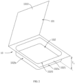
FIG 1 is a schematic structural diagram of a battery cell according to an implementation of this application. -
FIG 2 is an exploded view of a housing of the battery cell illustrated inFIG 1 before packaging. -
FIG 3 is a cross-sectional view of a multi-layer plate material used by a housing of the battery cell illustrated inFIG 1 . -
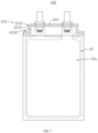
FIG 4 is a schematic structural diagram of the battery cell illustrated inFIG 1 according to some other embodiments. -
FIG 5 is a schematic structural diagram of the battery cell illustrated inFIG 1 according to some other embodiments. -
FIG 6 is part of a cross-sectional view of the battery cell illustrated inFIG 1 in a VI-VI direction. -
FIG 7 is a schematic structural diagram of the battery cell illustrated inFIG 1 according to some other embodiments. -
FIG 8 is a schematic structural diagram of the battery cell illustrated inFIG 1 according to some other embodiments. -
FIG 9 is a schematic structural diagram of the battery cell illustrated inFIG 1 according to some other embodiments. -
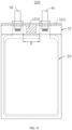
FIG 10 is a schematic structural diagram of a battery cell according to another implementation of this application. -
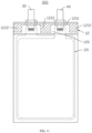
FIG 11 is a schematic structural diagram of a battery cell according to still another implementation of this application. -
FIG 12 is a schematic structural diagram of the battery cell illustrated inFIG 11 according to some other embodiments. -
FIG 13 is a schematic structural diagram of an electric apparatus according to an implementation of this application. -
Electric apparatus 1 Load 2 Housing 10 First side wing 12 Second side wing 13 Electrode assembly 20 Main plane 20a Side 20b First electrode plate 21 Second electrode plate 22 Separator 23 First tab 30 Interior tab 31 Exterior tab 32 Adhesive tape 33 Second tab 40 Cell 100, 200, 300 Cover 101 Cavity 102 First side surface 102a Second side surface 102b Multi-layer plate material 110 Protective layer 111 First binding layer 112 Metal layer 113 Second binding layer 114 Sealing layer 115 Transition portion 120 First connecting portion 121 Unconnected portion 122 Concave structure 123 Protrusion 230 Periphery 1010 Border 1020 Flange 1021 First section 1101 Second section 1102 First transition region 1201 Second transition region 1202 First sealing structure 1211 Second sealing structure 1212 Side wall 1231 Bottom wall 1232 First direction D1 Second direction D2 Thickness direction D3 Thickness T1, T2 Width W1, W2, W3, W4, W5 Distance D - This application will be further described with reference to the accompanying drawings in the following specific embodiments.
- The following clearly and completely describes the technical solutions in the embodiments of this application with reference to the accompanying drawings in the embodiments of this application. Apparently, the described embodiments are only some rather than all of the embodiments of this application.
- Unless otherwise defined, all technical and scientific terms used herein shall have the same meanings as commonly understood by those skilled in the art to which this application belongs. The terms used herein in the specification of this application are merely intended to describe specific embodiments but not intended to limit this application.
- The following describes in detail some embodiments of this application with reference to the accompanying drawings. In absence of conflicts, the following embodiments and features in the embodiments may be combined.
- Referring to
FIG 1 , an implementation of this application provides abattery cell 100, including anelectrode assembly 20, an electrolyte (not shown in the figure), and ahousing 10 for accommodating theelectrode assembly 20 and the electrolyte. Theelectrode assembly 20 includes afirst electrode plate 21 and asecond electrode plate 22 that are arranged alternately, a separator 23 (shown inFIG 6 ) is disposed between thefirst electrode plate 21 and thesecond electrode plate 22 that are adjacent. Theseparator 23 is used to reduce the risk of short circuit caused by direct contact between thefirst electrode plate 21 and thesecond electrode plate 22 that are adjacent. Theelectrode assembly 20 illustrated inFIG 1 is obtained by laminating thefirst electrode plate 21, theseparator 23, and thesecond electrode plate 22. That is, thebattery cell 100 is a battery cell obtained through stacking. In other implementations, thebattery cell 100 may alternatively be a wound battery cell, which is not limited in this application. - Also referring to
FIG 2 , thehousing 10 includes acavity 102 and acover 101 covering thecavity 102. Theelectrode assembly 20 is accommodated in thecavity 102. Aflange 1021 is formed by extending from aborder 1020 of an opening of thecavity 102.Periphery 1010 of thecover 101 is connected to theflange 1021 to form afirst side wing 12. Thefirst side wing 12 is used to seal thecavity 102. Thecavity 102 includes two first side surfaces 102a that are opposite and two second side surfaces 102b that are opposite. The second side surfaces 102b are connected between the twofirst side surfaces 102a. Thefirst side wing 12 is connected to onefirst side surface 102a of thecavity 102. - Also referring to
FIG 3 , in some embodiments, thehousing 10 is made of amulti-layer plate material 110. Themulti-layer plate material 110 may include ametal layer 113 and asealing layer 115 stacked in sequence. Thesealing layer 115 is close to theelectrode assembly 20. Themetal layer 113 is used to prevent water from entering and protect thebattery cell 100 from being damaged by external force. For example, themetal layer 113 may be specifically an aluminum foil layer. Thesealing layer 115 is used for packaging to prevent themulti-layer plate material 110 from being dissolved or swelled by an organic solvent in the electrolyte. Thesealing layer 115 is further used to prevent an electrolyte salt in the electrolyte from coming into contact with themetal layer 113 and corroding themetal layer 113. In some embodiments, themulti-layer plate material 110 may further include aprotective layer 111, a firstbinding layer 112, and a secondbinding layer 114. Theprotective layer 111, the firstbinding layer 112, themetal layer 113, the secondbinding layer 114, and thesealing layer 115 are stacked in sequence. Theprotective layer 111 is made of polymer resin and used to protect themetal layer 113 from being damaged by external force, and can prevent air from entering and maintain a water- and oxygen-free environment inside thebattery cell 100. The firstbinding layer 112 is used to bind theprotective layer 111 and themetal layer 113. The secondbinding layer 114 is used to bind themetal layer 113 and thesealing layer 115. - The
multi-layer plate material 110 includes afirst section 1101 and asecond section 1102. A middle area of afirst section 1101 of themulti-layer plate material 110 depresses to form thecavity 102, and thesecond section 1102 of themulti-layer plate material 110 and thefirst section 1101 are arranged by folding towards each other to form thecover 101. Thecover 101 is used to seal thecavity 102. During preparation of thehousing 10, a heat sealing head can be used to apply specified temperature and pressure on theperiphery 1010 of thecover 101 and theflange 1021 of thecavity 102 for heat sealing. In this way, thesealing layer 115 at theperiphery 1010 of thecover 101 is bound to thesealing layer 115 of theflange 1021 to form thefirst side wing 12, so as to seal thecavity 102 and reduce the risk of electrolyte spill. - As shown in
FIG 1 , thefirst side wing 12 does not need to be folded after heat sealing. That is, thefirst side wing 12 is approximately perpendicular to thefirst side surface 102a. Certainly, this is not limited in this application. In other implementations, thefirst side wing 12 may also be folded onto thefirst side surface 102a to reduce the size of thebattery cell 100 in its length direction, helping increase the space utilization and energy density of thebattery cell 100. - The
battery cell 100 further includes a tab electrically connected to theelectrode assembly 20. The tab is sandwiched between thefirst side wings 12, and extends out of thehousing 10 along thefirst side wing 12 for connection with an external component (not shown in the figure). As shown inFIG 1 , in some embodiments, the tab includes afirst tab 30 and asecond tab 40. Thefirst tab 30 is electrically connected to thefirst electrode plate 21, and thesecond tab 40 is electrically connected to thesecond electrode plate 22. Both thefirst tab 30 and thesecond tab 40 extend out of thehousing 10 along thefirst side wing 12. - As shown in
FIG 1 , thefirst side wing 12 includes afirst sealing structure 1211 and asecond sealing structure 1212 connected to thefirst sealing structure 1211. Both thefirst sealing structure 1211 and thesecond sealing structure 1212 are formed by binding thesealing layer 115 at theperiphery 1010 of thecover 101 to thesealing layer 115 of theflange 1021. A direction from an edge, away from theborder 1020, of thefirst side wing 12 to theborder 1020 is defined as a first direction D1. In a case that thefirst side wing 12 is not folded, the first direction D1 is the length direction of thebattery cell 100. Thesecond sealing structure 1212 exceeds thefirst sealing structure 1211 in the first direction D1. That is, in the first direction D1, width of thefirst sealing structure 1211 is W1 and width of thesecond sealing structure 1212 is W2, and W2>W1. This application requires an improvement only on the structure of the heat sealing head, and does not cause extra burden on the entire process. - In some embodiments, thickness of the battery cell 100 (namely, thickness of the cavity 102) is T1, and T1≥4 mm. That is, the
battery cell 100 is an ultra-thin battery cell. Optionally, T≥2 mm. Theelectrode assembly 20 includes twomain planes 20a disposed opposite each other and aside 20b disposed between the twomain planes 20a. When thebattery cell 100 is a battery cell obtained through stacking, theside 20b is approximately a plane; when thebattery cell 100 is a wound battery cell, theside 20b is a curved face. A plane where the tab is located is parallel to themain plane 20a. In other words, the tab is disposed flat and does not bend inside thehousing 10, so as to avoid an increase in thickness of thebattery cell 100 caused by a bent tab. - In the prior art, if a tab needs to be disposed flat for a thin battery cell, a cavity in the housing for accommodating the electrode assembly needs to be enlarged to hold the tab. However, the tab disposed flat is generally thinner than the electrode assembly, and therefore the cavity tends to collapse under the effect of external force near a location of the tab in the cavity in the case of a thin tab. That easily causes collapse of the cavity in appearance, as well as a slanted tab. Because free space in the housing is larger for the electrode assembly and electrolyte, when the battery cell drops, the moving electrode assembly and electrolyte cause greater impact on sealed edges. As a result, the sealed edges will be broken more easily.
- In this application, the
second sealing structure 1212 is disposed on thefirst side wing 12, without increasing the overall size of thebattery cell 100. In this case, thesecond sealing structure 1212 occupies the space in the cavity previously designed for accommodating the tab, thereby reducing the risk of collapse of the cavity under the effect of external force. In addition, when thebattery cell 100 is mechanically abused (such as drop, collision, and squeezing) and theelectrode assembly 20 moves towards thefirst side wing 12, thesecond sealing structure 1212 can apply resistance to theelectrode assembly 20. This reduces the possibility of theelectrode assembly 20 breaking a seal, reduces the risk of failure of thebattery cell 100, and improves the safety performance of thebattery cell 100. Furthermore, due to disposition of thesecond sealing structure 1212, the sealing width of this portion is increased, and the sealing strength of this portion is improved accordingly, further helping reduce the possibility of theelectrode assembly 20 breaking the seal. - Therefore, when the
battery cell 100 of this application is an ultra-thin battery cell, this application can reduce the occurrence of a problem that the safety performance is degraded because the housing of an ultra-thin battery cell in the prior art tends to collapse due to a larger cavity. Certainly, the technical solution of this application may be further used in athicker battery cell 100, which is not limited in this application. - In some embodiments, W1 and W2 satisfy that 20 mm≤W2-W1≤0.8 mm. W2-W1 represents width of a portion by which the
second sealing structure 1212 exceeds thefirst sealing structure 1211. By means of setting the value of W2-W1, a moving distance of theelectrode assembly 20 is dramatically reduced inside thehousing 10, the sealing strength of thesecond sealing structure 1212 is greatly improved, and the length of thebattery cell 100 is controlled within a range. - Optionally, 3 mm≤W2-W1≤1.7 mm.
- In some other embodiments, W1 and W2 satisfy that (W2-W1)/W2≤17%. According to another embodiment of this application, (W2-W1)/W2≥50%.
- For example, W2 is 4.59 mm and W1 is 1.3 mm. That is, W2-W1=3.29 mm, and (W2-W1)/W2=72%.
- For example, W2 is 4.0 mm and W1 is 2.0 mm. That is, W2-W1=2.00 mm, and (W2-W1)/W2=50%.
- By means of setting the value of (W2-W1)/W2, the moving distance of the
electrode assembly 20 is dramatically reduced inside thehousing 10, and the sealing strength of thesecond sealing structure 1212 is greatly improved. - As shown in
FIG 1 , a direction perpendicular to the first direction D1 is defined as a second direction D2. In some cases, the second direction D2 is a width direction of thebattery cell 100. Thefirst tab 30 and thesecond tab 40 are arranged side by side in the second direction D2. Furthermore, both thefirst tab 30 and thesecond tab 40 include aninterior tab 31 and anexterior tab 32. Theinterior tab 31 is electrically connected to theelectrode assembly 20. To be specific, theinterior tab 31 of thefirst tab 30 is electrically connected to a current collector of thefirst electrode plate 21, and theinterior tab 31 of thesecond tab 40 is electrically connected to a current collector of thesecond electrode plate 22. Theexterior tab 32 is welded to theinterior tab 31 and extends out of thehousing 10 by way of thefirst sealing structure 1211 and/or thesecond sealing structure 1212. Anadhesive tape 33 is disposed at a welding joint of theinterior tab 31 and theexterior tab 32. Theadhesive tape 33 is used to prevent a weld mark at the welding joint from piercing thehousing 10, thereby avoiding risks such as short circuit or electrolyte spill. Thickness of theadhesive tape 33 may be 50-100 µm. - As shown in
FIG 1 , in some embodiments, the tab is sandwiched between thefirst sealing structures 1211. For example, both thefirst tab 30 and thesecond tab 40 are sandwiched between thefirst sealing structures 1211. It should be understood that, in this application, the tab being sandwiched between thefirst sealing structures 1211 means that the tab is sandwiched between thesealing layer 115 at theperiphery 1010 of thecover 101 and thesealing layer 115 of theflange 1021. - Referring to
FIG 4 , in some other embodiments, the tab may also be sandwiched between thesecond sealing structures 1212. For example, both thefirst tab 30 and thesecond tab 40 are sandwiched between thesecond sealing structures 1212. - Referring to
FIG 5 , in another embodiment, thefirst tab 30 is sandwiched between thefirst sealing structures 1211, and thesecond tab 40 is sandwiched between thesecond sealing structures 1212. - As shown in
FIG 1 , in some embodiments, twosecond sealing structures 1212 are provided. Thefirst sealing structure 1211 is disposed between twosecond sealing structures 1212 in the second direction D2. Disposition of twosecond sealing structures 1212 further occupies a space in the cavity previously designed for accommodating the tab. When theelectrode assembly 20 moves towards thefirst side wing 12, thesecond sealing structures 1212 can apply resistance to two positions on an edge of theelectrode assembly 20 facing thefirst side wing 12. Moreover, disposition of thesecond sealing structures 1212 further improves the sealing strength, thereby further reducing the possibility of theelectrode assembly 20 breaking the seal. The twosecond sealing structures 1212 are the same in width W2 in the first direction D1. - In some other embodiments, the two
second sealing structures 1212 are different in width W2 in the first direction D1. - As shown in
FIG 1 , in some embodiments, thefirst tab 30 and one of thesecond sealing structures 1212 are arranged on the same side of thesecond tab 40 in the second direction D2. Thefirst tab 30 and the other one of thesecond sealing structures 1212 are arranged on two sides of thesecond tab 40. - Referring to
FIG 1 andFIG 6 , in some embodiments, atransition portion 120 is disposed between thefirst side wing 12 and thecavity 102. In a thickness direction D3 of thebattery cell 100, thickness T2 of thetransition portion 120 is less than thickness T1 of thecavity 102. At thetransition portion 120, thesealing layer 115 at theperiphery 1010 of thecover 101 is close to but not bound to thesealing layer 115 of theflange 1021. As shown inFIG 1 , in some embodiments, thefirst side wing 12 is further provided with anunconnected portion 122, and both thefirst sealing structure 1211 and thesecond sealing structure 1212 are disposed between theunconnected portion 122 and thetransition portion 120. At theunconnected portion 122, thesealing layer 115 at theperiphery 1010 of thecover 101 adjoins but is not bound to thesealing layer 115 of theflange 1021. Width of theunconnected portion 122 in the first direction D1 is defined as W3, and W3≤0.4 mm. - In some embodiments, the
transition portion 120 is formed by depressing a portion, adjacent to thecavity 102, of themulti-layer plate material 110 for thehousing 10. The depressing direction of this portion is the same as that of thecavity 102, and the depressing depth is less than that of thecavity 102. In this way, thetransition portion 120 provides an accommodating space smaller than thecavity 102, and the accommodating space can be used to accommodate the tabs. - In some embodiments, the
transition portion 120 includes afirst transition region 1201 and asecond transition region 1202 that communicates with thefirst transition region 1201. Thefirst transition region 1201 is connected between thefirst sealing structure 1211 and thecavity 102, and thesecond transition region 1202 is located between thesecond sealing structure 1212 and thecavity 102. Thefirst transition region 1201 is used to accommodate the welding joint of theinterior tab 31 and theexterior tab 32 as well as theadhesive tape 33 disposed at the welding j oint. Also referring toFIG 6 , according to another embodiment of this application, theseparator 23 includes aprotrusion 230 disposed beyond thefirst electrode plate 21. Theprotrusion 230 is disposed on thetransition portion 120 to fill up at least part of space in thetransition portion 120. In this way, a size of a part by which theseparator 23 exceeds thefirst electrode plate 21 and thesecond electrode plate 22 is further increased. This further reduces the risk of a short circuit fire caused by direct contact between thefirst electrode plate 21 and thesecond electrode plate 22 and improves the internal space utilization of thehousing 10. Specifically, theprotrusion 230 of theseparator 23 may be disposed in thefirst transition region 1201. - As shown in
FIG 1 , a distance between an end portion, facing theborder 1020, of thesecond sealing structure 1212 and theborder 1020 is width of thesecond transition region 1202 in the first direction D1. Width of thesecond transition region 1202 is defined as W4, and W4≤0.2 mm. Optionally, W4 is approximately 1 mm. Thesecond transition region 1202 has a specific width, which helps reduce the risk of an adhesive tape on the head portion of theelectrode assembly 20 entering a seal and ensures the sealing reliability. - Referring to
FIG 7 , in some other embodiments, thefirst side wing 12 has aconcave structure 123, and theconcave structure 123 is formed by depressing an edge of thefirst side wing 12 away from the border towards thecavity 102. When thebattery cell 100 is applied to an electric apparatus 1 (shown inFIG 13 ), disposition of theconcave structure 123 allows thebattery cell 100 to adequately fit into the internal space of theelectric apparatus 1. For example, electronic components inside theelectric apparatus 1 can be accommodated in theconcave structure 123. A cross section of theconcave structure 123 may be in the shape of a rectangle or an arc in the direction of themain plane 20a of theelectrode assembly 20, which is not limited in this application. - Two
concave structures 123 are provided. Theconcave structure 123 is arranged on two ends of thefirst side wing 12 in the second direction D2. Thesecond sealing structure 1212 is disposed around theconcave structure 123. As shown inFIG 7 , the cross section of theconcave structure 123 is in the shape of a rectangle in the direction of themain plane 20a of theelectrode assembly 20. Theconcave structure 123 includes aside wall 1231 and abottom wall 1232 connected to theside wall 1231. Thesecond sealing structures 1212 are disposed on theside wall 1231 and thebottom wall 1232 respectively. - Also referring to
FIG 8 , in some other embodiments, thehousing 10 further includes asecond side wing 13. Thesecond side wing 13 is attached to the two second side surfaces 102b of thecavity 102 and used to seal thecavity 102. Thesecond side wing 13 has a third sealing structure (not shown in the figure). The third sealing structure is also formed by binding thesealing layer 115 at theperiphery 1010 of thecover 101 to thesealing layer 115 of theflange 1021. Thesecond sealing structure 1212 is connected to the third sealing structure. - The
second side wing 13 is not folded after heat sealing. That is, thesecond side wing 13 is approximately perpendicular to thesecond side surface 102b. Certainly, this is not limited in this application. In other implementations, thesecond side wing 13 may also be folded onto thesecond side surface 102b to reduce the size of thebattery cell 100 in its width direction, helping increase the space utilization and energy density of thebattery cell 100. - During preparation of the
housing 10, thesecond section 1102 of themulti-layer plate material 110 is folded with regard to thefirst section 1101 to form thecover 101. Thesecond section 1102 and thefirst section 1101 are folded on the otherfirst side surface 102a opposite thefirst side wing 12. That is, thesecond section 1102 and thefirst section 1101 are folded at the tail of theelectrode assembly 20. - Also referring to
FIG 9 , in some other embodiments, thesecond side wing 13 is only connected to onesecond side surface 102b of thecavity 102. During preparation of thehousing 10, thesecond section 1102 and thefirst section 1101 are folded on the othersecond side surface 102b opposite thesecond side wing 13. - Referring to
FIG 10 , another implementation of this application further provides abattery cell 200, which is different from thebattery cell 100 in that only onesecond sealing structure 1212 is provided but twofirst sealing structures 1211 are provided. Thesecond sealing structure 1212 is disposed between twofirst sealing structures 1211. In this way, when theelectrode assembly 20 moves towards thefirst side wing 12, thesecond sealing structure 1212 can apply resistance to a middle position on an edge of theelectrode assembly 20 facing thefirst side wing 12. - In some embodiments, the
second sealing structure 1212 is disposed between thefirst tab 30 and thesecond tab 40. When thesecond sealing structure 1212 is disposed between thefirst tab 30 and thesecond tab 40, a distance D between thefirst tab 30 and thesecond tab 40 needs to satisfy that D>9.64 mm. Therefore, thesecond sealing structure 1212 between thefirst tab 30 and thesecond tab 40 is exposed in a specific size in the second direction D2. In this way, thesecond sealing structure 1212 can effectively reduce the risk of collapse of thecavity 102 under the effect of external force, and he second sealingstructure 1212 can apply great resistance to theelectrode assembly 20 when thebattery cell 100 is mechanically abused. - Referring to
FIG 11 , another implementation of this application further provides abattery cell 300, which is different from thebattery cell 100 in that threesecond sealing structures 1212 are provided. Thefirst tab 30 and one of thesecond sealing structures 1212 are arranged on two sides of thesecond tab 40 in the second direction D2. Thefirst tab 30 and the other two of thesecond sealing structures 1212 are arranged on the same side of thesecond tab 40. - In this way, the three
second sealing structures 1212 occupy the space in the cavity previously designed for accommodating the tab, thereby significantly reducing the risk of collapse of thecavity 102 under the effect of external force. When theelectrode assembly 20 moves towards thefirst side wing 12, thesecond sealing structures 1212 can apply resistance to three positions on an edge of theelectrode assembly 20, improving the sealing strength and further reducing the possibility of theelectrode assembly 20 breaking the seal. - In other embodiments, quantities of
first sealing structures 1211 andsecond sealing structures 1212 can be changed based on actual needs, and a plurality offirst sealing structures 1211 and a plurality ofsecond sealing structures 1212 are disposed alternately. - Also referring to
FIG 12 , in some other embodiments, theconcave structure 123 may also be disposed between thefirst tab 30 and thesecond tab 40. Twosecond sealing structures 1212 are arranged on two sides of theconcave structure 123 in the second direction D2. - The
concave structure 123 is disposed between theunconnected portion 122 and thesecond sealing structure 1212 in the first direction D1. In other words, thesecond sealing structure 1212 is disposed around theconcave structure 123. As shown inFIG 11 , the cross section of theconcave structure 123 is in the shape of a rectangle in the direction of themain plane 20a of theelectrode assembly 20. Theconcave structure 123 includes twoside walls 1231 and thebottom wall 1232 connected between the twoside walls 1231. Thesecond sealing structures 1212 are disposed on each of theside walls 1231 and thebottom wall 1232 respectively. Width of theconcave structure 123 in the first direction D1 is defined as W5, and W5≥3.04 mm. - The
battery cells - Referring to
FIG 13 , an embodiment of this application further provides anelectric apparatus 1, and theelectric apparatus 1 includes a load 2 and the foregoing battery cell 100 (or thebattery cell 200 or 300). Thebattery cell 100 is used to supply power to the load 2. In an embodiment, theelectric apparatus 1 of this application may be, but is not limited to, a notebook computer, a pen-input computer, a mobile computer, an electronic book player, a portable telephone, a portable fax machine, a portable copier, a portable printer, a stereo headset, a video recorder, a liquid crystal television, a portable cleaner, a portable CD player, a mini-disc, a transceiver, an electronic notebook, a calculator, a memory card, a portable recorder, a radio, a standby power source, a motor, an automobile, a motorcycle, a motor bicycle, a bicycle, a lighting appliance, a toy, a game console, a clock, an electric tool, a flash lamp, a camera, a large household battery, a lithium-ion capacitor, or the like. The load 2 is an electronic component of theelectric apparatus 1 electrically connected to thebattery cell 100, and is used to convert electric energy into energy of other forms. - The foregoing descriptions are merely preferable embodiments of this application, but are not intended to limit this application. Any modification, equivalent replacement, or improvement made without departing from the spirit and principle of this application shall fall within the protection scope of this application.
Claims (24)
- A battery cell, comprising an electrode assembly and a housing accommodating the electrode assembly, wherein the housing comprises a cavity and a cover covering the cavity, the cavity comprises a flange extending along a border of an opening of the cavity, and periphery of the cover is connected to the flange to form a side wing to seal the cavity, whereinthe battery cell further comprises tabs sandwiched between the side wings and extending out of the housing along the side wings; andthe side wing has a first sealing structure and a second sealing structure, wherein a direction from an edge, away from the border, of the side wing to the border is defined as a first direction, and the second sealing structure exceeds the first sealing structure in the first direction.
- The battery cell according to claim 1, wherein the tabs is sandwiched between the first sealing structures.
- The battery cell according to claim 1, wherein the tabs are sandwiched between the second sealing structures.
- The battery cell according to claim 1, wherein the tabs comprise a first tab and a second tab, the first tab is sandwiched between the first sealing structure, and the second tab is sandwiched between the second sealing structure.
- The battery cell according to claim 1, wherein the tabs comprise a first tab and a second tab, a direction perpendicular to the first direction is defined as a second direction, and the first tab and the second tab are arranged side by side in the second direction.
- The battery cell according to claim 5, wherein the first sealing structure is disposed between two second sealing structures in the second direction.
- The battery cell according to claim 5, wherein the second sealing structure is disposed between two first sealing structures in the second direction.
- The battery cell according to claim 5, wherein the first tab and the second sealing structure are arranged on two sides of the second tab in the second direction.
- The battery cell according to claim 5, wherein the first tab and the second sealing structure are arranged on the same side of the second tab in the second direction.
- The battery cell according to claim 5, wherein the second sealing structure is disposed between the first tab and the second tab.
- The battery cell according to any one of claims 5 to 10, wherein the side wing has a concave structure, and the concave structure is formed by depressing an edge of the side wing away from the border towards the cavity.
- The battery cell according to claim 11, wherein the concave structure is arranged on two ends of the side wing in the second direction.
- The battery cell according to claim 11, wherein the concave structure is disposed between the first tab and the second tab.
- The battery cell according to claim 11, wherein two second sealing structures are arranged on two sides of the concave structure in the second direction.
- The battery cell according to claim 11, wherein the concave structure is disposed on the second sealing structure in the first direction.
- The battery cell according to claim 1, wherein the housing is made of a multi-layer plate material, the multi-layer plate material comprises a metal layer and a sealing layer, a middle area of a first section of the multi-layer plate material depresses to form the cavity, and a second section of the multi-layer plate material and the first section are arranged by folding towards each other to seal the cavity, wherein the electrode assembly is accommodated in the cavity.
- The battery cell according to claim 16, wherein a sealing layer at the periphery of the cover is bound to a sealing layer of the flange so as to seal the cavity.
- The battery cell according to claim 17, wherein a transition portion is disposed between the side wing and the cavity, a thickness of the transition portion is less than a thickness of the cavity in a thickness direction of the battery cell, and at the transition portion, the sealing layer at the periphery of the cover is close to but not bound to the sealing layer of the flange.
- The battery cell according to claim 18, wherein the electrode assembly comprises a first electrode plate and a second electrode plate that are arranged alternately, a separator is disposed between the first electrode plate and the second electrode plate adjacent to he first electrode plate, the separator comprises a protrusion disposed beyond the first electrode plate, and the protrusion is disposed at the transition portion.
- The battery cell according to claim 1, wherein a thickness of the battery cell is T and T≥4 mm.
- The battery cell according to claim 1, wherein in the first direction, a width of the first sealing structure is W1 and a width of the second sealing structure is W2, and 20 mm≤W2-W1≤0.8 mm.
- The battery cell according to claim 21, wherein 3 mm≤W2-W1≤1.7 mm.
- The battery cell according to claim 21, wherein (W2-W1)/W2≤17%.
- An electric apparatus, comprising a load and the battery cell according to any one of claims 1 to 23, wherein the battery cell is used to supply power to the load.
Applications Claiming Priority (1)
| Application Number | Priority Date | Filing Date | Title |
|---|---|---|---|
| PCT/CN2021/086248 WO2022213379A1 (en) | 2021-04-09 | 2021-04-09 | Battery cell and electrical device |
Publications (2)
| Publication Number | Publication Date |
|---|---|
| EP4307415A1 true EP4307415A1 (en) | 2024-01-17 |
| EP4307415A4 EP4307415A4 (en) | 2024-10-23 |
Family
ID=80659107
Family Applications (1)
| Application Number | Title | Priority Date | Filing Date |
|---|---|---|---|
| EP21935605.2A Pending EP4307415A4 (en) | 2021-04-09 | 2021-04-09 | BATTERY CELL AND ELECTRICAL DEVICE |
Country Status (4)
| Country | Link |
|---|---|
| US (1) | US20240030528A1 (en) |
| EP (1) | EP4307415A4 (en) |
| CN (1) | CN114207931A (en) |
| WO (1) | WO2022213379A1 (en) |
Cited By (1)
| Publication number | Priority date | Publication date | Assignee | Title |
|---|---|---|---|---|
| EP4636912A1 (en) * | 2024-04-16 | 2025-10-22 | Samsung SDI Co., Ltd. | Secondary battery |
Families Citing this family (5)
| Publication number | Priority date | Publication date | Assignee | Title |
|---|---|---|---|---|
| JP2025533549A (en) * | 2022-09-23 | 2025-10-07 | エルジー エナジー ソリューション リミテッド | Pouch-type secondary battery |
| WO2024103325A1 (en) * | 2022-11-17 | 2024-05-23 | 宁德新能源科技有限公司 | Electrochemical apparatus, electronic device, and manufacturing method for electrochemical apparatus |
| CN115498372B (en) * | 2022-11-18 | 2025-05-06 | 宁德新能源科技有限公司 | Electrochemical devices and electronic devices |
| CN116848654A (en) * | 2022-12-26 | 2023-10-03 | 厦门新能安科技有限公司 | Cells, secondary batteries and electrical equipment |
| CN115832541A (en) * | 2022-12-30 | 2023-03-21 | 东莞新能德科技有限公司 | Electrochemical devices and electrical equipment |
Family Cites Families (12)
| Publication number | Priority date | Publication date | Assignee | Title |
|---|---|---|---|---|
| JP4232038B2 (en) * | 2004-08-11 | 2009-03-04 | 日本電気株式会社 | Film-clad electrical device and method for manufacturing the same |
| JP5732687B2 (en) * | 2010-03-19 | 2015-06-10 | エルジー ケム. エルティーディ. | Pouch type case and battery pack including the same |
| KR101200469B1 (en) * | 2010-12-07 | 2012-11-12 | 주식회사 엘지화학 | Secondary battery having differential sealing width |
| KR20140064406A (en) * | 2012-11-20 | 2014-05-28 | 주식회사 엘지화학 | Battery cell having folding grooves |
| KR101547403B1 (en) * | 2013-01-11 | 2015-08-25 | 주식회사 엘지화학 | Secondary battery comprising unified positive lead and negative lead and the method for preparing thereof |
| JP6101726B2 (en) * | 2015-03-25 | 2017-03-22 | オートモーティブエナジーサプライ株式会社 | Lithium ion secondary battery |
| CN107223286A (en) * | 2016-09-14 | 2017-09-29 | 深圳市大疆创新科技有限公司 | Battery and its assemble method, and use the unmanned vehicle of the battery |
| CN206250224U (en) * | 2016-11-18 | 2017-06-13 | 宁德新能源科技有限公司 | Battery core encapsulating structure |
| CN207852828U (en) * | 2018-02-10 | 2018-09-11 | 微宏动力系统(湖州)有限公司 | A kind of soft pack cell |
| CN209496945U (en) * | 2019-01-15 | 2019-10-15 | 东莞新能源科技有限公司 | Battery cell and battery |
| CN113597702B (en) * | 2020-03-24 | 2023-01-24 | 东莞新能安科技有限公司 | Electrochemical device and electronic device |
| CN212725431U (en) * | 2020-07-16 | 2021-03-16 | 湖南立方新能源科技有限责任公司 | A soft-packed cylindrical battery |
-
2021
- 2021-04-09 WO PCT/CN2021/086248 patent/WO2022213379A1/en not_active Ceased
- 2021-04-09 EP EP21935605.2A patent/EP4307415A4/en active Pending
- 2021-04-09 CN CN202180004775.4A patent/CN114207931A/en active Pending
-
2023
- 2023-10-05 US US18/481,302 patent/US20240030528A1/en active Pending
Cited By (1)
| Publication number | Priority date | Publication date | Assignee | Title |
|---|---|---|---|---|
| EP4636912A1 (en) * | 2024-04-16 | 2025-10-22 | Samsung SDI Co., Ltd. | Secondary battery |
Also Published As
| Publication number | Publication date |
|---|---|
| WO2022213379A1 (en) | 2022-10-13 |
| EP4307415A4 (en) | 2024-10-23 |
| US20240030528A1 (en) | 2024-01-25 |
| CN114207931A (en) | 2022-03-18 |
Similar Documents
| Publication | Publication Date | Title |
|---|---|---|
| US20240030528A1 (en) | Cell and electric apparatus | |
| EP4207477A1 (en) | Electrochemical device and electronic device | |
| KR102848263B1 (en) | Secondary batteries, battery modules and devices using batteries as a power source | |
| EP4109617A2 (en) | Electrochemical apparatus and electronic apparatus | |
| KR101006858B1 (en) | Battery pack and manufacturing method thereof | |
| EP2940753B1 (en) | Battery cell having rounded corner | |
| EP1473785B1 (en) | Battery pack and method for producing battery pack | |
| JP7620095B2 (en) | Electrochemical device and its manufacturing method, electronic device | |
| JP3922208B2 (en) | Battery pack and manufacturing method thereof | |
| CN113611986B (en) | Battery cell, battery and electronic equipment | |
| CN113745744A (en) | Solid battery module and solid battery monomer | |
| EP3509124A1 (en) | Insulation plate for secondary battery, secondary battery, and vehicle | |
| KR102512060B1 (en) | Rechargeable battery | |
| EP2916365B1 (en) | Electric device comprising round corner | |
| KR20220142251A (en) | Pouch type battery comprising folded internal electrode lead | |
| KR100731436B1 (en) | Pouch Type Lithium Secondary Battery | |
| US20250149725A1 (en) | Rechargeable battery | |
| CN223285137U (en) | Battery monomer, battery and power consumption device | |
| EP4380324B1 (en) | Printed circuit board, manufacturing method therefor, and battery pack comprising same | |
| US20250149724A1 (en) | Rechargeable battery | |
| KR100670427B1 (en) | Pouch type lithium secondary battery | |
| JP2025149330A (en) | All-solid-state battery and method for manufacturing the same | |
| CN120693725A (en) | Secondary batteries and electronic devices | |
| CN116314836A (en) | secondary battery |
Legal Events
| Date | Code | Title | Description |
|---|---|---|---|
| STAA | Information on the status of an ep patent application or granted ep patent |
Free format text: STATUS: THE INTERNATIONAL PUBLICATION HAS BEEN MADE |
|
| PUAI | Public reference made under article 153(3) epc to a published international application that has entered the european phase |
Free format text: ORIGINAL CODE: 0009012 |
|
| STAA | Information on the status of an ep patent application or granted ep patent |
Free format text: STATUS: REQUEST FOR EXAMINATION WAS MADE |
|
| 17P | Request for examination filed |
Effective date: 20231009 |
|
| AK | Designated contracting states |
Kind code of ref document: A1 Designated state(s): AL AT BE BG CH CY CZ DE DK EE ES FI FR GB GR HR HU IE IS IT LI LT LU LV MC MK MT NL NO PL PT RO RS SE SI SK SM TR |
|
| DAV | Request for validation of the european patent (deleted) | ||
| DAX | Request for extension of the european patent (deleted) | ||
| A4 | Supplementary search report drawn up and despatched |
Effective date: 20240925 |
|
| RIC1 | Information provided on ipc code assigned before grant |
Ipc: H01M 50/242 20210101ALI20240919BHEP Ipc: H01M 50/141 20210101ALI20240919BHEP Ipc: H01M 50/172 20210101ALI20240919BHEP Ipc: H01M 50/186 20210101ALI20240919BHEP Ipc: H01M 50/184 20210101ALI20240919BHEP Ipc: H01M 6/00 20060101ALI20240919BHEP Ipc: H01M 10/04 20060101AFI20240919BHEP |