EP4307403A1 - Impurity detection support device and impurity detection support method - Google Patents
Impurity detection support device and impurity detection support method Download PDFInfo
- Publication number
- EP4307403A1 EP4307403A1 EP21930328.6A EP21930328A EP4307403A1 EP 4307403 A1 EP4307403 A1 EP 4307403A1 EP 21930328 A EP21930328 A EP 21930328A EP 4307403 A1 EP4307403 A1 EP 4307403A1
- Authority
- EP
- European Patent Office
- Prior art keywords
- electrode
- pipe
- under test
- liquid under
- voltage
- Prior art date
- Legal status (The legal status is an assumption and is not a legal conclusion. Google has not performed a legal analysis and makes no representation as to the accuracy of the status listed.)
- Pending
Links
Images

Classifications
-
- G—PHYSICS
- G01—MEASURING; TESTING
- G01N—INVESTIGATING OR ANALYSING MATERIALS BY DETERMINING THEIR CHEMICAL OR PHYSICAL PROPERTIES
- G01N27/00—Investigating or analysing materials by the use of electric, electrochemical, or magnetic means
- G01N27/02—Investigating or analysing materials by the use of electric, electrochemical, or magnetic means by investigating impedance
- G01N27/04—Investigating or analysing materials by the use of electric, electrochemical, or magnetic means by investigating impedance by investigating resistance
- G01N27/06—Investigating or analysing materials by the use of electric, electrochemical, or magnetic means by investigating impedance by investigating resistance of a liquid
- G01N27/07—Construction of measuring vessels; Electrodes therefor
-
- G—PHYSICS
- G01—MEASURING; TESTING
- G01N—INVESTIGATING OR ANALYSING MATERIALS BY DETERMINING THEIR CHEMICAL OR PHYSICAL PROPERTIES
- G01N27/00—Investigating or analysing materials by the use of electric, electrochemical, or magnetic means
- G01N27/02—Investigating or analysing materials by the use of electric, electrochemical, or magnetic means by investigating impedance
- G01N27/04—Investigating or analysing materials by the use of electric, electrochemical, or magnetic means by investigating impedance by investigating resistance
- G01N27/06—Investigating or analysing materials by the use of electric, electrochemical, or magnetic means by investigating impedance by investigating resistance of a liquid
- G01N27/08—Investigating or analysing materials by the use of electric, electrochemical, or magnetic means by investigating impedance by investigating resistance of a liquid which is flowing continuously
-
- G—PHYSICS
- G01—MEASURING; TESTING
- G01N—INVESTIGATING OR ANALYSING MATERIALS BY DETERMINING THEIR CHEMICAL OR PHYSICAL PROPERTIES
- G01N27/00—Investigating or analysing materials by the use of electric, electrochemical, or magnetic means
- G01N27/02—Investigating or analysing materials by the use of electric, electrochemical, or magnetic means by investigating impedance
- G01N27/04—Investigating or analysing materials by the use of electric, electrochemical, or magnetic means by investigating impedance by investigating resistance
- G01N27/20—Investigating the presence of flaws
-
- G—PHYSICS
- G01—MEASURING; TESTING
- G01R—MEASURING ELECTRIC VARIABLES; MEASURING MAGNETIC VARIABLES
- G01R27/00—Arrangements for measuring resistance, reactance, impedance, or electric characteristics derived therefrom
- G01R27/02—Measuring real or complex resistance, reactance, impedance, or other two-pole characteristics derived therefrom, e.g. time constant
- G01R27/22—Measuring resistance of fluids
-
- H—ELECTRICITY
- H01—ELECTRIC ELEMENTS
- H01M—PROCESSES OR MEANS, e.g. BATTERIES, FOR THE DIRECT CONVERSION OF CHEMICAL ENERGY INTO ELECTRICAL ENERGY
- H01M4/00—Electrodes
- H01M4/02—Electrodes composed of, or comprising, active material
- H01M4/04—Processes of manufacture in general
-
- H—ELECTRICITY
- H01—ELECTRIC ELEMENTS
- H01M—PROCESSES OR MEANS, e.g. BATTERIES, FOR THE DIRECT CONVERSION OF CHEMICAL ENERGY INTO ELECTRICAL ENERGY
- H01M4/00—Electrodes
- H01M4/02—Electrodes composed of, or comprising, active material
- H01M4/13—Electrodes for accumulators with non-aqueous electrolyte, e.g. for lithium-accumulators; Processes of manufacture thereof
- H01M4/139—Processes of manufacture
-
- H—ELECTRICITY
- H01—ELECTRIC ELEMENTS
- H01M—PROCESSES OR MEANS, e.g. BATTERIES, FOR THE DIRECT CONVERSION OF CHEMICAL ENERGY INTO ELECTRICAL ENERGY
- H01M4/00—Electrodes
- H01M4/02—Electrodes composed of, or comprising, active material
- H01M4/64—Carriers or collectors
- H01M4/70—Carriers or collectors characterised by shape or form
-
- G—PHYSICS
- G01—MEASURING; TESTING
- G01N—INVESTIGATING OR ANALYSING MATERIALS BY DETERMINING THEIR CHEMICAL OR PHYSICAL PROPERTIES
- G01N27/00—Investigating or analysing materials by the use of electric, electrochemical, or magnetic means
- G01N27/02—Investigating or analysing materials by the use of electric, electrochemical, or magnetic means by investigating impedance
- G01N27/04—Investigating or analysing materials by the use of electric, electrochemical, or magnetic means by investigating impedance by investigating resistance
- G01N27/06—Investigating or analysing materials by the use of electric, electrochemical, or magnetic means by investigating impedance by investigating resistance of a liquid
- G01N27/08—Investigating or analysing materials by the use of electric, electrochemical, or magnetic means by investigating impedance by investigating resistance of a liquid which is flowing continuously
- G01N27/10—Investigation or analysis specially adapted for controlling or monitoring operations or for signalling
-
- G—PHYSICS
- G01—MEASURING; TESTING
- G01N—INVESTIGATING OR ANALYSING MATERIALS BY DETERMINING THEIR CHEMICAL OR PHYSICAL PROPERTIES
- G01N33/00—Investigating or analysing materials by specific methods not covered by groups G01N1/00 - G01N31/00
- G01N33/26—Oils; Viscous liquids; Paints; Inks
- G01N33/32—Paints; Inks
-
- Y—GENERAL TAGGING OF NEW TECHNOLOGICAL DEVELOPMENTS; GENERAL TAGGING OF CROSS-SECTIONAL TECHNOLOGIES SPANNING OVER SEVERAL SECTIONS OF THE IPC; TECHNICAL SUBJECTS COVERED BY FORMER USPC CROSS-REFERENCE ART COLLECTIONS [XRACs] AND DIGESTS
- Y02—TECHNOLOGIES OR APPLICATIONS FOR MITIGATION OR ADAPTATION AGAINST CLIMATE CHANGE
- Y02E—REDUCTION OF GREENHOUSE GAS [GHG] EMISSIONS, RELATED TO ENERGY GENERATION, TRANSMISSION OR DISTRIBUTION
- Y02E60/00—Enabling technologies; Technologies with a potential or indirect contribution to GHG emissions mitigation
- Y02E60/10—Energy storage using batteries
Definitions
- the present disclosure relates to an impurity detection support device and an impurity detection support method.
- conductive particles such as metal particles may be mixed as impurities.
- impurities may cause failure of the electronic device.
- the electronic device include a power storage device such as a lithium ion battery, a lithium ion secondary battery, an alkaline dry battery, an electric double layer capacitor, and an electrochemical capacitor.
- the solid-liquid mixture include an electrode slurry used in these power storage devices. When conductive impurities are mixed in the electrode slurry, the conductive impurities can cause a short circuit between the positive and negative electrodes, etc.
- Patent literature 1 discloses a method for magnetically detecting a metal foreign substance contained in an aqueous slurry containing an electrode active material and a particulate binder.
- the related-art method for detecting conductive impurities by using magnetism has not been able to detect conductive impurities comprised of non-magnetic materials. Therefore, the related-art method has insufficient rate of detection of conductive impurities.
- the present disclosure addresses the issue described above, and a purpose thereof is to provide a technique for increasing the rate of detection of conductive impurities in a liquid under test.
- An aspect of the present disclosure relates to an impurity detection support device.
- the device includes: a pipe in which a liquid under test flows; a first electrode and a second electrode provided in the pipe, the first electrode and the second electrode being arranged such that an AC voltage is adapted to be applied to or an AC current is adapted to be superimposed on the liquid under test in a space extending between a first position of the pipe and a second position shifted from the first position in a direction of extension of the pipe; a power supply unit that applies an AC voltage or superimposes an AC current between the first electrode and the second electrode; a measurement unit that measures a current generated between the first electrode and the second electrode due to application of the AC voltage or measures a voltage generated between the first electrode and the second electrode due to superposition of the AC current; and a calculation unit that calculates a resistance of the liquid under test using a measurement result of the measurement unit, the resistance being an indicator for determining whether or not the liquid under test contains conductive impurities.
- the method includes: causing a liquid under test to flow in a pipe; applying an AC voltage to or superimposing an AC current on the liquid under test in a space extending between a first position of the pipe and a second position shifted from the first position in a direction of extension of the pipe; measuring a current generated due to application of the AC voltage or measuring a voltage generated due to superposition of the AC current; and calculating a resistance of the liquid under test using a measurement result, the resistance being an indicator for determining whether or not the liquid under test contains conductive impurities.
- the rate of detection of conductive impurities in a test liquid under test can be increased.
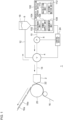
- Fig. 1 is a schematic diagram of a coating device 1 in which an impurity detection support device 100 according to embodiment 1 is provided.
- Fig. 1 depicts some of the constituting elements of the respective devices as functional blocks.
- the functional blocks are implemented in hardware such as devices and circuits exemplified by a CPU and a memory of a computer, and in software such as a computer program. It will be understood by those skilled in the art that these functional blocks are implemented in a variety of manners by a combination of hardware and software.
- the coating device 1 includes a coating die 2, a valve 4, a tank 6, a pump 8, a feed pipe 10, a return pipe 12, and a die supply pipe 14.
- the coating die 2 is an instrument for applying a paint 18 to a coated body 16.
- the coating device 1 of the present embodiment is used, by way of one example, to manufacture an electrode plate of a secondary battery.
- An electrode plate of a secondary battery is a sheet-shaped electrode material obtained by applying an electrode slurry to a current collector and drying the resultant product.
- the coated body 16 is a current collector of a secondary battery
- the paint 18 is an electrode slurry of a secondary battery.
- the current collector is, for example, a metal foil.
- the electrode slurry is an electronically conductive solid-liquid mixture containing a solvent and at least one of an electrode active material or a conductive additive.
- the positive electrode plate is produced by coating an aluminum foil with an electrode slurry containing a positive electrode active material such as lithium cobalt oxide and lithium iron phosphate.
- the slurry for the positive electrode may contain a conductive additive such as graphite.
- the negative electrode plate is produced by coating a copper foil with an electrode slurry containing a negative electrode active material (or conductive additive) such as graphite.
- the coating die 2 is arranged such that a discharge port 22 faces the circumferential surface of a backup roll 20 at a predetermined interval.
- the coated body 16 is continuously transported by the rotation of the backup roll 20 to a position where the backup roll 20 and the discharge port 22 face each other.
- a valve 4 is connected to the coating die 2 via the die supply pipe 14.
- the valve 4 can switch between supply and non-supply of the paint 18 to the coating die 2.
- the coating device 1 can discharge the paint 18 from the coating die 2 to the coated body 16 while the paint 18 is being supplied to the coating die 2.
- the tank 6 is connected to the valve 4 via the feed pipe 10 and the return pipe 12.
- the tank 6 stores the paint 18.
- the feed pipe 10 is provided with the pump 8, and the paint 18 is driven by the pump 8 from the tank 6 to the valve 4.
- the valve 4 supplies the paint 18 supplied from the tank 6 to the coating die 2 via the die supply pipe 14. Alternatively, the valve 4 returns the paint 18 supplied from the tank 6 to the tank 6 via the return pipe 12.
- the paint 18 can be discharged from the coating die 2 to form a coated portion 18a coated with the paint 18 on the coated body 16. Further, as the valve 4 returns the paint 18 to the tank 6, application of the paint 18 from the coating die 2 can be stopped and an uncoated portion 16a not coated with the paint 18 can be formed on the coated body 16. That is, the valve 4 can intermittently coat the paint 18 on the coated body 16. The uncoated portion 16a is used for pasting of the center lead of the electrode.
- the configuration of each part of the coating device 1 is not limited to the one described above.
- the coating device 1 is provided with an impurity detection support device 100 according to the present embodiment.
- the impurity detection support device 100 includes a pipe 102, an electrode unit 104, a power supply unit 106, a measurement unit 108, a calculation unit 110, and a determination unit 112.
- the pipe 102 is a flow path through which the liquid under test that is tested to determine whether or not it contains conductive impurities flows.
- Conductive impurities comprise, for example, a metal.
- the region in the feed pipe 10 between the tank 6 and the pump 8 constitutes the pipe 102. That is, the impurity detection support device 100 is provided in the feed pipe 10. Further, the paint 18, in other words, the electrode slurry, represents the liquid under test.
- the impurity detection support device 100 may be provided in the region in the feed pipe 10 between the pump 8 and the valve 4. Alternatively, the impurity detection support device 100 may be provided in the return pipe 12, the die supply pipe 14, or the like.
- the coating device 1 can also be interpreted as including a circulation device or a transport device for the paint 18 composed of the tank 6, the pump 8, the feed pipe 10, and the return pipe 12. In this case, the impurity detection support device 100 provided in the feed pipe 10 or the return pipe 12 can be interpreted as being provided in the circulation device or the transport device.
- the coating device 1 is not limited to the manufacture of an electrode plate of a secondary battery, and the coated body 16 and the paint 18 may not be an electrode plate and an electrode slurry.
- the impurity detection support device 100 may be provided in a device other than the coating device 1 and, for example, in a manufacturing device for manufacturing the liquid under test.
- the electrode unit 104 includes a first electrode 114 and a second electrode 116.
- the first electrode 114 and the second electrode 116 may be collectively referred to as a pair of electrodes for convenience.
- Figs. 2A-2C are schematic diagrams of the electrode unit 104.
- Fig. 2A shows a first example of the electrode unit 104
- Fig. 2B shows a second example of the electrode unit 104
- Fig. 2C shows a third example of the electrode unit 104.
- illustration of the power supply unit 106 is omitted.
- a pair of electrodes is provided in the pipe 102.
- the electrode unit 104 of the present embodiment has a rod-shaped body 118 that is inserted into the pipe 102 and arranged at an interval from the pipe 102.
- the first electrode 114 is provided in the pipe 102
- the second electrode 116 is provided in the rod-shaped body 118.
- the first electrode 114 and the second electrode 116 are insulated from each other.
- the first electrode 114 and the second electrode 116 are made of a material having electrical conductivity.
- the material has, for example, a volume resistivity of 0.1 ⁇ •cm or less.
- Specific examples of materials constituting the first electrode 114 and the second electrode 116 include insoluble metals such as stainless steel, titanium, platinum, gold, niobium, and ruthenium and include carbon. These materials can also be combined as appropriate.
- the first electrode 114 is provided at least on the inner wall (inner circumferential surface) of the pipe 102.
- the first electrode 114 may be provided on the entire inner wall of the pipe 102 or in a part thereof.
- the first electrode 114 may be provided in a part of the inner wall, it may be provided in a partial region in the direction of flow of the liquid under test, or provided in a partial region in the circumferential direction of the pipe 102.
- the entire pipe 102 may be made of an insoluble metal or the like, and the entire pipe 102 may constitute the first electrode 114. That is, the first electrode 114 may be provided only on the surface of the inner wall of the pipe 102 or may be provided inside the inner wall.
- the second electrode 116 is provided at least on the outer wall (outer circumferential surface) of the rod-shaped body 118.
- the second electrode 116 may be provided on the entire outer wall of the rod-shaped body 118 or may be provided in a part thereof.
- the second electrode 116 may be provided in a part of the outer wall, it may be provided in a partial region in the direction of flow of the liquid under test, or provided in a partial region in the circumferential direction of the rod-shaped body 118.
- the entire rod-shaped body 118 may be made of an insoluble metal or the like, and the entire rod-shaped body 118 may constitute the second electrode 116. That is, the second electrode 116 may be provided only on the surface of the outer wall of the rod-shaped body 118 or may be provided inside the outer wall.
- the first electrode 114 and the second electrode 116 are arranged such that an AC voltage can be applied to or an AC current can be superimposed on the liquid under test in the space extending between an arbitrary first position 102a of the pipe 102 and a second position 102b shifted from the first position 102a in the direction of extension of the pipe 102.
- the first electrode 114 and the second electrode 116 of the present embodiment have an elongated shape extending in the direction of extension of the pipe 102. Therefore, the pair of electrodes extend parallel to the axial center of the pipe 102, spaced apart in the radial direction of the pipe 102.
- the pair of electrodes are arranged such that the distance between the pair of electrodes is equal at any position in the direction of extension of the pipe 102.
- an AC voltage can be applied to or an AC current can be superimposed on the entire liquid under test spreading in the direction of extension of the pipe 102 between the first position 102a and the second position 102b, and, in other words, in the direction of flow of the liquid under test.
- the distance between the first position 102a and the second position 102b, and, in other words, the length of the first electrode 114 and the second electrode 116 in the direction of extension of the pipe 102 is, for example, equal to or greater than the distance between the pair of electrodes, and, in other words, the diameter of the pipe 102, for example.
- the rod-shaped body 118 is arranged such that the distance to the inner wall of the pipe 102 is substantially equal at each position in the direction of extension of the pipe 102. That is, the rod-shaped body 118 extends parallel to the axial center of the pipe 102. Thereby, the distance between the pair of electrodes (the distance in the radial direction of the pipe 102) can be made substantially equal in the direction of extension of the pipe 102. As a result, the accuracy of detection of conductive impurities by the impurity detection support device 100 can be increased. Further, the rod-shaped body 118 is arranged such that the distance to the inner wall of the pipe 102 is substantially equal at each position in the circumferential direction of the rod-shaped body 118.
- the pipe 102 and the rod-shaped body 118 are arranged coaxially. Thereby, the distance between the pair of electrodes can be made substantially equal in the circumferential direction of the rod-shaped body 118. As a result, the accuracy of detection of conductive impurities by the impurity detection support device 100 can be increased. Stated otherwise, the rod-shaped body 118 constituting the second electrode 116 extends, by being inserted into the center of the pipe 102, without being deviated in the radial direction of the pipe 102 and parallel to the direction of extension of the pipe 102 without tilting.
- the rod-shaped body 118 is a hollow body. The interior of the rod-shaped body 118 is sealed and does not allow the liquid under test to flow.
- the rod-shaped body 118 is a solid body. By using a hollow or solid rod-shaped body 118, it is possible to suppress an increase in the pressure loss occurring due to the rod-shaped body 118 when the liquid under test passes through the pipe 102.
- the rod-shaped body 118 is a tubular mesh. The liquid under test can flow in and out of the rod-shaped body 118 through the mesh opening while flowing in the pipe 102. By using the tubular mesh rod-shaped body 118, the contact area between the second electrode 116 and the liquid under test can be increased, and the accuracy of detection of conductive impurities by the impurity detection support device 100 can be increased.
- the power supply unit 106 applies an AC voltage or superimposes an AC current between the first electrode 114 and the second electrode 116.
- the power supply unit 106 can be configured by a known AC/DC converter, inverter, control circuit, or the like.
- the first electrode 114 is connected to the negative electrode output terminal of the power supply unit 106
- the second electrode 116 is connected to the positive electrode output terminal of the power supply unit 106. Therefore, the first electrode 114 is the negative electrode, and the second electrode 116 is the positive electrode.
- the first electrode 114 may be the positive electrode, and the second electrode 116 may be the negative electrode.
- the control circuit is composed of, for example, a microcomputer and can control, according to a measurement result of the measurement unit 108, each switching element of the power supply unit 106 so that the current or the voltage maintains the target value.
- the measurement unit 108 measures the current generated between the first electrode 114 and the second electrode 116 due to the application of the AC voltage. Alternatively, the measurement unit 108 measures the voltage generated between the first electrode 114 and the second electrode 116 due to the superposition of the AC current.
- the measurement unit 108 can be configured by a known ammeter, FRA (Frequency Response Analyzer), or the like electrically connected to the pair of electrodes.
- FRA Frequency Response Analyzer
- the measurement unit 108 can be configured by a known voltmeter, FRA, or the like electrically connected to the pair of electrodes.
- the calculation unit 110 calculates the resistance of the liquid under test by using the measurement result of the measurement unit 108. As an example, the calculation unit 110 calculates the resistance of the liquid under test by the AC impedance method.
- the power supply unit 106 applies the AC voltage between the pair of electrodes, the current generated between the pair of electrodes via the liquid under test is measured by the measurement unit 108.
- the calculation unit 110 can calculate the resistance component of the liquid under test from the value of this current and the value of the AC voltage applied between the pair of electrodes.
- the magnitude of the applied AC voltage can be appropriately selected according to the electrode area, the distance between the electrodes, the type of the liquid under test, and the like, and is preferably 1-100 mV, and, more preferably 5-50 mV.
- the application time of the AC voltage is not particularly limited.
- the AC voltage may be biased.
- the power supply unit 106 superimposes the AC current between the pair of electrodes
- the voltage generated between the pair of electrodes via the liquid under test is measured by the measurement unit 108.
- the calculation unit 110 can calculate the resistance component of the liquid under test from the value of this voltage and the value of the AC current superimposed between the pair of electrodes.
- the magnitude of the AC current superimposed can be appropriately selected according to the electrode area, the distance between the electrodes, the type of the liquid under test, and the like, and is preferably 5 nA-5 A, and, more preferably, 50 nA-500 mA.
- the superposition time of the AC current is not particularly limited.
- the AC current may be biased.
- the AC voltage between the pair of electrodes to calculate the resistance of the liquid under test by the AC impedance method.
- the AC frequency can be appropriately selected according to the electrode area, the distance between the electrodes, the type of the liquid under test, and the like, and is preferably 1 Hz-1000000 Hz, and, more preferably 10000 Hz-1000000 Hz. Thereby, the time required for calculating the resistance can be shortened, and the accuracy of resistance calculation can be further improved.
- the resistance of the liquid under test is reduced regardless of whether the impurities are magnetic or non-magnetic. That is, the resistance of the liquid under test is an indicator for determining whether or not the liquid under test contains conductive impurities. Therefore, it is possible to detect contamination by conductive impurities by capturing the change in resistance of the liquid under test flowing in the pipe 102 by resistance measurement according to the AC impedance method.
- the determination unit 112 determines whether or not the liquid under test contains conductive impurities according to the resistance calculated by the calculation unit 110. For example, the determination unit 112 stores the resistance value of the liquid under test that does not contain conductive impurities in advance as a reference value. The determination unit 112 compares the resistance calculated by the calculation unit 110 with the reference value. When the difference between the calculated resistance and the reference value exceeds a predetermined threshold value, the determination unit 112 determines that the liquid under test contains conductive impurities.
- the threshold value can be appropriately set based on an experiment or simulation by the designer. For example, the threshold value may be zero.
- the determination unit 112 may determine whether or not the liquid under test contains conductive impurities as follows. That is, the electrode unit 104 of the present embodiment generates an electric field in the liquid under test in the space spreading between the first position 102a and the second position 102b. Thereby, the AC voltage can be continuously applied to or the AC current can be continuously superimposed on the liquid under test for a predetermined continuous period of time rather than instantaneously.
- the power supply unit 106 changes the frequency of the AC voltage or the AC current applied to or superimposed on the liquid under test continuously or stepwise.
- the measurement unit 108 measures the current or the voltage generated between the pair of electrodes at a plurality of different frequencies. Thereby, the calculation unit 110 can calculate the resistance of the liquid under test at each frequency.
- the determination unit 112 determines the presence or absence of conductive impurities according to the plurality of resistances calculated by the calculation unit 110. For example, the determination unit 112 determines whether or not the difference of the resistance value at each frequency from the corresponding reference value exceeds a threshold value. Then, the determination unit 112 synthesizes these determination results and determines the presence or absence of conductive impurities. For example, the determination unit 112 determines the presence or absence of conductive impurities according to the number of times that the threshold value is exceeded. Thereby, the accuracy of detection of conductive impurities can be increased.
- the determination unit 112 may also determine the presence or absence of conductive impurities based on the size of an arc in an equivalent circuit model obtained by the AC impedance method. Furthermore, the determination unit 112 may determine the presence or absence of conductive impurities according to the capacitance (electrostatic capacitance) of the liquid under test in addition to the resistance of the liquid under test.
- the determination result of the determination unit 112 is sent to the control device 24.
- the control device 24 may display the determination result of the determination unit 112 on a monitor (not shown). Further, when it is determined by the determination unit 112 that the liquid under test contains conductive impurities, the control device 24 may notify the user of the impurity detection support device 100 of the determination result by a known notification method.
- the notification method is not particularly limited, and a known method such as generating an alert sound or turning on an alert lamp can be employed. Thereby, the user can monitor the presence or absence of conductive impurities in real time. In addition, the user can know contamination by conductive impurities more promptly.
- the value of the voltage or the current measured by the measurement unit 108 may be sent to the control device 24.
- the control device 24 may display a waveform of a voltage value or a current value on an oscilloscope (not shown).
- the value of the resistance calculated by the calculation unit 110 may be sent to the control device 24.
- the control device 24 may display the resistance value on a monitor.
- the resistance value displayed on the monitor may be a plurality of resistance values obtained by changing the frequency of the AC voltage or the AC current. In this case, the user can determine the presence or absence of conductive impurities from the resistance value displayed on the monitor.
- the determination unit 112 may be omitted.
- the execution of the impurity detection process can be directed by the user via the control device 24 or by an operation program in the control device 24. The same applies to a change in the setting of the impurity detection process.
- the control device 24 may control the valve 4 and the pump 8.
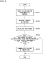
- Fig. 3 is a flowchart showing an example of an impurity detection support method according to embodiment 1. This flow is repeatedly executed at, for example, a predetermined interval.
- an AC voltage is applied or an AC current is superimposed between the first electrode 114 and the second electrode 116 (S101).
- the current generated between the first electrode 114 and the second electrode 116 due to the application of the AC voltage is measured, or the voltage generated between the first electrode 114 and the second electrode 116 due to the superposition of the AC current is measured (S102).
- the resistance of the liquid under test is calculated based on the measured current or voltage (S103). It is then determined whether the difference between the calculated resistance value and the reference value exceeds the threshold value (S104).
- step S104 the determination as to whether or not the difference between one resistance value and the reference value exceeds the threshold value is defined as a determination as to whether or not the liquid under test contains conductive impurities.
- a determination as to whether or not the difference from the reference value exceeds the threshold value may be made for a plurality of resistance values obtained by changing the frequency of the AC voltage or the AC current, and a plurality of determination results may be synthesized to determine whether or not conductive impurities are contained.
- the impurity detection support device 100 includes: a pipe 102 in which a liquid under test flows; a first electrode 114 and a second electrode 116 provided in the pipe 102, the first electrode 114 and the second electrode 116 being arranged such that an AC voltage is adapted to be applied to or an AC current is adapted to be superimposed on the liquid under test in the space extending between a first position 102a in the pipe 102 and a second position 102b shifted from the first position 102a in a direction of extension of the pipe 102, i.e., to the entirety of the liquid under test spread in the space; a power supply unit 106 that applies an AC voltage or superimposes an AC current between the pair of electrodes; a measurement unit 108 that measures a current generated between the pair of electrodes due to application of the AC voltage or measures a voltage generated between the pair of electrodes due to superposition of the AC current; and a calculation unit 110 that calculates a resistance of the liquid under test by using a measurement result
- the impurity detection support device 100 of the present embodiment measures a resistance that serves as an indicator for determining the presence or absence of conductive impurities by applying an AC voltage to or superimposing an AC current on the liquid under test. Therefore, a highly reliable determination indicator can be obtained even if the impurities are non-magnetic. Accordingly, the rate of detection of conductive impurities in the liquid under test can be increased. Further, since an electric field is generated in the liquid under test flowing in the pipe 102, conductive impurities can be detected while the liquid under test is being transported. In other words, an in-line impurity detection process can be realized. In addition, complete inspection of the liquid under test can be easily realized since a work such as sample collection is not required. Therefore, it is possible to suppress introduction of foreign matter into the subsequent process.
- an AC voltage is applied to or an AC current is superimposed on the liquid under test in the space extending between the first position 102a of the pipe 102 and the second position 102b shifted from the first position 102a in the direction of extension of the pipe. This can spread a region where conductive impurities are energized in the direction of flow of the liquid under test and so increase the efficiency of detection of conductive impurities.
- the liquid under test is an electrode slurry containing a solvent and at least one of an electrode active material or a conductive additive.
- the positive electrode slurry contains conductive impurities (particularly, metal impurities) in a power storage device in which an electrolytic solution is interposed between the positive and negative electrodes, conductive impurities could elute in the electrolytic solution when the power storage device is charged, resulting in reduction and precipitation on the surface of the negative electrode.
- the pipe 102 is provided in the coating device 1 including the coating die 2 for applying the liquid under test to the coated body 16 and the tank 6 for storing the liquid under test.
- the pipe 102 is provided in a circulation device or a transport device for the liquid under test.
- the impurity detection process can be performed in the process of transporting the liquid under test from the tank 6 to the coating die 2.
- the impurity detection process can be applied to the liquid under test until just before the liquid under test is applied to the coated body 16, by arranging the impurity detection support device 100 in the feed pipe 10 or the die supply pipe 14 of the coating device 1. Thereby, the risk of foreign matter contamination in the electronic device can be further reduced, and the performance of the electronic device can be further improved.
- the impurity detection support device 100 can be mounted in an existing device simply by using a part of the pipe in the existing device as the pipe 102, or by replacing a part of the pipe by the pipe 102 of the impurity detection support device 100. Therefore, the installation, replacement, and maintenance of the impurity detection support device 100 are easy.
- the impurity detection support device 100 of the present embodiment includes the determination unit 112 that determines whether or not the liquid under test contains conductive impurities according to the resistance calculated by the calculation unit 110. Thereby, the user can know contamination by conductive impurities more promptly.
- the frequency of the AC voltage applied or the AC current superimposed by the power supply unit 106 is changed continuously or stepwise, the measurement unit 108 measures the current or the voltage at different frequencies, the calculation unit 110 calculates a plurality of resistances from the current or the voltage at the respective frequencies, and the determination unit 112 determines whether or not conductive impurities are included according to a plurality of resistances.
- first electrode 114 and the second electrode 116 of the present embodiment have an elongated shape extending in the direction of extension of the pipe 102. Thereby, the area where the electric field is generated can be spread in the direction of extension of the pipe 102 more easily.
- first electrode 114 is provided in the pipe 102
- second electrode 116 is provided in the rod-shaped body 118 inserted into the pipe 102.
- the rod-shaped body 118 is arranged at an interval from the pipe 102. Further, rod-shaped body 118 extends parallel to the axial center of the pipe 102.
- the rod-shaped body 118 is a hollow body, a solid body, or a tubular mesh.
- the rod-shaped body 118 is a hollow body or a solid body, it is possible to suppress an increase in pressure loss occurring when the liquid under test passes through the pipe 102.
- the rod-shaped body 118 is a tubular mesh, the contact area between the second electrode 116 and the liquid under test can be increased to increase the rate of detection of impurities.
- Embodiment 2 has a configuration common to that of the first embodiment except for the shape and arrangement of the first electrode 114 and the second electrode 116.
- the following description of the present embodiment highlights the difference from embodiment 1.
- a description of common features is given only briefly or omitted.
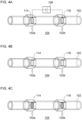
- Figs. 4A-4C are schematic diagrams of the electrode unit 104 provided in the impurity detection support device 100 according to embodiment 2.
- Fig. 4A shows a fourth example of the electrode unit 104
- Fig. 4B is a fifth example of the electrode unit 104
- Fig. 4C shows a sixth example of the electrode unit 104.
- illustration of the power supply unit 106 is omitted.
- the first electrode 114 extends at the first position 102a in a direction intersecting the direction of extension of the pipe 102.
- the second electrode 116 extends at the second position 102b in a direction intersecting the direction of extension of the pipe 102. That is, the pair of electrodes have a filter shape and extend in the radial direction of the pipe 102. Thereby, the region in which conductive impurities are energized can be spread in a direction intersecting the direction of flow of the liquid under test so that the efficiency of detection of conductive impurities can be increased.
- the first electrode 114 and the second electrode 116 are, for example, fixed to the pipe 102.
- insulation is provided between each electrode and the pipe 102.
- insulation between each electrode and the pipe 102 can be omitted, and the electrode and the pipe 102 may be in direct contact with each other.
- the first electrode 114 and the second electrode 116 are mesh sheets.
- the first electrode 114 and the second electrode 116 are slit sheets.
- the first electrode 114 and the second electrode 116 are porous sheets.
- the liquid under test flowing in the pipe 102 can travel downstream from each electrode through the mesh of each electrode.
- the present disclosure can be used in an impurity detection support device and an impurity detection support method.
Landscapes
- Chemical & Material Sciences (AREA)
- Chemical Kinetics & Catalysis (AREA)
- Electrochemistry (AREA)
- General Physics & Mathematics (AREA)
- Physics & Mathematics (AREA)
- Analytical Chemistry (AREA)
- Health & Medical Sciences (AREA)
- Life Sciences & Earth Sciences (AREA)
- Biochemistry (AREA)
- General Health & Medical Sciences (AREA)
- Immunology (AREA)
- Pathology (AREA)
- General Chemical & Material Sciences (AREA)
- Engineering & Computer Science (AREA)
- Manufacturing & Machinery (AREA)
- Materials Engineering (AREA)
- Investigating Or Analyzing Materials By The Use Of Electric Means (AREA)
Abstract
Description
- The present disclosure relates to an impurity detection support device and an impurity detection support method.
- When a solid-liquid mixture having electronic conductivity is produced, conductive particles such as metal particles may be mixed as impurities. In the case a solid-liquid mixture containing conductive impurities is used in an electronic device, impurities may cause failure of the electronic device. Examples of the electronic device include a power storage device such as a lithium ion battery, a lithium ion secondary battery, an alkaline dry battery, an electric double layer capacitor, and an electrochemical capacitor. Examples of the solid-liquid mixture include an electrode slurry used in these power storage devices. When conductive impurities are mixed in the electrode slurry, the conductive impurities can cause a short circuit between the positive and negative electrodes, etc. In this background,
Patent literature 1, for example, discloses a method for magnetically detecting a metal foreign substance contained in an aqueous slurry containing an electrode active material and a particulate binder. - [Patent literature 1]
WO2014/142045 - The related-art method for detecting conductive impurities by using magnetism has not been able to detect conductive impurities comprised of non-magnetic materials. Therefore, the related-art method has insufficient rate of detection of conductive impurities.
- The present disclosure addresses the issue described above, and a purpose thereof is to provide a technique for increasing the rate of detection of conductive impurities in a liquid under test.
- An aspect of the present disclosure relates to an impurity detection support device. The device includes: a pipe in which a liquid under test flows; a first electrode and a second electrode provided in the pipe, the first electrode and the second electrode being arranged such that an AC voltage is adapted to be applied to or an AC current is adapted to be superimposed on the liquid under test in a space extending between a first position of the pipe and a second position shifted from the first position in a direction of extension of the pipe; a power supply unit that applies an AC voltage or superimposes an AC current between the first electrode and the second electrode; a measurement unit that measures a current generated between the first electrode and the second electrode due to application of the AC voltage or measures a voltage generated between the first electrode and the second electrode due to superposition of the AC current; and a calculation unit that calculates a resistance of the liquid under test using a measurement result of the measurement unit, the resistance being an indicator for determining whether or not the liquid under test contains conductive impurities.
- Another aspect of the present disclosure relates to an impurity detection support method. The method includes: causing a liquid under test to flow in a pipe; applying an AC voltage to or superimposing an AC current on the liquid under test in a space extending between a first position of the pipe and a second position shifted from the first position in a direction of extension of the pipe; measuring a current generated due to application of the AC voltage or measuring a voltage generated due to superposition of the AC current; and calculating a resistance of the liquid under test using a measurement result, the resistance being an indicator for determining whether or not the liquid under test contains conductive impurities.
- Optional combinations of the aforementioned constituting elements, and implementations of the disclosure in the form of methods, apparatuses, and systems may also be practiced as additional aspects of the present disclosure.
- According to the present disclosure, the rate of detection of conductive impurities in a test liquid under test can be increased.
-
-
Fig. 1 is a schematic diagram of a coating device in which an impurity detection support device according toembodiment 1 is provided; -
Figs. 2A, 2B and 2C are schematic diagrams of the electrode unit; -
Fig. 3 is a flowchart showing an example of an impurity detection support method according toembodiment 1; and -
Figs. 4A, 4B and 4C are schematic diagrams of the electrode unit provided in the impurity detection support device according toembodiment 2. - Hereinafter, the present disclosure will be described based on preferred embodiments with reference to drawings. The embodiments do not limit the scope of the present disclosure but exemplify the disclosure. Not all of the features and the combinations thereof described in the embodiments are necessarily essential to the present disclosure. Identical or like constituting elements, members, processes shown in the drawings are represented by identical symbols and a duplicate description will be omitted as appropriate. The scales and shapes shown in the figures are defined for convenience's sake to make the explanation easy and shall not be interpreted limitatively unless otherwise specified. Terms like "first", "second", etc. used in the specification and claims do not indicate an order or importance by any means unless otherwise specified and are used to distinguish a certain feature from the others. Those of the members that are not important in describing the embodiment are omitted from the drawings.
-
Fig. 1 is a schematic diagram of acoating device 1 in which an impuritydetection support device 100 according toembodiment 1 is provided.Fig. 1 depicts some of the constituting elements of the respective devices as functional blocks. The functional blocks are implemented in hardware such as devices and circuits exemplified by a CPU and a memory of a computer, and in software such as a computer program. It will be understood by those skilled in the art that these functional blocks are implemented in a variety of manners by a combination of hardware and software. - The
coating device 1 includes acoating die 2, avalve 4, atank 6, apump 8, afeed pipe 10, areturn pipe 12, and adie supply pipe 14. - The coating die 2 is an instrument for applying a
paint 18 to a coatedbody 16. Thecoating device 1 of the present embodiment is used, by way of one example, to manufacture an electrode plate of a secondary battery. An electrode plate of a secondary battery is a sheet-shaped electrode material obtained by applying an electrode slurry to a current collector and drying the resultant product. In the present embodiment, therefore, the coatedbody 16 is a current collector of a secondary battery, and thepaint 18 is an electrode slurry of a secondary battery. The current collector is, for example, a metal foil. The electrode slurry is an electronically conductive solid-liquid mixture containing a solvent and at least one of an electrode active material or a conductive additive. In the case of common lithium ion secondary batteries, the positive electrode plate is produced by coating an aluminum foil with an electrode slurry containing a positive electrode active material such as lithium cobalt oxide and lithium iron phosphate. The slurry for the positive electrode may contain a conductive additive such as graphite. Further, the negative electrode plate is produced by coating a copper foil with an electrode slurry containing a negative electrode active material (or conductive additive) such as graphite. - The
coating die 2 is arranged such that adischarge port 22 faces the circumferential surface of abackup roll 20 at a predetermined interval. The coatedbody 16 is continuously transported by the rotation of thebackup roll 20 to a position where thebackup roll 20 and thedischarge port 22 face each other. - A
valve 4 is connected to the coating die 2 via the diesupply pipe 14. Thevalve 4 can switch between supply and non-supply of thepaint 18 to thecoating die 2. Thecoating device 1 can discharge thepaint 18 from thecoating die 2 to the coatedbody 16 while thepaint 18 is being supplied to thecoating die 2. Thetank 6 is connected to thevalve 4 via thefeed pipe 10 and thereturn pipe 12. - The
tank 6 stores thepaint 18. Thefeed pipe 10 is provided with thepump 8, and thepaint 18 is driven by thepump 8 from thetank 6 to thevalve 4. Thevalve 4 supplies thepaint 18 supplied from thetank 6 to thecoating die 2 via thedie supply pipe 14. Alternatively, thevalve 4 returns thepaint 18 supplied from thetank 6 to thetank 6 via thereturn pipe 12. - As the
valve 4 supplies thepaint 18 to thecoating die 2, thepaint 18 can be discharged from thecoating die 2 to form a coatedportion 18a coated with thepaint 18 on the coatedbody 16. Further, as thevalve 4 returns thepaint 18 to thetank 6, application of thepaint 18 from thecoating die 2 can be stopped and anuncoated portion 16a not coated with thepaint 18 can be formed on the coatedbody 16. That is, thevalve 4 can intermittently coat thepaint 18 on the coatedbody 16. Theuncoated portion 16a is used for pasting of the center lead of the electrode. The configuration of each part of thecoating device 1 is not limited to the one described above. - The
coating device 1 is provided with an impuritydetection support device 100 according to the present embodiment. The impuritydetection support device 100 includes apipe 102, anelectrode unit 104, apower supply unit 106, ameasurement unit 108, acalculation unit 110, and adetermination unit 112. - The
pipe 102 is a flow path through which the liquid under test that is tested to determine whether or not it contains conductive impurities flows. Conductive impurities comprise, for example, a metal. In the present embodiment, the region in thefeed pipe 10 between thetank 6 and thepump 8 constitutes thepipe 102. That is, the impuritydetection support device 100 is provided in thefeed pipe 10. Further, thepaint 18, in other words, the electrode slurry, represents the liquid under test. - The impurity
detection support device 100 may be provided in the region in thefeed pipe 10 between thepump 8 and thevalve 4. Alternatively, the impuritydetection support device 100 may be provided in thereturn pipe 12, thedie supply pipe 14, or the like. Thecoating device 1 can also be interpreted as including a circulation device or a transport device for thepaint 18 composed of thetank 6, thepump 8, thefeed pipe 10, and thereturn pipe 12. In this case, the impuritydetection support device 100 provided in thefeed pipe 10 or thereturn pipe 12 can be interpreted as being provided in the circulation device or the transport device. Further, thecoating device 1 is not limited to the manufacture of an electrode plate of a secondary battery, and thecoated body 16 and thepaint 18 may not be an electrode plate and an electrode slurry. Further, the impuritydetection support device 100 may be provided in a device other than thecoating device 1 and, for example, in a manufacturing device for manufacturing the liquid under test. - The
electrode unit 104 includes afirst electrode 114 and asecond electrode 116. Hereinafter, thefirst electrode 114 and thesecond electrode 116 may be collectively referred to as a pair of electrodes for convenience.Figs. 2A-2C are schematic diagrams of theelectrode unit 104.Fig. 2A shows a first example of theelectrode unit 104,Fig. 2B shows a second example of theelectrode unit 104, andFig. 2C shows a third example of theelectrode unit 104. InFigs. 2B and 2C , illustration of thepower supply unit 106 is omitted. - A pair of electrodes is provided in the
pipe 102. Further, theelectrode unit 104 of the present embodiment has a rod-shapedbody 118 that is inserted into thepipe 102 and arranged at an interval from thepipe 102. Thefirst electrode 114 is provided in thepipe 102, and thesecond electrode 116 is provided in the rod-shapedbody 118. Thefirst electrode 114 and thesecond electrode 116 are insulated from each other. Thefirst electrode 114 and thesecond electrode 116 are made of a material having electrical conductivity. The material has, for example, a volume resistivity of 0.1 Ω•cm or less. Specific examples of materials constituting thefirst electrode 114 and thesecond electrode 116 include insoluble metals such as stainless steel, titanium, platinum, gold, niobium, and ruthenium and include carbon. These materials can also be combined as appropriate. - The
first electrode 114 is provided at least on the inner wall (inner circumferential surface) of thepipe 102. Thefirst electrode 114 may be provided on the entire inner wall of thepipe 102 or in a part thereof. When thefirst electrode 114 is provided in a part of the inner wall, it may be provided in a partial region in the direction of flow of the liquid under test, or provided in a partial region in the circumferential direction of thepipe 102. Further, theentire pipe 102 may be made of an insoluble metal or the like, and theentire pipe 102 may constitute thefirst electrode 114. That is, thefirst electrode 114 may be provided only on the surface of the inner wall of thepipe 102 or may be provided inside the inner wall. - The
second electrode 116 is provided at least on the outer wall (outer circumferential surface) of the rod-shapedbody 118. Thesecond electrode 116 may be provided on the entire outer wall of the rod-shapedbody 118 or may be provided in a part thereof. When thesecond electrode 116 is provided in a part of the outer wall, it may be provided in a partial region in the direction of flow of the liquid under test, or provided in a partial region in the circumferential direction of the rod-shapedbody 118. Further, the entire rod-shapedbody 118 may be made of an insoluble metal or the like, and the entire rod-shapedbody 118 may constitute thesecond electrode 116. That is, thesecond electrode 116 may be provided only on the surface of the outer wall of the rod-shapedbody 118 or may be provided inside the outer wall. - The
first electrode 114 and thesecond electrode 116 are arranged such that an AC voltage can be applied to or an AC current can be superimposed on the liquid under test in the space extending between an arbitraryfirst position 102a of thepipe 102 and asecond position 102b shifted from thefirst position 102a in the direction of extension of thepipe 102. Thefirst electrode 114 and thesecond electrode 116 of the present embodiment have an elongated shape extending in the direction of extension of thepipe 102. Therefore, the pair of electrodes extend parallel to the axial center of thepipe 102, spaced apart in the radial direction of thepipe 102. Preferably, the pair of electrodes are arranged such that the distance between the pair of electrodes is equal at any position in the direction of extension of thepipe 102. - Thereby, an AC voltage can be applied to or an AC current can be superimposed on the entire liquid under test spreading in the direction of extension of the
pipe 102 between thefirst position 102a and thesecond position 102b, and, in other words, in the direction of flow of the liquid under test. The distance between thefirst position 102a and thesecond position 102b, and, in other words, the length of thefirst electrode 114 and thesecond electrode 116 in the direction of extension of thepipe 102 is, for example, equal to or greater than the distance between the pair of electrodes, and, in other words, the diameter of thepipe 102, for example. - Further, the rod-shaped
body 118 is arranged such that the distance to the inner wall of thepipe 102 is substantially equal at each position in the direction of extension of thepipe 102. That is, the rod-shapedbody 118 extends parallel to the axial center of thepipe 102. Thereby, the distance between the pair of electrodes (the distance in the radial direction of the pipe 102) can be made substantially equal in the direction of extension of thepipe 102. As a result, the accuracy of detection of conductive impurities by the impuritydetection support device 100 can be increased. Further, the rod-shapedbody 118 is arranged such that the distance to the inner wall of thepipe 102 is substantially equal at each position in the circumferential direction of the rod-shapedbody 118. That is, thepipe 102 and the rod-shapedbody 118 are arranged coaxially. Thereby, the distance between the pair of electrodes can be made substantially equal in the circumferential direction of the rod-shapedbody 118. As a result, the accuracy of detection of conductive impurities by the impuritydetection support device 100 can be increased. Stated otherwise, the rod-shapedbody 118 constituting thesecond electrode 116 extends, by being inserted into the center of thepipe 102, without being deviated in the radial direction of thepipe 102 and parallel to the direction of extension of thepipe 102 without tilting. - In the first example shown in
Fig. 2A , the rod-shapedbody 118 is a hollow body. The interior of the rod-shapedbody 118 is sealed and does not allow the liquid under test to flow. In the second example shown inFig. 2B , the rod-shapedbody 118 is a solid body. By using a hollow or solid rod-shapedbody 118, it is possible to suppress an increase in the pressure loss occurring due to the rod-shapedbody 118 when the liquid under test passes through thepipe 102. In the third example shown inFig. 2C , on the other hand, the rod-shapedbody 118 is a tubular mesh. The liquid under test can flow in and out of the rod-shapedbody 118 through the mesh opening while flowing in thepipe 102. By using the tubular mesh rod-shapedbody 118, the contact area between thesecond electrode 116 and the liquid under test can be increased, and the accuracy of detection of conductive impurities by the impuritydetection support device 100 can be increased. - The
power supply unit 106 applies an AC voltage or superimposes an AC current between thefirst electrode 114 and thesecond electrode 116. Thepower supply unit 106 can be configured by a known AC/DC converter, inverter, control circuit, or the like. For example, thefirst electrode 114 is connected to the negative electrode output terminal of thepower supply unit 106, and thesecond electrode 116 is connected to the positive electrode output terminal of thepower supply unit 106. Therefore, thefirst electrode 114 is the negative electrode, and thesecond electrode 116 is the positive electrode. Thefirst electrode 114 may be the positive electrode, and thesecond electrode 116 may be the negative electrode. The control circuit is composed of, for example, a microcomputer and can control, according to a measurement result of themeasurement unit 108, each switching element of thepower supply unit 106 so that the current or the voltage maintains the target value. - The
measurement unit 108 measures the current generated between thefirst electrode 114 and thesecond electrode 116 due to the application of the AC voltage. Alternatively, themeasurement unit 108 measures the voltage generated between thefirst electrode 114 and thesecond electrode 116 due to the superposition of the AC current. For measurement of the current generated between the pair of electrodes, themeasurement unit 108 can be configured by a known ammeter, FRA (Frequency Response Analyzer), or the like electrically connected to the pair of electrodes. For measurement of the voltage generated between the pair of electrodes, themeasurement unit 108 can be configured by a known voltmeter, FRA, or the like electrically connected to the pair of electrodes. - The
calculation unit 110 calculates the resistance of the liquid under test by using the measurement result of themeasurement unit 108. As an example, thecalculation unit 110 calculates the resistance of the liquid under test by the AC impedance method. - When the
power supply unit 106 applies the AC voltage between the pair of electrodes, the current generated between the pair of electrodes via the liquid under test is measured by themeasurement unit 108. In this case, thecalculation unit 110 can calculate the resistance component of the liquid under test from the value of this current and the value of the AC voltage applied between the pair of electrodes. The magnitude of the applied AC voltage can be appropriately selected according to the electrode area, the distance between the electrodes, the type of the liquid under test, and the like, and is preferably 1-100 mV, and, more preferably 5-50 mV. The application time of the AC voltage is not particularly limited. The AC voltage may be biased. - Further, when the
power supply unit 106 superimposes the AC current between the pair of electrodes, the voltage generated between the pair of electrodes via the liquid under test is measured by themeasurement unit 108. In this case, thecalculation unit 110 can calculate the resistance component of the liquid under test from the value of this voltage and the value of the AC current superimposed between the pair of electrodes. The magnitude of the AC current superimposed can be appropriately selected according to the electrode area, the distance between the electrodes, the type of the liquid under test, and the like, and is preferably 5 nA-5 A, and, more preferably, 50 nA-500 mA. The superposition time of the AC current is not particularly limited. The AC current may be biased. - In particular, it is preferable to apply the AC voltage between the pair of electrodes to calculate the resistance of the liquid under test by the AC impedance method. The AC frequency can be appropriately selected according to the electrode area, the distance between the electrodes, the type of the liquid under test, and the like, and is preferably 1 Hz-1000000 Hz, and, more preferably 10000 Hz-1000000 Hz. Thereby, the time required for calculating the resistance can be shortened, and the accuracy of resistance calculation can be further improved.
- When conductive impurities such as metals are mixed in the solid-liquid mixture that is the liquid under test, the resistance of the liquid under test is reduced regardless of whether the impurities are magnetic or non-magnetic. That is, the resistance of the liquid under test is an indicator for determining whether or not the liquid under test contains conductive impurities. Therefore, it is possible to detect contamination by conductive impurities by capturing the change in resistance of the liquid under test flowing in the
pipe 102 by resistance measurement according to the AC impedance method. - The
determination unit 112 determines whether or not the liquid under test contains conductive impurities according to the resistance calculated by thecalculation unit 110. For example, thedetermination unit 112 stores the resistance value of the liquid under test that does not contain conductive impurities in advance as a reference value. Thedetermination unit 112 compares the resistance calculated by thecalculation unit 110 with the reference value. When the difference between the calculated resistance and the reference value exceeds a predetermined threshold value, thedetermination unit 112 determines that the liquid under test contains conductive impurities. The threshold value can be appropriately set based on an experiment or simulation by the designer. For example, the threshold value may be zero. - Alternatively, the
determination unit 112 may determine whether or not the liquid under test contains conductive impurities as follows. That is, theelectrode unit 104 of the present embodiment generates an electric field in the liquid under test in the space spreading between thefirst position 102a and thesecond position 102b. Thereby, the AC voltage can be continuously applied to or the AC current can be continuously superimposed on the liquid under test for a predetermined continuous period of time rather than instantaneously. Thepower supply unit 106 changes the frequency of the AC voltage or the AC current applied to or superimposed on the liquid under test continuously or stepwise. Themeasurement unit 108 measures the current or the voltage generated between the pair of electrodes at a plurality of different frequencies. Thereby, thecalculation unit 110 can calculate the resistance of the liquid under test at each frequency. Thedetermination unit 112 determines the presence or absence of conductive impurities according to the plurality of resistances calculated by thecalculation unit 110. For example, thedetermination unit 112 determines whether or not the difference of the resistance value at each frequency from the corresponding reference value exceeds a threshold value. Then, thedetermination unit 112 synthesizes these determination results and determines the presence or absence of conductive impurities. For example, thedetermination unit 112 determines the presence or absence of conductive impurities according to the number of times that the threshold value is exceeded. Thereby, the accuracy of detection of conductive impurities can be increased. - The
determination unit 112 may also determine the presence or absence of conductive impurities based on the size of an arc in an equivalent circuit model obtained by the AC impedance method. Furthermore, thedetermination unit 112 may determine the presence or absence of conductive impurities according to the capacitance (electrostatic capacitance) of the liquid under test in addition to the resistance of the liquid under test. - As an example, the determination result of the
determination unit 112 is sent to thecontrol device 24. Thecontrol device 24 may display the determination result of thedetermination unit 112 on a monitor (not shown). Further, when it is determined by thedetermination unit 112 that the liquid under test contains conductive impurities, thecontrol device 24 may notify the user of the impuritydetection support device 100 of the determination result by a known notification method. The notification method is not particularly limited, and a known method such as generating an alert sound or turning on an alert lamp can be employed. Thereby, the user can monitor the presence or absence of conductive impurities in real time. In addition, the user can know contamination by conductive impurities more promptly. - Further, the value of the voltage or the current measured by the
measurement unit 108 may be sent to thecontrol device 24. Thecontrol device 24 may display a waveform of a voltage value or a current value on an oscilloscope (not shown). Further, the value of the resistance calculated by thecalculation unit 110 may be sent to thecontrol device 24. Thecontrol device 24 may display the resistance value on a monitor. The resistance value displayed on the monitor may be a plurality of resistance values obtained by changing the frequency of the AC voltage or the AC current. In this case, the user can determine the presence or absence of conductive impurities from the resistance value displayed on the monitor. When the resistance value itself is used by the user, thedetermination unit 112 may be omitted. - As an example, the execution of the impurity detection process can be directed by the user via the
control device 24 or by an operation program in thecontrol device 24. The same applies to a change in the setting of the impurity detection process. Further, thecontrol device 24 may control thevalve 4 and thepump 8. -
Fig. 3 is a flowchart showing an example of an impurity detection support method according toembodiment 1. This flow is repeatedly executed at, for example, a predetermined interval. - First, an AC voltage is applied or an AC current is superimposed between the
first electrode 114 and the second electrode 116 (S101). Next, the current generated between thefirst electrode 114 and thesecond electrode 116 due to the application of the AC voltage is measured, or the voltage generated between thefirst electrode 114 and thesecond electrode 116 due to the superposition of the AC current is measured (S102). Subsequently, the resistance of the liquid under test is calculated based on the measured current or voltage (S103). It is then determined whether the difference between the calculated resistance value and the reference value exceeds the threshold value (S104). - When the difference between the resistance value and the reference value exceeds the threshold value (Y of S104), the user is notified that the liquid under test contains impurities (S105), and the routine ends. When the difference between the resistance value and the reference value is equal to or less than the threshold value (N in S104), the user is not notified, and the routine ends. In step S104, the determination as to whether or not the difference between one resistance value and the reference value exceeds the threshold value is defined as a determination as to whether or not the liquid under test contains conductive impurities. Alternatively, a determination as to whether or not the difference from the reference value exceeds the threshold value may be made for a plurality of resistance values obtained by changing the frequency of the AC voltage or the AC current, and a plurality of determination results may be synthesized to determine whether or not conductive impurities are contained.
- As described above, the impurity
detection support device 100 according to the embodiment includes: apipe 102 in which a liquid under test flows; afirst electrode 114 and asecond electrode 116 provided in thepipe 102, thefirst electrode 114 and thesecond electrode 116 being arranged such that an AC voltage is adapted to be applied to or an AC current is adapted to be superimposed on the liquid under test in the space extending between afirst position 102a in thepipe 102 and asecond position 102b shifted from thefirst position 102a in a direction of extension of thepipe 102, i.e., to the entirety of the liquid under test spread in the space; apower supply unit 106 that applies an AC voltage or superimposes an AC current between the pair of electrodes; ameasurement unit 108 that measures a current generated between the pair of electrodes due to application of the AC voltage or measures a voltage generated between the pair of electrodes due to superposition of the AC current; and acalculation unit 110 that calculates a resistance of the liquid under test by using a measurement result of themeasurement unit 108, the resistance being an indicator for determining whether or not the liquid under test contains conductive impurities. - The impurity
detection support device 100 of the present embodiment measures a resistance that serves as an indicator for determining the presence or absence of conductive impurities by applying an AC voltage to or superimposing an AC current on the liquid under test. Therefore, a highly reliable determination indicator can be obtained even if the impurities are non-magnetic. Accordingly, the rate of detection of conductive impurities in the liquid under test can be increased. Further, since an electric field is generated in the liquid under test flowing in thepipe 102, conductive impurities can be detected while the liquid under test is being transported. In other words, an in-line impurity detection process can be realized. In addition, complete inspection of the liquid under test can be easily realized since a work such as sample collection is not required. Therefore, it is possible to suppress introduction of foreign matter into the subsequent process. - Further, an AC voltage is applied to or an AC current is superimposed on the liquid under test in the space extending between the
first position 102a of thepipe 102 and thesecond position 102b shifted from thefirst position 102a in the direction of extension of the pipe. This can spread a region where conductive impurities are energized in the direction of flow of the liquid under test and so increase the efficiency of detection of conductive impurities. - By way of example, the liquid under test is an electrode slurry containing a solvent and at least one of an electrode active material or a conductive additive. In this case, it is possible to suppress a short circuit between the positive and negative electrodes caused by conductive impurities themselves by detecting conductive impurities with high accuracy. If the positive electrode slurry contains conductive impurities (particularly, metal impurities) in a power storage device in which an electrolytic solution is interposed between the positive and negative electrodes, conductive impurities could elute in the electrolytic solution when the power storage device is charged, resulting in reduction and precipitation on the surface of the negative electrode. When this precipitation is repeated, conductive impurities could grow in a dendrite shape, penetrate the separator, and reach the positive electrode, causing a short circuit. Therefore, it is also possible to suppress a short circuit caused by a dendrite, by increasing the rate of detection of conductive impurities.
- As an example, the
pipe 102 is provided in thecoating device 1 including the coating die 2 for applying the liquid under test to thecoated body 16 and thetank 6 for storing the liquid under test. Alternatively, thepipe 102 is provided in a circulation device or a transport device for the liquid under test. Thereby, the impurity detection process can be performed in the process of transporting the liquid under test from thetank 6 to the coating die 2. Further, the impurity detection process can be applied to the liquid under test until just before the liquid under test is applied to thecoated body 16, by arranging the impuritydetection support device 100 in thefeed pipe 10 or thedie supply pipe 14 of thecoating device 1. Thereby, the risk of foreign matter contamination in the electronic device can be further reduced, and the performance of the electronic device can be further improved. - Further, the impurity
detection support device 100 can be mounted in an existing device simply by using a part of the pipe in the existing device as thepipe 102, or by replacing a part of the pipe by thepipe 102 of the impuritydetection support device 100. Therefore, the installation, replacement, and maintenance of the impuritydetection support device 100 are easy. - Further, the impurity
detection support device 100 of the present embodiment includes thedetermination unit 112 that determines whether or not the liquid under test contains conductive impurities according to the resistance calculated by thecalculation unit 110. Thereby, the user can know contamination by conductive impurities more promptly. - Further, as an example of determining whether or not conductive impurities are included, the frequency of the AC voltage applied or the AC current superimposed by the
power supply unit 106 is changed continuously or stepwise, themeasurement unit 108 measures the current or the voltage at different frequencies, thecalculation unit 110 calculates a plurality of resistances from the current or the voltage at the respective frequencies, and thedetermination unit 112 determines whether or not conductive impurities are included according to a plurality of resistances. Thereby, the accuracy of detection of conductive impurities can be further improved. - Further, the
first electrode 114 and thesecond electrode 116 of the present embodiment have an elongated shape extending in the direction of extension of thepipe 102. Thereby, the area where the electric field is generated can be spread in the direction of extension of thepipe 102 more easily. Further, thefirst electrode 114 is provided in thepipe 102, and thesecond electrode 116 is provided in the rod-shapedbody 118 inserted into thepipe 102. The rod-shapedbody 118 is arranged at an interval from thepipe 102. Further, rod-shapedbody 118 extends parallel to the axial center of thepipe 102. Thereby, it can be made easy to keep the distance between the pairs of electrodes uniform in all regions and generate an electric field more uniformly in all regions, even when the region in which the electric field is generated is spread in the direction of extension of thepipe 102. Further, the rod-shapedbody 118 is a hollow body, a solid body, or a tubular mesh. When the rod-shapedbody 118 is a hollow body or a solid body, it is possible to suppress an increase in pressure loss occurring when the liquid under test passes through thepipe 102. When the rod-shapedbody 118 is a tubular mesh, the contact area between thesecond electrode 116 and the liquid under test can be increased to increase the rate of detection of impurities. -
Embodiment 2 has a configuration common to that of the first embodiment except for the shape and arrangement of thefirst electrode 114 and thesecond electrode 116. The following description of the present embodiment highlights the difference fromembodiment 1. A description of common features is given only briefly or omitted. -
Figs. 4A-4C are schematic diagrams of theelectrode unit 104 provided in the impuritydetection support device 100 according toembodiment 2.Fig. 4A shows a fourth example of theelectrode unit 104,Fig. 4B is a fifth example of theelectrode unit 104, andFig. 4C shows a sixth example of theelectrode unit 104. InFigs. 4B and 4C , illustration of thepower supply unit 106 is omitted. - In the present embodiment, the
first electrode 114 extends at thefirst position 102a in a direction intersecting the direction of extension of thepipe 102. Further, thesecond electrode 116 extends at thesecond position 102b in a direction intersecting the direction of extension of thepipe 102. That is, the pair of electrodes have a filter shape and extend in the radial direction of thepipe 102. Thereby, the region in which conductive impurities are energized can be spread in a direction intersecting the direction of flow of the liquid under test so that the efficiency of detection of conductive impurities can be increased. - The
first electrode 114 and thesecond electrode 116 are, for example, fixed to thepipe 102. When thepipe 102 is made of a metal, insulation is provided between each electrode and thepipe 102. When thepipe 102 is non-metallic, insulation between each electrode and thepipe 102 can be omitted, and the electrode and thepipe 102 may be in direct contact with each other. - In the fourth example shown in
Fig. 4A , thefirst electrode 114 and thesecond electrode 116 are mesh sheets. In the fifth example shown inFig. 4B , thefirst electrode 114 and thesecond electrode 116 are slit sheets. In the sixth example shown inFig. 4C , thefirst electrode 114 and thesecond electrode 116 are porous sheets. The liquid under test flowing in thepipe 102 can travel downstream from each electrode through the mesh of each electrode. By configuring each electrode to have a filter shape, the contact area between each electrode and the liquid under test can be increased, and the accuracy of detection of conductive impurities by the impuritydetection support device 100 can be increased. - The embodiments of the present disclosure are described above in detail. The embodiments described above are merely specific examples of practicing the present disclosure. The details of the embodiments shall not be construed as limiting the technical scope of the present disclosure. A number of design modifications such as modification, addition, deletion, etc. of constituting elements may be made to the extent that they do not depart from the idea of the present disclosure defined by the claims. New embodiments with design modifications will provide the combined advantages of the embodiment and the variation. Although the details subject to such design modification are emphasized in the embodiment described above by using phrases such as "of this embodiment" and "in this embodiment", details not referred to as such are also subject to design modification. Any combination of the above constituting elements is also useful as a mode of the present disclosure. Hatching in the cross section in the drawings should not be construed as limiting the material of the hatched object.
- The inventions according to the embodiments described above may be defined by the following items.
- [Item 1] An impurity detection support device (100) including:
- a pipe (102) in which a liquid under test flows;
- a first electrode (114) and a second electrode (116) provided in the pipe (102), the first electrode (114) and the second electrode (116) being arranged such that an AC voltage is adapted to be applied to or an AC current is adapted to be superimposed on the liquid under test in a space extending between a first position (102a) of the pipe (102) and a second position (102b) shifted from the first position (102a) in a direction of extension of the pipe (102);
- a power supply unit (106) that applies an AC voltage or superimposes an AC current between the first electrode (114) and the second electrode (116);
- a measurement unit (108) that measures a current generated between the first electrode (114) and the second electrode (116) due to application of the AC voltage or measures a voltage generated between the first electrode (114) and the second electrode (116) due to superposition of the AC current; and
- a calculation unit (110) that calculates a resistance of the liquid under test using a measurement result of the measurement unit (108), the resistance being an indicator for determining whether or not the liquid under test contains conductive impurities.
- [Item 2] The impurity detection support device (100) according to
item 1, including: a determination unit (112) that determines whether or not the liquid under test contains conductive impurities according to the resistance calculated by the calculation unit (110). - [Item 3] The impurity detection support device (100) according to
item 2, wherein- the power supply unit (106) changes a frequency of a voltage applied or a current superimposed continuously or stepwise,
- the measurement unit (108) measures a current or a voltage at different frequencies,
- the calculation unit (110) calculates a plurality of resistances from currents or voltages at respective frequencies, and
- the determination unit (112) determines whether or not conductive impurities are contained according to the plurality of resistances.
- [Item 4] The impurity detection support device (100) according to any one of
items 1 through 3, wherein
the first electrode (114) and the second electrode (116) have an elongated shape extending in the direction of extension. - [Item 5] The impurity detection support device (100) according to
item 4, wherein- the first electrode (114) is provided in the pipe (102), and
- the second electrode (116) is provided in a rod-shaped body (118) that is inserted into the pipe (102) and arranged at an interval from the pipe (102).
- [Item 6] The impurity detection support device according to item 5, wherein
the rod-shaped body (118) extends parallel to an axial center of the pipe (102). - [Item 7] The impurity detection support device (100) according to
item 5 or 6, wherein
the rod-shaped body (118) is a hollow body, a solid body, or a tubular mesh. - [Item 8] The impurity detection support device (100) according to any one of
items 1 through 3, wherein- the first electrode (114) extends at the first position (102a) in a direction intersecting the direction of extension, and
- the second electrode (116) extends at the second position (102b) in a direction intersecting the direction of extension.
- [Item 9] The impurity detection support device (100) according to
item 8, wherein
the first electrode (114) and the second electrode (116) are mesh sheets, slit sheets, or porous sheets. - [Item 10] The impurity detection support device (100) according to any one of
items 1 through 9, wherein
the liquid under test is an electrode slurry containing a solvent and at least one of an electrode active material or a conductive additive. - [Item 11] The impurity detection support device (100) according to any one of
items 1 through 10, wherein
the pipe (102) is provided in at least one of a coating device (1) that coats a coated body (16) with the liquid under test, a circulation device for the liquid under test, or a transport device for the liquid under test. - [Item 12] An impurity detection support method comprising:
- causing a liquid under test to flow in a pipe (102);
- applying an AC voltage to or superimposing an AC current on the liquid under test in a space extending between a first position (102a) of the pipe (102) and a second position (102b) shifted from the first position (102a) in a direction of extension of the pipe (102);
- measuring a current generated due to application of the AC voltage or measuring a voltage generated due to superposition of the AC current; and
- calculating a resistance of the liquid under test using a measurement result, the resistance being an indicator for determining whether or not the liquid under test contains conductive impurities.
- [Item 13] The impurity detection support method according to
item 12, including:
determining whether or not the liquid under test contains conductive impurities according to the resistance calculated. - [Item 14] The impurity detection support method according to item 13, wherein
- in the applying of the AC voltage or superimposing the AC current, a frequency of the AC voltage or the AC current is changed continuously or in steps,
- in the measuring, a current or a voltage is measured at different frequencies,
- in the calculating, a plurality of resistances are calculated from currents or voltages at respective frequencies, and
- in the determining, it is determined whether or not conductive impurities are contained according to the plurality of resistances.
- The present disclosure can be used in an impurity detection support device and an impurity detection support method.
- 1 coating device, 2 coating die, 6 tank, 16 coated body, 100 impurity detection support device, 102 pipe, 102a first position, 102b second position, 106 power supply unit, 108 measurement unit, 110 calculation unit, 112 determination unit, 114 first electrode, 116 second electrode, 118 rod-shaped body
Claims (14)
- An impurity detection support device comprising:
a pipe in which a liquid under test flows;a first electrode and a second electrode provided in the pipe, the first electrode and the second electrode being arranged such that an AC voltage is adapted to be applied to or an AC current is adapted to be superimposed on the liquid under test in a space extending between a first position of the pipe and a second position shifted from the first position in a direction of extension of the pipe;a power supply unit that applies an AC voltage or superimposes an AC current between the first electrode and the second electrode;a measurement unit that measures a current generated between the first electrode and the second electrode due to application of the AC voltage or measures a voltage generated between the first electrode and the second electrode due to superposition of the AC current; anda calculation unit that calculates a resistance of the liquid under test using a measurement result of the measurement unit, the resistance being an indicator for determining whether or not the liquid under test contains conductive impurities. - The impurity detection support device according to claim 1, comprising:
a determination unit that determines whether or not the liquid under test contains conductive impurities according to the resistance calculated by the calculation unit. - The impurity detection support device according to claim 2, whereinthe power supply unit changes a frequency of the AC voltage applied or the AC current superimposed continuously or in steps,the measurement unit measures a current or a voltage at different frequencies,the calculation unit calculates a plurality of resistances from currents or voltages at respective frequencies, andthe determination unit determines whether or not conductive impurities are contained according to the plurality of resistances.
- The impurity detection support device according to any one of claims 1 through 3, wherein
the first electrode and the second electrode have an elongated shape extending in the direction of extension. - The impurity detection support device according to claim 4, whereinthe first electrode is provided in the pipe, andthe second electrode is provided in a rod-shaped body that is inserted into the pipe and arranged at an interval from the pipe.
- The impurity detection support device according to claim 5, wherein
the rod-shaped body extends parallel to an axial center of the pipe. - The impurity detection support device according to claim 5 or 6, wherein
the rod-shaped body is a hollow body, a solid body, or a tubular mesh. - The impurity detection support device according to any one of claims 1 through 3, whereinthe first electrode extends at the first position in a direction intersecting the direction of extension, andthe second electrode extends at the second position in a direction intersecting the direction of extension.
- The impurity detection support device according to claim 8, wherein
the first electrode and the second electrode are mesh sheets, slit sheets, or porous sheets. - The impurity detection support device according to any one of claims 1 through 9, wherein
the liquid under test is an electrode slurry containing a solvent and at least one of an electrode active material or a conductive additive. - The impurity detection support device according to any one of claims 1 through 10, wherein
the pipe is provided in at least one of a coating device that coats a coated body with the liquid under test, a circulation device for the liquid under test, or a transport device for the liquid under test. - An impurity detection support method comprising:causing a liquid under test to flow in a pipe;applying an AC voltage to or superimposing an AC current on the liquid under test in a space extending between a first position of the pipe and a second position shifted from the first position in a direction of extension of the pipe;measuring a current generated due to application of the AC voltage or measuring a voltage generated due to superposition of the AC current; andcalculating a resistance of the liquid under test using a measurement result, the resistance being an indicator for determining whether or not the liquid under test contains conductive impurities.
- The impurity detection support method according to claim 12, comprising:
determining whether or not the liquid under test contains conductive impurities according to the resistance calculated. - The impurity detection support method according to claim 13, whereinin the applying of the AC voltage or superimposing the AC current, a frequency of the AC voltage or the AC current is changed continuously or in steps,in the measuring, a current or a voltage is measured at different frequencies,in the calculating, a plurality of resistances are calculated from currents or voltages at respective frequencies, andin the determining, it is determined whether or not conductive impurities are contained according to the plurality of resistances.
Applications Claiming Priority (2)
| Application Number | Priority Date | Filing Date | Title |
|---|---|---|---|
| JP2021039315 | 2021-03-11 | ||
| PCT/JP2021/044045 WO2022190482A1 (en) | 2021-03-11 | 2021-12-01 | Impurity detection support device and impurity detection support method |
Publications (2)
| Publication Number | Publication Date |
|---|---|
| EP4307403A1 true EP4307403A1 (en) | 2024-01-17 |
| EP4307403A4 EP4307403A4 (en) | 2024-07-31 |
Family
ID=83226049
Family Applications (1)
| Application Number | Title | Priority Date | Filing Date |
|---|---|---|---|
| EP21930328.6A Pending EP4307403A4 (en) | 2021-03-11 | 2021-12-01 | DEVICE FOR ASSISTANCE IN THE DETECTION OF CONTAMINATIONS AND METHOD FOR ASSISTANCE IN THE DETECTION OF CONTAMINATIONS |
Country Status (5)
| Country | Link |
|---|---|
| US (1) | US12546735B2 (en) |
| EP (1) | EP4307403A4 (en) |
| JP (1) | JP7813989B2 (en) |
| CN (1) | CN117015703A (en) |
| WO (1) | WO2022190482A1 (en) |
Families Citing this family (3)
| Publication number | Priority date | Publication date | Assignee | Title |
|---|---|---|---|---|
| TWI848510B (en) * | 2023-01-09 | 2024-07-11 | 力晶積成電子製造股份有限公司 | Pipeline detection device and pipeline detection system |
| AT528341A1 (en) * | 2024-06-05 | 2025-12-15 | John Deere Electric Powertrain Llc | Device for measuring impurities in a flow channel |
| WO2025263296A1 (en) * | 2024-06-20 | 2025-12-26 | パナソニックIpマネジメント株式会社 | Dispersion processing system and dispersion processing method |
Family Cites Families (10)
| Publication number | Priority date | Publication date | Assignee | Title |
|---|---|---|---|---|
| GB9901572D0 (en) * | 1999-01-26 | 1999-03-17 | Integriti Investments Limited | Corrosion detection under lagging |
| NL1016633C2 (en) | 2000-11-17 | 2002-05-22 | Martil Instr B V | Method and device for determining at least one property of a biological fluid. |
| AUPR692201A0 (en) | 2001-08-09 | 2001-08-30 | Commonwealth Scientific And Industrial Research Organisation | Online fluid contaminant detector |
| WO2011017300A2 (en) | 2009-08-03 | 2011-02-10 | Microfier, Inc. | Method and apparatus for the purification and analytical evaluation of highly purified liquids |
| WO2014142045A1 (en) | 2013-03-14 | 2014-09-18 | 日本ゼオン株式会社 | Method for manufacturing composite particles for electrochemical element electrode |
| JP6173462B2 (en) | 2013-08-07 | 2017-08-02 | 三菱電機株式会社 | Anti-corrosion performance deterioration detection device, hot-water supply heating system and equipment |
| JP2015222651A (en) | 2014-05-22 | 2015-12-10 | トヨタ自動車株式会社 | Manufacturing method of paste |
| KR20180101086A (en) * | 2017-03-03 | 2018-09-12 | 김태용 | Device for measuring water quality |
| DE102018108601A1 (en) | 2018-04-11 | 2019-10-17 | saturn petcare gmbh | Device for detecting foreign bodies in a substrate stream |
| CN109115838B (en) | 2018-08-29 | 2021-04-23 | 大连海事大学 | A multi-parameter oil detection device and its manufacturing method |
-
2021
- 2021-12-01 US US18/281,249 patent/US12546735B2/en active Active
- 2021-12-01 JP JP2023505106A patent/JP7813989B2/en active Active
- 2021-12-01 WO PCT/JP2021/044045 patent/WO2022190482A1/en not_active Ceased
- 2021-12-01 EP EP21930328.6A patent/EP4307403A4/en active Pending
- 2021-12-01 CN CN202180095177.2A patent/CN117015703A/en active Pending
Also Published As
| Publication number | Publication date |
|---|---|
| JP7813989B2 (en) | 2026-02-16 |
| US20240151672A1 (en) | 2024-05-09 |
| US12546735B2 (en) | 2026-02-10 |
| EP4307403A4 (en) | 2024-07-31 |
| JPWO2022190482A1 (en) | 2022-09-15 |
| WO2022190482A1 (en) | 2022-09-15 |
| CN117015703A (en) | 2023-11-07 |
Similar Documents
| Publication | Publication Date | Title |
|---|---|---|
| US12546735B2 (en) | Impurity detection support device and impurity detection support method | |
| EP4563992A1 (en) | Impurity detection support device, impurity detection support method, and test liquid processing system | |
| EP2997389B1 (en) | Estimation of the state of charge of a positive electrolyte solution of a working redox flow battery cell without using any reference electrode | |
| Blanke et al. | Impedance measurements on lead–acid batteries for state-of-charge, state-of-health and cranking capability prognosis in electric and hybrid electric vehicles | |
| Tobias et al. | The immersion potential of high surface electrodes | |
| EP4109577A1 (en) | Impurity treatment device and impurity treatment method | |
| CN106997026B (en) | Method and device for determining the residual capacity of a lead-acid battery | |
| JP7656804B2 (en) | Impurity treatment device and impurity treatment method | |
| CN105759123A (en) | Ion conductivity test apparatus and test method employing same | |
| JP2013096725A (en) | Paste evaluation device and paste evaluation method | |
| WO2005073702A1 (en) | Decomposed gas sensor for gas-insulated apparatus, insulating gas decomposition detector, and decomposed gas detecting method | |
| WO2025263296A1 (en) | Dispersion processing system and dispersion processing method | |
| CN105629134B (en) | A kind of method that state is insulated between detection dissimilar metal | |
| WO2025263297A1 (en) | Impurity detection support device, conveying system, and impurity detection support method | |
| CN118548942A (en) | Triboelectric-based gas-liquid two-phase flow liquid phase flow measuring method and device | |
| Larsen et al. | SCALING IN THE FREQUENCY-DEPENDENT ADMITTANCE OF ELECTRODEPOSITED FRACTAL ELECTRODES | |
| JPS6097247A (en) | Continuous liquid-concentration measuring device | |
| CN121727517A (en) | Impedance matching circuit, impedance matching method, storage medium, and plasma generating apparatus | |
| WO2025088123A1 (en) | An nmr probe for in situ electrochemical spectroscopy | |
| JP6347702B2 (en) | Inspection apparatus and inspection method | |
| SU341861A1 (en) | METHOD FOR MODELING MICROPOLES IN INTERIOR ELECTRODE SPACE OF ELECTROLISERS | |
| CN105568315A (en) | Temperature detection equipment using electrical control | |
| Fan et al. | Constant phase angle impedance on solid electrolyte Na-montmorillonite/graphite | |
| WO2001022521A1 (en) | Ionic concentration monitor | |
| JP2016062690A (en) | Conductive foreign matter inspection method for electrode assembly for electrochemical devices |
Legal Events
| Date | Code | Title | Description |
|---|---|---|---|
| STAA | Information on the status of an ep patent application or granted ep patent |
Free format text: STATUS: THE INTERNATIONAL PUBLICATION HAS BEEN MADE |
|
| PUAI | Public reference made under article 153(3) epc to a published international application that has entered the european phase |
Free format text: ORIGINAL CODE: 0009012 |
|
| STAA | Information on the status of an ep patent application or granted ep patent |
Free format text: STATUS: REQUEST FOR EXAMINATION WAS MADE |
|
| 17P | Request for examination filed |
Effective date: 20230907 |
|
| AK | Designated contracting states |
Kind code of ref document: A1 Designated state(s): AL AT BE BG CH CY CZ DE DK EE ES FI FR GB GR HR HU IE IS IT LI LT LU LV MC MK MT NL NO PL PT RO RS SE SI SK SM TR |
|
| DAV | Request for validation of the european patent (deleted) | ||
| DAX | Request for extension of the european patent (deleted) | ||
| A4 | Supplementary search report drawn up and despatched |
Effective date: 20240627 |
|
| RIC1 | Information provided on ipc code assigned before grant |
Ipc: G01N 27/10 20060101ALI20240621BHEP Ipc: G01N 27/07 20060101ALI20240621BHEP Ipc: H01G 11/86 20130101ALI20240621BHEP Ipc: H01M 4/139 20100101ALI20240621BHEP Ipc: H01M 4/04 20060101AFI20240621BHEP |