EP4307298A1 - Voice activity detection method and system, and voice enhancement method and system - Google Patents
Voice activity detection method and system, and voice enhancement method and system Download PDFInfo
- Publication number
- EP4307298A1 EP4307298A1 EP21968425.5A EP21968425A EP4307298A1 EP 4307298 A1 EP4307298 A1 EP 4307298A1 EP 21968425 A EP21968425 A EP 21968425A EP 4307298 A1 EP4307298 A1 EP 4307298A1
- Authority
- EP
- European Patent Office
- Prior art keywords
- signal
- voice
- target
- determining
- microphone
- Prior art date
- Legal status (The legal status is an assumption and is not a legal conclusion. Google has not performed a legal analysis and makes no representation as to the accuracy of the status listed.)
- Pending
Links
Images




Classifications
-
- G—PHYSICS
- G10—MUSICAL INSTRUMENTS; ACOUSTICS
- G10L—SPEECH ANALYSIS TECHNIQUES OR SPEECH SYNTHESIS; SPEECH RECOGNITION; SPEECH OR VOICE PROCESSING TECHNIQUES; SPEECH OR AUDIO CODING OR DECODING
- G10L21/00—Speech or voice signal processing techniques to produce another audible or non-audible signal, e.g. visual or tactile, in order to modify its quality or its intelligibility
- G10L21/02—Speech enhancement, e.g. noise reduction or echo cancellation
- G10L21/0208—Noise filtering
- G10L21/0216—Noise filtering characterised by the method used for estimating noise
-
- G—PHYSICS
- G10—MUSICAL INSTRUMENTS; ACOUSTICS
- G10L—SPEECH ANALYSIS TECHNIQUES OR SPEECH SYNTHESIS; SPEECH RECOGNITION; SPEECH OR VOICE PROCESSING TECHNIQUES; SPEECH OR AUDIO CODING OR DECODING
- G10L21/00—Speech or voice signal processing techniques to produce another audible or non-audible signal, e.g. visual or tactile, in order to modify its quality or its intelligibility
- G10L21/02—Speech enhancement, e.g. noise reduction or echo cancellation
- G10L21/0272—Voice signal separating
-
- G—PHYSICS
- G10—MUSICAL INSTRUMENTS; ACOUSTICS
- G10L—SPEECH ANALYSIS TECHNIQUES OR SPEECH SYNTHESIS; SPEECH RECOGNITION; SPEECH OR VOICE PROCESSING TECHNIQUES; SPEECH OR AUDIO CODING OR DECODING
- G10L21/00—Speech or voice signal processing techniques to produce another audible or non-audible signal, e.g. visual or tactile, in order to modify its quality or its intelligibility
- G10L21/02—Speech enhancement, e.g. noise reduction or echo cancellation
- G10L21/0208—Noise filtering
- G10L21/0216—Noise filtering characterised by the method used for estimating noise
- G10L21/0232—Processing in the frequency domain
-
- G—PHYSICS
- G10—MUSICAL INSTRUMENTS; ACOUSTICS
- G10L—SPEECH ANALYSIS TECHNIQUES OR SPEECH SYNTHESIS; SPEECH RECOGNITION; SPEECH OR VOICE PROCESSING TECHNIQUES; SPEECH OR AUDIO CODING OR DECODING
- G10L25/00—Speech or voice analysis techniques not restricted to a single one of groups G10L15/00 - G10L21/00
- G10L25/78—Detection of presence or absence of voice signals
-
- G—PHYSICS
- G10—MUSICAL INSTRUMENTS; ACOUSTICS
- G10L—SPEECH ANALYSIS TECHNIQUES OR SPEECH SYNTHESIS; SPEECH RECOGNITION; SPEECH OR VOICE PROCESSING TECHNIQUES; SPEECH OR AUDIO CODING OR DECODING
- G10L25/00—Speech or voice analysis techniques not restricted to a single one of groups G10L15/00 - G10L21/00
- G10L25/78—Detection of presence or absence of voice signals
- G10L25/84—Detection of presence or absence of voice signals for discriminating voice from noise
-
- H—ELECTRICITY
- H04—ELECTRIC COMMUNICATION TECHNIQUE
- H04R—LOUDSPEAKERS, MICROPHONES, GRAMOPHONE PICK-UPS OR LIKE ACOUSTIC ELECTROMECHANICAL TRANSDUCERS; ELECTRIC HEARING AIDS; PUBLIC ADDRESS SYSTEMS
- H04R1/00—Details of transducers, loudspeakers or microphones
- H04R1/20—Arrangements for obtaining desired frequency or directional characteristics
- H04R1/32—Arrangements for obtaining desired frequency or directional characteristics for obtaining desired directional characteristic only
- H04R1/40—Arrangements for obtaining desired frequency or directional characteristics for obtaining desired directional characteristic only by combining a number of identical transducers
- H04R1/406—Arrangements for obtaining desired frequency or directional characteristics for obtaining desired directional characteristic only by combining a number of identical transducers microphones
-
- H—ELECTRICITY
- H04—ELECTRIC COMMUNICATION TECHNIQUE
- H04R—LOUDSPEAKERS, MICROPHONES, GRAMOPHONE PICK-UPS OR LIKE ACOUSTIC ELECTROMECHANICAL TRANSDUCERS; ELECTRIC HEARING AIDS; PUBLIC ADDRESS SYSTEMS
- H04R3/00—Circuits for transducers
- H04R3/005—Circuits for transducers for combining the signals of two or more microphones
-
- G—PHYSICS
- G10—MUSICAL INSTRUMENTS; ACOUSTICS
- G10L—SPEECH ANALYSIS TECHNIQUES OR SPEECH SYNTHESIS; SPEECH RECOGNITION; SPEECH OR VOICE PROCESSING TECHNIQUES; SPEECH OR AUDIO CODING OR DECODING
- G10L21/00—Speech or voice signal processing techniques to produce another audible or non-audible signal, e.g. visual or tactile, in order to modify its quality or its intelligibility
- G10L21/02—Speech enhancement, e.g. noise reduction or echo cancellation
- G10L21/0208—Noise filtering
- G10L21/0216—Noise filtering characterised by the method used for estimating noise
- G10L2021/02161—Number of inputs available containing the signal or the noise to be suppressed
- G10L2021/02166—Microphone arrays; Beamforming
-
- H—ELECTRICITY
- H04—ELECTRIC COMMUNICATION TECHNIQUE
- H04R—LOUDSPEAKERS, MICROPHONES, GRAMOPHONE PICK-UPS OR LIKE ACOUSTIC ELECTROMECHANICAL TRANSDUCERS; ELECTRIC HEARING AIDS; PUBLIC ADDRESS SYSTEMS
- H04R1/00—Details of transducers, loudspeakers or microphones
- H04R1/08—Mouthpieces; Microphones; Attachments therefor
-
- H—ELECTRICITY
- H04—ELECTRIC COMMUNICATION TECHNIQUE
- H04R—LOUDSPEAKERS, MICROPHONES, GRAMOPHONE PICK-UPS OR LIKE ACOUSTIC ELECTROMECHANICAL TRANSDUCERS; ELECTRIC HEARING AIDS; PUBLIC ADDRESS SYSTEMS
- H04R1/00—Details of transducers, loudspeakers or microphones
- H04R1/10—Earpieces; Attachments therefor ; Earphones; Monophonic headphones
-
- H—ELECTRICITY
- H04—ELECTRIC COMMUNICATION TECHNIQUE
- H04R—LOUDSPEAKERS, MICROPHONES, GRAMOPHONE PICK-UPS OR LIKE ACOUSTIC ELECTROMECHANICAL TRANSDUCERS; ELECTRIC HEARING AIDS; PUBLIC ADDRESS SYSTEMS
- H04R2430/00—Signal processing covered by H04R, not provided for in its groups
- H04R2430/20—Processing of the output signals of the acoustic transducers of an array for obtaining a desired directivity characteristic
-
- H—ELECTRICITY
- H04—ELECTRIC COMMUNICATION TECHNIQUE
- H04R—LOUDSPEAKERS, MICROPHONES, GRAMOPHONE PICK-UPS OR LIKE ACOUSTIC ELECTROMECHANICAL TRANSDUCERS; ELECTRIC HEARING AIDS; PUBLIC ADDRESS SYSTEMS
- H04R2460/00—Details of hearing devices, i.e. of ear- or headphones covered by H04R1/10 or H04R5/033 but not provided for in any of their subgroups, or of hearing aids covered by H04R25/00 but not provided for in any of its subgroups
- H04R2460/13—Hearing devices using bone conduction transducers
Definitions
- This specification relates to the field of target voice signal processing technologies, and in particular, to a voice activity detection method and system, and a voice enhancement method and system.
- a main method in the existing technologies is to calculate a noise covariance matrix based on a voice presence probability method, for example, estimating a voice presence probability by using a voice activity detection (VAD) method, and then calculate the noise covariance matrix.
- VAD voice activity detection
- accuracy of estimating the voice presence probability in the existing technologies is not high enough, resulting in low precision of estimating the noise covariance matrix and further causing a poor voice enhancement effect of the MVDR algorithm.
- the MVDR algorithm in the existing technologies is mainly used in a microphone array device having a large quantity of microphones with large spaces, such as a mobile phone and a smart speaker, but the voice enhancement effect is poor for a device having a small quantity of microphones with small spacings, such as a headset.
- a voice activity detection method and system and a voice enhancement method and system having high precision need to be provided.
- This specification provides a voice activity detection method and system, and a voice enhancement method and system having higher precision.
- the present disclosure provides a voice activity detection method, the method is used for M microphones distributed in a preset array shape, where M is an integer greater than 1, the method includes: obtaining microphone signals output by the M microphones; determining, based on the microphone signals, a signal subspace formed by the microphone signals; determining a target subspace formed by a target voice signal; and determining, based on a linear correlation between the signal subspace and the target subspace, a voice presence probability of the target voice signal being present in the microphone signals, and outputting the voice presence probability.
- the determining, based on the microphone signals, of the signal subspace formed by the microphone signal includes: determining a sample covariance matrix of the microphone signals based on the microphone signals; performing eigendecomposition on the sample covariance matrix to determine a plurality of eigenvectors of the sample covariance matrix; and using a matrix formed by at least some eigenvectors of the plurality of eigenvectors as a basis matrix of the signal subspace.
- the determining, based on the microphone signals, of the signal subspace formed by the microphone signals includes: determining a signal steering vector of the microphone signals by determining an azimuth of a signal source of the microphone signals based on the microphone signals by using a spatial estimation method, where the spatial estimation method includes at least one of a direction of arrival (DOA) estimation method, or a spatial spectrum estimation method; and determining that the signal steering vector is a basis matrix of the signal subspace.
- DOE direction of arrival
- the determining of the target subspace formed by the target voice signal includes: determining that a preset target steering vector corresponding to the target voice signal is a basis matrix of the target subspace.
- the determining, based on the linear correlation between the signal subspace and the target subspace, of the voice presence probability of the target voice signal being present in the microphone signal, and outputting of the voice presence probability includes: determining a volume correlation function between the signal subspace and the target subspace; determining a linear correlation coefficient between the signal subspace and the target subspace based on the volume correlation function, where the linear correlation coefficient is negatively correlated with the volume correlation function; and using the linear correlation coefficient as the voice presence probability, and outputting the voice presence probability.
- the determining of the linear correlation coefficient between the signal subspace and the target subspace based on the volume correlation function includes one of the following steps: determining that the volume correlation function is greater than a first threshold, and determining that the linear correlation coefficient is 0; determining that the volume correlation function is less than a second threshold, and determining that the linear correlation coefficient is 1, where the second threshold is less than the first threshold; and determining that the volume correlation function is between the first threshold and the second threshold, and determining that the linear correlation coefficient is between 0 and 1 and that the linear correlation coefficient is a negative correlation function of the volume correlation function.
- the present disclosure provides a voice activity detection system
- the voice activity detection system includes: at least one storage medium storing at least one instruction set for voice activity detection; and at least one processor in communication with the at least one storage medium, where when the voice activity detection system is in operation, the at least one processor reads the at least one instruction set and implements the voice activity detection method according to the first aspect.
- the present disclosure provides a voice enhancement method, characterized in that the voice enhancement method is used for M microphones distributed in a preset array shape, where M is an integer greater than 1, the method includes: obtaining microphone signals output by the M microphones; determining, based on the voice activity detection method according to the first asoect, a voice presence probability of a target voice signal being present in the microphone signals; determining, based on the voice presence probability, filter coefficient vectors corresponding to the microphone signals; and combining the microphone signals based on the filter coefficient vectors to obtain a target audio signal and output the target audio signal.
- the determining, based on the voice presence probability, of the filter coefficient vectors corresponding to the microphone signals includes: determining noise covariance matrices of the microphone signals based on the voice presence probability; and determining the filter coefficient vectors based on a minimum variance distortionless response (MVDR) method and the noise covariance matrices.
- MVDR minimum variance distortionless response
- the determining, based on the voice presence probability, of the filter coefficient vectors corresponding to the microphone signals includes: using the voice presence probability as a filter coefficient corresponding to a target microphone signal of the microphone signals, where the target microphone signal includes one of the microphone signals that has a highest signal-to-noise ratio; and determining that filter coefficients corresponding to other microphone signals than the target microphone signal among the microphone signals are 0, where the filter coefficient vectors include vectors formed by the filter coefficient corresponding to the target microphone signal and the filter coefficients corresponding to the other microphone signals.
- the present disclosure provides a voice enhancement system
- the voice enhancement system includes: at least one storage medium storing at least one instruction set for voice enhancement; and at least one processor in communication with the at least one storage medium, where when the voice enhancement system is in operation, the at least one processor reads the at least one instruction set and implements the voice enhancement method according to the third aspect.
- the voice activity detection method and system, and the voice enhancement method and system provided in this specification are used for a microphone array including a plurality of microphones.
- the microphone array can capture both a noise signal and a target voice signal, and output a microphone signal.
- the target voice signal and the noise signal are two non-overlapping signals.
- a target subspace in which the target voice signal is located and a noise subspace in which the noise signal is located are two non-overlapping subspaces.
- the microphone signal includes only the noise signal.
- a signal subspace in which the microphone signal is located and the target subspace in which the target voice signal is located are two non-overlapping subspaces, and a linear correlation between the signal subspace and the target subspace is low.
- the microphone signal includes both the target voice signal and the noise signal.
- the signal subspace in which the microphone signal is located and the target subspace in which the target voice signal is located are two overlapping subspaces, and the linear correlation between the signal subspace and the target subspace is high.
- the voice activity detection method and system provided in this specification can determine a voice presence probability of the target voice signal being present in the microphone signal.
- the voice enhancement method and system can calculate a filter coefficient based on the voice presence probability to perform voice enhancement on the microphone signal.
- the method and system can improve calculation precision of the voice presence probability and further improve a voice enhancement effect.
- voice activity detection method and system and the voice enhancement method and system provided in this specification are partially described in the following description. Based on the description, the contents described in the following figures and examples would be obvious to a person of ordinary skill in the art.
- inventive aspects of the voice activity detection method and system, and the voice enhancement method and system provided in this specification may be fully explained by practicing or using the method, apparatus, and a combination thereof in the following detailed examples.
- Flowcharts used in this specification show operations implemented by the system according to some embodiments of this specification. It should be understood that operations in the flowcharts may be implemented out of the order described herein. The operations may be implemented in a reverse order or simultaneously. In addition, one or more other operations may be added to the flowcharts, and one or more operations may be removed from the flowcharts.
- Minimum variance distortionless response It is an adaptive beamforming algorithm based on a maximum signal to interference plus noise ratio (SINR) criterion.
- the MVDR algorithm can adaptively minimize power of an array output in a desired direction while maximizing the signal to interference plus noise ratio. Its objective is to minimize a variance of a recorded signal. If a noise signal is uncorrelated with a desired signal, the variance of the recorded signal is a sum of variances of the desired signal and the noise signal. Therefore, the MVDR solution seeks to minimize this sum, thereby mitigating impact of the noise signal. Its principle is to choose an appropriate filter coefficient to minimize average power of the array output under a constraint that the desired signal is distortionless.
- Voice activity detection It is a process of segmenting a target voice signal into a voice period and a non-voice period.
- Gaussian distribution A normal distribution is also known as Gaussian distribution.
- a normal curve is bell-shaped, low at both ends, high in the middle, and left-right symmetric. Because the curve of the Gaussian distribution is bell-shaped, the curve is also often referred to as a bell-shaped curve.
- N( ⁇ , ⁇ 2 ) A probability density function of the random variable is an expected value ⁇ of the normal distribution, which determines a position of the random variable.
- FIG. 1 is a schematic hardware diagram of a voice activity detection system according to an embodiment of this specification.
- the voice activity detection system may be applied to an electronic device 200.
- the electronic device 200 may be a wireless head phone, a wired head phone, or an intelligent wearable device, for example, a device having an audio processing function such as smart glasses, a smart helmet, or a smart watch.
- the electronic device 200 may also be a mobile device, a tablet computer, a notebook computer, a built-in apparatus of a motor vehicle, or the like, or any combination thereof.
- the mobile device may include a smart household device, a smart mobile device, or the like, or any combination thereof.
- the smart mobile device may include a mobile phone, a personal digital assistant, a game device, a navigation device, an ultra-mobile personal computer (UMPC), or the like, or any combination thereof.
- UMPC ultra-mobile personal computer
- the smart household device may include a smart television, a desktop computer, or the like, or any combination thereof.
- the built-in apparatus of the motor vehicle may include a vehicle-mounted computer, a vehicle-mounted (onboard) television, or the like.
- the electronic device 200 is a head phone
- the head phone may be a wireless head phone, or may be a wired head phone.
- the electronic device 200 may include a microphone array 220 and a computing apparatus 240.
- the microphone array 220 may be an audio capture device of the electronic device 200.
- the microphone array 220 may be configured to obtain a local audio, and output a microphone signal(s), that is, an electronic signal(s) carrying the audio information.
- the microphone array 220 may include M microphones 222 distributed in a preset array shape. M is an integer greater than 1.
- the M microphones 222 may be distributed evenly or unevenly.
- the M microphones 222 may output microphone signals.
- the M microphones 222 may output M microphone signals.
- Each microphone 222 corresponds to one microphone signal.
- the M microphone signals are collectively referred to as the microphone signal. In some embodiments, the M microphones 222 may be distributed linearly.
- the M microphones 222 may be distributed in an array of another shape, such as a circular array or a rectangular array.
- the linear distribution of the M microphones 222 is used as an example for description in the following description.
- M may be any integer greater than 1, such as 2, 3, 4, 5, or even greater.
- M may be an integer greater than 1 and not greater than 5, for example, in a product such as a head phone.
- a spacing between adjacent microphones 222 of the M microphones 222 may be 20 mm to 40 mm. In some embodiments, the spacing between adjacent microphones 222 may be smaller, for example, 10 mm to 20 mm.
- the microphone 222 may be a bone conduction microphone that directly captures human body vibration signals.
- the bone conduction microphone may include a vibration sensor, for example, an optical vibration sensor or an acceleration sensor.
- the vibration sensor may capture a mechanical vibration signal (for example, a signal generated by a vibration generated by a skin or a bone when a user speaks), and convert the mechanical vibration signal into an electrical signal.
- the mechanical vibration signal mainly refers to a vibration propagated by a solid.
- the bone conduction microphone captures, by touching the skin or bone of the user with the vibration sensor or a vibration component connected to the vibration sensor, a vibration signal generated by the bone or skin when the user generates sound, and converts the vibration signal into an electrical signal.
- the vibration sensor may be an apparatus that is sensitive to a mechanical vibration but insensitive to an air vibration (that is, a capability of responding to the mechanical vibration by the vibration sensor exceeds a capability of responding to the air vibration by the vibration sensor). Since the bone conduction microphone can directly pick a vibration signal of a sound generation part, the bone conduction microphone may reduce impact of ambient noise.
- the microphone 222 may alternatively be an air conduction microphone that directly captures air vibration signals.
- the air conduction microphone captures an air vibration signal caused when the user generates sound, and converts the air vibration signal into an electrical signal.
- the M microphones 222 may be M bone conduction microphones. In some embodiments, the M microphones 222 may alternatively be M air conduction microphones. In some embodiments, the M microphones 222 may include both bone conduction microphone(s) and air conduction microphone(s). Certainly, the microphone 222 may alternatively be another type of microphone, for example, an optical microphone, a microphone receiving a myoelectric signal.
- the computing apparatus 240 may be in communication with the microphone array 220.
- the communication herein may be a communication in any form and capable of directly or indirectly receiving information.
- the computing apparatus 240 and the microphone array 220 may transfer data to each other over a wireless communication connection.
- the computing apparatus 240 and the microphone array 220 may alternatively transfer data to each other over a direct connection by using a wire.
- the computing apparatus 240 may alternatively be connected directly to another circuit by using a wire and hence connected indirectly to the microphone array 220 to implement mutual data transfer.
- the direct connection between the computing apparatus 240 and the microphone array 220 by using a wire is used as an example for description in this specification.
- the computing apparatus 240 may be a hardware device having a data information processing function.
- the voice activity detection system may include the computing apparatus 240.
- the voice activity detection system may be applied to the computing apparatus 240.
- the voice activity detection system may operate on the computing apparatus 240.
- the voice activity detection system may include a hardware device having a data information processing function and a program required to drive the hardware device to work.
- the voice activity detection system may also be only a hardware device having a data processing capability or only a program executed by a hardware device.
- the voice activity detection system may store data or an instruction for performing a voice activity detection method described in this specification, and may execute the data and/or the instruction.
- the voice activity detection system may obtain the microphone signal from the microphone array 220 based on the communication connection, and execute the data or the instruction of the voice activity detection method described in this specification, to calculate a voice presence probability of a target voice signal being present in a microphone signal.
- the voice activity detection method is described in other parts of this specification. For example, the voice activity detection method is introduced in the descriptions of FIG. 3 to FIG. 8 .
- the computing apparatus 240 may include at least one storage medium 243 and at least one processor 242.
- the electronic device 200 may further include a communications port 245 and an internal communications bus 241.
- the internal communications bus 241 may connect different system components, including the storage medium 243, the processor 242, and the communications port 245.
- the communications port 245 may be used for data communication between the computing apparatus 240 and the outside world.
- the computing apparatus 240 may obtain the microphone signal from the microphone array 220 through the communications port 245.
- the at least one storage medium 243 may include a data storage apparatus.
- the data storage apparatus may be a non-transitory storage medium, or may be a transitory storage medium.
- the data storage apparatus may include one or more of a magnetic disk, a read-only memory (ROM), or a random access memory (RAM).
- the storage medium 243 may further include at least one instruction set stored in the data storage apparatus, where the instruction set is used to perform voice activity detection on the microphone signal.
- the instruction is computer program code.
- the computer program code may include a program, a routine, an object, a component, a data structure, a process, a module, or the like for performing the voice activity detection method provided in this specification.
- the at least one processor 242 may be in communication with the at least one storage medium 243 via the internal communications bus 241.
- the communication connection may be a communication in any form and capable of directly or indirectly receiving information.
- the at least one processor 242 is configured to execute the at least one instruction set.
- the voice activity detection system may run on the computing apparatus 240, the at least one processor 242 reads the at least one instruction set, and implements, based on the at least one instruction set, the voice activity detection method provided in this specification.
- the processor 242 may perform all steps included in the voice activity detection method.
- the processor 242 may be in a form of one or more processors.
- the processor 242 may include one or more hardware processors, for example, a microcontroller, a microprocessor, a reduced instruction set computer (RISC), an application-specific integrated circuit (ASIC), an application-specific instruction set processor (ASIP), a central processing unit (CPU), a graphics processing unit (GPU), a physical processing unit (PPU), a microcontroller unit, a digital signal processor (DSP), a field programmable gate array (FPGA), an advanced RISC machine (ARM), a programmable logic device (PLD), any circuit or processor that can implement one or more functions, and the like, or any combination thereof.
- a microcontroller a microcontroller, a microprocessor, a reduced instruction set computer (RISC), an application-specific integrated circuit (ASIC), an application-specific instruction set processor (ASIP), a central processing unit (CPU), a graphics processing unit (GPU), a physical processing unit (PPU), a microcontroller unit, a digital signal processor (DSP), a field programmable
- the computing apparatus 240 in this specification may further include a plurality of processors 242. Therefore, operations and/or method steps disclosed in this specification may be performed by one processor in this specification, or may be performed jointly by a plurality of processors. For example, if the processor 242 of the computing apparatus 240 in this specification performs step A and step B, it should be understood that step A and step B may also be performed jointly or separately by two different processors 242 (for example, the first processor performs step A, and the second processor performs step B, or the first processor and the second processor jointly perform step A and step B).
- FIG. 2A is a schematic exploded structural diagram of an electronic device 200 according to an embodiment of this specification.
- the electronic device 200 may include a microphone array 220, a computing apparatus 240, a first housing 260, and a second housing 280.
- the first housing 260 may be a mounting base of the microphone array 220.
- the microphone array 220 may be mounted inside the first housing 260.
- a shape of the first housing 260 may be adaptively designed based on a distribution shape of the microphone array 220. This is not limited in this specification.
- the second housing 280 may be a mounting base of the computing apparatus 240.
- the computing apparatus 240 may be mounted in the second housing 280.
- a shape of the second housing 280 may be adaptively designed based on a shape of the computing apparatus 240. This is not limited in this specification.
- the electronic device 200 is a head phone
- the second housing 280 may be connected to a wearing part.
- the second housing 280 may be connected to the first housing 260.
- the microphone array 220 may be electrically connected to the computing apparatus 240.
- the microphone array 220 may be electrically connected to the computing apparatus 240 via the connection between the first housing 260 and the second housing 280.
- the first housing 260 may be fixedly connected, for example, integrated, welded, riveted, or bonded, to the second housing 280. In some embodiments, the first housing 260 may be detachably connected to the second housing 280.
- the computing apparatus 240 may be in communication with different microphone arrays 220. Specifically, a difference between the different microphone arrays 220 may lie in different quantities of microphones 222 in the microphone arrays 220, different array shapes, different spacings between the microphones 222, different mounting angles of the microphone arrays 220 in the first housing 260, different mounting positions of the microphone arrays 220 in the first housing 260, or the like.
- the user may change corresponding microphone arrays 220, so that the electronic device 200 may be applied to a wider range of scenarios. For example, when the user is closer to the electronic device 200 in an application scenario, the user may replace the microphone array 220 with a microphone array 220 having a smaller microphone spacing. In another example, when the user is closer to the electronic device 200 in an application scenario, the user may replace the microphone array 220 with a microphone array 220 having a larger microphone spacing and a larger microphone quantity.
- the detachable connection may be a physical connection in any form, such as a threaded connection, a snap connection, or a magnetic connection.
- the first housing 260 and the second housing 280 are detachably connected to each other by a magnetic apparatus.
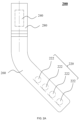
- FIG. 2B is a front view of the first housing 260 according to this embodiment of this specification.
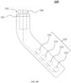
- FIG. 2C is a top view of the first housing 260 according to this embodiment of this specification.
- the first housing 260 may include a first interface 262.
- the first housing 260 may further include contacts 266.
- the first housing 260 may further include an angle sensor (not shown in FIG. 2B and FIG. 2C ).
- the first interface 262 may be a mounting interface of the first housing 260 and the second housing 280. In some embodiments, the first interface 262 may be circular. The first interface 262 may be rotatably connected to the second housing 280. When the first housing 260 is mounted on the second housing 280, the first housing 260 may be rotated relative to the second housing 280 to adjust an angle of the first housing 260 relative to the second housing 280, thereby adjusting an angle of the microphone array 220.
- a first magnetic apparatus 263 may be disposed on the first interface 262.
- the first magnetic apparatus 263 may be disposed at a position of the first interface 262 close to the second housing 280.
- the first magnetic apparatus 263 may generate magnetic adherence to achieve a detachable connection to the second housing 280.
- the first housing 260 may be quickly connected to the second housing 280 by the adherence.
- the first housing 260 may also be rotated relative to the second housing 280 to adjust the angle of the microphone array 220. Due to the adherence, the connection between the first housing 260 and the second housing 280 may still be maintained while the first housing 260 is rotated relative to the second housing 280.
- a first positioning apparatus (not shown in FIG. 2B and FIG. 2C ) may also be disposed on the first interface 262.
- the first positioning apparatus may be an externally protruding positioning step or an internally extending positioning hole.
- the first positioning apparatus may cooperate with the second housing 280 to implement quick mounting of the first housing 260 and the second housing 280.
- the first housing 260 may further include contacts 266.
- the contacts 266 may be mounted on the first interface 262.
- the contacts 266 may protrude externally from the first interface 262.
- the contacts 266 may be elastically connected to the first interface 262.
- the contacts 266 may be in communication with the M microphones 222 in the microphone array 220.
- the contacts 266 may be made of an elastic metal to implement data transmission.
- the microphone array 220 may be in communication with the computing apparatus 240 through the contacts 266.
- the contacts 266 may be distributed in a circular shape.
- an angle sensor (not shown in FIG. 2B and FIG. 2C ) may be further disposed on the first housing 260.
- the angle sensor may be in communication with the contacts 266, thereby implementing a communication connection to the computing apparatus 240.
- the angle sensor may collect angle data of the first housing 260 to determine an angle at which the microphone array 220 is located, to provide reference data for subsequent calculation of a voice presence probability.
- FIG. 2D is a front view of the second housing 280 according to this embodiment of this specification.
- FIG. 2E is a bottom view of the second housing 280 according to this embodiment of this specification.
- the second housing 280 may include a second interface 282.
- the second housing 280 may further include a guide rail 286.
- the second interface 282 may be a mounting interface of the second housing 280 and the first housing 260. In some embodiments, the second interface 282 may be circular. The second interface 282 may be rotatably connected to the first interface 262 of the first housing 260. When the first housing 260 is mounted on the second housing 280, the first housing 260 may be rotated relative to the second housing 280 to adjust the angle of the first housing 260 relative to the second housing 280, thereby adjusting the angle of the microphone array 220.
- a second magnetic apparatus 283 may be disposed on the second interface 282.
- the second magnetic apparatus 283 may be disposed at a position of the second interface 282 close to the first housing 260.
- the second magnetic apparatus 283 may generate magnetic adherence to achieve a detachable connection to the first interface 262.
- the second magnetic apparatus 283 may be used in cooperation with the first magnetic apparatus 263.
- the first housing 260 approaches the second housing 280, the first housing 260 may be quickly mounted on the second housing 280 by the adherence between the second magnetic apparatus 283 and the first magnetic apparatus 263.
- a position of the second magnetic apparatus 283 is opposite to a position of the first magnetic apparatus 263.
- the first housing 260 may also be rotated relative to the second housing 280 to adjust the angle of the microphone array 220. Under the adherence, the connection between the first housing 260 and the second housing 280 can still be maintained while the first housing 260 is rotated relative to the second housing 280.
- a second positioning apparatus (not shown in FIG. 2D and FIG. 2E ) may also be disposed on the second interface 282.
- the second positioning apparatus may be an externally protruding positioning step or an internally extending positioning hole.
- the second positioning apparatus may cooperate with the first positioning apparatus of the first housing 260 to implement quick mounting of the first housing 260 and the second housing 280.
- the first positioning apparatus is the positioning step
- the second positioning apparatus may be the positioning hole.
- the second positioning apparatus may be the positioning step.
- the second housing 280 may further include a guide rail 286.
- the guide rail 286 may be mounted on the second interface 282.
- the guide rail 286 may be in communication with the computing apparatus 240.
- the guide rail 286 may be made of a metal material to implement data transmission.
- the contacts 266 may contact the guide rail 286 to form a communication connection, to implement the communication between the microphone array 220 and the computing apparatus 240 and implement data transmission. As described above, the contacts 266 may be elastically connected to the first interface 262.
- the contacts 266 may contact the guide rail 286 under elastic force of the elastic connection, so that a reliable communication may be implemented.
- the guide rail 286 may be distributed in a circular shape.
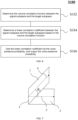
- FIG. 3 is a flowchart of a voice activity detection method P100 according to some embodiments of this specification.
- the method P100 may calculate a voice presence probability of a target voice signal being present in a microphone signal.
- a processor 242 may perform the method P100.
- the method P100 may include: S120. Obtain microphone signals output by M microphones 222.
- each microphone 222 may output a corresponding microphone signal.
- the M microphones 222 correspond to M microphone signals.
- the method P100 may perform the calculation based on all of the M microphone signals or may perform the calculation based on a part of the microphone signals. Therefore, the microphone signals may include the M microphone signals corresponding to the M microphones 222 or a part of microphone signals.
- the microphone signals may include the M microphone signals corresponding to the M microphones 222 or a part of microphone signals.
- the microphone signal may be a time domain signal.
- a microphone signal at a time t is marked as x ( t ).
- the microphone signal x ( t ) may be a signal vector formed by the M microphone signals.
- the microphone signal x ( t ) is a time domain signal.
- a computing apparatus 240 may further perform a spectral analysis on the microphone signal x ( t ). Specifically, the computing apparatus 240 may perform a Fourier transform based on the time domain signal x ( t ) of the microphone signal to obtain a frequency domain signal x f,t of the microphone signal.
- the microphone signal x f,t in frequency domain is described.
- x f,t may be an M-dimensional signal vector formed by M microphone signals.
- the microphone 222 may capture noise in an ambient environment and output a noise signal, and may also capture a voice of a target user and output a target voice signal.
- the microphone signal includes only the noise signal.
- the microphone signal includes the target voice signal and the noise signal.
- s f , t is a complex amplitude of the target voice signal.
- s f,t may be an L ⁇ 1-dimensional vector.
- the target steering vector P is an M ⁇ L-dimensional matrix.
- f 0 is a carrier frequency
- d is a distance (spacing) between adjacent microphones 222
- c is a speed of sound
- ⁇ 1 , ..., ⁇ L are incident angles between the L target voice signal sources and microphones 222 respectively.
- angles of the target voice signal source s f , t are generally distributed in a group of specific angle ranges. Therefore, ⁇ 1 , ..., ⁇ L are known.
- Relative position relationships, such as relative distances or relative coordinates, of the M microphones 222 are prestored in the computing apparatus 240. To be specific, the distance d between adjacent microphones 222 is prestored in the computing device 240. In other words, the target steering vector P may be prestored in the computing apparatus 240.
- the noise signal d f,t may be an M-dimensional signal vector captured by the M microphones 222.
- the noise signal d f,t may be expressed as the following formula: d f,t is the complex amplitude of the noise signal.
- d f,t may be an N ⁇ 1-dimensional vector.
- the noise steering vector Q is an M ⁇ N-dimensional matrix. Due to irregularity of the noise signal, the noise signal d f,t and the noise steering vector Q are unknown.
- the microphone 222 may capture both the target voice signal s f , t and the noise signal d f,t .
- the target voice signal s f,t and the noise signal d f,t are two non-overlapping signals. Therefore, a target subspace in which the target voice signal s f,t is located and a noise subspace in which the noise signal d f,t is located are two non-overlapping subspaces. Therefore, when the target voice signal s f,t is absent in the microphone signal x f,t , the microphone signal x f,t includes only the noise signal d f,t .
- the signal subspace in which the microphone signal x f,t is located and the target subspace in which the target voice signal s f , t is located are two non-overlapping subspaces, and a linear correlation between the signal subspace and the target subspace is low or zero.
- the microphone signal x f,t includes both the target voice signal s f , t and the noise signal d f,t .
- the signal subspace in which the microphone signal x f,t is located and the target subspace in which the target voice signal s f , t is located are two overlapping subspaces, and the linear correlation between the signal subspace and the target subspace is relatively high. Therefore, by calculating the linear correlation between the signal subspace in which the microphone signal x f,t is located and the target subspace in which the target voice signal s f , t is located, the computing apparatus 240 may determine a voice presence probability of the target voice signal s f,t being present in the microphone signal x f,t .
- the signal subspace is defined as span ( U s ) and the target subspace is defined as span ( U t ).
- the method P100 may further include: S140. Determine, based on the microphone signal(s) x f,t , a signal subspace span ( U s ) formed by the microphone signal x f,t .
- determining the signal subspace span ( U s ) refers to determining a basis matrix U s of the signal subspace span ( U s ).
- the computing apparatus 240 may determine the basis matrix U s of the signal subspace span ( U s ) based on a sample covariance matrix of the microphone signal x f,t .
- the sample covariance matrix is defined as M x .
- FIG. 4 is a flowchart for determining the basis matrix U s of the signal subspace span ( U s ) according to an embodiment of this specification. The corresponding step shown in FIG.
- step S140 may include the following steps.
- eigendecomposition is performed on the sample covariance matrix M x to obtain a plurality of eigenvalues of the sample covariance matrix M x .
- the sample covariance matrix M x is an M ⁇ M-dimensional matrix.
- the M eigenvalues correspond to M eigenvectors.
- the M eigenvectors are defined as u 1 , u 2 , ⁇ , u q , u q +1 , ⁇ , u M .
- the M eigenvalues correspond to the M eigenvectors on a one-to-one basis.
- the computing apparatus 240 may use a matrix formed by the M eigenvectors as the basis matrix U s of the signal subspace span ( U s ). In some embodiments, the computing apparatus 240 may use a matrix formed by a part of the M eigenvectors as the basis matrix U s of the signal subspace span ( U s ).
- the computing apparatus 240 can use a matrix formed by q eigenvectors u 1 , u 2 , ⁇ , u q corresponding to q different eigenvalues ⁇ 1 , ⁇ 2 , ⁇ , ⁇ q as the basis matrix U s of the signal subspace span ( U s ).
- the basis matrix U s of the signal subspace span ( U s ) is an M ⁇ q full-column-rank matrix.
- the computing apparatus 240 may determine the basis matrix U s of the signal subspace span ( U s ) based on the signal steering vector [ P , Q ] of the microphone signal x f,t .
- FIG. 5 is another flowchart for determining the basis matrix U s of the signal subspace span ( U s ) according to an embodiment of this specification. The corresponding step shown in FIG. 5 is that the computing apparatus 240 determines the basis matrix U s of the signal subspace span ( U s ) based on the signal steering vector [ P,Q ] of the microphone signal x f,t .
- step S140 may include: S148.
- the target steering vector P may be prestored in the computing apparatus 240, and the noise steering vector Q is unknown.
- the computing apparatus 240 may estimate the noise steering vector Q based on the spatial estimation method to determine the signal steering vector [ P,Q ].
- the spatial estimation method may include at least one of a DOA estimation method (also referred to as direction of arrival estimation) and a spatial spectrum estimation method.
- the DOA estimation method may include but is not limited to a linear spectrum estimation (for example, a periodogram method), a maximum likelihood spectrum estimation method, a maximum entropy method, a MUSIC algorithm (Multiple Signal Classification algorithm, also referred to as a multiple signal classification algorithm), an ESPRIT algorithm (Estimating signal parameters viarotational invariance techniques, also referred to as a viarotational invariance method), or the like.
- a linear spectrum estimation for example, a periodogram method
- a maximum likelihood spectrum estimation method for example, a maximum likelihood spectrum estimation method, a maximum entropy method
- a MUSIC algorithm Multiple Signal Classification algorithm, also referred to as a multiple signal classification algorithm
- an ESPRIT algorithm Estimatimating signal parameters viarotational invariance techniques, also referred to as a viarotational invariance method
- the basis matrix U s of the signal subspace span ( U s ) is an M ⁇ (L+N)-dimensional full-column-rank matrix.
- the method P100 may further include: S160. Determine the target subspace span ( U t ) formed by the target voice signal.
- the determining of the target subspace span ( U t ) refers to determining the basis matrix U t of the target subspace span ( U t ).
- the target steering vector P may be prestored in the computing apparatus.
- Step S160 may be: The computing apparatus 240 determines that a preset target steering vector P corresponding to the target voice signal is the basis matrix U t of the target subspace span ( U t ).
- the basis matrix U t of the target subspace span ( U t ) is an M ⁇ L-dimensional full-column-rank matrix.
- the method P100 may further include: S180. Determine, based on the linear correlation between the signal subspace span ( U s ) and the target subspace span ( U t ), the voice presence probability ⁇ of the target voice signal being present in the microphone signal x f,t , and output the voice presence probability.
- the computing apparatus 240 may calculate the linear correlation between the signal subspace span ( U s ) and the target subspace span ( U t ) by calculating the linear correlation between the signal subspace span ( U s ) and a volume correlation function of the target subspace span ( U t ).
- FIG. 6 is a flowchart for calculating the voice presence probability ⁇ according to an embodiment of this specification.
- FIG. 6 shows step S180.
- step S180 may include: S182. Determine the volume correlation function between the signal subspace span ( U s ) and the target subspace span ( U t ).
- the volume correlation function between the signal subspace span ( U s ) and the target subspace span ( U t ) may be a volume correlation function vcc ( U s , U t ) between the basis matrix U s of the signal subspace span ( U s ) and the basis matrix U t of the target subspace span ( U t ).
- FIG. 7 is a schematic diagram of a spatial principal angle according to an embodiment of this specification.
- two planes plane 1 and plane 2 intersecting in a three-dimensional space have a common basis vector 3.
- a first principal angle ⁇ 1 thereof is 0, and a second principal angle ⁇ 2 thereof is equal to an included angle of the other basis vectors (basis vector 4 and basis vector 5) thereof. Therefore, a volume correlation function between the plane 1 and the plane 2 is 0.
- the volume correlation function vcc ( U s , U t ) has the following properties: When the two subspaces (the signal subspace span ( U s ) and the target subspace span ( U t ) respectively spanned by the basis matrix U s and the basis matrix U t are linearly correlated, that is, when the signal subspace span ( U s ) and the target subspace span ( U t ) have other commonly owned basis vectors in addition to a zero vector, a sine value of at least one spatial principal angle in ⁇ 1 , ⁇ 2 , ⁇ , ⁇ min ⁇ q,L ⁇ is 0, and the volume correlation function vcc ( U s , U t ) is 0.
- the volume correlation function vcc ( U s , U t ) provides a measure for the linear correlation between the signal subspace span ( U s ) and the target subspace span ( U t ) respectively spanned by the two basis matrices U s and U t .
- a problem of voice activity detection for the microphone signal x f,t can be transformed into a problem of the volume correlation function vcc ( U s , U t ) between the two basis matrices U s and U t of the signal subspace span ( U s ) and the target subspace span ( U t ) by using an inherent geometric structure between the target subspace span ( U t ) and the signal subspace span ( U s ).
- the volume correlation function vcc ( U s ,U t ) As can be learned from the definition and properties of the volume correlation function vcc ( U s ,U t ), if the value of the volume correlation function vcc ( U s , U t ) is closer to 1, a degree of overlapping between the signal subspace span ( U s ) and the target subspace span ( U t ) is lower, orthogonality between the two subspaces is higher, and the linear correlation coefficient between the signal subspace span ( U s ) and the target subspace span ( U t ) is lower. In this case, it is more possible that the signal in the microphone signal x f,t is a noise signal, and these components should be suppressed as far as possible.
- the linear correlation coefficient r is negatively correlated with the volume correlation function vcc ( U s , U t ).
- step S184 may include one of the following cases: determining that the volume correlation function vcc ( U s , U t ) is greater than a first threshold a, and determining that the linear correlation coefficient r is 0; determining that the volume correlation function vcc ( U s , U t ) is less than a second threshold b, and determining that the linear correlation coefficient r is 1; and determining that the volume correlation function vcc ( U s , U t ) is between the first threshold a and the second threshold b, and determining that the linear correlation coefficient r is between 0 and 1 and that the linear correlation coefficient r is a negative correlation function of the volume correlation function vcc ( U s , U t ), where the second threshold b is less than the first threshold a.
- f ( vcc ( U s , U t )) may be a function linearly negatively correlated with vcc ( U s , U t ).
- the computing apparatus 240 can calculate the linear correlation between the signal subspace span ( U s ) and the target subspace span ( U t ) by calculating the volume correlation function vcc ( U s , U t ) of the basis matrices U s and U t . If the volume correlation function vcc ( U s , U t ) is higher, it proves that the linear correlation between the signal subspace span ( U s ) and the target subspace span ( U t ) is lower, and the degree of overlapping between the signal subspace span ( U s ) and the target subspace span ( U t ) is lower.
- the degree of overlapping between the microphone signal x f,t and the target voice signal is lower.
- the voice presence probability A of the target voice signal being present in the microphone signal x f,t is lower.
- the volume correlation function vcc ( U s , U t ) is lower, it proves that the linear correlation between the signal subspace span ( U s ) and the target subspace span ( U t ) is higher, and the degree of overlapping between the signal subspace span ( U s ) and the target subspace span ( U t ) is higher.
- the degree of overlapping between the microphone signal x f,t and the target voice signal is higher.
- the voice presence probability ⁇ of the target voice signal being present in the microphone signal x f,t is higher.
- the voice enhancement system may also be applied to an electronic device 200.
- the voice enhancement system may include a computing apparatus 240.
- the voice enhancement system may be applied to the computing apparatus 240.
- the voice enhancement system may operate on the computing apparatus 240.
- the voice enhancement system may include a hardware device having a data information processing function and a program required to drive the hardware device to work.
- the voice enhancement system may also be only a hardware device having a data processing capability or only a program running in a hardware device.
- the voice enhancement system may store data or an instruction for performing a voice enhancement method described in this specification and may execute the data and/or the instruction.
- the voice enhancement system may obtain a microphone signal from a microphone array 220 based on a communication and execute the data or the instruction of the voice enhancement method described in this specification.
- the voice enhancement method is described in other parts of this specification. For example, the voice enhancement method is described in the description of FIG. 8 .
- a storage medium 243 may further include at least one instruction set stored in a data storage apparatus and used for performing voice enhancement calculation on the microphone signal.
- the instruction may be computer program code.
- the computer program code may include a program, a routine, an object, a component, a data structure, a process, a module, or the like for performing the voice enhancement method provided in this specification.
- a processor 242 may read the at least one instruction set and perform, based on the at least one instruction set, the voice enhancement method provided in this specification. The processor 242 may perform all steps included in the voice enhancement method.
- FIG. 8 is a flowchart of a voice enhancement method P200 according to an embodiment of this specification.
- the method P200 may perform voice enhancement on a microphone signal.
- a processor 242 may perform the method P200.
- the method P200 may include the following steps.
- step S120 This step is the same as step S120, and is not described herein again.
- the filter coefficient vector ⁇ f,t may be an M ⁇ 1-dimensional vector.
- a computing apparatus 240 may determine the filter coefficient vector ⁇ f,t based on an MVDR method.
- step S260 may include: determining noise covariance matrices M f , t n of the microphone signals x f,t based on the voice presence probability ⁇ ; and determining the filter coefficient vector ⁇ f,t based on the MVDR method and the noise covariance matrices M f , t n .
- the computing apparatus 240 may determine the filter coefficient vector ⁇ f,t based on a fixed beam method.
- the filter coefficient vector ⁇ f,t includes a vector formed by the filter coefficient ⁇ k,f,t corresponding to the target microphone signal x k,f,t and the filter coefficients corresponding to the other microphone signals.
- the target microphone signal x k,f,t may include one of the microphone signals x f,t that has a highest signal-to-noise ratio.
- the target microphone signal x k,f,t may be a microphone signal closest to a target voice signal source (such as a mouth).
- k may be prestored in the computing apparatus 240.
- the voice activity detection system and method P100, and the voice enhancement system and method P200 provided in this specification are used for the microphone array 220 formed by a plurality of microphones 222.
- the voice activity detection system and method P100, and the voice enhancement system and method P200 can obtain the microphone signal x f,t captured by the microphone array 220.
- the microphone signal x f,t may include a noise signal, and may also include a target voice signal.
- the target voice signal and the noise signal are two non-overlapping signals.
- a target subspace span ( U t ) in which the target voice signal is located and a noise subspace in which the noise signal is located are two non-overlapping subspaces.
- the microphone signal x f,t When the target voice signal is absent in the microphone signal x f,t , the microphone signal x f,t includes only the noise signal. In this case, a signal subspace span ( U s ) in which the microphone signal x f,t is located and the target subspace span ( U t ) in which the target voice signal is located are two non-overlapping subspaces, and a linear correlation between the signal subspace span ( U s ) and the target subspace span ( U t ) is low.
- the microphone signal x f,t includes both the target voice signal and the noise signal.
- the signal subspace span ( U s ) in which the microphone signal x f,t is located and the target subspace span ( U t ) in which the target voice signal is located are two overlapping subspaces, and the linear correlation between the signal subspace span ( U s ) and the target subspace span ( U t ) is high. Therefore, by calculating the linear correlation between the signal subspace span ( U s ) in which the microphone signal x f,t is located and the target subspace span ( U t ) in which the target voice signal is located, the voice activity detection method P100 and system provided in this specification can determine a voice presence probability ⁇ of the target voice signal being present in the microphone signal x f,t .
- the voice enhancement method P200 and system can calculate a filter coefficient vector ⁇ f,t based on the voice presence probability ⁇ to perform voice enhancement on the microphone signal x f,t .
- the voice activity detection system and method P100, and the voice enhancement system and method P200 can improve calculation precision of the voice presence probability ⁇ and further improve a voice enhancement effect.
- the non-transitory storage medium stores at least one set of executable instructions for voice activity detection, and when the executable instructions are executed by a processor, the executable instructions instruct the processor to implement steps of the voice activity detection method P100 described in this specification.
- each aspect of this specification may be further implemented in a form of a program product, where the program product includes program code.
- the program product operates on a computing device (for example, the computing apparatus 240), the program code may be used to enable the computing device to perform steps of voice activity detection described in this specification.
- the program product for implementing the foregoing method may use a portable compact disc read-only memory (CD-ROM) including program code, and can run on the computing device.
- CD-ROM portable compact disc read-only memory
- a readable storage medium may be any tangible medium containing or storing a program, and the program may be used by or in connection with an instruction execution system (for example, the processor 242).
- the program product may use any combination of one or more readable media.
- the readable medium may be a readable signal medium or a readable storage medium.
- the readable storage medium may be but is not limited to an electronic, magnetic, optical, electromagnetic, infrared, or semi-conductor system, apparatus, or device, or any combination thereof.
- the readable storage medium include: an electrical connection having one or more conducting wires, a portable diskette, a hard disk, a random access memory (RAM), a read-only memory (ROM), an erasable programmable read-only memory (EPROM or Flash memory), an optical fiber, a portable compact disc read-only memory (CD-ROM), an optical storage device, a magnetic storage device, or any appropriate combination thereof.
- the computer-readable storage medium may include a data signal propagated in a baseband or as part of a carrier, where the data signal carries readable program code. The propagated data signal may be in a plurality of forms, including but not limited to an electromagnetic signal, an optical signal, or any appropriate combination thereof.
- the readable storage medium may be any readable medium other than the readable storage medium.
- the readable medium may send, propagate, or transmit a program to be used by or in combination with an instruction execution system, apparatus, or device.
- the program code contained in the readable storage medium may be transmitted by using any appropriate medium, including but not limited to wireless, wired, optical cable, RF, or the like, or any appropriate combination thereof.
- the program code for performing operations in this specification may be compiled in any combination of one or more programming languages.
- the programming languages include object-oriented programming languages such as Java and C++, and further include conventional procedural programming languages such as a "C" language or a similar programming language.
- the program code may be fully executed on the computing device, partially executed on the computing device, executed as an independent software package, partially executed on the computing device and partially executed on a remote computing device, or fully executed on a remote computing device.
Landscapes
- Engineering & Computer Science (AREA)
- Health & Medical Sciences (AREA)
- Acoustics & Sound (AREA)
- Physics & Mathematics (AREA)
- Signal Processing (AREA)
- Human Computer Interaction (AREA)
- Audiology, Speech & Language Pathology (AREA)
- Computational Linguistics (AREA)
- Multimedia (AREA)
- Otolaryngology (AREA)
- Quality & Reliability (AREA)
- General Health & Medical Sciences (AREA)
- Circuit For Audible Band Transducer (AREA)
Abstract
Description
- This specification relates to the field of target voice signal processing technologies, and in particular, to a voice activity detection method and system, and a voice enhancement method and system.
- In the voice enhancement technology based on a beamforming algorithm, and especially in the minimum variance distortionless response (MVDR) adaptive beamforming algorithm, it is very important to solve a noise covariance matrix -- a parameter describing a noise statistics feature relationship between different microphones. A main method in the existing technologies is to calculate a noise covariance matrix based on a voice presence probability method, for example, estimating a voice presence probability by using a voice activity detection (VAD) method, and then calculate the noise covariance matrix. However, accuracy of estimating the voice presence probability in the existing technologies is not high enough, resulting in low precision of estimating the noise covariance matrix and further causing a poor voice enhancement effect of the MVDR algorithm. Especially when the quantity of microphones is low, for example, less than 5, the effect deteriorates sharply. Therefore, the MVDR algorithm in the existing technologies is mainly used in a microphone array device having a large quantity of microphones with large spaces, such as a mobile phone and a smart speaker, but the voice enhancement effect is poor for a device having a small quantity of microphones with small spacings, such as a headset.
- In light of the foregoing, a voice activity detection method and system, and a voice enhancement method and system having high precision need to be provided.
- This specification provides a voice activity detection method and system, and a voice enhancement method and system having higher precision.
- In one aspect, the present disclosure provides a voice activity detection method, the method is used for M microphones distributed in a preset array shape, where M is an integer greater than 1, the method includes: obtaining microphone signals output by the M microphones; determining, based on the microphone signals, a signal subspace formed by the microphone signals; determining a target subspace formed by a target voice signal; and determining, based on a linear correlation between the signal subspace and the target subspace, a voice presence probability of the target voice signal being present in the microphone signals, and outputting the voice presence probability.
- In some embodiments, the determining, based on the microphone signals, of the signal subspace formed by the microphone signal includes: determining a sample covariance matrix of the microphone signals based on the microphone signals; performing eigendecomposition on the sample covariance matrix to determine a plurality of eigenvectors of the sample covariance matrix; and using a matrix formed by at least some eigenvectors of the plurality of eigenvectors as a basis matrix of the signal subspace.
- In some embodiments, the determining, based on the microphone signals, of the signal subspace formed by the microphone signals includes: determining a signal steering vector of the microphone signals by determining an azimuth of a signal source of the microphone signals based on the microphone signals by using a spatial estimation method, where the spatial estimation method includes at least one of a direction of arrival (DOA) estimation method, or a spatial spectrum estimation method; and determining that the signal steering vector is a basis matrix of the signal subspace.
- In some embodiments, the determining of the target subspace formed by the target voice signal includes: determining that a preset target steering vector corresponding to the target voice signal is a basis matrix of the target subspace.
- In some embodiments, the determining, based on the linear correlation between the signal subspace and the target subspace, of the voice presence probability of the target voice signal being present in the microphone signal, and outputting of the voice presence probability includes: determining a volume correlation function between the signal subspace and the target subspace; determining a linear correlation coefficient between the signal subspace and the target subspace based on the volume correlation function, where the linear correlation coefficient is negatively correlated with the volume correlation function; and using the linear correlation coefficient as the voice presence probability, and outputting the voice presence probability.
- In some embodiments, the determining of the linear correlation coefficient between the signal subspace and the target subspace based on the volume correlation function includes one of the following steps: determining that the volume correlation function is greater than a first threshold, and determining that the linear correlation coefficient is 0; determining that the volume correlation function is less than a second threshold, and determining that the linear correlation coefficient is 1, where the second threshold is less than the first threshold; and determining that the volume correlation function is between the first threshold and the second threshold, and determining that the linear correlation coefficient is between 0 and 1 and that the linear correlation coefficient is a negative correlation function of the volume correlation function.
- In a second aspect, the present disclosure provides a voice activity detection system, the voice activity detection system includes: at least one storage medium storing at least one instruction set for voice activity detection; and at least one processor in communication with the at least one storage medium, where when the voice activity detection system is in operation, the at least one processor reads the at least one instruction set and implements the voice activity detection method according to the first aspect.
- In a third aspect, the present disclosure provides a voice enhancement method, characterized in that the voice enhancement method is used for M microphones distributed in a preset array shape, where M is an integer greater than 1, the method includes: obtaining microphone signals output by the M microphones; determining, based on the voice activity detection method according to the first asoect, a voice presence probability of a target voice signal being present in the microphone signals; determining, based on the voice presence probability, filter coefficient vectors corresponding to the microphone signals; and combining the microphone signals based on the filter coefficient vectors to obtain a target audio signal and output the target audio signal.
- In some embodiments, the determining, based on the voice presence probability, of the filter coefficient vectors corresponding to the microphone signals includes: determining noise covariance matrices of the microphone signals based on the voice presence probability; and determining the filter coefficient vectors based on a minimum variance distortionless response (MVDR) method and the noise covariance matrices.
- In some embodiments, the determining, based on the voice presence probability, of the filter coefficient vectors corresponding to the microphone signals includes: using the voice presence probability as a filter coefficient corresponding to a target microphone signal of the microphone signals, where the target microphone signal includes one of the microphone signals that has a highest signal-to-noise ratio; and determining that filter coefficients corresponding to other microphone signals than the target microphone signal among the microphone signals are 0, where the filter coefficient vectors include vectors formed by the filter coefficient corresponding to the target microphone signal and the filter coefficients corresponding to the other microphone signals.
- In a fourth aspect, the present disclosure provides a voice enhancement system, the voice enhancement system includes: at least one storage medium storing at least one instruction set for voice enhancement; and at least one processor in communication with the at least one storage medium, where when the voice enhancement system is in operation, the at least one processor reads the at least one instruction set and implements the voice enhancement method according to the third aspect.
- As can be known from the foregoing technical solutions, the voice activity detection method and system, and the voice enhancement method and system provided in this specification are used for a microphone array including a plurality of microphones. The microphone array can capture both a noise signal and a target voice signal, and output a microphone signal. The target voice signal and the noise signal are two non-overlapping signals. A target subspace in which the target voice signal is located and a noise subspace in which the noise signal is located are two non-overlapping subspaces. When the target voice signal is absent in the microphone signal, the microphone signal includes only the noise signal. In this case, a signal subspace in which the microphone signal is located and the target subspace in which the target voice signal is located are two non-overlapping subspaces, and a linear correlation between the signal subspace and the target subspace is low. When the target voice signal is present in the microphone signal, the microphone signal includes both the target voice signal and the noise signal. In this case, the signal subspace in which the microphone signal is located and the target subspace in which the target voice signal is located are two overlapping subspaces, and the linear correlation between the signal subspace and the target subspace is high. Therefore, by calculating the linear correlation between the signal subspace in which the microphone signal is located and the target subspace in which the target voice signal is located, the voice activity detection method and system provided in this specification can determine a voice presence probability of the target voice signal being present in the microphone signal. The voice enhancement method and system can calculate a filter coefficient based on the voice presence probability to perform voice enhancement on the microphone signal. The method and system can improve calculation precision of the voice presence probability and further improve a voice enhancement effect.
- Other functions of the voice activity detection method and system, and the voice enhancement method and system provided in this specification are partially described in the following description. Based on the description, the contents described in the following figures and examples would be obvious to a person of ordinary skill in the art. The inventive aspects of the voice activity detection method and system, and the voice enhancement method and system provided in this specification may be fully explained by practicing or using the method, apparatus, and a combination thereof in the following detailed examples.
- To describe the technical solutions in the embodiments of this specification more clearly, the following briefly describes the accompanying drawings required for describing the embodiments. Apparently, the accompanying drawings in the following description show merely some embodiments of this specification, and a person of ordinary skill in the art may still derive other drawings from these drawings without creative efforts.
-
FIG. 1 is a schematic hardware diagram of a voice activity detection system according to an embodiment of this specification; -
FIG. 2A is a schematic exploded structural diagram of an electronic device according to an embodiment of this specification; -
FIG. 2B is a front view of a first housing according to an embodiment of this specification; -
FIG. 2C is a top view of a first housing according to an embodiment of this specification; -
FIG. 2D is a front view of a second housing according to an embodiment of this specification; -
FIG. 2E is a bottom view of a second housing according to an embodiment of this specification; -
FIG. 3 is a flowchart of a voice activity detection method according to an embodiment of this specification; -
FIG. 4 is a flowchart for determining a basis matrix of a signal subspace according to an embodiment of this specification; -
FIG. 5 is another flowchart for determining a basis matrix of a signal subspace according to an embodiment of this specification; -
FIG. 6 is a flowchart for calculating a voice presence probability according to an embodiment of this specification; -
FIG. 7 is a schematic diagram of a spatial principal angle according to an embodiment of this specification; and -
FIG. 8 is a flowchart of a voice enhancement method according to an embodiment of this specification. - The following description provides specific application scenarios and requirements of this specification, to enable a person skilled in the art to make and use content of this specification. Various partial modifications to the disclosed embodiments are obvious to a person skilled in the art. General principles defined herein can be applied to other embodiments and applications without departing from the spirit and scope of this specification. Therefore, this specification is not limited to the illustrated embodiments, but is to be accorded the widest scope consistent with the claims.
- The terms used herein are only intended to describe specific exemplary embodiments and are not restrictive. For example, as used herein, singular forms "a", "an", and "the" may also include plural forms, unless otherwise explicitly specified in a context. When used in this specification, the terms "comprising", "including", and/or "containing" indicate presence of associated integers, steps, operations, elements, and/or components, but do not preclude presence of one or more other features, integers, steps, operations, elements, components, and/or groups or addition of other features, integers, steps, operations, elements, components, and/or groups to the system/method.
- In view of the following description, these features and other features of this specification, operations and functions of related elements of structures, and economic efficiency in combining and manufacturing components may be significantly improved. All of these form a part of this specification with reference to the drawings. However, it should be understood that the drawings are only for illustration and description purposes and are not intended to limit the scope of this specification. It should also be understood that the drawings are not drawn to scale.
- Flowcharts used in this specification show operations implemented by the system according to some embodiments of this specification. It should be understood that operations in the flowcharts may be implemented out of the order described herein. The operations may be implemented in a reverse order or simultaneously. In addition, one or more other operations may be added to the flowcharts, and one or more operations may be removed from the flowcharts.
- For ease of description, the following first explains terms that will appear in this specification.
- Minimum variance distortionless response (MVDR): It is an adaptive beamforming algorithm based on a maximum signal to interference plus noise ratio (SINR) criterion. The MVDR algorithm can adaptively minimize power of an array output in a desired direction while maximizing the signal to interference plus noise ratio. Its objective is to minimize a variance of a recorded signal. If a noise signal is uncorrelated with a desired signal, the variance of the recorded signal is a sum of variances of the desired signal and the noise signal. Therefore, the MVDR solution seeks to minimize this sum, thereby mitigating impact of the noise signal. Its principle is to choose an appropriate filter coefficient to minimize average power of the array output under a constraint that the desired signal is distortionless.
- Voice activity detection: It is a process of segmenting a target voice signal into a voice period and a non-voice period.
- Gaussian distribution: A normal distribution is also known as Gaussian distribution. A normal curve is bell-shaped, low at both ends, high in the middle, and left-right symmetric. Because the curve of the Gaussian distribution is bell-shaped, the curve is also often referred to as a bell-shaped curve. If a random variable X conforms to a with a mathematical expectation µ and a variance σ 2, the normal distribution is denoted as N(µ, σ 2). A probability density function of the random variable is an expected value µ of the normal distribution, which determines a position of the random variable. A standard deviation σ of the random variable determines an amplitude of the distribution. When µ = 0 and σ = 1, the normal distribution is a standard normal distribution.
-
FIG. 1 is a schematic hardware diagram of a voice activity detection system according to an embodiment of this specification. The voice activity detection system may be applied to anelectronic device 200. - In some embodiments, the
electronic device 200 may be a wireless head phone, a wired head phone, or an intelligent wearable device, for example, a device having an audio processing function such as smart glasses, a smart helmet, or a smart watch. Theelectronic device 200 may also be a mobile device, a tablet computer, a notebook computer, a built-in apparatus of a motor vehicle, or the like, or any combination thereof. In some embodiments, the mobile device may include a smart household device, a smart mobile device, or the like, or any combination thereof. For example, the smart mobile device may include a mobile phone, a personal digital assistant, a game device, a navigation device, an ultra-mobile personal computer (UMPC), or the like, or any combination thereof. In some embodiments, the smart household device may include a smart television, a desktop computer, or the like, or any combination thereof. In some embodiments, the built-in apparatus of the motor vehicle may include a vehicle-mounted computer, a vehicle-mounted (onboard) television, or the like. - In this specification, an example in which the
electronic device 200 is a head phone is used for description. The head phone may be a wireless head phone, or may be a wired head phone. As shown inFIG. 1 , theelectronic device 200 may include amicrophone array 220 and acomputing apparatus 240. - The
microphone array 220 may be an audio capture device of theelectronic device 200. Themicrophone array 220 may be configured to obtain a local audio, and output a microphone signal(s), that is, an electronic signal(s) carrying the audio information. Themicrophone array 220 may includeM microphones 222 distributed in a preset array shape. M is an integer greater than 1. TheM microphones 222 may be distributed evenly or unevenly. TheM microphones 222 may output microphone signals. TheM microphones 222 may output M microphone signals. Eachmicrophone 222 corresponds to one microphone signal. The M microphone signals are collectively referred to as the microphone signal. In some embodiments, theM microphones 222 may be distributed linearly. In some embodiments, theM microphones 222 may be distributed in an array of another shape, such as a circular array or a rectangular array. For ease of description, the linear distribution of theM microphones 222 is used as an example for description in the following description. In some embodiments, M may be any integer greater than 1, such as 2, 3, 4, 5, or even greater. In some embodiments, due to a space limitation, M may be an integer greater than 1 and not greater than 5, for example, in a product such as a head phone. When theelectronic device 200 is a head phone, a spacing betweenadjacent microphones 222 of theM microphones 222 may be 20 mm to 40 mm. In some embodiments, the spacing betweenadjacent microphones 222 may be smaller, for example, 10 mm to 20 mm. - In some embodiments, the
microphone 222 may be a bone conduction microphone that directly captures human body vibration signals. The bone conduction microphone may include a vibration sensor, for example, an optical vibration sensor or an acceleration sensor. The vibration sensor may capture a mechanical vibration signal (for example, a signal generated by a vibration generated by a skin or a bone when a user speaks), and convert the mechanical vibration signal into an electrical signal. Herein, the mechanical vibration signal mainly refers to a vibration propagated by a solid. The bone conduction microphone captures, by touching the skin or bone of the user with the vibration sensor or a vibration component connected to the vibration sensor, a vibration signal generated by the bone or skin when the user generates sound, and converts the vibration signal into an electrical signal. In some embodiments, the vibration sensor may be an apparatus that is sensitive to a mechanical vibration but insensitive to an air vibration (that is, a capability of responding to the mechanical vibration by the vibration sensor exceeds a capability of responding to the air vibration by the vibration sensor). Since the bone conduction microphone can directly pick a vibration signal of a sound generation part, the bone conduction microphone may reduce impact of ambient noise. - In some embodiments, the
microphone 222 may alternatively be an air conduction microphone that directly captures air vibration signals. The air conduction microphone captures an air vibration signal caused when the user generates sound, and converts the air vibration signal into an electrical signal. - In some embodiments, the
M microphones 222 may be M bone conduction microphones. In some embodiments, theM microphones 222 may alternatively be M air conduction microphones. In some embodiments, theM microphones 222 may include both bone conduction microphone(s) and air conduction microphone(s). Certainly, themicrophone 222 may alternatively be another type of microphone, for example, an optical microphone, a microphone receiving a myoelectric signal. - The
computing apparatus 240 may be in communication with themicrophone array 220. The communication herein may be a communication in any form and capable of directly or indirectly receiving information. In some embodiments, thecomputing apparatus 240 and themicrophone array 220 may transfer data to each other over a wireless communication connection. In some embodiments, thecomputing apparatus 240 and themicrophone array 220 may alternatively transfer data to each other over a direct connection by using a wire. In some embodiments, thecomputing apparatus 240 may alternatively be connected directly to another circuit by using a wire and hence connected indirectly to themicrophone array 220 to implement mutual data transfer. The direct connection between thecomputing apparatus 240 and themicrophone array 220 by using a wire is used as an example for description in this specification. - The
computing apparatus 240 may be a hardware device having a data information processing function. In some embodiments, the voice activity detection system may include thecomputing apparatus 240. In some embodiments, the voice activity detection system may be applied to thecomputing apparatus 240. In other words, the voice activity detection system may operate on thecomputing apparatus 240. The voice activity detection system may include a hardware device having a data information processing function and a program required to drive the hardware device to work. Certainly, the voice activity detection system may also be only a hardware device having a data processing capability or only a program executed by a hardware device. - The voice activity detection system may store data or an instruction for performing a voice activity detection method described in this specification, and may execute the data and/or the instruction. When the voice activity detection system runs on the
computing apparatus 240, the voice activity detection system may obtain the microphone signal from themicrophone array 220 based on the communication connection, and execute the data or the instruction of the voice activity detection method described in this specification, to calculate a voice presence probability of a target voice signal being present in a microphone signal. The voice activity detection method is described in other parts of this specification. For example, the voice activity detection method is introduced in the descriptions ofFIG. 3 to FIG. 8 . - As shown in
FIG. 1 , thecomputing apparatus 240 may include at least onestorage medium 243 and at least oneprocessor 242. In some embodiments, theelectronic device 200 may further include acommunications port 245 and aninternal communications bus 241. - The
internal communications bus 241 may connect different system components, including thestorage medium 243, theprocessor 242, and thecommunications port 245. - The
communications port 245 may be used for data communication between thecomputing apparatus 240 and the outside world. For example, thecomputing apparatus 240 may obtain the microphone signal from themicrophone array 220 through thecommunications port 245. - The at least one
storage medium 243 may include a data storage apparatus. The data storage apparatus may be a non-transitory storage medium, or may be a transitory storage medium. For example, the data storage apparatus may include one or more of a magnetic disk, a read-only memory (ROM), or a random access memory (RAM). When the voice activity detection system operates on thecomputing apparatus 240, thestorage medium 243 may further include at least one instruction set stored in the data storage apparatus, where the instruction set is used to perform voice activity detection on the microphone signal. The instruction is computer program code. The computer program code may include a program, a routine, an object, a component, a data structure, a process, a module, or the like for performing the voice activity detection method provided in this specification. - The at least one
processor 242 may be in communication with the at least onestorage medium 243 via theinternal communications bus 241. The communication connection may be a communication in any form and capable of directly or indirectly receiving information. The at least oneprocessor 242 is configured to execute the at least one instruction set. When the voice activity detection system may run on thecomputing apparatus 240, the at least oneprocessor 242 reads the at least one instruction set, and implements, based on the at least one instruction set, the voice activity detection method provided in this specification. Theprocessor 242 may perform all steps included in the voice activity detection method. Theprocessor 242 may be in a form of one or more processors. In some embodiments, theprocessor 242 may include one or more hardware processors, for example, a microcontroller, a microprocessor, a reduced instruction set computer (RISC), an application-specific integrated circuit (ASIC), an application-specific instruction set processor (ASIP), a central processing unit (CPU), a graphics processing unit (GPU), a physical processing unit (PPU), a microcontroller unit, a digital signal processor (DSP), a field programmable gate array (FPGA), an advanced RISC machine (ARM), a programmable logic device (PLD), any circuit or processor that can implement one or more functions, and the like, or any combination thereof. For illustration only, oneprocessor 242 in thecomputing apparatus 240 is described in this specification. However, it should be noted that thecomputing apparatus 240 in this specification may further include a plurality ofprocessors 242. Therefore, operations and/or method steps disclosed in this specification may be performed by one processor in this specification, or may be performed jointly by a plurality of processors. For example, if theprocessor 242 of thecomputing apparatus 240 in this specification performs step A and step B, it should be understood that step A and step B may also be performed jointly or separately by two different processors 242 (for example, the first processor performs step A, and the second processor performs step B, or the first processor and the second processor jointly perform step A and step B). -
FIG. 2A is a schematic exploded structural diagram of anelectronic device 200 according to an embodiment of this specification. As shown inFIG. 2A , theelectronic device 200 may include amicrophone array 220, acomputing apparatus 240, afirst housing 260, and asecond housing 280. - The
first housing 260 may be a mounting base of themicrophone array 220. Themicrophone array 220 may be mounted inside thefirst housing 260. A shape of thefirst housing 260 may be adaptively designed based on a distribution shape of themicrophone array 220. This is not limited in this specification. Thesecond housing 280 may be a mounting base of thecomputing apparatus 240. Thecomputing apparatus 240 may be mounted in thesecond housing 280. A shape of thesecond housing 280 may be adaptively designed based on a shape of thecomputing apparatus 240. This is not limited in this specification. When theelectronic device 200 is a head phone, thesecond housing 280 may be connected to a wearing part. Thesecond housing 280 may be connected to thefirst housing 260. As described above, themicrophone array 220 may be electrically connected to thecomputing apparatus 240. Specifically, themicrophone array 220 may be electrically connected to thecomputing apparatus 240 via the connection between thefirst housing 260 and thesecond housing 280. - In some embodiments, the
first housing 260 may be fixedly connected, for example, integrated, welded, riveted, or bonded, to thesecond housing 280. In some embodiments, thefirst housing 260 may be detachably connected to thesecond housing 280. Thecomputing apparatus 240 may be in communication withdifferent microphone arrays 220. Specifically, a difference between thedifferent microphone arrays 220 may lie in different quantities ofmicrophones 222 in themicrophone arrays 220, different array shapes, different spacings between themicrophones 222, different mounting angles of themicrophone arrays 220 in thefirst housing 260, different mounting positions of themicrophone arrays 220 in thefirst housing 260, or the like. Depending on different application scenarios, the user may changecorresponding microphone arrays 220, so that theelectronic device 200 may be applied to a wider range of scenarios. For example, when the user is closer to theelectronic device 200 in an application scenario, the user may replace themicrophone array 220 with amicrophone array 220 having a smaller microphone spacing. In another example, when the user is closer to theelectronic device 200 in an application scenario, the user may replace themicrophone array 220 with amicrophone array 220 having a larger microphone spacing and a larger microphone quantity. - The detachable connection may be a physical connection in any form, such as a threaded connection, a snap connection, or a magnetic connection. In some embodiments, there may be a magnetic connection between the
first housing 260 and thesecond housing 280. To be specific, thefirst housing 260 and thesecond housing 280 are detachably connected to each other by a magnetic apparatus. -
FIG. 2B is a front view of thefirst housing 260 according to this embodiment of this specification.FIG. 2C is a top view of thefirst housing 260 according to this embodiment of this specification. As shown inFIG. 2B andFIG. 2C , thefirst housing 260 may include afirst interface 262. In some embodiments, thefirst housing 260 may further includecontacts 266. In some embodiments, thefirst housing 260 may further include an angle sensor (not shown inFIG. 2B andFIG. 2C ). - The
first interface 262 may be a mounting interface of thefirst housing 260 and thesecond housing 280. In some embodiments, thefirst interface 262 may be circular. Thefirst interface 262 may be rotatably connected to thesecond housing 280. When thefirst housing 260 is mounted on thesecond housing 280, thefirst housing 260 may be rotated relative to thesecond housing 280 to adjust an angle of thefirst housing 260 relative to thesecond housing 280, thereby adjusting an angle of themicrophone array 220. - A first
magnetic apparatus 263 may be disposed on thefirst interface 262. The firstmagnetic apparatus 263 may be disposed at a position of thefirst interface 262 close to thesecond housing 280. The firstmagnetic apparatus 263 may generate magnetic adherence to achieve a detachable connection to thesecond housing 280. When thefirst housing 260 approaches thesecond housing 280, thefirst housing 260 may be quickly connected to thesecond housing 280 by the adherence. In some embodiments, after thefirst housing 260 is connected to thesecond housing 280, thefirst housing 260 may also be rotated relative to thesecond housing 280 to adjust the angle of themicrophone array 220. Due to the adherence, the connection between thefirst housing 260 and thesecond housing 280 may still be maintained while thefirst housing 260 is rotated relative to thesecond housing 280. - In some embodiments, a first positioning apparatus (not shown in
FIG. 2B andFIG. 2C ) may also be disposed on thefirst interface 262. The first positioning apparatus may be an externally protruding positioning step or an internally extending positioning hole. The first positioning apparatus may cooperate with thesecond housing 280 to implement quick mounting of thefirst housing 260 and thesecond housing 280. - As shown in
FIG. 2B andFIG. 2C , in some embodiments, thefirst housing 260 may further includecontacts 266. Thecontacts 266 may be mounted on thefirst interface 262. Thecontacts 266 may protrude externally from thefirst interface 262. Thecontacts 266 may be elastically connected to thefirst interface 262. Thecontacts 266 may be in communication with theM microphones 222 in themicrophone array 220. Thecontacts 266 may be made of an elastic metal to implement data transmission. When thefirst housing 260 is connected to thesecond housing 280, themicrophone array 220 may be in communication with thecomputing apparatus 240 through thecontacts 266. In some embodiments, thecontacts 266 may be distributed in a circular shape. When thefirst housing 260 is rotated relative to thesecond housing 280 after thefirst housing 260 is connected to thesecond housing 280, thecontacts 266 may also rotate relative to thesecond housing 280 and maintain a communication connection to thecomputing apparatus 240. - In some embodiments, an angle sensor (not shown in
FIG. 2B andFIG. 2C ) may be further disposed on thefirst housing 260. The angle sensor may be in communication with thecontacts 266, thereby implementing a communication connection to thecomputing apparatus 240. The angle sensor may collect angle data of thefirst housing 260 to determine an angle at which themicrophone array 220 is located, to provide reference data for subsequent calculation of a voice presence probability. -
FIG. 2D is a front view of thesecond housing 280 according to this embodiment of this specification.FIG. 2E is a bottom view of thesecond housing 280 according to this embodiment of this specification. As shown inFIG. 2D andFIG. 2E , thesecond housing 280 may include asecond interface 282. In some embodiments, thesecond housing 280 may further include aguide rail 286. - The
second interface 282 may be a mounting interface of thesecond housing 280 and thefirst housing 260. In some embodiments, thesecond interface 282 may be circular. Thesecond interface 282 may be rotatably connected to thefirst interface 262 of thefirst housing 260. When thefirst housing 260 is mounted on thesecond housing 280, thefirst housing 260 may be rotated relative to thesecond housing 280 to adjust the angle of thefirst housing 260 relative to thesecond housing 280, thereby adjusting the angle of themicrophone array 220. - A second
magnetic apparatus 283 may be disposed on thesecond interface 282. The secondmagnetic apparatus 283 may be disposed at a position of thesecond interface 282 close to thefirst housing 260. The secondmagnetic apparatus 283 may generate magnetic adherence to achieve a detachable connection to thefirst interface 262. The secondmagnetic apparatus 283 may be used in cooperation with the firstmagnetic apparatus 263. When thefirst housing 260 approaches thesecond housing 280, thefirst housing 260 may be quickly mounted on thesecond housing 280 by the adherence between the secondmagnetic apparatus 283 and the firstmagnetic apparatus 263. When thefirst housing 260 is mounted on thesecond housing 280, a position of the secondmagnetic apparatus 283 is opposite to a position of the firstmagnetic apparatus 263. In some embodiments, after thefirst housing 260 is connected to thesecond housing 280, thefirst housing 260 may also be rotated relative to thesecond housing 280 to adjust the angle of themicrophone array 220. Under the adherence, the connection between thefirst housing 260 and thesecond housing 280 can still be maintained while thefirst housing 260 is rotated relative to thesecond housing 280. - In some embodiments, a second positioning apparatus (not shown in
FIG. 2D andFIG. 2E ) may also be disposed on thesecond interface 282. The second positioning apparatus may be an externally protruding positioning step or an internally extending positioning hole. The second positioning apparatus may cooperate with the first positioning apparatus of thefirst housing 260 to implement quick mounting of thefirst housing 260 and thesecond housing 280. When the first positioning apparatus is the positioning step, the second positioning apparatus may be the positioning hole. When the first positioning apparatus is the positioning hole, the second positioning apparatus may be the positioning step. - As shown in
FIG. 2D andFIG. 2E , in some embodiments, thesecond housing 280 may further include aguide rail 286. Theguide rail 286 may be mounted on thesecond interface 282. Theguide rail 286 may be in communication with thecomputing apparatus 240. Theguide rail 286 may be made of a metal material to implement data transmission. When thefirst housing 260 is connected to thesecond housing 280, thecontacts 266 may contact theguide rail 286 to form a communication connection, to implement the communication between themicrophone array 220 and thecomputing apparatus 240 and implement data transmission. As described above, thecontacts 266 may be elastically connected to thefirst interface 262. Therefore, after thefirst housing 260 is connected to thesecond housing 280, thecontacts 266 may contact theguide rail 286 under elastic force of the elastic connection, so that a reliable communication may be implemented. In some embodiments, theguide rail 286 may be distributed in a circular shape. When thefirst housing 260 is rotated relative to thesecond housing 280 after thefirst housing 260 is connected to thesecond housing 280, thecontacts 266 may also rotate relative to theguide rail 286 and maintain a communication connection to theguide rail 286. -
FIG. 3 is a flowchart of a voice activity detection method P100 according to some embodiments of this specification. The method P100 may calculate a voice presence probability of a target voice signal being present in a microphone signal. Specifically, aprocessor 242 may perform the method P100. As shown inFIG. 3 , the method P100 may include:
S120. Obtain microphone signals output byM microphones 222. - As described above, each
microphone 222 may output a corresponding microphone signal. TheM microphones 222 correspond to M microphone signals. When calculating a voice presence probability of a target voice signal being present in a microphone signal, the method P100 may perform the calculation based on all of the M microphone signals or may perform the calculation based on a part of the microphone signals. Therefore, the microphone signals may include the M microphone signals corresponding to theM microphones 222 or a part of microphone signals. In the subsequent description of this specification, an example in which the microphone signals may include the M microphone signals corresponding to theM microphones 222 is used for description. - In some embodiments, the microphone signal may be a time domain signal. For ease of description, a microphone signal at a time t is marked as x(t). The microphone signal x(t) may be a signal vector formed by the M microphone signals. In this case, the microphone signal x(t) may be expressed as the following formula:

- The microphone signal x(t) is a time domain signal. In some embodiments, in step S120, a
computing apparatus 240 may further perform a spectral analysis on the microphone signal x(t). Specifically, thecomputing apparatus 240 may perform a Fourier transform based on the time domain signal x(t) of the microphone signal to obtain a frequency domain signal xf,t of the microphone signal. In the following description, the microphone signal xf,t in frequency domain is described. xf,t may be an M-dimensional signal vector formed by M microphone signals. In this case, the microphone signal xf,t may be expressed as the following formula:
- As described above, the
microphone 222 may capture noise in an ambient environment and output a noise signal, and may also capture a voice of a target user and output a target voice signal. When the target user does not speak, the microphone signal includes only the noise signal. When the target user speaks, the microphone signal includes the target voice signal and the noise signal. The microphone signal xf,t may be expressed as the following formula:
- s f,t is a complex amplitude of the target voice signal. In some embodiments, there is one target voice signal source around the
microphone 222. In some embodiments, there are L target voice signal sources around themicrophone 222. In this case, sf,t may be an L×1-dimensional vector. sf,t may be expressed as the following formula:
- The target steering vector P is an M×L-dimensional matrix. The target steering vector P may be expressed as the following formula:

adjacent microphones 222; c is a speed of sound; and θ 1, ..., θL are incident angles between the L target voice signal sources andmicrophones 222 respectively. In some embodiments, angles of the target voice signal source s f,t are generally distributed in a group of specific angle ranges. Therefore, θ 1, ..., θL are known. Relative position relationships, such as relative distances or relative coordinates, of theM microphones 222 are prestored in thecomputing apparatus 240. To be specific, the distance d betweenadjacent microphones 222 is prestored in thecomputing device 240. In other words, the target steering vector P may be prestored in thecomputing apparatus 240. - The noise signal df,t may be an M-dimensional signal vector captured by the
M microphones 222. The noise signal df,t may be expressed as the following formula: df,t is the complex amplitude of the noise signal. In some embodiments, there are N noise signal sources around themicrophone 222. In this case, df,t may be an N×1-dimensional vector. df,t may be expressed as the following formula:
- The noise steering vector Q is an M×N-dimensional matrix. Due to irregularity of the noise signal, the noise signal df,t and the noise steering vector Q are unknown.
- In some embodiments, formula (3) may also be expressed as follows:

- As described above, the
microphone 222 may capture both the target voice signal s f,t and the noise signal df,t. The target voice signal sf,t and the noise signal df,t are two non-overlapping signals. Therefore, a target subspace in which the target voice signal sf,t is located and a noise subspace in which the noise signal df,t is located are two non-overlapping subspaces. Therefore, when the target voice signal sf,t is absent in the microphone signal xf,t , the microphone signal xf,t includes only the noise signal df,t. In this case, the signal subspace in which the microphone signal xf,t is located and the target subspace in which the target voice signal s f,t is located are two non-overlapping subspaces, and a linear correlation between the signal subspace and the target subspace is low or zero. When the target voice signal s f,t is present in the microphone signal xf,t , the microphone signal x f,t includes both the target voice signal s f,t and the noise signal df,t. In this case, the signal subspace in which the microphone signal xf,t is located and the target subspace in which the target voice signal s f,t is located are two overlapping subspaces, and the linear correlation between the signal subspace and the target subspace is relatively high. Therefore, by calculating the linear correlation between the signal subspace in which the microphone signal xf,t is located and the target subspace in which the target voice signal s f,t is located, thecomputing apparatus 240 may determine a voice presence probability of the target voice signal sf,t being present in the microphone signal xf,t. For ease of description, the signal subspace is defined as span(Us ) and the target subspace is defined as span(Ut ). - As shown in
FIG. 3 , the method P100 may further include:
S140. Determine, based on the microphone signal(s) xf,t , a signal subspace span(Us ) formed by the microphone signal xf,t. - In some embodiments, determining the signal subspace span(Us ) refers to determining a basis matrix Us of the signal subspace span(Us ). In some embodiments, the
computing apparatus 240 may determine the basis matrix Us of the signal subspace span(Us ) based on a sample covariance matrix of the microphone signal xf,t. For ease of description, the sample covariance matrix is defined as Mx.FIG. 4 is a flowchart for determining the basis matrix Us of the signal subspace span(Us ) according to an embodiment of this specification. The corresponding step shown inFIG. 4 is that thecomputing apparatus 240 determines the basis matrix Us of the signal subspace span(Us ) based on the sample covariance matrix Mx of the microphone signal xf,t . As shown inFIG. 4 , step S140 may include the following steps. - S142. Determine the sample covariance matrix Mx of the microphone signal xf,t based on the microphone signal xf,t .
- The sample covariance matrix Mx may be expressed as the following formula:

- S144. Perform eigendecomposition on the sample covariance matrix Mx to determine a plurality of eigenvectors of the sample covariance matrix M 1.
- Further, eigendecomposition is performed on the sample covariance matrix Mx to obtain a plurality of eigenvalues of the sample covariance matrix Mx . The sample covariance matrix Mx is an M×M-dimensional matrix. A quantity of eigenvalues of the sample covariance matrix Mx is M, and the M eigenvalues may be expressed as the following formula:

- The M eigenvalues correspond to M eigenvectors. For ease of description, the M eigenvectors are defined as u 1,u 2,···,uq ,u q+1,···,uM. The M eigenvalues correspond to the M eigenvectors on a one-to-one basis.
- S146. Use at least some eigenvectors of the plurality of eigenvectors as the basis matrix Us of the signal subspace span(Us ).
- In some embodiments, the
computing apparatus 240 may use a matrix formed by the M eigenvectors as the basis matrix Us of the signal subspace span(Us ). In some embodiments, thecomputing apparatus 240 may use a matrix formed by a part of the M eigenvectors as the basis matrix Us of the signal subspace span(Us ). Because λq = λ q+1 = ··· = λM , thecomputing apparatus 240 can use a matrix formed by q eigenvectors u 1,u 2,···,uq corresponding to q different eigenvalues λ 1,λ 2,···,λq as the basis matrix Us of the signal subspace span(Us ). The basis matrix Us of the signal subspace span(Us ) is an M×q full-column-rank matrix. - In some embodiments, the
computing apparatus 240 may determine the basis matrix Us of the signal subspace span(Us ) based on the signal steering vector [P,Q] of the microphone signal xf,t.FIG. 5 is another flowchart for determining the basis matrix Us of the signal subspace span(Us ) according to an embodiment of this specification. The corresponding step shown inFIG. 5 is that thecomputing apparatus 240 determines the basis matrix Us of the signal subspace span(Us ) based on the signal steering vector [P,Q] of the microphone signal xf,t . As shown inFIG. 5 , step S140 may include:
S148. Determine the signal steering vector [P,Q] of the microphone signal(s) xf,t by determining an azimuth of a signal source of the microphone signal(s) xf,t based on the microphone signal(s) xf,t by using a spatial estimation method. - As described above, the target steering vector P may be prestored in the
computing apparatus 240, and the noise steering vector Q is unknown. Thecomputing apparatus 240 may estimate the noise steering vector Q based on the spatial estimation method to determine the signal steering vector [P,Q]. The spatial estimation method may include at least one of a DOA estimation method (also referred to as direction of arrival estimation) and a spatial spectrum estimation method. The DOA estimation method may include but is not limited to a linear spectrum estimation (for example, a periodogram method), a maximum likelihood spectrum estimation method, a maximum entropy method, a MUSIC algorithm (Multiple Signal Classification algorithm, also referred to as a multiple signal classification algorithm), an ESPRIT algorithm (Estimating signal parameters viarotational invariance techniques, also referred to as a viarotational invariance method), or the like. - S149. Determine that the signal steering vector [P,Q] is the basis matrix Us of the signal subspace span (Us ).
- In this case, the basis matrix Us of the signal subspace span(Us ) is an M×(L+N)-dimensional full-column-rank matrix.
- As shown in
FIG. 3 , the method P100 may further include:
S160. Determine the target subspace span(Ut ) formed by the target voice signal. - In some embodiments, the determining of the target subspace span(Ut ) refers to determining the basis matrix Ut of the target subspace span(Ut ). As described above, the target steering vector P may be prestored in the computing apparatus. Step S160 may be: The
computing apparatus 240 determines that a preset target steering vector P corresponding to the target voice signal is the basis matrix Ut of the target subspace span(Ut ). The basis matrix Ut of the target subspace span(Ut ) is an M×L-dimensional full-column-rank matrix. - As shown in
FIG. 3 , the method P100 may further include:
S180. Determine, based on the linear correlation between the signal subspace span(Us ) and the target subspace span(Ut ), the voice presence probability λ of the target voice signal being present in the microphone signal xf,t , and output the voice presence probability. - In some embodiments, the
computing apparatus 240 may calculate the linear correlation between the signal subspace span(Us ) and the target subspace span(Ut ) by calculating the linear correlation between the signal subspace span( Us ) and a volume correlation function of the target subspace span(Ut ).FIG. 6 is a flowchart for calculating the voice presence probability λ according to an embodiment of this specification.FIG. 6 shows step S180. As shown inFIG. 6 , step S180 may include:
S182. Determine the volume correlation function between the signal subspace span(Us ) and the target subspace span(Ut ). - The volume correlation function between the signal subspace span(Us ) and the target subspace span(Ut ) may be a volume correlation function vcc(Us ,Ut ) between the basis matrix Us of the signal subspace span(Us ) and the basis matrix Ut of the target subspace span(Ut ).
- When the basis matrix Us of the signal subspace span(Us ) is an M×q-dimensional full-column-rank matrix determined based on the sample covariance matrix Mx of the microphone signal xf,t , the volume correlation function vcc(Us ,Ut ) may be expressed as the following formula:


- volL (Ut ) may be expressed as the following formula:

- vol q+L ([Us,Ut ]) may be expressed as the following formula:


- As can be seen from the formulas (9) and (12), the volume correlation function vcc(Us ,Ut ) is actually a product of sines of the spatial principal angles of the two subspaces (the target subspace span(Ut ) and the signal subspace span(Us )).
FIG. 7 is a schematic diagram of a spatial principal angle according to an embodiment of this specification. As shown inFIG. 7 , two planes (plane 1 and plane 2) intersecting in a three-dimensional space have acommon basis vector 3. A first principal angle θ 1 thereof is 0, and a second principal angle θ 2 thereof is equal to an included angle of the other basis vectors (basis vector 4 and basis vector 5) thereof. Therefore, a volume correlation function between the plane 1 and theplane 2 is 0. - When the basis matrix Us of the signal subspace span(Us ) is the signal steering vector [P,Q], calculation of the volume correlation function vcc(Us ,Ut ) is similar to the method described above and is not described in detail in this specification.
- Based on the foregoing analysis, it is found that the volume correlation function vcc(Us ,Ut ) has the following properties: When the two subspaces (the signal subspace span(Us ) and the target subspace span(Ut ) respectively spanned by the basis matrix Us and the basis matrix Ut are linearly correlated, that is, when the signal subspace span(Us ) and the target subspace span(Ut ) have other commonly owned basis vectors in addition to a zero vector, a sine value of at least one spatial principal angle in θ 1,θ 2,···,θ min{q,L} is 0, and the volume correlation function vcc(Us ,Ut ) is 0. When the two subspaces are linearly independent, that is, when the basis vectors commonly owned by the signal subspace span(Us ) and the target subspace span(Ut ) include only the zero vector, sine values of all the spatial principal angles in θ 1,θ 2,···,θ min{q,L} are greater than 0, and the volume correlation function vcc(Us ,Ut ) is greater than 0. In some embodiments, when the two subspaces are orthogonal, sine values of all the spatial principal angles in θ 1,θ 2,···,θ min{q,L} are all the maximum value 1, and the volume correlation function vcc(Us ,Ut ) reaches the maximum value 1.
- Based on the foregoing analysis, the volume correlation function vcc(Us ,Ut ) provides a measure for the linear correlation between the signal subspace span( Us ) and the target subspace span(Ut ) respectively spanned by the two basis matrices Us and Ut. Based on this, a problem of voice activity detection for the microphone signal x f,t can be transformed into a problem of the volume correlation function vcc(Us ,Ut ) between the two basis matrices Us and Ut of the signal subspace span(Us ) and the target subspace span(Ut ) by using an inherent geometric structure between the target subspace span(Ut ) and the signal subspace span(Us ).
- S184. Determine a linear correlation coefficient r between the signal subspace span(Us ) and the target subspace span(Ut ) based on the volume correlation function vcc(Us,Ut ).
- As can be learned from the definition and properties of the volume correlation function vcc(Us,Ut ), if the value of the volume correlation function vcc(Us ,Ut ) is closer to 1, a degree of overlapping between the signal subspace span(Us ) and the target subspace span(Ut ) is lower, orthogonality between the two subspaces is higher, and the linear correlation coefficient between the signal subspace span( Us ) and the target subspace span(Ut ) is lower. In this case, it is more possible that the signal in the microphone signal xf,t is a noise signal, and these components should be suppressed as far as possible. Conversely, when the value of the volume correlation function vcc(Us ,Ut ) is closer to 0, the degree of overlapping between the signal subspace span(Us ) and the target subspace span(Ut ) is higher, and the linear correlation coefficient between the signal subspace span(Us ) and the target subspace span(Ut ) is higher. In this case, it is more possible that the target voice signal is dominant in the microphone signal x f,t , and these components can be retained. Therefore, the linear correlation coefficient r is negatively correlated with the volume correlation function vcc(Us , Ut ). Specifically, step S184 may include one of the following cases:
determining that the volume correlation function vcc(Us ,Ut ) is greater than a first threshold a, and determining that the linear correlation coefficient r is 0; determining that the volume correlation function vcc(Us ,Ut ) is less than a second threshold b, and determining that the linear correlation coefficient r is 1; and determining that the volume correlation function vcc(Us ,Ut ) is between the first threshold a and the second threshold b, and determining that the linear correlation coefficient r is between 0 and 1 and that the linear correlation coefficient r is a negative correlation function of the volume correlation function vcc(Us ,Ut ), where the second threshold b is less than the first threshold a. Specifically, the linear correlation coefficient r may be expressed as the following formula:

- S186. Use the linear correlation coefficient r as the voice presence probability λ, and output the voice presence probability.
- In summary, in the voice activity detection system and method P100 provided in this specification, the
computing apparatus 240 can calculate the linear correlation between the signal subspace span(Us ) and the target subspace span(Ut ) by calculating the volume correlation function vcc(Us ,Ut ) of the basis matrices Us and Ut. If the volume correlation function vcc(Us ,Ut ) is higher, it proves that the linear correlation between the signal subspace span(Us ) and the target subspace span(Ut ) is lower, and the degree of overlapping between the signal subspace span(Us ) and the target subspace span(Ut ) is lower. In this case, in other words, the degree of overlapping between the microphone signal xf,t and the target voice signal is lower. In this case, the voice presence probability A of the target voice signal being present in the microphone signal x f,t is lower. If the volume correlation function vcc(Us ,Ut ) is lower, it proves that the linear correlation between the signal subspace span(Us ) and the target subspace span(Ut ) is higher, and the degree of overlapping between the signal subspace span(Us ) and the target subspace span(Ut ) is higher. In this case, in other words, the degree of overlapping between the microphone signal x f,t and the target voice signal is higher. In this case, the voice presence probability λ of the target voice signal being present in the microphone signal x f,t is higher. The voice activity detection system and method P100 provided in this specification can improve accuracy of voice activity detection and the voice enhancement effect. - This specification further provides a voice enhancement system. The voice enhancement system may also be applied to an
electronic device 200. In some embodiments, the voice enhancement system may include acomputing apparatus 240. In some embodiments, the voice enhancement system may be applied to thecomputing apparatus 240. In other words, the voice enhancement system may operate on thecomputing apparatus 240. The voice enhancement system may include a hardware device having a data information processing function and a program required to drive the hardware device to work. Certainly, the voice enhancement system may also be only a hardware device having a data processing capability or only a program running in a hardware device. - The voice enhancement system may store data or an instruction for performing a voice enhancement method described in this specification and may execute the data and/or the instruction. When the voice enhancement system operates on the
computing apparatus 240, the voice enhancement system may obtain a microphone signal from amicrophone array 220 based on a communication and execute the data or the instruction of the voice enhancement method described in this specification. The voice enhancement method is described in other parts of this specification. For example, the voice enhancement method is described in the description ofFIG. 8 . - When operating on the
computing apparatus 240, the voice enhancement system is in communication with themicrophone array 220. Astorage medium 243 may further include at least one instruction set stored in a data storage apparatus and used for performing voice enhancement calculation on the microphone signal. The instruction may be computer program code. The computer program code may include a program, a routine, an object, a component, a data structure, a process, a module, or the like for performing the voice enhancement method provided in this specification. Aprocessor 242 may read the at least one instruction set and perform, based on the at least one instruction set, the voice enhancement method provided in this specification. Theprocessor 242 may perform all steps included in the voice enhancement method. -
FIG. 8 is a flowchart of a voice enhancement method P200 according to an embodiment of this specification. The method P200 may perform voice enhancement on a microphone signal. Specifically, aprocessor 242 may perform the method P200. As shown inFIG. 8 , the method P200 may include the following steps. - S220. Obtain microphone signals x f,t output by M microphones.
- This step is the same as step S120, and is not described herein again.
- S240. Determine, based on the voice activity detection method P100, a voice presence probability λ of a target voice signal being present in the microphone signals xf,t.
- S260. Determine, based on the voice presence probability λ, a filter coefficient vector ωf,t corresponding to the microphone signals xf,t.
- The filter coefficient vector ωf,t may be an M×1-dimensional vector. The filter coefficient vector ωf,t may be expressed as the following formula:

- In some embodiments, a
computing apparatus 240 may determine the filter coefficient vector ωf,t based on an MVDR method. Specifically, step S260 may include: determining noise covariance matrices


- The filter coefficient vector ωf,t may be expressed as the following formula:

- In some embodiments, the
computing apparatus 240 may determine the filter coefficient vector ωf,t based on a fixed beam method. Specifically, step S260 may include: using the voice presence probability λ as a filter coefficient ωk,f,t corresponding to a target microphone signal xk,f,t in the microphone signals xf,t ; and determining that filter coefficients corresponding to other microphone signals than the target microphone signal xk,f,t in the microphone signals xf,t are 0, where k = 1,2,···,M. The filter coefficient vector ωf,t includes a vector formed by the filter coefficient ωk,f,t corresponding to the target microphone signal xk,f,t and the filter coefficients corresponding to the other microphone signals. The filter coefficient vector ωf,t may be expressed as the following formula:
- In some embodiments, the target microphone signal xk,f,t may include one of the microphone signals xf,t that has a highest signal-to-noise ratio. In some embodiments, the target microphone signal xk,f,t may be a microphone signal closest to a target voice signal source (such as a mouth). In some embodiments, k may be prestored in the
computing apparatus 240. - S280. Combine the microphone signals xf,t based on the filter coefficient vector ωf,t to obtain and output a target audio signal yf,t.
- The target audio signal yf,t may be expressed as the following formula:

- In summary, the voice activity detection system and method P100, and the voice enhancement system and method P200 provided in this specification are used for the
microphone array 220 formed by a plurality ofmicrophones 222. The voice activity detection system and method P100, and the voice enhancement system and method P200 can obtain the microphone signal xf,t captured by themicrophone array 220. The microphone signal xf,t may include a noise signal, and may also include a target voice signal. The target voice signal and the noise signal are two non-overlapping signals. A target subspace span(Ut ) in which the target voice signal is located and a noise subspace in which the noise signal is located are two non-overlapping subspaces. When the target voice signal is absent in the microphone signal xf,t , the microphone signal xf,t includes only the noise signal. In this case, a signal subspace span(Us ) in which the microphone signal xf,t is located and the target subspace span(Ut ) in which the target voice signal is located are two non-overlapping subspaces, and a linear correlation between the signal subspace span(Us ) and the target subspace span(Ut ) is low. When the target voice signal is present in the microphone signal xf,t , the microphone signal xf,t includes both the target voice signal and the noise signal. In this case, the signal subspace span(Us ) in which the microphone signal xf,t is located and the target subspace span(Ut ) in which the target voice signal is located are two overlapping subspaces, and the linear correlation between the signal subspace span(Us ) and the target subspace span(Ut ) is high. Therefore, by calculating the linear correlation between the signal subspace span(Us ) in which the microphone signal xf,t is located and the target subspace span(Ut ) in which the target voice signal is located, the voice activity detection method P100 and system provided in this specification can determine a voice presence probability λ of the target voice signal being present in the microphone signal xf,t. The voice enhancement method P200 and system can calculate a filter coefficient vector ωf,t based on the voice presence probability λ to perform voice enhancement on the microphone signal xf,t. In summary, the voice activity detection system and method P100, and the voice enhancement system and method P200 can improve calculation precision of the voice presence probability λ and further improve a voice enhancement effect. - Another aspect of this specification provides a non-transitory storage medium. The non-transitory storage medium stores at least one set of executable instructions for voice activity detection, and when the executable instructions are executed by a processor, the executable instructions instruct the processor to implement steps of the voice activity detection method P100 described in this specification. In some possible implementations, each aspect of this specification may be further implemented in a form of a program product, where the program product includes program code. When the program product operates on a computing device (for example, the computing apparatus 240), the program code may be used to enable the computing device to perform steps of voice activity detection described in this specification. The program product for implementing the foregoing method may use a portable compact disc read-only memory (CD-ROM) including program code, and can run on the computing device. However, the program product in this specification is not limited thereto. In this specification, a readable storage medium may be any tangible medium containing or storing a program, and the program may be used by or in connection with an instruction execution system (for example, the processor 242). The program product may use any combination of one or more readable media. The readable medium may be a readable signal medium or a readable storage medium. For example, the readable storage medium may be but is not limited to an electronic, magnetic, optical, electromagnetic, infrared, or semi-conductor system, apparatus, or device, or any combination thereof. More specific examples of the readable storage medium include: an electrical connection having one or more conducting wires, a portable diskette, a hard disk, a random access memory (RAM), a read-only memory (ROM), an erasable programmable read-only memory (EPROM or Flash memory), an optical fiber, a portable compact disc read-only memory (CD-ROM), an optical storage device, a magnetic storage device, or any appropriate combination thereof. The computer-readable storage medium may include a data signal propagated in a baseband or as part of a carrier, where the data signal carries readable program code. The propagated data signal may be in a plurality of forms, including but not limited to an electromagnetic signal, an optical signal, or any appropriate combination thereof. Alternatively, the readable storage medium may be any readable medium other than the readable storage medium. The readable medium may send, propagate, or transmit a program to be used by or in combination with an instruction execution system, apparatus, or device. The program code contained in the readable storage medium may be transmitted by using any appropriate medium, including but not limited to wireless, wired, optical cable, RF, or the like, or any appropriate combination thereof. The program code for performing operations in this specification may be compiled in any combination of one or more programming languages. The programming languages include object-oriented programming languages such as Java and C++, and further include conventional procedural programming languages such as a "C" language or a similar programming language. The program code may be fully executed on the computing device, partially executed on the computing device, executed as an independent software package, partially executed on the computing device and partially executed on a remote computing device, or fully executed on a remote computing device.
- Specific embodiments of this specification have been described above. Other embodiments also fall within the scope of the appended claims. In some cases, actions or steps described in the claims may be performed in an order different from orders in the embodiments and still achieve expected results. In addition, the processes depicted in the drawings do not necessarily require a specific order or sequence to achieve the expected results. In some implementations, multitask processing and parallel processing are also possible or may be advantageous.
- In summary, after reading this detailed disclosure, a person skilled in the art may understand that the foregoing detailed disclosure is illustrative, rather than restrictive. A person skilled in the art may understand that this specification is intended to cover various reasonable changes, improvements, and modifications to the embodiments, although this is not stated herein. These changes, improvements, and modifications are intended to be made in this specification and are within the spirit and scope of this specification.
- In addition, some terms in this specification have been used to describe the embodiments of this specification. For example, "one embodiment", "an embodiment", and/or "some embodiments" mean/means that a specific feature, structure, or characteristic described with reference to the embodiment(s) may be included in at least one embodiment of this specification. Therefore, it can be emphasized and should be understood that in various parts of this specification, two or more references to "an embodiment" or "one embodiment" or "an alternative embodiment" do not necessarily all refer to the same embodiment. Further, specific features, structures, or characteristics may be appropriately combined in one or more embodiments of this specification.
- It should be understood that in the foregoing description of the embodiments of this specification, to help understand one feature and for the purpose of simplifying this specification, various features in this specification are combined in a single embodiment, single drawing, or description thereof. However, this does not mean that the combination of these features is necessary. It is entirely possible for a person skilled in the art to extract some of the features as a separate embodiment for understanding when reading this specification. In other words, an embodiment of this specification may also be understood as the integration of a plurality of sub-embodiments. It is also true when content of each sub-embodiment is less than all features of a single embodiment disclosed above.
- Each patent, patent application, patent application publication, and other materials cited herein, such as articles, books, specifications, publications, documents, and materials, can be incorporated herein by reference, which are applicable to all content used for all purposes, except for any history of prosecution documents associated therewith, any identical, or any identical prosecution document history, which may be inconsistent or conflicting with this document, or any such subject matter that may have a restrictive effect on the broadest scope of the claims associated with this document now or later. For example, if there is any inconsistency or conflict in descriptions, definitions, and/or use of a term associated with this document and descriptions, definitions, and/or use of the term associated with any material, the term in this document shall prevail.
- Finally, it should be understood that the implementation solutions of this application disclosed herein illustrate the principles of the implementation solutions of this specification. Other modified embodiments also fall within the scope of this specification. Therefore, the embodiments disclosed in this specification are merely exemplary and not restrictive. A person skilled in the art may use alternative configurations to implement the application in this specification according to the embodiments of this specification. Therefore, the embodiments of this specification are not limited to those specific embodiments specifically described in this application.
Claims (11)
- A voice activity detection method, characterized in that the method is used for M microphones distributed in a preset array shape, wherein M is an integer greater than 1, the method comprising:obtaining microphone signals output by the M microphones;determining, based on the microphone signals, a signal subspace formed by the microphone signals;determining a target subspace formed by a target voice signal; anddetermining, based on a linear correlation between the signal subspace and the target subspace, a voice presence probability of the target voice signal being present in the microphone signals, and outputting the voice presence probability.
- The voice activity detection method according to claim 1, characterized in that the determining, based on the microphone signals, of the signal subspace formed by the microphone signal includes:determining a sample covariance matrix of the microphone signals based on the microphone signals;performing eigendecomposition on the sample covariance matrix to determine a plurality of eigenvectors of the sample covariance matrix; andusing a matrix formed by at least some eigenvectors of the plurality of eigenvectors as a basis matrix of the signal subspace.
- The voice activity detection method according to claim 1, characterized in that the determining, based on the microphone signals, of the signal subspace formed by the microphone signals includes:determining a signal steering vector of the microphone signals by determining an azimuth of a signal source of the microphone signals based on the microphone signals by using a spatial estimation method, wherein the spatial estimation method includes at least one of a direction of arrival (DOA) estimation method, or a spatial spectrum estimation method; anddetermining that the signal steering vector is a basis matrix of the signal subspace.
- The voice activity detection method according to claim 1, characterized in that the determining of the target subspace formed by the target voice signal includes:
determining that a preset target steering vector corresponding to the target voice signal is a basis matrix of the target subspace. - The voice activity detection method according to claim 1, characterized in that the determining, based on the linear correlation between the signal subspace and the target subspace, of the voice presence probability of the target voice signal being present in the microphone signal, and outputting of the voice presence probability includes:determining a volume correlation function between the signal subspace and the target subspace;determining a linear correlation coefficient between the signal subspace and the target subspace based on the volume correlation function, wherein the linear correlation coefficient is negatively correlated with the volume correlation function; andusing the linear correlation coefficient as the voice presence probability, and outputting the voice presence probability.
- The voice activity detection method according to claim 5, characterized in that the determining of the linear correlation coefficient between the signal subspace and the target subspace based on the volume correlation function includes one of the following steps:determining that the volume correlation function is greater than a first threshold, and determining that the linear correlation coefficient is 0;determining that the volume correlation function is less than a second threshold, and determining that the linear correlation coefficient is 1, wherein the second threshold is less than the first threshold; anddetermining that the volume correlation function is between the first threshold and the second threshold, and determining that the linear correlation coefficient is between 0 and 1 and that the linear correlation coefficient is a negative correlation function of the volume correlation function.
- A voice activity detection system, characterized in that the voice activity detection system comprises:at least one storage medium storing at least one instruction set for voice activity detection; andat least one processor in communication with the at least one storage medium, whereinwhen the voice activity detection system is in operation, the at least one processor reads the at least one instruction set and implements the voice activity detection method according to any one of claims 1 to 6.
- A voice enhancement method, characterized in that the voice enhancement method is used for M microphones distributed in a preset array shape, wherein M is an integer greater than 1, the method comprising:obtaining microphone signals output by the M microphones;determining, based on the voice activity detection method according to any one of claims 1 to 6, a voice presence probability of a target voice signal being present in the microphone signals;determining, based on the voice presence probability, filter coefficient vectors corresponding to the microphone signals; andcombining the microphone signals based on the filter coefficient vectors to obtain a target audio signal and outputting the target audio signal.
- The voice enhancement method according to claim 8, characterized in that the determining, based on the voice presence probability, of the filter coefficient vectors corresponding to the microphone signals includes:determining noise covariance matrices of the microphone signals based on the voice presence probability; anddetermining the filter coefficient vectors based on a minimum variance distortionless response (MVDR) method and the noise covariance matrices.
- The voice enhancement method according to claim 8, characterized in that the determining, based on the voice presence probability, of the filter coefficient vectors corresponding to the microphone signals includes:using the voice presence probability as a filter coefficient corresponding to a target microphone signal of the microphone signals, wherein the target microphone signal includes one of the microphone signals that has a highest signal-to-noise ratio; anddetermining that filter coefficients corresponding to other microphone signals than the target microphone signal among the microphone signals are 0, whereinthe filter coefficient vectors include vectors formed by the filter coefficient corresponding to the target microphone signal and the filter coefficients corresponding to the other microphone signals.
- A voice enhancement system, characterized in that the voice enhancement system comprises:at least one storage medium storing at least one instruction set for voice enhancement; andat least one processor in communication with the at least one storage medium, whereinwhen the voice enhancement system is in operation, the at least one processor reads the at least one instruction set and implements the voice enhancement method according to any one of claims 8 to 10.
Applications Claiming Priority (1)
| Application Number | Priority Date | Filing Date | Title |
|---|---|---|---|
| PCT/CN2021/139747 WO2023115269A1 (en) | 2021-12-20 | 2021-12-20 | Voice activity detection method and system, and voice enhancement method and system |
Publications (2)
| Publication Number | Publication Date |
|---|---|
| EP4307298A1 true EP4307298A1 (en) | 2024-01-17 |
| EP4307298A4 EP4307298A4 (en) | 2024-04-03 |
Family
ID=86900974
Family Applications (1)
| Application Number | Title | Priority Date | Filing Date |
|---|---|---|---|
| EP21968425.5A Pending EP4307298A4 (en) | 2021-12-20 | 2021-12-20 | Voice activity detection method and system, and voice enhancement method and system |
Country Status (6)
| Country | Link |
|---|---|
| US (1) | US12475915B2 (en) |
| EP (1) | EP4307298A4 (en) |
| JP (1) | JP7657312B2 (en) |
| KR (1) | KR102864490B1 (en) |
| CN (1) | CN116982112A (en) |
| WO (1) | WO2023115269A1 (en) |
Families Citing this family (2)
| Publication number | Priority date | Publication date | Assignee | Title |
|---|---|---|---|---|
| WO2023115269A1 (en) | 2021-12-20 | 2023-06-29 | 深圳市韶音科技有限公司 | Voice activity detection method and system, and voice enhancement method and system |
| CN116364100B (en) * | 2021-12-20 | 2026-02-06 | 深圳市韶音科技有限公司 | Voice activity detection method, voice activity detection system, voice enhancement method and voice enhancement system |
Family Cites Families (16)
| Publication number | Priority date | Publication date | Assignee | Title |
|---|---|---|---|---|
| JP4201470B2 (en) | 2000-09-12 | 2008-12-24 | パイオニア株式会社 | Speech recognition system |
| EP1473964A3 (en) * | 2003-05-02 | 2006-08-09 | Samsung Electronics Co., Ltd. | Microphone array, method to process signals from this microphone array and speech recognition method and system using the same |
| TW200843541A (en) * | 2007-04-24 | 2008-11-01 | Incel Vision Inc | Noise reduction system and method |
| CN101778322B (en) * | 2009-12-07 | 2013-09-25 | 中国科学院自动化研究所 | Microphone array postfiltering sound enhancement method based on multi-models and hearing characteristic |
| KR101081050B1 (en) * | 2010-04-29 | 2011-11-09 | 서울대학교산학협력단 | Target signal detection method and system based on non-negative matrix factorization |
| US8935164B2 (en) | 2012-05-02 | 2015-01-13 | Gentex Corporation | Non-spatial speech detection system and method of using same |
| US9788109B2 (en) * | 2015-09-09 | 2017-10-10 | Microsoft Technology Licensing, Llc | Microphone placement for sound source direction estimation |
| CN105513605B (en) | 2015-12-01 | 2019-07-02 | 南京师范大学 | Speech enhancement system and speech enhancement method of mobile phone microphone |
| CN108292508B (en) | 2015-12-02 | 2021-11-23 | 日本电信电话株式会社 | Spatial correlation matrix estimation device, spatial correlation matrix estimation method, and recording medium |
| CN108538306B (en) * | 2017-12-29 | 2020-05-26 | 北京声智科技有限公司 | Method and apparatus for improving DOA estimation of speech equipment |
| US10979805B2 (en) * | 2018-01-04 | 2021-04-13 | Stmicroelectronics, Inc. | Microphone array auto-directive adaptive wideband beamforming using orientation information from MEMS sensors |
| CN108831499B (en) * | 2018-05-25 | 2020-07-21 | 西南电子技术研究所(中国电子科技集团公司第十研究所) | Speech enhancement method using speech existence probability |
| CN110858488A (en) * | 2018-08-24 | 2020-03-03 | 阿里巴巴集团控股有限公司 | Voice activity detection method, device, device and storage medium |
| CN111308436B (en) | 2020-02-24 | 2022-04-08 | 清华大学 | Radar space-time adaptive processing method and device based on volume correlation function |
| CN113012147B (en) * | 2021-04-13 | 2021-09-24 | 电子科技大学 | Turbine blade strain field full-field measurement method based on dual-mode fusion |
| WO2023115269A1 (en) | 2021-12-20 | 2023-06-29 | 深圳市韶音科技有限公司 | Voice activity detection method and system, and voice enhancement method and system |
-
2021
- 2021-12-20 WO PCT/CN2021/139747 patent/WO2023115269A1/en not_active Ceased
- 2021-12-20 CN CN202180095484.0A patent/CN116982112A/en active Pending
- 2021-12-20 EP EP21968425.5A patent/EP4307298A4/en active Pending
- 2021-12-20 KR KR1020237031547A patent/KR102864490B1/en active Active
- 2021-12-20 JP JP2023555859A patent/JP7657312B2/en active Active
-
2023
- 2023-09-19 US US18/370,387 patent/US12475915B2/en active Active
Also Published As
| Publication number | Publication date |
|---|---|
| US12475915B2 (en) | 2025-11-18 |
| CN116982112A (en) | 2023-10-31 |
| EP4307298A4 (en) | 2024-04-03 |
| KR20230146605A (en) | 2023-10-19 |
| US20240038257A1 (en) | 2024-02-01 |
| KR102864490B1 (en) | 2025-09-25 |
| JP7657312B2 (en) | 2025-04-04 |
| WO2023115269A1 (en) | 2023-06-29 |
| JP2024510225A (en) | 2024-03-06 |
Similar Documents
| Publication | Publication Date | Title |
|---|---|---|
| US11205435B2 (en) | Spatial audio signal encoder | |
| US12475915B2 (en) | Voice activity detection method and system, and voice enhancement method and system | |
| US11355132B2 (en) | Spatial audio signal decoder | |
| Pavlidi et al. | Real-time multiple sound source localization and counting using a circular microphone array | |
| US12537016B2 (en) | Methods and systems for determining speech presence probability, speech enhancement methods and systems, and headphones | |
| EP3980993B1 (en) | Hybrid spatial audio decoder | |
| CN116110421B (en) | Voice activity detection method, system, voice enhancement method and system | |
| Salvati et al. | Iterative diagonal unloading beamforming for multiple acoustic sources localization using compact sensor arrays | |
| CN116364100B (en) | Voice activity detection method, voice activity detection system, voice enhancement method and voice enhancement system | |
| Tourbabin et al. | Speaker localization by humanoid robots in reverberant environments | |
| EP4307296B1 (en) | Voice activity detection method and system, and voice enhancement method and system | |
| CN115201753B (en) | Low-power-consumption multi-spectral-resolution voice positioning method | |
| CN115966215B (en) | Speech presence probability calculation method, system, speech enhancement method and earphone | |
| Salvati et al. | Spherical harmonic diagonal unloading beamforming with ego-noise reduction for DOA estimation from autonomous systems | |
| Kondo et al. | Efficient blind speech separation suitable for embedded devices | |
| Kondo | Blind source separation with the low computational costs for the mobile and portable speech equipment | |
| Zhou et al. | Multi-channel speech enhancement using sparse coding on local time-frequency structures |
Legal Events
| Date | Code | Title | Description |
|---|---|---|---|
| STAA | Information on the status of an ep patent application or granted ep patent |
Free format text: STATUS: THE INTERNATIONAL PUBLICATION HAS BEEN MADE |
|
| PUAI | Public reference made under article 153(3) epc to a published international application that has entered the european phase |
Free format text: ORIGINAL CODE: 0009012 |
|
| STAA | Information on the status of an ep patent application or granted ep patent |
Free format text: STATUS: REQUEST FOR EXAMINATION WAS MADE |
|
| 17P | Request for examination filed |
Effective date: 20230915 |
|
| AK | Designated contracting states |
Kind code of ref document: A1 Designated state(s): AL AT BE BG CH CY CZ DE DK EE ES FI FR GB GR HR HU IE IS IT LI LT LU LV MC MK MT NL NO PL PT RO RS SE SI SK SM TR |
|
| A4 | Supplementary search report drawn up and despatched |
Effective date: 20240229 |
|
| RIC1 | Information provided on ipc code assigned before grant |
Ipc: H04R 1/10 20060101ALN20240223BHEP Ipc: H04R 3/00 20060101ALI20240223BHEP Ipc: H04R 1/40 20060101ALI20240223BHEP Ipc: G10L 21/0232 20130101ALI20240223BHEP Ipc: G10L 21/0208 20130101ALI20240223BHEP Ipc: G10L 21/0216 20130101ALI20240223BHEP Ipc: G10L 25/84 20130101ALI20240223BHEP Ipc: G10L 25/78 20130101AFI20240223BHEP |
|
| DAV | Request for validation of the european patent (deleted) | ||
| DAX | Request for extension of the european patent (deleted) | ||
| STAA | Information on the status of an ep patent application or granted ep patent |
Free format text: STATUS: EXAMINATION IS IN PROGRESS |
|
| 17Q | First examination report despatched |
Effective date: 20250513 |
|
| GRAP | Despatch of communication of intention to grant a patent |
Free format text: ORIGINAL CODE: EPIDOSNIGR1 |
|
| STAA | Information on the status of an ep patent application or granted ep patent |
Free format text: STATUS: GRANT OF PATENT IS INTENDED |