EP4307263A1 - Code reading device, program recording medium, code reading system, and code reading method - Google Patents
Code reading device, program recording medium, code reading system, and code reading method Download PDFInfo
- Publication number
- EP4307263A1 EP4307263A1 EP22766785.4A EP22766785A EP4307263A1 EP 4307263 A1 EP4307263 A1 EP 4307263A1 EP 22766785 A EP22766785 A EP 22766785A EP 4307263 A1 EP4307263 A1 EP 4307263A1
- Authority
- EP
- European Patent Office
- Prior art keywords
- change information
- price change
- unit
- product
- label
- Prior art date
- Legal status (The legal status is an assumption and is not a legal conclusion. Google has not performed a legal analysis and makes no representation as to the accuracy of the status listed.)
- Pending
Links
Images




Classifications
-
- G—PHYSICS
- G06—COMPUTING OR CALCULATING; COUNTING
- G06K—GRAPHICAL DATA READING; PRESENTATION OF DATA; RECORD CARRIERS; HANDLING RECORD CARRIERS
- G06K7/00—Methods or arrangements for sensing record carriers, e.g. for reading patterns
- G06K7/10—Methods or arrangements for sensing record carriers, e.g. for reading patterns by electromagnetic radiation, e.g. optical sensing; by corpuscular radiation
-
- G—PHYSICS
- G06—COMPUTING OR CALCULATING; COUNTING
- G06K—GRAPHICAL DATA READING; PRESENTATION OF DATA; RECORD CARRIERS; HANDLING RECORD CARRIERS
- G06K7/00—Methods or arrangements for sensing record carriers, e.g. for reading patterns
- G06K7/10—Methods or arrangements for sensing record carriers, e.g. for reading patterns by electromagnetic radiation, e.g. optical sensing; by corpuscular radiation
- G06K7/14—Methods or arrangements for sensing record carriers, e.g. for reading patterns by electromagnetic radiation, e.g. optical sensing; by corpuscular radiation using light without selection of wavelength, e.g. sensing reflected white light
- G06K7/1404—Methods for optical code recognition
- G06K7/1408—Methods for optical code recognition the method being specifically adapted for the type of code
- G06K7/1413—1D bar codes
-
- G—PHYSICS
- G06—COMPUTING OR CALCULATING; COUNTING
- G06K—GRAPHICAL DATA READING; PRESENTATION OF DATA; RECORD CARRIERS; HANDLING RECORD CARRIERS
- G06K17/00—Methods or arrangements for effecting co-operative working between equipments covered by two or more of main groups G06K1/00 - G06K15/00, e.g. automatic card files incorporating conveying and reading operations
- G06K17/0022—Methods or arrangements for effecting co-operative working between equipments covered by two or more of main groups G06K1/00 - G06K15/00, e.g. automatic card files incorporating conveying and reading operations arrangements or provisions for transferring data to distant stations, e.g. from a sensing device
-
- G—PHYSICS
- G06—COMPUTING OR CALCULATING; COUNTING
- G06K—GRAPHICAL DATA READING; PRESENTATION OF DATA; RECORD CARRIERS; HANDLING RECORD CARRIERS
- G06K7/00—Methods or arrangements for sensing record carriers, e.g. for reading patterns
- G06K7/10—Methods or arrangements for sensing record carriers, e.g. for reading patterns by electromagnetic radiation, e.g. optical sensing; by corpuscular radiation
- G06K7/14—Methods or arrangements for sensing record carriers, e.g. for reading patterns by electromagnetic radiation, e.g. optical sensing; by corpuscular radiation using light without selection of wavelength, e.g. sensing reflected white light
-
- G—PHYSICS
- G06—COMPUTING OR CALCULATING; COUNTING
- G06Q—INFORMATION AND COMMUNICATION TECHNOLOGY [ICT] SPECIALLY ADAPTED FOR ADMINISTRATIVE, COMMERCIAL, FINANCIAL, MANAGERIAL OR SUPERVISORY PURPOSES; SYSTEMS OR METHODS SPECIALLY ADAPTED FOR ADMINISTRATIVE, COMMERCIAL, FINANCIAL, MANAGERIAL OR SUPERVISORY PURPOSES, NOT OTHERWISE PROVIDED FOR
- G06Q20/00—Payment architectures, schemes or protocols
- G06Q20/08—Payment architectures
- G06Q20/20—Point-of-sale [POS] network systems
- G06Q20/201—Price look-up processing, e.g. updating
-
- G—PHYSICS
- G06—COMPUTING OR CALCULATING; COUNTING
- G06Q—INFORMATION AND COMMUNICATION TECHNOLOGY [ICT] SPECIALLY ADAPTED FOR ADMINISTRATIVE, COMMERCIAL, FINANCIAL, MANAGERIAL OR SUPERVISORY PURPOSES; SYSTEMS OR METHODS SPECIALLY ADAPTED FOR ADMINISTRATIVE, COMMERCIAL, FINANCIAL, MANAGERIAL OR SUPERVISORY PURPOSES, NOT OTHERWISE PROVIDED FOR
- G06Q20/00—Payment architectures, schemes or protocols
- G06Q20/08—Payment architectures
- G06Q20/20—Point-of-sale [POS] network systems
- G06Q20/203—Inventory monitoring
-
- G—PHYSICS
- G06—COMPUTING OR CALCULATING; COUNTING
- G06Q—INFORMATION AND COMMUNICATION TECHNOLOGY [ICT] SPECIALLY ADAPTED FOR ADMINISTRATIVE, COMMERCIAL, FINANCIAL, MANAGERIAL OR SUPERVISORY PURPOSES; SYSTEMS OR METHODS SPECIALLY ADAPTED FOR ADMINISTRATIVE, COMMERCIAL, FINANCIAL, MANAGERIAL OR SUPERVISORY PURPOSES, NOT OTHERWISE PROVIDED FOR
- G06Q20/00—Payment architectures, schemes or protocols
- G06Q20/08—Payment architectures
- G06Q20/20—Point-of-sale [POS] network systems
- G06Q20/208—Input by product or record sensing, e.g. weighing or scanner processing
-
- G—PHYSICS
- G06—COMPUTING OR CALCULATING; COUNTING
- G06Q—INFORMATION AND COMMUNICATION TECHNOLOGY [ICT] SPECIALLY ADAPTED FOR ADMINISTRATIVE, COMMERCIAL, FINANCIAL, MANAGERIAL OR SUPERVISORY PURPOSES; SYSTEMS OR METHODS SPECIALLY ADAPTED FOR ADMINISTRATIVE, COMMERCIAL, FINANCIAL, MANAGERIAL OR SUPERVISORY PURPOSES, NOT OTHERWISE PROVIDED FOR
- G06Q20/00—Payment architectures, schemes or protocols
- G06Q20/38—Payment protocols; Details thereof
- G06Q20/387—Payment using discounts or coupons
-
- G—PHYSICS
- G07—CHECKING-DEVICES
- G07G—REGISTERING THE RECEIPT OF CASH, VALUABLES, OR TOKENS
- G07G1/00—Cash registers
- G07G1/0036—Checkout procedures
- G07G1/0045—Checkout procedures with a code reader for reading of an identifying code of the article to be registered, e.g. barcode reader or radio-frequency identity [RFID] reader
-
- G—PHYSICS
- G07—CHECKING-DEVICES
- G07G—REGISTERING THE RECEIPT OF CASH, VALUABLES, OR TOKENS
- G07G1/00—Cash registers
- G07G1/0036—Checkout procedures
- G07G1/0045—Checkout procedures with a code reader for reading of an identifying code of the article to be registered, e.g. barcode reader or radio-frequency identity [RFID] reader
- G07G1/0054—Checkout procedures with a code reader for reading of an identifying code of the article to be registered, e.g. barcode reader or radio-frequency identity [RFID] reader with control of supplementary check-parameters, e.g. weight or number of articles
-
- G—PHYSICS
- G07—CHECKING-DEVICES
- G07G—REGISTERING THE RECEIPT OF CASH, VALUABLES, OR TOKENS
- G07G1/00—Cash registers
- G07G1/01—Details for indicating
-
- G—PHYSICS
- G07—CHECKING-DEVICES
- G07G—REGISTERING THE RECEIPT OF CASH, VALUABLES, OR TOKENS
- G07G1/00—Cash registers
- G07G1/12—Cash registers electronically operated
Definitions
- Embodiments described herein relate generally to a code reading device, a program recording medium, a code reading system, and a code reading method.
- a code reading device that reads a bar code affixed to a product from an image of the product captured by an imaging device and outputs bar code data to a processing device of product sales data.
- a code reading device that, when it is detected from an image of a product on which a label displaying price change information related to a change in price is affixed, recognizes the price change information displayed on the label, and outputs the price change information to a processing device together with bar code data.
- the code reading device recognizes the price change information displayed on the label created in a predetermined format, but does not recognize price change information displayed on a label created in a format different from the predetermined format.
- it is necessary to change an algorithm of image recognition provided in the code reading device.
- an image recognition server capable of recognizing information from various images. Therefore, it is being considered to connect such an image recognition server to the code reading device and to entrust the image recognition of the label to the image recognition server, so that it is not necessary to change the algorithm of the image recognition provided in the code reading device.
- a data communication amount of the communication network connecting the code reading device and the image recognition server becomes enormous.
- the product to be labeled is considered to be a small part, there is a concern that most data communication is wasted.
- Patent Literature 1 Japanese Patent Application KOKAI Publication No. 2019-091501
- An object to be achieved by an embodiment of the present invention is to provide a technique for reducing a data communication amount of a communication network by suppressing useless data communication between a code reading device and an image recognition server which are connected via a communication network.
- a code reading device includes an acquisition unit, a reading unit, a determination unit, a transmission unit, a reception unit, and an output unit.
- the acquisition unit is configured to acquire an image of a product captured by an imaging device.
- the reading unit is configured to read a code for obtaining a price of the product from the image of the product acquired by the acquisition unit.
- the determination unit is configured to determine whether or not a label displaying price change information related to a change in the price obtained by the code is affixed to the product.
- the transmission unit is configured to transmit the image of the product to an image recognition server for recognizing the price change information displayed on the label if the determination unit determines that the label is affixed to the product.
- the reception unit is configured to receive the price change information recognized by the image recognition server.
- the output unit is configured to output the code read by the reading unit to a processing device that processes sales data of the product if it is determined that the label is not affixed to the product.
- the output unit is configured to output the code read by the reading unit and the price change information received by the reception unit to the processing device if it is determined that the label is affixed to the product.
- FIG. 1 is an overall configuration diagram of a code reading system 100 according to an embodiment.
- the code reading system 100 includes a plurality of scanners 10, a plurality of POS (point of sale) terminals 20, and an image recognition server 30.
- the plurality of scanners 10 and POS terminals 20 correspond to each other on a one-to-one basis, and are connected to each other by communication cables.
- the plurality of scanners 10 and the image recognition server 30 are connected to a communication network 40.
- the communication network 40 is typically a local area network (LAN).
- the LAN may be a wired LAN or a wireless LAN.
- the communication network 40 may be, for example, the Internet, and the image recognition server 30 may be a cloud computing server.
- the scanner 10 is an example of a code reading device that reads a bar code from an image of a product captured by an imaging device.
- the bar code is a bar code of a product code uniquely set for each product in order to identify each product, and is usually affixed to a case, a package, or the like of the product.
- the scanner 10 outputs data of the read bar code to the POS terminal 20.
- the scanner 10 may read a code such as a two-dimensional data code or a character code instead of the bar code.
- the POS terminal 20 acquires a product code from the data of the bar code read by the scanner 10.
- the POS terminal 20 acquires a price set in a price master in association with the product code, and registers sales data of that product based on that price. That is, the bar code is a code for obtaining the price of the product.
- the POS terminal 20 is an example of a processing device that processes product sales data. Since such a POS terminal 20 is well known, a detailed description thereof will be omitted.
- FIG. 2 is a schematic diagram showing an example of a product 50 according to the present embodiment.
- the product 50 is a price change target product that is sold at a discount of 10% from a normal price.
- a bar code label 52 displaying a bar code 51 together with a product name and the normal price is affixed to a case or a package of the product 50.
- the bar code label 52 may be printed on the case or the package, or may be attached to the case or the package as a seal-like label.
- a price change label 53 and a flag seal 54 are affixed to the same surface of the product 50 as the bar code label 52.
- the price change label 53 is attached to the case or the package as a seal-like label. The same applies to the flag seal 54.
- the price change label 53 is a label displaying price change information related to a change in price.
- the price change label 53 in FIG. 2 displays price change information for discounting the price at a rate of 10%.
- the price change information is not limited to the information on the discount rate.
- the price change information may be information on a discount amount for discounting the price, selling price information for changing the price to a predetermined selling price, information on an extra rate for increasing the price, or the like.
- the flag seal 54 indicates that the price change label 53 is affixed to the product 50, and is attached to the product 50 as a pair with the price change label 53. As shown in FIG. 2 , at least a part of the flag seal 54 is attached to overlap the bar code label 52.
- the flag seal 54 may not necessarily be attached over the bar code label 52.
- the flag seal 54 may be attached so as to be in contact with an edge of the bar code label 52, for example. In short, the flag seal 54 may be attached in the vicinity of the bar code label 52.
- the price change label 53 may not necessarily be attached in the vicinity of the bar code label 52.
- the flag seal 54 is not affixed to a product which is not a price change target. Basically, only the bar code label 52 is affixed to the product which is not a price change target.
- FIG. 3 is a block diagram showing a main circuit configuration of the scanner 10 and the image recognition server 30. In FIG. 3 , only one scanner 10 is shown. Since the other scanners 10 have the same configuration, descriptions thereof will be omitted.
- the scanner 10 includes a processor 11, a main memory 12, an auxiliary storage device 13, a timer 14, a communication interface 15, an imaging device 16, and a terminal interface 17.
- the processor 11, the main memory 12, the auxiliary storage device 13, the timer 14, the communication interface 15, the imaging device 16, and the terminal interface 17 are connected by a system transmission line 18.
- the system transmission line 18 includes an address bus, a data bus, a control signal line, etc.
- the scanner 10 forms a computer by connecting the processor 11, the main memory 12, the auxiliary storage device 13, and the timer 14 via the system transmission line 18. By connecting the communication interface 15, the imaging device 16, and the terminal interface 17 to this computer, a function as the scanner 10 is realized.
- the processor 11 corresponds to a central part of the above computer.
- the processor 11 controls each unit to realize various functions as the scanner 10 according to an operating system or an application program.
- the processor 11 may be processing circuitry such as a central processing unit (CPU), a graphics processing unit (GPU), an application specific integrated circuit (ASIC), or a programmable logic device (for example, a simple programmable logic device (SPLD), a complex programmable logic device (CPLD), or a field programmable gate array (FPGA)).
- the processor 11 is not limited to a case in which it is formed as a single processing circuit, and a plurality of processing circuits may be combined into the processor 11. The same applies to the other processors according to the present embodiment.
- the main memory 12 may be a volatile memory (random access memory) or a non-volatile memory (read-only memory, non-volatile random access memory).
- the main memory 12 stores an information processing program and data necessary for information processing.
- the processor 11 realizes a predetermined function by reading and executing a program stored in the main memory 12. Instead of storing a program in the main memory 12, the program may be directly embedded in the processor 11. In this case, the processor 11 realizes a predetermined function by reading and executing a program embedded inside. Further, the predetermined function may be realized not only by the processor 11 executing a program, but also by a combination of logic circuits. The same applies to the other main memories according to the present embodiment.
- the auxiliary storage device 13 corresponds to an auxiliary storage portion of the above computer.
- a well-known storage device such as a solid-state drive (SSD), a hard disc drive (HDD), or an electrically erasable programmable read-only memory (EEPROM) (registered trademark) is used alone or in combination of a plurality of storage devices.
- the auxiliary storage device 13 stores data used when the processor 11 performs various types of processing, data created by processing in the processor 11, or the like.
- the auxiliary storage device 13 may store the information processing program described above.
- the information processing program stored in the main memory 12 or the auxiliary storage device 13 includes a code reading program.
- a method of installing the code reading program in the main memory 12 or the auxiliary storage device 13 is not particularly limited.
- the code reading program can be installed in the main memory 12 or the auxiliary storage device 13 by recording a control program in a removable recording medium or by distributing the code reading program through communication via a network.
- the recording medium may be in any form as long as it can store a program and can be read by the device, such as an SD memory card or a USB memory.
- the timer 14 is a device that starts counting time in response to an activation signal and outputs a timeout signal when the counted time reaches a predetermined timeout time.
- the timeout time is an operation time required for the image recognition server 30 to recognize the price change information displayed on the price change label 53 from the image of the product.
- the communication interface 15 is an interface with the image recognition server 30.
- the communication interface 15 transmits and receives data signals to and from the image recognition server 30 connected via the communication network 40 according to a predetermined communication protocol.
- the imaging device 16 has a charge coupled device (CCD) image pickup element which is an area image sensor, a drive circuit for driving this CCD image pickup element, and an image pickup lens for forming an image in an image pickup area through a reading window on the CCD image pickup element, and outputs data of the image formed on the CCD image pickup element.
- CCD charge coupled device
- the terminal interface 17 is an interface with the POS terminal 20.
- the terminal interface 17 transmits and receives data signals to and from the POS terminal 20 connected by a communication cable.
- the processor 11 has functions as an acquisition unit 111, a reading unit 112, a determination unit 113, a transmission unit 114, a reception unit 115, and an output unit 116.
- the acquisition unit 111 is a function of acquiring an image of a product captured by the imaging device 16.
- the acquisition unit 111 can also be called an acquisition means.
- the reading unit 112 is a function of reading a code for obtaining a price of the product, that is, the bar code 51, from the image of the product acquired by the acquisition unit 111.
- a technique for reading the bar code 51 from the image an existing technique is used.
- the reading unit 112 can also be called a reading means.
- the determination unit 113 has a function of determining whether or not a label displaying price change information related to a change in price obtained from the bar code 51, that is, the price change label 53, is affixed to the product. If the flag seal 54 affixed in the vicinity of the bar code 51 is detected, the determination unit 113 determines that the price change label 53 is affixed to the product. If the flag seal 54 is not detected, the determination unit 113 determines that the price change label 53 is not affixed to the product.
- the determination unit 113 can also be called a determination means.
- the transmission unit 114 is a function of transmitting the image of the product captured by the imaging device 16 to the image recognition server 30 if the determination unit 113 determines that the price change label 53 is affixed to the product.
- the transmission unit 114 can also be called a terminal-side transmission unit or transmission means.
- the reception unit 115 is a function of receiving price change information recognized by the image recognition server 30.
- the reception unit 115 can also be called a terminal-side reception unit or reception means.
- the output unit 116 includes the following two functions.
- the first function is to output data of the bar code 51 read by the reading unit 112 to the POS terminal 20 if the determination unit 113 determines that the price change label 53 is not affixed to the product.
- the second function is to output the data of the bar code 51 read by the reading unit 112 and the price change information received by the reception unit 115 to the POS terminal 20 if the determination unit 113 determines that the price change label 53 is affixed to the product.
- the output unit 116 can also be called an output means.
- the image recognition server 30 includes a processor 31, a main memory 32, an auxiliary storage device 33, and a communication interface 34.
- the processor 31, the main memory 32, the auxiliary storage device 33, and the communication interface 34 are connected by a system transmission line 35.
- the system transmission line 35 includes an address bus, a data bus, a control signal line, etc.
- the image recognition server 30 forms a computer by connecting the processor 31, the main memory 32, and the auxiliary storage device 33 by the system transmission line 35. By connecting the communication interface 34 to this computer, the function as the image recognition server 30 is realized.
- the processor 31 corresponds to a central part of the above computer.
- the processor 31 controls each unit to realize various functions as the image recognition server 30 according to the information processing program.
- the processor 31 is, for example, a CPU.
- the main memory 32 is a volatile memory (random access memory) or a nonvolatile memory (read-only memory, nonvolatile random access memory).
- the auxiliary storage device 33 corresponds to an auxiliary storage portion of the above computer.
- a well-known storage device such as an SSD, an HDD, or an EEPROM is used alone or in combination of a plurality of storage devices.
- the auxiliary storage device 33 stores data used when the processor 31 performs various processing, data created by the processing in the processor 31, or the like.
- the auxiliary storage device 33 may store the application program described above.
- the communication interface 34 is an interface with each scanner 10.
- the communication interface 34 transmits and receives data signals to and from each scanner 10 connected via the communication network 40 according to a predetermined communication protocol.
- the processor 31 has functions as a reception unit 311, a recognition unit 312, and a transmission unit 313.
- the reception unit 311 has a function of receiving an image of a product sent from the scanner 10 via the communication network 40.
- the reception unit 311 can also be called a server-side reception unit.
- the recognition unit 312 has a function of recognizing the price change information displayed on the price change label 53 from the image of the product received by the reception unit 311. As a technique for recognizing the price change information from the image, an existing technique is used.
- the recognition unit 312 can also be called a server-side recognition unit.
- the transmission unit 313 has a function of transmitting the price change information recognized by the recognition unit 312 to the scanner 10 which is a transmission source of the recognized image.
- the transmission unit 313 can also be called a server-side transmission unit.
- FIGS. 4 and 5 are flowcharts showing a procedure of main information processing performed by the processor 11 of the scanner 10 according to a code reading program. That is, the processor 11 causes the scanner 10 to function as a code reading device according to the code reading program. A main operation of the scanner 10 will be described below with reference to the flowcharts. Note that the procedure of the information processing is not limited to that according to the flowcharts. As long as similar effects can be obtained, the procedure can be modified as appropriate.
- the processor 11 waits for input of a reading start command as ACT1.
- the reading start command is given from a corresponding POS terminal 20. For example, upon settlement of a transaction with an immediately preceding customer in the POS terminal 20, a reading start command is output from the POS terminal 20 to the scanner 10. If the reading start command is input, the processor 11 determines YES in ACT1 and proceeds to ACT2.
- the processor 11 outputs an activation signal to the imaging device 16 as ACT2.
- a CCD image pickup element is in an energized state. Data of an image formed on the CCD image pickup element through the reading window is output to the image memory.
- the image memory is a part of a volatile memory area in the main memory 12.
- the processor 11 acquires an image stored in the image memory by the function of the acquisition unit 111 as ACT3. Then, the processor 11 reads a bar code 51 from the image by the function of the reading unit 112 as ACT4. The processor 11 confirms whether or not the bar code 51 has been read as ACT5. If the bar code 51 has not been read from the image, the processor 11 determines NO in ACT5 and returns to ACT3. That is, the processor 11 sequentially acquires images from the image memory, and repeats a process of reading the bar code 51 from the images. As a result, if the bar code 51 has been read, the processor 11 determines YES in ACT5 and proceeds to ACT6.
- the processor 11 determines whether or not a price change label 53 is affixed to the product by the function of the determination unit 113 as ACT6. Specifically, the processor 11 searches for a flag seal 54 from the image in which the bar code 51 has been read. The processor 11 confirms whether or not the flag seal 54 has been detected as ACT7.
- the processor 11 determines NO in ACT7 and proceeds to ACT8.
- the processor 11 outputs data of the bar code 51 to the POS terminal 20 through the terminal interface 17 by the function of the output unit 116 as ACT8.
- the flag seal 54 is detected in principle. If the flag seal 54 can be detected, the processor 11 determines YES in ACT7 and proceeds to ACT9. The processor 11 performs seal detection processing as ACT9. The seal detection processing will be described later.
- the processor 11 proceeds to ACT10.
- the processor 11 confirms whether or not a reading end command is input as ACT10.
- the reading end command is given from the corresponding POS terminal 20. For example, upon a closing operation for instructing an end of registration of a product to be purchased by the customer in the POS terminal 20, the reading end command is output from the POS terminal 20 to the scanner 10. If the reading end command is not input, the processor 11 determines NO in ACT10 and returns to ACT3.
- the processor 11 executes the processes of ACT3 and the subsequent steps in the same manner as described above.
- the processor 11 determines YES in ACT10 and proceeds to ACT11.
- the processor 11 outputs a stop signal to the imaging device 16 as ACT11.
- the CCD image pickup element is in a non-energized state.
- the processor 11 ends the information processing of the procedure shown in the flowchart of FIG. 4 .
- the processor 11 again waits for a reading start command to be input.
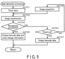
- FIG. 5 is a flowchart showing a specific procedure of the seal detection processing.
- the processor 11 Upon entering the seal detection processing, the processor 11 starts the timer 14 as ACT21. As ACT22, the processor 11 transmits data of an image in which the flag seal 54 is detected to the image recognition server 30 through the communication interface 15 by the function of the transmission unit 114.
- the processor 21 of the image recognition server 30 Upon receiving image data through the communication interface 34 by the function of the reception unit 311, the processor 21 of the image recognition server 30 recognizes price change information displayed on the price change label 53 from an image of that image data by the function of the recognition unit 312. Upon recognizing the price change information, the processor 21 then transmits a response command of recognition success to the scanner 10 of the image data transmission source through the communication interface 34 by the function of the transmission unit 313. The recognized and obtained price change information is included in the response command of recognition success.
- the processor 11 of the scanner 10 to which the image data has been transmitted confirms whether or not the response command of recognition success has been received from the image recognition server 30 by the function of the reception unit 115 as ACT23. If the response command has not been received, the processor 11 determines NO in ACT23 and proceeds to ACT24. The processor 11 confirms whether or not the timer 14 has timed out as ACT24. If the timer 14 has not timed out, the processor 11 determines NO in ACT24 and proceeds to ACT25.
- the processor 11 acquires a next image from the image memory as ACT25. Then, the processor 11 returns to ACT22. That is, the processor 11 transmits the image data to the image recognition server 30. Then, the processor 11 confirms whether or not the response command of recognition success has been received. If the response command of recognition success is not received and the timer 14 has not timed out, the processor 11 acquires the next image from the image memory. Then, the processor 11 repeats the processes of ACT22 and the subsequent steps in the same manner as described above.
- the processor 11 Upon receiving, by the function of the reception unit 115, the response command of recognition success from the image recognition server 30 through the communication interface 15 as a result of transmitting the image data to the image recognition server 30, the processor 11 determines YES in ACT23 and proceeds to ACT26. As ACT 26, the processor 11 outputs, by the function of the output unit 116, the bar code data read by the process of ACT4 and price change information included in the response command of recognition success to the POS terminal 20 through the terminal interface 17.
- the processor 11 determines YES in ACT24 and proceeds to ACT27.
- the processor 11 outputs the bar code data read by the process of ACT4 to the POS terminal 20 through the terminal interface 17 by the function of the output unit 116.
- the processor 11 Upon completion of the process of ACT26 or ACT27, the processor 11 ends the seal detection processing. The processor 11 proceeds to the above-described ACT10 process.
- the imaging device 16 of the scanner 10 is activated.
- an operator picks up the products to be purchased by the customer one by one and holds a surface to which a bar code label 52 is affixed over the reading window of the imaging device 16.
- the operator may be a store clerk or may be the customer.
- a bar code 51 printed on that bar code label 52 is read in the scanner 10.
- the scanner 10 it is determined whether or not a flag seal 54 is attached in the vicinity of the bar code label 52. If the flag seal 54 is not attached, that is, if a bar code 51 of a product which is not a price change target is read, data of that bar code 51 is output from the scanner 10 to the POS terminal 20. As a result, in the POS terminal 20, product sales data is registered at a price obtained from the data of the bar code 51.
- the flag seal 54 is attached, that is, if the bar code 51 of the price change target product is read, the image captured by the imaging device 16 is transmitted from the scanner 10 to the image recognition server 30.
- price change information displayed on the price change label 53 is recognized from that image.
- the price change information of the price change label 53 is output from the scanner 10 to the POS terminal 20 together with the data of the bar code 51.
- product sales data is registered at a price obtained by changing the price obtained from the data of the bar code 51 using the price change information.
- the process of reading the bar code 51 from the image captured by the imaging device 16 is performed by the scanner 10, and the process of recognizing the price change information displayed on the price change label 53 is performed by the image recognition server 30.
- the image transmitted from the scanner 10 to the image recognition server 30 via the communication network 40 is an image captured by the imaging device 16 from when the flag seal 54 is detected to when the price change information is recognized. There is a high likelihood that the image in which the flag seal 54 is detected will include the image of the price change label 53.
- the recognition processing of the price change information displayed on the price change label 53 is performed by the image recognition server 30. Therefore, even if a format of the price change label 53 is changed, it is only necessary to add a new image recognition algorithm corresponding to the changed format to the image recognition server 30. Therefore, there is an advantage wherein it is possible to easily cope with the format change of the price change label 53 regardless of the number of the scanners 10.
- FIGS. 1, 2 , and 4 described in the first embodiment are used in common in the second embodiment. Therefore, descriptions thereof are omitted.
- FIG. 6 is a block diagram showing a main circuit configuration of the scanner 10 and the image recognition server 30 in the second embodiment.
- portions common to those in FIG. 3 showing the same block diagram of the first embodiment are denoted by the same reference numerals.
- the second embodiment is different from the first embodiment in that the processor 11 of the scanner 10 has a function as the recognition unit 117.
- the recognition unit 117 is a function of recognizing price change information displayed on a price change label 53 from an image of a product. As a technique for recognizing the price change information from the image, an existing technique is used.
- the recognition unit 117 can also be called a device-side recognition unit.
- FIG. 7 is a flowchart showing a specific procedure of seal detection processing.
- the part of the seal detection processing that is indicated by ACT9 in FIG. 4 is different from that in the first embodiment.
- the processor 11 when entering the seal detection processing, the processor 11 starts the timer 14 as ACT31. Then, as ACT 32, the processor 11 transmits, by the function of the transmission unit 114, the data of the image in which the flag seal 54 is detected to the image recognition server 30 through the communication interface 15. Further, as ACT33, the processor 11 recognizes, by the function of the recognition unit 117, the price change information displayed on the price change label 53 from the image in which the flag seal 54 is detected.
- the processor 21 of the image recognition server 30 upon receiving the image data through the communication interface 34 by the function of the reception unit 311, the processor 21 of the image recognition server 30 recognizes the price change information displayed on the price change label 53 from the image of that image data by the function of the recognition unit 312. Upon recognizing the price change information, the processor 21 then transmits, by the function of the transmission unit 313, a response command of recognition success to the scanner 10 of the image data transmission source through the communication interface 34.
- the response command of recognition success includes the recognized price change information.
- the processor 11 that has finished the processes of ACT32 and ACT33 confirms whether or not the recognition of the price change information has succeeded as ACT34. If the recognition is not successful, the processor 11 determines NO in ACT34 and proceeds to ACT35. The processor 11 confirms whether or not the timer 14 has timed out as ACT35. If the timer 14 has not timed out, the processor 11 determines NO in ACT35 and proceeds to ACT36.
- the processor 11 acquires a next image from the image memory as ACT36. Then, the processor 11 returns to ACT32. That is, the processor 11 transmits the image data to the image recognition server 30. Further, the processor 11 recognizes the price change information displayed on the price change label 53 from that image. Then, the processor 11 confirms whether or not the recognition of the price change information has succeeded. If the recognition of the price change information is not successful and the timer 14 has not timed out, the processor 11 acquires the next image from the image memory. Then, the processor 11 repeats the processes of ACT32 and the subsequent steps in the same manner as described above.
- the processor 11 determines YES in ACT34 and proceeds to ACT37. As ACT37, the processor 11 outputs the bar code data read in the process of ACT4 and the price change information which is successfully recognized to the POS terminal 20 through the terminal interface 17 by the function of the output unit 116.
- the processor 11 determines YES in ACT35 and proceeds to ACT38.
- the processor 11 outputs the bar code data read by the process of ACT4 to the POS terminal 20 through the terminal interface 17 by the function of the output unit 116.
- the processor 11 Upon completion of the process of ACT37 or ACT38, the processor 11 ends the seal detection processing. The processor 11 proceeds to the process of ACT10 in FIG. 4 .
- the scanner 10 upon detection of the flag seal 54 by the function of the determination unit 113 from the image of the product of which the bar code 51 is read by the function of the reading unit 112, the scanner 10 transmits the image to the image recognition server 30 by the function of the transmission unit 114. Further, the scanner 10 recognizes the price change information displayed on the price change label 53 from that image by the function of the recognition unit 117.
- the scanner 10 If the price change information is recognized by the function of the recognition unit 117, the scanner 10 outputs the data of the bar code 51 and the price change information to the POS terminal 20 by the function of the output unit 116. Even in a case where the recognition unit 117 cannot recognize the price change information, if the price change information recognized by the image recognition server 30 is received by the function of the reception unit 115, the data of the bar code 51 and the price change information are output to the POS terminal 20 by the function of the output unit 116.
- the product sales data is registered at the price obtained by changing the price obtained from the data of the bar code 51 using the price change information.
- the image in which the flag seal 54 is detected will include the image of the price change label 53. Therefore, if the format of the price change label 53 corresponds to an image recognition algorithm prepared by the scanner 10, there is a high likelihood that the price change information will first be recognized by the recognition unit 117. That is, since it is not necessary to wait until the price change information is recognized in the image recognition server 30, it is possible to increase the processing efficiency of the product registration. In addition, in a case where the price change information is first recognized by the recognition unit 117 before the timer 14 times out, since the subsequent image is not transmitted to the image recognition server 30, there is an advantage in that the data communication amount of the communication network 40 can be reduced compared to the first embodiment.
- the price change information can be surely recognized by preparing that algorithm by the image recognition server 30. Therefore, it is possible to cope with the format change of the price change label 53 without changing the algorithm on the scanner 10 side.
- FIGS. 1, 2 , and 4 described in the first embodiment and FIG. 6 described in the second embodiment are used in common in the third embodiment. Thus, descriptions thereof are omitted.
- FIG. 8 is a flowchart showing a specific procedure of the seal detection processing. Also in the third embodiment, a part of the seal detection processing that is indicated by ACT9 in FIG. 4 is different from that in the first or second embodiment.
- the processor 11 upon entering the seal detection processing, recognizes the price change information displayed on the price change label 53 from the image in which the flag seal 54 is detected by the function of the recognition unit 117 as ACT41. Normally, there is a high likelihood that the image in which the flag seal 54 is detected will include the image of the price change label 53. Therefore, if the format of the price change label 53 corresponds to an image recognition algorithm prepared by the scanner 10, there is a high likelihood that the price change information will be recognized from that image by the recognition unit 117.
- the processor 11 confirms whether or not the recognition of the price change information has succeeded as ACT42. If the recognition of the price change information is successful, the processor 11 determines YES in ACT42 and proceeds to ACT48. As ACT48, the processor 11 outputs, by the function of the output unit 116, the bar code data read in the process of ACT4 and the price change information which has successfully been recognized to the POS terminal 20 through the terminal interface 17. The processor 11 ends the seal detection processing and proceeds to the process of ACT10 in FIG. 4 .
- the recognition unit 117 cannot recognize the price change information from that image.
- the processor 11 determines NO in ACT42, and proceeds to ACT43. Thereafter, the processor 11 performs, as ACT43 to ACT49, the same processes as ACT22 to ACT27 described in the first embodiment.
- the scanner 10 recognizes the price change information displayed on the price change label 53 from that image by the function of the recognition unit 117. If the price change information is recognized, the scanner 10 outputs the data of the bar code 51 and the price change information to the POS terminal 20 by the function of the output unit 116.
- the scanner 10 transmits the image to the image recognition server 30 by the function of the transmission unit 114.
- the scanner 10 Upon receiving the price change information recognized by the image recognition server 30 by the function of the reception unit 115, the scanner 10 outputs the data of the bar code 51 and the price change information to the POS terminal 20 by the function of the output unit 116.
- the product sales data is registered at a price obtained by changing the price obtained from the data of the bar code 51 using the price change information.
- the image in which the flag seal 54 is detected will include the image of the price change label 53. Therefore, in the case where the format of the price change label 53 corresponds to the image recognition algorithm prepared by the scanner 10, the frequency of transmission of an image from the scanner 10 to the image recognition server 30 is significantly reduced as compared with the first or second embodiment. As a result, there is an advantage wherein the data communication amount of the communication network 40 can be reduced more than in the first or second embodiment. Further, needless to say it is possible to cope with the format change of the price change label 53 without changing the algorithm on the scanner 10 side.
- a device in which the scanner 10 and the POS terminal 20 are integrated for example, a self-checkout terminal, may be an aspect of the code reading device.
- the scanner 10 may include devices such as a keyboard, a touch panel, and a display, and may support registration of merchandise such as fresh food to which a bar code is not affixed.
- an image acquired by the acquisition unit 111 is transmitted to the image recognition server 30 by the function of the transmission unit 114. If the price change information recognized by the image recognition server 30 is received by the function of the reception unit 115, the price change information is output to the POS terminal 20 together with the code of the product to which the bar code is not affixed by the function of the output unit 116. Even if such a configuration is adopted, it is possible to reduce the data communication amount of the communication network 40, and to easily cope with the format change of the price change label 53.
- the image recognized by the image recognition server 30 is not limited to the price change information displayed on the price change label 53.
- a label on which an expiration date is displayed is affixed to a product and a discount rate is changed depending on a length of a remaining period until the expiration date.
- the image recognized by the image recognition server 30 is information of the expiration date displayed on the label.
- the information of the expiration date is also information for changing the price as a result, it can also be called the price change information.
- the program according to the present embodiment may be transferred in a state of being stored in an electronic device, or may be transferred in a state of not being stored in an electronic device. In the latter case, the program may be transferred via a network, or may be transferred in a state of being recorded in a recording medium.
- the recording medium is a non-transitory tangible medium.
- the recording medium is a computer-readable medium.
- the recording medium may be any medium as long as it can store a program such as a CD-ROM or a memory card and can be read by a computer, and its form is not limited.
Landscapes
- Physics & Mathematics (AREA)
- Engineering & Computer Science (AREA)
- General Physics & Mathematics (AREA)
- Business, Economics & Management (AREA)
- Theoretical Computer Science (AREA)
- Accounting & Taxation (AREA)
- Toxicology (AREA)
- Health & Medical Sciences (AREA)
- Electromagnetism (AREA)
- General Health & Medical Sciences (AREA)
- Artificial Intelligence (AREA)
- Computer Vision & Pattern Recognition (AREA)
- Finance (AREA)
- General Business, Economics & Management (AREA)
- Strategic Management (AREA)
- General Engineering & Computer Science (AREA)
- Cash Registers Or Receiving Machines (AREA)
Abstract
Description
- Embodiments described herein relate generally to a code reading device, a program recording medium, a code reading system, and a code reading method.
- There is a code reading device that reads a bar code affixed to a product from an image of the product captured by an imaging device and outputs bar code data to a processing device of product sales data. In addition, there is also known a code reading device that, when it is detected from an image of a product on which a label displaying price change information related to a change in price is affixed, recognizes the price change information displayed on the label, and outputs the price change information to a processing device together with bar code data. With such a code reading device, an operator holds the product over a reading window of the imaging device so that the bar code and the label affixed to the product are captured. As a result, in the processing device, the product sales data is processed at the changed price.
- However, the code reading device recognizes the price change information displayed on the label created in a predetermined format, but does not recognize price change information displayed on a label created in a format different from the predetermined format. Thus, in a case of changing the format of the label, it is necessary to change an algorithm of image recognition provided in the code reading device.
- In recent years, with improvements in image recognition technology, an image recognition server capable of recognizing information from various images has been developed. Therefore, it is being considered to connect such an image recognition server to the code reading device and to entrust the image recognition of the label to the image recognition server, so that it is not necessary to change the algorithm of the image recognition provided in the code reading device. However, in such a method, it is necessary to transmit the image of the product captured by the imaging device from the code reading device to the image recognition server regardless of whether or not the label is affixed to the product. Thus, a data communication amount of the communication network connecting the code reading device and the image recognition server becomes enormous. In addition, since the product to be labeled is considered to be a small part, there is a concern that most data communication is wasted.
- Patent Literature 1:
Japanese Patent Application KOKAI Publication No. 2019-091501 - An object to be achieved by an embodiment of the present invention is to provide a technique for reducing a data communication amount of a communication network by suppressing useless data communication between a code reading device and an image recognition server which are connected via a communication network.
-
-
FIG. 1 is an overall configuration diagram of a code reading system according to an embodiment. -
FIG. 2 is a schematic diagram showing an example of a product according to the embodiment. -
FIG. 3 is a block diagram showing a main circuit configuration of a scanner and an image recognition server in a first embodiment. -
FIG. 4 is a flowchart showing a procedure of main information processing performed by a processor of the scanner according to a code reading program. -
FIG. 5 is a flowchart showing a specific procedure of seal detection processing inFIG. 4 in the first embodiment. -
FIG. 6 is a block diagram showing a main circuit configuration of a scanner and an image recognition server in a second embodiment. -
FIG. 7 is a flowchart showing a specific procedure of the seal detection processing inFIG. 4 in the second embodiment. -
FIG. 8 is a flowchart showing a specific procedure of the seal detection processing inFIG. 4 in a third embodiment. - In an embodiment, a code reading device includes an acquisition unit, a reading unit, a determination unit, a transmission unit, a reception unit, and an output unit. The acquisition unit is configured to acquire an image of a product captured by an imaging device. The reading unit is configured to read a code for obtaining a price of the product from the image of the product acquired by the acquisition unit. The determination unit is configured to determine whether or not a label displaying price change information related to a change in the price obtained by the code is affixed to the product. The transmission unit is configured to transmit the image of the product to an image recognition server for recognizing the price change information displayed on the label if the determination unit determines that the label is affixed to the product. The reception unit is configured to receive the price change information recognized by the image recognition server. The output unit is configured to output the code read by the reading unit to a processing device that processes sales data of the product if it is determined that the label is not affixed to the product. The output unit is configured to output the code read by the reading unit and the price change information received by the reception unit to the processing device if it is determined that the label is affixed to the product.
- Hereinafter, some embodiments will be described with reference to the drawings.
- First, a first embodiment will be described with reference to
FIGS. 1 to 5 . -
FIG. 1 is an overall configuration diagram of acode reading system 100 according to an embodiment. Thecode reading system 100 includes a plurality ofscanners 10, a plurality of POS (point of sale)terminals 20, and animage recognition server 30. The plurality ofscanners 10 andPOS terminals 20 correspond to each other on a one-to-one basis, and are connected to each other by communication cables. The plurality ofscanners 10 and theimage recognition server 30 are connected to acommunication network 40. Thecommunication network 40 is typically a local area network (LAN). The LAN may be a wired LAN or a wireless LAN. Thecommunication network 40 may be, for example, the Internet, and theimage recognition server 30 may be a cloud computing server. - The
scanner 10 is an example of a code reading device that reads a bar code from an image of a product captured by an imaging device. The bar code is a bar code of a product code uniquely set for each product in order to identify each product, and is usually affixed to a case, a package, or the like of the product. Thescanner 10 outputs data of the read bar code to thePOS terminal 20. Thescanner 10 may read a code such as a two-dimensional data code or a character code instead of the bar code. - The
POS terminal 20 acquires a product code from the data of the bar code read by thescanner 10. ThePOS terminal 20 acquires a price set in a price master in association with the product code, and registers sales data of that product based on that price. That is, the bar code is a code for obtaining the price of the product. ThePOS terminal 20 is an example of a processing device that processes product sales data. Since such aPOS terminal 20 is well known, a detailed description thereof will be omitted. -
FIG. 2 is a schematic diagram showing an example of aproduct 50 according to the present embodiment. Theproduct 50 is a price change target product that is sold at a discount of 10% from a normal price. As shown inFIG. 2 , abar code label 52 displaying abar code 51 together with a product name and the normal price is affixed to a case or a package of theproduct 50. Thebar code label 52 may be printed on the case or the package, or may be attached to the case or the package as a seal-like label. Aprice change label 53 and aflag seal 54 are affixed to the same surface of theproduct 50 as thebar code label 52. Theprice change label 53 is attached to the case or the package as a seal-like label. The same applies to theflag seal 54. - The
price change label 53 is a label displaying price change information related to a change in price. Theprice change label 53 inFIG. 2 displays price change information for discounting the price at a rate of 10%. The price change information is not limited to the information on the discount rate. For example, the price change information may be information on a discount amount for discounting the price, selling price information for changing the price to a predetermined selling price, information on an extra rate for increasing the price, or the like. - The
flag seal 54 indicates that theprice change label 53 is affixed to theproduct 50, and is attached to theproduct 50 as a pair with theprice change label 53. As shown inFIG. 2 , at least a part of theflag seal 54 is attached to overlap thebar code label 52. Theflag seal 54 may not necessarily be attached over thebar code label 52. Theflag seal 54 may be attached so as to be in contact with an edge of thebar code label 52, for example. In short, theflag seal 54 may be attached in the vicinity of thebar code label 52. On the other hand, theprice change label 53 may not necessarily be attached in the vicinity of thebar code label 52. In this connection, theflag seal 54 is not affixed to a product which is not a price change target. Basically, only thebar code label 52 is affixed to the product which is not a price change target. -
FIG. 3 is a block diagram showing a main circuit configuration of thescanner 10 and theimage recognition server 30. InFIG. 3 , only onescanner 10 is shown. Since theother scanners 10 have the same configuration, descriptions thereof will be omitted. - The
scanner 10 includes aprocessor 11, amain memory 12, anauxiliary storage device 13, atimer 14, acommunication interface 15, animaging device 16, and aterminal interface 17. Theprocessor 11, themain memory 12, theauxiliary storage device 13, thetimer 14, thecommunication interface 15, theimaging device 16, and theterminal interface 17 are connected by asystem transmission line 18. Thesystem transmission line 18 includes an address bus, a data bus, a control signal line, etc. Thescanner 10 forms a computer by connecting theprocessor 11, themain memory 12, theauxiliary storage device 13, and thetimer 14 via thesystem transmission line 18. By connecting thecommunication interface 15, theimaging device 16, and theterminal interface 17 to this computer, a function as thescanner 10 is realized. - The
processor 11 corresponds to a central part of the above computer. Theprocessor 11 controls each unit to realize various functions as thescanner 10 according to an operating system or an application program. Theprocessor 11 may be processing circuitry such as a central processing unit (CPU), a graphics processing unit (GPU), an application specific integrated circuit (ASIC), or a programmable logic device (for example, a simple programmable logic device (SPLD), a complex programmable logic device (CPLD), or a field programmable gate array (FPGA)). Theprocessor 11 is not limited to a case in which it is formed as a single processing circuit, and a plurality of processing circuits may be combined into theprocessor 11. The same applies to the other processors according to the present embodiment. - The
main memory 12 may be a volatile memory (random access memory) or a non-volatile memory (read-only memory, non-volatile random access memory). Themain memory 12 stores an information processing program and data necessary for information processing. Theprocessor 11 realizes a predetermined function by reading and executing a program stored in themain memory 12. Instead of storing a program in themain memory 12, the program may be directly embedded in theprocessor 11. In this case, theprocessor 11 realizes a predetermined function by reading and executing a program embedded inside. Further, the predetermined function may be realized not only by theprocessor 11 executing a program, but also by a combination of logic circuits. The same applies to the other main memories according to the present embodiment. - The
auxiliary storage device 13 corresponds to an auxiliary storage portion of the above computer. As theauxiliary storage device 13, for example, a well-known storage device such as a solid-state drive (SSD), a hard disc drive (HDD), or an electrically erasable programmable read-only memory (EEPROM) (registered trademark) is used alone or in combination of a plurality of storage devices. Theauxiliary storage device 13 stores data used when theprocessor 11 performs various types of processing, data created by processing in theprocessor 11, or the like. Theauxiliary storage device 13 may store the information processing program described above. - The information processing program stored in the
main memory 12 or theauxiliary storage device 13 includes a code reading program. A method of installing the code reading program in themain memory 12 or theauxiliary storage device 13 is not particularly limited. The code reading program can be installed in themain memory 12 or theauxiliary storage device 13 by recording a control program in a removable recording medium or by distributing the code reading program through communication via a network. The recording medium may be in any form as long as it can store a program and can be read by the device, such as an SD memory card or a USB memory. - The
timer 14 is a device that starts counting time in response to an activation signal and outputs a timeout signal when the counted time reaches a predetermined timeout time. In the present embodiment, the timeout time is an operation time required for theimage recognition server 30 to recognize the price change information displayed on theprice change label 53 from the image of the product. - The
communication interface 15 is an interface with theimage recognition server 30. Thecommunication interface 15 transmits and receives data signals to and from theimage recognition server 30 connected via thecommunication network 40 according to a predetermined communication protocol. - The
imaging device 16 has a charge coupled device (CCD) image pickup element which is an area image sensor, a drive circuit for driving this CCD image pickup element, and an image pickup lens for forming an image in an image pickup area through a reading window on the CCD image pickup element, and outputs data of the image formed on the CCD image pickup element. - The
terminal interface 17 is an interface with thePOS terminal 20. Theterminal interface 17 transmits and receives data signals to and from thePOS terminal 20 connected by a communication cable. - The
processor 11 has functions as anacquisition unit 111, areading unit 112, adetermination unit 113, atransmission unit 114, areception unit 115, and anoutput unit 116. Theacquisition unit 111 is a function of acquiring an image of a product captured by theimaging device 16. Theacquisition unit 111 can also be called an acquisition means. - The
reading unit 112 is a function of reading a code for obtaining a price of the product, that is, thebar code 51, from the image of the product acquired by theacquisition unit 111. As a technique for reading thebar code 51 from the image, an existing technique is used. Thereading unit 112 can also be called a reading means. - The
determination unit 113 has a function of determining whether or not a label displaying price change information related to a change in price obtained from thebar code 51, that is, theprice change label 53, is affixed to the product. If theflag seal 54 affixed in the vicinity of thebar code 51 is detected, thedetermination unit 113 determines that theprice change label 53 is affixed to the product. If theflag seal 54 is not detected, thedetermination unit 113 determines that theprice change label 53 is not affixed to the product. Thedetermination unit 113 can also be called a determination means. - The
transmission unit 114 is a function of transmitting the image of the product captured by theimaging device 16 to theimage recognition server 30 if thedetermination unit 113 determines that theprice change label 53 is affixed to the product. Thetransmission unit 114 can also be called a terminal-side transmission unit or transmission means. - The
reception unit 115 is a function of receiving price change information recognized by theimage recognition server 30. Thereception unit 115 can also be called a terminal-side reception unit or reception means. - The
output unit 116 includes the following two functions. The first function is to output data of thebar code 51 read by thereading unit 112 to thePOS terminal 20 if thedetermination unit 113 determines that theprice change label 53 is not affixed to the product. The second function is to output the data of thebar code 51 read by thereading unit 112 and the price change information received by thereception unit 115 to thePOS terminal 20 if thedetermination unit 113 determines that theprice change label 53 is affixed to the product. Theoutput unit 116 can also be called an output means. - The
image recognition server 30 includes aprocessor 31, amain memory 32, anauxiliary storage device 33, and acommunication interface 34. Theprocessor 31, themain memory 32, theauxiliary storage device 33, and thecommunication interface 34 are connected by asystem transmission line 35. Thesystem transmission line 35 includes an address bus, a data bus, a control signal line, etc. Theimage recognition server 30 forms a computer by connecting theprocessor 31, themain memory 32, and theauxiliary storage device 33 by thesystem transmission line 35. By connecting thecommunication interface 34 to this computer, the function as theimage recognition server 30 is realized. - The
processor 31 corresponds to a central part of the above computer. Theprocessor 31 controls each unit to realize various functions as theimage recognition server 30 according to the information processing program. Theprocessor 31 is, for example, a CPU. - The
main memory 32 is a volatile memory (random access memory) or a nonvolatile memory (read-only memory, nonvolatile random access memory). - The
auxiliary storage device 33 corresponds to an auxiliary storage portion of the above computer. As theauxiliary storage device 33, for example, a well-known storage device such as an SSD, an HDD, or an EEPROM is used alone or in combination of a plurality of storage devices. Theauxiliary storage device 33 stores data used when theprocessor 31 performs various processing, data created by the processing in theprocessor 31, or the like. Theauxiliary storage device 33 may store the application program described above. - The
communication interface 34 is an interface with eachscanner 10. Thecommunication interface 34 transmits and receives data signals to and from eachscanner 10 connected via thecommunication network 40 according to a predetermined communication protocol. - In the
image recognition server 30 having such a configuration, theprocessor 31 has functions as areception unit 311, arecognition unit 312, and atransmission unit 313. Thereception unit 311 has a function of receiving an image of a product sent from thescanner 10 via thecommunication network 40. Thereception unit 311 can also be called a server-side reception unit. - The
recognition unit 312 has a function of recognizing the price change information displayed on theprice change label 53 from the image of the product received by thereception unit 311. As a technique for recognizing the price change information from the image, an existing technique is used. Therecognition unit 312 can also be called a server-side recognition unit. - The
transmission unit 313 has a function of transmitting the price change information recognized by therecognition unit 312 to thescanner 10 which is a transmission source of the recognized image. Thetransmission unit 313 can also be called a server-side transmission unit. -
FIGS. 4 and5 are flowcharts showing a procedure of main information processing performed by theprocessor 11 of thescanner 10 according to a code reading program. That is, theprocessor 11 causes thescanner 10 to function as a code reading device according to the code reading program. A main operation of thescanner 10 will be described below with reference to the flowcharts. Note that the procedure of the information processing is not limited to that according to the flowcharts. As long as similar effects can be obtained, the procedure can be modified as appropriate. - The
processor 11 waits for input of a reading start command as ACT1. The reading start command is given from acorresponding POS terminal 20. For example, upon settlement of a transaction with an immediately preceding customer in thePOS terminal 20, a reading start command is output from thePOS terminal 20 to thescanner 10. If the reading start command is input, theprocessor 11 determines YES in ACT1 and proceeds to ACT2. Theprocessor 11 outputs an activation signal to theimaging device 16 as ACT2. In theimaging device 16 to which the activation signal is input, a CCD image pickup element is in an energized state. Data of an image formed on the CCD image pickup element through the reading window is output to the image memory. The image memory is a part of a volatile memory area in themain memory 12. - The
processor 11 acquires an image stored in the image memory by the function of theacquisition unit 111 as ACT3. Then, theprocessor 11 reads abar code 51 from the image by the function of thereading unit 112 as ACT4. Theprocessor 11 confirms whether or not thebar code 51 has been read as ACT5. If thebar code 51 has not been read from the image, theprocessor 11 determines NO in ACT5 and returns to ACT3. That is, theprocessor 11 sequentially acquires images from the image memory, and repeats a process of reading thebar code 51 from the images. As a result, if thebar code 51 has been read, theprocessor 11 determines YES in ACT5 and proceeds to ACT6. - The
processor 11 determines whether or not aprice change label 53 is affixed to the product by the function of thedetermination unit 113 as ACT6. Specifically, theprocessor 11 searches for aflag seal 54 from the image in which thebar code 51 has been read. Theprocessor 11 confirms whether or not theflag seal 54 has been detected as ACT7. - If the
price change label 53 is not affixed to the product, theflag seal 54 is not detected. If theflag seal 54 cannot be detected, theprocessor 11 determines NO in ACT7 and proceeds to ACT8. Theprocessor 11 outputs data of thebar code 51 to thePOS terminal 20 through theterminal interface 17 by the function of theoutput unit 116 as ACT8. - If the
price change label 53 is affixed to the product, theflag seal 54 is detected in principle. If theflag seal 54 can be detected, theprocessor 11 determines YES in ACT7 and proceeds to ACT9. Theprocessor 11 performs seal detection processing as ACT9. The seal detection processing will be described later. - If the
processor 11 ends the process of ACT8 or ACT9, theprocessor 11 proceeds to ACT10. Theprocessor 11 confirms whether or not a reading end command is input as ACT10. The reading end command is given from thecorresponding POS terminal 20. For example, upon a closing operation for instructing an end of registration of a product to be purchased by the customer in thePOS terminal 20, the reading end command is output from thePOS terminal 20 to thescanner 10. If the reading end command is not input, theprocessor 11 determines NO in ACT10 and returns to ACT3. Theprocessor 11 executes the processes of ACT3 and the subsequent steps in the same manner as described above. - Upon input of the reading end command, the
processor 11 determines YES in ACT10 and proceeds to ACT11. Theprocessor 11 outputs a stop signal to theimaging device 16 as ACT11. In theimaging device 16 to which the stop signal is input, the CCD image pickup element is in a non-energized state. Thus, theprocessor 11 ends the information processing of the procedure shown in the flowchart ofFIG. 4 . Theprocessor 11 again waits for a reading start command to be input. -
FIG. 5 is a flowchart showing a specific procedure of the seal detection processing. Upon entering the seal detection processing, theprocessor 11 starts thetimer 14 as ACT21. As ACT22, theprocessor 11 transmits data of an image in which theflag seal 54 is detected to theimage recognition server 30 through thecommunication interface 15 by the function of thetransmission unit 114. - Upon receiving image data through the
communication interface 34 by the function of thereception unit 311, the processor 21 of theimage recognition server 30 recognizes price change information displayed on theprice change label 53 from an image of that image data by the function of therecognition unit 312. Upon recognizing the price change information, the processor 21 then transmits a response command of recognition success to thescanner 10 of the image data transmission source through thecommunication interface 34 by the function of thetransmission unit 313. The recognized and obtained price change information is included in the response command of recognition success. - The
processor 11 of thescanner 10 to which the image data has been transmitted confirms whether or not the response command of recognition success has been received from theimage recognition server 30 by the function of thereception unit 115 as ACT23. If the response command has not been received, theprocessor 11 determines NO in ACT23 and proceeds to ACT24. Theprocessor 11 confirms whether or not thetimer 14 has timed out as ACT24. If thetimer 14 has not timed out, theprocessor 11 determines NO in ACT24 and proceeds to ACT25. - The
processor 11 acquires a next image from the image memory as ACT25. Then, theprocessor 11 returns to ACT22. That is, theprocessor 11 transmits the image data to theimage recognition server 30. Then, theprocessor 11 confirms whether or not the response command of recognition success has been received. If the response command of recognition success is not received and thetimer 14 has not timed out, theprocessor 11 acquires the next image from the image memory. Then, theprocessor 11 repeats the processes of ACT22 and the subsequent steps in the same manner as described above. - Upon receiving, by the function of the
reception unit 115, the response command of recognition success from theimage recognition server 30 through thecommunication interface 15 as a result of transmitting the image data to theimage recognition server 30, theprocessor 11 determines YES in ACT23 and proceeds to ACT26. As ACT 26, theprocessor 11 outputs, by the function of theoutput unit 116, the bar code data read by the process of ACT4 and price change information included in the response command of recognition success to thePOS terminal 20 through theterminal interface 17. - On the other hand, if the
timer 14 times out without receiving the response command of recognition success from theimage recognition server 30, theprocessor 11 determines YES in ACT24 and proceeds to ACT27. As ACT27, theprocessor 11 outputs the bar code data read by the process of ACT4 to thePOS terminal 20 through theterminal interface 17 by the function of theoutput unit 116. - Upon completion of the process of ACT26 or ACT27, the
processor 11 ends the seal detection processing. Theprocessor 11 proceeds to the above-described ACT10 process. - In the
code reading system 100 including thescanner 10 and theimage recognition server 30 that operate as described above, the following working effects can be achieved. First, upon a reading start command being given from thePOS terminal 20 to thescanner 10 prior to registration of a first item of products to be purchased by a customer, theimaging device 16 of thescanner 10 is activated. In this state, an operator picks up the products to be purchased by the customer one by one and holds a surface to which abar code label 52 is affixed over the reading window of theimaging device 16. The operator may be a store clerk or may be the customer. - Upon the surface to which the
bar code label 52 is affixed being held over the reading window, abar code 51 printed on thatbar code label 52 is read in thescanner 10. In thescanner 10, it is determined whether or not aflag seal 54 is attached in the vicinity of thebar code label 52. If theflag seal 54 is not attached, that is, if abar code 51 of a product which is not a price change target is read, data of thatbar code 51 is output from thescanner 10 to thePOS terminal 20. As a result, in thePOS terminal 20, product sales data is registered at a price obtained from the data of thebar code 51. - On the other hand, if the
flag seal 54 is attached, that is, if thebar code 51 of the price change target product is read, the image captured by theimaging device 16 is transmitted from thescanner 10 to theimage recognition server 30. In theimage recognition server 30, price change information displayed on theprice change label 53 is recognized from that image. Upon recognition of the price change information, the price change information of theprice change label 53 is output from thescanner 10 to thePOS terminal 20 together with the data of thebar code 51. As a result, in thePOS terminal 20, product sales data is registered at a price obtained by changing the price obtained from the data of thebar code 51 using the price change information. - As described above, in the
code reading system 100, when the price change target product to which theprice change label 53 is affixed together with thebar code label 52 is registered, the process of reading thebar code 51 from the image captured by theimaging device 16 is performed by thescanner 10, and the process of recognizing the price change information displayed on theprice change label 53 is performed by theimage recognition server 30. In this case, the image transmitted from thescanner 10 to theimage recognition server 30 via thecommunication network 40 is an image captured by theimaging device 16 from when theflag seal 54 is detected to when the price change information is recognized. There is a high likelihood that the image in which theflag seal 54 is detected will include the image of theprice change label 53. Therefore, it is possible to prevent a useless image which is not related to the recognition of the price change information from being transmitted from thescanner 10 to theimage recognition server 30. As a result, even when a plurality ofscanners 10 are connected to thecommunication network 40, the data communication amount of thecommunication network 40 can be reduced. - Even if the
image recognition server 30 fails to recognize the price change information, the transmission of the image ends when the timeout time of thetimer 14 elapses after theflag seal 54 is detected. Therefore, also from this point of view, there is an effect wherein useless image transmission can be suppressed. - In the
code reading system 100, the recognition processing of the price change information displayed on theprice change label 53 is performed by theimage recognition server 30. Therefore, even if a format of theprice change label 53 is changed, it is only necessary to add a new image recognition algorithm corresponding to the changed format to theimage recognition server 30. Therefore, there is an advantage wherein it is possible to easily cope with the format change of theprice change label 53 regardless of the number of thescanners 10. - Next, a second embodiment will be described with reference to
FIGS. 6 and7 . Note thatFIGS. 1, 2 , and4 described in the first embodiment are used in common in the second embodiment. Therefore, descriptions thereof are omitted. -
FIG. 6 is a block diagram showing a main circuit configuration of thescanner 10 and theimage recognition server 30 in the second embodiment. InFIG. 6 , portions common to those inFIG. 3 showing the same block diagram of the first embodiment are denoted by the same reference numerals. As is apparent from a comparison betweenFIGS. 6 and3 , the second embodiment is different from the first embodiment in that theprocessor 11 of thescanner 10 has a function as therecognition unit 117. - The
recognition unit 117 is a function of recognizing price change information displayed on aprice change label 53 from an image of a product. As a technique for recognizing the price change information from the image, an existing technique is used. Therecognition unit 117 can also be called a device-side recognition unit. -
FIG. 7 is a flowchart showing a specific procedure of seal detection processing. In the second embodiment, the part of the seal detection processing that is indicated by ACT9 inFIG. 4 is different from that in the first embodiment. - In the second embodiment, when entering the seal detection processing, the
processor 11 starts thetimer 14 as ACT31. Then, asACT 32, theprocessor 11 transmits, by the function of thetransmission unit 114, the data of the image in which theflag seal 54 is detected to theimage recognition server 30 through thecommunication interface 15. Further, as ACT33, theprocessor 11 recognizes, by the function of therecognition unit 117, the price change information displayed on theprice change label 53 from the image in which theflag seal 54 is detected. - Also in the second embodiment, upon receiving the image data through the
communication interface 34 by the function of thereception unit 311, the processor 21 of theimage recognition server 30 recognizes the price change information displayed on theprice change label 53 from the image of that image data by the function of therecognition unit 312. Upon recognizing the price change information, the processor 21 then transmits, by the function of thetransmission unit 313, a response command of recognition success to thescanner 10 of the image data transmission source through thecommunication interface 34. The response command of recognition success includes the recognized price change information. - The
processor 11 that has finished the processes of ACT32 and ACT33 confirms whether or not the recognition of the price change information has succeeded as ACT34. If the recognition is not successful, theprocessor 11 determines NO in ACT34 and proceeds to ACT35. Theprocessor 11 confirms whether or not thetimer 14 has timed out as ACT35. If thetimer 14 has not timed out, theprocessor 11 determines NO in ACT35 and proceeds to ACT36. - The
processor 11 acquires a next image from the image memory as ACT36. Then, theprocessor 11 returns to ACT32. That is, theprocessor 11 transmits the image data to theimage recognition server 30. Further, theprocessor 11 recognizes the price change information displayed on theprice change label 53 from that image. Then, theprocessor 11 confirms whether or not the recognition of the price change information has succeeded. If the recognition of the price change information is not successful and thetimer 14 has not timed out, theprocessor 11 acquires the next image from the image memory. Then, theprocessor 11 repeats the processes of ACT32 and the subsequent steps in the same manner as described above. - If the price change information is successfully recognized by the function of the
recognition unit 117 or the response command of recognition success is received from theimage recognition server 30 by the function of thereception unit 115, theprocessor 11 determines YES in ACT34 and proceeds to ACT37. As ACT37, theprocessor 11 outputs the bar code data read in the process of ACT4 and the price change information which is successfully recognized to thePOS terminal 20 through theterminal interface 17 by the function of theoutput unit 116. - On the other hand, in a case where the
recognition unit 117 cannot recognize the price change information and thetimer 14 times out without receiving the response command of recognition success from theimage recognition server 30, theprocessor 11 determines YES in ACT35 and proceeds to ACT38. As ACT38, theprocessor 11 outputs the bar code data read by the process of ACT4 to thePOS terminal 20 through theterminal interface 17 by the function of theoutput unit 116. - Upon completion of the process of ACT37 or ACT38, the
processor 11 ends the seal detection processing. Theprocessor 11 proceeds to the process of ACT10 inFIG. 4 . - As described above, in the second embodiment, upon detection of the
flag seal 54 by the function of thedetermination unit 113 from the image of the product of which thebar code 51 is read by the function of thereading unit 112, thescanner 10 transmits the image to theimage recognition server 30 by the function of thetransmission unit 114. Further, thescanner 10 recognizes the price change information displayed on theprice change label 53 from that image by the function of therecognition unit 117. - If the price change information is recognized by the function of the
recognition unit 117, thescanner 10 outputs the data of thebar code 51 and the price change information to thePOS terminal 20 by the function of theoutput unit 116. Even in a case where therecognition unit 117 cannot recognize the price change information, if the price change information recognized by theimage recognition server 30 is received by the function of thereception unit 115, the data of thebar code 51 and the price change information are output to thePOS terminal 20 by the function of theoutput unit 116.
Therefore, in thePOS terminal 20, not only in a case where the price change information is recognized by therecognition unit 312 of theimage recognition server 30 but also in a case where the price change information is recognized by therecognition unit 117 of thescanner 10, the product sales data is registered at the price obtained by changing the price obtained from the data of thebar code 51 using the price change information. - Normally, there is a high likelihood that the image in which the
flag seal 54 is detected will include the image of theprice change label 53. Therefore, if the format of theprice change label 53 corresponds to an image recognition algorithm prepared by thescanner 10, there is a high likelihood that the price change information will first be recognized by therecognition unit 117. That is, since it is not necessary to wait until the price change information is recognized in theimage recognition server 30, it is possible to increase the processing efficiency of the product registration. In addition, in a case where the price change information is first recognized by therecognition unit 117 before thetimer 14 times out, since the subsequent image is not transmitted to theimage recognition server 30, there is an advantage in that the data communication amount of thecommunication network 40 can be reduced compared to the first embodiment. - Even if the format of the
price change label 53 does not correspond to the image recognition algorithm prepared by thescanner 10, the price change information can be surely recognized by preparing that algorithm by theimage recognition server 30. Therefore, it is possible to cope with the format change of theprice change label 53 without changing the algorithm on thescanner 10 side. - Next, a third embodiment will be described with reference to
FIG. 8 . Incidentally,FIGS. 1, 2 , and4 described in the first embodiment andFIG. 6 described in the second embodiment are used in common in the third embodiment. Thus, descriptions thereof are omitted. -
FIG. 8 is a flowchart showing a specific procedure of the seal detection processing. Also in the third embodiment, a part of the seal detection processing that is indicated by ACT9 inFIG. 4 is different from that in the first or second embodiment. - In the third embodiment, upon entering the seal detection processing, the
processor 11 recognizes the price change information displayed on theprice change label 53 from the image in which theflag seal 54 is detected by the function of therecognition unit 117 as ACT41. Normally, there is a high likelihood that the image in which theflag seal 54 is detected will include the image of theprice change label 53. Therefore, if the format of theprice change label 53 corresponds to an image recognition algorithm prepared by thescanner 10, there is a high likelihood that the price change information will be recognized from that image by therecognition unit 117. - The
processor 11 confirms whether or not the recognition of the price change information has succeeded as ACT42. If the recognition of the price change information is successful, theprocessor 11 determines YES in ACT42 and proceeds to ACT48. As ACT48, theprocessor 11 outputs, by the function of theoutput unit 116, the bar code data read in the process of ACT4 and the price change information which has successfully been recognized to thePOS terminal 20 through theterminal interface 17. Theprocessor 11 ends the seal detection processing and proceeds to the process of ACT10 inFIG. 4 . - On the other hand, if the image of the
price change label 53 is not included in the image in which theflag seal 54 is detected, or if the format of theprice change label 53 does not correspond to the image recognition algorithm prepared by thescanner 10, therecognition unit 117 cannot recognize the price change information from that image. Theprocessor 11 determines NO in ACT42, and proceeds to ACT43. Thereafter, theprocessor 11 performs, as ACT43 to ACT49, the same processes as ACT22 to ACT27 described in the first embodiment. - In this way, in the third embodiment, if the
flag seal 54 is detected by the function of thedetermination unit 113 from the image of the product of which thebar code 51 is read by the function of thereading unit 112, thescanner 10 recognizes the price change information displayed on theprice change label 53 from that image by the function of therecognition unit 117. If the price change information is recognized, thescanner 10 outputs the data of thebar code 51 and the price change information to thePOS terminal 20 by the function of theoutput unit 116. - On the other hand, if the price change information cannot be recognized, the
scanner 10 transmits the image to theimage recognition server 30 by the function of thetransmission unit 114. Upon receiving the price change information recognized by theimage recognition server 30 by the function of thereception unit 115, thescanner 10 outputs the data of thebar code 51 and the price change information to thePOS terminal 20 by the function of theoutput unit 116. - Therefore, not only if the price change information is recognized by the
recognition unit 117 of thescanner 10 but also if the price change information is not recognized, as long as the price change information is recognized by therecognition unit 312 of theimage recognition server 30, in thePOS terminal 20, the product sales data is registered at a price obtained by changing the price obtained from the data of thebar code 51 using the price change information. - Normally, there is a high likelihood that the image in which the
flag seal 54 is detected will include the image of theprice change label 53. Therefore, in the case where the format of theprice change label 53 corresponds to the image recognition algorithm prepared by thescanner 10, the frequency of transmission of an image from thescanner 10 to theimage recognition server 30 is significantly reduced as compared with the first or second embodiment. As a result, there is an advantage wherein the data communication amount of thecommunication network 40 can be reduced more than in the first or second embodiment. Further, needless to say it is possible to cope with the format change of theprice change label 53 without changing the algorithm on thescanner 10 side. - The first to third embodiments have been described above, but the embodiments are not limited thereto.
- For example, in the above embodiments, the case in which the
scanner 10 and thePOS terminal 20 are connected by a communication cable has been exemplified. As another embodiment, a device in which thescanner 10 and thePOS terminal 20 are integrated, for example, a self-checkout terminal, may be an aspect of the code reading device. - The
scanner 10 may include devices such as a keyboard, a touch panel, and a display, and may support registration of merchandise such as fresh food to which a bar code is not affixed. In this case, for example, when thescanner 10 is instructed by a key operation that theprice change label 53 is affixed to the product by a key operation, an image acquired by theacquisition unit 111 is transmitted to theimage recognition server 30 by the function of thetransmission unit 114. If the price change information recognized by theimage recognition server 30 is received by the function of thereception unit 115, the price change information is output to thePOS terminal 20 together with the code of the product to which the bar code is not affixed by the function of theoutput unit 116. Even if such a configuration is adopted, it is possible to reduce the data communication amount of thecommunication network 40, and to easily cope with the format change of theprice change label 53. - The image recognized by the
image recognition server 30 is not limited to the price change information displayed on theprice change label 53. For example, an operation is conceivable in which a label on which an expiration date is displayed is affixed to a product and a discount rate is changed depending on a length of a remaining period until the expiration date. In this case, the image recognized by theimage recognition server 30 is information of the expiration date displayed on the label. However, since the information of the expiration date is also information for changing the price as a result, it can also be called the price change information. - The program according to the present embodiment may be transferred in a state of being stored in an electronic device, or may be transferred in a state of not being stored in an electronic device. In the latter case, the program may be transferred via a network, or may be transferred in a state of being recorded in a recording medium. The recording medium is a non-transitory tangible medium. The recording medium is a computer-readable medium. The recording medium may be any medium as long as it can store a program such as a CD-ROM or a memory card and can be read by a computer, and its form is not limited.
- While certain embodiments have been described, these embodiments have been presented by way of examples only, and are not intended to limit the scope of the invention. Indeed, the novel embodiments described herein may be embodied in a variety of other forms; furthermore, various omissions, substitutions and changes in the form of the embodiments described herein may be made without departing from the spirit of the inventions. These embodiments and modifications thereof are included in the scope and spirit of the invention, and are also included in the invention described in the claims and the equivalent scope thereof.
Claims (12)
- A code reading device comprising:an acquisition unit configured to acquire an image of a product captured by an imaging device;a reading unit configured to read a code for obtaining a price of the product from the image of the product acquired by the acquisition unit;a determination unit configured to determine whether or not a label displaying price change information related to a change in the price obtained by the code is affixed to the product;a transmission unit configured to transmit the image of the product to an image recognition server for recognizing the price change information displayed on the label if the determination unit determines that the label is affixed to the product;a reception unit configured to receive the price change information recognized by the image recognition server; andan output unit configured to output the code read by the reading unit to a processing device that processes sales data of the product if the determination unit determines that the label is not affixed to the product, and to output the code read by the reading unit and the price change information received by the reception unit to the processing device if the determination unit determines that the label is affixed to the product.
- The code reading device according to claim 1, further comprising a recognition unit configured to recognize the price change information displayed on the label,
wherein in a case where the determination unit determines that the label is affixed to the product, the output unit is configured to, if the recognition unit recognizes the price change information before the reception unit receives the price change information, output the code read by the reading unit and the price change information recognized by the recognition unit to the processing device, and to, if the reception unit receives the price change information before the recognition unit recognizes the price change information, output the code read by the reading unit and the price change information received by the reception unit to the processing device. - The code reading device according to claim 1, further comprising a recognition unit configured to recognize the price change information displayed on the label, whereinthe transmission unit is configured to transmit the image of the product to the image recognition server if the determination unit determines that the label is affixed to the product and the recognition unit does not recognize the price change information, andin a case where the determination unit determines that the label is affixed to the product, the output unit is configured to output the code read by the reading unit and the price change information recognized by the recognition unit to the processing device if the price change information is recognized by the recognition unit, and to output the code read by the reading unit and the price change information received by the reception unit to the processing device if the price change information is not recognized by the recognition unit.
- A code reading system comprising a plurality of code reading devices and an image recognition server,wherein the code reading devices include:an acquisition unit configured to acquire an image of a product captured by an imaging device;a reading unit configured to read a code for obtaining a price of the product from the image of the product acquired by the acquisition unit;a determination unit configured to determine whether or not a label displaying price change information related to a change in the price obtained by the code is affixed to the product;a device-side transmission unit configured to transmit the image of the product to the image recognition server if the determination unit determines that the label is affixed to the product;a device-side reception unit configured to receive the price change information recognized by the image recognition server; andan output unit configured to output the code read by the reading unit to a processing device that processes sales data of the product if the determination unit determines that the label is not affixed to the product, and to output the code read by the reading unit and the price change information received by the device-side reception unit to the processing device if the determination unit determines that the label is affixed to the product, andthe image recognition server includes:a server-side reception unit configured to receive the image of the product from the code reading device;a server-side recognition unit configured to recognize the price change information from the image of the product received by the server-side reception unit; anda server-side transmission unit configured to transmit the price change information recognized by the server-side recognition unit to the code reading device that is a transmission source of the image.
- The code reading system according to claim 4, whereinthe code reading device further comprises a device-side recognition unit configured to recognize the price change information displayed on the label, andin a case where the determination unit determines that the label is affixed to the product, the output unit is configured to, if the device-side recognition unit recognizes the price change information before the device-side reception unit receives the price change information, output the code read by the reading unit and the price change information recognized by the device-side recognition unit to the processing device, and to, if the device-side reception unit receives the price change information before the device-side recognition unit recognizes the price change information, output the code read by the reading unit and the price change information received by the device-side reception unit to the processing device.
- The code reading system according to claim 4, whereinthe code reading device further comprises a device-side recognition unit configured to recognize the price change information displayed on the label,the device-side transmission unit is configured to transmit the image of the product to the image recognition server if the determination unit determines that the label is affixed to the product and the price change information is not recognized by the device-side recognition unit, andin a case where the determination unit determines that the label is affixed to the product, the output unit is configured to output the code read by the reading unit and the price change information recognized by the device-side recognition unit to the processing device if the price change information is recognized by the device-side recognition unit, and to output the code read by the reading unit and the price change information received by the device-side reception unit to the processing device if the price change information is not recognized by the device-side recognition unit.
- A program recording medium storing a program for causing a computer of a code reading device to execute:acquiring an image of a product captured by an imaging device;reading a code for obtaining a price of the product from the image of the product;determining whether or not a label displaying price change information related to a change in the price obtained by the code is affixed to the product;if it is determined that the label is affixed to the product, transmitting the image of the product to an image recognition server for recognizing the price change information displayed on the label;receiving the price change information recognized at the image recognition server; andif it is determined that the label is not affixed to the product, outputting the read code to a processing device that processes sales data of the product, and if it is determined that the label is affixed to the product, outputting the read code and the received price change information to the processing device.
- The program recording medium according to claim 7, the medium storing the program for causing the computer to further execute:recognizing, by a recognition unit, the price change information displayed on the label; andif it is determined that the label is affixed to the product and the price change information is recognized by the recognition unit before the price change information is received, outputting the read code and the price change information recognized by the recognition unit to the processing device, and if it is determined that the label is affixed to the product and the price change information is received before the price change information is recognized by the recognition unit, outputting the read code and the received price change information to the processing device.
- The program recording medium according to claim 7, the medium storing the program for causing the computer to further execute:recognizing, by a recognition unit, the price change information displayed on the label;transmitting the image of the product to the image recognition server if it is determined that the label is affixed to the product and the price change information is not recognized by the recognition unit; andif it is determined that the label is affixed to the product and the price change information is recognized by the recognition unit, outputting the read code and the price change information recognized by the recognition unit to the processing device, and if the price change information is not recognized by the recognition unit, outputting the read code and the received price change information to the processing device.
- A code reading method comprising:acquiring, by an acquisition unit, an image of a product captured by an imaging device;reading, by a reading unit, a code for obtaining a price of the product from the image of the product acquired by the acquisition unit, and determining, by a determination unit, whether or not a label displaying price change information related to a change in the price obtained by the code is affixed to the product;if it is determined that the label is not affixed to the product, outputting, by an output unit, the code read by the reading unit to a processing device that processes sales data of the product; andif it is determined that the label is affixed to the product, transmitting, by a transmission unit, the image of the product to an image recognition server for recognizing the price change information displayed on the label, and if a reception unit receives the price change information recognized by the image recognition server, outputting, by the output unit, the code read by the reading unit and the price change information received by the reception unit to the processing device.
- The code reading method according to claim 10, the method comprising:if it is determined that the label is affixed to the product, recognizing, by a recognition unit, the price change information displayed on the label, and transmitting, by a transmission unit, the image of the product to the image recognition server; andif the price change information is recognized by the recognition unit before the price change information is received by the reception unit, outputting, by the output unit, the code read by the reading unit and the price change information recognized by the recognition unit to the processing device, and if the price change information is received by the reception unit before the price change information is recognized by the recognition unit, outputting the code read by the reading unit and the price change information received by the reception unit to the processing device.
- The code reading method according to claim 10, the method comprising:recognizing, by a recognition unit, the price change information displayed on the label if it is determined that the label is affixed to the product;transmitting, by the transmission unit, the image of the product to the image recognition server if the price change information is not recognized by the recognition unit; andin a case where it is determined that the label is affixed to the product, if the price change information is recognized by the recognition unit, outputting, by the output unit, the code read by the reading unit and the price change information recognized by the recognition unit to the processing device, and if the price change information is not recognized by the recognition unit, outputting the code read by the reading unit and the price change information received by the reception unit to the processing device.
Applications Claiming Priority (2)
| Application Number | Priority Date | Filing Date | Title |
|---|---|---|---|
| JP2021038387A JP7585099B2 (en) | 2021-03-10 | 2021-03-10 | Code reading device and program thereof, code reading system, and code reading method |
| PCT/JP2022/006700 WO2022190822A1 (en) | 2021-03-10 | 2022-02-18 | Code reading device, program recording medium, code reading system, and code reading method |
Publications (2)
| Publication Number | Publication Date |
|---|---|
| EP4307263A1 true EP4307263A1 (en) | 2024-01-17 |
| EP4307263A4 EP4307263A4 (en) | 2024-08-07 |
Family
ID=83227690
Family Applications (1)
| Application Number | Title | Priority Date | Filing Date |
|---|---|---|---|
| EP22766785.4A Pending EP4307263A4 (en) | 2021-03-10 | 2022-02-18 | CODE READING DEVICE, PROGRAM RECORDING MEDIUM, CODE READING SYSTEM AND CODE READING METHOD |
Country Status (6)
| Country | Link |
|---|---|
| US (1) | US12153996B2 (en) |
| EP (1) | EP4307263A4 (en) |
| JP (1) | JP7585099B2 (en) |
| KR (1) | KR102794647B1 (en) |
| CN (1) | CN116868242B (en) |
| WO (1) | WO2022190822A1 (en) |
Families Citing this family (2)
| Publication number | Priority date | Publication date | Assignee | Title |
|---|---|---|---|---|
| US12026583B2 (en) * | 2022-06-22 | 2024-07-02 | Hand Held Products, Inc. | One sensor near far solution to minimize FOV mismatch and aiming offsets |
| JP7875840B2 (en) * | 2023-09-26 | 2026-06-18 | 東芝テック株式会社 | Information processing device and program |
Family Cites Families (16)
| Publication number | Priority date | Publication date | Assignee | Title |
|---|---|---|---|---|
| US20010054005A1 (en) * | 1995-03-24 | 2001-12-20 | Hook Christopher D. | Programmable shelf tag and method for changing and updating shelf tag information |
| JP3047598U (en) | 1997-09-30 | 1998-04-14 | 株式会社寺岡精工 | Discount mark detection device |
| US8042740B2 (en) * | 2000-11-24 | 2011-10-25 | Metrologic Instruments, Inc. | Method of reading bar code symbols on objects at a point-of-sale station by passing said objects through a complex of stationary coplanar illumination and imaging planes projected into a 3D imaging volume |
| US8109439B2 (en) | 2008-04-08 | 2012-02-07 | Toshiba Tec Kabushiki Kaisha | Commodity registration processing apparatus |
| EP2314181A4 (en) * | 2008-08-21 | 2012-01-04 | Seiko Instr Inc | SHELF ELECTRONIC TAG SYSTEM, PRODUCT PRICE MANAGEMENT DEVICE, PORTABLE TERMINAL DEVICE, SHELF TAG ELECTRONIC DEVICE, PRODUCT PRICE MANAGEMENT METHOD, PRODUCT PRICE UPDATING METHOD, PROGRAM PRODUCT PRICE MANAGEMENT AND PRODUCT PRICE UPDATE PROGRAM |
| JP5130387B2 (en) * | 2010-08-26 | 2013-01-30 | 東芝テック株式会社 | Code reader and product information processing system |
| JP5149950B2 (en) * | 2010-10-28 | 2013-02-20 | 東芝テック株式会社 | Product information reading apparatus and program |
| JP5297506B2 (en) * | 2010-11-01 | 2013-09-25 | 東芝テック株式会社 | Code reader and program |
| JP5651043B2 (en) * | 2011-02-24 | 2015-01-07 | 富士通フロンテック株式会社 | Information conversion apparatus, information conversion method, and POS system |
| JP5502821B2 (en) * | 2011-08-30 | 2014-05-28 | 東芝テック株式会社 | Code reading device, sales data processing device, and program |
| JP5543572B2 (en) * | 2012-01-30 | 2014-07-09 | 東芝テック株式会社 | Product reading apparatus and product reading program |
| JP5631369B2 (en) | 2012-01-31 | 2014-11-26 | 東芝テック株式会社 | Information detection apparatus and information detection program |
| JP5788928B2 (en) * | 2013-03-04 | 2015-10-07 | 東芝テック株式会社 | Information processing apparatus and program |
| WO2015147329A1 (en) | 2014-03-27 | 2015-10-01 | 日本電気株式会社 | Pos terminal device, information processing device, information processing system, image recognition method, and image recognition program |
| WO2016002696A1 (en) | 2014-07-01 | 2016-01-07 | 日本電気株式会社 | Information processing device, information processing method, and program |
| JP7246951B2 (en) * | 2019-02-08 | 2023-03-28 | 東芝テック株式会社 | Merchandise sales data processor and its control program |
-
2021
- 2021-03-10 JP JP2021038387A patent/JP7585099B2/en active Active
-
2022
- 2022-02-18 CN CN202280007981.5A patent/CN116868242B/en active Active
- 2022-02-18 EP EP22766785.4A patent/EP4307263A4/en active Pending
- 2022-02-18 KR KR1020237019291A patent/KR102794647B1/en active Active
- 2022-02-18 WO PCT/JP2022/006700 patent/WO2022190822A1/en not_active Ceased
-
2023
- 2023-06-06 US US18/330,172 patent/US12153996B2/en active Active
Also Published As
| Publication number | Publication date |
|---|---|
| EP4307263A4 (en) | 2024-08-07 |
| CN116868242B (en) | 2026-05-01 |
| JP2022138482A (en) | 2022-09-26 |
| KR20230104268A (en) | 2023-07-07 |
| US12153996B2 (en) | 2024-11-26 |
| KR102794647B1 (en) | 2025-04-15 |
| JP7585099B2 (en) | 2024-11-18 |
| WO2022190822A1 (en) | 2022-09-15 |
| US20230316023A1 (en) | 2023-10-05 |
| CN116868242A (en) | 2023-10-10 |
Similar Documents
| Publication | Publication Date | Title |
|---|---|---|
| US8505817B2 (en) | Code reading apparatus and code reading method | |
| US12153996B2 (en) | Code reading device, program recording medium, code reading system, and code reading method | |
| US8403216B2 (en) | Code reading apparatus, sales registration processing apparatus, and code reading method | |
| US10332078B2 (en) | Electronic receipt issuing system | |
| US20130054344A1 (en) | Code reading apparatus, sales data processing apparatus and sales data processing method | |
| US9792692B2 (en) | Depth-based image element removal | |
| US20150206119A1 (en) | Commodity reading apparatus, sales data processing apparatus having the same and method for recognizing commodity | |
| JP7587447B2 (en) | Reading device and reading method | |
| EP3882837A1 (en) | Commodity registration device | |
| JP2007334715A (en) | Checkout system | |
| US20120048923A1 (en) | Reading apparatus and control method | |
| JP5640112B2 (en) | Product recognition apparatus and product recognition program | |
| US12182650B2 (en) | Reading apparatus and reading method | |
| US20230032834A1 (en) | Sales data processing system and method | |
| US12154306B2 (en) | Scanning device and method therefor | |
| JP2015222497A (en) | Product sales data processing device, information terminal and control program | |
| JP7419084B2 (en) | Readers, Methods, Programs | |
| US20170249619A1 (en) | Receipt issuing device and control method therefor | |
| JP7828846B2 (en) | Input device, transaction processing system, and information processing program | |
| US20220405763A1 (en) | Customer identification server, customer identification system, and customer identification program | |
| US20150213430A1 (en) | Pos terminal apparatus and object recognition method | |
| CN106096485A (en) | The autonomic learning suppression of two grades of bar codes | |
| JP6361302B2 (en) | Information processing apparatus, control method, and program |
Legal Events
| Date | Code | Title | Description |
|---|---|---|---|
| STAA | Information on the status of an ep patent application or granted ep patent |
Free format text: STATUS: THE INTERNATIONAL PUBLICATION HAS BEEN MADE |
|
| PUAI | Public reference made under article 153(3) epc to a published international application that has entered the european phase |
Free format text: ORIGINAL CODE: 0009012 |
|
| STAA | Information on the status of an ep patent application or granted ep patent |
Free format text: STATUS: REQUEST FOR EXAMINATION WAS MADE |
|
| 17P | Request for examination filed |
Effective date: 20231010 |
|
| AK | Designated contracting states |
Kind code of ref document: A1 Designated state(s): AL AT BE BG CH CY CZ DE DK EE ES FI FR GB GR HR HU IE IS IT LI LT LU LV MC MK MT NL NO PL PT RO RS SE SI SK SM TR |
|
| DAV | Request for validation of the european patent (deleted) | ||
| DAX | Request for extension of the european patent (deleted) | ||
| A4 | Supplementary search report drawn up and despatched |
Effective date: 20240708 |
|
| RIC1 | Information provided on ipc code assigned before grant |
Ipc: G06Q 20/20 20120101ALI20240702BHEP Ipc: G06K 7/14 20060101ALI20240702BHEP Ipc: G06K 7/10 20060101ALI20240702BHEP Ipc: G07G 1/12 20060101ALI20240702BHEP Ipc: G07G 1/00 20060101AFI20240702BHEP |