EP4307235A1 - Modeling system for 3d virtual model based on surface reparametrization - Google Patents
Modeling system for 3d virtual model based on surface reparametrization Download PDFInfo
- Publication number
- EP4307235A1 EP4307235A1 EP23163447.8A EP23163447A EP4307235A1 EP 4307235 A1 EP4307235 A1 EP 4307235A1 EP 23163447 A EP23163447 A EP 23163447A EP 4307235 A1 EP4307235 A1 EP 4307235A1
- Authority
- EP
- European Patent Office
- Prior art keywords
- curves
- feature
- feature curves
- horizontal
- vertical
- Prior art date
- Legal status (The legal status is an assumption and is not a legal conclusion. Google has not performed a legal analysis and makes no representation as to the accuracy of the status listed.)
- Pending
Links
Images




Classifications
-
- G—PHYSICS
- G06—COMPUTING OR CALCULATING; COUNTING
- G06T—IMAGE DATA PROCESSING OR GENERATION, IN GENERAL
- G06T17/00—Three-dimensional [3D] modelling for computer graphics
-
- G—PHYSICS
- G06—COMPUTING OR CALCULATING; COUNTING
- G06T—IMAGE DATA PROCESSING OR GENERATION, IN GENERAL
- G06T19/00—Manipulating three-dimensional [3D] models or images for computer graphics
- G06T19/20—Editing of three-dimensional [3D] images, e.g. changing shapes or colours, aligning objects or positioning parts
-
- G—PHYSICS
- G06—COMPUTING OR CALCULATING; COUNTING
- G06T—IMAGE DATA PROCESSING OR GENERATION, IN GENERAL
- G06T17/00—Three-dimensional [3D] modelling for computer graphics
- G06T17/30—Polynomial surface description
-
- G—PHYSICS
- G06—COMPUTING OR CALCULATING; COUNTING
- G06T—IMAGE DATA PROCESSING OR GENERATION, IN GENERAL
- G06T7/00—Image analysis
- G06T7/60—Analysis of geometric attributes
- G06T7/64—Analysis of geometric attributes of convexity or concavity
-
- G—PHYSICS
- G06—COMPUTING OR CALCULATING; COUNTING
- G06T—IMAGE DATA PROCESSING OR GENERATION, IN GENERAL
- G06T2219/00—Indexing scheme for manipulating 3D models or images for computer graphics
- G06T2219/20—Indexing scheme for editing of 3D models
- G06T2219/2021—Shape modification
Definitions
- the field of the present disclosure relates generally to modeling systems and, more specifically, to systems and methods of adaptively fitting a three-dimensional (3D) model.
- Modern manufacturing applies 3D modeling in a wide variety of applications to accurately model manufacturing objects of various sizes and shapes.
- 3D virtual modeling is spline modeling, which uses polynomial functions over a parameter domain to represent an object.
- spline modeling is often used for objects with curved surfaces, modeling objects with relatively sharp edges using spline modeling may lead to a model with an excessive number of control points that do not accurately track the curved features of the object, resulting in bumps or sagging along curvatures or creases in the model.
- a modeling system including at least one processor, communicatively coupled to non-volatile memory storing a 3D virtual model and instructions.
- the processor executes the instructions, they cause the processor to retrieve from the non-volatile memory the 3D virtual model of an object; define a first parameter domain; parameterize the 3D virtual model over the first parameter domain to thereby generate a parameterized surface representing the 3D virtual model; identify one or more feature curves in the 3D virtual model; project the one or more feature curves in the 3D virtual model into the first parameter domain of the parameterized surface to generate a plurality of two-dimensional curves in the first parameter domain of the parameterized surface; define a second parameter domain; construct a map between the first parameter domain and the second parameter domain; compose an inverse of the map with the parameterized surface to obtain a reparameterized surface; and output the reparameterized surface.
- an image of each projected feature curve is contained in a fixed value of a parameter domain variable of the second parameter domain; and the
- a schematic diagram of a modeling system 10 comprising a server computing device 12 which includes one or more processors 14, which can be communicatively coupled to a network 22.
- the server computing device 12 further comprises non-volatile memory 16 storing a three-dimensional (3D) virtual model 30 and instructions 32 that, when executed by the processor 14, cause the processor 14 to retrieve the 3D virtual model 30 from the non-volatile memory 16.
- the 3D virtual model 30 can be of an aircraft or an aircraft component, or other manufactured parts or components, for example, as illustrated in Fig. 8 .
- the sizes of the 3D virtual model 30 are not particularly limited-the 3D virtual model 30 can be of micron-scale objects in such applications as printed circuit boards or medical devices, or of over-sized objects.
- the 3D virtual model 30 is the mathematical representation of the surface geometry of an object, so that computer-rendered images of the object can be created from any angle.
- the 3D virtual model 30 can be a tensor-product spline surface model comprising polynomial splines and their tensor products.
- the non-volatile memory 16 can further store a U-V mapping 50, onto which one or more feature curves of the 3D virtual model 30 can be projected to produce a plurality of two-dimensional curves (U-V curves).
- the U-V mapping is a parameterized surface and can be a piecewise polynomial mapping between a two-dimensional rectangular parameter domain and three-dimensional space.
- the server computing device 12 includes a network interface 18 to affect the communicative coupling to the network 22 and, through the network 22, a client computing device 24.
- the client computing device 24 comprises a display 28 which is configured to display an adaptively fitted 3D virtual model 26 which is outputted by the server computing device 12.
- Network interface 18 can include a physical network interface, such as a network adapter.
- the server computing device 12 can be a special-purpose computer, adapted for reliability and high-bandwidth communications.
- the system 10 can be embodied in a cluster of individual hardware server computers, for example.
- the processor 14 can be multi-core processors suitable for handling large amounts of information.
- the processor 14 is communicatively coupled to non-volatile memory 16 storing a 3D virtual model 30, U-V mapping 50, and instructions 32 which can be executed by the processor 14 to effectuate the techniques disclosed herein on concert with the client computing device 24 as shown and described below.
- the non-volatile memory 16 can be in a Redundant Array of Inexpensive Disk drives (RAID) configuration for added reliability.
- the processor 14 can also be communicatively coupled to graphical co-processors (GPU) 20. Graphical co-processors 20 can expedite the technique disclosed herein by performing operations in parallel.
- the processor 14 is configured to execute a modeling application 15.
- the modeling application 15 is configured to retrieve a 3D virtual model 30 from the non-volatile memory 16, define a first parameter domain, parameterize the 3D virtual model 30 over the first parameter domain to thereby generate a U-V mapping 50, which is a parameterized surface representing the 3D virtual model 30, identify one or more feature curves in the 3D virtual model 30, and project the one or more feature curves in the 3D virtual model 30 into the first parameter domain of the parameterized surface 50 to generate a plurality of two-dimensional curves in the first parameter domain of the parameterized surface.
- the modeling application 15 can be configured to divide the plurality of two-dimensional U-V curves into horizontal feature curves and vertical feature curves. In some examples, the modeling application 15 can be configured to extend each of the horizontal feature curves and the vertical feature curves.
- the modeling application 15 is further configured to define a second parameter domain, and construct a map between the first parameter domain and the second parameter domain, according to which an image of each projected feature curve is contained in a fixed value of a parameter domain variable of the second parameter domain.
- the map is invertible, and maps a boundary of the first parameter domain to a boundary of the second parameter domain.
- the modeling application 15 can define horizontal interpolants connecting the horizontal feature curves, and define vertical interpolants connecting the vertical feature curves.
- the modeling application 15 is further configured to compose an inverse of the map with the parameterized surface to obtain a reparameterized surface, so as to adaptively fit the horizontal interpolants and the vertical interpolants on the U-V mapping 50 of the 3D virtual model 30, so that the feature curves are isoparametric curves of the reparameterized surface within a predetermined tolerance.
- the adaptively fitted 3D virtual model 26 with the reparameterized surface is then outputted on the display 28.
- Fig. 2 shows an illustration of the construction of a map for obtaining a reparameterized surface according to an example of the present disclosure.
- the U-V mapping 50 has a plurality of two-dimensional U-V curves 52a-e, 54a-c which are divided into horizontal feature curves 52a-e (indicated as the bold lines) and vertical feature curves 54a-c.
- an angle of a line connecting the start point and the end point of a curve is calculated as an arctangent value. If this arctangent value is less than 45 degrees, the curve is categorized as a horizontal feature curve. Otherwise, if the arctangent value is 45 degrees or greater, the curve is categorized as a vertical feature curve.
- a horizontal map function G-1 subsequently straightens all the horizontal feature curves 52a-e into straight horizontal lines 56a-e
- a vertical map function H-1 straightens all the vertical feature curves 54a-c into straight vertical lines 58a-c.
- Horizontal map function G-1 and vertical map function H-1 are combined as the coordinates of a function F-1 that maps to the second parameter domain.
- the inverse of function F-1 maps horizontal lines in the second parameter domain to horizontal feature curves in the first parameter domain, and vertical lines in the second parameter domain to vertical feature curves in the first parameter domain.
- a U-V mapping 50 which is a parameterized surface
- a U-V coordinate is determined and stored for each vertex in a mesh of the 3D image, so that the contours, vertices, faces, and edges of the 3D image in the 3D space correspond to those in the U-V mapping 50.
- the processor 14 defines a first parameter domain (U-V space), parameterizes the 3D virtual model 30 over the first parameter domain (U-V space) to thereby generate a parameterized surface 50 representing the 3D virtual model 30, and projects the one or more feature curves in the 3D virtual model 30 into the first parameter domain (U-V space) of the parameterized surface 50 to generate a plurality of two-dimensional curves 52l-q in the first parameter domain of the parameterized surface 50.
- each of the feature curves 52l-q in the U-V mapping 50 do not yet align with horizontal or vertical lines in parameter space. Therefore, as shown in the example of Fig. 4 , each of the feature curves 52l-q are extended. Then, adaptive fitting is performed to fit the horizontal function G-1 and the vertical function H-1 which form the coordinates of a function F-1 that maps horizontal feature curves to straight horizontal lines in the second parameter space and vertical feature curves to straight vertical lines in the second parameter space.
- composition from the second parameter space through the inverse of the function F-1 and along the U-V surface parameterization map to the 3D surface is adaptively fit to form a second 3D surface parameterization so that the horizontal and vertical feature curves occur as constant isoparametric curves of the second parameterization to within a predetermined tolerance.
- the horizontal feature curves and the vertical feature curves are adaptively fitted through the second parameterization of the virtual model 26 so that the feature curves 52l-q occur as U-V curves 34 of the reparameterized surface.
- adaptive fitting is given in this example, it will be appreciated that alternative fitting schemes can also be applied to fit the second reparameterization so that the horizontal and vertical feature curves are isoparametric curves and align with the original feature 3D feature curves to within the predetermined tolerance.
- Fig. 5 is an example of a process to construct horizontal map functions.
- a function above the U-V parameter domain is constructed by placing the extended horizontal feature curves at fixed heights along the H direction and interpolating a monotonically increasing surface between them.
- the horizontal map H-1 is adaptively fit so that its graph matches the monotonic interpolant to within a predetermined tolerance.
- the feature curves 60a, 60b are first extended to the right and to the left. Then, the extended feature curves are shifted to fixed heights in three-dimensions along the H-axis as shown in Fig. 5 . Then, as shown in Fig.
- a graph surface 62 is obtained which connects the feature curves 60a, 60b monotonically along the H-axis, so that the graph surface 62 monotonically increases between the feature curves 60a, 60b.
- the graph surface 62 does not connect the feature curves 60a, 60b, but rather slightly overshoots or undershoots points on the feature curves 60a, 60b.
- the graph surface 62 can also skip certain feature curves by considering two feature curves that are close together as a 'shared' feature curve.
- feature curves 60a, 60b are determined to be close together by determining that a separation distance between the feature curves 60a, 60b is below a predetermined threshold, then feature curves 60a, 60b can be considered to be a 'shared' feature curve, and the graph surface 62 can interpolate feature curve 60a and not feature curve 60b. It will be appreciated that, in 3D modeling applications involving objects with relatively complicated shapes, there can be thousands of these feature curves that are all connected by a graph surface monotonically, so that the graph surface monotonically increases across all of the feature curves.
- Fig. 7 shows an exemplary method 100 for virtual modeling according to an example of the present disclosure.
- the following description of method 100 is provided with reference to the software and hardware components described above and shown in Figs. 1 through 6 . It will be appreciated that method 100 also can be performed in other contexts using other suitable hardware and software components.
- a first parameter domain is defined.
- the 3D virtual model is parameterized over the first domain to thereby generate a parameterized surface representing the 3D virtual model.
- the parameterized surface can be a spline surface, for example.
- one or more feature curves are identified in the 3D virtual model.
- the one or more feature curves in the 3D virtual model are projected into the first parameter domain of the parameterized surface to generate a plurality of two-dimensional U-V curves in the first parameter domain of the parameterized surface.
- Step 108 can further include step 108a.
- the plurality of two-dimensional U-V curves are divided into horizontal feature curves and vertical feature curves. In this step, an angle of a line connecting the start point and the end point of a curve can be calculated. If this angle is less than 45 degrees, the curve is categorized as a horizontal feature curve. Otherwise the curve is categorized as a vertical feature curve.
- Step 108 can further include step 108b.
- each of the horizontal feature curves and the vertical feature curves are extended through tangent fields in order to reach the parametric boundary of the initially defined first parameter domain.
- the curve can be extended to the right and to the left by integrating through the tangent field of the curve, assuming that the curve runs horizontally.
- the curve can be extended to the right and to the left by integrating through the tangent field of the curve, assuming that the curve runs vertically.
- the tangent fields can comprise distance-weighted averages of tangents at each projection of the feature curves.
- the distance-weighted averages of the tangents can be calculated by calculating a sum of the inverse squares of the distances of the tangents at each projection of the feature curves.
- Each extended feature curve can be assigned a parameter value based on an integration under the feature curve.
- a second parameter domain is defined.
- a map is constructed between the first parameter domain and the second parameter domain. According to the map, an image of each projected feature curve is contained in a fixed value of a parameter domain variable of the second parameter domain. The map is invertible, and maps a boundary of the first parameter domain to a boundary of the second parameter domain.
- Step 112 for map construction can include step 112a.
- a horizontal map function is constructed from a graph surface that interpolates the horizontal feature curves shifted to constant heights above the first parameter space.
- the defined horizontal map function is a component of the map to the second parameter domain that straightens the projected feature curves.
- horizontal feature curves are sorted for surface fitting.
- the feature curves can be rearranged to be ordered based on ascending assigned parameter values.
- horizontal feature curves are shifted to a fixed height above the U-V plane.
- the shifted horizontal curves are connected with a graph surface which is a monotonic interpolant.
- the horizontal feature curves are adaptively fitted on the graph surface. Other alternative fitting schemes can also be applied to fit the horizontal feature curves on the graph surface within a predetermined tolerance.
- Step 112 for map construction can include step 112b.
- a vertical map function is constructed from a graph surface that interpolates the vertical feature curves shifted to constant heights above the first parameter space.
- the defined vertical map function is a component of the map to the second parameter domain that straightens the projected feature curves.
- vertical feature curves are sorted for surface fitting.
- the extended feature curves can be rearranged to be ordered based on ascending assigned parameter values.
- vertical feature curves are shifted to a fixed height above the U-V plane.
- the shifted vertical feature curves are connected with a graph surface which is a monotonic interpolant.
- the vertical feature curves are adaptively fitted on the graph surface. Other alternative fitting schemes can also be applied to fit the vertical feature curves on the graph surface within a predetermined tolerance.
- an inverse of the map from the first parameter space to the second parameter space is composed with the parameterized surface to obtain a reparameterized surface in which the feature curves are isoparametric curves to within a predetermined tolerance.
- the composition can be adaptively fit to produce a 3D spline surface. Although adaptive fitting is given in this example, it will be appreciated that alternative fitting schemes can also be applied, so that the feature curves occur as isoparametric curves up to a given tolerance.
- the reparameterized surface is outputted.
- Fig. 8 is an image of an aircraft 200 according to some embodiments. It will be appreciated that the aircraft 200 or a component 202 thereof can be the object that is modeled by the 3D virtual model in accordance with the system 10 and method 100 of the subject disclosure.
- the systems and processes described herein have the potential benefit of building 3D virtual models with spline surfaces that model complicated shapes accurately and efficiently without using an excessive number of control points, so that the isoparametric curves of the 3D virtual model track the features of the 3D virtual model, including curvatures, folds, and creases without 'bumps' or 'sagging'.
- the 3D virtual model of the present disclosure improves accuracy.
- the model becomes easier to work with for designers and programmers.
- designers and programmers would synthesize data represented in multiple separate geometric patches for each feature detected in the model, which was processor and memory intensive, so that the synthesized model could be input into analysis software programs.
- the 3D virtual model of the present disclosure can save processor and memory resources by avoiding such laborious synthesis of separate geometries. Further, by fitting the feature curves to isoparametric curves of the 3D virtual model, they can be used as engineering features in computer-aided design (CAD) applications, thereby improving the technical compatibility of the model as compared to prior approaches.
- CAD computer-aided design
- the fitted 3D virtual models outputted by the systems and processes described herein can be used in various applications.
- the fitted 3D virtual model can be used in additive manufacturing applications, for example, to optimize the weight, cost, and/or function of a 3D manufactured object through 3D model modifications.
- the fitted 3D virtual model can also be used to detect surface anomalies during inspection of the skin of manufactured or assembled parts of aircraft using three-dimensional modeling, for example.
- Fig. 9 illustrates an exemplary computing system 300 that can be utilized to implement the system 10 and method 100 described above.
- Computing system 300 includes a logic processor 302, volatile memory 304, and a non-volatile storage device 306.
- Computing system 300 can optionally include a display subsystem 308, input subsystem 310, communication subsystem 312 connected to a computer network, and/or other components not shown in Fig. 9 . These components are typically connected for data exchange by one or more data buses when integrated into single device, or by a combination of data buses, network data interfaces, and computer networks when integrated into separate devices connected by computer networks.
- the non-volatile storage device 306 stores various instructions, also referred to as software, that are executed by the logic processor 302.
- Logic processor 302 includes one or more physical devices configured to execute the instructions.
- the logic processor 302 can be configured to execute instructions that are part of one or more applications, programs, routines, libraries, objects, components, data structures, or other logical constructs. Such instructions can be implemented to perform a task, implement a data type, transform the state of one or more components, achieve a technical effect, or otherwise arrive at a desired result.
- the logic processor 302 can include one or more physical processors (hardware) configured to execute software instructions. Additionally or alternatively, the logic processor 302 can include one or more hardware logic circuits or firmware devices configured to execute hardware-implemented logic or firmware instructions. Processors of the logic processor 302 can be single-core or multi-core, and the instructions executed thereon can be configured for sequential, parallel, and/or distributed processing. Individual components of the logic processor 302 optionally can be distributed among two or more separate devices, which can be remotely located and/or configured for coordinated processing. Aspects of the logic processor 302 can be virtualized and executed by remotely accessible, networked computing devices configured in a cloud-computing configuration.
- Non-volatile storage device 306 includes one or more physical devices configured to hold instructions executable by the logic processors to implement the methods and processes described herein. When such methods and processes are implemented, the state of non-volatile storage device 306 can be transformed-e.g., to hold different data.
- Non-volatile storage device 306 can include physical devices that are removable and/or built-in.
- Non-volatile storage device 306 can include optical memory (e.g., CD, DVD, HD-DVD, Blu-Ray Disc, etc.), semiconductor memory (e.g., ROM, EPROM, EEPROM, FLASH memory, etc.), and/or magnetic memory (e.g., hard-disk drive, floppy-disk drive, tape drive, MRAM, etc.), or other mass storage device technology.
- Non-volatile storage device 306 can include nonvolatile, dynamic, static, read/write, read-only, sequential-access, location-addressable, file-addressable, and/or content-addressable devices. It will be appreciated that non-volatile storage device 306 is configured to hold instructions even when power is cut to the non-volatile storage device 306.
- Volatile memory 304 can include physical devices that include random access memory. Volatile memory 304 is typically utilized by logic processor 302 to temporarily store information during processing of software instructions. It will be appreciated that volatile memory 304 typically does not continue to store instructions when power is cut to the volatile memory 304.
- logic processor 302, volatile memory 304, and non-volatile storage device 306 can be integrated together into one or more hardware-logic components.
- hardware-logic components can include field-programmable gate arrays (FPGAs), program- and application-specific integrated circuits (PASIC / ASICs), program- and application-specific standard products (PSSP / ASSPs), system-on-a-chip (SOC), and complex programmable logic devices (CPLDs), for example.
- FPGAs field-programmable gate arrays
- PASIC / ASICs program- and application-specific integrated circuits
- PSSP / ASSPs program- and application-specific standard products
- SOC system-on-a-chip
- CPLDs complex programmable logic devices
- module can be used to describe an aspect of the modeling system 10 typically implemented in software by a processor to perform a particular function using portions of volatile memory, which function involves transformative processing that specially configures the processor to perform the function.
- a module, program, or engine can be instantiated via logic processor 302 executing instructions held by non-volatile storage device 306, using portions of volatile memory 304.
- modules, programs, and/or engines can be instantiated from the same application, service, code block, object, library, routine, API, function, etc.
- the same module, program, and/or engine can be instantiated by different applications, services, code blocks, objects, routines, APIs, functions, etc.
- module can encompass individual or groups of executable files, data files, libraries, drivers, scripts, database records, etc.
- Display subsystem 308 typically includes one or more displays, which can be physically integrated with or remote from a device that houses the logic processor 302. Graphical output of the logic processor executing the instructions described above, such as a graphical user interface, is configured to be displayed on display subsystem 308.
- Input subsystem 310 typically includes one or more of a keyboard, pointing device (e.g., mouse, trackpad, finger operated pointer), touchscreen, microphone, and camera. Other input devices can also be provided.
- Communication subsystem 312 is configured to communicatively couple various computing devices described herein with each other, and with other devices.
- Communication subsystem 312 can include wired and/or wireless communication devices compatible with one or more different communication protocols.
- the communication subsystem can be configured for communication via a wireless telephone network, or a wired or wireless local- or wide-area network by devices such as a 3G, 4G, 5G, or 6G radio, WIFI card, ethernet network interface card, BLUETOOTH radio, etc.
- the communication subsystem can allow computing system 10 to send and/or receive messages to and/or from other devices via a network such as the Internet.
- one or more of the computer networks via which communication subsystem 312 is configured to communicate can include security measures such as user identification and authentication, access control, malware detection, enforced encryption, content filtering, etc., and can be coupled to a wide area network (WAN) such as the Internet.
- security measures such as user identification and authentication, access control, malware detection, enforced encryption, content filtering, etc.
- WAN wide area network
- the subject disclosure includes all novel and non-obvious combinations and subcombinations of the various features and techniques disclosed herein.
- the various features and techniques disclosed herein are not necessarily required of all examples of the subject disclosure.
- the various features and techniques disclosed herein can define patentable subject matter apart from the disclosed examples and can find utility in other implementations not expressly disclosed herein.
- a modeling system comprising: at least one processor, communicatively coupled to non-volatile memory and instructions that, when executed by the processor, cause the processor to: retrieve from the non-volatile memory a 3D virtual model of an object; define a first parameter domain; parameterize the 3D virtual model over the first parameter domain to thereby generate a parameterized surface representing the 3D virtual model; identify one or more feature curves in the 3D virtual model; project the one or more feature curves in the 3D virtual model into the first parameter domain of the parameterized surface to generate a plurality of two-dimensional curves in the first parameter domain of the parameterized surface; define a second parameter domain; construct a map between the first parameter domain and the second parameter domain, according to which an image of each projected feature curve is contained in a fixed value of a parameter domain variable of the second parameter domain; and the map is invertible, and maps a boundary of the first parameter domain to a boundary of the second parameter domain; compose an inverse of the map with the parameterized surface to obtain a reparameterized
- Clause 4 The modeling system of any of clauses 1 to 3, wherein the tangent fields comprise distance-weighted averages of tangents at each projection of the feature curves. Clause 5. The modeling system of any of clauses 1 to 4, wherein the feature curves lie on isoparametric lines of the map, within a predetermined tolerance.
- Clause 7 The modeling system of any of clauses 1 to 6, wherein during the definition of the interpolant, the feature curves are rearranged to be ordered based on ascending assigned parameter values.
- Clause 8 The modeling system of any of clauses 2 to 7, wherein the definition of the interpolant involves constructing the map such that the feature curves occur as constant height intersections with the interpolant, and the interpolant monotonically increases between feature curves.
- Clause 10 The modeling system of any of clauses 1 to 9, wherein the 3D virtual model is a tensor-product spline surface model.
- a modeling method comprising: retrieving a 3D virtual model of an object; defining a first parameter domain; parameterizing the 3D virtual model over the first parameter domain to thereby generate the parameterized surface representing the 3D virtual model; identifying one or more feature curves in the 3D virtual model; projecting the one or more feature curves in the 3D virtual model into the first parameter domain of the parameterized surface to generate a plurality of two-dimensional curves in the first parameter domain of the parameterized surface; defining a second parameter domain; construct a map between the first parameter domain and the second parameter domain, according to which an image of each projected feature curve is contained in a fixed value of a parameter domain variable of the second parameter domain; and the map is invertible, and maps a boundary of the first parameter domain to a boundary of the second parameter domain; composing an inverse of the map with the parameterized surface to obtain a reparameterized surface; and outputting the reparameterized surface.
- the map comprises horizontal map functions and vertical map functions;
- the reparameterized surface is obtained by: dividing the plurality of two-dimensional curves into horizontal feature curves and vertical feature curves; constructing the horizontal map functions to define horizontal interpolants connecting the horizontal feature curves; constructing the vertical map functions to define vertical interpolants connecting the vertical feature curves; and fitting the horizontal interpolants and the vertical interpolants so that the feature curves occur as horizontal and vertical grid lines in the second parameter space.
- Clause 13 The method of clause 11 or 12, wherein the tangent fields comprises distance-weighted averages of tangents at each projection of the feature curves.
- Clause 14 The method of any of clauses 11 to 13, wherein the fitted horizontal feature curves and the fitted vertical feature curves lie on the reparameterized surface along isoparametric lines, within a predetermined tolerance.
- Clause 15 The method of any of clauses 11 to 14, wherein adaptive fitting is used to fit the plurality of two-dimensional curves in the parameter domain of the reparameterized surface.
- Clause 16 The method of any of clauses 11 to 15, wherein during the construction of the map, the feature curves are rearranged to be ordered based on ascending assigned parameter values.
- Clause 17 The method of any of clauses 11 to 16, wherein the plurality of two-dimensional curves are divided into horizontal feature curves and vertical feature curves by categorizing two-dimensional curves with an arctangent value of less than 45 degrees as horizontal feature curves, and categorizing two-dimensional curves with an arctangent value of 45 degrees or greater as vertical feature curves.
- Clause 18 The method of any of clauses 11 to 17, wherein the definition of the interpolants involves obtaining the reparameterized surface such that the feature curves occur as constant height intersections with the interpolant, and the reparameterized interpolant monotonically increases between feature curves.
- a modeling system comprising: at least one processor, communicatively coupled to non-volatile memory storing a tensor-product spline surface model and instructions that, when executed by the processor, cause the processor to: retrieve from the non-volatile memory the tensor-product spline surface model of an object; define a first parameter domain; parameterize the tensor-product spline surface model over the first parameter domain to thereby generate a parameterized surface representing the tensor-product spline surface model; identify one or more feature curves in the tensor-product spline surface model; project the one or more feature curves in the tensor-product spline surface model into the first parameter domain of the parameterized surface to generate a plurality of two-dimensional curves in the first parameter domain of the parameterized surface; define a second parameter domain; construct a map between the first parameter domain and the second parameter domain, according to which an image of each projected feature curve is contained in a fixed value of a parameter
Landscapes
- Engineering & Computer Science (AREA)
- Physics & Mathematics (AREA)
- General Physics & Mathematics (AREA)
- Theoretical Computer Science (AREA)
- Software Systems (AREA)
- Geometry (AREA)
- Computer Graphics (AREA)
- Mathematical Optimization (AREA)
- Pure & Applied Mathematics (AREA)
- Mathematical Physics (AREA)
- Mathematical Analysis (AREA)
- Algebra (AREA)
- Architecture (AREA)
- Computer Hardware Design (AREA)
- General Engineering & Computer Science (AREA)
- Computer Vision & Pattern Recognition (AREA)
- Processing Or Creating Images (AREA)
Abstract
Description
- The field of the present disclosure relates generally to modeling systems and, more specifically, to systems and methods of adaptively fitting a three-dimensional (3D) model.
- Modern manufacturing applies 3D modeling in a wide variety of applications to accurately model manufacturing objects of various sizes and shapes. One widely used technique of 3D virtual modeling is spline modeling, which uses polynomial functions over a parameter domain to represent an object. Although spline modeling is often used for objects with curved surfaces, modeling objects with relatively sharp edges using spline modeling may lead to a model with an excessive number of control points that do not accurately track the curved features of the object, resulting in bumps or sagging along curvatures or creases in the model.
- In view of the above, a modeling system is provided, including at least one processor, communicatively coupled to non-volatile memory storing a 3D virtual model and instructions. When the processor executes the instructions, they cause the processor to retrieve from the non-volatile memory the 3D virtual model of an object; define a first parameter domain; parameterize the 3D virtual model over the first parameter domain to thereby generate a parameterized surface representing the 3D virtual model; identify one or more feature curves in the 3D virtual model; project the one or more feature curves in the 3D virtual model into the first parameter domain of the parameterized surface to generate a plurality of two-dimensional curves in the first parameter domain of the parameterized surface; define a second parameter domain; construct a map between the first parameter domain and the second parameter domain; compose an inverse of the map with the parameterized surface to obtain a reparameterized surface; and output the reparameterized surface. According to the map, an image of each projected feature curve is contained in a fixed value of a parameter domain variable of the second parameter domain; and the map is invertible, and maps a boundary of the first parameter domain to a boundary of the second parameter domain.
- The features, functions, and advantages that have been discussed can be achieved independently in various embodiments or can be combined in yet other embodiments further details of which can be seen with reference to the following description and drawings.
-
-
Fig. 1 is a general schematic diagram illustrating an overview of a modeling system according to an example of the subject disclosure. -
Fig. 2 is an illustration of the construction of a map for obtaining a reparameterized surface, according to an example of the subject disclosure. -
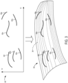
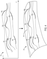
Figs. 3 and4 is an illustration of the adaptive fitting of interpolants onto a 3D virtual model, according to an example of the subject disclosure. -
Figs. 5 and6 are an illustration of the construction of a map to obtain a reparameterized surface to connect extended features curves, according to an example of the subject disclosure. -
Fig. 7 is a flowchart of a modeling method according to an example of the subject disclosure. -
Fig. 8 is an illustration of an aircraft that can be modeled by a modeling system according to an example of the subject disclosure. -
Fig. 9 is a schematic diagram illustrating an exemplary computing system that can be used to implement the modeling system ofFigs. 1-7 . - In view of the above issues, as shown in
Fig. 1 , a schematic diagram of amodeling system 10 is depicted comprising aserver computing device 12 which includes one ormore processors 14, which can be communicatively coupled to anetwork 22. Theserver computing device 12 further comprisesnon-volatile memory 16 storing a three-dimensional (3D)virtual model 30 andinstructions 32 that, when executed by theprocessor 14, cause theprocessor 14 to retrieve the 3Dvirtual model 30 from thenon-volatile memory 16. The 3Dvirtual model 30 can be of an aircraft or an aircraft component, or other manufactured parts or components, for example, as illustrated inFig. 8 . The sizes of the 3Dvirtual model 30 are not particularly limited-the 3Dvirtual model 30 can be of micron-scale objects in such applications as printed circuit boards or medical devices, or of over-sized objects. - The 3D
virtual model 30 is the mathematical representation of the surface geometry of an object, so that computer-rendered images of the object can be created from any angle. The 3Dvirtual model 30 can be a tensor-product spline surface model comprising polynomial splines and their tensor products. - The
non-volatile memory 16 can further store aU-V mapping 50, onto which one or more feature curves of the 3Dvirtual model 30 can be projected to produce a plurality of two-dimensional curves (U-V curves). The U-V mapping is a parameterized surface and can be a piecewise polynomial mapping between a two-dimensional rectangular parameter domain and three-dimensional space. - The
server computing device 12 includes anetwork interface 18 to affect the communicative coupling to thenetwork 22 and, through thenetwork 22, aclient computing device 24. Theclient computing device 24 comprises adisplay 28 which is configured to display an adaptively fitted 3Dvirtual model 26 which is outputted by theserver computing device 12.Network interface 18 can include a physical network interface, such as a network adapter. - The
server computing device 12 can be a special-purpose computer, adapted for reliability and high-bandwidth communications. Thus, thesystem 10 can be embodied in a cluster of individual hardware server computers, for example. Theprocessor 14 can be multi-core processors suitable for handling large amounts of information. Theprocessor 14 is communicatively coupled tonon-volatile memory 16 storing a 3Dvirtual model 30,U-V mapping 50, andinstructions 32 which can be executed by theprocessor 14 to effectuate the techniques disclosed herein on concert with theclient computing device 24 as shown and described below. Thenon-volatile memory 16 can be in a Redundant Array of Inexpensive Disk drives (RAID) configuration for added reliability. Theprocessor 14 can also be communicatively coupled to graphical co-processors (GPU) 20.Graphical co-processors 20 can expedite the technique disclosed herein by performing operations in parallel. - The
processor 14 is configured to execute amodeling application 15. Themodeling application 15 is configured to retrieve a 3Dvirtual model 30 from thenon-volatile memory 16, define a first parameter domain, parameterize the 3Dvirtual model 30 over the first parameter domain to thereby generate aU-V mapping 50, which is a parameterized surface representing the 3Dvirtual model 30, identify one or more feature curves in the 3Dvirtual model 30, and project the one or more feature curves in the 3Dvirtual model 30 into the first parameter domain of the parameterizedsurface 50 to generate a plurality of two-dimensional curves in the first parameter domain of the parameterized surface. When generating the plurality of two-dimensional curves, themodeling application 15 can be configured to divide the plurality of two-dimensional U-V curves into horizontal feature curves and vertical feature curves. In some examples, themodeling application 15 can be configured to extend each of the horizontal feature curves and the vertical feature curves. - The
modeling application 15 is further configured to define a second parameter domain, and construct a map between the first parameter domain and the second parameter domain, according to which an image of each projected feature curve is contained in a fixed value of a parameter domain variable of the second parameter domain. The map is invertible, and maps a boundary of the first parameter domain to a boundary of the second parameter domain. In constructing the map between the first parameter domain and the second parameter domain, themodeling application 15 can define horizontal interpolants connecting the horizontal feature curves, and define vertical interpolants connecting the vertical feature curves. - The
modeling application 15 is further configured to compose an inverse of the map with the parameterized surface to obtain a reparameterized surface, so as to adaptively fit the horizontal interpolants and the vertical interpolants on theU-V mapping 50 of the 3Dvirtual model 30, so that the feature curves are isoparametric curves of the reparameterized surface within a predetermined tolerance. The adaptively fitted 3Dvirtual model 26 with the reparameterized surface is then outputted on thedisplay 28. Although adaptive fitting is given in this example, it will be appreciated that alternative fitting schemes can also be applied to fit the interpolants to lie on the reparameterized surface within the predetermined tolerance. -
Fig. 2 shows an illustration of the construction of a map for obtaining a reparameterized surface according to an example of the present disclosure. In this illustration, theU-V mapping 50 has a plurality of two-dimensional U-V curves 52a-e, 54a-c which are divided intohorizontal feature curves 52a-e (indicated as the bold lines) andvertical feature curves 54a-c. In one example, an angle of a line connecting the start point and the end point of a curve is calculated as an arctangent value. If this arctangent value is less than 45 degrees, the curve is categorized as a horizontal feature curve. Otherwise, if the arctangent value is 45 degrees or greater, the curve is categorized as a vertical feature curve. - As shown in
Fig. 2 , a horizontal map function G-1 subsequently straightens all thehorizontal feature curves 52a-e into straighthorizontal lines 56a-e, and a vertical map function H-1 straightens all thevertical feature curves 54a-c into straightvertical lines 58a-c. Horizontal map function G-1 and vertical map function H-1 are combined as the coordinates of a function F-1 that maps to the second parameter domain. The inverse of function F-1 maps horizontal lines in the second parameter domain to horizontal feature curves in the first parameter domain, and vertical lines in the second parameter domain to vertical feature curves in the first parameter domain. - Referring to
Fig. 3 , the projection of one or more feature curves of the 3Dvirtual model 30 onto aU-V mapping 50, which is a parameterized surface, is depicted. A U-V coordinate is determined and stored for each vertex in a mesh of the 3D image, so that the contours, vertices, faces, and edges of the 3D image in the 3D space correspond to those in theU-V mapping 50. Accordingly, theprocessor 14 defines a first parameter domain (U-V space), parameterizes the 3Dvirtual model 30 over the first parameter domain (U-V space) to thereby generate a parameterizedsurface 50 representing the 3Dvirtual model 30, and projects the one or more feature curves in the 3Dvirtual model 30 into the first parameter domain (U-V space) of the parameterizedsurface 50 to generate a plurality of two-dimensional curves 52l-q in the first parameter domain of the parameterizedsurface 50. - However, in the example of
Fig. 3 , the feature curves 52l-q in theU-V mapping 50 do not yet align with horizontal or vertical lines in parameter space. Therefore, as shown in the example ofFig. 4 , each of the feature curves 52l-q are extended. Then, adaptive fitting is performed to fit the horizontal function G-1 and the vertical function H-1 which form the coordinates of a function F-1 that maps horizontal feature curves to straight horizontal lines in the second parameter space and vertical feature curves to straight vertical lines in the second parameter space. The composition from the second parameter space through the inverse of the function F-1 and along the U-V surface parameterization map to the 3D surface is adaptively fit to form a second 3D surface parameterization so that the horizontal and vertical feature curves occur as constant isoparametric curves of the second parameterization to within a predetermined tolerance. As shown inFig. 4 , the horizontal feature curves and the vertical feature curves are adaptively fitted through the second parameterization of thevirtual model 26 so that the feature curves 52l-q occur asU-V curves 34 of the reparameterized surface. Although adaptive fitting is given in this example, it will be appreciated that alternative fitting schemes can also be applied to fit the second reparameterization so that the horizontal and vertical feature curves are isoparametric curves and align with theoriginal feature 3D feature curves to within the predetermined tolerance. -
Fig. 5 is an example of a process to construct horizontal map functions. In this example, a function above the U-V parameter domain is constructed by placing the extended horizontal feature curves at fixed heights along the H direction and interpolating a monotonically increasing surface between them. The horizontal map H-1 is adaptively fit so that its graph matches the monotonic interpolant to within a predetermined tolerance. Referring toFig. 5 , the feature curves 60a, 60b are first extended to the right and to the left. Then, the extended feature curves are shifted to fixed heights in three-dimensions along the H-axis as shown inFig. 5 . Then, as shown inFig. 6 , agraph surface 62 is obtained which connects the feature curves 60a, 60b monotonically along the H-axis, so that thegraph surface 62 monotonically increases between the feature curves 60a, 60b. In alternative examples, thegraph surface 62 does not connect the feature curves 60a, 60b, but rather slightly overshoots or undershoots points on the feature curves 60a, 60b. Thegraph surface 62 can also skip certain feature curves by considering two feature curves that are close together as a 'shared' feature curve. For example, when the feature curves 60a, 60b are determined to be close together by determining that a separation distance between the feature curves 60a, 60b is below a predetermined threshold, then featurecurves graph surface 62 can interpolatefeature curve 60a and not featurecurve 60b. It will be appreciated that, in 3D modeling applications involving objects with relatively complicated shapes, there can be thousands of these feature curves that are all connected by a graph surface monotonically, so that the graph surface monotonically increases across all of the feature curves. -
Fig. 7 shows anexemplary method 100 for virtual modeling according to an example of the present disclosure. The following description ofmethod 100 is provided with reference to the software and hardware components described above and shown inFigs. 1 through 6 . It will be appreciated thatmethod 100 also can be performed in other contexts using other suitable hardware and software components. - At
step 102, a first parameter domain is defined. Atstep 104, the 3D virtual model is parameterized over the first domain to thereby generate a parameterized surface representing the 3D virtual model. The parameterized surface can be a spline surface, for example. Atstep 106, one or more feature curves are identified in the 3D virtual model. At step 108, the one or more feature curves in the 3D virtual model are projected into the first parameter domain of the parameterized surface to generate a plurality of two-dimensional U-V curves in the first parameter domain of the parameterized surface. Step 108 can further include step 108a. At step 108a, the plurality of two-dimensional U-V curves are divided into horizontal feature curves and vertical feature curves. In this step, an angle of a line connecting the start point and the end point of a curve can be calculated. If this angle is less than 45 degrees, the curve is categorized as a horizontal feature curve. Otherwise the curve is categorized as a vertical feature curve. - Step 108 can further include step 108b. At step 108b, each of the horizontal feature curves and the vertical feature curves are extended through tangent fields in order to reach the parametric boundary of the initially defined first parameter domain. For a given horizontal feature curve, the curve can be extended to the right and to the left by integrating through the tangent field of the curve, assuming that the curve runs horizontally. For a given vertical feature curve, the curve can be extended to the right and to the left by integrating through the tangent field of the curve, assuming that the curve runs vertically. The tangent fields can comprise distance-weighted averages of tangents at each projection of the feature curves. The distance-weighted averages of the tangents can be calculated by calculating a sum of the inverse squares of the distances of the tangents at each projection of the feature curves. Each extended feature curve can be assigned a parameter value based on an integration under the feature curve.
- At
step 110, a second parameter domain is defined. Atstep 112, a map is constructed between the first parameter domain and the second parameter domain. According to the map, an image of each projected feature curve is contained in a fixed value of a parameter domain variable of the second parameter domain. The map is invertible, and maps a boundary of the first parameter domain to a boundary of the second parameter domain. Step 112 for map construction can includestep 112a. Atstep 112a, a horizontal map function is constructed from a graph surface that interpolates the horizontal feature curves shifted to constant heights above the first parameter space. The defined horizontal map function is a component of the map to the second parameter domain that straightens the projected feature curves. In this step, at step 112aa, horizontal feature curves are sorted for surface fitting. The feature curves can be rearranged to be ordered based on ascending assigned parameter values. At step 112ab, horizontal feature curves are shifted to a fixed height above the U-V plane. At step 112ac, the shifted horizontal curves are connected with a graph surface which is a monotonic interpolant. At step 112ad, the horizontal feature curves are adaptively fitted on the graph surface. Other alternative fitting schemes can also be applied to fit the horizontal feature curves on the graph surface within a predetermined tolerance. - Step 112 for map construction can include
step 112b. Atstep 112b, a vertical map function is constructed from a graph surface that interpolates the vertical feature curves shifted to constant heights above the first parameter space. The defined vertical map function is a component of the map to the second parameter domain that straightens the projected feature curves. In this step, at step 112ba, vertical feature curves are sorted for surface fitting. The extended feature curves can be rearranged to be ordered based on ascending assigned parameter values. At step 112bb, vertical feature curves are shifted to a fixed height above the U-V plane. At step 112bc, the shifted vertical feature curves are connected with a graph surface which is a monotonic interpolant. At step 112bd, the vertical feature curves are adaptively fitted on the graph surface. Other alternative fitting schemes can also be applied to fit the vertical feature curves on the graph surface within a predetermined tolerance. - At
step 114, an inverse of the map from the first parameter space to the second parameter space is composed with the parameterized surface to obtain a reparameterized surface in which the feature curves are isoparametric curves to within a predetermined tolerance. The composition can be adaptively fit to produce a 3D spline surface. Although adaptive fitting is given in this example, it will be appreciated that alternative fitting schemes can also be applied, so that the feature curves occur as isoparametric curves up to a given tolerance. Atstep 116, the reparameterized surface is outputted. -
Fig. 8 is an image of anaircraft 200 according to some embodiments. It will be appreciated that theaircraft 200 or acomponent 202 thereof can be the object that is modeled by the 3D virtual model in accordance with thesystem 10 andmethod 100 of the subject disclosure. - The systems and processes described herein have the potential benefit of building 3D virtual models with spline surfaces that model complicated shapes accurately and efficiently without using an excessive number of control points, so that the isoparametric curves of the 3D virtual model track the features of the 3D virtual model, including curvatures, folds, and creases without 'bumps' or 'sagging'. Thus, the 3D virtual model of the present disclosure improves accuracy. By reducing the number of control points in the 3D virtual model, the model becomes easier to work with for designers and programmers. Conventionally, designers and programmers would synthesize data represented in multiple separate geometric patches for each feature detected in the model, which was processor and memory intensive, so that the synthesized model could be input into analysis software programs. Producing a synthesized version of the patches is a time-consuming, processor intensive, and memory intensive process. In contrast, the 3D virtual model of the present disclosure can save processor and memory resources by avoiding such laborious synthesis of separate geometries. Further, by fitting the feature curves to isoparametric curves of the 3D virtual model, they can be used as engineering features in computer-aided design (CAD) applications, thereby improving the technical compatibility of the model as compared to prior approaches.
- The fitted 3D virtual models outputted by the systems and processes described herein can be used in various applications. For example, the fitted 3D virtual model can be used in additive manufacturing applications, for example, to optimize the weight, cost, and/or function of a 3D manufactured object through 3D model modifications. The fitted 3D virtual model can also be used to detect surface anomalies during inspection of the skin of manufactured or assembled parts of aircraft using three-dimensional modeling, for example.
-
Fig. 9 illustrates anexemplary computing system 300 that can be utilized to implement thesystem 10 andmethod 100 described above.Computing system 300 includes alogic processor 302,volatile memory 304, and anon-volatile storage device 306.Computing system 300 can optionally include adisplay subsystem 308,input subsystem 310,communication subsystem 312 connected to a computer network, and/or other components not shown inFig. 9 . These components are typically connected for data exchange by one or more data buses when integrated into single device, or by a combination of data buses, network data interfaces, and computer networks when integrated into separate devices connected by computer networks. - The
non-volatile storage device 306 stores various instructions, also referred to as software, that are executed by thelogic processor 302.Logic processor 302 includes one or more physical devices configured to execute the instructions. For example, thelogic processor 302 can be configured to execute instructions that are part of one or more applications, programs, routines, libraries, objects, components, data structures, or other logical constructs. Such instructions can be implemented to perform a task, implement a data type, transform the state of one or more components, achieve a technical effect, or otherwise arrive at a desired result. - The
logic processor 302 can include one or more physical processors (hardware) configured to execute software instructions. Additionally or alternatively, thelogic processor 302 can include one or more hardware logic circuits or firmware devices configured to execute hardware-implemented logic or firmware instructions. Processors of thelogic processor 302 can be single-core or multi-core, and the instructions executed thereon can be configured for sequential, parallel, and/or distributed processing. Individual components of thelogic processor 302 optionally can be distributed among two or more separate devices, which can be remotely located and/or configured for coordinated processing. Aspects of thelogic processor 302 can be virtualized and executed by remotely accessible, networked computing devices configured in a cloud-computing configuration. In such a case, these virtualized aspects are run on different physical logic processors of various different machines, it will be understood.Non-volatile storage device 306 includes one or more physical devices configured to hold instructions executable by the logic processors to implement the methods and processes described herein. When such methods and processes are implemented, the state ofnon-volatile storage device 306 can be transformed-e.g., to hold different data.Non-volatile storage device 306 can include physical devices that are removable and/or built-in.Non-volatile storage device 306 can include optical memory (e.g., CD, DVD, HD-DVD, Blu-Ray Disc, etc.), semiconductor memory (e.g., ROM, EPROM, EEPROM, FLASH memory, etc.), and/or magnetic memory (e.g., hard-disk drive, floppy-disk drive, tape drive, MRAM, etc.), or other mass storage device technology.Non-volatile storage device 306 can include nonvolatile, dynamic, static, read/write, read-only, sequential-access, location-addressable, file-addressable, and/or content-addressable devices. It will be appreciated thatnon-volatile storage device 306 is configured to hold instructions even when power is cut to thenon-volatile storage device 306. -
Volatile memory 304 can include physical devices that include random access memory.Volatile memory 304 is typically utilized bylogic processor 302 to temporarily store information during processing of software instructions. It will be appreciated thatvolatile memory 304 typically does not continue to store instructions when power is cut to thevolatile memory 304. - Aspects of
logic processor 302,volatile memory 304, andnon-volatile storage device 306 can be integrated together into one or more hardware-logic components. Such hardware-logic components can include field-programmable gate arrays (FPGAs), program- and application-specific integrated circuits (PASIC / ASICs), program- and application-specific standard products (PSSP / ASSPs), system-on-a-chip (SOC), and complex programmable logic devices (CPLDs), for example. - The terms "module," "program," and "engine" can be used to describe an aspect of the
modeling system 10 typically implemented in software by a processor to perform a particular function using portions of volatile memory, which function involves transformative processing that specially configures the processor to perform the function. Thus, a module, program, or engine can be instantiated vialogic processor 302 executing instructions held bynon-volatile storage device 306, using portions ofvolatile memory 304. It will be understood that different modules, programs, and/or engines can be instantiated from the same application, service, code block, object, library, routine, API, function, etc. Likewise, the same module, program, and/or engine can be instantiated by different applications, services, code blocks, objects, routines, APIs, functions, etc. The terms "module," "program," and "engine" can encompass individual or groups of executable files, data files, libraries, drivers, scripts, database records, etc. -
Display subsystem 308 typically includes one or more displays, which can be physically integrated with or remote from a device that houses thelogic processor 302. Graphical output of the logic processor executing the instructions described above, such as a graphical user interface, is configured to be displayed ondisplay subsystem 308. -
Input subsystem 310 typically includes one or more of a keyboard, pointing device (e.g., mouse, trackpad, finger operated pointer), touchscreen, microphone, and camera. Other input devices can also be provided. -
Communication subsystem 312 is configured to communicatively couple various computing devices described herein with each other, and with other devices.Communication subsystem 312 can include wired and/or wireless communication devices compatible with one or more different communication protocols. As non-limiting examples, the communication subsystem can be configured for communication via a wireless telephone network, or a wired or wireless local- or wide-area network by devices such as a 3G, 4G, 5G, or 6G radio, WIFI card, ethernet network interface card, BLUETOOTH radio, etc. In some embodiments, the communication subsystem can allowcomputing system 10 to send and/or receive messages to and/or from other devices via a network such as the Internet. It will be appreciated that one or more of the computer networks via whichcommunication subsystem 312 is configured to communicate can include security measures such as user identification and authentication, access control, malware detection, enforced encryption, content filtering, etc., and can be coupled to a wide area network (WAN) such as the Internet. - The subject disclosure includes all novel and non-obvious combinations and subcombinations of the various features and techniques disclosed herein. The various features and techniques disclosed herein are not necessarily required of all examples of the subject disclosure. Furthermore, the various features and techniques disclosed herein can define patentable subject matter apart from the disclosed examples and can find utility in other implementations not expressly disclosed herein.
- To the extent that terms "includes," "including," "has," "contains," and variants thereof are used herein, such terms are intended to be inclusive in a manner similar to the term "comprises" as an open transition word without precluding any additional or other elements.
- Further, the disclosure comprises configurations according to the following clauses.
-
Clause 1. A modeling system comprising: at least one processor, communicatively coupled to non-volatile memory and instructions that, when executed by the processor, cause the processor to: retrieve from the non-volatile memory a 3D virtual model of an object; define a first parameter domain; parameterize the 3D virtual model over the first parameter domain to thereby generate a parameterized surface representing the 3D virtual model; identify one or more feature curves in the 3D virtual model; project the one or more feature curves in the 3D virtual model into the first parameter domain of the parameterized surface to generate a plurality of two-dimensional curves in the first parameter domain of the parameterized surface; define a second parameter domain; construct a map between the first parameter domain and the second parameter domain, according to which an image of each projected feature curve is contained in a fixed value of a parameter domain variable of the second parameter domain; and the map is invertible, and maps a boundary of the first parameter domain to a boundary of the second parameter domain; compose an inverse of the map with the parameterized surface to obtain a reparameterized surface; and output the reparameterized surface. - Clause 2. The modeling system of
clause 1, wherein the map comprises a horizontal feature curve interpolant and vertical feature curve interpolant; and the reparameterized surface is obtained by: dividing the plurality of two-dimensional curves into horizontal feature curves and vertical feature curves; constructing a horizontal interpolant connecting the horizontal feature curves; constructing a vertical interpolant connecting the vertical feature curves; and fitting the horizontal interpolant and the vertical interpolant as a function to the second parameter space so that the feature curves occur as horizontal and vertical grid lines in the second parameter space. - Clause 3. The modeling system of
clause 1 or 2, wherein each of the horizontal feature curves and the vertical feature curves are extended by integrating through tangent fields of the feature curves. - Clause 4. The modeling system of any of
clauses 1 to 3, wherein the tangent fields comprise distance-weighted averages of tangents at each projection of the feature curves. Clause 5. The modeling system of any ofclauses 1 to 4, wherein the feature curves lie on isoparametric lines of the map, within a predetermined tolerance. - Clause 6. The modeling system of any of
clauses 1 to 5, wherein adaptive fitting is used to fit the horizontal and vertical interpolants. - Clause 7. The modeling system of any of
clauses 1 to 6, wherein during the definition of the interpolant, the feature curves are rearranged to be ordered based on ascending assigned parameter values. - Clause 8. The modeling system of any of clauses 2 to 7, wherein the definition of the interpolant involves constructing the map such that the feature curves occur as constant height intersections with the interpolant, and the interpolant monotonically increases between feature curves.
- Clause 9. The modeling system of any of
clauses 1 to 8, wherein the reparameterized interpolant is a graph surface which overshoots or undershoots points on the feature curves. -
Clause 10. The modeling system of any ofclauses 1 to 9, wherein the 3D virtual model is a tensor-product spline surface model. - Clause 11. A modeling method comprising: retrieving a 3D virtual model of an object; defining a first parameter domain; parameterizing the 3D virtual model over the first parameter domain to thereby generate the parameterized surface representing the 3D virtual model; identifying one or more feature curves in the 3D virtual model; projecting the one or more feature curves in the 3D virtual model into the first parameter domain of the parameterized surface to generate a plurality of two-dimensional curves in the first parameter domain of the parameterized surface; defining a second parameter domain; construct a map between the first parameter domain and the second parameter domain, according to which an image of each projected feature curve is contained in a fixed value of a parameter domain variable of the second parameter domain; and the map is invertible, and maps a boundary of the first parameter domain to a boundary of the second parameter domain; composing an inverse of the map with the parameterized surface to obtain a reparameterized surface; and outputting the reparameterized surface.
-
Clause 12. The method of clause 11, wherein the map comprises horizontal map functions and vertical map functions; the reparameterized surface is obtained by: dividing the plurality of two-dimensional curves into horizontal feature curves and vertical feature curves; constructing the horizontal map functions to define horizontal interpolants connecting the horizontal feature curves; constructing the vertical map functions to define vertical interpolants connecting the vertical feature curves; and fitting the horizontal interpolants and the vertical interpolants so that the feature curves occur as horizontal and vertical grid lines in the second parameter space. - Clause 13. The method of
clause 11 or 12, wherein the tangent fields comprises distance-weighted averages of tangents at each projection of the feature curves. -
Clause 14. The method of any of clauses 11 to 13, wherein the fitted horizontal feature curves and the fitted vertical feature curves lie on the reparameterized surface along isoparametric lines, within a predetermined tolerance. -
Clause 15. The method of any of clauses 11 to 14, wherein adaptive fitting is used to fit the plurality of two-dimensional curves in the parameter domain of the reparameterized surface. -
Clause 16. The method of any of clauses 11 to 15, wherein during the construction of the map, the feature curves are rearranged to be ordered based on ascending assigned parameter values. - Clause 17. The method of any of clauses 11 to 16, wherein the plurality of two-dimensional curves are divided into horizontal feature curves and vertical feature curves by categorizing two-dimensional curves with an arctangent value of less than 45 degrees as horizontal feature curves, and categorizing two-dimensional curves with an arctangent value of 45 degrees or greater as vertical feature curves.
-
Clause 18. The method of any of clauses 11 to 17, wherein the definition of the interpolants involves obtaining the reparameterized surface such that the feature curves occur as constant height intersections with the interpolant, and the reparameterized interpolant monotonically increases between feature curves. - Clause 19. The method of any of clauses 11 to 18, wherein the reparameterized interpolant is a graph surface which overshoots or undershoots points on the feature curves.
-
Clause 20. A modeling system comprising: at least one processor, communicatively coupled to non-volatile memory storing a tensor-product spline surface model and instructions that, when executed by the processor, cause the processor to: retrieve from the non-volatile memory the tensor-product spline surface model of an object; define a first parameter domain; parameterize the tensor-product spline surface model over the first parameter domain to thereby generate a parameterized surface representing the tensor-product spline surface model; identify one or more feature curves in the tensor-product spline surface model; project the one or more feature curves in the tensor-product spline surface model into the first parameter domain of the parameterized surface to generate a plurality of two-dimensional curves in the first parameter domain of the parameterized surface; define a second parameter domain; construct a map between the first parameter domain and the second parameter domain, according to which an image of each projected feature curve is contained in a fixed value of a parameter domain variable of the second parameter domain; and the map is invertible, and maps a boundary of the first parameter domain to a boundary of the second parameter domain; compose an inverse of the map with the parameterized surface to obtain a reparameterized surface; and output the reparameterized surface, wherein to obtain the reparameterized surface, the instructions, when executed by the processor, cause the processor to: divide the plurality of two-dimensional curves into horizontal feature curves and vertical feature curves; and construct the map such that the feature curves occur as horizontal and vertical grid lines in the second parameter space, and the interpolating surface monotonically increases between feature curves.
Claims (15)
- A modeling system (10) comprising:
at least one processor (14), communicatively coupled to non-volatile memory (16) and instructions (32) that, when executed by the processor (14), cause the processor (14) to:retrieve from the non-volatile memory (16) a 3D virtual model (30) of an object;define a first parameter domain;parameterize the 3D virtual model (30) over the first parameter domain to thereby generate a parameterized surface representing the 3D virtual model (30);identify one or more feature curves (52a-e, 54a-c) in the 3D virtual model (30);project the one or more feature curves (52a-e, 54a-c) in the 3D virtual model (30) into the first parameter domain of the parameterized surface to generate a plurality of two-dimensional curves (52a-e, 54a-c) in the first parameter domain of the parameterized surface;define a second parameter domain;construct a map between the first parameter domain and the second parameter domain, according to whichan image of each projected feature curve (52a-e, 54a-c) is contained in a fixed value of a parameter domain variable of the second parameter domain; andthe map is invertible, and maps a boundary of the first parameter domain to a boundary of the second parameter domain;compose an inverse of the map with the parameterized surface to obtain a reparameterized surface (62); andoutput the reparameterized surface (62). - The modeling system (10) of claim 1, whereinthe map comprises a horizontal feature curve interpolant and vertical feature curve interpolant; andthe reparameterized surface (62) is obtained by:dividing the plurality of two-dimensional curves into horizontal feature curves (52a-e) and vertical feature curves (54a-c);constructing a horizontal interpolant connecting the horizontal feature curves (52a-e);constructing a vertical interpolant connecting the vertical feature curves (54a-c); andfitting the horizontal interpolant and the vertical interpolant as a function to the second parameter space so that the feature curves (52a-e, 54a-c) occur as horizontal and vertical grid lines in the second parameter space.
- The modeling system (10) of claim 2, wherein at least one of:each of the horizontal feature curves (52a-e) and the vertical feature curves (54a-c) are extended by integrating through tangent fields of the feature curves (52a-e, 54a-c);
the tangent fields comprise distance-weighted averages of tangents at each projection of the feature curves (52a-e, 54a-c); orthe feature curves (52a-e, 54a-c) lie on isoparametric lines of the map, within a predetermined tolerance. - The modeling system (10) of any preceding claim, wherein adaptive fitting is used to fit the horizontal and vertical interpolants and optionally wherein during the definition of the interpolant, the feature curves (52a-e, 54a-c) are rearranged to be ordered based on ascending assigned parameter values.
- The modeling system (10) of claim 2, wherein the definition of the interpolant involves constructing the map such that the feature curves (52a-e, 54a-c) occur as constant height intersections with the interpolant, and the interpolant monotonically increases between feature curves (52a-e, 54a-c) and optionally wherein the reparameterized interpolant is a graph surface which overshoots or undershoots points on the feature curves (52a-e, 54a-c).
- The modeling system (10) of any preceding claim, wherein the 3D virtual model (30) is a tensor-product spline surface model.
- A modeling method (100) comprising:retrieving a 3D virtual model (30) of an object;defining a first parameter domain;parameterizing the 3D virtual model (30) over the first parameter domain to thereby generate the parameterized surface representing the 3D virtual model (30);identifying one or more feature curves (52a-e, 54a-c) in the 3D virtual model (30);projecting the one or more feature curves (52a-e, 54a-c) in the 3D virtual model (30) into the first parameter domain of the parameterized surface to generate a plurality of two-dimensional curves (52a-e, 54a-c) in the first parameter domain of the parameterized surface;defining a second parameter domain;construct a map between the first parameter domain and the second parameter domain, according to whichan image of each projected feature curve (52a-e, 54a-c) is contained in a fixed value of a parameter domain variable of the second parameter domain; andthe map is invertible, and maps a boundary of the first parameter domain to a boundary of the second parameter domain;composing an inverse of the map with the parameterized surface to obtain a reparameterized surface (62); andoutputting the reparameterized surface (62).
- The method (100) of claim 7, whereinthe map comprises horizontal map functions and vertical map functions;the reparameterized surface (62) is obtained by:dividing the plurality of two-dimensional curves (52a-e, 54a-c) into horizontal feature curves (52a-e) and vertical feature curves (54a-c);constructing the horizontal map functions to define horizontal interpolants connecting the horizontal feature curves (52a-e);constructing the vertical map functions to define vertical interpolants connecting the vertical feature curves (54a-c); andfitting the horizontal interpolants and the vertical interpolants so that the feature curves (52a-e, 54a-c) occur as horizontal and vertical grid lines in the second parameter space.
- The method (100) of claim 8, wherein the tangent fields comprise distance-weighted averages of tangents at each projection of the feature curves (52a-e, 54a-c).
- The method (100) of any of claims 7 to 9, wherein the fitted horizontal feature curves (52a-e) and the fitted vertical feature curves (54a-c) lie on the reparameterized surface (62) along isoparametric lines, within a predetermined tolerance.
- The method (100) of any of claims 7 to 10, wherein adaptive fitting is used to fit the plurality of two-dimensional curves (52a-e, 54a-c) in the parameter domain of the reparameterized surface (62) and optionally.
- The method (100) of claim 11, wherein during the construction of the map, the feature curves (52a-e, 54a-c) are rearranged to be ordered based on ascending assigned parameter values.
- The method (100) of any of claims 8 to 12, wherein the plurality of two-dimensional curves are divided into horizontal feature curves (52a-e) and vertical feature curves (54a-c) by categorizing two-dimensional curves with an arctangent value of less than 45 degrees as horizontal feature curves (52a-e), and categorizing two-dimensional curves with an arctangent value of 45 degrees or greater as vertical feature curves (54a-c).
- The method (100) of any of claims 8 to 13, wherein the definition of the interpolants involves obtaining the reparameterized surface (62) such that the feature curves (52a-e, 54a-c) occur as constant height intersections with the interpolant, and the reparameterized interpolant monotonically increases between feature curves (52a-e, 54a-c).
- The method (100) of claim 14, wherein the reparameterized interpolant is a graph surface which overshoots or undershoots points on the feature curves (52a-e, 54a-c).
Applications Claiming Priority (1)
| Application Number | Priority Date | Filing Date | Title |
|---|---|---|---|
| US17/812,996 US12272018B2 (en) | 2022-07-15 | 2022-07-15 | Modeling system for 3D virtual model |
Publications (1)
| Publication Number | Publication Date |
|---|---|
| EP4307235A1 true EP4307235A1 (en) | 2024-01-17 |
Family
ID=85726746
Family Applications (1)
| Application Number | Title | Priority Date | Filing Date |
|---|---|---|---|
| EP23163447.8A Pending EP4307235A1 (en) | 2022-07-15 | 2023-03-22 | Modeling system for 3d virtual model based on surface reparametrization |
Country Status (3)
| Country | Link |
|---|---|
| US (1) | US12272018B2 (en) |
| EP (1) | EP4307235A1 (en) |
| CN (1) | CN117422818A (en) |
Cited By (1)
| Publication number | Priority date | Publication date | Assignee | Title |
|---|---|---|---|---|
| EP4651092A3 (en) * | 2024-05-14 | 2025-12-24 | The Boeing Company | Curve-wise surface flattening for composite layup |
Families Citing this family (1)
| Publication number | Priority date | Publication date | Assignee | Title |
|---|---|---|---|---|
| US20230153488A1 (en) * | 2021-11-18 | 2023-05-18 | Tira Technologies Private Limited | Apparatus and method for simulating a three-dimensional object |
Citations (1)
| Publication number | Priority date | Publication date | Assignee | Title |
|---|---|---|---|---|
| US6271856B1 (en) * | 1998-11-19 | 2001-08-07 | Paraform, Inc. | Creating and modifying parameterizations of surfaces |
Family Cites Families (166)
| Publication number | Priority date | Publication date | Assignee | Title |
|---|---|---|---|---|
| JPH0785271B2 (en) * | 1986-06-27 | 1995-09-13 | 株式会社日立製作所 | Shape modeling method |
| US4999789A (en) * | 1987-02-05 | 1991-03-12 | Hewlett-Packard Co. | Method and apparatus for trimming B-spline descriptions of patches in a high performance three dimensional graphics system |
| US5243694A (en) * | 1987-02-05 | 1993-09-07 | Hewlett-Packard Company | Method and apparatus for trimming B-spline descriptions of patches in a high performance three dimensional graphics system |
| US5107444A (en) * | 1988-09-13 | 1992-04-21 | Computer Design, Inc. | Method and apparatus for flattening three-dimensional surfaces |
| JP2730195B2 (en) * | 1989-06-30 | 1998-03-25 | 三菱電機株式会社 | Coupling vibration characteristic analyzer |
| US5255352A (en) * | 1989-08-03 | 1993-10-19 | Computer Design, Inc. | Mapping of two-dimensional surface detail on three-dimensional surfaces |
| JPH0567179A (en) * | 1991-09-10 | 1993-03-19 | Hitachi Ltd | Method and device for form data processing |
| US6084586A (en) * | 1991-10-29 | 2000-07-04 | Sony Corporation | Method and apparatus for forming objects based on free-form curves and free-form surfaces generated by minimizing sum of distances from an input series of points to a free-form curve |
| US5592599A (en) * | 1991-12-18 | 1997-01-07 | Ampex Corporation | Video special effects system with graphical operator interface |
| US5581672A (en) * | 1991-12-19 | 1996-12-03 | Aerohydro, Inc. | System of relational entities for object-oriented computer-aided geometric design |
| EP0551543A1 (en) * | 1992-01-16 | 1993-07-21 | Hewlett-Packard GmbH | Method of modifying a geometric object and computer aided design system |
| JP3089792B2 (en) * | 1992-03-04 | 2000-09-18 | ソニー株式会社 | Hidden surface discrimination method for image data |
| US5619625A (en) * | 1993-05-28 | 1997-04-08 | Ricoh Company, Ltd. | Method for interpolating smooth free-form surfaces into curve mesh including composite curves |
| US5550960A (en) * | 1993-08-02 | 1996-08-27 | Sun Microsystems, Inc. | Method and apparatus for performing dynamic texture mapping for complex surfaces |
| CA2140621A1 (en) * | 1993-11-09 | 1995-05-10 | Gerhard Roth | Estimation of surface geometry from relative range images |
| JP3064799B2 (en) * | 1994-03-29 | 2000-07-12 | ヤマハ株式会社 | Texture mapping device |
| US5673377A (en) * | 1994-09-02 | 1997-09-30 | Ray Dream, Inc. | Method and system for displaying a representation of a three-dimensional object with surface features that conform to the surface of the three-dimensional object |
| JPH0896165A (en) * | 1994-09-29 | 1996-04-12 | Fujitsu Ltd | Image generating method and image generating apparatus |
| US5577176A (en) * | 1994-11-23 | 1996-11-19 | Computervision Corporation | Method and apparatus for displaying a cursor along a two dimensional representation of a computer generated three dimensional surface |
| US5886703A (en) * | 1995-02-01 | 1999-03-23 | Virtus Corporation | Perspective correct texture mapping system and methods with intelligent subdivision |
| US5559334A (en) * | 1995-05-22 | 1996-09-24 | General Electric Company | Epipolar reconstruction of 3D structures |
| US6862023B1 (en) * | 1995-08-18 | 2005-03-01 | Mohammad Salim Shaikh | Fully integrated machinable profile based parametric solid modeler |
| JP3341548B2 (en) * | 1995-11-14 | 2002-11-05 | ミノルタ株式会社 | Method and apparatus for generating three-dimensional shape data |
| US5701404A (en) * | 1996-05-31 | 1997-12-23 | Softimage | Method and system for efficiently trimming a nurbs surface with a projected curve |
| US6639592B1 (en) * | 1996-08-02 | 2003-10-28 | Silicon Graphics, Inc. | Curve network modeling |
| US6249289B1 (en) * | 1996-11-27 | 2001-06-19 | Silicon Graphics, Inc. | Multi-purpose high resolution distortion correction |
| US5880736A (en) * | 1997-02-28 | 1999-03-09 | Silicon Graphics, Inc. | Method system and computer program product for shading |
| US5949424A (en) * | 1997-02-28 | 1999-09-07 | Silicon Graphics, Inc. | Method, system, and computer program product for bump mapping in tangent space |
| US5995109A (en) * | 1997-04-08 | 1999-11-30 | Lsi Logic Corporation | Method for rendering high order rational surface patches |
| US5903458A (en) * | 1997-06-06 | 1999-05-11 | Ford Global Technologies, Inc. | System and method for forming geometric features using global reparametrization |
| US6052157A (en) * | 1997-08-04 | 2000-04-18 | Innovision Labs | System and method for separating chrominance and luminance components of a color television system |
| US6600485B1 (en) * | 1998-07-03 | 2003-07-29 | Sega Enterprises, Ltd. | Polygon data generation method and image display apparatus using same |
| US6300958B1 (en) * | 1998-07-17 | 2001-10-09 | T-Surf Corp. | Global constrained parameterization of triangulated surfaces |
| US7196702B1 (en) * | 1998-07-23 | 2007-03-27 | Freedesign, Inc. | Geometric design and modeling system using control geometry |
| US8836701B1 (en) * | 1998-07-23 | 2014-09-16 | Freedesign, Inc. | Surface patch techniques for computational geometry |
| US6981695B1 (en) * | 2003-10-14 | 2006-01-03 | Polaris Industries Inc. | All terrain vehicle with multiple winches |
| EP1133257A4 (en) * | 1998-11-25 | 2007-12-26 | Univ Wake Forest | Virtual endoscopy with improved image segmentation and lesion detection |
| US6392645B1 (en) * | 1999-03-15 | 2002-05-21 | Alventive Inc. | Three dimensional geometric modeling system |
| JP4083949B2 (en) * | 1999-03-18 | 2008-04-30 | 株式会社リコー | Method for generating curved surface model by reversible rounding operation, method for generating lattice polygon model from curved surface model, recording medium for executing these methods, and method for transmitting / displaying curved surface model |
| US6683620B1 (en) * | 1999-04-21 | 2004-01-27 | Autodesk, Inc. | Relational modeling of trimmed nurbs surfaces |
| US6369815B1 (en) * | 1999-04-23 | 2002-04-09 | Spatial Technology, Inc. | Deformable modeling using generalized curve constraints |
| US6462740B1 (en) * | 1999-07-30 | 2002-10-08 | Silicon Graphics, Inc. | System for in-scene cloth modification |
| US6903742B1 (en) * | 1999-12-01 | 2005-06-07 | Microsoft Corporation | Method and apparatus for transforming and rendering graphical curves |
| US6941251B1 (en) * | 1999-12-27 | 2005-09-06 | Spatial Corp. | Method for transforming CAD model using general function composition mechanism |
| JP3829972B2 (en) * | 2000-03-06 | 2006-10-04 | サイテック株式会社 | 3D CAD system |
| US7180523B1 (en) * | 2000-03-31 | 2007-02-20 | Intel Corporation | Trimming surfaces |
| US6552725B1 (en) * | 2000-04-11 | 2003-04-22 | Corel Corporation | Heuristic method for adaptive subdivision of coons patches for rendering |
| US6871166B1 (en) * | 2000-07-23 | 2005-03-22 | Microsoft Corp. | Knitwear modeling |
| US7245299B2 (en) * | 2003-05-12 | 2007-07-17 | Adrian Sfarti | Bicubic surface real-time tesselation unit |
| USRE42534E1 (en) * | 2000-07-28 | 2011-07-12 | Adrian Sfarti | Bicubic surface real-time tesselation unit |
| US6563501B2 (en) * | 2000-07-28 | 2003-05-13 | Adrian Sfarti | Bicubic surface rendering |
| US7280108B2 (en) * | 2000-12-11 | 2007-10-09 | Adrian Sfarti | Bicubic surface rendering |
| US7076117B2 (en) * | 2001-06-19 | 2006-07-11 | International Business Machines Corporation | Methods and apparatus for cut-and-paste editing of multiresolution surfaces |
| US6833843B2 (en) * | 2001-12-03 | 2004-12-21 | Tempest Microsystems | Panoramic imaging and display system with canonical magnifier |
| US7467074B2 (en) * | 2002-02-01 | 2008-12-16 | Ford Motor Company | System and method of interactively assembling a model |
| US7200532B1 (en) * | 2002-06-14 | 2007-04-03 | University Of Kentucky Research Foundation | Subdivision surface-based geometric modeling system |
| US7212205B2 (en) * | 2002-11-12 | 2007-05-01 | Matsushita Electric Industrial Co., Ltd. | Curved surface image processing apparatus and curved surface image processing method |
| US20040113910A1 (en) * | 2002-12-12 | 2004-06-17 | Electronic Data Systems Corporation | System and method for the rebuild of curve networks in curve-based surface generation using constrained-surface fitting |
| US7512255B2 (en) * | 2003-08-22 | 2009-03-31 | Board Of Regents, University Of Houston | Multi-modal face recognition |
| US7369972B2 (en) * | 2003-11-25 | 2008-05-06 | International Business Machines Corporation | System, method, and program product for re-parameterizing three dimensional models represented as Catmull-Clark subdivision surfaces |
| US8963958B2 (en) * | 2003-12-10 | 2015-02-24 | 3D Systems, Inc. | Apparatus and methods for adjusting a texture wrapped onto the surface of a virtual object |
| US7889209B2 (en) * | 2003-12-10 | 2011-02-15 | Sensable Technologies, Inc. | Apparatus and methods for wrapping texture onto the surface of a virtual object |
| JP4111166B2 (en) * | 2004-05-07 | 2008-07-02 | コニカミノルタセンシング株式会社 | 3D shape input device |
| US7324706B2 (en) * | 2004-09-09 | 2008-01-29 | Silicon Optix Inc. | System and method for representing a general two dimensional spatial transformation |
| GB0502022D0 (en) * | 2005-02-01 | 2005-03-09 | Evans Gerald J | Meter filter |
| GB2422756B (en) * | 2005-02-01 | 2006-12-27 | Univ Bradford | Storing or transmitting data representing a 3d object |
| US7382374B2 (en) * | 2005-05-02 | 2008-06-03 | Bitplane Ag | Computerized method and computer system for positioning a pointer |
| US7756325B2 (en) * | 2005-06-20 | 2010-07-13 | University Of Basel | Estimating 3D shape and texture of a 3D object based on a 2D image of the 3D object |
| JP2007260144A (en) * | 2006-03-28 | 2007-10-11 | Olympus Medical Systems Corp | Medical image processing apparatus and medical image processing method |
| US7944443B1 (en) * | 2006-06-09 | 2011-05-17 | Pixar | Sliding patch deformer |
| US8031957B1 (en) * | 2006-07-11 | 2011-10-04 | Adobe Systems Incorporated | Rewritable lossy compression of graphical data |
| US7948488B2 (en) * | 2007-04-17 | 2011-05-24 | Autodesk, Inc. | Shape preserving mappings to a surface |
| US7844106B2 (en) * | 2007-04-23 | 2010-11-30 | Mitsubishi Electric Research Laboratories, Inc | Method and system for determining poses of objects from range images using adaptive sampling of pose spaces |
| US8005558B2 (en) * | 2007-09-14 | 2011-08-23 | Nike, Inc. | Three-dimensional design lasts for footwear |
| US7969435B1 (en) * | 2007-11-09 | 2011-06-28 | Spaceclaim Corporation, Inc. | Method for modifying any modeled surface as a lofted surface |
| US8269770B1 (en) * | 2008-02-29 | 2012-09-18 | Adobe Systems Incorporated | Tessellation of trimmed parametric surfaces by walking the surface |
| WO2009142037A1 (en) * | 2008-05-23 | 2009-11-26 | 国立大学法人横浜国立大学 | Approximation processing method and approximation processing device |
| EP2141617A1 (en) * | 2008-07-04 | 2010-01-06 | Dassault Systèmes S.A. | A computer-implemented method of design of surfaces defined by guiding curves. |
| US11907617B2 (en) * | 2008-07-18 | 2024-02-20 | Cad-Sense Llc | Surface patch techniques for computational geometry |
| JP4629131B2 (en) * | 2008-09-03 | 2011-02-09 | 大日本印刷株式会社 | Image converter |
| KR101194604B1 (en) * | 2008-12-22 | 2012-10-25 | 한국전자통신연구원 | Method and apparatus for shape deforming surface based 3d human model |
| US8417485B2 (en) * | 2009-01-09 | 2013-04-09 | The Boeing Company | Constructing computer aided design models from procedurally defined curve and surface lofts |
| US8970628B1 (en) * | 2009-03-02 | 2015-03-03 | Pixar | Graphical user interface for performing deformations |
| DE102009019443A1 (en) * | 2009-04-29 | 2010-12-16 | Siemens Aktiengesellschaft | Kinematic approximation algorithm with ruled surface |
| US20110010140A1 (en) * | 2009-07-13 | 2011-01-13 | Northrop Grumman Corporation | Probability Distribution Function Mapping Method |
| US8922558B2 (en) * | 2009-09-25 | 2014-12-30 | Landmark Graphics Corporation | Drawing graphical objects in a 3D subsurface environment |
| US8654121B1 (en) * | 2009-10-02 | 2014-02-18 | Pixar | Structured polygonal mesh retesselation |
| US8681147B1 (en) * | 2009-10-02 | 2014-03-25 | Pixar | Fractured texture coordinates |
| US8665261B1 (en) * | 2009-10-02 | 2014-03-04 | Pixar | Automatic spatial correspondence disambiguation |
| US8704823B1 (en) * | 2009-10-02 | 2014-04-22 | Pixar | Interactive multi-mesh modeling system |
| US8743115B1 (en) * | 2009-10-23 | 2014-06-03 | Paradigm Sciences Ltd. | Systems and methods for coordinated editing of seismic data in dual model |
| CN102080958B (en) * | 2009-11-26 | 2013-04-10 | 财团法人资讯工业策进会 | Three-dimensional image analysis system, processing device and method of processing device |
| JP2011175477A (en) * | 2010-02-24 | 2011-09-08 | Canon Inc | Three-dimensional measurement apparatus, processing method and program |
| JP5569329B2 (en) * | 2010-10-15 | 2014-08-13 | 大日本印刷株式会社 | Conference system, monitoring system, image processing apparatus, image processing method, image processing program, etc. |
| US8786611B1 (en) * | 2011-01-12 | 2014-07-22 | Pixar | Sliding skin deformer |
| KR20130047194A (en) * | 2011-10-31 | 2013-05-08 | 한국전자통신연구원 | Apparatus and method for 3d appearance creation and skinning |
| US8878848B2 (en) * | 2012-01-20 | 2014-11-04 | Siemens Aktiengesellschaft | Method and device for snapping normals to create fair 3D surfaces from edge curves |
| US9639981B1 (en) * | 2012-06-26 | 2017-05-02 | Pixar | Tetrahedral Shell Generation |
| EP2750108B1 (en) * | 2012-12-28 | 2019-05-01 | Dassault Systèmes | Parameterizing a 3D modeled object for tessellation |
| US9305391B2 (en) * | 2013-03-15 | 2016-04-05 | 3D Systems, Inc. | Apparatus and methods for detailing subdivision surfaces |
| US20150071488A1 (en) * | 2013-09-11 | 2015-03-12 | Sony Corporation | Imaging system with vanishing point detection using camera metadata and method of operation thereof |
| US9734616B1 (en) * | 2013-10-11 | 2017-08-15 | Pixar | Tetrahedral volumes from segmented bounding boxes of a subdivision |
| US10078325B2 (en) * | 2014-05-06 | 2018-09-18 | Autodesk, Inc. | Systems and methods for designing programmable parts for models and optimizing 3D printing |
| US20150325044A1 (en) * | 2014-05-09 | 2015-11-12 | Adornably, Inc. | Systems and methods for three-dimensional model texturing |
| JP6297955B2 (en) * | 2014-09-16 | 2018-03-20 | 株式会社Ihi | Design support apparatus, design support method, and program |
| US10922851B2 (en) * | 2014-09-25 | 2021-02-16 | The Boeing Company | Virtual reality environment color and contour processing system |
| EP3038060B1 (en) * | 2014-12-23 | 2021-09-15 | Dassault Systèmes | 3D modeled object defined by a grid of control points |
| US11557077B2 (en) * | 2015-04-24 | 2023-01-17 | LiveSurface Inc. | System and method for retexturing of images of three-dimensional objects |
| DE102015008973A1 (en) * | 2015-07-10 | 2017-01-12 | Liebherr-Verzahntechnik Gmbh | Method for producing a toothed workpiece with a modified surface geometry |
| DE102015008956A1 (en) * | 2015-07-10 | 2017-01-12 | Liebherr-Verzahntechnik Gmbh | Method for producing a toothed workpiece with a modified surface geometry |
| US10621781B2 (en) * | 2015-11-23 | 2020-04-14 | Autodesk, Inc. | Robustly blending surfaces via spherical parametrization |
| EP3182370B1 (en) * | 2015-12-17 | 2020-07-29 | STmicroelectronics SA | Method and device for generating binary descriptors in video frames |
| EP3182371B1 (en) * | 2015-12-17 | 2018-09-26 | Stmicroelectronics Sa | Threshold determination in for example a type ransac algorithm |
| WO2017142953A1 (en) * | 2016-02-16 | 2017-08-24 | Board Of Regents, University Of Texas System | Mechanisms for constructing spline surfaces to provide inter-surface continuity |
| GB2548143A (en) * | 2016-03-10 | 2017-09-13 | Lancaster Univ Business Entpr Ltd | Surface modelling |
| WO2017181151A1 (en) * | 2016-04-14 | 2017-10-19 | Cornell University | Methods for incremental 3d printing and 3d printing arbitrary wireframe meshes |
| KR102882879B1 (en) * | 2016-07-08 | 2025-11-06 | 인터디지털 브이씨 홀딩스 인코포레이티드 | 360-degree video coding using geometry projection |
| EP3308738B1 (en) * | 2016-10-13 | 2020-04-22 | a.tron3d GmbH | Method for cleaning up virtual representation of objects |
| US10679408B2 (en) * | 2017-02-02 | 2020-06-09 | Adobe Inc. | Generating a three-dimensional model from a scanned object |
| WO2018156982A1 (en) * | 2017-02-23 | 2018-08-30 | Sony Interactive Entertainment Inc. | Displacement directed tessellation |
| US10685430B2 (en) * | 2017-05-10 | 2020-06-16 | Babylon VR Inc. | System and methods for generating an optimized 3D model |
| US10748327B2 (en) * | 2017-05-31 | 2020-08-18 | Ethan Bryce Paulson | Method and system for the 3D design and calibration of 2D substrates |
| US10438408B2 (en) * | 2017-07-28 | 2019-10-08 | The Boeing Company | Resolution adaptive mesh for performing 3-D metrology of an object |
| US10210631B1 (en) * | 2017-08-18 | 2019-02-19 | Synapse Technology Corporation | Generating synthetic image data |
| WO2019050519A1 (en) * | 2017-09-07 | 2019-03-14 | Siemens Product Lifecycle Management Software Inc. | Systems and methods for lightweight precise 3d visual format |
| US10242484B1 (en) * | 2017-10-17 | 2019-03-26 | 8i Limited | UV mapping and compression |
| GB2569139B (en) * | 2017-12-06 | 2023-02-01 | Goggle Collective Ltd | Three-dimensional drawing tool and method |
| CN108198237A (en) * | 2017-12-29 | 2018-06-22 | 珠海市君天电子科技有限公司 | Dynamic wallpaper generation method, device, equipment and medium |
| US10909746B1 (en) * | 2018-06-22 | 2021-02-02 | Imbellus, Inc. | Systems and methods for asset generation in immersive cognitive assessments |
| US11016470B2 (en) * | 2018-11-09 | 2021-05-25 | Autodesk, Inc. | Conversion of mesh geometry to watertight boundary representation |
| EP3667623A1 (en) * | 2018-12-12 | 2020-06-17 | Twikit NV | A system for optimizing a 3d mesh |
| US11972529B2 (en) * | 2019-02-01 | 2024-04-30 | Snap Inc. | Augmented reality system |
| EP3690682B1 (en) * | 2019-02-01 | 2025-10-15 | Dassault Systèmes | Designing a part featuring a protrusion or a depression |
| JP7297302B2 (en) * | 2019-08-30 | 2023-06-26 | 株式会社トーメーコーポレーション | ophthalmic equipment |
| JP7446579B2 (en) * | 2019-09-02 | 2024-03-11 | マツダ株式会社 | Curved surface fitting processing method, fitting processing device, fitting processing program, and computer-readable storage medium storing the fitting processing program |
| US11566888B1 (en) * | 2019-09-18 | 2023-01-31 | HEBI Robotics | Systems and methods for automatic measurement and scanning of complex surfaces |
| US11610372B2 (en) * | 2019-10-11 | 2023-03-21 | Qualcomm Incorporated | Methods and apparatus for multiple lens distortion correction |
| US20210141869A1 (en) * | 2019-11-08 | 2021-05-13 | Disney Enterprises, Inc. | Automated Analysis of Mechanical Designs |
| US11127205B2 (en) * | 2019-11-12 | 2021-09-21 | Adobe Inc. | Three-dimensional mesh segmentation |
| US11640485B1 (en) * | 2020-01-08 | 2023-05-02 | Ansys, Inc. | Generating CAD models from topology optimization data |
| CN114930405A (en) * | 2020-01-17 | 2022-08-19 | 惠普发展公司,有限责任合伙企业 | Displacement diagram |
| EP4115395A4 (en) * | 2020-03-06 | 2024-02-14 | Yembo, Inc. | IDENTIFYING FLOOD DAMAGE TO AN INDOOR ENVIRONMENT USING VIRTUAL REPRESENTATION |
| US11127225B1 (en) * | 2020-06-01 | 2021-09-21 | Microsoft Technology Licensing, Llc | Fitting 3D models of composite objects |
| US12131419B2 (en) * | 2020-06-30 | 2024-10-29 | Lucasfilm Entertainment Company Ltd | Rendering images for non-standard display devices |
| WO2022019838A1 (en) * | 2020-07-21 | 2022-01-27 | Tira Technologies Private Limited | System and method for modelling a cloth article |
| DE102020004840A1 (en) * | 2020-08-07 | 2022-02-10 | Rodenstock Gmbh | Improved calculation of ophthalmic lenses |
| US12547785B2 (en) * | 2020-09-30 | 2026-02-10 | Autodesk, Inc. | Multi surface patterning driven by curve(s) |
| US11354774B2 (en) * | 2020-10-06 | 2022-06-07 | Unity Technologies Sf | Facial model mapping with a neural network trained on varying levels of detail of facial scans |
| US11361494B2 (en) * | 2020-10-23 | 2022-06-14 | Unity Technologies Sf | Method for scattering points in a uniform arbitrary distribution across a target mesh for a computer animated creature |
| CA3140347A1 (en) * | 2020-12-17 | 2022-06-17 | The Boeing Company | Structural inconsistency detection using distance data |
| US20220207828A1 (en) * | 2020-12-30 | 2022-06-30 | Spree3D Corporation | Systems and methods of three-dimensional modeling for use in generating a realistic computer avatar and garments |
| EP4044116B1 (en) * | 2021-02-16 | 2025-07-16 | Dassault Systèmes | Segmenting a 3d modeled object representing a mechanical part |
| US11443481B1 (en) * | 2021-02-26 | 2022-09-13 | Adobe Inc. | Reconstructing three-dimensional scenes portrayed in digital images utilizing point cloud machine-learning models |
| US12134483B2 (en) * | 2021-03-10 | 2024-11-05 | The Boeing Company | System and method for automated surface anomaly detection |
| US20240231311A9 (en) * | 2021-03-10 | 2024-07-11 | Hewlett-Packard Development Company, L.P. | Design element placement on 3d surfaces |
| US12288013B2 (en) * | 2021-03-31 | 2025-04-29 | Autodesk, Inc. | Techniques for generating UV-net representations of 3D CAD objects for machine learning models |
| US20220414284A1 (en) * | 2021-06-23 | 2022-12-29 | The Boeing Company | Modeling based on constraints |
| US20230039397A1 (en) * | 2021-08-04 | 2023-02-09 | International Business Machines Corporation | Using artificial intelligence to optimize seam placement on 3d models |
| US12586251B2 (en) * | 2021-08-25 | 2026-03-24 | Tencent America LLC | Patch zippering for mesh compression |
| EP4191459A1 (en) * | 2021-12-02 | 2023-06-07 | Dassault Systèmes | Partitioning 3d cad model |
| US12154300B2 (en) * | 2022-03-15 | 2024-11-26 | Tencent America LLC | Predictive coding of boundary geometry information for mesh compression |
| US12417603B2 (en) * | 2022-03-25 | 2025-09-16 | Tencent America LLC | Parallel approach to dynamic mesh alignment |
| US20240051242A1 (en) * | 2022-08-09 | 2024-02-15 | University Of South Carolina | Computer-aided process planning (capp) for automated fiber placement (afp) manufacturing |
| US12198270B2 (en) * | 2022-09-02 | 2025-01-14 | The Boeing Company | Modeling system for 3D virtual model |
| US12198284B2 (en) * | 2022-11-10 | 2025-01-14 | Adobe Inc. | Applying vector-based decals on three-dimensional objects |
| US12229892B2 (en) * | 2023-01-23 | 2025-02-18 | Adobe Inc. | Visualizing vector graphics in three-dimensional scenes |
-
2022
- 2022-07-15 US US17/812,996 patent/US12272018B2/en active Active
-
2023
- 2023-03-22 EP EP23163447.8A patent/EP4307235A1/en active Pending
- 2023-04-14 CN CN202310403651.4A patent/CN117422818A/en active Pending
Patent Citations (1)
| Publication number | Priority date | Publication date | Assignee | Title |
|---|---|---|---|---|
| US6271856B1 (en) * | 1998-11-19 | 2001-08-07 | Paraform, Inc. | Creating and modifying parameterizations of surfaces |
Non-Patent Citations (1)
| Title |
|---|
| LIU LEI ET AL: "Weighted T-splines with application in reparameterizing trimmed NURBS surfaces", COMPUTER METHODS IN APPLIED MECHANICS AND ENGINEERING, vol. 295, 1 October 2015 (2015-10-01), AMSTERDAM, NL, pages 108 - 126, XP093105841, ISSN: 0045-7825, DOI: 10.1016/j.cma.2015.06.020 * |
Cited By (1)
| Publication number | Priority date | Publication date | Assignee | Title |
|---|---|---|---|---|
| EP4651092A3 (en) * | 2024-05-14 | 2025-12-24 | The Boeing Company | Curve-wise surface flattening for composite layup |
Also Published As
| Publication number | Publication date |
|---|---|
| CN117422818A (en) | 2024-01-19 |
| US12272018B2 (en) | 2025-04-08 |
| US20240020935A1 (en) | 2024-01-18 |
Similar Documents
| Publication | Publication Date | Title |
|---|---|---|
| US11450078B2 (en) | Generating height maps from normal maps based on virtual boundaries | |
| US11436800B2 (en) | Interactive system and method providing real-time virtual reality visualization of simulation data | |
| US8983805B2 (en) | Modeled object updating | |
| EP4307235A1 (en) | Modeling system for 3d virtual model based on surface reparametrization | |
| JP7235462B2 (en) | Generate 2D drawings representing mechanical parts | |
| CN108073682B (en) | Query database based on parameter view function | |
| Vincke et al. | Immersive visualisation of construction site point cloud data, meshes and BIM models in a VR environment using a gaming engine | |
| US20240160800A1 (en) | Simulation of Parts and Assemblies in a Computer Aided Design Modeling Environment | |
| US8896598B2 (en) | System and associated methodology for three-dimensional rendering of data containing clipping shapes | |
| US20100030538A1 (en) | Method and aids for modelling 3d objects | |
| CN116126809A (en) | Building information model data storage conversion method based on national standard | |
| US20210141869A1 (en) | Automated Analysis of Mechanical Designs | |
| CA3120947A1 (en) | A system for optimizing a 3d mesh | |
| EP4332816A1 (en) | Modeling system for 3d virtual model | |
| Minto et al. | Online access and sharing of reality-based 3D models | |
| CN113076631A (en) | Robot simulator generation method, robot model simulation method and device | |
| CN118379426A (en) | A three-dimensional model representation method, device, equipment and storage medium | |
| US11900542B2 (en) | Computer-aided techniques for designing 3D surfaces based on gradient specifications | |
| CN109840945B (en) | Finite element preprocessing method and device | |
| US11481524B2 (en) | Conformal coating iteration | |
| US12086949B2 (en) | Digital positioning handles for a design platform | |
| JP2018156145A (en) | Contact determination program, contact determination method, and contact determination device | |
| KR20200058205A (en) | Automated symbolization of 1:25,000 map based on domestic geometric characteristic | |
| Alkadhi et al. | Parametric grid model of the drawing | |
| Vyatkin et al. | Geometric modeling with scalar perturbation functions |
Legal Events
| Date | Code | Title | Description |
|---|---|---|---|
| PUAI | Public reference made under article 153(3) epc to a published international application that has entered the european phase |
Free format text: ORIGINAL CODE: 0009012 |
|
| STAA | Information on the status of an ep patent application or granted ep patent |
Free format text: STATUS: THE APPLICATION HAS BEEN PUBLISHED |
|
| AK | Designated contracting states |
Kind code of ref document: A1 Designated state(s): AL AT BE BG CH CY CZ DE DK EE ES FI FR GB GR HR HU IE IS IT LI LT LU LV MC ME MK MT NL NO PL PT RO RS SE SI SK SM TR |
|
| STAA | Information on the status of an ep patent application or granted ep patent |
Free format text: STATUS: REQUEST FOR EXAMINATION WAS MADE |
|
| 17P | Request for examination filed |
Effective date: 20240619 |
|
| RBV | Designated contracting states (corrected) |
Designated state(s): AL AT BE BG CH CY CZ DE DK EE ES FI FR GB GR HR HU IE IS IT LI LT LU LV MC ME MK MT NL NO PL PT RO RS SE SI SK SM TR |
|
| STAA | Information on the status of an ep patent application or granted ep patent |
Free format text: STATUS: EXAMINATION IS IN PROGRESS |
|
| 17Q | First examination report despatched |
Effective date: 20250429 |