EP4306895A1 - Connecteur - Google Patents
Connecteur Download PDFInfo
- Publication number
- EP4306895A1 EP4306895A1 EP23183191.8A EP23183191A EP4306895A1 EP 4306895 A1 EP4306895 A1 EP 4306895A1 EP 23183191 A EP23183191 A EP 23183191A EP 4306895 A1 EP4306895 A1 EP 4306895A1
- Authority
- EP
- European Patent Office
- Prior art keywords
- drawer
- tube
- connector
- head
- housing
- Prior art date
- Legal status (The legal status is an assumption and is not a legal conclusion. Google has not performed a legal analysis and makes no representation as to the accuracy of the status listed.)
- Pending
Links
Images



Classifications
-
- F—MECHANICAL ENGINEERING; LIGHTING; HEATING; WEAPONS; BLASTING
- F28—HEAT EXCHANGE IN GENERAL
- F28F—DETAILS OF HEAT-EXCHANGE AND HEAT-TRANSFER APPARATUS, OF GENERAL APPLICATION
- F28F9/00—Casings; Header boxes; Auxiliary supports for elements; Auxiliary members within casings
- F28F9/02—Header boxes; End plates
- F28F9/04—Arrangements for sealing elements into header boxes or end plates
- F28F9/06—Arrangements for sealing elements into header boxes or end plates by dismountable joints
- F28F9/14—Arrangements for sealing elements into header boxes or end plates by dismountable joints by force-joining
-
- H—ELECTRICITY
- H01—ELECTRIC ELEMENTS
- H01M—PROCESSES OR MEANS, e.g. BATTERIES, FOR THE DIRECT CONVERSION OF CHEMICAL ENERGY INTO ELECTRICAL ENERGY
- H01M10/00—Secondary cells; Manufacture thereof
- H01M10/60—Heating or cooling; Temperature control
- H01M10/61—Types of temperature control
- H01M10/613—Cooling or keeping cold
-
- F—MECHANICAL ENGINEERING; LIGHTING; HEATING; WEAPONS; BLASTING
- F16—ENGINEERING ELEMENTS AND UNITS; GENERAL MEASURES FOR PRODUCING AND MAINTAINING EFFECTIVE FUNCTIONING OF MACHINES OR INSTALLATIONS; THERMAL INSULATION IN GENERAL
- F16L—PIPES; JOINTS OR FITTINGS FOR PIPES; SUPPORTS FOR PIPES, CABLES OR PROTECTIVE TUBING; MEANS FOR THERMAL INSULATION IN GENERAL
- F16L37/00—Couplings of the quick-acting type
- F16L37/08—Couplings of the quick-acting type in which the connection between abutting or axially overlapping ends is maintained by locking members
- F16L37/084—Couplings of the quick-acting type in which the connection between abutting or axially overlapping ends is maintained by locking members combined with automatic locking
- F16L37/092—Couplings of the quick-acting type in which the connection between abutting or axially overlapping ends is maintained by locking members combined with automatic locking by means of elements wedged between the pipe and the frusto-conical surface of the body of the connector
- F16L37/0925—Couplings of the quick-acting type in which the connection between abutting or axially overlapping ends is maintained by locking members combined with automatic locking by means of elements wedged between the pipe and the frusto-conical surface of the body of the connector with rings which bite into the wall of the pipe
-
- F—MECHANICAL ENGINEERING; LIGHTING; HEATING; WEAPONS; BLASTING
- F16—ENGINEERING ELEMENTS AND UNITS; GENERAL MEASURES FOR PRODUCING AND MAINTAINING EFFECTIVE FUNCTIONING OF MACHINES OR INSTALLATIONS; THERMAL INSULATION IN GENERAL
- F16L—PIPES; JOINTS OR FITTINGS FOR PIPES; SUPPORTS FOR PIPES, CABLES OR PROTECTIVE TUBING; MEANS FOR THERMAL INSULATION IN GENERAL
- F16L39/00—Joints or fittings for double-walled or multi-channel pipes or pipe assemblies
-
- F—MECHANICAL ENGINEERING; LIGHTING; HEATING; WEAPONS; BLASTING
- F28—HEAT EXCHANGE IN GENERAL
- F28D—HEAT-EXCHANGE APPARATUS, NOT PROVIDED FOR IN ANOTHER SUBCLASS, IN WHICH THE HEAT-EXCHANGE MEDIA DO NOT COME INTO DIRECT CONTACT
- F28D1/00—Heat-exchange apparatus having stationary conduit assemblies for one heat-exchange medium only, the media being in contact with different sides of the conduit wall, in which the other heat-exchange medium is a large body of fluid, e.g. domestic or motor car radiators
- F28D1/02—Heat-exchange apparatus having stationary conduit assemblies for one heat-exchange medium only, the media being in contact with different sides of the conduit wall, in which the other heat-exchange medium is a large body of fluid, e.g. domestic or motor car radiators with heat-exchange conduits immersed in the body of fluid
- F28D1/04—Heat-exchange apparatus having stationary conduit assemblies for one heat-exchange medium only, the media being in contact with different sides of the conduit wall, in which the other heat-exchange medium is a large body of fluid, e.g. domestic or motor car radiators with heat-exchange conduits immersed in the body of fluid with tubular conduits
- F28D1/047—Heat-exchange apparatus having stationary conduit assemblies for one heat-exchange medium only, the media being in contact with different sides of the conduit wall, in which the other heat-exchange medium is a large body of fluid, e.g. domestic or motor car radiators with heat-exchange conduits immersed in the body of fluid with tubular conduits the conduits being bent, e.g. in a serpentine or zig-zag
- F28D1/0477—Heat-exchange apparatus having stationary conduit assemblies for one heat-exchange medium only, the media being in contact with different sides of the conduit wall, in which the other heat-exchange medium is a large body of fluid, e.g. domestic or motor car radiators with heat-exchange conduits immersed in the body of fluid with tubular conduits the conduits being bent, e.g. in a serpentine or zig-zag the conduits being bent in a serpentine or zig-zag
- F28D1/0478—Heat-exchange apparatus having stationary conduit assemblies for one heat-exchange medium only, the media being in contact with different sides of the conduit wall, in which the other heat-exchange medium is a large body of fluid, e.g. domestic or motor car radiators with heat-exchange conduits immersed in the body of fluid with tubular conduits the conduits being bent, e.g. in a serpentine or zig-zag the conduits being bent in a serpentine or zig-zag the conduits having a non-circular cross-section
-
- F—MECHANICAL ENGINEERING; LIGHTING; HEATING; WEAPONS; BLASTING
- F28—HEAT EXCHANGE IN GENERAL
- F28D—HEAT-EXCHANGE APPARATUS, NOT PROVIDED FOR IN ANOTHER SUBCLASS, IN WHICH THE HEAT-EXCHANGE MEDIA DO NOT COME INTO DIRECT CONTACT
- F28D1/00—Heat-exchange apparatus having stationary conduit assemblies for one heat-exchange medium only, the media being in contact with different sides of the conduit wall, in which the other heat-exchange medium is a large body of fluid, e.g. domestic or motor car radiators
- F28D1/02—Heat-exchange apparatus having stationary conduit assemblies for one heat-exchange medium only, the media being in contact with different sides of the conduit wall, in which the other heat-exchange medium is a large body of fluid, e.g. domestic or motor car radiators with heat-exchange conduits immersed in the body of fluid
- F28D1/04—Heat-exchange apparatus having stationary conduit assemblies for one heat-exchange medium only, the media being in contact with different sides of the conduit wall, in which the other heat-exchange medium is a large body of fluid, e.g. domestic or motor car radiators with heat-exchange conduits immersed in the body of fluid with tubular conduits
- F28D1/053—Heat-exchange apparatus having stationary conduit assemblies for one heat-exchange medium only, the media being in contact with different sides of the conduit wall, in which the other heat-exchange medium is a large body of fluid, e.g. domestic or motor car radiators with heat-exchange conduits immersed in the body of fluid with tubular conduits the conduits being straight
- F28D1/0535—Heat-exchange apparatus having stationary conduit assemblies for one heat-exchange medium only, the media being in contact with different sides of the conduit wall, in which the other heat-exchange medium is a large body of fluid, e.g. domestic or motor car radiators with heat-exchange conduits immersed in the body of fluid with tubular conduits the conduits being straight the conduits having a non-circular cross-section
- F28D1/05358—Assemblies of conduits connected side by side or with individual headers, e.g. section type radiators
-
- F—MECHANICAL ENGINEERING; LIGHTING; HEATING; WEAPONS; BLASTING
- F28—HEAT EXCHANGE IN GENERAL
- F28F—DETAILS OF HEAT-EXCHANGE AND HEAT-TRANSFER APPARATUS, OF GENERAL APPLICATION
- F28F1/00—Tubular elements; Assemblies of tubular elements
- F28F1/02—Tubular elements of cross-section which is non-circular
- F28F1/022—Tubular elements of cross-section which is non-circular with multiple channels
-
- F—MECHANICAL ENGINEERING; LIGHTING; HEATING; WEAPONS; BLASTING
- F28—HEAT EXCHANGE IN GENERAL
- F28F—DETAILS OF HEAT-EXCHANGE AND HEAT-TRANSFER APPARATUS, OF GENERAL APPLICATION
- F28F9/00—Casings; Header boxes; Auxiliary supports for elements; Auxiliary members within casings
- F28F9/02—Header boxes; End plates
- F28F9/0219—Arrangements for sealing end plates into casing or header box; Header box sub-elements
- F28F9/0221—Header boxes or end plates formed by stacked elements
-
- F—MECHANICAL ENGINEERING; LIGHTING; HEATING; WEAPONS; BLASTING
- F28—HEAT EXCHANGE IN GENERAL
- F28F—DETAILS OF HEAT-EXCHANGE AND HEAT-TRANSFER APPARATUS, OF GENERAL APPLICATION
- F28F9/00—Casings; Header boxes; Auxiliary supports for elements; Auxiliary members within casings
- F28F9/02—Header boxes; End plates
- F28F9/04—Arrangements for sealing elements into header boxes or end plates
- F28F9/06—Arrangements for sealing elements into header boxes or end plates by dismountable joints
-
- F—MECHANICAL ENGINEERING; LIGHTING; HEATING; WEAPONS; BLASTING
- F28—HEAT EXCHANGE IN GENERAL
- F28F—DETAILS OF HEAT-EXCHANGE AND HEAT-TRANSFER APPARATUS, OF GENERAL APPLICATION
- F28F9/00—Casings; Header boxes; Auxiliary supports for elements; Auxiliary members within casings
- F28F9/02—Header boxes; End plates
- F28F9/04—Arrangements for sealing elements into header boxes or end plates
- F28F9/16—Arrangements for sealing elements into header boxes or end plates by permanent joints, e.g. by rolling
- F28F9/165—Arrangements for sealing elements into header boxes or end plates by permanent joints, e.g. by rolling by using additional preformed parts, e.g. sleeves, gaskets
-
- F—MECHANICAL ENGINEERING; LIGHTING; HEATING; WEAPONS; BLASTING
- F28—HEAT EXCHANGE IN GENERAL
- F28F—DETAILS OF HEAT-EXCHANGE AND HEAT-TRANSFER APPARATUS, OF GENERAL APPLICATION
- F28F9/00—Casings; Header boxes; Auxiliary supports for elements; Auxiliary members within casings
- F28F9/26—Arrangements for connecting different sections of heat-exchange elements, e.g. of radiators
- F28F9/262—Arrangements for connecting different sections of heat-exchange elements, e.g. of radiators for radiators
- F28F9/264—Arrangements for connecting different sections of heat-exchange elements, e.g. of radiators for radiators by sleeves, nipples
-
- H—ELECTRICITY
- H01—ELECTRIC ELEMENTS
- H01M—PROCESSES OR MEANS, e.g. BATTERIES, FOR THE DIRECT CONVERSION OF CHEMICAL ENERGY INTO ELECTRICAL ENERGY
- H01M10/00—Secondary cells; Manufacture thereof
- H01M10/60—Heating or cooling; Temperature control
- H01M10/62—Heating or cooling; Temperature control specially adapted for specific applications
- H01M10/625—Vehicles
-
- H—ELECTRICITY
- H01—ELECTRIC ELEMENTS
- H01M—PROCESSES OR MEANS, e.g. BATTERIES, FOR THE DIRECT CONVERSION OF CHEMICAL ENERGY INTO ELECTRICAL ENERGY
- H01M10/00—Secondary cells; Manufacture thereof
- H01M10/60—Heating or cooling; Temperature control
- H01M10/64—Heating or cooling; Temperature control characterised by the shape of the cells
- H01M10/643—Cylindrical cells
-
- H—ELECTRICITY
- H01—ELECTRIC ELEMENTS
- H01M—PROCESSES OR MEANS, e.g. BATTERIES, FOR THE DIRECT CONVERSION OF CHEMICAL ENERGY INTO ELECTRICAL ENERGY
- H01M10/00—Secondary cells; Manufacture thereof
- H01M10/60—Heating or cooling; Temperature control
- H01M10/65—Means for temperature control structurally associated with the cells
- H01M10/655—Solid structures for heat exchange or heat conduction
- H01M10/6556—Solid parts with flow channel passages or pipes for heat exchange
-
- H—ELECTRICITY
- H01—ELECTRIC ELEMENTS
- H01M—PROCESSES OR MEANS, e.g. BATTERIES, FOR THE DIRECT CONVERSION OF CHEMICAL ENERGY INTO ELECTRICAL ENERGY
- H01M10/00—Secondary cells; Manufacture thereof
- H01M10/60—Heating or cooling; Temperature control
- H01M10/65—Means for temperature control structurally associated with the cells
- H01M10/655—Solid structures for heat exchange or heat conduction
- H01M10/6556—Solid parts with flow channel passages or pipes for heat exchange
- H01M10/6557—Solid parts with flow channel passages or pipes for heat exchange arranged between the cells
-
- H—ELECTRICITY
- H01—ELECTRIC ELEMENTS
- H01M—PROCESSES OR MEANS, e.g. BATTERIES, FOR THE DIRECT CONVERSION OF CHEMICAL ENERGY INTO ELECTRICAL ENERGY
- H01M10/00—Secondary cells; Manufacture thereof
- H01M10/60—Heating or cooling; Temperature control
- H01M10/65—Means for temperature control structurally associated with the cells
- H01M10/656—Means for temperature control structurally associated with the cells characterised by the type of heat-exchange fluid
- H01M10/6567—Liquids
-
- H—ELECTRICITY
- H01—ELECTRIC ELEMENTS
- H01M—PROCESSES OR MEANS, e.g. BATTERIES, FOR THE DIRECT CONVERSION OF CHEMICAL ENERGY INTO ELECTRICAL ENERGY
- H01M50/00—Constructional details or processes of manufacture of the non-active parts of electrochemical cells other than fuel cells, e.g. hybrid cells
- H01M50/20—Mountings; Secondary casings or frames; Racks, modules or packs; Suspension devices; Shock absorbers; Transport or carrying devices; Holders
- H01M50/204—Racks, modules or packs for multiple batteries or multiple cells
- H01M50/207—Racks, modules or packs for multiple batteries or multiple cells characterised by their shape
- H01M50/213—Racks, modules or packs for multiple batteries or multiple cells characterised by their shape adapted for cells having curved cross-section, e.g. round or elliptic
-
- F—MECHANICAL ENGINEERING; LIGHTING; HEATING; WEAPONS; BLASTING
- F28—HEAT EXCHANGE IN GENERAL
- F28D—HEAT-EXCHANGE APPARATUS, NOT PROVIDED FOR IN ANOTHER SUBCLASS, IN WHICH THE HEAT-EXCHANGE MEDIA DO NOT COME INTO DIRECT CONTACT
- F28D21/00—Heat-exchange apparatus not covered by any of the groups F28D1/00 - F28D20/00
- F28D2021/0019—Other heat exchangers for particular applications; Heat exchange systems not otherwise provided for
- F28D2021/0028—Other heat exchangers for particular applications; Heat exchange systems not otherwise provided for for cooling heat generating elements, e.g. for cooling electronic components or electric devices
- F28D2021/0029—Heat sinks
-
- F—MECHANICAL ENGINEERING; LIGHTING; HEATING; WEAPONS; BLASTING
- F28—HEAT EXCHANGE IN GENERAL
- F28D—HEAT-EXCHANGE APPARATUS, NOT PROVIDED FOR IN ANOTHER SUBCLASS, IN WHICH THE HEAT-EXCHANGE MEDIA DO NOT COME INTO DIRECT CONTACT
- F28D21/00—Heat-exchange apparatus not covered by any of the groups F28D1/00 - F28D20/00
- F28D2021/0019—Other heat exchangers for particular applications; Heat exchange systems not otherwise provided for
- F28D2021/0043—Other heat exchangers for particular applications; Heat exchange systems not otherwise provided for for fuel cells
-
- F—MECHANICAL ENGINEERING; LIGHTING; HEATING; WEAPONS; BLASTING
- F28—HEAT EXCHANGE IN GENERAL
- F28F—DETAILS OF HEAT-EXCHANGE AND HEAT-TRANSFER APPARATUS, OF GENERAL APPLICATION
- F28F2230/00—Sealing means
Definitions
- the present invention relates to a connector for connecting to a tube, in particular to a micro-channel tube.
- the present invention also relates to a set of such a connector and a tube.
- the electrical energy is provided by batteries which are caused to heat up during operation. It is essential to cool the batteries to avoid damage due to excessively high temperatures.
- thermal regulation is ensured by means of a heat transfer fluid which circulates in a thermal management system.
- Thermal management systems comprising tubes and connectors which are used for this purpose are known from the state of the art.
- the tubes are joined to the connectors by brazing, or the assembly of the tubes and connectors seems laborious, or the structure is complicated to provide a good and reliable seal within the connector. .
- the patent document WO2020/187612 describes a connection between a flat tube of extruded aluminum mini-channels and a connector.
- the device provided for in this document requires an assembly method which requires complex maneuvers.
- the present invention aims to remedy these drawbacks, by proposing a modular connector which allows for simplified assembly with reduced assembly force and a simple structure while guaranteeing the required sealing.
- the present invention also relates to the assembly of such a connector and a tube.
- the present invention relates to a connector for connecting to a tube.
- the connector comprises a head, a drawer provided with a through hole, and a seal ring disposed between the head and the drawer.
- the head comprises a housing capable of receiving a first end of the drawer.
- the connector has a simple structure and provides good and reliable sealing.
- the connector comprises a clip disposed between the joint ring and a stop within the housing and the clip comprises an internal space capable of receiving at least partially an end section of a tube.
- this makes it possible to further retain a tube which is inserted into the connector.
- the arrangement of the clip prevents damage to the seal ring by the clip.
- the drawer is retained at the head in the first position and/or in the second position by mechanical fixing means.
- mechanical fixing means Advantageously, this allows simple assembly without the need for special tools or processes.
- the drawer is retained to the head in the first position and/or the second position by a snap connection.
- a snap connection advantageousously, this makes it possible to obtain a sensation of clipping during assembly and simple disassembly.
- the seal ring is a sealing ring. In one embodiment, the seal ring is sandwiched between the drawer and a wall of the housing when the drawer is in the second position.
- the seal ring includes at least two retaining lips on its interior surface.
- this makes it possible to obtain better sealing and/or better mechanical grip between the seal ring and the tube.
- the drawer and the seal ring are overmolded.
- this makes it possible to keep the shape of the seal ring before introducing the tube, and therefore prevent it from being damaged by the tube.
- the head includes an opening for receiving a tool for releasing the drawer in the first position and/or the second position.
- the head comprises a cavity of triangular or trapezoidal shape in the continuation of the housing.
- the head includes visual inspection means making it possible to check the state of assembly between the head and the drawer.
- the assembly of a connector and a tube has the following characteristics: the tube is received in the drawer of the head.
- the seal ring compressed or deformed by the slide ensures a seal between the head and the tube.
- the joint ring compressed or deformed by the slide ensures mechanical gripping with the tube.
- the tube is a microchannel tube comprising at least one flat surface.
- the tube is a microchannel tube comprising at least one corrugated surface.
- the entire connector and the tube are capable of cooling or heating objects having a variety of surfaces.
- the seal ring compressed or deformed by the drawer interferes with an interior wall of the housing.
- FIG. 1A shows a perspective view of a 10A connector according to one embodiment of the present invention.
- the connector 10A comprises a head 200, a drawer 600 and a joint ring 400.
- the head 200 comprises a housing 230 capable of receiving a first end 602 of the drawer.
- the drawer 600 is provided with a passage orifice and capable of receiving a tube via a second end 604.
- the joint ring 400 is arranged between the head and the drawer.
- the tube 20 is a tube with mini channels and/or micro-channels (Micro Port Extrusion or MPE or miltiport flat tube).
- FIG. 1B shows a perspective view of a 10B connector according to another embodiment.
- the connector 10B advantageously includes a clip 300.
- the clip 300 makes it possible to further retain a tube which is inserted in the connector 10B.
- the clip 300 is metallic.
- FIG. 2 shows an exploded view of connector 10B having a clip 300 which is ready to connect to a tube 20.
- the drawer 600 In operating mode, the drawer 600 is received in the housing 230 of the head 200.
- the tube 20 passes through the orifice passage 620 and the joint ring 400.
- the tube is received by the clip 300 located at the bottom of the housing 230.
- One end of the tube 20 is retained by the clip 300 which is itself retained by an internal wall of the housing 230 of the head.
- the clip 300 has a "U" section and defines an interior space intended to receive one end of the tube 20.
- the clip 300 advantageously comprises interior retaining means, such as an interior tab 340 or undercut, to retain the tube.
- the clip 300 also includes external retaining means, such as an external tab 360 or undercut, allowing it to be retained by the head 200 in the housing 230.
- the clip 300 is arranged between the joint ring 400 and the head 200 The tube 20 passes through the joint ring and is then retained by the clip 300. This prevents damage to the joint ring by the clip.
- the head 200 of the connector which comprises a body 210 capable of receiving the drawer 600 with its housing 230.
- the head 200 advantageously comprises a tip 280 which makes it possible to integrate the head 200 into a fluid circulation network, such as a heat transfer fluid.
- a fluid circulation network such as a heat transfer fluid.
- this allows rapid assembly of the connector in a thermal management system.
- the connector can be removed from the thermal management system and therefore reusable.
- the head has a male end 280A and a female end 280B, which allows the heads 200 to connect to each other directly or via adapters.
- the head 200 is provided with a triangular or trapezoidal shaped cavity 270, as will be seen later.
- FIG. 3B represents a preferred embodiment in which the drawer 600 is secured to the joint ring 400. It is particularly advantageous, because this allows the joint ring 400 to be placed in the housing 230 while keeping its shape. In a preferred embodiment, the drawer 600 and the seal ring 400 are overmolded.
- the drawer 600 and the joint ring 400 are two separate parts.
- the seal ring can be placed on the drawer 600 before it is inserted into the housing 230.
- the joint ring 400 independently of the drawer 600, can be introduced into the housing 230 of the head 200.
- the drawer 600 comprises a first blocking element 640, such as an undercut, which can cooperate with the first fixing means 220 of the head, such as a window, to form a first mechanical fixing means, such as a snap connection.
- a first blocking element 640 such as an undercut
- the drawer 600 comprises a second blocking element 660, such as an undercut, which can cooperate with the second fixing means 240 of the head, such as a window, to form a second mechanical fixing means, such as a snap connection.
- a second blocking element 660 such as an undercut, which can cooperate with the second fixing means 240 of the head, such as a window, to form a second mechanical fixing means, such as a snap connection.
- this makes it possible to maintain the drawer in a second position within the housing 230 of the head.
- the head 200 has an opening allowing it to receive a tool for releasing the drawer 600 in the first position and/or the second position.
- the connector can be demonstrated using a simple tool.
- the connector 10A in which the drawer 600 is received in the head 200 with the seal ring 400 disposed between the head and the drawer.
- the drawer 600 is in a first position, called the assembly position, in which the drawer 600 is ready to receive a tube 20 at one end so that the tube 20 passes through the joint ring 400.
- the connector 10B includes a clip 300 located at the bottom of the housing 230 to at least partially retain an end section of the tube 20.
- the tube is then introduced into the drawer 600 by pushing it towards the head 200 until it abuts with the bottom of the housing 230.
- the drawer 600 is in the first position vis-à-vis the head 200.
- the tube 20 passes through the seal ring 400.
- the seal ring 400 does not come into contact with the tube 20 in this first position.
- this makes it possible to avoid damage to the joint ring 400 by the tube 20 during its introduction.
- the joint ring 400 is located between the side wall of the housing 230 and the tube 20, on the one hand, and between the drawer 600 and the bottom of the housing 230, on the other hand.
- the drawer 600 is then pressed so that it moves from the first position to a second position, called the working position, in the housing 230.
- the joint ring 400 is compressed or deformed by the drawer 600 .
- THE Figures 7A and 7C illustrate this working position.
- the joint ring 400 is sandwiched between the drawer 600 and an internal wall of the housing 230 in the second position.
- the head 200 is completed by a triangular or trapezoidal shaped cavity 270.
- the fluid which exits the tube 20 enters the triangular or trapezoidal shaped cavity of the head 200 before exiting through the nozzle 280
- this makes it possible to attenuate the hydraulic pressure exerted by the fluid in the connector and the tube.
- the head includes visual control means allowing the state of assembly between the head and the drawer to be checked, for example a control window.
- the seal ring 400 is a compressible sealing ring and has a simple ring shape.
- the joint ring has a shape which adapts to the section of the tube 20 and to the wall of the housing 230.
- the seal ring 400 is advantageously made of elastomeric material.
- the seal ring 400 comes into contact with the surface of the tube 20, this making it possible to ensure sealing between the tube and the seal ring. Even advantageously, the joint ring 400 compressed by the drawer 600 ensures mechanical gripping with the tube which is retained in the connector despite the pressure of the fluid.
- the seal ring 400 is of suitable material which makes it possible to resist the pressure difference of the fluid.
- FIG. 8A represents a sectional view of the Figure 6C .
- S1 means the direction of fluid circulation in the tube 20.
- the fluid can also circulate in the opposite direction.
- the drawer 600 housed in the head 200 is in the first position.
- the head 200 advantageously includes a narrower orifice in the continuity of the housing 230. This orifice is part of the fluid circulation network. We can then press the tube 20 inserted into the passage hole of the drawer up to the stop.
- the tube 20 is embedded in the orifice of the head.
- FIG. 8B represents a sectional view of the Figure 7C .
- S2 means the direction of thrust force applied to the drawer 600 so that it moves into the second position.
- the fact that the drawer 600 enters its second position gives the operator a feeling of clipping.
- the presence of reference ensures advantageously the sealing of the different interfaces.
- the tube 20 has a rigid exterior surface. This makes it possible to reinforce the seal obtained.
- this makes it possible to reduce the assembly force, more particularly the force for introducing the tube, because the joint ring is compressed by the slide after the introduction of the tube 20 into the connector. This elastic deformation ensures contact sealing at the joint plane.
- the deformation of the seal ring makes it possible to increase the contact pressure between the seal ring and the tube.
- the joint ring 400 is provided with two retaining lips 420 on its internal surface. This makes it possible to obtain better sealing and/or better mechanical grip with respect to the tube 20.
- the joint ring may include even more retaining lips on its internal surface.
- FIG. 9A represents a perspective view of a group of cylindrical batteries 30 integrated in a thermal management system whose thermal management tubes 20 are connected to connectors 10A, 10B according to the present invention.
- the tube 20 has at least one corrugated surface which is in contact with objects to be cooled such as prismatic batteries 30.
- the thermal management system further comprises an input 2 and a common output 4.
- the tube 20 advantageously has at least one flat surface which is in contact with objects to be cooled such as “pouch” type batteries, cylindrical, prismatic.
- FIG. 9B shows a partial view of the battery bank of the Figure 9A .
- the male end 280A and the female end 280B allow the connectors to connect and integrate into the thermal management system.
- FIGS. 10A-10C illustrate a variant of a connector according to the present invention.
- This connector can have all the characteristics of a connector presented previously in this disclosure.
- the head 100 includes a tip on the same plane of the head 100.
- the head 100 is provided, on the same plane as the head, with two opposite tips, this allowing the connectors to connect directly or via an adapter.
- FIG. 10B a sectional view of a connector according to this embodiment.
- the drawer 600 is in the second position with the compressed seal ring 400 sandwiched between the drawer and a wall of the housing.
- FIG. 10C represents another sectional view of a 10C connector of the Figure 10A which further comprises a clip 300.
- the tube 20 is retained by the clip 300 in this position.
- FIG. 11 represents a perspective view of a group of 30A prismatic batteries integrated into a thermal management system.
- the 10C connectors are interconnected via an adapter.
Landscapes
- Engineering & Computer Science (AREA)
- General Engineering & Computer Science (AREA)
- Mechanical Engineering (AREA)
- Physics & Mathematics (AREA)
- Thermal Sciences (AREA)
- Chemical & Material Sciences (AREA)
- Chemical Kinetics & Catalysis (AREA)
- Electrochemistry (AREA)
- General Chemical & Material Sciences (AREA)
- Manufacturing & Machinery (AREA)
- Geometry (AREA)
- Quick-Acting Or Multi-Walled Pipe Joints (AREA)
Abstract
- une première position, dite position d'assemblage, dans laquelle le tiroir (200) est apte à recevoir un tube (20) par une deuxième extrémité (604) du tiroir de sorte que le tube passe à travers la bague de joint (400); et
- une deuxième position, dite position de travail, dans laquelle la bague de joint (400) est susceptible d'être compressée par la première extrémité (602) du tiroir.
Description
- La présente invention concerne un connecteur pour connecter à un tube, notamment à un tube à micro-canaux. La présente invention concerne également un ensemble d'un tel connecteur et un tube.
- Notamment, dans le domaine des véhicules à motorisation électrique et/ou hybride, l'énergie électrique est fournie par des batteries qui sont amenées à chauffer pendant le fonctionnement. Il est indispensable de refroidir les batteries afin d'éviter l'endommagement à cause des températures trop élevées. Généralement, la régulation thermique est assurée au moyen d'un fluide caloporteur qui circule dans un système de gestion thermique. On connaît de l'état de la technique des systèmes de gestion thermique comportant des tubes et des connecteurs qui sont utilisés à cette fin. Néanmoins, il existe des inconvénients dans ces systèmes, par exemple les tubes sont solidarisés aux connecteurs par brasage, ou l'assemblage des tubes et des connecteurs paraît laborieux, ou encore la structure est compliquée pour fournir une bonne and fiable étanchéité an sein du connecteur.
- Le document brevet
WO2020/187612 décrit une connexion entre un tube plat de mini-canaux en aluminium extrudé et un connecteur. Le dispositif prévu dans ce document exige une méthode de montage qui nécessite des manoeuvres complexes. - La présente invention vise à remédier à ces inconvénients, en proposant un connecteur modulaire qui permet d'avoir un montage simplifié avec une force d'assemblage réduite et une structure simple tout en garantissant l'étanchéité requise. La présente invention concerne également l'ensemble d'un tel connecteur et un tube.
- À cet effet, la présente invention concerne un connecteur pour connecter à un tube. Le connecteur comporte une tête, un tiroir muni d'un orifice de passage, et une bague de joint disposée entre la tête et le tiroir. La tête comprend un logement apte à recevoir une première extrémité du tiroir.
- Selon un aspect de l'invention, le connecteur présente les caractéristiques suivantes : le tiroir reçu dans le logement comprend :
- une première position, dite position d'assemblage, dans laquelle le tiroir est apte à recevoir un tube par une deuxième extrémité du tiroir de sorte que le tube passe à travers la bague de joint; et
- une deuxième position, dite position de travail, dans laquelle la bague de joint est susceptible d'être compressée ou déformée par la première extrémité du tiroir;
- Avantageusement, le connecteur présente une structure simple et fournit une bonne et fiable étanchéité.
- Dans un mode de réalisation, le connecteur comprend une agrafe disposée entre la bague de joint et une butée au sein du logement et l'agrafe comprend un espace interne apte à recevoir au moins partiellement une section d'extrémité d'un tube.
- Avantageusement, ceci permet de retenir davantage un tube qui est inséré dans le connecteur. L'agencement de l'agrafe permet d'éviter l'endommagement de la bague de joint par l'agrafe.
- Dans un mode de réalisation, le tiroir est retenu à la tête dans la première position et/ou dans la deuxième position par des moyens de fixation mécanique. Avantageusement, ceci permet un assemblage simple sans besoin d'outil ou procédé spécial.
- Dans un mode de réalisation, le tiroir est retenu à la tête dans la première position et/ou dans la deuxième position par une connexion à encliquetage. Avantageusement, ceci permet d'obtenir une sensation de clippage lors d'assemblage et un démontage simple.
- Dans un mode de réalisation, la bague de joint est un anneau d'étanchéité. Dans un mode de réalisation, la bague de joint est prise en sandwich entre le tiroir et une paroi du logement lorsque le tiroir se trouve dans la deuxième position.
- Avantageusement, ceci permet de garantir une étanchéité.
- Dans un mode de réalisation, la bague de joint comprend au moins deux lèvres de retenue sur sa surface intérieure.
- Avantageusement, ceci permet d'obtenir une meilleure étanchéité et/ou une meilleure préhension mécanique entre la bague de joint et le tube.
- Dans un mode de réalisation, le tiroir et la bague de joint sont surmoulés. Avantageusement, ceci permet de garder la forme de la bague de joint avant d'introduire le tube, et donc éviter son endommagement par le tube.
- Dans un mode de réalisation, la tête comporte une ouverture permettant de recevoir un outil pour dégager le tiroir dans la première position et/ou la deuxième position.
- Dans un mode de réalisation, la tête comporte une cavité de forme triangulaire ou trapézoïdale dans la continué du logement.
- Dans un mode de réalisation, la tête comporte des moyens de contrôle visuel permettant de vérifier l'état d'assemblage entre la tête et le tiroir.
- Selon un deuxième aspect de l'invention, l'ensemble d'un connecteur et d'un tube présente les caractéristiques suivantes : le tube est reçu dans le tiroir de la tête.
- Dans un mode de réalisation, dans la deuxième position, la bague de joint compressée ou déformée par le tiroir assure une étanchéité entre la tête et le tube.
- Dans un mode de réalisation, dans la deuxième position, la bague de joint compressée ou déformée par le tiroir assure une préhension mécanique avec le tube.
- Dans un mode de réalisation, le tube est un tube à micro-canaux comportant d'au moins une surface plane.
- Dans un mode de réalisation, le tube est un tube à micro-canaux comportant d'au moins une surface ondulée.
- Avantageusement, l'ensemble du connecteur et du tube sont apte à refroidir ou réchauffer des objets ayant une variété de surfaces.
- Dans un mode de réalisation, dans la deuxième position, la bague de joint compressée ou déformée par le tiroir interfère avec une paroi intérieure du logement.
- Avantageusement, ceci permet de renforcer l'étanchéité obtenue.
- D'autres avantages, buts et caractéristiques de la présente invention ressortent de la description qui suit faite, dans un but explicatif et nullement limitatif, en regard des dessins annexés, dans lesquels :
- la
Figure 1A représente une vue en perspective d'un connecteur comportant une tête, un tiroir et une bague de joint selon un mode de réalisation de la présente invention ; - la
Figure 1B représente une vue en perspective d'un connecteur comportant une tête, un tiroir, une agrafe et une bague de joint selon un autre mode de réalisation de la présente invention ; - la
Figure 2 représente une vue en éclaté d'un connecteur de lafigure 1A et un tube ; - la
Figure 3A représente une vue en perspective de la tête qui est un composant du connecteur ; - la
Figure 3B représente une vue en perspective d'un tiroir auquel une bague de joint est solidarisée; - la
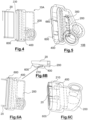
Figure 4 représente une vue de connecteur qui est prêt à recevoir un tube ; - la
Figure 5 représente une vue de connecteur assemblé comportant une agrafe et prêt à recevoir un tube ; - la
Figure 6A représente une vue de connecteur de la présente invention qui reçoit un tube, le tiroir étant dans une première position ; - la
Figure 6B représente une vue en coupe partielle de laFigure 6A ; - la
Figure 6C représente une autre vue de connecteur de la présente invention qui reçoit un tube, le tiroir étant dans une première position ; - la
Figure 7A représente une vue de connecteur de la présente invention ayant reçu un tube, le tiroir étant dans une deuxième position ; - la
Figure 7B représente une vue en coupe partielle de laFigure 7A ; - la
Figure 7C représente une autre vue de connecteur de la présente invention ayant reçu un tube, le tiroir étant dans une deuxième position ; - la
Figure 8A représente une vue en coupe de laFigure 6C ; - la
Figure 8B représente une vue en coupe de laFigure 7C ; - la
Figure 9A représente une vue en perspective d'un groupe de cellules cylindriques dont les tubes de gestion thermique sont reliés par des connecteurs selon la présente invention ; - la
Figure 9B représente une vue partielle du groupe de lafigure 9A avec deux connecteurs à monter ; - la
Figure 10A représente une vue de dessus d'un connecteur selon un mode de réalisation ayant reçu un tube ; - la
Figure 10B représente une vue en coupe du dispositif de laFigure 10A ; - la
Figure 10C représente une autre vue en coupe du dispositif de laFigure 10A ; - la
Figure 11 représente une vue de dessus de connecteurs liés ayant tous reçu un tube. - Les différentes figures ainsi que les éléments d'une même figure ne sont pas nécessairement représentées à la même échelle. Sur l'ensemble des figures, les éléments identiques portent la même référence numérique.
- La terminologie employée dans la présente description ne doit en aucun cas être interprétée de manière limitative ou restrictive, simplement parce qu'elle est employée en conjonction avec une description détaillée de certains modes de réalisation de l'invention.
- La
Figure 1A montre une vue en perspective d'un connecteur 10A selon un mode de réalisation de la présente invention. Le connecteur 10A comprend une tête 200, un tiroir 600 et une bague de joint 400. La tête 200 comporte un logement 230 apte à recevoir une première extrémité 602 du tiroir. Le tiroir 600 est muni d'un orifice de passage et apte à recevoir un tube par une deuxième extrémité 604. En état de fonctionnement, la bague de joint 400 est disposée entre la tête et le tiroir. - Dans un mode de réalisation préféré, le tube 20 est un tube à mini canaux et/ou micro-canaux (Micro Port Extrusion ou MPE ou miltiport flat tube).
- La
Figure 1B montre une vue en perspective d'un connecteur 10B selon un autre mode de réalisation. Outre la tête 200, le tiroir 600 et une bague de joint 400, le connecteur 10B comporte avantageusement une agrafe 300. Comme on le verra par la suite, l'agrafe 300 permet de retenir davantage un tube qui est inséré dans le connecteur 10B. Avantageusement, l'agrafe 300 est métallique. - La
Figure 2 montre une vue en éclaté du connecteur 10B ayant une agrafe 300 qui est prêt à connecter à un tube 20. En mode fonctionnement, le tiroir 600 est reçu dans le logement 230 de la tête 200. Le tube 20 passe à travers de l'orifice de passage 620 et de la bague de joint 400. Le tube est reçu par l'agrafe 300 se trouvant au fond du logement 230. Une extrémité du tube 20 est retenue par l'agrafe 300 qui est lui-même retenue par une paroi interne du logement 230 de la tête. - Avantageusement, l'agrafe 300 présente une section en « U » et définit un espace intérieur destiné à recevoir une extrémité du tube 20. L'agrafe 300 comporte avantageusement des moyens de retenue intérieurs, comme patte intérieure 340 ou contre dépouille, pour retenir le tube. L'agrafe 300 comporte également des moyens de retenue extérieurs, comme patte extérieure 360 ou contre dépouille, permettant être retenue par la tête 200 dans le logement 230. Avantageusement, l'agrafe 300 est disposée entre la bague de joint 400 et la tête 200. Le tube 20 passe à travers de la bague de joint et puis est retenu par l'agrafe 300. Ceci permet d'éviter l'endommagement de la bague de joint par l'agrafe.
- Sur la
Figure 3A , on observe la tête 200 du connecteur, qui comporte un corps 210 apte à recevoir le tiroir 600 avec son logement 230. - La tête 200 comporte avantageusement un embout 280 qui permet d'intégrer la tête 200 dans un réseau de circulation de fluide, tel qu'un fluide caloporteur. Avantageusement, ceci permet un montage rapide du connecteur dans un système de gestion thermique. De plus, le connecteur est démontable du système de gestion thermique et donc réutilisable.
- Dans un mode de réalisation préféré, la tête comporte un embout mâle 280A et un embout femelle 280B, ce qui permet aux têtes 200 de se connecter entre elles directement ou via des adaptateurs.
- Avantageusement, aucune pièce de connexion est nécessaire pour lier directement des connecteurs et former un passage de circulation.
- Dans un mode de réalisation préféré, la tête 200 est munie d'une cavité de forme triangulaire ou trapézoïdale 270, comme on le verra plus loin.
- La
Figure 3B représente un mode de réalisation préféré dans lequel le tiroir 600 est solidarisé à la bague de joint 400. Il est particulièrement avantageux, car ceci permet de poser la bague de joint 400 dans le logement 230 tout en gardant sa forme. Dans un mode de réalisation préféré, le tiroir 600 et la bague de joint 400 sont surmoulé. - Selon un mode de réalisation non illustré, le tiroir 600 et la bague de joint 400 sont deux pièces séparées. La bague de joint peut être préposée sur le tiroir 600 avant qu'il soit inséré dans le logement 230.
- Dans un mode de réalisation, la bague de joint 400, indépendamment du tiroir 600, peut être introduite dans le logement 230 de la tête 200.
- Le tiroir 600 comporte un premier élément de blocage 640, tel qu'une contre dépouille, qui peut coopérer avec le premier moyen de fixation 220 de la tête, tel qu'une fenêtre, pour former un premier moyen de fixation mécanique, tel qu'une connexion par encliquetage. Avantageusement, ceci permet de maintenir le tiroir dans une première position au sein du logement 230 de la tête. Dans cette première position, le tiroir 600 est préassemblé dans la tête. Le tiroir 600 comporte un deuxième élément de blocage 660, tel qu'une contre dépouille, qui peut coopérer avec le deuxième moyen de fixation 240 de la tête, tel qu'une fenêtre, pour former un deuxième moyen de fixation mécanique, tel qu'une connexion par encliquetage. Avantageusement, ceci permet de maintenir le tiroir dans une deuxième position au sein du logement 230 de la tête.
- Avantageusement, la tête 200 comporte ouverture permettant de recevoir un outil pour dégager le tiroir 600 dans la première position et/ou la deuxième position. En d'autres termes, le connecteur est démontrable à l'aide d'un simple outil.
- Sur la
Figure 4 , on observe un connecteur 10A, dans lequel le tiroir 600 est reçu dans la tête 200 avec la bague de joint 400 disposée entre la tête et le tiroir. Le tiroir 600 se trouve dans une première position, dite position d'assemblage, dans laquelle le tiroir 600 est prêt à recevoir un tube 20 par une extrémité de sorte que le tube 20 passe à travers la bague de joint 400. Dans le mode de réalisation illustré sur laFigure 5 , le connecteur 10B comporte une agrafe 300 se trouvant au fond du logement 230 pour retenir au moins partiellement une section d'extrémité du tube 20. - On introduit ensuite le tube dans le tiroir 600 en le poussant vers la tête 200 jusqu'en butée avec le fond du logement 230. Dans le mode de réalisation illustré sur les
Figures 6A et 6C , le tiroir 600 est dans la première position vis-à-vis de la tête 200. Le tube 20 passe à travers de la bague de joint 400. Dans un mode de réalisation préféré, la bague de joint 400 n'entre pas en contact avec le tube 20 dans cette première position. Avantageusement, ceci permet d'éviter l'endommagement de la bague de joint 400 par le tube 20 lors de son introduction. - Sur la
Figure 6B , on observe que la bague de joint 400 se trouve entre la paroi latérale du logement 230 et le tube 20, d'une part, et entre le tiroir 600 et le fond du logement 230, d'autre part. - On appuie ensuite le tiroir 600 de sorte qu'il se déplace de la première position à une deuxième position, dite position de travail, dans le logement 230. Dans cette deuxième position, la bague de joint 400 est compressée ou déformée par le tiroir 600. Les
Figures 7A et 7C illustrent cette position de travail. Comme illustré sur laFigure 6B , la bague de joint 400 est prise en sandwich entre le tiroir 600 et une paroi interne du logement 230 dans la deuxième position. - Dans un mode de réalisation préféré, la tête 200 est complétée par une cavité de forme triangulaire ou trapézoïdale 270. Le fluide qui sort du tube 20 entre dans la cavité de forme triangulaire ou trapézoïdale de la tête 200 avant de sortir par l'embout 280. Avantageusement, ceci permet d'atténuer la pression hydraulique exercée par le fluide dans le connecteur et le tube.
- Dans un mode de réalisation, la tête comporte des moyens de contrôle visuel permettant de vérifier l'état d'assemblage entre la tête et le tiroir, par exemple une fenêtre de contrôle.
- Avantageusement, la bague de joint 400 est un anneau d'étanchéité compressible et présente une forme simple d'anneau.
- Avantageusement, la bague de joint présente une forme qui adapte à la section du tube 20 et à la paroi du logement 230.
- Dans un mode de réalisation préféré, la bague de joint 400 est avantageusement réalisée en matériau élastomère.
- En état compressé, la bague de joint 400 entre en contact avec la surface du tube 20, ceci permettant d'assurer l'étanchéité entre le tube et la bague de joint. Encore avantageusement, la bague de joint 400 compressée par le tiroir 600 assure une préhension mécanique avec le tube qui est retenu dans le connecteur malgré la pression du fluide.
- Avantageusement, la bague de joint 400 est de matériau adapté qui permet de résiste à la différence de pression du fluide.
- La
Figure 8A représente une vue en coupe de laFigure 6C . S1 signifie le sens de circulation de fluide dans le tube 20. Le fluide peut circuler également dans le sens inverse. Le tiroir 600 logé dans la tête 200 se trouve dans la première position. La tête 200 comporte avantageusement un orifice moins large dans la continuité du logement 230. Cet orifice fait partie du réseau de circulation de fluide. On pourra ensuite appuyer le tube 20 inséré dans l'orifice de passage du tiroir jusqu'en butée. - Dans un mode de réalisation, le tube 20 est encastré dans l'orifice de la tête.
- La
Figure 8B représente une vue en coupe de laFigure 7C . S2 signifie le sens de force de poussée appliquée sur le tiroir 600 pour qu'il se déplace dans la deuxième position. - Avantageusement, le fait que le tiroir 600 entre dans sa deuxième position donne à l'opérateur une sensation de clippage.
- La bague de joint 400 prise en sandwich entre le tiroir 600 et une paroi du logement 230 se déforme en deuxième position, de sorte à créer une interférence avec la paroi du logement 230 et avec la surface externe du tube 20. La présence de référence assure avantageusement l'étanchéité des différentes interfaces. Avantageusement, le tube 20 présente une surface extérieure rigide. Ceci permet de renforcer l'étanchéité obtenue. Avantageusement, ceci permet de réduire la force d'assemblage, plus particulièrement la force pour introduire le tube, car la bague de joint est compressée par le tiroir après l'introduction du tube 20 dans le connecteur. Cette déformation élastique assure l'étanchéité de contact au niveau du plan de joint.
- Avantageusement, la déformation de la bague de joint permet d'augmenter la pression de contact entre la bague de joint et le tube.
- Dans un mode de réalisation non illustré, la bague de joint 400 est munie de deux lèvres 420 de retenue sur sa surface interne. Ceci permet d'obtenir une meilleure étanchéité et/ou une meilleure préhension mécanique vis-à-vis du tube 20. La bague de joint peut comporter encore plus de lèvres de retenue sur sa surface interne.
- La
Figure 9A représente une vue en perspective d'un groupe de batteries cylindriques 30 intégrées dans un système de gestion thermique dont les tubes 20 de gestion thermique sont reliés aux connecteurs 10A, 10B selon la présente invention. Avantageusement, le tube 20 présente au moins une surface ondulée qui est en contact avec des objets à refroidir tels que des batteries prismatiques 30. Le système de gestion thermique comporte en outre une entrée 2 et une sortie 4 commune. - Dans un mode de réalisation non illustré, le tube 20 présente avantageusement au moins une surface plane qui est en contact avec des objets à refroidir tels que des batteries de type «pouch», cylindriques, prismatiques.
- La
Figure 9B montre une vue partielle du groupe de batteries de lafigure 9A . - Avantageusement, l'embout mâle 280A et l'embout femelle 280B permettent aux connecteurs de se relier et de s'intégrer dans le système de gestion thermique.
- Les
Figures 10A-10C illustrent un variant d'un connecteur selon la présente invention. Ce connecteur peut reprendre toutes les caractéristiques d'un connecteur présenté auparavant dans cette divulgation. - Sur la
Figure 10A , on observe une vue de dessus d'un connecteur 10C selon ce mode de réalisation ayant reçu un tube 20. - La tête 100 comporte un embout sur le même plan de la tête 100. Avantageusement, la tête 100 est munie, sur le même plan que la tête, de deux embouts opposés, ceci permettant aux connecteurs de se relier directement ou via un adaptateur.
- On observe sur la
Figure 10B une vue en coupe d'un connecteur selon ce mode de réalisation. Le tiroir 600 se trouve dans la deuxième position avec la bague de joint 400 compressée prise en sandwich entre le tiroir et une paroi du logement. - La
Figure 10C représente une autre vue en coupe d'un connecteur 10C de laFigure 10A qui comporte en outre une agrafe 300. Le tube 20 est retenu par l'agrafe 300 dans cette position. - La
Figure 11 représente une vue en perspective d'un groupe de batteries prismatiques 30A intégrées dans un système de gestion thermique. - On observe sur la
Figure 11 une partie d'un système de gestion thermique dans lequel des connecteurs 10C sont interconnectés et sont connectés aux tubes 20. - Dans un mode de réalisation non illustré, les connecteurs 10C sont interconnectés via un adaptateur.
-
[Tableaux 1] Références Désignations 10A ;10B ;10C Connecteur 20 Tube 22 Canal 30 Batterie (cellule cylindrique) 30A Batterie (cellule prismatique) 100 Tête 200 Tête 210 Corps 220 Premier moyen de fixation 230 Logement 240 Deuxième moyen de fixation 260 Moyens de contrôle visuel 270 Partie triangulaire ou trapézoïdale 280 Embout 280A Embout mâle 280B Embout femelle 300 Agrafe 320 Espace interne 340 Patte intérieure 360 Patte extérieure 400 Bague de joint 420 Lèvre de retenue 600 Tiroir 602 Première extrémité 604 Deuxième extrémité 640 Premier élément de blocage 660 Deuxième élément de blocage
Claims (17)
- Connecteur (10A; 10B; 10C) pour connecter à un tube (20), comprenant une tête (200), un tiroir (600) muni d'un orifice de passage (620), et une bague de joint (400) disposée entre la tête et le tiroir, la tête (200) comportant un logement (230) apte à recevoir une première extrémité (602) du tiroir,
caractérisé en ce que
le tiroir reçu dans le logement (230) comprend :une première position, dite position d'assemblage, dans laquelle le tiroir (200) est apte à recevoir un tube (20) par une deuxième extrémité (604) du tiroir de sorte que le tube passe à travers la bague de joint (400); etune deuxième position, dite position de travail, dans laquelle la bague de joint (400) est susceptible d'être compressée par la première extrémité (602) du tiroir; etque le tiroir (600) se déplace de la première position à la deuxième position sous effet d'une force de poussée. - Connecteur (10B) selon la revendication 1, caractérisé en ce qu'il comprend une agrafe (300) disposée entre la bague de joint (400) et une butée au sein du logement (230) et l'agrafe comprend un espace interne (320) apte à recevoir au moins partiellement une section d'extrémité d'un tube (20).
- Connecteur (10A; 10B; 10C) selon l'une des revendications précédentes, caractérisé en ce que le tiroir (200) est retenu à la tête (200) dans la première position et/ou dans la deuxième position par des moyens de fixation mécanique.
- Connecteur (10A; 10B; 10C) selon l'une des revendications précédentes, caractérisé en ce que le tiroir (200) est retenu à la tête (200) dans la première position et/ou dans la deuxième position par une connexion à encliquetage.
- Connecteur (10A; 10B; 10C) selon l'une des revendications précédentes, dans lequel la bague de joint (400) est un anneau d'étanchéité.
- Connecteur (10A; 10B; 10C) selon l'une des revendications précédentes, dans lequel la bague de joint (400) est prise en sandwich entre le tiroir (600) et une paroi du logement (230) lorsque le tiroir (600) se trouve dans la deuxième position.
- Connecteur (10A; 10B; 10C) selon l'une des revendications précédentes, dans lequel la bague de joint (400) comprend au moins deux lèvres de retenue (420) sur sa surface intérieure.
- Connecteur (10A; 10B; 10C) selon l'une des revendications précédentes, dans lequel le tiroir (600) et la bague de joint (400) sont surmoulés.
- Connecteur (10A; 10B; 10C) selon l'une des revendications précédentes, dans lequel la tête (200) comporte une ouverture permettant de recevoir un outil pour dégager le tiroir (600) dans la première position et/ou la deuxième position.
- Connecteur (10A; 10B; 10C) selon l'une des revendications précédentes, dans lequel la tête (200) comporte une cavité de forme triangulaire ou trapézoïdale dans la continué du logement (230).
- Connecteur (10A; 10B; 10C) selon l'une des revendications précédentes, dans lequel la tête (200) comporte des moyens de contrôle visuel permettant de vérifier l'état d'assemblage entre la tête (200) et le tiroir (600).
- Ensemble d'un connecteur selon l'une des revendications 1 à 11 et un tube reçu dans le tiroir (600).
- Ensemble selon la revendication 12, caractérisé en ce que, dans la deuxième position, la bague de joint (400) compressée par le tiroir (600) assure une étanchéité entre la tête (200) et le tube (20).
- Ensemble selon la revendication 12 ou 13, caractérisé en ce que, dans la deuxième position, la bague de joint (400) compressée par le tiroir (600) assure une préhension mécanique avec le tube (20).
- Ensemble selon la revendication 12 à 14, caractérisé en ce que, le tube est un tube à micro-canaux comportant d'au moins une surface plane.
- Ensemble selon la revendication 12 à 14, caractérisé en ce que, le tube est un tube à micro-canaux comportant d'au moins une surface ondulée.
- Ensemble selon l'une des revendications 12 à 16, caractérisé en ce que, dans la deuxième position, la bague de joint (400) compressée par le tiroir (600) interfère avec une paroi intérieure du logement (230).
Applications Claiming Priority (1)
| Application Number | Priority Date | Filing Date | Title |
|---|---|---|---|
| FR2207144A FR3137954B1 (fr) | 2022-07-12 | 2022-07-12 | Connecteur |
Publications (1)
| Publication Number | Publication Date |
|---|---|
| EP4306895A1 true EP4306895A1 (fr) | 2024-01-17 |
Family
ID=83280272
Family Applications (1)
| Application Number | Title | Priority Date | Filing Date |
|---|---|---|---|
| EP23183191.8A Pending EP4306895A1 (fr) | 2022-07-12 | 2023-07-04 | Connecteur |
Country Status (4)
| Country | Link |
|---|---|
| US (1) | US12498185B2 (fr) |
| EP (1) | EP4306895A1 (fr) |
| CN (1) | CN117386913A (fr) |
| FR (1) | FR3137954B1 (fr) |
Families Citing this family (2)
| Publication number | Priority date | Publication date | Assignee | Title |
|---|---|---|---|---|
| EP4603319A1 (fr) * | 2024-02-15 | 2025-08-20 | Borgwarner Emissions Systems Spain, S.L.U. | Support de manipulation pour plaques de conduction thermique d'éléments de batterie |
| FR3161310A1 (fr) * | 2024-04-16 | 2025-10-17 | Valeo Systemes Thermiques | Dispositif de régulation thermique, notamment de refroidissement pour véhicule automobile. |
Citations (3)
| Publication number | Priority date | Publication date | Assignee | Title |
|---|---|---|---|---|
| US20170343144A1 (en) * | 2016-05-31 | 2017-11-30 | Mitchell W. Hunt | Fluid Connector Assembly |
| WO2020187612A1 (fr) | 2019-03-15 | 2020-09-24 | Hydro Extruded Solutions As | Raccordement d'extrusion à orifices multiples (mpe) à une embase |
| EP3885689A1 (fr) * | 2020-03-26 | 2021-09-29 | A. Raymond et Cie | Connecteur conçu pour être connecté à un tube extrudé à ports multiples |
Family Cites Families (12)
| Publication number | Priority date | Publication date | Assignee | Title |
|---|---|---|---|---|
| US3591204A (en) * | 1968-05-07 | 1971-07-06 | Fmc Corp | Underwater flow line connector system |
| US5170841A (en) * | 1989-03-15 | 1992-12-15 | Hutchinson | Multi-way quick action coupling device particularly for motor vehicle engine cooling circuits |
| US20030131981A1 (en) * | 2002-01-15 | 2003-07-17 | Kohler Gregory T. | Tank and cap assembly for use with microchannel tubing in a heat exchanger |
| US10765043B2 (en) * | 2016-01-04 | 2020-09-01 | Lisa Draexlmaier Gmbh | Heat exchanger for an electrical component in a motor vehicle and production method |
| CN106992273B (zh) * | 2016-09-21 | 2018-09-11 | 比亚迪股份有限公司 | 动力电池包 |
| US10975993B2 (en) * | 2017-08-11 | 2021-04-13 | Norma U.S. Holding Llc | Fluid line connector and assembly with securement detection |
| FR3084699B1 (fr) * | 2018-07-31 | 2020-09-25 | Safran Aircraft Engines | Echangeur thermique pour turbomachine et procede de fabrication associe |
| KR102748301B1 (ko) * | 2019-08-27 | 2024-12-27 | 주식회사 엘지에너지솔루션 | 커넥터 |
| JP7750171B2 (ja) * | 2022-05-11 | 2025-10-07 | 株式会社オートネットワーク技術研究所 | コネクタ及びコネクタの製造方法 |
| US20240405332A1 (en) * | 2023-05-30 | 2024-12-05 | GM Global Technology Operations LLC | Hollow prismatic and cylindrical battery cells, method for manufacturing, and battery heat exchange system |
| CN116780020A (zh) * | 2023-06-20 | 2023-09-19 | 厦门海辰储能科技股份有限公司 | 电池包和储能设备 |
| US20250062465A1 (en) * | 2023-08-14 | 2025-02-20 | GM Global Technology Operations LLC | Double-walled enclosure and/or cooling system for prismatic battery cells |
-
2022
- 2022-07-12 FR FR2207144A patent/FR3137954B1/fr active Active
-
2023
- 2023-07-04 EP EP23183191.8A patent/EP4306895A1/fr active Pending
- 2023-07-11 CN CN202310845650.5A patent/CN117386913A/zh active Pending
- 2023-07-11 US US18/350,178 patent/US12498185B2/en active Active
Patent Citations (4)
| Publication number | Priority date | Publication date | Assignee | Title |
|---|---|---|---|---|
| US20170343144A1 (en) * | 2016-05-31 | 2017-11-30 | Mitchell W. Hunt | Fluid Connector Assembly |
| WO2020187612A1 (fr) | 2019-03-15 | 2020-09-24 | Hydro Extruded Solutions As | Raccordement d'extrusion à orifices multiples (mpe) à une embase |
| CN113544459A (zh) * | 2019-03-15 | 2021-10-22 | 水力挤压解决方案股份公司 | 多端口挤压件(mpe)与集管的连接件 |
| EP3885689A1 (fr) * | 2020-03-26 | 2021-09-29 | A. Raymond et Cie | Connecteur conçu pour être connecté à un tube extrudé à ports multiples |
Also Published As
| Publication number | Publication date |
|---|---|
| US12498185B2 (en) | 2025-12-16 |
| CN117386913A (zh) | 2024-01-12 |
| FR3137954B1 (fr) | 2024-10-04 |
| US20240019220A1 (en) | 2024-01-18 |
| FR3137954A1 (fr) | 2024-01-19 |
Similar Documents
| Publication | Publication Date | Title |
|---|---|---|
| FR3066264B1 (fr) | Echangeur thermique, notamment pour la regulation thermique de batteries, et procede de fabrication correspondant | |
| FR3137954A1 (fr) | Connecteur | |
| EP3350420A1 (fr) | Interface et dispositif de support pour carter moteur | |
| EP3461297B1 (fr) | Dispositif de refroidissement de batteries et procede de fabrication correspondant | |
| EP2210054A1 (fr) | Dispositif de refroidissement d'un fluide caloporteur | |
| WO2020254757A1 (fr) | Echangeur thermique a circulation de liquide et connecteur pour un tel échangeur | |
| EP2871436A1 (fr) | Echangeur de chaleur comprenant un faisceau d'echange connecte a deux extremites opposees aux parois du boitier | |
| FR3107331A1 (fr) | dispositif de circulation de fluide, son procédé de montage, ainsi qu’un ensemble comprenant un tel dispositif de circulation de fluide | |
| FR3015015A1 (fr) | Echangeur de chaleur comprenant un faisceau muni de moyens permettant de limiter les mouvements dudit faisceau d'echange par rapport aux parois du boitier | |
| EP3001132B1 (fr) | Procédé de fabrication d'un échangeur de chaleur | |
| FR3039263B1 (fr) | Echangeur de chaleur comprenant un boitier et des moyens pour ameliorer l'etancheite dudit boitier | |
| WO2020260795A1 (fr) | Dispositif refroidisseur d'un ou plusieurs modules de stockage d'energie electrique | |
| EP4306894A1 (fr) | Boîte collectrice et système de gestion thermique comportant une telle boîte collectrice | |
| FR3077129A1 (fr) | Boite collectrice pour un echangeur thermique, notamment pour la regulation thermique de batteries, echangeur thermique et procede de fabrication correspondant | |
| EP3022511B1 (fr) | Échangeur de chaleur avec un bloc d'adaptation fixé sur une plaque d'extrémité, et procédé de fabrication associé | |
| EP3830403A1 (fr) | Echangeur thermique pour turbomachine et procede de fabrication associe | |
| FR3077127A1 (fr) | Echangeur thermique, notamment pour la regulation thermique de batteries | |
| EP3830401B1 (fr) | Échangeur thermique pour turbomachine | |
| WO2004013936A1 (fr) | Dispositif de retention de contact ameliore | |
| FR3094471A1 (fr) | Interface et ensemble de raccordement de tubulures de fluide réfrigérant dans un ensemble de refroidissement d’un dispositif de stockage électrique | |
| FR2868522A1 (fr) | Module d'echange de chaleur, en particulier pour vehicules automobiles | |
| WO2024028092A2 (fr) | Dispositif de regulation thermique pour le refroidissement d'organes de stockage d'energie electrique | |
| FR3082589A1 (fr) | Raccord rapide compact pour fluide comprenant un clapet anti-retour | |
| FR3139046A1 (fr) | Assemblage comportant un module de refroidissement | |
| FR2935553A1 (fr) | Adaptateur modulaire pour insert de connecteur, et ensemble de connexion comportant de tels adaptateurs modulaires |
Legal Events
| Date | Code | Title | Description |
|---|---|---|---|
| PUAI | Public reference made under article 153(3) epc to a published international application that has entered the european phase |
Free format text: ORIGINAL CODE: 0009012 |
|
| STAA | Information on the status of an ep patent application or granted ep patent |
Free format text: STATUS: THE APPLICATION HAS BEEN PUBLISHED |
|
| AK | Designated contracting states |
Kind code of ref document: A1 Designated state(s): AL AT BE BG CH CY CZ DE DK EE ES FI FR GB GR HR HU IE IS IT LI LT LU LV MC ME MK MT NL NO PL PT RO RS SE SI SK SM TR |
|
| STAA | Information on the status of an ep patent application or granted ep patent |
Free format text: STATUS: REQUEST FOR EXAMINATION WAS MADE |
|
| 17P | Request for examination filed |
Effective date: 20240715 |
|
| RBV | Designated contracting states (corrected) |
Designated state(s): AL AT BE BG CH CY CZ DE DK EE ES FI FR GB GR HR HU IE IS IT LI LT LU LV MC ME MK MT NL NO PL PT RO RS SE SI SK SM TR |