EP4306892A1 - Heat exchanger channel - Google Patents
Heat exchanger channel Download PDFInfo
- Publication number
- EP4306892A1 EP4306892A1 EP22461580.7A EP22461580A EP4306892A1 EP 4306892 A1 EP4306892 A1 EP 4306892A1 EP 22461580 A EP22461580 A EP 22461580A EP 4306892 A1 EP4306892 A1 EP 4306892A1
- Authority
- EP
- European Patent Office
- Prior art keywords
- section
- channel
- fluid
- heat exchanger
- twisted
- Prior art date
- Legal status (The legal status is an assumption and is not a legal conclusion. Google has not performed a legal analysis and makes no representation as to the accuracy of the status listed.)
- Pending
Links
Images


Classifications
-
- F—MECHANICAL ENGINEERING; LIGHTING; HEATING; WEAPONS; BLASTING
- F28—HEAT EXCHANGE IN GENERAL
- F28F—DETAILS OF HEAT-EXCHANGE AND HEAT-TRANSFER APPARATUS, OF GENERAL APPLICATION
- F28F1/00—Tubular elements; Assemblies of tubular elements
- F28F1/02—Tubular elements of cross-section which is non-circular
- F28F1/025—Tubular elements of cross-section which is non-circular with variable shape, e.g. with modified tube ends, with different geometrical features
-
- F—MECHANICAL ENGINEERING; LIGHTING; HEATING; WEAPONS; BLASTING
- F28—HEAT EXCHANGE IN GENERAL
- F28D—HEAT-EXCHANGE APPARATUS, NOT PROVIDED FOR IN ANOTHER SUBCLASS, IN WHICH THE HEAT-EXCHANGE MEDIA DO NOT COME INTO DIRECT CONTACT
- F28D7/00—Heat-exchange apparatus having stationary tubular conduit assemblies for both heat-exchange media, the media being in contact with different sides of a conduit wall
- F28D7/0008—Heat-exchange apparatus having stationary tubular conduit assemblies for both heat-exchange media, the media being in contact with different sides of a conduit wall the conduits for one medium being in heat conductive contact with the conduits for the other medium
-
- F—MECHANICAL ENGINEERING; LIGHTING; HEATING; WEAPONS; BLASTING
- F28—HEAT EXCHANGE IN GENERAL
- F28F—DETAILS OF HEAT-EXCHANGE AND HEAT-TRANSFER APPARATUS, OF GENERAL APPLICATION
- F28F1/00—Tubular elements; Assemblies of tubular elements
- F28F1/02—Tubular elements of cross-section which is non-circular
- F28F1/04—Tubular elements of cross-section which is non-circular polygonal, e.g. rectangular
Definitions
- the present disclosure is concerned with channels for the flow of fluid in a heat exchanger, and specifically channels made by additive manufacturing.
- Heat exchangers typically work by the transfer of heat between fluid flowing in parallel channels defined by metal plates of a heat exchanger core.
- a heat exchanger core is generally in the form of a block made up of layers of plates which define the channels through which the fluid flows. The channels are arranged such that hot fluid flows through some channels and cold fluid flows through other channels with the hot and cold channels arranged either vertically or horizontally adjacent each other such that heat is exchanged across the boundary between the channels. Thermal properties are improved by the introduction of turbulence in the flow channels and so, conventionally, a heat exchanger core comprises corrugated metal plates arranged adjacent each other so as to define corrugated flow channels for the heat exchange fluids.
- AM additive manufacture
- 3D printing has recently become a preferred manufacturing method for many parts and components due to the fact that it is relatively quick and low cost and allows for great flexibility in the design of new components and parts. Due to the fact that components and parts made by additive manufacture (AM) can be quickly made in a custom designed form, as required, AM also brings benefits in that stocks of components do not need to be manufactured and stored to be available as needed. AM parts can be made of relatively light, but strong materials. As AM is becoming more popular in many industries, there is interest in manufacturing heat exchangers using AM.
- a channel for a heat exchanger through which heat exchange fluid flow will flow, in use, the channel comprising an elongate tubular channel body extending along an axis A from a first end to a second end, the channel body having walls, the interior surface of which define an interior channel through which heat exchanger fluid flows from the first end to the second end, and wherein the channel body comprises two or more straight sections having a constant cross section in which the interior channel has a rectangular, square or triangular cross-section, and a twisted section between the or each pair of adjacent straight sections, in the axial direction, the twisted section being a section resulting from one of the straight sections twisted about the axis A with respect to an adjacent straight section, wherein at the twisted section the interior channel has a cross-section different from the cross section at the adjacent straight section, thus creating a swirl effect on fluid flowing through the interior channel.
- a heat exchanger comprises a plurality of fluid flow channels defined between layers of metal plates and through which heat exchange fluids flow.
- the fluids are provided to the core of plates and channels via a manifold such that a relatively cold fluid flows through some of the channels and a relatively hot fluid flows through others of the channels.
- the channels are arranged such that their outer walls are in contact with outer walls of other channels such that heat exchange takes place across the adjacent channel walls due to the different temperature of the fluids flowing through the channels.
- the channels have been formed by corrugated sheets with the corrugations forming the channels. With the advent of additive manufacturing techniques, however, it has become possible to form channels of different shapes and/or as discrete tubular elements that are assembled side-by-side to form the heat exchanger core.
- Tubular channels may be, for example, in the form of a rectangular cross-section tube or a triangular cross-section tube.
- the convective heat transfer coefficient can be improved by introducing turbulence in the flow through the channel.
- creating turbulence avoids creation of the insulating boundary layer at the channel walls, as mentioned above.
- the increasing use of additive manufacturing has made it possible to create channels having features that increase turbulence in the flow.
- Additive manufacturing of channels does, however, bring its own limitations in that there is a limitation of channel size due to the required post-printing powder removal. It is often desired to create designs with features inside the channels but which have limited impact on the cross-sectional area of the channel to avoid the accumulation of powder, and it is not easy to incorporate additional devices for causing swirl of the fluid as it travels through the channel into the interior of the channel within such constraints.
- the channel according to this disclosure is formed using additive manufacture and so is limited in size, but is structured to provide a swirl effect that does not reduce the cross-sectional area of the channel, or only reduces the cross section by a limited amount and so does not hinder powder removal or flow of fluid, but does increase turbulence of the fluid flowing through the channel.
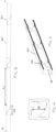
- the channel according to this disclosure, an example of which is shown in various views in Figs. 1 to 4 , comprises an elongate tubular channel body 10 extending along an axis A from a first end 11 to a second end 12.
- the channel body defines an interior channel 14 through which heat exchanger fluid flows from the first end 14a to the second end 14b, and wherein the body comprises two or more straight sections 20 having a constant cross section wherein the interior channel has a rectangular, square or triangular cross-section, and a twisted section 30 between the or each pair of adjacent straight sections, in the axial direction, the twist section being a section resulting from one of the straight sections twisted substantially 90 degrees (for a square channel) or 180 degrees for a rectangular channel or 60 degrees for a triangular channel with respect to the adjacent straight section, wherein at the twist section the interior channel has a cross-section 32 different from the cross section at the straight section, thus creating a swirl effect on fluid flowing through the channel.
- the channel will be formed with several twist sections 30, each adding a further 90/180/60 degree twist of the channel body. After each twist, then, the cross-section of the straight section 20 is aligned with that of the previous straight section, before the twist.
- twists between straight sections thus cause an interruption in the straight channel for the fluid flowing through the channel.
- the channel is made, as mentioned above, by additive manufacturing or 3D printing.
- the length L2 of the twist section (essentially the pitch of the run) can also be varied as desired. The lengths can be varied to vary the intensity of the swirl effect.
- the swirl effect of the twists can be seen in Fig. 5 .
- Fluid initially flows along a straight section and then hits a twist section whereupon the fluid is subjected to a swirl effect changing its velocity. This is followed by a straight channel and, depending on the length and design of the channel, subsequent twist sections.
- the swirl has the effect of disrupting the boundary layer at the channel inner surface due to the changes in surface geometry. The resulting boundary layer is therefore much thinner than the boundary layer that results in straight channels, thus resulting in improved heat transfer.
- a plurality of such channels 10 can be assembled into a block to form a core 100 of a heat exchanger.
- all channels have the same design. It is also feasible that channels of different designs could be used in the core.
Landscapes
- Engineering & Computer Science (AREA)
- Physics & Mathematics (AREA)
- Thermal Sciences (AREA)
- Mechanical Engineering (AREA)
- General Engineering & Computer Science (AREA)
- Geometry (AREA)
- Heat-Exchange Devices With Radiators And Conduit Assemblies (AREA)
Abstract
Description
- The present disclosure is concerned with channels for the flow of fluid in a heat exchanger, and specifically channels made by additive manufacturing.
- Heat exchangers typically work by the transfer of heat between fluid flowing in parallel channels defined by metal plates of a heat exchanger core. A heat exchanger core is generally in the form of a block made up of layers of plates which define the channels through which the fluid flows. The channels are arranged such that hot fluid flows through some channels and cold fluid flows through other channels with the hot and cold channels arranged either vertically or horizontally adjacent each other such that heat is exchanged across the boundary between the channels. Thermal properties are improved by the introduction of turbulence in the flow channels and so, conventionally, a heat exchanger core comprises corrugated metal plates arranged adjacent each other so as to define corrugated flow channels for the heat exchange fluids.
- Additive manufacture, or 3D printing, has recently become a preferred manufacturing method for many parts and components due to the fact that it is relatively quick and low cost and allows for great flexibility in the design of new components and parts. Due to the fact that components and parts made by additive manufacture (AM) can be quickly made in a custom designed form, as required, AM also brings benefits in that stocks of components do not need to be manufactured and stored to be available as needed. AM parts can be made of relatively light, but strong materials. As AM is becoming more popular in many industries, there is interest in manufacturing heat exchangers using AM.
- In conventional heat exchanger channels, the viscous fluids that are commonly used create a thick boundary layer at the walls of the channels. This boundary layer presents a resistance to heat exchange across the channel walls and reduces the amount of energy that can be transferred through the channel wall by heat exchange. Additive manufacturing provides the opportunity to create new shapes of heat exchanger channel to address this problem.
- According to this disclosure there is provided a channel for a heat exchanger, through which heat exchange fluid flow will flow, in use, the channel comprising an elongate tubular channel body extending along an axis A from a first end to a second end, the channel body having walls, the interior surface of which define an interior channel through which heat exchanger fluid flows from the first end to the second end, and wherein the channel body comprises two or more straight sections having a constant cross section in which the interior channel has a rectangular, square or triangular cross-section, and a twisted section between the or each pair of adjacent straight sections, in the axial direction, the twisted section being a section resulting from one of the straight sections twisted about the axis A with respect to an adjacent straight section, wherein at the twisted section the interior channel has a cross-section different from the cross section at the adjacent straight section, thus creating a swirl effect on fluid flowing through the interior channel.
- Also provided is a heat exchanger, and a method of manufacturing a channel for a heat exchanger.
- Examples of heat exchanger channels and methods of making them, according to the disclosure, will be described with reference to the drawings. It should be noted that variations are possible within the scope of the claims.
-
Figure 1 is a three dimensional view of an example of a channel according to the disclosure. -
Figure 2 is a side view of a channel such as shown inFig. 1 . -
Figure 3 shows a section of the channel ofFig. 1 . -
Figure 4 is an end view of a channel such as shown inFig. 1 . -
Figure 5 shows the effect of the channel design on fluid flow through the channel. -
Figure 6 shows an example of a heat exchanger core having such channels. - Typically, a heat exchanger comprises a plurality of fluid flow channels defined between layers of metal plates and through which heat exchange fluids flow. The fluids are provided to the core of plates and channels via a manifold such that a relatively cold fluid flows through some of the channels and a relatively hot fluid flows through others of the channels. The channels are arranged such that their outer walls are in contact with outer walls of other channels such that heat exchange takes place across the adjacent channel walls due to the different temperature of the fluids flowing through the channels. As mentioned above, conventionally, the channels have been formed by corrugated sheets with the corrugations forming the channels. With the advent of additive manufacturing techniques, however, it has become possible to form channels of different shapes and/or as discrete tubular elements that are assembled side-by-side to form the heat exchanger core. Tubular channels may be, for example, in the form of a rectangular cross-section tube or a triangular cross-section tube.
- It is known that the convective heat transfer coefficient can be improved by introducing turbulence in the flow through the channel. In particular, creating turbulence avoids creation of the insulating boundary layer at the channel walls, as mentioned above. Again, the increasing use of additive manufacturing has made it possible to create channels having features that increase turbulence in the flow.
- Additive manufacturing of channels does, however, bring its own limitations in that there is a limitation of channel size due to the required post-printing powder removal. It is often desired to create designs with features inside the channels but which have limited impact on the cross-sectional area of the channel to avoid the accumulation of powder, and it is not easy to incorporate additional devices for causing swirl of the fluid as it travels through the channel into the interior of the channel within such constraints.
- The channel according to this disclosure is formed using additive manufacture and so is limited in size, but is structured to provide a swirl effect that does not reduce the cross-sectional area of the channel, or only reduces the cross section by a limited amount and so does not hinder powder removal or flow of fluid, but does increase turbulence of the fluid flowing through the channel.
- The channel according to this disclosure, an example of which is shown in various views in
Figs. 1 to 4 , comprises an elongatetubular channel body 10 extending along an axis A from afirst end 11 to asecond end 12. The channel body defines aninterior channel 14 through which heat exchanger fluid flows from the first end 14a to the second end 14b, and wherein the body comprises two or morestraight sections 20 having a constant cross section wherein the interior channel has a rectangular, square or triangular cross-section, and atwisted section 30 between the or each pair of adjacent straight sections, in the axial direction, the twist section being a section resulting from one of the straight sections twisted substantially 90 degrees (for a square channel) or 180 degrees for a rectangular channel or 60 degrees for a triangular channel with respect to the adjacent straight section, wherein at the twist section the interior channel has across-section 32 different from the cross section at the straight section, thus creating a swirl effect on fluid flowing through the channel. - In practice, the channel will be formed with
several twist sections 30, each adding a further 90/180/60 degree twist of the channel body. After each twist, then, the cross-section of thestraight section 20 is aligned with that of the previous straight section, before the twist. - The twists between straight sections thus cause an interruption in the straight channel for the fluid flowing through the channel.
- The fact that the swirl effect is formed by the channel body - i.e. in the wall of the channel, also means that this effect is actually created at the location where the boundary layer effect is a particular problem.
- The channel is made, as mentioned above, by additive manufacturing or 3D printing. This means that the positions of the twist sections and, hence, the lengths, L1, of the straight section, can be varied as desired, e.g. depending on the flow conditions, temperature, pressure, fluids etc. for the heat exchanger for which the channel is made. The length L2 of the twist section (essentially the pitch of the run) can also be varied as desired. The lengths can be varied to vary the intensity of the swirl effect.
- The swirl effect of the twists can be seen in
Fig. 5 . Fluid initially flows along a straight section and then hits a twist section whereupon the fluid is subjected to a swirl effect changing its velocity. This is followed by a straight channel and, depending on the length and design of the channel, subsequent twist sections. The swirl has the effect of disrupting the boundary layer at the channel inner surface due to the changes in surface geometry. The resulting boundary layer is therefore much thinner than the boundary layer that results in straight channels, thus resulting in improved heat transfer. - As seen, for example, in
Fig. 6 , a plurality ofsuch channels 10 can be assembled into a block to form acore 100 of a heat exchanger. In the example shown, all channels have the same design. It is also feasible that channels of different designs could be used in the core.
Claims (14)
- A fluid flow channel for a heat exchanger, the channel comprising an elongate tubular channel body (10) extending along an axis A from a first end (11) to a second end (12), the channel body (10) having walls, the interior surface of which define an interior channel (14) through which heat exchanger fluid flows from the first end (14a) to the second end (14b), and wherein the channel body (10) comprises two or more straight sections (20) having a constant cross section in which the interior channel has a rectangular, square or triangular cross-section, and a twisted section (30) between the or each pair of adjacent straight sections (20), in the axial direction, the twisted section being a section resulting from one of the straight sections twisted about the axis A with respect to an adjacent straight section, wherein at the twisted section the interior channel has a cross-section (32) different from the cross section at the adjacent straight section, thus creating a swirl effect on fluid flowing through the interior channel.
- A fluid flow channel as claimed in claim 1, wherein the two or more straight sections (20) have a constant rectangular cross-section.
- flow channel as claimed in claim 1, wherein the two or more straight sections (20) have a constant triangular cross-section.
- A fluid flow channel as claimed in claim 1, wherein the two or more straight sections (20) have a constant square cross-section.
- A fluid flow channel as claimed in claim 4, wherein each straight section is twisted at the twist section by 90 degrees with respect to its adjacent straight section.
- A heat exchanger core comprising one or more fluid flow channels as claimed in any preceding claim.
- A heat exchanger core as claimed in claim 6, comprising a plurality of fluid channels arranged adjacent each other to form a block.
- A heat exchanger having a heat exchanger core as claimed in claim 6 or 7.
- A method of forming a fluid flow channel for a heat exchanger using additive manufacture, the method comprising forming a first straight section of am elongate tubular channel body having a channel therethrough with a constant cross-section, creating a twisted section being twisted relative to the first straight section, the twisted section having a cross section different from that of the first straight section, creating a second straight section axially aligned with the first straight section and having a constant cross-section, the twist creating a swirl effect on fluid flowing through the channel.
- A method as claimed in claim 9, wherein each twisted section creates a twist of 90 degrees between a straight section and an adjacent straight section.
- A method of forming a heat exchanger core, comprising forming a plurality of fluid flow channels according to the method of claim 9 or 10, arranging the plurality of fluid flow channels adjacent each other to form a block.
- The method of claim 11, further comprising providing a first fluid inlet, a first fluid outlet, a second fluid inlet and a second fluid outlet, the first fluid inlet and the first fluid outlet connected, respectively, to first and second ends of a first set of the plurality of fluid flow channels and the second fluid inlet and the second fluid outlet connected, respectively, to first and second ends of a second set of the plurality of fluid flow channels.
- The method of claim 12, comprising assembling the first plurality of flow channels adjacent each other in a first layer and the second plurality of fluid flow channels adjacent each other in a second layer.
- The method of claim 12, comprising assembling the first and second plurality of flow channels adjacent each other in a first layer such that each one of the first plurality of fluid flow channels is located between two of the second plurality of fluid flow channels.
Priority Applications (2)
| Application Number | Priority Date | Filing Date | Title |
|---|---|---|---|
| EP22461580.7A EP4306892A1 (en) | 2022-07-13 | 2022-07-13 | Heat exchanger channel |
| US18/208,544 US20240019218A1 (en) | 2022-07-13 | 2023-06-12 | Heat exchanger channel |
Applications Claiming Priority (1)
| Application Number | Priority Date | Filing Date | Title |
|---|---|---|---|
| EP22461580.7A EP4306892A1 (en) | 2022-07-13 | 2022-07-13 | Heat exchanger channel |
Publications (1)
| Publication Number | Publication Date |
|---|---|
| EP4306892A1 true EP4306892A1 (en) | 2024-01-17 |
Family
ID=82595019
Family Applications (1)
| Application Number | Title | Priority Date | Filing Date |
|---|---|---|---|
| EP22461580.7A Pending EP4306892A1 (en) | 2022-07-13 | 2022-07-13 | Heat exchanger channel |
Country Status (2)
| Country | Link |
|---|---|
| US (1) | US20240019218A1 (en) |
| EP (1) | EP4306892A1 (en) |
Citations (6)
| Publication number | Priority date | Publication date | Assignee | Title |
|---|---|---|---|---|
| GB2457935A (en) * | 2008-02-29 | 2009-09-02 | Pitacs Ltd | Heating appliance having at least one tubular heat exchange member of non-circular cross-section that is twisted about its longitudinal axis |
| US20100270010A1 (en) * | 2009-04-28 | 2010-10-28 | Abb Research Ltd | Twisted tube thermosyphon |
| CN104154790A (en) * | 2014-08-15 | 2014-11-19 | 同度能源科技(江苏)股份有限公司 | Spiral flat pipe type buried pipe |
| US20170198978A1 (en) * | 2016-01-13 | 2017-07-13 | Hamilton Sundstrand Corporation | Heat exchangers |
| RU2731504C1 (en) * | 2020-03-24 | 2020-09-03 | Александр Витальевич Барон | Heat exchanger |
| US20220205735A1 (en) * | 2020-12-18 | 2022-06-30 | Hamilton Sundstrand Corporation | Multi-scale heat exchanger core |
Family Cites Families (16)
| Publication number | Priority date | Publication date | Assignee | Title |
|---|---|---|---|---|
| US4589481A (en) * | 1982-06-29 | 1986-05-20 | Ab Zander & Ingestrom | Tube heat exchanger |
| SU1322064A1 (en) * | 1986-02-28 | 1987-07-07 | Предприятие П/Я Г-4461 | Shell-and-tube heat exchanger |
| JP2001289583A (en) * | 2000-04-10 | 2001-10-19 | Usui Internatl Ind Co Ltd | Egr gas cooler |
| DE102004003003A1 (en) * | 2004-01-20 | 2005-09-01 | Basf Ag | Method and device for the continuous production of a chemical compound |
| ITMI20051899A1 (en) * | 2005-10-10 | 2007-04-11 | Cardionova S R L | HEAT EXCHANGE DEVICE FOR MEDICAL USE |
| FR2901870B1 (en) * | 2006-06-01 | 2008-08-01 | Nobel Plastiques Soc Par Actio | THERMAL EXCHANGER HAVING A TUBE RING |
| DE102008001660B4 (en) * | 2007-07-11 | 2025-03-06 | Hanon Systems | heat exchanger |
| DE202007016841U1 (en) * | 2007-11-30 | 2008-02-28 | Kirchner, Jörg | Heat pipe |
| DE102008036125A1 (en) * | 2008-08-01 | 2010-02-04 | Krones Ag | Tubular heat exchanger and method for heat transfer between at least two food streams |
| GB0909221D0 (en) * | 2009-04-30 | 2009-07-15 | Eaton Fluid Power Gmbh | Heat exchanger |
| US20110289905A1 (en) * | 2010-06-01 | 2011-12-01 | Delphi Technologies, Inc. | Exhaust gas heat recovery heat exchanger |
| US10302369B1 (en) * | 2013-02-25 | 2019-05-28 | U.S. Department Of Energy | Non-vaned swirl core configurations |
| CN203785491U (en) * | 2014-03-07 | 2014-08-20 | 辽宁华荣重工机械有限公司 | Cross reducing ellipticaltube bundle type heat exchanger |
| EP3781887B1 (en) * | 2018-04-19 | 2026-01-14 | Metalforms, LLC | Heat exchanging apparatus and method of supporting tube bundle within heat exchanger |
| CN108917436B (en) * | 2018-08-28 | 2020-09-18 | 南京工业大学 | A Novel Elliptical Twisted Tube Heat Exchanger with Vortex Generator |
| EP3760958B1 (en) * | 2019-07-02 | 2023-10-18 | Hamilton Sundstrand Corporation | Heat exchanger |
-
2022
- 2022-07-13 EP EP22461580.7A patent/EP4306892A1/en active Pending
-
2023
- 2023-06-12 US US18/208,544 patent/US20240019218A1/en active Pending
Patent Citations (6)
| Publication number | Priority date | Publication date | Assignee | Title |
|---|---|---|---|---|
| GB2457935A (en) * | 2008-02-29 | 2009-09-02 | Pitacs Ltd | Heating appliance having at least one tubular heat exchange member of non-circular cross-section that is twisted about its longitudinal axis |
| US20100270010A1 (en) * | 2009-04-28 | 2010-10-28 | Abb Research Ltd | Twisted tube thermosyphon |
| CN104154790A (en) * | 2014-08-15 | 2014-11-19 | 同度能源科技(江苏)股份有限公司 | Spiral flat pipe type buried pipe |
| US20170198978A1 (en) * | 2016-01-13 | 2017-07-13 | Hamilton Sundstrand Corporation | Heat exchangers |
| RU2731504C1 (en) * | 2020-03-24 | 2020-09-03 | Александр Витальевич Барон | Heat exchanger |
| US20220205735A1 (en) * | 2020-12-18 | 2022-06-30 | Hamilton Sundstrand Corporation | Multi-scale heat exchanger core |
Also Published As
| Publication number | Publication date |
|---|---|
| US20240019218A1 (en) | 2024-01-18 |
Similar Documents
| Publication | Publication Date | Title |
|---|---|---|
| EP3957943B1 (en) | Spiral heat exchanger header | |
| EP3124906B1 (en) | Counter-flow heat exchanger with helical passages | |
| US3887004A (en) | Heat exchange apparatus | |
| US20150300745A1 (en) | Counterflow helical heat exchanger | |
| US3662582A (en) | Heat-exchange tubing and method of making it | |
| EP1060808B2 (en) | Fluid conveying tube as well as method and device for manufacturing the same | |
| CN107869930A (en) | Heat exchange components, heat exchangers and molds for heat exchangers | |
| CA2309240A1 (en) | Heat exchanger and method of making it | |
| EP3760958B1 (en) | Heat exchanger | |
| AU4018999A (en) | Heat exchanger | |
| DE102010008175B4 (en) | Heat exchanger | |
| EP4015956B1 (en) | Multi-scale heat exchanger core | |
| CA2532331A1 (en) | Tabbed transfer fins and air-cooled heat exchangers with tabbed fins | |
| US12135172B2 (en) | Duct heat exchanger | |
| US20240019218A1 (en) | Heat exchanger channel | |
| EP2997322B1 (en) | Method for manufacturing a multiple manifold assembly having internal communication ports | |
| CN101379358A (en) | Spirally wound, layered tube heat exchanger and method of manufacture | |
| US20170321969A1 (en) | Fin for a finned pack for heat exchangers, as well as heat exchanger | |
| EP4090901B1 (en) | Energy exchange device between media with improved structure and performances | |
| JP5289088B2 (en) | Heat exchanger and heat transfer tube | |
| SU1746196A1 (en) | Heat exchange tube | |
| EP0654647A1 (en) | A finned tube for a heat exchanger device | |
| EP4477981B1 (en) | Heat exchanger core design | |
| EP4488610A1 (en) | Heat exchanger core layer design | |
| EP4425083A1 (en) | Heat exchanger turnaround section |
Legal Events
| Date | Code | Title | Description |
|---|---|---|---|
| PUAI | Public reference made under article 153(3) epc to a published international application that has entered the european phase |
Free format text: ORIGINAL CODE: 0009012 |
|
| STAA | Information on the status of an ep patent application or granted ep patent |
Free format text: STATUS: THE APPLICATION HAS BEEN PUBLISHED |
|
| AK | Designated contracting states |
Kind code of ref document: A1 Designated state(s): AL AT BE BG CH CY CZ DE DK EE ES FI FR GB GR HR HU IE IS IT LI LT LU LV MC MK MT NL NO PL PT RO RS SE SI SK SM TR |
|
| STAA | Information on the status of an ep patent application or granted ep patent |
Free format text: STATUS: REQUEST FOR EXAMINATION WAS MADE |
|
| 17P | Request for examination filed |
Effective date: 20240717 |
|
| RBV | Designated contracting states (corrected) |
Designated state(s): AL AT BE BG CH CY CZ DE DK EE ES FI FR GB GR HR HU IE IS IT LI LT LU LV MC MK MT NL NO PL PT RO RS SE SI SK SM TR |
|
| STAA | Information on the status of an ep patent application or granted ep patent |
Free format text: STATUS: EXAMINATION IS IN PROGRESS |
|
| 17Q | First examination report despatched |
Effective date: 20251121 |