EP4306866A1 - Air cleaner - Google Patents
Air cleaner Download PDFInfo
- Publication number
- EP4306866A1 EP4306866A1 EP23185203.9A EP23185203A EP4306866A1 EP 4306866 A1 EP4306866 A1 EP 4306866A1 EP 23185203 A EP23185203 A EP 23185203A EP 4306866 A1 EP4306866 A1 EP 4306866A1
- Authority
- EP
- European Patent Office
- Prior art keywords
- cover
- disposed
- air cleaner
- outlet
- protruding
- Prior art date
- Legal status (The legal status is an assumption and is not a legal conclusion. Google has not performed a legal analysis and makes no representation as to the accuracy of the status listed.)
- Pending
Links
Images














Classifications
-
- F—MECHANICAL ENGINEERING; LIGHTING; HEATING; WEAPONS; BLASTING
- F24—HEATING; RANGES; VENTILATING
- F24F—AIR-CONDITIONING; AIR-HUMIDIFICATION; VENTILATION; USE OF AIR CURRENTS FOR SCREENING
- F24F13/00—Details common to, or for air-conditioning, air-humidification, ventilation or use of air currents for screening
- F24F13/20—Casings or covers
-
- A—HUMAN NECESSITIES
- A47—FURNITURE; DOMESTIC ARTICLES OR APPLIANCES; COFFEE MILLS; SPICE MILLS; SUCTION CLEANERS IN GENERAL
- A47B—TABLES; DESKS; OFFICE FURNITURE; CABINETS; DRAWERS; GENERAL DETAILS OF FURNITURE
- A47B13/00—Details of tables or desks
- A47B13/08—Table tops; Rims therefor
-
- A—HUMAN NECESSITIES
- A47—FURNITURE; DOMESTIC ARTICLES OR APPLIANCES; COFFEE MILLS; SPICE MILLS; SUCTION CLEANERS IN GENERAL
- A47B—TABLES; DESKS; OFFICE FURNITURE; CABINETS; DRAWERS; GENERAL DETAILS OF FURNITURE
- A47B37/00—Tables adapted for other particular purposes
-
- F—MECHANICAL ENGINEERING; LIGHTING; HEATING; WEAPONS; BLASTING
- F24—HEATING; RANGES; VENTILATING
- F24F—AIR-CONDITIONING; AIR-HUMIDIFICATION; VENTILATION; USE OF AIR CURRENTS FOR SCREENING
- F24F11/00—Control or safety arrangements
- F24F11/50—Control or safety arrangements characterised by user interfaces or communication
- F24F11/52—Indication arrangements, e.g. displays
-
- F—MECHANICAL ENGINEERING; LIGHTING; HEATING; WEAPONS; BLASTING
- F24—HEATING; RANGES; VENTILATING
- F24F—AIR-CONDITIONING; AIR-HUMIDIFICATION; VENTILATION; USE OF AIR CURRENTS FOR SCREENING
- F24F11/00—Control or safety arrangements
- F24F11/88—Electrical aspects, e.g. circuits
-
- F—MECHANICAL ENGINEERING; LIGHTING; HEATING; WEAPONS; BLASTING
- F24—HEATING; RANGES; VENTILATING
- F24F—AIR-CONDITIONING; AIR-HUMIDIFICATION; VENTILATION; USE OF AIR CURRENTS FOR SCREENING
- F24F13/00—Details common to, or for air-conditioning, air-humidification, ventilation or use of air currents for screening
- F24F13/08—Air-flow control members, e.g. louvres, grilles, flaps or guide plates
-
- F—MECHANICAL ENGINEERING; LIGHTING; HEATING; WEAPONS; BLASTING
- F24—HEATING; RANGES; VENTILATING
- F24F—AIR-CONDITIONING; AIR-HUMIDIFICATION; VENTILATION; USE OF AIR CURRENTS FOR SCREENING
- F24F13/00—Details common to, or for air-conditioning, air-humidification, ventilation or use of air currents for screening
- F24F13/28—Arrangement or mounting of filters
-
- F—MECHANICAL ENGINEERING; LIGHTING; HEATING; WEAPONS; BLASTING
- F24—HEATING; RANGES; VENTILATING
- F24F—AIR-CONDITIONING; AIR-HUMIDIFICATION; VENTILATION; USE OF AIR CURRENTS FOR SCREENING
- F24F8/00—Treatment, e.g. purification, of air supplied to human living or working spaces otherwise than by heating, cooling, humidifying or drying
- F24F8/80—Self-contained air purifiers
-
- H—ELECTRICITY
- H02—GENERATION; CONVERSION OR DISTRIBUTION OF ELECTRIC POWER
- H02J—ELECTRIC POWER NETWORKS; CIRCUIT ARRANGEMENTS OR SYSTEMS FOR SUPPLYING OR DISTRIBUTING ELECTRIC POWER; SYSTEMS FOR STORING ELECTRIC ENERGY
- H02J50/00—Circuit arrangements or systems for wireless supply or distribution of electric power
- H02J50/10—Circuit arrangements or systems for wireless supply or distribution of electric power using inductive coupling
- H02J50/12—Circuit arrangements or systems for wireless supply or distribution of electric power using inductive coupling of the resonant type
-
- B—PERFORMING OPERATIONS; TRANSPORTING
- B01—PHYSICAL OR CHEMICAL PROCESSES OR APPARATUS IN GENERAL
- B01D—SEPARATION
- B01D2273/00—Operation of filters specially adapted for separating dispersed particles from gases or vapours
- B01D2273/30—Means for generating a circulation of a fluid in a filtration system, e.g. using a pump or a fan
-
- F—MECHANICAL ENGINEERING; LIGHTING; HEATING; WEAPONS; BLASTING
- F24—HEATING; RANGES; VENTILATING
- F24F—AIR-CONDITIONING; AIR-HUMIDIFICATION; VENTILATION; USE OF AIR CURRENTS FOR SCREENING
- F24F13/00—Details common to, or for air-conditioning, air-humidification, ventilation or use of air currents for screening
- F24F13/20—Casings or covers
- F24F2013/205—Mounting a ventilator fan therein
-
- F—MECHANICAL ENGINEERING; LIGHTING; HEATING; WEAPONS; BLASTING
- F24—HEATING; RANGES; VENTILATING
- F24F—AIR-CONDITIONING; AIR-HUMIDIFICATION; VENTILATION; USE OF AIR CURRENTS FOR SCREENING
- F24F8/00—Treatment, e.g. purification, of air supplied to human living or working spaces otherwise than by heating, cooling, humidifying or drying
- F24F8/10—Treatment, e.g. purification, of air supplied to human living or working spaces otherwise than by heating, cooling, humidifying or drying by separation, e.g. by filtering
- F24F8/108—Treatment, e.g. purification, of air supplied to human living or working spaces otherwise than by heating, cooling, humidifying or drying by separation, e.g. by filtering using dry filter elements
-
- H—ELECTRICITY
- H02—GENERATION; CONVERSION OR DISTRIBUTION OF ELECTRIC POWER
- H02J—ELECTRIC POWER NETWORKS; CIRCUIT ARRANGEMENTS OR SYSTEMS FOR SUPPLYING OR DISTRIBUTING ELECTRIC POWER; SYSTEMS FOR STORING ELECTRIC ENERGY
- H02J50/00—Circuit arrangements or systems for wireless supply or distribution of electric power
- H02J50/10—Circuit arrangements or systems for wireless supply or distribution of electric power using inductive coupling
Definitions
- the present invention is related to an air cleaner, more specifically, to the air cleaner capable of utilizing a space above the air cleaner.
- the air cleaner is a device that forms an air flow and that increases an air clearness of air in a certain space after filtering the flowing air.
- the air cleaner may have an element that the filter is disposed and that an inlet is formed at one side thereof and that an outlet formed at the other side thereof.
- the air cleaner may form the outlet at an upper side thereof and may discharge the filtered air all around to quickly increase the air clearness of an indoor space.
- KR 10-2021-0137720 discloses a structure that a fan is disposed above an air cleaner that forms an upward air flow.
- a device changing direction of air is disposed above the outlet which is opened in up-down direction, it is difficult to utilize a space above the air cleaner.
- a structure that a fan changing direction of air is fixed to an upper part of the air cleaner forming the upward air flow, is disclosed, it is difficult to modify an upper structure.
- the objective of the present invention is to provide the filtered air quickly and widely to the indoor space and to provide an air cleaner capable of utilizing a space above the air cleaner.
- Another objective of the present invention is to provide an air cleaner that can utilize a space above the air cleaner as the table.
- Another objective of the present invention is to provide an air cleaner that can be separated and coupled in various ways, so that the user can use tables of various sizes according to the user's preferences.
- Another objective of the present invention is to provide an air cleaner with a structure that prevents foreign substances falling from the table from interfering with operation of the air cleaner.
- Another objective of the present invention is to provide an air cleaner that minimizes shape deformation caused by friction with objects placed on an upper side of the air cleaner.
- Another objective of the present invention is to provide an air cleaner that increases flow rate of the filtered air.
- Another objective of the present invention is to provide an air cleaner that prevents fluid flowing down from the top surface of the air cleaner, which is used as a table, from entering an inside where electronic units are placed.
- Another objective of the present invention is to provide an air cleaner that can facilitate to mount of an upper structure of the air cleaner easily and on the fixed position.
- Another objective of the present invention is to provide an air cleaner that reliably send electrical signal or power to the upper structure mounted on an upper side of the air cleaner.
- Another objective of the present invention is to provide an air cleaner that prevent the air cleaner being flipped.
- an air cleaner may comprise a first body comprising an inlet formed at a peripheral surface thereof, and an outlet disposed above the inlet; a fan rotatably disposed between the inlet and the outlet to induce air flow from the inlet to the outlet; a filter removing foreign substance in air introduced through the inlet; and a second body disposed above the first body and guiding air discharged from the outlet in a radially outward direction, wherein a lower surface of the second body is disposed above the outlet and extends in the radially outward direction as it goes upward, and wherein an upper surface of the second body forms a flat surface in at least a part area. Therefore, it is possible to perform air cleaning by lower configurations and to use upper configurations as the table.
- An area formed by the upper surface of the second body may be larger than an area formed by the outlet so that objects placed on an upper side of the table do not fall toward the outlet.
- the second body may comprise a lower cover fixed to the first body and extending in the radially outward direction as it goes upward to guide air discharged from the outlet; and a top cover separably disposed on an upper side of the lower cover and forming the flat surface.
- the top cover may be formed of an abrasion-resistant PC material so that the shape deformation caused by impact generated at an upper side of the top cover is minimized.
- the lower cover may form a curved surface that an inclination angle of tangential line is getting larger as it goes upward.
- the lower cover may be bowl-shaped to form a space that electronic units are disposed, and wherein the second body further comprises an upper cover disposed between the lower cover and the top cover to cover at least portion of an upper side of the lower cover so that upper side of the electronic units disposed inside the lower cover can be covered twice.
- the upper cover may comprise a plate, and at least one protruding cover protruding upward from the plate, and wherein a hole corresponding to the protruding cover is formed at the top cover, so that it is possible to check mounting position when the top cover is mounted on an upper side of the upper cover.
- a plurality of protruding covers having different shapes and spaced apart in a circumferential direction may be disposed at the upper cover, and wherein a plurality of holes corresponding to each of the plurality of protruding covers are formed at the top cover, so that it is possible to check mounting position when the top cover is mounted on an upper side of the upper cover.
- the second body may further comprise a lamp disposed in the lower cover and displaying an operation state of the fan, and a charging unit supplying power to an electronic product disposed above the top cover by wireless charging and disposed in the lower cover, wherein a first protruding cover protruding upward to cover an upper side of the charging unit, and a second protruding cover protruding upward to cover an upper side of the lamp are disposed at the upper cover, and wherein a first hole corresponding to the first protruding cover, and a second hole corresponding to the second protruding cover are formed at the top cover, so that it is possible to check mounting position when the top cover is mounted on an upper side of the upper cover.
- the lower cover may comprise a guide wall disposed above the outlet to guide air discharged from the outlet, and an insertion pole extending downward from a lower end portion of the guide wall, wherein the outlet is annular-shaped, and wherein a coupling groove is formed at the first body such that the insertion pole is inserted into the coupling groove at a center which inside of the annular outlet, so that the second body can be separated from the first body or can be coupled to the first body.
- a first connection terminal supplying power to the second body and a second connection terminal transmitting signal to the second body may be disposed at a lower end portion of the coupling groove, and wherein a first corresponding terminal connected to the first connection terminal and a second corresponding terminal connected to the second connection terminal are disposed at a lower surface of the insertion pole, so that the first body and the second body can be electrically connected when the second body is mounted on the first body.
- a plurality of guide ribs that have different shapes may be disposed at one of the coupling groove of the first body or a peripheral wall of the insertion pole, and wherein a plurality of guide grooves that the plurality of guide ribs are respectively inserted are disposed at the other of the coupling groove of the first body or a peripheral wall of the insertion pole, so that mounting the second body can be mounted on the first body at the same position.
- the air cleaner may further comprise a base disposed below the first body and disposed to contact the ground, and wherein the base is shaped to expand in a radial direction as it goes downward from the first body, so that it is possible to maintain the position of the first body without being flipped.
- a diameter of a lower end portion of the base may be larger than a diameter of the first body, so that it is possible to maintain the position of the first body without being flipped.
- the air cleaner may further comprise a base disposed below the first body and disposed to contact the ground; and a base supporter comprising a first end portion fixed to the base and a second end portion disposed to contact the ground, so that it is possible to maintain the position of the first body without being flipped.
- An air cleaner may comprise a first body comprising an inlet formed at a peripheral surface thereof, and an outlet disposed above the inlet; a fan rotatably disposed between the inlet and the outlet to induce air flow from the inlet to the outlet; a filter removing foreign substance in air introduced through the inlet; and a second body disposed above the first body and guiding air discharged from the outlet in a radially outward direction, wherein the second body comprises a lower cover comprising a guide wall that extends in the radially outward direction to guide air discharged from the outlet, and an insertion pole extending downward from a lower end portion of the guide wall; and a top cover disposed above the lower cover and forming a flat surface, wherein the outlet is annular-shaped, and wherein a coupling groove that the insertion pole is inserted is formed at the first body, the coupling groove radially inside of the annular outlet, so that the second body with a variety of sizes can be placed or replaced on the first body.
- a first connection terminal supplying power to the second body and a second connection terminal transmitting signal to the second body may be disposed at the coupling groove, so that the second body can be electrically connected to the first body when the second body is mounted on the first body.
- a plurality of guide ribs that have different shapes may be disposed at one of the coupling groove of the first body or a peripheral wall of the insertion pole.
- the second body may comprise a coupling portion protruding toward an inner peripheral surface of the coupling groove to fix the second body when the second body is inserted into the coupling groove.
- An air cleaner may comprise a first body comprising an inlet formed at a peripheral surface thereof, an annular outlet disposed above the inlet, and a coupling groove disposed inside of the annular outlet and depressed downward; a fan rotatably disposed between the inlet and the outlet to induce air flow from the inlet to the outlet; a filter removing foreign substance in air introduced through the inlet; and a second body mounted on the coupling groove of the first body and electrically connected to the first body when the second body is mounted on the coupling groove, so that electricity can be supplied to the second body which is mounted on the first body.
- the second body may comprise a coupling portion protruding toward an inner peripheral surface of the coupling groove to fix the second body when the second body is inserted into the coupling groove, so that the second body can which is mounted on the first body can be stably fixed thereto.
- the first body has a structure that the second body is coupled to an inside of the outlet, it is possible to utilize the space above the air cleaner.
- the advantage of this is to increase the space utilization by combining an air purifier with a table into a single device that is used in a space where the user may place objects or take a rest.
- the second body is mounted on the first body, it is possible to change the table, mounted on the first body, with variety of structures or sizes.
- the advantage of this is to increase the space utilization by changing the size or shape of the table according to the user's preferences.
- a size of an upper surface of the second body is larger than a size of the outlet, it is possible to prevent object or fluid on an upper side of the structure used as the table from falling to the outlet.
- the advantage of this is to prevent a breakdown of the air cleaner or safety accident.
- an upper surface of the second body and/or the top cover is made of material that is resistant to heat and abrasion, thereby minimizing deformation or abrasion of an upper surface of the second body caused by objects placed on the upper surface of the second body.
- the first, second body are electrically connected.
- terminals for connecting power and signal are connected at exact positions when the second body is mounted on the first body, there is advantage of stably performing electrical operations.
- the air cleaner can be stably placed by the shape of a base disposed below the first body and by the structure of a base supporter placed around the base.
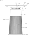
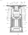
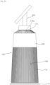
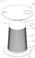
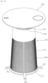
- an air cleaner comprises a first body 100 forming an inlet 116a at a peripheral surface of the first body 100 and an outlet 174a at an upper surface of the first body 100, and a second body 200 disposed above the first body 100 and guiding air discharged from the outlet 174a in a radially outward direction.
- the air cleaner may comprise a base 110 disposed under the first body 100 and contacting the ground.
- a loading part 112 (see Fig. 3 ) increasing weight may be disposed at a lower portion of the first body 100 to prevent overturn of the air cleaner.
- the loading part 112 may disposed such that a plurality of plates overlap.
- the first body 100 may comprise a lower housing 114 that disposed above the base 110 and that forms a space therein accommodating a printed circuit board that controls an electronical operation of the air cleaner.
- the lower housing 114 may be disposed above the base 110.
- the space that the printed circuit board is disposed may be formed between the lower housing 114 and the base 110.
- a filter mount plate 118 may be disposed at an upper surface of the lower housing 114.
- the filter mount plate 118 is disposed at a central portion of the lower housing 114.
- the filter mount plate 118 may disposed at the lower housing 114 to be movable in up-down direction.
- An elastic member (not shown) that maintains a position of the filter mount plate 118 may be disposed between the filter mount plate 118 and the lower housing 114. Therefore, the filter mount plate 118 may protrude upwardly by the elastic member when a filter (not shown) is not disposed on the filter mount plate 118.
- the filter mount plate 118 moves downward when the filter is mounted thereon.
- the filter mount plate 118 may sense whether the filter is mounted according to a change of disposition in up-down direction.
- the air cleaner may comprise the filter (not shown) that filters air entering the inlet 116a.
- the filter may have a cylindrical shape and be disposed inside an inlet grille 116. Therefore, it is possible to filter air flowing upward through the inlet 116a.
- the first body 100 may comprise an inner suction panel 124 spaced upward from the filter mount plate 118 or the lower housing 114 and forming an orifice 126, and may comprise a supporter 120 that connects the lower housing 114 and the inner suction panel 124.
- a plurality of supporters 120 may be disposed along a circumferential direction.
- the filter may enter through a space between the plurality of supporters 120.
- the inner suction panel 124 may form a space therebetween that the filter is disposed by being spaced upward from the filter mount plate 118 or the lower housing 114.
- the filter may be disposed between the inner suction panel 124 and the lower housing 114.
- the filter may have a cylindrical shape and filters foreign substances in air passing through a peripheral surface of the filter.
- the filter may be disposed between the inner suction panel 124 and the lower housing 114.
- the filter may downwardly pressurize the filter mount plate 118 when the filter is disposed between the inner suction panel 124 and the lower housing 114. Since the elastic member upwardly pressurize the filter, a disposition of the filter may be fixed when the filter is disposed between the inner suction panel 124 and the lower housing 114.
- the orifice 126 through which air flows to a fan 130 may be formed at a central portion of the inner suction panel 124.
- the orifice 126 may guide flowing air passing through the filter to the fan 130.
- a net steel 128 may be disposed at the orifice 126. The net steel 128 may prevent a body of the user from entering a space that the fan is disposed.
- the inlet grille 116 may be disposed at an outer periphery of the filter.
- a plurality of inlets 116a may be formed at the inlet grille 116.
- the inlet grille 116 may be disposed to cover the outer periphery of the filter, an outer periphery of the lower housing 114.
- the inlet grille 116 may be disposed to cover an outer periphery of the fan housing 140 described below.
- the inlet 116a formed at the inlet grille 116 may be formed at a peripheral surface of a region that the filter is disposed.
- the air cleaner may comprise the fan 130 rotatably disposed inside the first body 100 and may comprise a fan motor 144 rotating the fan 130.
- the first body 100 may comprise a fan housing 140 located above the filter and forming a space that the fan 130 is disposed in.
- the fan 130 that is disposed above the inner suction panel 124 and that blows upwardly air introduced through the orifice 126, and the fan motor 144 that is disposed above the fan housing 140 and driving the fan 130 may be disposed in the first body 100.
- the fan 130 may have a structure of oblique-flow fan forming a fan suction hole 130a that is opened downwardly and forming a fan discharging hole 130b that is opened upwardly radially outwardly.
- the fan 130 may comprise a hub 132 connected to the fan motor 144, a shroud 136 spaced apart from the hub 132 and forming the fan suction hole 130a, and a plurality of blades 134 spaced apart in a circumferential direction.
- the fan discharging hole 130b may be formed between the hub 132 and the shroud 136.
- the plurality of blades 134 may induce air flow discharged from the fan suction hole 130b.
- the fan housing 140 may disposed above the inner suction panel 124.
- the fan housing 140 may form a space in that the fan 130 is disposed.
- the fan housing 140 may form a space that is above the fan 130 and that the fan motor 144 is disposed.
- the fan housing 140 may form a flow path guiding air blown by the fan 130 upwardly.
- the fan housing 140 may have a cylindrical shape that is opened in up-down direction.
- a motor cover 141 may be disposed at a central portion of the fan housing 140 that the fan motor 144 is disposed.
- the motor cover 141 may have a bowl shape that is depressed downwardly such that the fan motor 144 is disposed.
- the fan housing 140 may comprise a guide vane 142 disposed above the space that the fan 130 is disposed and reducing vorticity of air discharged from the fan 130.
- the guide vane 142 may be disposed to connect an inner circumferential surface of the fan housing 140 and an outer circumferential surface of the motor cover 141.
- a plurality of guide vanes 142 may be spaced apart in a circumferential direction.
- the first body 100 may comprise a discharge guider 150 that upwardly guides air flowing upward of the fan housing 140.
- the discharge guider 150 may be disposed above the fan housing 140 and may form an annular flow path 150a therein.
- the discharge guider 150 may comprise an outer guider 152 that has a cylindrical shape and that extends along up-down direction and an inner guider 154 that is disposed radially inward of the outer guider 152 and that extends along up-down direction.
- An upward flow path 150a that has an annular shape may be formed between the outer guider 152 and the inner guider 154.
- the outer guider 152 may extend from an outer peripheral surface of the fan housing 140.
- the inner guider 154 may extend upwardly from the motor cover 141.
- connection cover 156 described below, that an insertion pole 212 (see Fig. 6 ) of the second body 200 is inserted may be disposed at an upper portion of the inner guider 154.
- the connection cover 156 may form a space for insertion of the insertion pole 212 by being depressed downwardly.
- Connection terminals 158a, 158b that are coupled to corresponding terminals 214a, 214b (see Fig. 6 ) of the insertion pole 212 may be disposed at a lower portion of the connection cover 156.
- connection terminals 158a, 158b may comprise a signal terminal that transmits signal and a power terminal that provides power.
- the connection terminals may comprise a first connection terminal 158a that provides power and a second terminal 158b that transmits signal.
- the first body 100 may comprise an upper housing 160 that forms the outlet 174a through which air flowing upward of the discharge guider 150 is discharged.
- the upper housing 160 may be disposed to cover a periphery of the discharge guider 150.
- the upper housing 160 may have a structure that extends upwardly from the inlet grille 116.
- the upper housing 160 may comprise an outer cover 162 that extends upwardly from the inlet grille and an inner cover 164 that is disposed radially inward of the outer cover 162 and that extends upward of the inlet grille 116 and an outlet grille 174 that connects the inner cover 164 and an upper end portion of the outer cover 162.
- the outer cover 162 may be disposed to cover a periphery of the discharge guider 150.
- the outer cover 162 may be disposed to extend upward of the inlet grille 116.
- the inner cover 164 may guide such that the insertion pole 212 is inserted into the connection cover 156.
- the inner cover 164 may has a structure that extends upwardly from the connection cover 156.
- the inner cover 164 may have a substantially cylindrical shape and the insertion pole 212 may be disposed inside the inner cover 164.
- a fastening rib 166a, 166b (see Fig. 4 ) that is coupled to the connection cover 156 may be disposed at an inner peripheral surface of the inner cover 164.
- two fastening ribs 166a, 166b disposed in opposite directions to each other may be disposed at the inner peripheral surface of the inner cover 164.
- Two fastening ribs 166a, 166b may be disposed to face each other, respectively, and may be of the same size.
- a fastening hole 172a, 172b that a hook 270 disposed at the second body 200 is inserted may be formed at an inner peripheral surface of the inner cover 164.
- the fastening holes 172a, 172b may be in a pair disposed in opposite directions to each other.
- Each of the pair of fastening holes 172a, 172b may be disposed above each of the two fastening ribs 166a, 166b.
- An upper groove 170a, 170b that guides the hook 270 to the fastening hole 172a, 172b may be formed at an inner peripheral surface of the inner cover 164.
- the upper groove 170a, 170b may formed above the fastening hole 172a, 172b.
- the fastening hole 172a, 172b may be spaced downward from an upper end portion of the inner cover 164.
- Two guide ribs 168a, 168b formed to mount the second body 200 to same location may be formed at an inner peripheral surface of the inner cover 164.
- Two guide ribs 168a, 168b may be disposed in opposite direction to each other. Sizes of two guide ribs 168a, 168b may be different.
- the outlet grille 174 may have a structure that extends from an upper end of the inner cover 165 toward the outer cover 162. Referring to FIG. 3 , the upper end of the inner cover 164 may be higher than an upper end of the outer cover 162.
- the upper housing 160 may comprise a plurality of outlet grille 174 that are spaced apart in a circumferential direction at an upper portion of the inner cover 164.
- Each of the plurality of outlet grille 174 may have a shape that an inclination angle at an inner end thereof and an inclination angle at an outer end thereof are different.
- the inner end of the outlet grille 174 may be a contacting portion of the outlet grille 174 and the inner cover 164.
- the outer end of the outlet grille 174 may be a contacting portion of the outlet grille 174 and the outer cover 162.
- inclination angle may mean an intersection angle of a line or plane parallel to the ground and a plane formed by the outlet grille 174.
- the outlet grille 174 may reduce vorticity of air discharged from the fan 130.
- a coupling groove 160a depressed downward and located inward of the annular outlet 174a may be formed at the first body 100.
- the coupling groove 160a may formed at an inside of the inner cover 164 that is formed at the upper housing 160.
- the coupling groove 160a may be formed inside of the inner guider 154 of the discharge guider 150.
- the connection terminal 158a, 158b that is coupled to the connection cover 156 may be disposed at the coupling groove 160a.
- the coupling groove 160a may be a region that the insertion pole 212, described below, of the second body 200 is inserted and may be formed spanned to the upper housing 160.
- a structure formed on an inner surface of the inner cover 164 and a structure formed on an inner circumferential surface of the inner guider 154 may be included at the coupling groove 160a.
- a lower surface of the second body 200 may guide air flowing upward through the outlet 174 in a radially outward direction.
- An upper surface of the second body 200 that comprises at least a flat plane, may be used as a table.
- An area formed by the upper surface of the second body 200 may be larger than an area formed by the outlet 174a.
- the outlet 174a formed at the first body 100 may have a structure hidden by the upper surface of the second body 200. Therefore, it is possible to prevent liquid or stuffs on the upper surface of the second body 200 from falling and entering into the outlet 174a.
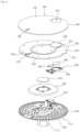
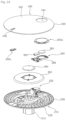
- the second body 200 may comprise a lower cover 210 that guides air discharged from the outlet 174a of the first body 100 in a radially outward direction and an upper cover 300 disposed on the lower cover 210 and a top cover 340 disposed on the upper cover 300.
- the second body 200 may further comprise a coupling portion 250 fixing the second body 200 to an upper side of the first body 100.
- the coupling portion 250 may have a structure that protrudes outward from a peripheral surface of the insertion pole 212 to fix the second body 200 when the insertion pole 212 of the second body 200 is disposed in the coupling groove 160a of the first body 100.
- the upper surface of the second body 200 may be formed of abrasion-resistant PC material. Therefore, the upper surface of the second body 200 may be formed of a material that does not abraded by stuffs thereon.
- the upper surface of the second body 200 may be formed of heat-resistant PC material. It is possible to minimize deformation thereof even if a hot object is placed on the upper surface of the second body 200.
- the lower cover 210 may be disposed to fix to the first body 100 and may guide air discharged from the outlet 174a of the first body 100 in a radially outward direction.
- the lower cover 210 may have a bowl shape that electronic units are disposed.
- the electronic unit may mean a device which is electrically operable. In the embodiment, it may mean a charging unit 380, a first lamp 362 and a second lamp 372.
- the lower cover 210 may comprise the insertion pole 212 that is inserted into the connection cover 156 of the first body 100 and a guide wall 230 that is disposed above the outlet grille 174 and that a diameter thereof expands as it goes upwardly.
- the insertion pole 212 may comprise a peripheral wall 216 that is inserted into the connection cover 156 and a lower wall 214 that is disposed at a lower end portion of the peripheral wall 216.
- the corresponding terminal 214a, 214b corresponding to the connection terminal 158a, 158b may be disposed at the lower wall 214.
- the corresponding wall 214a, 214b may comprise a terminal receiving power and a terminal receiving signal.
- Each of two corresponding terminals 214a, 214b may be connected to each of two connection terminals 158a, 158b.
- the two corresponding terminals may comprise a first corresponding terminal 214a connected to the first connection terminal 158a and a second corresponding terminal 214b connected to the second connection terminal 158b.
- the first connection terminal 158a may be connected to the first corresponding terminal 214a and the second connection terminal 158b may be connected to the second corresponding terminal 214b.
- the corresponding terminal 214a, 214b may be connected to the connection terminal 158a, 158b when the second body 200 is mounted on the first body 100.
- a fastening rib groove 218a, 218b that the fastening rib is inserted may be formed at the peripheral wall 216 when the second body 200 is mounted on the first body 100.
- Two fastening rib grooves 218a, 218b may be formed at the peripheral wall 216.
- the two fastening rib grooves 218a, 218b may be disposed in opposite directions to each other.
- a guide groove 220a, 220b that a guide rib 168a, 168b is inserted may be formed at the peripheral wall 216, when the second body 200 is mounted on the first body 100.
- Two guide grooves 220a, 220b that have a different size may be formed at the peripheral wall 216.
- Each of two guide grooves 220a, 220b may have a shape corresponding to each of two guide ribs 168a, 168b that have a different size and may be disposed a location corresponding to each of two guide ribs 168a, 168b.
- first connection terminal 158a and the second connection terminal 158b may be connected to the first corresponding terminal 214a and the second corresponding terminal 214b, respectively.
- a hook hole 222 that the hook 270, described below, of the coupling portion 250 penetrates may be formed at the peripheral wall 216.
- the hook hole 222 may be disposed above each of the coupling rib groove 218a, 218b.
- An edge groove 224 that an upper end portion of the inner cover 164 of the upper housing 160 may be formed at an upper end portion of the insertion pole 212.
- the edge groove 224 may form a groove, facing the guide wall 230, at the upper end portion of the insertion pole 212.
- the guide wall 230 may be disposed above the outlet 174a and may have a shape that extends upward of the outlet 174a.
- the guide wall 230 may have a shape that a diameter thereof expands as it goes upwardly.
- the guide wall 230 may have a shape that an inclination angle thereof increases as it goes upward from a lower end portion thereof.
- the inclination angle may mean an intersection angle between a plane parallel to the ground and the guide wall 230.
- a lower end portion of the guide wall 230 may extend from an upper end portion of the inner cover 164.
- An upper end portion of the guide wall 230 may be larger than a diameter of an peripheral surface formed by the outer cover 162.
- a hook button hole 232 that the hook button 270, described below, of the coupling portion 250 is disposed may be formed at the guide wall 230.
- a lighting hole 234 through which a part of a light source guide 364, described below, is exposed may be formed at the guide wall 230.
- the lighting hole 234 may be formed in a ring shape.
- the lighting hole 234 may be divided into a plurality of portions by a supporting rib 235 that supports the light source guide 364.
- a main button hole 236 that a button 374, described below, is disposed may be formed at the guide wall 230.
- the main button hole 236 may be formed in a number corresponding to a number of buttons 374 disposed thereon.
- the main button hole 236 may be formed in a shape corresponding to a shape button 374 disposed thereon.
- the lower cover 210 may comprise a plurality of ribs that protrudes upwardly from an upper surface of the guide wall 230.
- the lower cover 210 may comprise an edge rib 238 that protrudes upwardly from an upper end of the guide wall 230.
- the edge rib 238 may be disposed inside of a boundary wall 348 of the top cover 340.
- the edge rib 238 may be disposed outward of an outer periphery of a plate edge 304 of the upper cover 300.
- the lower cover 210 may comprise a plurality of partition ribs 240, 242 that extends upward from an upper surface thereof and that divides a space above the lower cover 210.
- the plurality of partition ribs 240, 242 may have a concentric circle structure having different radii.
- the plurality of partition ribs 240, 242 may have a structure that extend radially.
- the plurality of partition ribs 240, 242 may comprise a first partition rib 242a that is disposed to face the edge rib 238.
- the plurality of partition ribs 240, 242 may comprise a plurality of radial ribs 240 that extends from a lower end portion of an upper surface of the guide wall 230 in a radially outward direction and a plurality of circumferential ribs 242 that have different radii and that at an upper surface of the guide wall 230 and that is formed to have a ring shape.
- the plurality of circumferential ribs 242 may have the same center.
- the plurality of circumferential ribs 242 may have a same concentric center of the edge rib 238.
- the plurality of circumferential ribs 242 may have different radii and may divide a space above the lower cover 210 by protruding upwardly from the guide wall 230. Therefore, even if water from the upper cover 300, described below, enters thereinto, it is possible to prevent the water from entering inside of the lower cover 210.
- the plurality of circumferential ribs 242 may comprise a first circumferential rib 242a adjacent to the edge rib 238.
- the first circumferential rib 242a may be disposed to face the edge rib 238.
- the coupling portion 250 may couple the second body 200 to the first body 100 or decouple the second body 200 from the first body 100.
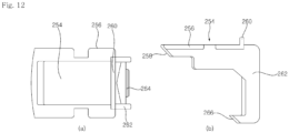
- the coupling portion 250 may comprise the hook 252 movably disposed inside the lower cover 210 and the hook button 270 that changes disposition of the hook 252.
- the coupling portion 250 may comprise a hook guider 280 disposed inside the lower cover 210 and guiding the hook 252, and an elastic member 296 disposed between the hook guider 280 and the hook 252.
- the hook 252 may comprise a first moving body 254 that contacts the hook button 270 and that moves in conjunction with a movement of the hook button 270, a second moving body 262 that is bent downward from one side of the first moving body 254, and an insertion protrusion 266 that is bent from an end portion of the second moving body 262 and is disposed to protrude outwardly.
- the first moving body 254 may form an upper wall of the moving hook 252 by contacting the hook button 270.
- the first moving body 254 may do a linear reciprocating motion in a radial direction along a space formed by the hook guider 270.
- the radial direction that the first moving body 254 moves may be set with respect to a center of circle shown when viewed from the top.
- the first moving body 254 may move in the radial direction inside the lower cover 210 by contacting with the hook button 270.
- the first moving body 254 may comprise a button contacting portion 258 that contacts with the hook button 270.
- the button contacting portion 258 may form an inclined surface to move in the radial direction when the hook button 270 moves in up-down direction.
- the first moving body 254 may extend in a direction perpendicular to a direction of movement of the first moving body 254 and may comprise a guide protrusion 256 that is disposed above an inner protrusion 288 of the hook guider 280.
- the first moving body 254 may protrude upwardly and may be disposed at a moving guide groove 290 of the hook guider 280 described below and may comprise an upper protrusion 260 that restricts a movement range of the first moving body 254.
- the lower surface of the hook button 270 may form a continuous surface to the guide wall 230. That is, it is possible to maintain streamline of air flowing along the guide wall 230.
- the hook button 270 may comprise a press plate 272 disposed to be exposed to the hook button hole 232 of the lower cover 210 and a hook contacting portion 274 disposed above the press plate 272 and contacting the button contacting portion 258.
- the hook contacting portion 274 may form an inclined surface and may be disposed to contact with the button contacting portion 258.
- the hook guider 280 may be fixed to an inside of the lower cover 210.
- the hook guider 280 may guide a radial reciprocation movement of the hook 252.
- the hook guider 280 may comprise an upper wall 282 that guides a movement of the hook 252 and an end wall 292 that extends downward from an end portion of the upper wall 282.
- a fixing protrusion 284 that protrudes in an opposite direction to the end wall 292 may be disposed at the upper wall 282. Since the fixing protrusion 284 protrudes from the upper wall 282, the fixing protrusion 284 may fix the hook guider 280.
- a coupling protrusion 286 that is spaced apart from the fixing protrusion 284 and that couples the hook guider 280 to the lower cover 210 may be disposed at the upper wall 282.
- the coupling protrusion 286 may be coupled to the lower cover 210 by a fastener (not shown).
- the moving guide groove that the upper protrusion 260 of the hook 252 is disposed and that restricts a movement range of the hook 252 may be formed at the upper wall 282.
- the inner protrusion 288 protruding downward and restricting upward movement of the hook 252 may be disposed at a lower surface of the upper wall 282.
- the inner protrusion 288 may be disposed to extend along a movement direction of the hook 252.
- the end wall 292 may be perpendicular to the upper wall 282.
- the elastic member 296 that maintains a disposition of the hook 252 may be disposed between the end wall 292 and the hook 252.
- a first elastic member fixing portion 264 that fixes one end of the elastic member 296 may be disposed at the second moving body 262.
- a second elastic member fixing portion 294 that fixes the other end of the elastic member 296 may be disposed at the end wall 292.
- the elastic member 296 may push radially outward the hook 252 when the user does not apply force to the hook button 270.
- the hook button 270 may be disposed to be exposed through the hook button hole 232 when the user does not apply force to the hook button 270.
- the insertion protrusion 266 of the hook 252 may protrude outward by passing through the hook hole 222 of the lower cover 210 when the user does not apply force to the hook button 270.
- a plurality of first lamps 362, a first board 360 that operated the plurality of first lamps 362, and the light source guide 364 that guides light emitted from the first lamp 362 to a lower side of the lower cover 210 may be disposed above the lower cover 210.
- One end portion of the light source guide 364 may be disposed below the first lamp 362.
- the other end portion of the light source guide 364 may be disposed at the lighting hole 234 formed on the guide wall 230.
- a plurality of second lamps 372 that display operation state of the air cleaner and a second board 370 that operates the plurality of second lamps 372 may be disposed above the lower cover 210.
- the second board may a substantially rectangular plate shape.
- the plurality of second lamps 372 may be disposed at an upper surface of the second board 370.
- the plurality of second lamps may be disposed at the upper surface of the second board 370 to be spaced apart in a circumferential direction.
- the button 374 that controls operation or power of the air cleaner may be disposed below the second board 370.
- the button 374 may be disposed at the main button hole 236 of the lower cover 210.
- the button 374 may comprise a plurality of button portions.
- the plurality of button portions included in the button 374 may have different sizes.
- the plurality of button portions included in the button 374 may protrude in different directions with respect to the lower cover 210.
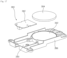
- the charging unit 380 may be disposed above the lower cover 210.
- the charging unit 380 may charge an electronic device disposed above the upper cover 300 or the top cover 340.
- the charging unit 380 may supply power, using magnetic induction or magnetic resonance method, to the electronic device disposed above the upper cover 300 or the top cover 340.
- the charging unit 380 may comprise a charging pad 384 that supplies power to electronic device adjacent thereto, a third board 382 that controls operation of the charging pad 384, an inner plate 386 that fixes the charging pad 384 and the third board 382.
- the inner plate 386 may be disposed above the light source guide 364.
- the inner plate 386 may be fixed to the light source guide 364 or the lower cover 210.
- a board fixing portion 390 (see Fig. 17 )that the third board 382 is fixed to, and a pad fixing portion 392 may be disposed at the inner plate 386.
- the pad fixing portion 392 may form a groove into which the charging pad 384 is inserted.
- the upper cover 300 may be disposed to cover an upper part of the lower cover 210.
- the upper cover may cover electronic units disposed inside the lower cover 210.
- the upper cover 300 may have a substantially disc shape.
- the upper cover 300 may have a shape corresponding to an upper surface of the lower cover 210.
- the upper cover 300 may comprise a plate 302, and at least one protruding cover 306, 308 protruding upwardly from the plate 302.
- the upper cover 300 may comprise a plurality of protruding covers 306, 308 disposed at the plate 302 and spaced apart to each other.
- the upper cover 300 may comprise the plate 302 that has a disc shape, a plate edge 304 that is bent downward from an outer periphery of the plate 302, a first protruding cover 306 that is spaced upward from the plate 302 and that covers an upper side of the charging pad 384 of the charging unit 380, a second protruding cover 308 that covers an upper side of the second lamp 372.
- a groove 322, 324 depressed downward from a periphery of the protruding cover 306, 308 may be formed at the plate 302.
- the plate 302 may have a substantially disc shape.
- the plate 302 may be disposed to cover an upper side of the lower cover 210.
- a diameter of the plate 302 may be smaller than a diameter of an upper end portion of the lower cover 210.
- the plate edge 304 may have a structure that is bent downward from an outer periphery of the plate 302.
- the diameter of the plate 302 may be larger than a diameter formed by the first circumferential rib 242a. Therefore, fluid flowing downward through the plate 302 may flow outside the first circumferential rib 242a.
- a first groove 322 depressed downward from an outer periphery of the second protruding cover 308, and a second groove 324 depressed downward from an outer periphery of the first protruding cover 306 may be formed at the plate 302.
- connection groove 326 that is disposed between the second protruding cover 308 and the first protruding cover 306 and that is depressed downward may be formed at the plate 302.
- the connection groove 326 that is connected to the plurality of grooves 322, 324 and that is depressed downward may be formed at the plate 302.
- the connection groove 326 may be formed inside the plurality of grooves 322, 324 in a ring shape.
- each of the first groove 322 and the second groove 324 may be connected to the connection groove 326.
- a depth 322h, 324h of the first groove 322 and the second groove 324 may be smaller than a depth 326h of the connection groove 326.
- widths 322w, 324w of each of the first groove 322 and the second groove 324 may be smaller than a width 326w of the connection groove 326.
- a length of the first groove 322 that extends along a periphery of the first protruding cover 306 and a length of the second groove 324 that extends along a periphery of the second protruding cover 308 may be shorter than a length of ring shape between the first groove 322 and the second groove 324 of the connection groove 326.
- the plate 302 may comprise a first plate 302a disposed radially inside of the connection groove 326, and a second plate 302b disposed radially outside of the connection groove 326.
- the first protruding cover 306 and the second protruding cover 308 may be spaced upward from the plate 302. Each of the first protruding cover 306 and the second protruding cover 308 may be disposed at a first hole 344 and a second hole 346 of the top cover 340, which is described below.
- An upper surface of the first protruding cover 306 may have a different shape from an upper surface of the second protruding cover 308.
- the upper surface of the first protruding cover 306 may have a different size from the upper surface of the second protruding cover 308.
- the top cover 340 may be disposed to cover at least portion of the upper cover 300.
- the top cover 340 may be disposed above the upper cover 300.
- a diameter of the top cover 340 may be larger than a diameter of an upper end portion of the lower cover 210. That is, an outer periphery wall of the top cover 340 may have a structure that surrounds an upper end portion of the lower cover 210. Therefore, it is possible to prevent fluid flowing outward from the top cover 340 from entering into the lower cover 210.
- the top cover 340 may be formed of abrasion-resistant PC material.
- the top cover 340 may be formed of heat-resistant PC material.
- a hole corresponding to the protruding cover 306, 308 of the upper cover 300 may be formed at the top cover 340.
- a plurality of holes 344, 346 may be formed at the top cover 340 and each of the plurality of holes 344, 346 may be located at positions corresponding to the protruding cover 306, 308.
- the top cover 340 may comprise a cover plate 342 and the boundary wall 348 that extends downwardly from an outer periphery of the cover plate 342.
- An upper surface of the cover plate 342 may be flat. Since the upper surface of the cover plate 342 is flat, the user can put stuffs on the top cover 340.
- the first hole 344 that the first protruding cover 306 is disposed and the second hole 346 that the second protruding cover 308 is disposed may be formed at the cover plate 342.
- the first hole 344 may be shaped to correspond to the first protruding cover 306.
- the second hole 346 may be shaped to correspond to the second protruding cover 308.
- the first hole 344 and the second hole 346 may have shapes different to each other.
- the first hole 344 and the second hole 346 may be disposed on a circumference that a plurality of corresponding members 352a disposed at the top cover 340 are disposed.
- the first hole 344 and the second hole 346 may be disposed on a circumference that a plurality of first magnetic members 328a disposed at the upper cover 300.
- the first hole 344 and the second hole 346 may be disposed between a plurality of magnetic members 328a, 328b.
- the top cover 340 may be disposed at same position above the upper cover 300 when the first protruding cover 306 is inserted into the first hole 344 and the second protruding cover 308 is inserted into the second hole 346.
- an upper surface of the first protruding cover 306 may form a continuous surface with the cover plate 342 of the top cover 340.
- an upper surface of the second protruding cover 308 may form a continuous surface with the cover plate 342 of the top cover 340.
- the upper surface of the first protruding cover 306 and the upper surface of the second protruding cover 308 may form flat surface together.
- the cover plate 342 In a state that the top cover 340 is mounted on the upper cover 300, the cover plate 342, the first protruding cover 306, and the second protruding cover 308 may form flat surface as a whole.
- the state that the top cover 340 is mounted on the upper cover 300 may mean the first protruding cover 306 and the second protruding cover 308 are respectively inserted into the first hole 344 and the second hole 346.
- the state that the top cover 340 is mounted on the upper cover 300 may be a state that the corresponding member 352a, 352b of the top cover 340, described below, interact with the magnetic member 328a, 328b of the upper cover 300.
- the state that the top cover 340 is mounted on the upper cover 300 may mean a state that the top cover 340 and the upper cover 300 contact by the corresponding member 352a, 352b and the magnetic member 328a, 328b.
- a plurality of ribs 350 that maintains a shape of the top cover 340 may be disposed at the top cover 340.
- the plurality of ribs 350 may protrude downward from a lower surface of the top cover 340.
- the plurality of ribs 350 may have shapes of circle concentric with respect to a center of the top cover 340.
- the plurality of ribs 350 may be radially formed with respect to the center of the top cover.
- the plurality of ribs 350 may be disposed between the plurality of corresponding members 352a, 352b.
- the plurality of magnetic members 328a, 328b may be disposed at one of the top cover 340 or the upper cover 300.
- the plurality of corresponding members 352a, 352b may be disposed at the other of the top cover 340 or the upper cover 300.
- the plurality of corresponding members 352a, 352b may be disposed at the top cover 340.
- the plurality of corresponding members 352a, 352b may comprise a plurality of first corresponding members 352a that are spaced apart from a center of the top cover 340 in a radial direction, and a plurality of second corresponding members 352b that are spaced further apart from a center of the top cover 340 in a radial direction than the first corresponding member 352a.
- the plurality of first corresponding members 352a may be disposed to be spaced apart from each other in a circumferential direction.
- the plurality of second corresponding members 352b may be disposed to be spaced apart from each other in a circumferential direction.
- the first magnetic member 328a disposed at a position corresponding to the first corresponding member 352a and the second magnetic member 328b disposed at a position corresponding to the second corresponding member 352b may be disposed at the upper cover 300.
- the plurality of magnetic members 328a, 328b may be disposed at the upper cover 300.
- the plurality of magnetic members 328a, 328b may be mounted on a lower surface of the upper cover 300.
- a magnetic member hook 329 for fixing the plurality of magnetic members 328a, 328b may be disposed at the upper cover 300.
- the plurality of magnetic members 328a, 328b may comprise a plurality of first magnetic members 328a spaced apart in a circumferential direction, and a plurality of second magnetic members 328b that is disposed on a circle concentric with a circle on which the plurality of first magnetic members 328a are arranged and spaced apart in a circumferential direction.
- a gap 328al between the plurality of first magnetic members 328a in the circumferential direction or a gap 328b1 between the plurality of second magnetic members 328b in the circumferential direction may be formed to be longer than a radius gap L1 between a radius of concentric circle formed by the plurality of first magnetic member 328a and a radius of concentric circle formed by the plurality of second magnetic member 328b.
- FIGs. 20 to 23 a second body according to a second embodiment of the present invention is described.
- a second body 200 according to the second embodiment may have same elements with the second body 200 according to the first embodiment.
- the second body 200 may comprise a lower cover 210, an upper cover 300, and a cop cover 340.
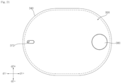
- the second body 200 may have an oval shape when viewed from the top.
- the second body 200 may have an oval shape elongated in a direction that the charging unit 380 and the second lamp 372 are disposed.
- a maximum radius thereof may be formed in a first direction d1+/d1- that the charging unit 380 and the second lamp 372 are disposed, and a minimum radius thereof may be formed in a second direction d2+/d2- that is perpendicular to the first direction d1+/d1-.
- the upper cover 300 may have an oval shape that covers an upper side of the lower cover 210.
- the upper cover 300 may comprise a plate (now shown), and at least one protruding cover 306, 308 protruding upwardly from the plate.
- the cop cover 340 may be disposed above the upper cover 300 and may have an oval shape.
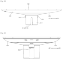
- the lower cover 210 may comprise a guide wall 230 that guides air discharged from an outlet 174a in a radially outward direction and an insertion pole 212 extending downwardly from a lower end portion of the guide wall 230 and inserted into the coupling groove 160a of the first body 100.
- the insertion pole 212 may have a structure same with the first embodiment. That is, a hole that the hook 252 protrudes may be formed at a peripheral surface of the insertion pole 212.
- a corresponding terminal 214a, 214b that is electrically connected to the connection terminal 158a, 158b (refer to FIG. 4 ) disposed at the first body 100 may be disposed at a lower wall 214 of the insertion pole 212. Therefore, regardless of a structure of the guide wall 230, the second body 200 of the second embodiment may be mounted on the coupling groove 160a (refer to FIG. 4 ) of the first body 100.
- a portion of the guide wall 230 that extends along the second direction d2/d2- may be formed to be gentler than a portion of the guide wall 230 that extends along the first direction d1+/d1-.
- FIGS. 24 , 25 a second body 200 according to a third embodiment is described.
- the second body 200 of the third embodiment may comprise a hole cover 390a, 390b and excluding the upper cover from a structure of the second body 200 according to the first embodiment.
- the structure of the second body according to the third embodiment may be applied to a structure thereof according to the second embodiment.
- the second body 200 may comprise a lower cover 210, a coupling portion 250, a second lamp 372, a charging unit 380, and a top cover 340.
- the second body may be fixed to the lower cover 210 or the top cover 340 and may comprise a hole cover 390a, 390b mounted on a hole 344, 346 formed at the top cover 340.
- the first hole 344 and the second hole 346 may be formed at the top cover 340.
- the hole cover 390a, 390b may comprise a first hole cover 390a that is disposed at the first hole 344 and a second hole cover 390b that is disposed at the second hole 346.
- the first hole cover 390a may cover an upper side of the charging unit 380 that is disposed at the lower cover 210.
- the second hole cover 390b may cover an upper side of the second lamp 372 that is disposed at the lower cover 210.
- Each of the first hole cover 390a and the second hole cover 390b may be sized to correspond to the first hole 344 and the second hole 346.
- Each of the first hole cover 390a and the second hole cover 390b may comprise an upper hole covers 392 that are respectively disposed at the first hole 344 and the second hole 346, and a lower hole cover 394 that is disposed below the top cover 340, and a connection plate 396 that extends from the lower hole cover 394 in a radially outward direction.
- Each of the first hole cover 390a and the second hole cover 390b may comprise an upper hole cover 392 that is disposed at the first hole 344, and a lower hole cover 394 that is disposed at an outer periphery of the upper hole cover 392 and that forms a groove depressed downward, and a connection plate 396 that extends from an outer periphery of the lower hole cover 394 in a radial direction.
- the upper hole cover 392 may have a cylindrical shape that an upper side thereof is closed and that is flat.
- the upper hole cover 392 may comprise an upper peripheral wall 392b that extends downward along an edge of an upper plate 392a.
- An upper surface of the upper hole cover 392 may form a continuous surface with an upper surface formed by the top cover 340.
- the lower hole cover 394 may be disposed at a lower end portion of the upper hole cover 392.
- the lower hole cover 394 may have a structure that extends from a lower end portion of the upper peripheral wall 392b in a radially outward direction. Therefore, the lower hole cover 394 may have a ring shape that extends along the outer periphery of the upper hole cover 392.
- the lower hole cover 394 may have a shape of groove that is depressed downward. Therefore, even if water spilled from an upper side of the top cover 340 moves downward through the first hole 344, it is possible to prevent the filled water entering into the lower over 210.
- connection plate 396 may have a structure that extends from the lower periphery of the lower hole cover 394 in a radially outward direction.
- connection plate 396 may be fixed to the lower cover 210 or the top cover 340.
- connection plate 396 may be fixed to the lower cover 210 and may be that a magnetic member is disposed thereat.
- a corresponding member (not shown) may be disposed at a position corresponding to the magnetic member 328 at the top cover 340. Therefore, the top cover 340 may contact the lower cover 210 or the hole cover 390a, 390b when the top cover 340 is disposed above the lower cover 210.
- FIGS. 26 , 27 a second body 200 according to a fourth embodiment is described.
- the second body 200 according to the fourth embodiment may differ from the second body 200 according to the first embodiment in that the top cover 340 is coupled to one side of the lower cover 210.
- the magnetic member and the corresponding member are deleted from the second body 200 according to the first embodiment and the top cover 340 is fixed to the lower cover 210 by another fastening structure.
- the second body 200 may comprise a lower cover 210, an upper cover 300, and a top cover 340.
- Other element of the second body may be same with the elements of the first embodiment.
- a top cover protrusion 348a fixed to the lower cover 210 may be disposed at the top cover 340.
- the top cover protrusion 348a may be disposed at a lower end portion of a boundary wall 348 of the top cover 340.
- the top cover 340 may comprise a disc-shaped cover plate 342 and a boundary wall 348 that extends downwardly from an outer circumferential end of the cover plate 342 and may be that the top cover protrusion 348a protruding radially inward is disposed at a lower end portion of the boundary wall 348.
- the top cover protrusion 348a may be formed at a whole surface of the boundary wall 348 or at a plurality of areas spaced apart in a circumferential direction.
- a rib groove 238a that the top cover protrusion 348a is inserted may be formed at the lower cover 210.
- the lower cover 210 may comprise a guide wall 230 extending in a radially outward direction above the outlet 174a and an edge rib 238 extending upwardly from an outer circumferential end portion of the guide wall 230 and may be that the rib groove 238a is formed at a lower end portion of the edge rib 238.
- the rib groove 238a may be formed above the guide wall 230.
- an outer circumferential end of the guide wall 230 may have a structure that protrudes further than a lower end of the edge rib 238 in a radially outward direction. Air discharged from the outlet 174a may flow from an inner circumferential end and an outer circumferential end of the guide wall 230 in a radially outward direction.
- the lower end portion of the boundary wall 348 of the top cover 340 may be disposed to contact an upper surface of the guide wall 230 in a state that the top cover 340 is mounted on the lower cover 210.
- FIGS. 28 and 29 disclose that a second body 200 that is mounted on an upper side of the first body 100 and that performs other function.
- the second body 200 may perform a function of outputting an image, or video.
- the second body 200 may comprise a structure of the insertion pole 212 and a display 400a may be disposed above the insertion pole 212.
- the insertion pole 212 may have a structure that is fixed to the coupling groove 160a.
- the corresponding terminal 214a, 214b may be connected to the connection terminal 158a, 158b disposed at the coupling groove 160a when the insertion pole 212 is mounted on the coupling groove 160a of the first body 100.
- the second body 200 may perform as a light that emits light.
- the second body 200 may have a structure of the insertion pole 212, that is mounted on the first body 100, at a lower portion thereof and a light 400b may be disposed above the insertion pole 212.
- the first body 100 may further comprise the base supporter 102 that is fixed to one side of the first body 100 and that supports the air cleaner against the ground.
- the base supported according to the first embodiment may be opened in up-down direction and may have a cone shape that an upper end thereof is cut.
- the base supporter 102 may have a shape that a radius thereof expands as it goes upward.
- the base supporter 102 may be disposed under the inlet grille 116.
- the base supporter 102 may be disposed at an outer periphery of the base 110.
- the base supporter 102 may have a structure that is mounted on an upper side of the base 110.
- a diameter of an upper end portion 102a of the base supporter 102 may be smaller than a diameter of a lower end portion 116a of the inlet grille 116. Therefore, an upper end of the base supporter 102 may be fixed thereto. A lower end 102b of the base supporter 102 may be disposed to contact the ground. The diameter of the upper end portion 102a of the base supporter 102 may be larger than a diameter of a lower end portion 160a of the upper housing 160.
- the base supporter 102 may be inserted into an upper side of the base 110 in a state that the second body 200 and the inlet grille 116 are separated.
- the base supporter 102 may have a bar-shaped structure separately mounted on the base 110.
- a supporter groove 111 that the base supporter 102 is mounted may be formed at the base 110.
- the supporter groove 111 that one end portion of the base supporter 102 is mounted may be formed at the base 110.
- the base supporter 102 may comprise an insertion portion 104 that is inserted into the supporter groove 111 and an extension portion 106 extending in a radially outward direction from an upper end of the insertion portion 104.
- An engagement protrusion 104a that fixes the base supporter 102 to the supporter groove 111 may be formed at a lower end of the insertion portion 104.
- the engagement protrusion 104a may have a structure that protrudes in a radially outward direction from the lower end of the insertion portion 104.
- the extension portion 106 may have a structure that is bent from an upper end of the insertion portion 104 and extends in a radially outward direction.
- the extension portion 106 may have a structure that extends downward as it goes away from the insertion portion 104. Therefore, an outer end of the extension portion 106 may have a structure that contacts the ground.
Landscapes
- Engineering & Computer Science (AREA)
- Chemical & Material Sciences (AREA)
- Combustion & Propulsion (AREA)
- Mechanical Engineering (AREA)
- General Engineering & Computer Science (AREA)
- Human Computer Interaction (AREA)
- Computer Networks & Wireless Communication (AREA)
- Power Engineering (AREA)
- Filtering Of Dispersed Particles In Gases (AREA)
- Chemical Kinetics & Catalysis (AREA)
- Air Filters, Heat-Exchange Apparatuses, And Housings Of Air-Conditioning Units (AREA)
- Cooling Or The Like Of Electrical Apparatus (AREA)
Abstract
Description
- The present invention is related to an air cleaner, more specifically, to the air cleaner capable of utilizing a space above the air cleaner.
- The air cleaner is a device that forms an air flow and that increases an air clearness of air in a certain space after filtering the flowing air.
- The air cleaner may have an element that the filter is disposed and that an inlet is formed at one side thereof and that an outlet formed at the other side thereof.
- The air cleaner may form the outlet at an upper side thereof and may discharge the filtered air all around to quickly increase the air clearness of an indoor space.
-
KR 10-2021-0137720 - The objective of the present invention is to provide the filtered air quickly and widely to the indoor space and to provide an air cleaner capable of utilizing a space above the air cleaner.
- Another objective of the present invention is to provide an air cleaner that can utilize a space above the air cleaner as the table.
- Another objective of the present invention is to provide an air cleaner that can be separated and coupled in various ways, so that the user can use tables of various sizes according to the user's preferences.
- Another objective of the present invention is to provide an air cleaner with a structure that prevents foreign substances falling from the table from interfering with operation of the air cleaner.
- Another objective of the present invention is to provide an air cleaner that minimizes shape deformation caused by friction with objects placed on an upper side of the air cleaner.
- Another objective of the present invention is to provide an air cleaner that increases flow rate of the filtered air.
- Another objective of the present invention is to provide an air cleaner that prevents fluid flowing down from the top surface of the air cleaner, which is used as a table, from entering an inside where electronic units are placed.
- Another objective of the present invention is to provide an air cleaner that can facilitate to mount of an upper structure of the air cleaner easily and on the fixed position.
- Another objective of the present invention is to provide an air cleaner that reliably send electrical signal or power to the upper structure mounted on an upper side of the air cleaner.
- Another objective of the present invention is to provide an air cleaner that prevent the air cleaner being flipped.
- The objectives of the present invention are achieved with an air cleaner according to
claim 1. - To solve the objectives above, an air cleaner according to an embodiment of the present invention may comprise a first body comprising an inlet formed at a peripheral surface thereof, and an outlet disposed above the inlet; a fan rotatably disposed between the inlet and the outlet to induce air flow from the inlet to the outlet; a filter removing foreign substance in air introduced through the inlet; and a second body disposed above the first body and guiding air discharged from the outlet in a radially outward direction, wherein a lower surface of the second body is disposed above the outlet and extends in the radially outward direction as it goes upward, and wherein an upper surface of the second body forms a flat surface in at least a part area. Therefore, it is possible to perform air cleaning by lower configurations and to use upper configurations as the table.
- An area formed by the upper surface of the second body may be larger than an area formed by the outlet so that objects placed on an upper side of the table do not fall toward the outlet.
- The second body may comprise a lower cover fixed to the first body and extending in the radially outward direction as it goes upward to guide air discharged from the outlet; and a top cover separably disposed on an upper side of the lower cover and forming the flat surface.
- The top cover may be formed of an abrasion-resistant PC material so that the shape deformation caused by impact generated at an upper side of the top cover is minimized.
- The lower cover may form a curved surface that an inclination angle of tangential line is getting larger as it goes upward.
- The lower cover may be bowl-shaped to form a space that electronic units are disposed, and wherein the second body further comprises an upper cover disposed between the lower cover and the top cover to cover at least portion of an upper side of the lower cover so that upper side of the electronic units disposed inside the lower cover can be covered twice.
- The upper cover may comprise a plate, and at least one protruding cover protruding upward from the plate, and wherein a hole corresponding to the protruding cover is formed at the top cover, so that it is possible to check mounting position when the top cover is mounted on an upper side of the upper cover.
- A plurality of protruding covers having different shapes and spaced apart in a circumferential direction may be disposed at the upper cover, and wherein a plurality of holes corresponding to each of the plurality of protruding covers are formed at the top cover, so that it is possible to check mounting position when the top cover is mounted on an upper side of the upper cover.
- The second body may further comprise a lamp disposed in the lower cover and displaying an operation state of the fan, and a charging unit supplying power to an electronic product disposed above the top cover by wireless charging and disposed in the lower cover, wherein a first protruding cover protruding upward to cover an upper side of the charging unit, and a second protruding cover protruding upward to cover an upper side of the lamp are disposed at the upper cover, and wherein a first hole corresponding to the first protruding cover, and a second hole corresponding to the second protruding cover are formed at the top cover, so that it is possible to check mounting position when the top cover is mounted on an upper side of the upper cover.
- The lower cover may comprise a guide wall disposed above the outlet to guide air discharged from the outlet, and an insertion pole extending downward from a lower end portion of the guide wall, wherein the outlet is annular-shaped, and wherein a coupling groove is formed at the first body such that the insertion pole is inserted into the coupling groove at a center which inside of the annular outlet, so that the second body can be separated from the first body or can be coupled to the first body.
- A first connection terminal supplying power to the second body and a second connection terminal transmitting signal to the second body may be disposed at a lower end portion of the coupling groove, and wherein a first corresponding terminal connected to the first connection terminal and a second corresponding terminal connected to the second connection terminal are disposed at a lower surface of the insertion pole, so that the first body and the second body can be electrically connected when the second body is mounted on the first body.
- A plurality of guide ribs that have different shapes may be disposed at one of the coupling groove of the first body or a peripheral wall of the insertion pole, and wherein a plurality of guide grooves that the plurality of guide ribs are respectively inserted are disposed at the other of the coupling groove of the first body or a peripheral wall of the insertion pole, so that mounting the second body can be mounted on the first body at the same position.
- The air cleaner may further comprise a base disposed below the first body and disposed to contact the ground, and wherein the base is shaped to expand in a radial direction as it goes downward from the first body, so that it is possible to maintain the position of the first body without being flipped.
- A diameter of a lower end portion of the base may be larger than a diameter of the first body, so that it is possible to maintain the position of the first body without being flipped.
- The air cleaner may further comprise a base disposed below the first body and disposed to contact the ground; and a base supporter comprising a first end portion fixed to the base and a second end portion disposed to contact the ground, so that it is possible to maintain the position of the first body without being flipped.
- An air cleaner according to an embodiment of the present invention may comprise a first body comprising an inlet formed at a peripheral surface thereof, and an outlet disposed above the inlet; a fan rotatably disposed between the inlet and the outlet to induce air flow from the inlet to the outlet; a filter removing foreign substance in air introduced through the inlet; and a second body disposed above the first body and guiding air discharged from the outlet in a radially outward direction, wherein the second body comprises a lower cover comprising a guide wall that extends in the radially outward direction to guide air discharged from the outlet, and an insertion pole extending downward from a lower end portion of the guide wall; and a top cover disposed above the lower cover and forming a flat surface, wherein the outlet is annular-shaped, and wherein a coupling groove that the insertion pole is inserted is formed at the first body, the coupling groove radially inside of the annular outlet, so that the second body with a variety of sizes can be placed or replaced on the first body.
- A first connection terminal supplying power to the second body and a second connection terminal transmitting signal to the second body may be disposed at the coupling groove, so that the second body can be electrically connected to the first body when the second body is mounted on the first body.
- A plurality of guide ribs that have different shapes may be disposed at one of the coupling groove of the first body or a peripheral wall of the insertion pole.
- The second body may comprise a coupling portion protruding toward an inner peripheral surface of the coupling groove to fix the second body when the second body is inserted into the coupling groove.
- An air cleaner according to an embodiment of the present invention may comprise a first body comprising an inlet formed at a peripheral surface thereof, an annular outlet disposed above the inlet, and a coupling groove disposed inside of the annular outlet and depressed downward; a fan rotatably disposed between the inlet and the outlet to induce air flow from the inlet to the outlet; a filter removing foreign substance in air introduced through the inlet; and a second body mounted on the coupling groove of the first body and electrically connected to the first body when the second body is mounted on the coupling groove, so that electricity can be supplied to the second body which is mounted on the first body.
- The second body may comprise a coupling portion protruding toward an inner peripheral surface of the coupling groove to fix the second body when the second body is inserted into the coupling groove, so that the second body can which is mounted on the first body can be stably fixed thereto.
- Details of the embodiments and the like are included in the detailed description and drawings.
- According to an air cleaner of the present invention, following effects one or more.
- First, it is possible to quickly diffuse the filtered air to the indoor space by disposing a second body above the air cleaner that discharges the filtered air upward and by guiding air discharged from the outlet in a radial direction. In addition, since the first body has a structure that the second body is coupled to an inside of the outlet, it is possible to utilize the space above the air cleaner.
- Second, by placing the second body that guides air upwardly and functions as a table, it is possible to utilize the second body as a table. The advantage of this is to increase the space utilization by combining an air purifier with a table into a single device that is used in a space where the user may place objects or take a rest.
- Third, since the second body is mounted on the first body, it is possible to change the table, mounted on the first body, with variety of structures or sizes. The advantage of this is to increase the space utilization by changing the size or shape of the table according to the user's preferences.
- Fourth, since a size of an upper surface of the second body is larger than a size of the outlet, it is possible to prevent object or fluid on an upper side of the structure used as the table from falling to the outlet. The advantage of this is to prevent a breakdown of the air cleaner or safety accident.
- Fifth, an upper surface of the second body and/or the top cover is made of material that is resistant to heat and abrasion, thereby minimizing deformation or abrasion of an upper surface of the second body caused by objects placed on the upper surface of the second body.
- Sixth, since flowing direction of air which is discharged in a radial direction by an inclined shape of the lower surface of the second body prevents vortices, it is possible to increase flow rate of the filtered air and to quickly increase air quality of indoor space.
- Seventh, since a state that the second body is mounted on an upper side of the first body is maintained, it is possible to stably separate the second body from the first body.
- Eighth, when the second body is mounted on the first body, the first, second body are electrically connected. In addition, since terminals for connecting power and signal are connected at exact positions when the second body is mounted on the first body, there is advantage of stably performing electrical operations.
- Ninth, there is a risk that the entire structure may be overturned by external pressure because an upper side of the air cleaner is relatively large. However, the air cleaner can be stably placed by the shape of a base disposed below the first body and by the structure of a base supporter placed around the base.
- The effects of the present invention are not limited to the effects mentioned above, and other effects not mentioned would be clearly understood from the claims by those who skilled in the art.
-
-
FIG. 1 shows a perspective view of an air cleaner according to the first embodiment of the present invention. -
FIG. 2 shows a side view ofFIG. 1 . -
FIG. 3 shows a sectional view of the air cleaner according to the first embodiment of the present invention. -
FIG. 4 shows a plan view of the lower body according to the first embodiment of the present invention. -
FIG. 5 shows a plan view of the upper body according to the first embodiment of the present invention. -
FIG. 6 shows a sectional view cut along line X-X' inFIG. 5 . -
FIG. 7 shows a sectional view cut along line Y-Y' inFIG. 5 . -
FIG. 8 shows an exploded perspective view of the upper body according to the first embodiment of the present invention. -
FIG. 9 shows a bottom view of the lower cover according to the first embodiment of the present invention. -
FIG. 10 shows a plan view of the lower cover according to the first embodiment of the present invention. -
FIG. 11 shows an exploded perspective view of the coupling part according to the first embodiment of the present invention. -
FIG. 12 shows the hook according to a first embodiment of the present invention, wherein (a) shows a plan view and (b) shows a side view. -
FIG. 13 shows the hook guider according to the first embodiment of the present invention, wherein (a) shows a bottom view and (b) shows a front view. -
FIG. 14 shows the hook button according to the first embodiment of the present invention, wherein (a) shows a plan view and (b) shows a side view. -
FIG. 15 shows a perspective view of the upper cover according to the first embodiment of the present invention. -
FIG. 16 shows a plan view ofFIG. 15 . -
FIG. 17 shows an exploded perspective view of the charging unit according to the first embodiment of the present invention. -
FIG. 18 shows a bottom view of the top cover according to the first embodiment of the present invention. -
FIG. 19 shows a sectional view that the disposition of the coupling part is changed from the second body shown inFIG. 6 . -
FIG. 20 shows a perspective view of the second body according to the second embodiment of the present invention. -
FIG. 21 shows a plan view ofFIG. 20 . -
FIG. 22 shows a side view in one direction ofFIG. 20 . -
FIG. 23 shows a side view in another direction ofFIG. 20 . -
FIG. 24 shows an exploded perspective view of the second body according to the third embodiment of the present invention. -
FIG. 25 is for explaining the structure of the hole cover included in the second body of the third embodiment of the present invention, wherein (a) shows a plan view of the first hole cover and (b) shows a plan view of the second hole cover. -
FIG. 26 shows an exploded perspective view of the second body according to the fourth embodiment of the present invention. -
FIG. 27 shows a sectional view for explaining the coupling relationship of the second body of the fourth embodiment of the present invention. -
FIG. 28 shows the air cleaner equipped with the second body according to the fifth embodiment of the present invention. -
FIG. 29 shows the air cleaner equipped with the second body according to the sixth embodiment of the present invention. -
FIG. 30 shows a perspective view of the air cleaner at which the base supporter according to the first embodiment is added to the air cleaner according to the first embodiment. -
FIG. 31 shows a side view ofFIG. 30 . -
FIG. 32 shows a perspective view of the air cleaner at which the base supporter according to the second embodiment is added to the air cleaner according to the first embodiment. -
Fig. 33 is a sectional view ofFIG. 32 . - Advantages and features of the present invention, and methods of achieving them will become clear with reference to the detailed description of the following embodiments taken in conjunction with the accompanying drawings. However, the present invention is not limited to the embodiments disclosed below and can be implemented in various forms, these embodiments are provided only to make the disclosure of the present invention complete, and to fully inform those skilled in the art of the scope of the invention to which the present invention belongs, the present invention is only defined by the scope of the claims.
- Hereinafter, referring to figures, an air cleaner according to embodiments of the present invention will be described.
- Referring to
FIGs. 1 to 3 , an air cleaner comprises afirst body 100 forming aninlet 116a at a peripheral surface of thefirst body 100 and anoutlet 174a at an upper surface of thefirst body 100, and asecond body 200 disposed above thefirst body 100 and guiding air discharged from theoutlet 174a in a radially outward direction. - Referring to
FIG. 3 , the air cleaner may comprise a base 110 disposed under thefirst body 100 and contacting the ground. A loading part 112 (seeFig. 3 ) increasing weight may be disposed at a lower portion of thefirst body 100 to prevent overturn of the air cleaner. Theloading part 112 may disposed such that a plurality of plates overlap. - The
first body 100 may comprise alower housing 114 that disposed above thebase 110 and that forms a space therein accommodating a printed circuit board that controls an electronical operation of the air cleaner. Thelower housing 114 may be disposed above thebase 110. The space that the printed circuit board is disposed may be formed between thelower housing 114 and thebase 110. - A
filter mount plate 118 may be disposed at an upper surface of thelower housing 114. Thefilter mount plate 118 is disposed at a central portion of thelower housing 114. Thefilter mount plate 118 may disposed at thelower housing 114 to be movable in up-down direction. An elastic member (not shown) that maintains a position of thefilter mount plate 118 may be disposed between thefilter mount plate 118 and thelower housing 114. Therefore, thefilter mount plate 118 may protrude upwardly by the elastic member when a filter (not shown) is not disposed on thefilter mount plate 118. - The
filter mount plate 118 moves downward when the filter is mounted thereon. Thefilter mount plate 118 may sense whether the filter is mounted according to a change of disposition in up-down direction. - The air cleaner may comprise the filter (not shown) that filters air entering the
inlet 116a. The filter may have a cylindrical shape and be disposed inside aninlet grille 116. Therefore, it is possible to filter air flowing upward through theinlet 116a. - The
first body 100 may comprise aninner suction panel 124 spaced upward from thefilter mount plate 118 or thelower housing 114 and forming anorifice 126, and may comprise asupporter 120 that connects thelower housing 114 and theinner suction panel 124. - A plurality of
supporters 120 may be disposed along a circumferential direction. The filter may enter through a space between the plurality ofsupporters 120. - The
inner suction panel 124 may form a space therebetween that the filter is disposed by being spaced upward from thefilter mount plate 118 or thelower housing 114. The filter may be disposed between theinner suction panel 124 and thelower housing 114. The filter may have a cylindrical shape and filters foreign substances in air passing through a peripheral surface of the filter. The filter may be disposed between theinner suction panel 124 and thelower housing 114. - The filter may downwardly pressurize the
filter mount plate 118 when the filter is disposed between theinner suction panel 124 and thelower housing 114. Since the elastic member upwardly pressurize the filter, a disposition of the filter may be fixed when the filter is disposed between theinner suction panel 124 and thelower housing 114. - The
orifice 126 through which air flows to afan 130, which is described below, may be formed at a central portion of theinner suction panel 124. Theorifice 126 may guide flowing air passing through the filter to thefan 130. Anet steel 128 may be disposed at theorifice 126. Thenet steel 128 may prevent a body of the user from entering a space that the fan is disposed. - The
inlet grille 116 may be disposed at an outer periphery of the filter. A plurality ofinlets 116a may be formed at theinlet grille 116. Theinlet grille 116 may be disposed to cover the outer periphery of the filter, an outer periphery of thelower housing 114. Theinlet grille 116 may be disposed to cover an outer periphery of thefan housing 140 described below. Theinlet 116a formed at theinlet grille 116 may be formed at a peripheral surface of a region that the filter is disposed. - The air cleaner may comprise the
fan 130 rotatably disposed inside thefirst body 100 and may comprise afan motor 144 rotating thefan 130. - The
first body 100 may comprise afan housing 140 located above the filter and forming a space that thefan 130 is disposed in. - The
fan 130 that is disposed above theinner suction panel 124 and that blows upwardly air introduced through theorifice 126, and thefan motor 144 that is disposed above thefan housing 140 and driving thefan 130 may be disposed in thefirst body 100. - The
fan 130 may have a structure of oblique-flow fan forming afan suction hole 130a that is opened downwardly and forming afan discharging hole 130b that is opened upwardly radially outwardly. Thefan 130 may comprise ahub 132 connected to thefan motor 144, ashroud 136 spaced apart from thehub 132 and forming thefan suction hole 130a, and a plurality ofblades 134 spaced apart in a circumferential direction. Thefan discharging hole 130b may be formed between thehub 132 and theshroud 136. The plurality ofblades 134 may induce air flow discharged from thefan suction hole 130b. - The
fan housing 140 may disposed above theinner suction panel 124. Thefan housing 140 may form a space in that thefan 130 is disposed. Thefan housing 140 may form a space that is above thefan 130 and that thefan motor 144 is disposed. Thefan housing 140 may form a flow path guiding air blown by thefan 130 upwardly. - The
fan housing 140 may have a cylindrical shape that is opened in up-down direction. Amotor cover 141 may be disposed at a central portion of thefan housing 140 that thefan motor 144 is disposed. Themotor cover 141 may have a bowl shape that is depressed downwardly such that thefan motor 144 is disposed. - The
fan housing 140 may comprise aguide vane 142 disposed above the space that thefan 130 is disposed and reducing vorticity of air discharged from thefan 130. Theguide vane 142 may be disposed to connect an inner circumferential surface of thefan housing 140 and an outer circumferential surface of themotor cover 141. A plurality ofguide vanes 142 may be spaced apart in a circumferential direction. - The
first body 100 may comprise adischarge guider 150 that upwardly guides air flowing upward of thefan housing 140. Thedischarge guider 150 may be disposed above thefan housing 140 and may form anannular flow path 150a therein. - The
discharge guider 150 may comprise anouter guider 152 that has a cylindrical shape and that extends along up-down direction and aninner guider 154 that is disposed radially inward of theouter guider 152 and that extends along up-down direction. - An
upward flow path 150a that has an annular shape may be formed between theouter guider 152 and theinner guider 154. Theouter guider 152 may extend from an outer peripheral surface of thefan housing 140. Theinner guider 154 may extend upwardly from themotor cover 141. - A
connection cover 156, described below, that an insertion pole 212 (seeFig. 6 ) of thesecond body 200 is inserted may be disposed at an upper portion of theinner guider 154. Theconnection cover 156 may form a space for insertion of theinsertion pole 212 by being depressed downwardly.Connection terminals corresponding terminals Fig. 6 ) of theinsertion pole 212 may be disposed at a lower portion of theconnection cover 156. - The
connection terminals first connection terminal 158a that provides power and asecond terminal 158b that transmits signal. - The
first body 100 may comprise anupper housing 160 that forms theoutlet 174a through which air flowing upward of thedischarge guider 150 is discharged. - The
upper housing 160 may be disposed to cover a periphery of thedischarge guider 150. Theupper housing 160 may have a structure that extends upwardly from theinlet grille 116. - The
upper housing 160 may comprise anouter cover 162 that extends upwardly from the inlet grille and aninner cover 164 that is disposed radially inward of theouter cover 162 and that extends upward of theinlet grille 116 and anoutlet grille 174 that connects theinner cover 164 and an upper end portion of theouter cover 162. - The
outer cover 162 may be disposed to cover a periphery of thedischarge guider 150. Theouter cover 162 may be disposed to extend upward of theinlet grille 116. - The
inner cover 164 may guide such that theinsertion pole 212 is inserted into theconnection cover 156. Theinner cover 164 may has a structure that extends upwardly from theconnection cover 156. Theinner cover 164 may have a substantially cylindrical shape and theinsertion pole 212 may be disposed inside theinner cover 164. - A
fastening rib 166a, 166b (seeFig. 4 ) that is coupled to theconnection cover 156 may be disposed at an inner peripheral surface of theinner cover 164. Referring toFIG. 13 , twofastening ribs 166a, 166b disposed in opposite directions to each other may be disposed at the inner peripheral surface of theinner cover 164. Twofastening ribs 166a, 166b may be disposed to face each other, respectively, and may be of the same size. - A
fastening hole hook 270 disposed at thesecond body 200 is inserted may be formed at an inner peripheral surface of theinner cover 164. The fastening holes 172a, 172b may be in a pair disposed in opposite directions to each other. Each of the pair offastening holes fastening ribs 166a, 166b. - An
upper groove hook 270 to thefastening hole inner cover 164. Theupper groove fastening hole fastening hole inner cover 164. - Two
guide ribs second body 200 to same location may be formed at an inner peripheral surface of theinner cover 164. Twoguide ribs guide ribs - The
outlet grille 174 may have a structure that extends from an upper end of the inner cover 165 toward theouter cover 162. Referring toFIG. 3 , the upper end of theinner cover 164 may be higher than an upper end of theouter cover 162. Theupper housing 160 may comprise a plurality ofoutlet grille 174 that are spaced apart in a circumferential direction at an upper portion of theinner cover 164. - Each of the plurality of
outlet grille 174 may have a shape that an inclination angle at an inner end thereof and an inclination angle at an outer end thereof are different. In this case, the inner end of theoutlet grille 174 may be a contacting portion of theoutlet grille 174 and theinner cover 164. The outer end of theoutlet grille 174 may be a contacting portion of theoutlet grille 174 and theouter cover 162. In this case, inclination angle may mean an intersection angle of a line or plane parallel to the ground and a plane formed by theoutlet grille 174. Theoutlet grille 174 may reduce vorticity of air discharged from thefan 130. - A
coupling groove 160a depressed downward and located inward of theannular outlet 174a may be formed at thefirst body 100. Thecoupling groove 160a may formed at an inside of theinner cover 164 that is formed at theupper housing 160. Thecoupling groove 160a may be formed inside of theinner guider 154 of thedischarge guider 150. Theconnection terminal connection cover 156 may be disposed at thecoupling groove 160a. - The
coupling groove 160a may be a region that theinsertion pole 212, described below, of thesecond body 200 is inserted and may be formed spanned to theupper housing 160. - Therefore, a structure formed on an inner surface of the
inner cover 164 and a structure formed on an inner circumferential surface of theinner guider 154 may be included at thecoupling groove 160a. - Hereinafter, referring to
FIGs. 4 to 19 , thesecond body 200 of the air cleaner according to one embodiment of the present invention is described. - A lower surface of the
second body 200 may guide air flowing upward through theoutlet 174 in a radially outward direction. An upper surface of thesecond body 200, that comprises at least a flat plane, may be used as a table. An area formed by the upper surface of thesecond body 200 may be larger than an area formed by theoutlet 174a. When viewed from the top, theoutlet 174a formed at thefirst body 100 may have a structure hidden by the upper surface of thesecond body 200. Therefore, it is possible to prevent liquid or stuffs on the upper surface of thesecond body 200 from falling and entering into theoutlet 174a. - The
second body 200 may comprise alower cover 210 that guides air discharged from theoutlet 174a of thefirst body 100 in a radially outward direction and anupper cover 300 disposed on thelower cover 210 and atop cover 340 disposed on theupper cover 300. - The
second body 200 may further comprise acoupling portion 250 fixing thesecond body 200 to an upper side of thefirst body 100. Thecoupling portion 250 may have a structure that protrudes outward from a peripheral surface of theinsertion pole 212 to fix thesecond body 200 when theinsertion pole 212 of thesecond body 200 is disposed in thecoupling groove 160a of thefirst body 100. - The upper surface of the
second body 200 may be formed of abrasion-resistant PC material. Therefore, the upper surface of thesecond body 200 may be formed of a material that does not abraded by stuffs thereon. The upper surface of thesecond body 200 may be formed of heat-resistant PC material. It is possible to minimize deformation thereof even if a hot object is placed on the upper surface of thesecond body 200. - The
lower cover 210 may be disposed to fix to thefirst body 100 and may guide air discharged from theoutlet 174a of thefirst body 100 in a radially outward direction. Thelower cover 210 may have a bowl shape that electronic units are disposed. The electronic unit may mean a device which is electrically operable. In the embodiment, it may mean acharging unit 380, afirst lamp 362 and asecond lamp 372. - The
lower cover 210 may comprise theinsertion pole 212 that is inserted into theconnection cover 156 of thefirst body 100 and aguide wall 230 that is disposed above theoutlet grille 174 and that a diameter thereof expands as it goes upwardly. - The
insertion pole 212 may comprise aperipheral wall 216 that is inserted into theconnection cover 156 and alower wall 214 that is disposed at a lower end portion of theperipheral wall 216. - The corresponding terminal 214a, 214b corresponding to the
connection terminal lower wall 214. Thecorresponding wall - Each of two
corresponding terminals connection terminals corresponding terminal 214a connected to thefirst connection terminal 158a and a secondcorresponding terminal 214b connected to thesecond connection terminal 158b. Thefirst connection terminal 158a may be connected to the firstcorresponding terminal 214a and thesecond connection terminal 158b may be connected to the secondcorresponding terminal 214b. - The corresponding terminal 214a, 214b may be connected to the
connection terminal second body 200 is mounted on thefirst body 100. - A
fastening rib groove peripheral wall 216 when thesecond body 200 is mounted on thefirst body 100. Twofastening rib grooves peripheral wall 216. The twofastening rib grooves - A
guide groove guide rib peripheral wall 216, when thesecond body 200 is mounted on thefirst body 100. Twoguide grooves peripheral wall 216. Each of twoguide grooves guide ribs guide ribs - Since each of two
guide ribs guide grooves first body 100 and thesecond body 200 may be unchanged. Therefore, thefirst connection terminal 158a and thesecond connection terminal 158b may be connected to the firstcorresponding terminal 214a and the secondcorresponding terminal 214b, respectively. - A
hook hole 222 that thehook 270, described below, of thecoupling portion 250 penetrates may be formed at theperipheral wall 216. Thehook hole 222 may be disposed above each of thecoupling rib groove - An
edge groove 224 that an upper end portion of theinner cover 164 of theupper housing 160 may be formed at an upper end portion of theinsertion pole 212. Theedge groove 224 may form a groove, facing theguide wall 230, at the upper end portion of theinsertion pole 212. - The
guide wall 230 may be disposed above theoutlet 174a and may have a shape that extends upward of theoutlet 174a. Theguide wall 230 may have a shape that a diameter thereof expands as it goes upwardly. - Referring to
FIG. 6 , theguide wall 230 may have a shape that an inclination angle thereof increases as it goes upward from a lower end portion thereof. In this case, the inclination angle may mean an intersection angle between a plane parallel to the ground and theguide wall 230. - A lower end portion of the
guide wall 230 may extend from an upper end portion of theinner cover 164. An upper end portion of theguide wall 230 may be larger than a diameter of an peripheral surface formed by theouter cover 162. - A
hook button hole 232 that thehook button 270, described below, of thecoupling portion 250 is disposed may be formed at theguide wall 230. Alighting hole 234 through which a part of alight source guide 364, described below, is exposed may be formed at theguide wall 230. Thelighting hole 234 may be formed in a ring shape. Thelighting hole 234 may be divided into a plurality of portions by a supportingrib 235 that supports thelight source guide 364. - A
main button hole 236 that abutton 374, described below, is disposed may be formed at theguide wall 230. Themain button hole 236 may be formed in a number corresponding to a number ofbuttons 374 disposed thereon. Themain button hole 236 may be formed in a shape corresponding to ashape button 374 disposed thereon. - The
lower cover 210 may comprise a plurality of ribs that protrudes upwardly from an upper surface of theguide wall 230. - The
lower cover 210 may comprise anedge rib 238 that protrudes upwardly from an upper end of theguide wall 230. Referring toFIG. 6 , theedge rib 238 may be disposed inside of aboundary wall 348 of thetop cover 340. Theedge rib 238 may be disposed outward of an outer periphery of aplate edge 304 of theupper cover 300. - The
lower cover 210 may comprise a plurality ofpartition ribs lower cover 210. The plurality ofpartition ribs partition ribs - The plurality of
partition ribs first partition rib 242a that is disposed to face theedge rib 238. - The plurality of
partition ribs 240, 242 (seeFig. 10 ) may comprise a plurality ofradial ribs 240 that extends from a lower end portion of an upper surface of theguide wall 230 in a radially outward direction and a plurality ofcircumferential ribs 242 that have different radii and that at an upper surface of theguide wall 230 and that is formed to have a ring shape. The plurality ofcircumferential ribs 242 may have the same center. The plurality ofcircumferential ribs 242 may have a same concentric center of theedge rib 238. - The plurality of
circumferential ribs 242 may have different radii and may divide a space above thelower cover 210 by protruding upwardly from theguide wall 230. Therefore, even if water from theupper cover 300, described below, enters thereinto, it is possible to prevent the water from entering inside of thelower cover 210. - The plurality of
circumferential ribs 242 may comprise a firstcircumferential rib 242a adjacent to theedge rib 238. The firstcircumferential rib 242a may be disposed to face theedge rib 238. - The
coupling portion 250 may couple thesecond body 200 to thefirst body 100 or decouple thesecond body 200 from thefirst body 100. - The
coupling portion 250 may comprise thehook 252 movably disposed inside thelower cover 210 and thehook button 270 that changes disposition of thehook 252. - The
coupling portion 250 may comprise ahook guider 280 disposed inside thelower cover 210 and guiding thehook 252, and anelastic member 296 disposed between thehook guider 280 and thehook 252. - The
hook 252 may comprise a first movingbody 254 that contacts thehook button 270 and that moves in conjunction with a movement of thehook button 270, a second movingbody 262 that is bent downward from one side of the first movingbody 254, and aninsertion protrusion 266 that is bent from an end portion of the second movingbody 262 and is disposed to protrude outwardly. - The first moving
body 254 may form an upper wall of the movinghook 252 by contacting thehook button 270. The first movingbody 254 may do a linear reciprocating motion in a radial direction along a space formed by thehook guider 270. - In this case, the radial direction that the first moving
body 254 moves may be set with respect to a center of circle shown when viewed from the top. - The first moving
body 254 may move in the radial direction inside thelower cover 210 by contacting with thehook button 270. The first movingbody 254 may comprise abutton contacting portion 258 that contacts with thehook button 270. Thebutton contacting portion 258 may form an inclined surface to move in the radial direction when thehook button 270 moves in up-down direction. - The first moving
body 254 may extend in a direction perpendicular to a direction of movement of the first movingbody 254 and may comprise aguide protrusion 256 that is disposed above aninner protrusion 288 of thehook guider 280. - The first moving
body 254 may protrude upwardly and may be disposed at a movingguide groove 290 of thehook guider 280 described below and may comprise anupper protrusion 260 that restricts a movement range of the first movingbody 254. - The lower surface of the
hook button 270 may form a continuous surface to theguide wall 230. That is, it is possible to maintain streamline of air flowing along theguide wall 230. - The
hook button 270 may comprise apress plate 272 disposed to be exposed to thehook button hole 232 of thelower cover 210 and ahook contacting portion 274 disposed above thepress plate 272 and contacting thebutton contacting portion 258. Thehook contacting portion 274 may form an inclined surface and may be disposed to contact with thebutton contacting portion 258. - The
hook guider 280 may be fixed to an inside of thelower cover 210. Thehook guider 280 may guide a radial reciprocation movement of thehook 252. Thehook guider 280 may comprise anupper wall 282 that guides a movement of thehook 252 and anend wall 292 that extends downward from an end portion of theupper wall 282. - A fixing
protrusion 284 that protrudes in an opposite direction to theend wall 292 may be disposed at theupper wall 282. Since the fixingprotrusion 284 protrudes from theupper wall 282, the fixingprotrusion 284 may fix thehook guider 280. - A
coupling protrusion 286 that is spaced apart from the fixingprotrusion 284 and that couples thehook guider 280 to thelower cover 210 may be disposed at theupper wall 282. Thecoupling protrusion 286 may be coupled to thelower cover 210 by a fastener (not shown). - The moving guide groove that the
upper protrusion 260 of thehook 252 is disposed and that restricts a movement range of thehook 252 may be formed at theupper wall 282. - The
inner protrusion 288 protruding downward and restricting upward movement of thehook 252 may be disposed at a lower surface of theupper wall 282. Theinner protrusion 288 may be disposed to extend along a movement direction of thehook 252. - The
end wall 292 may be perpendicular to theupper wall 282. Theelastic member 296 that maintains a disposition of thehook 252 may be disposed between theend wall 292 and thehook 252. A first elasticmember fixing portion 264 that fixes one end of theelastic member 296 may be disposed at the second movingbody 262. A second elasticmember fixing portion 294 that fixes the other end of theelastic member 296 may be disposed at theend wall 292. - As shown in
FIG. 6 , theelastic member 296 may push radially outward thehook 252 when the user does not apply force to thehook button 270. Thehook button 270 may be disposed to be exposed through thehook button hole 232 when the user does not apply force to thehook button 270. - As shown in
FIG. 19 , theinsertion protrusion 266 of thehook 252 may protrude outward by passing through thehook hole 222 of thelower cover 210 when the user does not apply force to thehook button 270. - A plurality of
first lamps 362, afirst board 360 that operated the plurality offirst lamps 362, and thelight source guide 364 that guides light emitted from thefirst lamp 362 to a lower side of thelower cover 210 may be disposed above thelower cover 210. - One end portion of the
light source guide 364 may be disposed below thefirst lamp 362. The other end portion of thelight source guide 364 may be disposed at thelighting hole 234 formed on theguide wall 230. - A plurality of
second lamps 372 that display operation state of the air cleaner and a second board 370 that operates the plurality ofsecond lamps 372 may be disposed above thelower cover 210. - Referring to
FIG. 8 , the second board may a substantially rectangular plate shape. The plurality ofsecond lamps 372 may be disposed at an upper surface of the second board 370. The plurality of second lamps may be disposed at the upper surface of the second board 370 to be spaced apart in a circumferential direction. - The
button 374 that controls operation or power of the air cleaner may be disposed below the second board 370. Thebutton 374 may be disposed at themain button hole 236 of thelower cover 210. Thebutton 374 may comprise a plurality of button portions. The plurality of button portions included in thebutton 374 may have different sizes. The plurality of button portions included in thebutton 374 may protrude in different directions with respect to thelower cover 210. - The charging
unit 380 may be disposed above thelower cover 210. The chargingunit 380 may charge an electronic device disposed above theupper cover 300 or thetop cover 340. - The charging
unit 380 may supply power, using magnetic induction or magnetic resonance method, to the electronic device disposed above theupper cover 300 or thetop cover 340. - The charging
unit 380 may comprise acharging pad 384 that supplies power to electronic device adjacent thereto, athird board 382 that controls operation of thecharging pad 384, aninner plate 386 that fixes thecharging pad 384 and thethird board 382. - The
inner plate 386 may be disposed above thelight source guide 364. Theinner plate 386 may be fixed to thelight source guide 364 or thelower cover 210. - A board fixing portion 390 (see
Fig. 17 )that thethird board 382 is fixed to, and apad fixing portion 392 may be disposed at theinner plate 386. Thepad fixing portion 392 may form a groove into which thecharging pad 384 is inserted. - The
upper cover 300 may be disposed to cover an upper part of thelower cover 210. The upper cover may cover electronic units disposed inside thelower cover 210. - The
upper cover 300 may have a substantially disc shape. Theupper cover 300 may have a shape corresponding to an upper surface of thelower cover 210. - The
upper cover 300 may comprise aplate 302, and at least one protrudingcover plate 302. Theupper cover 300 may comprise a plurality of protruding covers 306, 308 disposed at theplate 302 and spaced apart to each other. - The
upper cover 300 may comprise theplate 302 that has a disc shape, aplate edge 304 that is bent downward from an outer periphery of theplate 302, a firstprotruding cover 306 that is spaced upward from theplate 302 and that covers an upper side of thecharging pad 384 of the chargingunit 380, a secondprotruding cover 308 that covers an upper side of thesecond lamp 372. Agroove cover plate 302. - The
plate 302 may have a substantially disc shape. Theplate 302 may be disposed to cover an upper side of thelower cover 210. A diameter of theplate 302 may be smaller than a diameter of an upper end portion of thelower cover 210. Theplate edge 304 may have a structure that is bent downward from an outer periphery of theplate 302. The diameter of theplate 302 may be larger than a diameter formed by the firstcircumferential rib 242a. Therefore, fluid flowing downward through theplate 302 may flow outside the firstcircumferential rib 242a. - A
first groove 322 depressed downward from an outer periphery of the secondprotruding cover 308, and asecond groove 324 depressed downward from an outer periphery of the first protrudingcover 306 may be formed at theplate 302. - A
connection groove 326 that is disposed between the secondprotruding cover 308 and the first protrudingcover 306 and that is depressed downward may be formed at theplate 302. Theconnection groove 326 that is connected to the plurality ofgrooves plate 302. Theconnection groove 326 may be formed inside the plurality ofgrooves - Referring to
FIGS. 15 to 16 , each of thefirst groove 322 and thesecond groove 324 may be connected to theconnection groove 326. Referring toFIG. 6 , adepth first groove 322 and thesecond groove 324 may be smaller than adepth 326h of theconnection groove 326. Referring toFIG. 16 ,widths first groove 322 and thesecond groove 324 may be smaller than awidth 326w of theconnection groove 326. Referring toFIG. 16 , a length of thefirst groove 322 that extends along a periphery of the first protrudingcover 306 and a length of thesecond groove 324 that extends along a periphery of the secondprotruding cover 308 may be shorter than a length of ring shape between thefirst groove 322 and thesecond groove 324 of theconnection groove 326. - The
plate 302 may comprise afirst plate 302a disposed radially inside of theconnection groove 326, and asecond plate 302b disposed radially outside of theconnection groove 326. - The first
protruding cover 306 and the secondprotruding cover 308 may be spaced upward from theplate 302. Each of the first protrudingcover 306 and the secondprotruding cover 308 may be disposed at afirst hole 344 and asecond hole 346 of thetop cover 340, which is described below. - An upper surface of the first protruding
cover 306 may have a different shape from an upper surface of the secondprotruding cover 308. The upper surface of the first protrudingcover 306 may have a different size from the upper surface of the secondprotruding cover 308. - The
top cover 340 may be disposed to cover at least portion of theupper cover 300. Thetop cover 340 may be disposed above theupper cover 300. Referring toFIG. 6 to 7 , a diameter of thetop cover 340 may be larger than a diameter of an upper end portion of thelower cover 210. That is, an outer periphery wall of thetop cover 340 may have a structure that surrounds an upper end portion of thelower cover 210. Therefore, it is possible to prevent fluid flowing outward from thetop cover 340 from entering into thelower cover 210. - The
top cover 340 may be formed of abrasion-resistant PC material. Thetop cover 340 may be formed of heat-resistant PC material. A hole corresponding to the protrudingcover upper cover 300 may be formed at thetop cover 340. A plurality ofholes top cover 340 and each of the plurality ofholes cover - The
top cover 340 may comprise acover plate 342 and theboundary wall 348 that extends downwardly from an outer periphery of thecover plate 342. - An upper surface of the
cover plate 342 may be flat. Since the upper surface of thecover plate 342 is flat, the user can put stuffs on thetop cover 340. - The
first hole 344 that the first protrudingcover 306 is disposed and thesecond hole 346 that the secondprotruding cover 308 is disposed may be formed at thecover plate 342. Thefirst hole 344 may be shaped to correspond to the first protrudingcover 306. Thesecond hole 346 may be shaped to correspond to the secondprotruding cover 308. Thefirst hole 344 and thesecond hole 346 may have shapes different to each other. - The
first hole 344 and thesecond hole 346 may be disposed on a circumference that a plurality ofcorresponding members 352a disposed at thetop cover 340 are disposed. Thefirst hole 344 and thesecond hole 346 may be disposed on a circumference that a plurality of firstmagnetic members 328a disposed at theupper cover 300. In a state that thetop cover 340 is mounted on theupper cover 300, thefirst hole 344 and thesecond hole 346 may be disposed between a plurality ofmagnetic members - The
top cover 340 may be disposed at same position above theupper cover 300 when the first protrudingcover 306 is inserted into thefirst hole 344 and the secondprotruding cover 308 is inserted into thesecond hole 346. - In a state that the
top cover 340 is mounted on theupper cover 300, an upper surface of the first protrudingcover 306 may form a continuous surface with thecover plate 342 of thetop cover 340. In a state that thetop cover 340 is mounted on theupper cover 300, an upper surface of the secondprotruding cover 308 may form a continuous surface with thecover plate 342 of thetop cover 340. In a state that thetop cover 340 is mounted on theupper cover 300, the upper surface of the first protrudingcover 306 and the upper surface of the secondprotruding cover 308 may form flat surface together. - In a state that the
top cover 340 is mounted on theupper cover 300, thecover plate 342, the first protrudingcover 306, and the secondprotruding cover 308 may form flat surface as a whole. - Hereinafter, the state that the
top cover 340 is mounted on theupper cover 300 may mean the first protrudingcover 306 and the secondprotruding cover 308 are respectively inserted into thefirst hole 344 and thesecond hole 346. The state that thetop cover 340 is mounted on theupper cover 300 may be a state that the correspondingmember top cover 340, described below, interact with themagnetic member upper cover 300. The state that thetop cover 340 is mounted on theupper cover 300 may mean a state that thetop cover 340 and theupper cover 300 contact by the correspondingmember magnetic member - A plurality of
ribs 350 that maintains a shape of thetop cover 340 may be disposed at thetop cover 340. The plurality ofribs 350 may protrude downward from a lower surface of thetop cover 340. The plurality ofribs 350 may have shapes of circle concentric with respect to a center of thetop cover 340. The plurality ofribs 350 may be radially formed with respect to the center of the top cover. The plurality ofribs 350 may be disposed between the plurality ofcorresponding members - The plurality of
magnetic members top cover 340 or theupper cover 300. The plurality ofcorresponding members top cover 340 or theupper cover 300. - Referring to
FIG. 18 , the plurality ofcorresponding members top cover 340. The plurality ofcorresponding members corresponding members 352a that are spaced apart from a center of thetop cover 340 in a radial direction, and a plurality of secondcorresponding members 352b that are spaced further apart from a center of thetop cover 340 in a radial direction than the first correspondingmember 352a. The plurality of firstcorresponding members 352a may be disposed to be spaced apart from each other in a circumferential direction. The plurality of secondcorresponding members 352b may be disposed to be spaced apart from each other in a circumferential direction. - Referring to
FIG. 16 , the firstmagnetic member 328a disposed at a position corresponding to the first correspondingmember 352a and the secondmagnetic member 328b disposed at a position corresponding to the secondcorresponding member 352b may be disposed at theupper cover 300. - The plurality of
magnetic members upper cover 300. The plurality ofmagnetic members upper cover 300. Amagnetic member hook 329 for fixing the plurality ofmagnetic members upper cover 300. - Referring to
FIG. 16 , the plurality ofmagnetic members magnetic members 328a spaced apart in a circumferential direction, and a plurality of secondmagnetic members 328b that is disposed on a circle concentric with a circle on which the plurality of firstmagnetic members 328a are arranged and spaced apart in a circumferential direction. - a gap 328al between the plurality of first
magnetic members 328a in the circumferential direction or a gap 328b1 between the plurality of secondmagnetic members 328b in the circumferential direction may be formed to be longer than a radius gap L1 between a radius of concentric circle formed by the plurality of firstmagnetic member 328a and a radius of concentric circle formed by the plurality of secondmagnetic member 328b. - Hereinafter, referring to
FIGs. 20 to 23 , a second body according to a second embodiment of the present invention is described. - A
second body 200 according to the second embodiment may have same elements with thesecond body 200 according to the first embodiment. Referring toFIG. 20 , thesecond body 200 may comprise alower cover 210, anupper cover 300, and acop cover 340. - However, in aspect of shape, the
second body 200 may have an oval shape when viewed from the top. Referring toFIG. 21 , thesecond body 200 may have an oval shape elongated in a direction that the chargingunit 380 and thesecond lamp 372 are disposed. Referring toFIG. 21 , a maximum radius thereof may be formed in a first direction d1+/d1- that the chargingunit 380 and thesecond lamp 372 are disposed, and a minimum radius thereof may be formed in a second direction d2+/d2- that is perpendicular to the first direction d1+/d1-. - The
upper cover 300 may have an oval shape that covers an upper side of thelower cover 210. Theupper cover 300 may comprise a plate (now shown), and at least one protrudingcover - The
cop cover 340 may be disposed above theupper cover 300 and may have an oval shape. - Referring to
FIGs. 22 to 23 , thelower cover 210 may comprise aguide wall 230 that guides air discharged from anoutlet 174a in a radially outward direction and aninsertion pole 212 extending downwardly from a lower end portion of theguide wall 230 and inserted into thecoupling groove 160a of thefirst body 100. - The
insertion pole 212 may have a structure same with the first embodiment. That is, a hole that thehook 252 protrudes may be formed at a peripheral surface of theinsertion pole 212. In addition, a corresponding terminal 214a, 214b that is electrically connected to theconnection terminal FIG. 4 ) disposed at thefirst body 100 may be disposed at alower wall 214 of theinsertion pole 212. Therefore, regardless of a structure of theguide wall 230, thesecond body 200 of the second embodiment may be mounted on thecoupling groove 160a (refer toFIG. 4 ) of thefirst body 100. - Referring to
FIGS. 22, 23 , a portion of theguide wall 230 that extends along the second direction d2/d2- may be formed to be gentler than a portion of theguide wall 230 that extends along the first direction d1+/d1-. - Referring to
FIGS. 24 ,25 , asecond body 200 according to a third embodiment is described. - The
second body 200 of the third embodiment may comprise ahole cover second body 200 according to the first embodiment. The structure of the second body according to the third embodiment may be applied to a structure thereof according to the second embodiment. - Referring to
FIG. 24 , thesecond body 200 may comprise alower cover 210, acoupling portion 250, asecond lamp 372, a chargingunit 380, and atop cover 340. - In addition, the second body may be fixed to the
lower cover 210 or thetop cover 340 and may comprise ahole cover hole top cover 340. - The
first hole 344 and thesecond hole 346 may be formed at thetop cover 340. - Referring to
FIG. 24 , thehole cover first hole cover 390a that is disposed at thefirst hole 344 and asecond hole cover 390b that is disposed at thesecond hole 346. Thefirst hole cover 390a may cover an upper side of the chargingunit 380 that is disposed at thelower cover 210. Thesecond hole cover 390b may cover an upper side of thesecond lamp 372 that is disposed at thelower cover 210. - Each of the
first hole cover 390a and thesecond hole cover 390b may be sized to correspond to thefirst hole 344 and thesecond hole 346. - Each of the
first hole cover 390a and thesecond hole cover 390b may comprise an upper hole covers 392 that are respectively disposed at thefirst hole 344 and thesecond hole 346, and alower hole cover 394 that is disposed below thetop cover 340, and aconnection plate 396 that extends from thelower hole cover 394 in a radially outward direction. - Hereinafter, referring to
FIG. 25 , a structure of thefirst hole cover 390a and thesecond hole cover 390b is described. - Each of the
first hole cover 390a and thesecond hole cover 390b may comprise anupper hole cover 392 that is disposed at thefirst hole 344, and alower hole cover 394 that is disposed at an outer periphery of theupper hole cover 392 and that forms a groove depressed downward, and aconnection plate 396 that extends from an outer periphery of thelower hole cover 394 in a radial direction. - The
upper hole cover 392 may have a cylindrical shape that an upper side thereof is closed and that is flat. Theupper hole cover 392 may comprise an upper peripheral wall 392b that extends downward along an edge of an upper plate 392a. - An upper surface of the
upper hole cover 392 may form a continuous surface with an upper surface formed by thetop cover 340. - The
lower hole cover 394 may be disposed at a lower end portion of theupper hole cover 392. Thelower hole cover 394 may have a structure that extends from a lower end portion of the upper peripheral wall 392b in a radially outward direction. Therefore, thelower hole cover 394 may have a ring shape that extends along the outer periphery of theupper hole cover 392. - The
lower hole cover 394 may have a shape of groove that is depressed downward. Therefore, even if water spilled from an upper side of thetop cover 340 moves downward through thefirst hole 344, it is possible to prevent the filled water entering into the lower over 210. - The
connection plate 396 may have a structure that extends from the lower periphery of thelower hole cover 394 in a radially outward direction. - The
connection plate 396 may be fixed to thelower cover 210 or thetop cover 340. - The
connection plate 396 may be fixed to thelower cover 210 and may be that a magnetic member is disposed thereat. In addition, a corresponding member (not shown) may be disposed at a position corresponding to themagnetic member 328 at thetop cover 340. Therefore, thetop cover 340 may contact thelower cover 210 or thehole cover top cover 340 is disposed above thelower cover 210. - Referring to
FIGS. 26 ,27 , asecond body 200 according to a fourth embodiment is described. - The
second body 200 according to the fourth embodiment may differ from thesecond body 200 according to the first embodiment in that thetop cover 340 is coupled to one side of thelower cover 210. - That is, the magnetic member and the corresponding member are deleted from the
second body 200 according to the first embodiment and thetop cover 340 is fixed to thelower cover 210 by another fastening structure. - Referring to
FIG. 26 , thesecond body 200 may comprise alower cover 210, anupper cover 300, and atop cover 340. Other element of the second body may be same with the elements of the first embodiment. - A
top cover protrusion 348a fixed to thelower cover 210 may be disposed at thetop cover 340. Thetop cover protrusion 348a may be disposed at a lower end portion of aboundary wall 348 of thetop cover 340. - The
top cover 340 may comprise a disc-shapedcover plate 342 and aboundary wall 348 that extends downwardly from an outer circumferential end of thecover plate 342 and may be that thetop cover protrusion 348a protruding radially inward is disposed at a lower end portion of theboundary wall 348. Thetop cover protrusion 348a may be formed at a whole surface of theboundary wall 348 or at a plurality of areas spaced apart in a circumferential direction. - A
rib groove 238a that thetop cover protrusion 348a is inserted may be formed at thelower cover 210. - The
lower cover 210 may comprise aguide wall 230 extending in a radially outward direction above theoutlet 174a and anedge rib 238 extending upwardly from an outer circumferential end portion of theguide wall 230 and may be that therib groove 238a is formed at a lower end portion of theedge rib 238. - The
rib groove 238a may be formed above theguide wall 230. Referring toFIG. 27 , an outer circumferential end of theguide wall 230 may have a structure that protrudes further than a lower end of theedge rib 238 in a radially outward direction. Air discharged from theoutlet 174a may flow from an inner circumferential end and an outer circumferential end of theguide wall 230 in a radially outward direction. The lower end portion of theboundary wall 348 of thetop cover 340 may be disposed to contact an upper surface of theguide wall 230 in a state that thetop cover 340 is mounted on thelower cover 210. -
FIGS. 28 and29 disclose that asecond body 200 that is mounted on an upper side of thefirst body 100 and that performs other function. Referring toFIG. 28 , thesecond body 200 may perform a function of outputting an image, or video. In this case, thesecond body 200 may comprise a structure of theinsertion pole 212 and a display 400a may be disposed above theinsertion pole 212. - In case of the
insertion pole 212, it may have a structure that is fixed to thecoupling groove 160a. The corresponding terminal 214a, 214b may be connected to theconnection terminal coupling groove 160a when theinsertion pole 212 is mounted on thecoupling groove 160a of thefirst body 100. - Referring to
FIG. 29 , thesecond body 200 may perform as a light that emits light. Likewise, thesecond body 200 may have a structure of theinsertion pole 212, that is mounted on thefirst body 100, at a lower portion thereof and a light 400b may be disposed above theinsertion pole 212. - Hereinafter, referring to
FIGS. 30 to 33 , abase supporter 102 that prevents a turnover of the air cleaner is described. - The
first body 100 may further comprise thebase supporter 102 that is fixed to one side of thefirst body 100 and that supports the air cleaner against the ground. - Referring to
FIGS. 30 and31 , the base supported according to the first embodiment may be opened in up-down direction and may have a cone shape that an upper end thereof is cut. Thebase supporter 102 may have a shape that a radius thereof expands as it goes upward. - Referring to
FIG. 31 , thebase supporter 102 may be disposed under theinlet grille 116. Thebase supporter 102 may be disposed at an outer periphery of thebase 110. Thebase supporter 102 may have a structure that is mounted on an upper side of thebase 110. - Referring to
FIG. 31 , a diameter of anupper end portion 102a of thebase supporter 102 may be smaller than a diameter of alower end portion 116a of theinlet grille 116. Therefore, an upper end of thebase supporter 102 may be fixed thereto. Alower end 102b of thebase supporter 102 may be disposed to contact the ground. The diameter of theupper end portion 102a of thebase supporter 102 may be larger than a diameter of alower end portion 160a of theupper housing 160. - Therefore, the
base supporter 102 may be inserted into an upper side of the base 110 in a state that thesecond body 200 and theinlet grille 116 are separated. - Referring to
FIGS. 32 and33 , thebase supporter 102 according to the second embodiment may have a bar-shaped structure separately mounted on thebase 110. - A supporter groove 111 that the
base supporter 102 is mounted may be formed at thebase 110. - Referring to
FIG. 33 , the supporter groove 111 that one end portion of thebase supporter 102 is mounted may be formed at thebase 110. - Referring to
FIG. 33 , thebase supporter 102 may comprise aninsertion portion 104 that is inserted into the supporter groove 111 and anextension portion 106 extending in a radially outward direction from an upper end of theinsertion portion 104. - An
engagement protrusion 104a that fixes thebase supporter 102 to the supporter groove 111 may be formed at a lower end of theinsertion portion 104. Theengagement protrusion 104a may have a structure that protrudes in a radially outward direction from the lower end of theinsertion portion 104. - The
extension portion 106 may have a structure that is bent from an upper end of theinsertion portion 104 and extends in a radially outward direction. Theextension portion 106 may have a structure that extends downward as it goes away from theinsertion portion 104. Therefore, an outer end of theextension portion 106 may have a structure that contacts the ground.
Claims (15)
- An air cleaner comprising:a first body (100) comprising an inlet (116a) formed at a peripheral surface thereof, and an outlet (174a) disposed above the inlet (116a);a fan (130) rotatably disposed between the inlet (116a) and the outlet (174a) to induce air flow from the inlet (116a) to the outlet (174a);a filter removing foreign substance in air introduced through the inlet (116a); anda second body (200) disposed above the first body (100) and guiding air discharged from the outlet (174a) in a radially outward direction,wherein a lower surface of the second body (200) is disposed above the outlet (174a) and extends in the radially outward direction as it goes upward, andwherein an upper surface of the second body (200) forms a flat surface in at least a part area.
- The air cleaner of claim 1, wherein an area formed by the upper surface of the second body (200) is larger than an area formed by the outlet (174a).
- The air cleaner of claim 1 or 2, wherein the second body (200) comprises:a lower cover (210) fixed to the first body (100) and extending in the radially outward direction as it goes upward to guide air discharged from the outlet; anda top cover (340) separably disposed on an upper side of the lower cover (210) and forming the flat surface.
- The air cleaner of claim 3, wherein the top cover (340) is formed of an abrasion-resistant PC material.
- The air cleaner of claim 3 or 4, wherein the lower cover (210) forms a curved surface that an inclination angle of tangential line is getting larger as it goes upward.
- The air cleaner of claim 3, 4, or 5, wherein the lower cover (210) is bowl-shaped to form a space that electronic units are disposed, and
wherein the second body (200) further comprises an upper cover (300) disposed between the lower cover (210) and the top cover (340) to cover at least portion of an upper side of the lower cover (210). - The air cleaner of claim 6, wherein the upper cover (300) comprises a plate (302), and at least one protruding cover (306, 308) protruding upward from the plate (302), and
wherein a hole (344, 346) corresponding to the protruding cover (306, 308) is formed at the top cover (340). - The air cleaner of claim 6, wherein a plurality of protruding covers (306, 308) having different shapes and spaced apart in a circumferential direction are disposed at the upper cover (300), and
wherein a plurality of holes (344, 346) corresponding to each of the plurality of protruding covers (306, 308) are formed at the top cover (340). - The air cleaner of claim 6, 7, or 8, wherein the second body further comprises:a lamp (362, 372) disposed in the lower cover (210) and displaying an operation state of the fan (130); anda charging unit (380) supplying power to an electronic product disposed above the top cover (340) by wireless charging and disposed in the lower cover (210),wherein a first protruding cover (306) protruding upward to cover an upper side of the charging unit (380), and a second protruding cover (308) protruding upward to cover an upper side of the lamp (362, 372) are disposed at the upper cover (300), andwherein a first hole (344) corresponding to the first protruding cover (306), and a second hole (346) corresponding to the second protruding cover (308) are formed at the top cover (340).
- The air cleaner of any one of claims 1 to 9, wherein the lower cover (210) comprises a guide wall (230) disposed above the outlet (174a) to guide air discharged from the outlet (174a), and an insertion pole (212) extending downward from a lower end portion of the guide wall (230),wherein the outlet (174a) is annular-shaped, andwherein a coupling groove (160a) is formed at the first body (100) such that the insertion pole (212) is inserted into the coupling groove (160a) at a center which inside of the annular outlet (174a).
- The air cleaner of claim 10, wherein a first connection terminal (158a) supplying power to the second body (200) and a second connection terminal (158b) transmitting signal to the second body (200) are disposed at a lower end portion of the coupling groove (160a), and
wherein a first corresponding terminal (214a) connected to the first connection terminal (158a) and a second corresponding terminal (214b) connected to the second connection terminal (158b) are disposed at a lower surface of the insertion pole (212). - The air cleaner of claim 11, wherein a plurality of guide ribs (168a, 168b) that have different shapes are disposed at one of the coupling groove (160a) of the first body (100) or a peripheral wall of the insertion pole (212), and
wherein a plurality of guide grooves (220a, 220b) that the plurality of guide ribs (168a, 168b) are respectively inserted are disposed at the other of the coupling groove (160a) of the first body or a peripheral wall of the insertion pole (212). - The air cleaner of any one of claims 1 to 12, further comprising a base (110) disposed below the first body (100) and disposed to contact the ground, and
wherein the base (110) is shaped to expand in a radial direction as it goes downward from the first body (100). - The air cleaner of claim 13, wherein a diameter of a lower end portion of the base (110) is larger than a diameter of the first body (100).
- The air cleaner of claim 13 or 14, wherein:the base comprisesa base supporter (112) comprising a first end portion fixed to the base (110) and a second end portion disposed to contact the ground.
Applications Claiming Priority (1)
| Application Number | Priority Date | Filing Date | Title |
|---|---|---|---|
| KR1020220087014A KR102730997B1 (en) | 2022-07-14 | 2022-07-14 | Air Cleaner |
Publications (1)
| Publication Number | Publication Date |
|---|---|
| EP4306866A1 true EP4306866A1 (en) | 2024-01-17 |
Family
ID=87280855
Family Applications (1)
| Application Number | Title | Priority Date | Filing Date |
|---|---|---|---|
| EP23185203.9A Pending EP4306866A1 (en) | 2022-07-14 | 2023-07-13 | Air cleaner |
Country Status (4)
| Country | Link |
|---|---|
| US (1) | US20240019168A1 (en) |
| EP (1) | EP4306866A1 (en) |
| KR (1) | KR102730997B1 (en) |
| CN (1) | CN117404745A (en) |
Cited By (1)
| Publication number | Priority date | Publication date | Assignee | Title |
|---|---|---|---|---|
| EP4530546A4 (en) * | 2022-08-02 | 2025-09-24 | Lg Electronics Inc | AIR PURIFIER |
Families Citing this family (5)
| Publication number | Priority date | Publication date | Assignee | Title |
|---|---|---|---|---|
| WO2023196687A1 (en) * | 2022-04-06 | 2023-10-12 | Fioroni Paul | Furniture item with integrated air filtration system |
| KR20250141461A (en) * | 2024-03-20 | 2025-09-29 | 엘지전자 주식회사 | Air Cleaner |
| KR20260012449A (en) * | 2024-07-18 | 2026-01-27 | 엘지전자 주식회사 | Air Purifier |
| KR20260012443A (en) * | 2024-07-18 | 2026-01-27 | 엘지전자 주식회사 | Air Purifier |
| KR20260012448A (en) * | 2024-07-18 | 2026-01-27 | 엘지전자 주식회사 | Air Purifier |
Citations (7)
| Publication number | Priority date | Publication date | Assignee | Title |
|---|---|---|---|---|
| US8414670B2 (en) * | 2008-12-25 | 2013-04-09 | Wen Ching Lee | Dust-sucking and air-cleaning composite structure |
| US20150108364A1 (en) * | 2012-05-24 | 2015-04-23 | Sharp Kabushiki Kaisha | Charged particle emission device and air-blowing device |
| KR101867084B1 (en) * | 2016-06-30 | 2018-06-12 | 정현종 | Portable air purifiers equipped with a wireless charging module |
| US20200298160A1 (en) * | 2019-03-19 | 2020-09-24 | Lg Electronics Inc. | Air purifier and purifying system |
| KR20200111895A (en) * | 2019-03-19 | 2020-10-05 | 엘지전자 주식회사 | Air purifyer and air purifying system |
| KR20210110427A (en) * | 2020-02-28 | 2021-09-08 | 한국공조엔지니어링 주식회사 | Docking Station with Air Cleaner and Robot Cleaning System with it |
| KR20210137720A (en) | 2020-05-11 | 2021-11-18 | 엘지전자 주식회사 | Air Cleaner |
Family Cites Families (4)
| Publication number | Priority date | Publication date | Assignee | Title |
|---|---|---|---|---|
| CN104329748B (en) * | 2014-09-11 | 2017-05-31 | 青岛海尔空调器有限总公司 | Desktop air-conditioning |
| CN206944336U (en) * | 2017-07-17 | 2018-01-30 | 深圳市卓印智能家电有限公司 | A kind of purifier air outlet switching mechanism |
| KR102116570B1 (en) * | 2018-01-19 | 2020-05-28 | 엘지전자 주식회사 | Air purifier |
| KR102533665B1 (en) * | 2020-07-13 | 2023-05-16 | 엘지전자 주식회사 | Air Cleaner |
-
2022
- 2022-07-14 KR KR1020220087014A patent/KR102730997B1/en active Active
-
2023
- 2023-07-12 CN CN202310856904.3A patent/CN117404745A/en active Pending
- 2023-07-13 US US18/221,589 patent/US20240019168A1/en active Pending
- 2023-07-13 EP EP23185203.9A patent/EP4306866A1/en active Pending
Patent Citations (7)
| Publication number | Priority date | Publication date | Assignee | Title |
|---|---|---|---|---|
| US8414670B2 (en) * | 2008-12-25 | 2013-04-09 | Wen Ching Lee | Dust-sucking and air-cleaning composite structure |
| US20150108364A1 (en) * | 2012-05-24 | 2015-04-23 | Sharp Kabushiki Kaisha | Charged particle emission device and air-blowing device |
| KR101867084B1 (en) * | 2016-06-30 | 2018-06-12 | 정현종 | Portable air purifiers equipped with a wireless charging module |
| US20200298160A1 (en) * | 2019-03-19 | 2020-09-24 | Lg Electronics Inc. | Air purifier and purifying system |
| KR20200111895A (en) * | 2019-03-19 | 2020-10-05 | 엘지전자 주식회사 | Air purifyer and air purifying system |
| KR20210110427A (en) * | 2020-02-28 | 2021-09-08 | 한국공조엔지니어링 주식회사 | Docking Station with Air Cleaner and Robot Cleaning System with it |
| KR20210137720A (en) | 2020-05-11 | 2021-11-18 | 엘지전자 주식회사 | Air Cleaner |
Cited By (1)
| Publication number | Priority date | Publication date | Assignee | Title |
|---|---|---|---|---|
| EP4530546A4 (en) * | 2022-08-02 | 2025-09-24 | Lg Electronics Inc | AIR PURIFIER |
Also Published As
| Publication number | Publication date |
|---|---|
| KR102730997B9 (en) | 2026-02-19 |
| KR20240009736A (en) | 2024-01-23 |
| US20240019168A1 (en) | 2024-01-18 |
| CN117404745A (en) | 2024-01-16 |
| KR102730997B1 (en) | 2024-11-14 |
Similar Documents
| Publication | Publication Date | Title |
|---|---|---|
| EP4306866A1 (en) | Air cleaner | |
| EP4306861B1 (en) | Air cleaner | |
| CN111023348B (en) | Air cleaner | |
| CN114623543A (en) | Portable air purifier | |
| CN117404740A (en) | air purifier | |
| US12097456B2 (en) | Air purifier | |
| CN111964169B (en) | Air purification system | |
| EP4306859A1 (en) | Air cleaner | |
| KR20240053784A (en) | Air Cleaner | |
| EP4350232A1 (en) | Air purifier | |
| CN117404746A (en) | air purifier | |
| EP4306865A1 (en) | Air cleaner | |
| EP4306863A1 (en) | Air cleaner | |
| KR102459987B1 (en) | Air Cleaner | |
| KR20250033787A (en) | Air cleaner | |
| KR102721551B1 (en) | Air cleaner | |
| EP4530546A1 (en) | Air purifier | |
| KR20250145778A (en) | Air cleaner | |
| EP4664026A1 (en) | Air purifier | |
| KR20250176838A (en) | Air Purifier |
Legal Events
| Date | Code | Title | Description |
|---|---|---|---|
| PUAI | Public reference made under article 153(3) epc to a published international application that has entered the european phase |
Free format text: ORIGINAL CODE: 0009012 |
|
| STAA | Information on the status of an ep patent application or granted ep patent |
Free format text: STATUS: REQUEST FOR EXAMINATION WAS MADE |
|
| 17P | Request for examination filed |
Effective date: 20230813 |
|
| AK | Designated contracting states |
Kind code of ref document: A1 Designated state(s): AL AT BE BG CH CY CZ DE DK EE ES FI FR GB GR HR HU IE IS IT LI LT LU LV MC ME MK MT NL NO PL PT RO RS SE SI SK SM TR |
|
| RBV | Designated contracting states (corrected) |
Designated state(s): AL AT BE BG CH CY CZ DE DK EE ES FI FR GB GR HR HU IE IS IT LI LT LU LV MC ME MK MT NL NO PL PT RO RS SE SI SK SM TR |
|
| STAA | Information on the status of an ep patent application or granted ep patent |
Free format text: STATUS: EXAMINATION IS IN PROGRESS |
|
| 17Q | First examination report despatched |
Effective date: 20250721 |