EP4306800A1 - Electric pump, in particular for operating a lifting cylinder of a shock absorber for vehicles - Google Patents
Electric pump, in particular for operating a lifting cylinder of a shock absorber for vehicles Download PDFInfo
- Publication number
- EP4306800A1 EP4306800A1 EP23184939.9A EP23184939A EP4306800A1 EP 4306800 A1 EP4306800 A1 EP 4306800A1 EP 23184939 A EP23184939 A EP 23184939A EP 4306800 A1 EP4306800 A1 EP 4306800A1
- Authority
- EP
- European Patent Office
- Prior art keywords
- branch
- containing tank
- valve
- operating fluid
- electric pump
- Prior art date
- Legal status (The legal status is an assumption and is not a legal conclusion. Google has not performed a legal analysis and makes no representation as to the accuracy of the status listed.)
- Pending
Links
Images

Classifications
-
- F—MECHANICAL ENGINEERING; LIGHTING; HEATING; WEAPONS; BLASTING
- F04—POSITIVE - DISPLACEMENT MACHINES FOR LIQUIDS; PUMPS FOR LIQUIDS OR ELASTIC FLUIDS
- F04B—POSITIVE-DISPLACEMENT MACHINES FOR LIQUIDS; PUMPS
- F04B23/00—Pumping installations or systems
- F04B23/02—Pumping installations or systems having reservoirs
- F04B23/025—Pumping installations or systems having reservoirs the pump being located directly adjacent the reservoir
-
- F—MECHANICAL ENGINEERING; LIGHTING; HEATING; WEAPONS; BLASTING
- F04—POSITIVE - DISPLACEMENT MACHINES FOR LIQUIDS; PUMPS FOR LIQUIDS OR ELASTIC FLUIDS
- F04B—POSITIVE-DISPLACEMENT MACHINES FOR LIQUIDS; PUMPS
- F04B17/00—Pumps characterised by combination with, or adaptation to, specific driving engines or motors
- F04B17/03—Pumps characterised by combination with, or adaptation to, specific driving engines or motors driven by electric motors
Definitions
- the present invention relates to an electric pump, in particular for operating a lifting cylinder of a shock absorber for vehicles.
- the present invention is particularly advantageous for application in an electric pump for feeding and operating a hydraulic actuator cylinder of a vehicle.
- the present invention relates to an electric pump of the type comprising a containing tank for an operating fluid, in the case in question oil; a feeding pump to feed the operating fluid from the containing tank to a user, in particular the lifting cylinder of the shock absorber of a vehicle; an electric motor for operating the feeding pump; and a hydraulic circuit to connect the containing tank, the feeding pump, and the user to one another.
- the containing tank accommodates, on the inside, the operating fluid, and is connected to a compressed air pneumatic device designed to feed the operating fluid to the outside of the containing tank.
- Known electric pumps of the type described above have some problems mainly deriving from the fact that the containing tank is a pressurized containing tank, is relatively complex and costly, and requires isolation of at least part of the electric motor from the operating fluid.
- the object of the present invention is to provide an electric pump, in particular for operating a lifting cylinder of a shock absorber for vehicles, which solves the problems described above and which is simple and inexpensive to implement.
- an electric pump in particular for operating a lifting cylinder of a shock absorber for vehicles, as claimed in the appended claims.
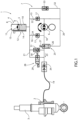
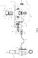
- FIG. 1 , 2 , and 3 schematically illustrate a preferred embodiment of the electric pump of the present invention in four different operating modes.
- the reference number 1 indicates, as a whole, an electric pump for operating a lifting cylinder 2, which defines part of a shock absorber 3 for a vehicle (not illustrated), and allows the lifting and lowering of a chassis (not illustrated) of the vehicle (not illustrated) to be selectively controlled.
- the electric pump 1 comprises a containing tank 4 for an operating fluid 5, in this case oil, of the cylinder 2; a feeding pump 6 to feed the operating fluid from the tank 4 to the cylinder 2; and a hydraulic circuit 7 to connect the tank 4, the pump 6, and the cylinder 2 to one another.
- the tank 4 comprises a container 8 and a floating piston 9 made of a plastic material.
- the piston 9 is mounted inside the container 8, is coupled in a fluid-tight manner with the container 8 through an annular gasket (not illustrated) mounted on the piston 9, and defines inside the container 8 a first variable volume chamber 10 containing the fluid 5 and a second variable volume chamber 11, communicating with the outside through a vent valve (not illustrated) designed to keep the chamber 11 at atmospheric pressure.
- the tank 4 is further provided with a detection device 12 to detect the position of the piston 9 along the container 8.
- the device 12 comprises at least one magnet 13 fixed to the piston 9 and a linear position sensor 14, which is mounted on the container 8, extends along the container 8, and cooperates with the magnet 13 to detect the position of the magnet 13 and, hence, of the piston 9 along the container 8.
- the pump 6 is a two-way gear pump configured to rotate both in clockwise and in counter-clockwise direction.
- the hydraulic circuit 7 comprises a first branch 15 and a second branch 16 mounted in parallel with each other between the tank 4 and the pump 6 and each provided with a respective suction valve 17, in particular a non-return valve.
- Opening of the valves 17 and, hence, flow of the operating fluid along the branches 15, 16 are controlled selectively according to the direction of rotation of the pump 6.
- the circuit 7 further comprises a third branch 18 to connect the pump 6 and a branch 19 for inflow of the fluid 5 into the lifting cylinder 2 to one another; a fourth branch 20 to connect the first branch 15 and the third branch 18 to one another; and a fifth branch 21 to connect the tank 4 and the third branch 18 to one another.
- the fourth branch 20 is connected to the first branch 15 downstream of the relative suction valve 17 in a flowing direction 22 of the fluid 5 from the tank 4 to the pump 6 along the first branch 15.
- the fifth branch 21 is connected to the third branch 18 downstream of the fourth branch 20 in a flowing direction 23 of the fluid 5 from the pump 6 to the shock absorber 3 along the third branch 18, and is also connected to the second branch 16 upstream of the relative suction valve 17 in a flowing direction 24 of the fluid 5 from the tank 4 to the pump 6 along the second branch 16.
- the circuit 7 further comprises a valve device 25, which is mounted between the third branch 18 and the fourth branch 20, and is provided with a slide valve 26 and with a spring 27 designed to move, and normally maintain, the slide valve 26 in a first operating position ( Fig. 1 ), in which the slide valve 26 allows the fluid 5 to flow from the pump 6 to the cylinder 2 and prevents the fluid 5 from flowing from the cylinder 2 to the pump 6.
- a valve device 25 which is mounted between the third branch 18 and the fourth branch 20, and is provided with a slide valve 26 and with a spring 27 designed to move, and normally maintain, the slide valve 26 in a first operating position ( Fig. 1 ), in which the slide valve 26 allows the fluid 5 to flow from the pump 6 to the cylinder 2 and prevents the fluid 5 from flowing from the cylinder 2 to the pump 6.
- the slide valve 26 is movable, due to the thrust of the fluid 5 fed by the pump 6 along the fourth branch 20 and against the action of the spring 27, from the first operating position to a second operating position ( Fig. 2 ), in which the slide valve 26 allows the fluid 5 to flow from the cylinder 2 to the pump 6.
- the circuit 7 is further provided with a solenoid valve 28, which is mounted along the fifth branch 21, and comprises a slide valve 29 and a spring 30 designed to move, and normally maintain, the slide valve 29 in a closing position of the fifth branch 21 ( Figs. 1 and 2 ).
- the solenoid valve 28 is electrically powered to move the slide valve 29 against the action of the spring 30 from the closing position to an opening position of the fifth branch 21, in which the fluid 5 flows from the cylinder 2 to the tank 4 ( Fig. 3 ).
- the circuit 7 further comprises a maximum pressure valve 31 mounted between the third branch 18 and the fifth branch 21 and connected to the third branch 18 downstream of the fourth branch 20 in the flowing direction 23 of the fluid 5 from the pump 6 to the cylinder 2.
- the circuit 7 further comprises a sixth branch 32, which connects the fourth branch 20 and the first branch 15 to one another, and is connected to the first branch 15 upstream of the relative suction valve 17 in the flowing direction 22 of the fluid 5 from the tank 4 to the pump 6 along the first branch 15.
- the circuit 7 is further provided with a discharge valve 33, which is mounted along the sixth branch 32 to allow the fluid 5 to flow back to the tank 4, and has an opening pressure that is smaller than an opening pressure of the maximum pressure valve 31.
- the setting of the opening pressure of the valve 33 depends on the maximum pressure in the branch 19 and in the branch 18 between the valve device 25 and the valve 34 and on the pilot ratio (ratio of the hydraulic thrust area) of the valve device 25 between the branch 18 and the branch 20.
- the circuit 7 finally comprises a mechanical coupling valve 34 designed to connect the third branch 18 and, hence, the electric pump 1 to the branch 19 for inflow of the fluid 5 into the cylinder 2.
- valve 34 is moved and maintained in an opening position, in which the valve 34 allows transfer of the fluid 5 between the third branch 18 and the branch 19.
- the electric pump 1 has four different operating modes, which shall now be described with reference to Figs. 1 , 2 , and 3 and starting from an instant in which the valve device 25 is arranged in its first operating position and the solenoid valve 28 is arranged in its closing position.
- the pump 6 is operated counter-clockwise so as to allow:
- the fluid 5 is pressurized by the pump 6 and fed along the third branch 18, through the valve 34, and to the cylinder 2 and allows the suction valve 17 of the second branch 16 to be maintained closed.
- a second operating mode illustrated in Fig. 1 and used to block the chassis (not illustrated) of the vehicle (not illustrated) in a raised position the pump 6 is deactivated, return of the pressurized fluid 5 fed to the cylinder 2 is prevented both by the valve device 25, and by the solenoid valve 28, and the pressurized fluid 5 is contained between the cylinder 2, the valve device 25, and the solenoid valve 28.
- the pressurized fluid 5 is fed by the pump 6 along the fourth branch 20, allows the suction valve 17 of the first branch 15 to be maintained closed, and also allows the slide valve 26 of the valve device 25 to move from its first operating position into its second operating position.
- the fluid 5 is fed firstly from the cylinder 2 to the pump 6 along the third branch 18 and then from the pump 6 into the fourth branch 20 so as to open the discharge valve 33 and flow back once again into the tank 4.
- the discharge valve 33 is configured so as to avoid instability and noise generated by discharge of the fluid 5 into the tank 4.
- a fourth operating mode illustrated in Fig. 3 and used to lower the chassis (not illustrated) of the vehicle (not illustrated) with a relatively high descent speed the pump 6 is deactivated, the slide valve 26 for distribution of the valve device 25 is moved again by the spring 27 into its first operating position so as to prevent the fluid 5 from flowing back into the pump 6 along the third branch 18, and the solenoid valve 28 is activated and moved into its opening position so as to allow the fluid 5 to flow back from the cylinder 2 into the tank 4 along the fifth branch 21.
- the electric pump 1 has some advantages mainly deriving from the fact that:
Landscapes
- Engineering & Computer Science (AREA)
- Mechanical Engineering (AREA)
- General Engineering & Computer Science (AREA)
- Vehicle Body Suspensions (AREA)
Abstract
Description
- This patent application claims priority from
Italian patent application no. 102022000014926 filed on July 15, 2022 - The present invention relates to an electric pump, in particular for operating a lifting cylinder of a shock absorber for vehicles.
- In general, the present invention is particularly advantageous for application in an electric pump for feeding and operating a hydraulic actuator cylinder of a vehicle.
- In particular, the present invention relates to an electric pump of the type comprising a containing tank for an operating fluid, in the case in question oil; a feeding pump to feed the operating fluid from the containing tank to a user, in particular the lifting cylinder of the shock absorber of a vehicle; an electric motor for operating the feeding pump; and a hydraulic circuit to connect the containing tank, the feeding pump, and the user to one another.
- The containing tank accommodates, on the inside, the operating fluid, and is connected to a compressed air pneumatic device designed to feed the operating fluid to the outside of the containing tank.
- Known electric pumps of the type described above have some problems mainly deriving from the fact that the containing tank is a pressurized containing tank, is relatively complex and costly, and requires isolation of at least part of the electric motor from the operating fluid.
- When the pressurized containing tank is replaced with a containing tank with a free surface, known electric pumps of the type described above have some problems, mainly deriving from the fact that the use of a containing tank with a free surface causes problems of suction of the operating fluid in certain driving conditions of the vehicle and from the presence of air in the operating fluid fed into the hydraulic circuit.
- The object of the present invention is to provide an electric pump, in particular for operating a lifting cylinder of a shock absorber for vehicles, which solves the problems described above and which is simple and inexpensive to implement.
- According to the present invention, there is provided an electric pump, in particular for operating a lifting cylinder of a shock absorber for vehicles, as claimed in the appended claims.
- The present invention will now be described with reference to the accompanying drawings, which show a non-limiting example of embodiment thereof, wherein:
Figs. 1 ,2 , and3 schematically illustrate a preferred embodiment of the electric pump of the present invention in four different operating modes. - With reference to
Figs. 1 ,2 , and3 , thereference number 1 indicates, as a whole, an electric pump for operating alifting cylinder 2, which defines part of ashock absorber 3 for a vehicle (not illustrated), and allows the lifting and lowering of a chassis (not illustrated) of the vehicle (not illustrated) to be selectively controlled. - The
electric pump 1 comprises a containing tank 4 for anoperating fluid 5, in this case oil, of thecylinder 2; a feeding pump 6 to feed the operating fluid from the tank 4 to thecylinder 2; and ahydraulic circuit 7 to connect the tank 4, the pump 6, and thecylinder 2 to one another. - The tank 4 comprises a container 8 and a
floating piston 9 made of a plastic material. - The
piston 9 is mounted inside the container 8, is coupled in a fluid-tight manner with the container 8 through an annular gasket (not illustrated) mounted on thepiston 9, and defines inside the container 8 a firstvariable volume chamber 10 containing thefluid 5 and a secondvariable volume chamber 11, communicating with the outside through a vent valve (not illustrated) designed to keep thechamber 11 at atmospheric pressure. - The tank 4 is further provided with a
detection device 12 to detect the position of thepiston 9 along the container 8. - In this case, the
device 12 comprises at least onemagnet 13 fixed to thepiston 9 and alinear position sensor 14, which is mounted on the container 8, extends along the container 8, and cooperates with themagnet 13 to detect the position of themagnet 13 and, hence, of thepiston 9 along the container 8. - The pump 6 is a two-way gear pump configured to rotate both in clockwise and in counter-clockwise direction.
- The
hydraulic circuit 7 comprises afirst branch 15 and asecond branch 16 mounted in parallel with each other between the tank 4 and the pump 6 and each provided with arespective suction valve 17, in particular a non-return valve. - Opening of the
valves 17 and, hence, flow of the operating fluid along thebranches - The
circuit 7 further comprises athird branch 18 to connect the pump 6 and abranch 19 for inflow of thefluid 5 into the liftingcylinder 2 to one another; afourth branch 20 to connect thefirst branch 15 and thethird branch 18 to one another; and afifth branch 21 to connect the tank 4 and thethird branch 18 to one another. - The
fourth branch 20 is connected to thefirst branch 15 downstream of therelative suction valve 17 in a flowingdirection 22 of thefluid 5 from the tank 4 to the pump 6 along thefirst branch 15. - The
fifth branch 21 is connected to thethird branch 18 downstream of thefourth branch 20 in a flowingdirection 23 of thefluid 5 from the pump 6 to the shock absorber 3 along thethird branch 18, and is also connected to thesecond branch 16 upstream of therelative suction valve 17 in a flowingdirection 24 of thefluid 5 from the tank 4 to the pump 6 along thesecond branch 16. - The
circuit 7 further comprises avalve device 25, which is mounted between thethird branch 18 and thefourth branch 20, and is provided with aslide valve 26 and with aspring 27 designed to move, and normally maintain, theslide valve 26 in a first operating position (Fig. 1 ), in which theslide valve 26 allows thefluid 5 to flow from the pump 6 to thecylinder 2 and prevents thefluid 5 from flowing from thecylinder 2 to the pump 6. - The
slide valve 26 is movable, due to the thrust of thefluid 5 fed by the pump 6 along thefourth branch 20 and against the action of thespring 27, from the first operating position to a second operating position (Fig. 2 ), in which theslide valve 26 allows thefluid 5 to flow from thecylinder 2 to the pump 6. - The
circuit 7 is further provided with asolenoid valve 28, which is mounted along thefifth branch 21, and comprises aslide valve 29 and aspring 30 designed to move, and normally maintain, theslide valve 29 in a closing position of the fifth branch 21 (Figs. 1 and2 ). - The
solenoid valve 28 is electrically powered to move theslide valve 29 against the action of thespring 30 from the closing position to an opening position of thefifth branch 21, in which thefluid 5 flows from thecylinder 2 to the tank 4 (Fig. 3 ). - The
circuit 7 further comprises amaximum pressure valve 31 mounted between thethird branch 18 and thefifth branch 21 and connected to thethird branch 18 downstream of thefourth branch 20 in the flowingdirection 23 of thefluid 5 from the pump 6 to thecylinder 2. - The
circuit 7 further comprises asixth branch 32, which connects thefourth branch 20 and thefirst branch 15 to one another, and is connected to thefirst branch 15 upstream of therelative suction valve 17 in the flowingdirection 22 of thefluid 5 from the tank 4 to the pump 6 along thefirst branch 15. - The
circuit 7 is further provided with adischarge valve 33, which is mounted along thesixth branch 32 to allow thefluid 5 to flow back to the tank 4, and has an opening pressure that is smaller than an opening pressure of themaximum pressure valve 31. - The setting of the opening pressure of the
valve 33 depends on the maximum pressure in thebranch 19 and in thebranch 18 between thevalve device 25 and thevalve 34 and on the pilot ratio (ratio of the hydraulic thrust area) of thevalve device 25 between thebranch 18 and thebranch 20. - The
circuit 7 finally comprises amechanical coupling valve 34 designed to connect thethird branch 18 and, hence, theelectric pump 1 to thebranch 19 for inflow of thefluid 5 into thecylinder 2. - Following connection to the
branch 19, thevalve 34 is moved and maintained in an opening position, in which thevalve 34 allows transfer of thefluid 5 between thethird branch 18 and thebranch 19. - The
electric pump 1 has four different operating modes, which shall now be described with reference toFigs. 1 ,2 , and3 and starting from an instant in which thevalve device 25 is arranged in its first operating position and thesolenoid valve 28 is arranged in its closing position. - With reference to
Fig. 1 , according to a first operating mode used to feed thefluid 5 to thecylinder 2 and, hence, lift the chassis (not illustrated) of the vehicle (not illustrated), the pump 6 is operated counter-clockwise so as to allow: - the vacuum pressure generated by the pump 6 to open the
valve 17 of thefirst branch 15 and to draw thefluid 5 into the pump 6; and - the difference in pressure between the
chamber 11 and thechamber 10 to maintain thepiston 9 in contact with thefluid 5 and to facilitate suction of the pump 6. - The
fluid 5 is pressurized by the pump 6 and fed along thethird branch 18, through thevalve 34, and to thecylinder 2 and allows thesuction valve 17 of thesecond branch 16 to be maintained closed. - In a second operating mode illustrated in
Fig. 1 and used to block the chassis (not illustrated) of the vehicle (not illustrated) in a raised position, the pump 6 is deactivated, return of the pressurizedfluid 5 fed to thecylinder 2 is prevented both by thevalve device 25, and by thesolenoid valve 28, and the pressurizedfluid 5 is contained between thecylinder 2, thevalve device 25, and thesolenoid valve 28. - According to a third operating mode illustrated in
Fig. 2 and used to lower the chassis (not illustrated) of the vehicle (not illustrated) with a relatively low descent speed depending on the rotation speed of the pump 6, the pump 6 is operated clockwise so as to allow: - the vacuum pressure generated by the pump 6 to open the
valve 17 of thesecond branch 16 and to draw thefluid 5 into the pump 6; and - the difference in pressure between the
chamber 11 and thechamber 10 to maintain thepiston 9 in contact with thefluid 5 and to facilitate suction of the pump 6. - The pressurized
fluid 5 is fed by the pump 6 along thefourth branch 20, allows thesuction valve 17 of thefirst branch 15 to be maintained closed, and also allows theslide valve 26 of thevalve device 25 to move from its first operating position into its second operating position. - Once the
slide valve 26 has been moved into its second operating position, thefluid 5 is fed firstly from thecylinder 2 to the pump 6 along thethird branch 18 and then from the pump 6 into thefourth branch 20 so as to open thedischarge valve 33 and flow back once again into the tank 4. - In this regard it should be specified that the
discharge valve 33 is configured so as to avoid instability and noise generated by discharge of thefluid 5 into the tank 4. - According to a fourth operating mode illustrated in
Fig. 3 and used to lower the chassis (not illustrated) of the vehicle (not illustrated) with a relatively high descent speed, the pump 6 is deactivated, theslide valve 26 for distribution of thevalve device 25 is moved again by thespring 27 into its first operating position so as to prevent thefluid 5 from flowing back into the pump 6 along thethird branch 18, and thesolenoid valve 28 is activated and moved into its opening position so as to allow thefluid 5 to flow back from thecylinder 2 into the tank 4 along thefifth branch 21. - The
electric pump 1 has some advantages mainly deriving from the fact that: - the
piston 9 is moved along the tank 4 only by a force generated by the combination of the suction pressure acting in thechamber 10 with the atmospheric pressure acting in thechamber 11 and without requiring any auxiliary thrust device, such as a spring; - the containing tank 4 at atmospheric pressure is relatively simple and inexpensive;
- the fluid-tight coupling of the
floating piston 9 with the container 8 allows elimination of the presence of air in thechamber 10 and, hence, in thefluid 5; - the
detection device 12 allows detection of the position of thefloating piston 9, the volume offluid 5 contained in the tank 4, and, hence, the stroke of thelifting cylinder 2 of theshock absorber 2; - the
solenoid valve 28 is normally arranged in its closing position and is only electrically powered in the operating mode used to lower the chassis (not illustrated) of the vehicle (not illustrated) with a relatively high descent speed; - the raised position of the chassis (not illustrated) of the vehicle (not illustrated) is maintained in a relatively simple manner by deactivating the pump 6 and the
solenoid valve 28; and - the descent speed of the chassis (not illustrated) of the vehicle (not illustrated) in the aforesaid third operating mode is controlled selectively in a relatively simple and inexpensive manner by means of the rotation speed of the pump 6.
Claims (16)
- - An electric pump, in particular for operating a lifting cylinder (2) of a shock absorber (3) for vehicles, comprising a containing tank (4) for an operating fluid (5); a feeding pump (6) to feed the operating fluid (5) from the containing tank (4) to a user, in particular the lifting cylinder (2) of the shock absorber (3) for vehicles; and a hydraulic circuit (7) to connect the containing tank (4), the feeding pump (6) and the user to one another; and characterized in that the containing tank (4) accommodates, on the inside, a floating piston (9) designed to divide the containing tank (4) into a first chamber (10) to contain the operating fluid (5) and a second chamber (11) communicating with the outside and, hence, at atmospheric pressure.
- - The electric pump according to claim 1, wherein the floating piston (9) is provided with a gasket to be coupled to the containing tank (4) in a fluid-tight manner and to divide said first and second chamber (10, 11) from one another in a fluid-tight manner.
- - The electric pump according to claim 1 or 2 and further comprising a detection device (12) to detect the position of the floating piston (9) along the containing tank (4).
- - The electric pump according to claim 3, wherein the detection device (12) comprises at least one magnet (13) mounted on the floating piston (9) and a linear position sensor (14) mounted on the containing tank (4) and associated with the magnet (13).
- - The electric pump according to any one of the preceding claims, wherein the containing tank (4) and/or the floating piston (9) are made of a plastic material.
- - The electric pump according to any one of the preceding claims, wherein the hydraulic circuit (7) comprises a first branch (15) and a second branch (16), which are mounted in parallel to one another between the containing tank (4) and the feeding pump (6) and are each provided with a respective suction valve (17), in particular a non-return valve; the feeding pump (6) being a two-way feeding pump to selectively control the suction of the operating fluid (5) along one of said first and second branch (15, 16).
- - The electric pump according to claim 6, wherein the hydraulic circuit (7) further comprises a third branch (18) to connect the feeding pump (6) and the user to one another, a fourth branch (20) to connect the first branch (15) and the third branch (18) to one another, and a fifth branch (21) to connect the containing tank (4) and the third branch (18) to one another.
- - The electric pump according to claim 7, wherein the fourth branch (20) is connected to the first branch (15) downstream of the relative suction valve (17) in a flowing direction (22) of the operating fluid (5) from the containing tank (4) to the feeding pump (6) along the first branch (15).
- - The electric pump according to claim 7 or 8, wherein the fifth branch (21) is connected to the third branch (18) downstream of the fourth branch (20) in a flowing direction (23) of the operating fluid (5) from the feeding pump (6) to the user along the third branch (18) and is further connected to the second branch (16) upstream of the relative suction valve (17) in a flowing direction (24) of the operating fluid (5) from the containing tank (4) to the feeding pump (6) along the second branch (16).
- - The electric pump according to any one of the claims from 7 to 9, wherein the hydraulic circuit (7) further comprises a valve device (25) mounted between the third branch (18) and the fourth branch (20) and provided with a slide valve (26), which is normally arranged in a first operating position, in which the slide valve (26) allows the operating fluid (5) to flow from the feeding pump (6) to the user and prevents the operating fluid (5) from flowing from the user to the feeding pump (6), and is movable, due to the thrust of the operating fluid (5) fed by the feeding pump (6) along the fourth branch (20), to a second operating position, in which the slide valve (26) allows the operating fluid (5) to flow from the user to the feeding pump (6).
- - The electric pump according to any one of the claims from 7 to 10, wherein the hydraulic circuit (7) further comprises a solenoid valve (28), which is mounted along the fifth branch (21), is normally arranged in a closing position closing the fifth branch (21) and is operated so as to move to an opening position opening the fifth branch (21) in order to allow the operating fluid (5) to flow from the user to the containing tank (4).
- - The electric pump according to any one of the claims from 7 to 11, wherein the hydraulic circuit (7) further comprises a maximum pressure valve (31) mounted between the third branch (18) and the fifth branch (21) and connected to the third branch (18) downstream of the fourth branch (20) in the flowing direction (23) of the operating fluid (5) from the feeding pump (6) to the user along the third branch (18).
- - The electric pump according to any one of the claims from 7 to 12, wherein the hydraulic circuit (7) further comprises a sixth branch (32) to connect the fourth branch (20) and the first branch (15) to one another; the sixth branch (32) being connected to the first branch (15) upstream of the relative suction valve (17) in the flowing direction (22) of the operating fluid (5) from the containing tank (4) to the feeding pump (6) along the first branch (15).
- - The electric pump according to claim 13, wherein the hydraulic circuit (7) further comprises a discharge valve (33) mounted along the sixth branch (32) in order to allow the operating fluid (5) to flow back to the containing tank (4).
- - The electric pump according to claim 14, when it depends on claim 12, wherein the discharge valve (33) has an opening pressure that is smaller than an opening pressure of the maximum pressure valve (31), in particular dependent on the maximum pressure in the third branch (18) downstream of the valve device (25) in the flowing direction (23) of the operating fluid (5) from the feeding pump (6) to the user and on the pilot ratio of the valve device (25) between the third branch (18) and the fourth branch (20).
- - The electric pump according to any one of the preceding claims, wherein the floating piston (9) is configured to move inside the containing tank (4) only under the thrust of a force generated by the combination of suction pressure acting in the first chamber (10) with the atmospheric pressure acting in the second chamber (11).
Applications Claiming Priority (1)
| Application Number | Priority Date | Filing Date | Title |
|---|---|---|---|
| IT202200014926 | 2022-07-15 |
Publications (1)
| Publication Number | Publication Date |
|---|---|
| EP4306800A1 true EP4306800A1 (en) | 2024-01-17 |
Family
ID=83505613
Family Applications (1)
| Application Number | Title | Priority Date | Filing Date |
|---|---|---|---|
| EP23184939.9A Pending EP4306800A1 (en) | 2022-07-15 | 2023-07-12 | Electric pump, in particular for operating a lifting cylinder of a shock absorber for vehicles |
Country Status (1)
| Country | Link |
|---|---|
| EP (1) | EP4306800A1 (en) |
Citations (4)
| Publication number | Priority date | Publication date | Assignee | Title |
|---|---|---|---|---|
| US20170037923A1 (en) * | 2014-04-16 | 2017-02-09 | Alain BORDIER | Hydraulic shock absorber with compression filtering |
| EP3276172A1 (en) * | 2016-07-29 | 2018-01-31 | DROPSA S.p.A. | Pump provided with a reservoir of a lubricant |
| DE102018215132A1 (en) * | 2018-09-06 | 2020-03-12 | Ford Global Technologies, Llc | High pressure pump for a fuel supply to an internal combustion engine |
| JP2020104833A (en) * | 2018-12-27 | 2020-07-09 | 株式会社アドヴィックス | Vehicle brake apparatus |
-
2023
- 2023-07-12 EP EP23184939.9A patent/EP4306800A1/en active Pending
Patent Citations (4)
| Publication number | Priority date | Publication date | Assignee | Title |
|---|---|---|---|---|
| US20170037923A1 (en) * | 2014-04-16 | 2017-02-09 | Alain BORDIER | Hydraulic shock absorber with compression filtering |
| EP3276172A1 (en) * | 2016-07-29 | 2018-01-31 | DROPSA S.p.A. | Pump provided with a reservoir of a lubricant |
| DE102018215132A1 (en) * | 2018-09-06 | 2020-03-12 | Ford Global Technologies, Llc | High pressure pump for a fuel supply to an internal combustion engine |
| JP2020104833A (en) * | 2018-12-27 | 2020-07-09 | 株式会社アドヴィックス | Vehicle brake apparatus |
Similar Documents
| Publication | Publication Date | Title |
|---|---|---|
| US3273468A (en) | Hydraulic system with regenerative position | |
| US6851350B2 (en) | Valve device for a control cylinder | |
| US11491866B2 (en) | Evaporative emissions fuel tank venting system with pressure relief | |
| EP2848819A1 (en) | Actuator | |
| US3583432A (en) | Pilot operated pressure-vacuum relief valves | |
| CN101778747A (en) | Brake system for a vehicle | |
| CN110030182A (en) | Piston pump for the pressure medium in discharge pressure medium loop | |
| US11035391B2 (en) | Hydrostatic linear drive system | |
| US3828556A (en) | Hydraulic actuator | |
| US3605556A (en) | Booster pump | |
| US3987625A (en) | Combined sensor and control | |
| KR100906434B1 (en) | Conversion valve device and hydraulic cylinder device | |
| CN102401127A (en) | Hydraulic transmission mechanism | |
| US8833391B2 (en) | Valve arrangement | |
| US9797508B2 (en) | Double-acting shift cylinder actuating assembly | |
| US2501054A (en) | Unloader for pumps | |
| US20180372083A1 (en) | Hydraulic diaphragm control | |
| US6336324B1 (en) | Slewing gear control system with braking and control valves | |
| US5174189A (en) | Fluid control apparatus | |
| US12265405B2 (en) | Arrangement and manipulation system, and method for manipulating the flow of a fluid | |
| MXPA01003109A (en) | AIR DRIVEN HYDRAULIC CAT WITH AUTOMATIC CLOSING AIR CONTROL LOAD DETECTION. | |
| US3811471A (en) | Dual pressure relief valve system | |
| DE19714513A1 (en) | Installation for supplying compressed air to vehicles | |
| CA2028642A1 (en) | Hydraulic dry valve control apparatus | |
| EP3758967A1 (en) | Evaporative emissions fuel tank venting system with drain pump |
Legal Events
| Date | Code | Title | Description |
|---|---|---|---|
| PUAI | Public reference made under article 153(3) epc to a published international application that has entered the european phase |
Free format text: ORIGINAL CODE: 0009012 |
|
| STAA | Information on the status of an ep patent application or granted ep patent |
Free format text: STATUS: THE APPLICATION HAS BEEN PUBLISHED |
|
| AK | Designated contracting states |
Kind code of ref document: A1 Designated state(s): AL AT BE BG CH CY CZ DE DK EE ES FI FR GB GR HR HU IE IS IT LI LT LU LV MC ME MK MT NL NO PL PT RO RS SE SI SK SM TR |
|
| STAA | Information on the status of an ep patent application or granted ep patent |
Free format text: STATUS: REQUEST FOR EXAMINATION WAS MADE |
|
| 17P | Request for examination filed |
Effective date: 20240618 |
|
| RBV | Designated contracting states (corrected) |
Designated state(s): AL AT BE BG CH CY CZ DE DK EE ES FI FR GB GR HR HU IE IS IT LI LT LU LV MC ME MK MT NL NO PL PT RO RS SE SI SK SM TR |
|
| STAA | Information on the status of an ep patent application or granted ep patent |
Free format text: STATUS: EXAMINATION IS IN PROGRESS |
|
| 17Q | First examination report despatched |
Effective date: 20250508 |