EP4306774A1 - Cooling device for rotor assembly - Google Patents
Cooling device for rotor assembly Download PDFInfo
- Publication number
- EP4306774A1 EP4306774A1 EP23184987.8A EP23184987A EP4306774A1 EP 4306774 A1 EP4306774 A1 EP 4306774A1 EP 23184987 A EP23184987 A EP 23184987A EP 4306774 A1 EP4306774 A1 EP 4306774A1
- Authority
- EP
- European Patent Office
- Prior art keywords
- airflow
- nozzle
- rotor assembly
- inlets
- cooling device
- Prior art date
- Legal status (The legal status is an assumption and is not a legal conclusion. Google has not performed a legal analysis and makes no representation as to the accuracy of the status listed.)
- Pending
Links
Images



Classifications
-
- F—MECHANICAL ENGINEERING; LIGHTING; HEATING; WEAPONS; BLASTING
- F01—MACHINES OR ENGINES IN GENERAL; ENGINE PLANTS IN GENERAL; STEAM ENGINES
- F01D—NON-POSITIVE DISPLACEMENT MACHINES OR ENGINES, e.g. STEAM TURBINES
- F01D25/00—Component parts, details, or accessories, not provided for in, or of interest apart from, other groups
- F01D25/08—Cooling; Heating; Heat-insulation
-
- B—PERFORMING OPERATIONS; TRANSPORTING
- B23—MACHINE TOOLS; METAL-WORKING NOT OTHERWISE PROVIDED FOR
- B23P—METAL-WORKING NOT OTHERWISE PROVIDED FOR; COMBINED OPERATIONS; UNIVERSAL MACHINE TOOLS
- B23P11/00—Connecting or disconnecting metal parts or objects by metal-working techniques not otherwise provided for
- B23P11/02—Connecting or disconnecting metal parts or objects by metal-working techniques not otherwise provided for by first expanding and then shrinking or vice versa, e.g. by using pressure fluids; by making force fits
- B23P11/025—Connecting or disconnecting metal parts or objects by metal-working techniques not otherwise provided for by first expanding and then shrinking or vice versa, e.g. by using pressure fluids; by making force fits by using heat or cold
-
- B—PERFORMING OPERATIONS; TRANSPORTING
- B23—MACHINE TOOLS; METAL-WORKING NOT OTHERWISE PROVIDED FOR
- B23P—METAL-WORKING NOT OTHERWISE PROVIDED FOR; COMBINED OPERATIONS; UNIVERSAL MACHINE TOOLS
- B23P15/00—Making specific metal objects by operations not covered by a single other subclass or a group in this subclass
- B23P15/006—Making specific metal objects by operations not covered by a single other subclass or a group in this subclass turbine wheels
-
- F—MECHANICAL ENGINEERING; LIGHTING; HEATING; WEAPONS; BLASTING
- F01—MACHINES OR ENGINES IN GENERAL; ENGINE PLANTS IN GENERAL; STEAM ENGINES
- F01D—NON-POSITIVE DISPLACEMENT MACHINES OR ENGINES, e.g. STEAM TURBINES
- F01D25/00—Component parts, details, or accessories, not provided for in, or of interest apart from, other groups
- F01D25/08—Cooling; Heating; Heat-insulation
- F01D25/12—Cooling
-
- F—MECHANICAL ENGINEERING; LIGHTING; HEATING; WEAPONS; BLASTING
- F01—MACHINES OR ENGINES IN GENERAL; ENGINE PLANTS IN GENERAL; STEAM ENGINES
- F01D—NON-POSITIVE DISPLACEMENT MACHINES OR ENGINES, e.g. STEAM TURBINES
- F01D25/00—Component parts, details, or accessories, not provided for in, or of interest apart from, other groups
- F01D25/28—Supporting or mounting arrangements, e.g. for turbine casing
- F01D25/285—Temporary support structures, e.g. for testing, assembling, installing, repairing; Assembly methods using such structures
-
- F—MECHANICAL ENGINEERING; LIGHTING; HEATING; WEAPONS; BLASTING
- F05—INDEXING SCHEMES RELATING TO ENGINES OR PUMPS IN VARIOUS SUBCLASSES OF CLASSES F01-F04
- F05D—INDEXING SCHEME FOR ASPECTS RELATING TO NON-POSITIVE-DISPLACEMENT MACHINES OR ENGINES, GAS-TURBINES OR JET-PROPULSION PLANTS
- F05D2220/00—Application
- F05D2220/30—Application in turbines
- F05D2220/32—Application in turbines in gas turbines
-
- F—MECHANICAL ENGINEERING; LIGHTING; HEATING; WEAPONS; BLASTING
- F05—INDEXING SCHEMES RELATING TO ENGINES OR PUMPS IN VARIOUS SUBCLASSES OF CLASSES F01-F04
- F05D—INDEXING SCHEME FOR ASPECTS RELATING TO NON-POSITIVE-DISPLACEMENT MACHINES OR ENGINES, GAS-TURBINES OR JET-PROPULSION PLANTS
- F05D2230/00—Manufacture
- F05D2230/60—Assembly methods
-
- F—MECHANICAL ENGINEERING; LIGHTING; HEATING; WEAPONS; BLASTING
- F05—INDEXING SCHEMES RELATING TO ENGINES OR PUMPS IN VARIOUS SUBCLASSES OF CLASSES F01-F04
- F05D—INDEXING SCHEME FOR ASPECTS RELATING TO NON-POSITIVE-DISPLACEMENT MACHINES OR ENGINES, GAS-TURBINES OR JET-PROPULSION PLANTS
- F05D2260/00—Function
- F05D2260/20—Heat transfer, e.g. cooling
- F05D2260/201—Heat transfer, e.g. cooling by impingement of a fluid
Definitions
- Exemplary embodiments of the present disclosure pertain to the art of gas turbine engines, and in particular to assembly of rotors of gas turbine engines.
- Rotor assemblies for example high pressure compressor (HPC) rotor assemblies, of gas turbine engines include a plurality of rotor stages assembled into a stack along a stacking axis. The assembly requires heating of a rotor to be installed to the rotor stack to allow for engagement of "snap" features of adjacent rotor stages. Before proceeding with the next subsequent assembly, the rotor stack must then be cooled. Typically, the rotor stack is allowed to cool naturally in the assembly environment, which takes approximately one hour. Over the entire rotor assembly operation, cooling process of the rotor stack can account for approximately 50% of the total assembly time of the rotor assembly, or about 6 hours.
- HPC high pressure compressor
- a cooling device for a rotor assembly of a gas turbine engine includes an airflow nozzle configured to be installed at a cooling location of the rotor assembly.
- the airflow nozzle extends entirely around a circumference of the rotor assembly and includes a plurality of airflow inlets and a nozzle outlet to direct an airflow toward the cooling location.
- An airflow source is operably connected to the plurality of airflow inlets.
- one or more support rods are operably connected to the airflow nozzle to position the airflow nozzle.
- the one or more support rods are adjustable to change a position of the airflow nozzle.
- a manifold distributes the airflow from the airflow source to the plurality of airflow inlets.
- an airflow valve is operably connected to each airflow inlet of the plurality of airflow inlets to independently control the airflow through the airflow inlet.
- the airflow nozzle tapers in width between the plurality of airflow inlets and the nozzle outlet.
- a targeting device aids in positioning the nozzle outlet relative to the selected cooling location.
- one or more anemometers monitor the airflow from the nozzle outlet.
- the airflow is uniform around a circumference of the nozzle outlet.
- the airflow nozzle includes a plurality of circumferential nozzle segments.
- a method of assembling a rotor assembly comprising two or more rotor stages includes heating one or more of a first rotor stage or a second rotor stage of the rotor assembly, assembling the first rotor stage to the second rotor stage, and installing a cooling device circumferentially around a selected cooling location of the rotor assembly.
- the cooling device includes an airflow nozzle configured to be installed at a cooling location of the rotor assembly.
- the airflow nozzle extends entirely around a circumference of the rotor assembly and includes a plurality of airflow inlets and a nozzle outlet.
- An airflow source is operably connected to the plurality of airflow inlets. An airflow is urged from the airflow source into the airflow nozzle through the plurality of airflow inlets and out of the nozzle outlet toward the selected cooling location.
- the airflow nozzle is supported via one or more support rods operably connected to the airflow nozzle.
- the one or more support rods are adjusted to change a position of the airflow nozzle.
- the airflow is distributed from the airflow source to the plurality of airflow inlets via a manifold located between the airflow source and the plurality of airflow inlets.
- the airflow through the plurality of airflow inlets is independently controlled via an airflow valve operably connected to each airflow inlet of the plurality of airflow inlets.
- the airflow nozzle tapers in width between the plurality of airflow inlets and the nozzle outlet.
- a targeting device is positioned to aid in positioning the nozzle outlet relative to the selected cooling location.
- the airflow from the nozzle outlet is monitored via one or more anemometers.
- the airflow is uniform around a circumference of the nozzle outlet.
- the airflow nozzle includes a plurality of circumferential nozzle segments.
- FIG. 1 schematically illustrates a rotor assembly 10 on a rotor assembly fixture 12.
- the rotor assembly 10 includes a plurality of rotor stages 14 stacked along a stacking axis 16.
- adjacent rotor stages 14 are assembled via a radial mating snap connection 18, as shown in FIG. 2 , between the adjacent rotor stages 14.
- the rotor assembly fixture 12 includes a fixture plate 20 in which the rotor stages 14 are stacked and a stacking rod 22 defining the stacking axis 16 of the rotor assembly 10.
- an upper plate 24 is utilized to hold and apply pressure along the stacking axis 16 to the rotor assembly 10 on the rotor assembly fixture 12 during the assembly process.
- the rotor cooling device 26 includes an air nozzle 28 the extends circumferentially around the rotor assembly 10.
- the air nozzle 28 is formed from a plurality of nozzle segments 30 joined to form a circumferential ring air nozzle 28 extending entirely circumferentially around the rotor assembly 10 with a nozzle outlet 32 (shown in FIG. 5 ) to direct an airflow 34 at a selected location of the rotor assembly 10.
- the nozzle outlet 32 is a full circumferential ring around the rotor assembly 10.
- the nozzle segments 30 each have segment end walls at each circumferential end of the nozzle segment 30.
- the air nozzle 28 is supported by a plurality of support rods 36 extending from the fixture plate 20.
- the support rods 36 are adjustable or replaceable to adjust the nozzle height 38 of the air nozzle 28 relative to the fixture plate 20 so that the airflow 34 is directed from the nozzle outlet 32 to a selected location of the rotor assembly 10 to cool the selected location, for example, the snap connection 18 location of the rotor assembly 10. While in the embodiments described herein support rods 36 are utilized to support the air nozzle 28, one skilled in the art will readily appreciate that the air nozzle 28 may be supported by, for example, robotic arms or structures or the like.
- the airflow 34 is directed out of the air nozzle 28 from an air source, for example, a compressed air source 40. From the compressed air source 40, the airflow 34 proceeds through a manifold 42, which splits the airflow 34 into a plurality of airflow streams corresponding to a number of airflow inlets 44 into the airflow nozzle 28.
- an air source for example, a compressed air source 40.
- the airflow 34 proceeds through a manifold 42, which splits the airflow 34 into a plurality of airflow streams corresponding to a number of airflow inlets 44 into the airflow nozzle 28.
- the airflow nozzle 28 includes a nozzle channel 46 which extends circumferentially around the airflow nozzle 28 to distribute the airflow 34 uniformly from the plurality of airflow inlets 44, which in some embodiments is eight equally-spaced airflow inlets 44.
- the nozzle channel 46 tapers radially from a relatively wide axial channel width 48 at the airflow inlets 44 to a relatively axially narrow channel width 48 at the nozzle outlet 32. This tapering accelerates the airflow 34 and allows the airflow 34 to be more uniformly delivered to the selected location of the rotor assembly 10.
- the nozzle height 38 may be monitored via a targeting device such as a laser pointer 60 or the like located on the air nozzle 28, which is directed toward the rotor assembly 10 as a visual guide on the location at which the airflow 34 is directed.
- the nozzle 28 then may be axially moved via adjustment or replacement of the support rods 36 until the laser pointer 60 is directed at the selected location.
- the airflow 34 into the airflow nozzle 28 may be controlled by airflow valves 50 located along airflow lines 52 between the manifold 42 and the respective airflow inlets 44.
- the airflow valves 50 may be adjusted individually, so that airflow into each of the airflow inlets 44 is independently controlled. This allows for circumferential adjustment of the airflow 34 into the airflow nozzle 28 and out of the nozzle outlet 32.
- the airflow 34 exiting the nozzle outlet 32 may be monitored by, for example, one or more anemometers 52 located at circumferential locations around the nozzle outlet 32. This may be achieved by monitoring the airflow 34 with the one or more anemometers 54 (shown in FIG. 5 ) and adjusting the airflow 34 as needed via the airflow valves 50.
- FIG. 6 illustrated is a schematic of a process for assembling a rotor assembly 10.
- the mating rotor stage 10 is heated.
- a rotor stage 10 is installed onto the rotor assembly 14 at step 102.
- the rotor cooling device 26 is installed, and the nozzle outlet 32 is directed at the selected cooling location, for example, the snap connection 18 of the installed rotor stage 14 to the rotor assembly 10.
- the airflow valves 50 are opened at step 106 to direct airflow 34 through the nozzle outlet 32 to the selected cooling location to cool the rotor assembly 10. This process is then repeated as subsequent rotor stages 14 are installed to the rotor assembly 10.
- the use of the airflow nozzle 28 extending entirely circumferentially around the rotor assembly 10 allows for a uniform airflow 34 to be precisely directed at a desired cooling location of the rotor assembly 10, and accelerates the cooling process which will result in a reduction in time required for rotor assembly, while also ensuring that the roundness and squareness requirements of the final rotor assembly 14 are not affected by this cooling process.
Landscapes
- Engineering & Computer Science (AREA)
- Mechanical Engineering (AREA)
- General Engineering & Computer Science (AREA)
- Turbine Rotor Nozzle Sealing (AREA)
- Chemical & Material Sciences (AREA)
- Combustion & Propulsion (AREA)
Abstract
Description
- Exemplary embodiments of the present disclosure pertain to the art of gas turbine engines, and in particular to assembly of rotors of gas turbine engines.
- Rotor assemblies, for example high pressure compressor (HPC) rotor assemblies, of gas turbine engines include a plurality of rotor stages assembled into a stack along a stacking axis. The assembly requires heating of a rotor to be installed to the rotor stack to allow for engagement of "snap" features of adjacent rotor stages. Before proceeding with the next subsequent assembly, the rotor stack must then be cooled. Typically, the rotor stack is allowed to cool naturally in the assembly environment, which takes approximately one hour. Over the entire rotor assembly operation, cooling process of the rotor stack can account for approximately 50% of the total assembly time of the rotor assembly, or about 6 hours.
- Due to tight roundness and squareness requirements of the final rotor assembly, previous attempts to cool the rotor stack with, for example, a fan, have had limited or no success.
- In one embodiment, a cooling device for a rotor assembly of a gas turbine engine includes an airflow nozzle configured to be installed at a cooling location of the rotor assembly. The airflow nozzle extends entirely around a circumference of the rotor assembly and includes a plurality of airflow inlets and a nozzle outlet to direct an airflow toward the cooling location. An airflow source is operably connected to the plurality of airflow inlets.
- In a further embodiment of the above embodiment, one or more support rods are operably connected to the airflow nozzle to position the airflow nozzle.
- In a further embodiment of any of the above embodiments, the one or more support rods are adjustable to change a position of the airflow nozzle.
- In a further embodiment of any of the above embodiments, a manifold distributes the airflow from the airflow source to the plurality of airflow inlets.
- In a further embodiment of any of the above embodiments, an airflow valve is operably connected to each airflow inlet of the plurality of airflow inlets to independently control the airflow through the airflow inlet.
- In a further embodiment of any of the above embodiments, the airflow nozzle tapers in width between the plurality of airflow inlets and the nozzle outlet.
- In a further embodiment of any of the above embodiments, a targeting device aids in positioning the nozzle outlet relative to the selected cooling location.
- In a further embodiment of any of the above embodiments, one or more anemometers monitor the airflow from the nozzle outlet.
- In a further embodiment of any of the above embodiments, the airflow is uniform around a circumference of the nozzle outlet.
- In a further embodiment of any of the above embodiments, the airflow nozzle includes a plurality of circumferential nozzle segments.
- In another embodiment, a method of assembling a rotor assembly comprising two or more rotor stages includes heating one or more of a first rotor stage or a second rotor stage of the rotor assembly, assembling the first rotor stage to the second rotor stage, and installing a cooling device circumferentially around a selected cooling location of the rotor assembly. The cooling device includes an airflow nozzle configured to be installed at a cooling location of the rotor assembly. The airflow nozzle extends entirely around a circumference of the rotor assembly and includes a plurality of airflow inlets and a nozzle outlet. An airflow source is operably connected to the plurality of airflow inlets. An airflow is urged from the airflow source into the airflow nozzle through the plurality of airflow inlets and out of the nozzle outlet toward the selected cooling location.
- In an embodiment of the above embodiment, the airflow nozzle is supported via one or more support rods operably connected to the airflow nozzle.
- In a further embodiment of any of the above embodiments, the one or more support rods are adjusted to change a position of the airflow nozzle.
- In a further embodiment of any of the above embodiments, the airflow is distributed from the airflow source to the plurality of airflow inlets via a manifold located between the airflow source and the plurality of airflow inlets.
- In a further embodiment of any of the above embodiments, the airflow through the plurality of airflow inlets is independently controlled via an airflow valve operably connected to each airflow inlet of the plurality of airflow inlets.
- In a further embodiment of any of the above embodiments, the airflow nozzle tapers in width between the plurality of airflow inlets and the nozzle outlet.
- In a further embodiment of any of the above embodiments, a targeting device is positioned to aid in positioning the nozzle outlet relative to the selected cooling location.
- In a further embodiment of any of the above embodiments, the airflow from the nozzle outlet is monitored via one or more anemometers.
- In a further embodiment of any of the above embodiments, the airflow is uniform around a circumference of the nozzle outlet.
- In a further embodiment of any of the above embodiments, the airflow nozzle includes a plurality of circumferential nozzle segments.
- The following descriptions should not be considered limiting in any way. With reference to the accompanying drawings, like elements are numbered alike:
-
FIG. 1 is a perspective view of an embodiment of a rotor assembly; -
FIG. 2 is a cross-sectional view of an embodiment of a snap connection of a rotor assembly; -
FIG. 3 is a schematic illustration of an embodiment of a cooling device for a rotor assembly; -
FIG. 4a is a perspective view of a rotor assembly and a cooling device in a first position; -
FIG. 4b is a perspective view of a rotor assembly and a cooling device in a second position; -
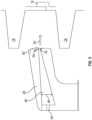
FIG. 5 is a cross-sectional view of an embodiment of an airflow nozzle of the cooling device; and -
FIG. 6 is a schematic illustration of a method of assembling a rotor assembly. - A detailed description of one or more embodiments of the disclosed device and method are presented herein by way of exemplification and not limitation with reference to the Figures.
-
FIG. 1 schematically illustrates arotor assembly 10 on arotor assembly fixture 12. Therotor assembly 10 includes a plurality ofrotor stages 14 stacked along astacking axis 16. In some embodiments,adjacent rotor stages 14 are assembled via a radialmating snap connection 18, as shown inFIG. 2 , between theadjacent rotor stages 14. Referring again toFIG. 1 , therotor assembly fixture 12 includes afixture plate 20 in which therotor stages 14 are stacked and astacking rod 22 defining thestacking axis 16 of therotor assembly 10. In some embodiments, anupper plate 24 is utilized to hold and apply pressure along thestacking axis 16 to therotor assembly 10 on therotor assembly fixture 12 during the assembly process. In order to stack therotor stages 14 and secure theadjacent rotor stages 14, it is necessary to heat themating rotor stage 14, stack therotor stage 14, apply pressure then cool themating interface 18 after the stacking. This process is repeated until thewhole rotor assembly 10 is completed. - Referring now to
FIG. 3 , to aid in the cooling of therotor stages 14, arotor cooling device 26 is utilized. Therotor cooling device 26 includes anair nozzle 28 the extends circumferentially around therotor assembly 10. In some embodiments, theair nozzle 28 is formed from a plurality ofnozzle segments 30 joined to form a circumferentialring air nozzle 28 extending entirely circumferentially around therotor assembly 10 with a nozzle outlet 32 (shown inFIG. 5 ) to direct anairflow 34 at a selected location of therotor assembly 10. Thenozzle outlet 32 is a full circumferential ring around therotor assembly 10. In some embodiments, thenozzle segments 30 each have segment end walls at each circumferential end of thenozzle segment 30. The end walls aid in controlling theairflow 34. Shown inFIG. 4a and 4b , theair nozzle 28 is supported by a plurality ofsupport rods 36 extending from thefixture plate 20. Thesupport rods 36 are adjustable or replaceable to adjust thenozzle height 38 of theair nozzle 28 relative to thefixture plate 20 so that theairflow 34 is directed from thenozzle outlet 32 to a selected location of therotor assembly 10 to cool the selected location, for example, thesnap connection 18 location of therotor assembly 10. While in the embodiments described hereinsupport rods 36 are utilized to support theair nozzle 28, one skilled in the art will readily appreciate that theair nozzle 28 may be supported by, for example, robotic arms or structures or the like. - Referring again to
FIG. 3 , theairflow 34 is directed out of theair nozzle 28 from an air source, for example, acompressed air source 40. From thecompressed air source 40, theairflow 34 proceeds through a manifold 42, which splits theairflow 34 into a plurality of airflow streams corresponding to a number ofairflow inlets 44 into theairflow nozzle 28. - Referring now to
FIG. 5 , a cross-sectional view of an embodiment of theairflow nozzle 28 is illustrated. Theairflow nozzle 28 includes anozzle channel 46 which extends circumferentially around theairflow nozzle 28 to distribute theairflow 34 uniformly from the plurality ofairflow inlets 44, which in some embodiments is eight equally-spacedairflow inlets 44. Thenozzle channel 46 tapers radially from a relatively wideaxial channel width 48 at theairflow inlets 44 to a relatively axiallynarrow channel width 48 at thenozzle outlet 32. This tapering accelerates theairflow 34 and allows theairflow 34 to be more uniformly delivered to the selected location of therotor assembly 10. Thenozzle height 38 may be monitored via a targeting device such as alaser pointer 60 or the like located on theair nozzle 28, which is directed toward therotor assembly 10 as a visual guide on the location at which theairflow 34 is directed. Thenozzle 28 then may be axially moved via adjustment or replacement of thesupport rods 36 until thelaser pointer 60 is directed at the selected location. - Referring again to
FIG. 3 , theairflow 34 into theairflow nozzle 28 may be controlled byairflow valves 50 located alongairflow lines 52 between the manifold 42 and therespective airflow inlets 44. Theairflow valves 50 may be adjusted individually, so that airflow into each of theairflow inlets 44 is independently controlled. This allows for circumferential adjustment of theairflow 34 into theairflow nozzle 28 and out of thenozzle outlet 32. Theairflow 34 exiting thenozzle outlet 32 may be monitored by, for example, one ormore anemometers 52 located at circumferential locations around thenozzle outlet 32. This may be achieved by monitoring theairflow 34 with the one or more anemometers 54 (shown inFIG. 5 ) and adjusting theairflow 34 as needed via theairflow valves 50. - Referring to
FIG. 6 , illustrated is a schematic of a process for assembling arotor assembly 10. Atblock 100, themating rotor stage 10 is heated. Arotor stage 10 is installed onto therotor assembly 14 atstep 102. Atblock 104, therotor cooling device 26 is installed, and thenozzle outlet 32 is directed at the selected cooling location, for example, thesnap connection 18 of the installedrotor stage 14 to therotor assembly 10. Theairflow valves 50 are opened atstep 106 to directairflow 34 through thenozzle outlet 32 to the selected cooling location to cool therotor assembly 10. This process is then repeated as subsequent rotor stages 14 are installed to therotor assembly 10. - The use of the
airflow nozzle 28 extending entirely circumferentially around therotor assembly 10 allows for auniform airflow 34 to be precisely directed at a desired cooling location of therotor assembly 10, and accelerates the cooling process which will result in a reduction in time required for rotor assembly, while also ensuring that the roundness and squareness requirements of thefinal rotor assembly 14 are not affected by this cooling process. - The term "about" is intended to include the degree of error associated with measurement of the particular quantity based upon the equipment available at the time of filing the application. For example, "about" can include a range of ± 8% or 5%, or 2% of a given value.
- The terminology used herein is for the purpose of describing particular embodiments only and is not intended to be limiting of the present disclosure. As used herein, the singular forms "a", "an" and "the" are intended to include the plural forms as well, unless the context clearly indicates otherwise. It will be further understood that the terms "comprises" and/or "comprising," when used in this specification, specify the presence of stated features, integers, steps, operations, elements, and/or components, but do not preclude the presence or addition of one or more other features, integers, steps, operations, element components, and/or groups thereof.
- While the present disclosure has been described with reference to an exemplary embodiment or embodiments, it will be understood by those skilled in the art that various changes may be made and equivalents may be substituted for elements thereof without departing from the scope of the present disclosure. In addition, many modifications may be made to adapt a particular situation or material to the teachings of the present disclosure without departing from the essential scope thereof. Therefore, it is intended that the present disclosure not be limited to the particular embodiment disclosed as the best mode contemplated for carrying out this present disclosure, but that the present disclosure will include all embodiments falling within the scope of the claims.
Claims (15)
- A cooling device (26) for a rotor assembly (10) of a gas turbine engine, comprising:
an airflow nozzle (28) configured to be installed at a cooling location of the rotor assembly (10), the airflow nozzle (28) extending entirely around a circumference of the rotor assembly (10) and including:a plurality of airflow inlets (44); anda nozzle outlet (32) to direct an airflow (34) toward the cooling location; andan airflow source (40) operably connected to the plurality of airflow inlets (44). - The cooling device (26) of claim 1, further comprising one or more support rods (36) operably connected to the airflow nozzle (28) to position the airflow nozzle (28).
- The cooling device (26) of claim 2, wherein the one or more support rods (36) are adjustable to change a position of the airflow nozzle (28).
- The cooling device (26) of claim 1, 2 or 3, further comprising a manifold (42) to distribute the airflow (34) from the airflow source (40) to the plurality of airflow inlets (44).
- The cooling device (26) of any preceding claim, further comprising an airflow valve (50) operably connected to each airflow inlet (44) of the plurality of airflow inlets (44) to independently control the airflow (34) through the airflow inlet (44).
- The cooling device (26) of any preceding claim, further comprising one or more anemometers (54) to monitor the airflow (34) from the nozzle outlet (32).
- A method of assembling a rotor assembly (10) comprising two or more rotor stages (14), the method comprising:heating one or more of a first rotor stage (14) or a second rotor stage (14) of the rotor assembly (10);assembling the first rotor stage (14) to the second rotor stage (14);installing a cooling device (26) circumferentially around a selected cooling location of the rotor assembly (10), the cooling device (26) including:an airflow nozzle (28) configured to be installed at a cooling location of the rotor assembly (10), the airflow nozzle (28) extending entirely around a circumference of the rotor assembly (10) and including:a plurality of airflow inlets (44); anda nozzle outlet (32); andan airflow source (40) operably connected to the plurality ofairflow inlets (44); andurging an airflow (34) from the airflow source (40) into the airflow nozzle (28) through the plurality of airflow inlets (44) and out of the nozzle outlet (32) toward the selected cooling location.
- The method of claim 7, further comprising supporting the airflow nozzle (28) via one or more support rods (36) operably connected to the airflow nozzle (28).
- The method of claim 8, further comprising adjusting the one or more support rods (36) to change a position of the airflow nozzle (28).
- The method of claim 7, 8 or 9, further comprising distributing the airflow (34) from the airflow source (40) to the plurality of airflow inlets (44) via a manifold (42) located between the airflow source (40) and the plurality of airflow inlets (44).
- The method of any of claims 7 to 10, further comprising:independently controlling the airflow (34) through the plurality of airflow inlets (44) via an airflow valve (50) operably connected to each airflow inlet (44) of the plurality of airflow inlets (44); and/ormonitoring the airflow (34) from the nozzle outlet (32) via one or more anemometers (54).
- The cooling device (26) or method of any preceding claim, wherein the airflow nozzle (28) tapers in width between the plurality of airflow inlets (44) and the nozzle outlet (32).
- The cooling device (26) or method of any preceding claim, further comprising a targeting device (60) to aid in positioning the nozzle outlet (32) relative to the selected cooling location.
- The cooling device (26) or method of any preceding claim, wherein the airflow (34) is uniform around a circumference of the nozzle outlet (32).
- The cooling device (26) or method of any preceding claim, wherein the airflow nozzle (28) comprises a plurality of circumferential nozzle segments (30).
Applications Claiming Priority (1)
| Application Number | Priority Date | Filing Date | Title |
|---|---|---|---|
| US17/862,558 US12018577B2 (en) | 2022-07-12 | 2022-07-12 | Cooling device for rotor assembly |
Publications (1)
| Publication Number | Publication Date |
|---|---|
| EP4306774A1 true EP4306774A1 (en) | 2024-01-17 |
Family
ID=87280334
Family Applications (1)
| Application Number | Title | Priority Date | Filing Date |
|---|---|---|---|
| EP23184987.8A Pending EP4306774A1 (en) | 2022-07-12 | 2023-07-12 | Cooling device for rotor assembly |
Country Status (2)
| Country | Link |
|---|---|
| US (1) | US12018577B2 (en) |
| EP (1) | EP4306774A1 (en) |
Families Citing this family (1)
| Publication number | Priority date | Publication date | Assignee | Title |
|---|---|---|---|---|
| USD1113066S1 (en) * | 2024-03-01 | 2026-02-10 | Brady Worldwide, Inc. | Housing for an electric vehicle lockout device |
Citations (4)
| Publication number | Priority date | Publication date | Assignee | Title |
|---|---|---|---|---|
| CN206316936U (en) * | 2016-08-31 | 2017-07-11 | 江苏京生管业有限公司 | The horizontal automatic ball blast production line cooling device of steel band |
| CN208419578U (en) * | 2018-06-29 | 2019-01-22 | 亚德(上海)环保系统有限公司 | A kind of rotary kiln cooling wind distribution structure |
| US20190186265A1 (en) * | 2017-12-15 | 2019-06-20 | General Electric Company | System and method for assembling gas turbine rotor using localized inductive heating |
| CN216460893U (en) * | 2021-07-30 | 2022-05-10 | 湖南恒佳新材料科技有限公司 | A detection device and system applied to continuous extrusion |
Family Cites Families (2)
| Publication number | Priority date | Publication date | Assignee | Title |
|---|---|---|---|---|
| US6158102A (en) * | 1999-03-24 | 2000-12-12 | General Electric Co. | Apparatus and methods for aligning holes through wheels and spacers and stacking the wheels and spacers to form a turbine rotor |
| US8459943B2 (en) * | 2010-03-10 | 2013-06-11 | United Technologies Corporation | Gas turbine engine rotor sections held together by tie shaft, and with blade rim undercut |
-
2022
- 2022-07-12 US US17/862,558 patent/US12018577B2/en active Active
-
2023
- 2023-07-12 EP EP23184987.8A patent/EP4306774A1/en active Pending
Patent Citations (4)
| Publication number | Priority date | Publication date | Assignee | Title |
|---|---|---|---|---|
| CN206316936U (en) * | 2016-08-31 | 2017-07-11 | 江苏京生管业有限公司 | The horizontal automatic ball blast production line cooling device of steel band |
| US20190186265A1 (en) * | 2017-12-15 | 2019-06-20 | General Electric Company | System and method for assembling gas turbine rotor using localized inductive heating |
| CN208419578U (en) * | 2018-06-29 | 2019-01-22 | 亚德(上海)环保系统有限公司 | A kind of rotary kiln cooling wind distribution structure |
| CN216460893U (en) * | 2021-07-30 | 2022-05-10 | 湖南恒佳新材料科技有限公司 | A detection device and system applied to continuous extrusion |
Also Published As
| Publication number | Publication date |
|---|---|
| US20240018884A1 (en) | 2024-01-18 |
| US12018577B2 (en) | 2024-06-25 |
Similar Documents
| Publication | Publication Date | Title |
|---|---|---|
| US9869196B2 (en) | Gas turbine engine spring mounted manifold | |
| EP4306774A1 (en) | Cooling device for rotor assembly | |
| EP3211182A1 (en) | Active hpc clearance control | |
| JP4031733B2 (en) | gas turbine | |
| US6499993B2 (en) | External dilution air tuning for dry low NOX combustors and methods therefor | |
| EP0468782A2 (en) | Gas turbine rotor and operation thereof | |
| JPS59147802A (en) | Hermetically slealing apparatus of power blade of turbine engine | |
| JP2007170384A (en) | Turbine wheel space temperature control method | |
| US20130084162A1 (en) | Gas Turbine | |
| US11635030B2 (en) | Compressor bleed apparatus for a turbine engine | |
| EP3460334B1 (en) | Fuel injector for gas turbine engines | |
| CN111608746B (en) | Device for holding a cooling tube on a turbine housing and method for mounting the same | |
| EP2722491B1 (en) | Gas turbine casing thermal control device | |
| US20100118914A1 (en) | Externally adjustable impingement cooling manifold mount and thermocouple housing | |
| US6331110B1 (en) | External dilution air tuning for dry low NOx combustors and methods therefor | |
| US20230392521A1 (en) | T-fairing installation tooling assembly | |
| EP2722490B1 (en) | Gas turbine thermal control and related method | |
| JP4111709B2 (en) | Method and apparatus for controlling bearing load in a bearing assembly | |
| US20060115356A1 (en) | Casing arrangement | |
| US11879352B2 (en) | Tool for removing a fan disc from a module | |
| EP3712386B1 (en) | Method for assembling an annular shroud assembly of a gas turbine engine and annular shroud assembly for a gas turbine engine | |
| US10669879B2 (en) | Controlling tip clearance in a turbine | |
| US7360987B2 (en) | Stator of a high-pressure turbine of a turbomachine, and a method of assembling it | |
| US10718267B2 (en) | Turbine engine cooling with substantially uniform cooling air flow distribution | |
| CN113167127B (en) | Turbine casing cooling devices for turbomachinery |
Legal Events
| Date | Code | Title | Description |
|---|---|---|---|
| PUAI | Public reference made under article 153(3) epc to a published international application that has entered the european phase |
Free format text: ORIGINAL CODE: 0009012 |
|
| STAA | Information on the status of an ep patent application or granted ep patent |
Free format text: STATUS: THE APPLICATION HAS BEEN PUBLISHED |
|
| AK | Designated contracting states |
Kind code of ref document: A1 Designated state(s): AL AT BE BG CH CY CZ DE DK EE ES FI FR GB GR HR HU IE IS IT LI LT LU LV MC ME MK MT NL NO PL PT RO RS SE SI SK SM TR |
|
| STAA | Information on the status of an ep patent application or granted ep patent |
Free format text: STATUS: REQUEST FOR EXAMINATION WAS MADE |
|
| 17P | Request for examination filed |
Effective date: 20240717 |
|
| RBV | Designated contracting states (corrected) |
Designated state(s): AL AT BE BG CH CY CZ DE DK EE ES FI FR GB GR HR HU IE IS IT LI LT LU LV MC ME MK MT NL NO PL PT RO RS SE SI SK SM TR |
|
| GRAP | Despatch of communication of intention to grant a patent |
Free format text: ORIGINAL CODE: EPIDOSNIGR1 |
|
| STAA | Information on the status of an ep patent application or granted ep patent |
Free format text: STATUS: GRANT OF PATENT IS INTENDED |
|
| INTG | Intention to grant announced |
Effective date: 20250922 |
|
| GRAJ | Information related to disapproval of communication of intention to grant by the applicant or resumption of examination proceedings by the epo deleted |
Free format text: ORIGINAL CODE: EPIDOSDIGR1 |
|
| STAA | Information on the status of an ep patent application or granted ep patent |
Free format text: STATUS: REQUEST FOR EXAMINATION WAS MADE |
|
| GRAP | Despatch of communication of intention to grant a patent |
Free format text: ORIGINAL CODE: EPIDOSNIGR1 |
|
| STAA | Information on the status of an ep patent application or granted ep patent |
Free format text: STATUS: GRANT OF PATENT IS INTENDED |
|
| INTC | Intention to grant announced (deleted) | ||
| INTG | Intention to grant announced |
Effective date: 20260218 |