EP2722491B1 - Gas turbine casing thermal control device - Google Patents
Gas turbine casing thermal control device Download PDFInfo
- Publication number
- EP2722491B1 EP2722491B1 EP13189103.8A EP13189103A EP2722491B1 EP 2722491 B1 EP2722491 B1 EP 2722491B1 EP 13189103 A EP13189103 A EP 13189103A EP 2722491 B1 EP2722491 B1 EP 2722491B1
- Authority
- EP
- European Patent Office
- Prior art keywords
- plate
- inner casing
- casing
- holes
- gas turbine
- Prior art date
- Legal status (The legal status is an assumption and is not a legal conclusion. Google has not performed a legal analysis and makes no representation as to the accuracy of the status listed.)
- Active
Links
- 238000012546 transfer Methods 0.000 claims description 18
- 238000007789 sealing Methods 0.000 claims description 4
- 238000004891 communication Methods 0.000 claims description 2
- 238000009828 non-uniform distribution Methods 0.000 claims 5
- 239000007789 gas Substances 0.000 description 29
- 238000001816 cooling Methods 0.000 description 11
- 239000003570 air Substances 0.000 description 8
- 239000000567 combustion gas Substances 0.000 description 7
- 238000002485 combustion reaction Methods 0.000 description 7
- 239000012530 fluid Substances 0.000 description 7
- 230000008901 benefit Effects 0.000 description 5
- 238000009826 distribution Methods 0.000 description 5
- 238000010438 heat treatment Methods 0.000 description 4
- 238000009434 installation Methods 0.000 description 4
- 230000000712 assembly Effects 0.000 description 3
- 238000000429 assembly Methods 0.000 description 3
- 239000000446 fuel Substances 0.000 description 3
- ATUOYWHBWRKTHZ-UHFFFAOYSA-N Propane Chemical compound CCC ATUOYWHBWRKTHZ-UHFFFAOYSA-N 0.000 description 2
- 239000012080 ambient air Substances 0.000 description 2
- 230000008859 change Effects 0.000 description 2
- 239000000112 cooling gas Substances 0.000 description 2
- 230000001419 dependent effect Effects 0.000 description 2
- 238000013461 design Methods 0.000 description 2
- 239000003949 liquefied natural gas Substances 0.000 description 2
- VNWKTOKETHGBQD-UHFFFAOYSA-N methane Chemical compound C VNWKTOKETHGBQD-UHFFFAOYSA-N 0.000 description 2
- 125000006850 spacer group Chemical group 0.000 description 2
- 230000001052 transient effect Effects 0.000 description 2
- 230000004075 alteration Effects 0.000 description 1
- 239000000571 coke Substances 0.000 description 1
- 230000008602 contraction Effects 0.000 description 1
- 230000000694 effects Effects 0.000 description 1
- 230000005611 electricity Effects 0.000 description 1
- 238000000605 extraction Methods 0.000 description 1
- 239000001257 hydrogen Substances 0.000 description 1
- 229910052739 hydrogen Inorganic materials 0.000 description 1
- 125000004435 hydrogen atom Chemical class [H]* 0.000 description 1
- 238000007373 indentation Methods 0.000 description 1
- 238000012423 maintenance Methods 0.000 description 1
- 230000013011 mating Effects 0.000 description 1
- 238000000034 method Methods 0.000 description 1
- 238000012986 modification Methods 0.000 description 1
- 230000004048 modification Effects 0.000 description 1
- 239000003345 natural gas Substances 0.000 description 1
- 230000008569 process Effects 0.000 description 1
- 239000001294 propane Substances 0.000 description 1
- 230000004044 response Effects 0.000 description 1
- 238000006467 substitution reaction Methods 0.000 description 1
- 230000007704 transition Effects 0.000 description 1
Images


Classifications
-
- F—MECHANICAL ENGINEERING; LIGHTING; HEATING; WEAPONS; BLASTING
- F01—MACHINES OR ENGINES IN GENERAL; ENGINE PLANTS IN GENERAL; STEAM ENGINES
- F01D—NON-POSITIVE DISPLACEMENT MACHINES OR ENGINES, e.g. STEAM TURBINES
- F01D11/00—Preventing or minimising internal leakage of working-fluid, e.g. between stages
- F01D11/08—Preventing or minimising internal leakage of working-fluid, e.g. between stages for sealing space between rotor blade tips and stator
- F01D11/14—Adjusting or regulating tip-clearance, i.e. distance between rotor-blade tips and stator casing
- F01D11/20—Actively adjusting tip-clearance
- F01D11/24—Actively adjusting tip-clearance by selectively cooling-heating stator or rotor components
-
- F—MECHANICAL ENGINEERING; LIGHTING; HEATING; WEAPONS; BLASTING
- F01—MACHINES OR ENGINES IN GENERAL; ENGINE PLANTS IN GENERAL; STEAM ENGINES
- F01D—NON-POSITIVE DISPLACEMENT MACHINES OR ENGINES, e.g. STEAM TURBINES
- F01D11/00—Preventing or minimising internal leakage of working-fluid, e.g. between stages
- F01D11/02—Preventing or minimising internal leakage of working-fluid, e.g. between stages by non-contact sealings, e.g. of labyrinth type
- F01D11/025—Seal clearance control; Floating assembly; Adaptation means to differential thermal dilatations
-
- F—MECHANICAL ENGINEERING; LIGHTING; HEATING; WEAPONS; BLASTING
- F01—MACHINES OR ENGINES IN GENERAL; ENGINE PLANTS IN GENERAL; STEAM ENGINES
- F01D—NON-POSITIVE DISPLACEMENT MACHINES OR ENGINES, e.g. STEAM TURBINES
- F01D11/00—Preventing or minimising internal leakage of working-fluid, e.g. between stages
- F01D11/08—Preventing or minimising internal leakage of working-fluid, e.g. between stages for sealing space between rotor blade tips and stator
- F01D11/14—Adjusting or regulating tip-clearance, i.e. distance between rotor-blade tips and stator casing
- F01D11/16—Adjusting or regulating tip-clearance, i.e. distance between rotor-blade tips and stator casing by self-adjusting means
- F01D11/18—Adjusting or regulating tip-clearance, i.e. distance between rotor-blade tips and stator casing by self-adjusting means using stator or rotor components with predetermined thermal response, e.g. selective insulation, thermal inertia, differential expansion
-
- F—MECHANICAL ENGINEERING; LIGHTING; HEATING; WEAPONS; BLASTING
- F01—MACHINES OR ENGINES IN GENERAL; ENGINE PLANTS IN GENERAL; STEAM ENGINES
- F01D—NON-POSITIVE DISPLACEMENT MACHINES OR ENGINES, e.g. STEAM TURBINES
- F01D11/00—Preventing or minimising internal leakage of working-fluid, e.g. between stages
- F01D11/08—Preventing or minimising internal leakage of working-fluid, e.g. between stages for sealing space between rotor blade tips and stator
- F01D11/14—Adjusting or regulating tip-clearance, i.e. distance between rotor-blade tips and stator casing
- F01D11/20—Actively adjusting tip-clearance
Definitions
- the subject matter disclosed herein relates to thermal control of gas turbine casings and, more particularly, to thermal control sleeve devices for preferentially heating or cooling gas turbine inner casings.
- a desired radial clearance between the tips of the rotating blades of the turbine (sometimes called "buckets") and the facing interior surfaces of the casing is important to performance of the turbine and endurance of the parts.
- the radial clearance can vary, for example, during transient operation such as start up or stoppage when rotational speed is changing. Also, temperature differences can have an effect on the clearance, not only during such transient operation as individual components are experiencing temperature change, but also during steady state operation as substantial heat is transferred to the turbine section casing internally by hot gas flowing from the combustor section.
- Casings are commonly constructed from multiple, somewhat non-uniform, arcuate portions arranged circumferentially around the turbine section and attached together, for example, at flanged edges. Accordingly, the circumferentially non-uniform configuration leads to an uneven thermal response around the casing, and non-roundness and local stress concentration can occur as the temperature of the casing changes.
- a Shroud cooling segment and assembly comprises a cooling shroud segment for a high pressure turbine that provides improved cooling in the region of the side panels from the midsection thereof forward to the leading edge and particularly in the midsection of the side panel.
- the tip clearance may be smaller than desired, or the tips may even undesirably contact the inner casing or a shroud element on the inner casing.
- U.S. Patent No. 7,690,885 discloses a gas turbine with such compressor gas extraction. Extracted cooling gas passes through plenums and baffles attached to a shroud support, arranged radially outward of a shroud that surrounds the rotating blades or the turbine, to cool the shroud's outer surface. The gas then follows different paths through the shroud to form a film cooling layer along the shroud's inner surface.
- further improvements in thermal management of turbine casings could still be made.
- a device for directing gas impingement to an inner casing of a gas turbine, according to claim 1 is disclosed..
- a gas turbine casing assembly according to claim 8 is disclosed.
- FIG. 1 schematically illustrates an embodiment of a gas turbine 110.
- the gas turbine includes an inlet section 111, a compressor section 112, a combustion section 114, a turbine section 116, and an exhaust section 117.
- a shaft 122 may be common to compressor section 112 and turbine section 116 and may be further connected to a generator 105 for generating electricity.
- the compressor section 112 may include an axial flow compressor in which a working fluid 100, such as ambient air, enters the compressor from the inlet section 111 and passes through alternating stages 113 of stationary vanes and rotating blades (shown schematically in Fig. 1 ).
- Compressor casing 118 contains working fluid 100 as the stationary vanes and rotating blades accelerate and redirect the working fluid to produce a continuous flow of compressed working fluid. The majority of the compressed working fluid flows downstream through the combustion section 114 and then the turbine section 116.
- the combustion section 114 may include any type of combustor known in the art.
- a combustor casing 115 may circumferentially surround some or all of the combustion section 114 to direct the compressed working fluid 100 from the compressor section 112 to a combustion chamber 119.
- Fuel 101 is also supplied to the combustion chamber 119.
- Possible fuels include, for example, one or more of blast furnace gas, coke oven gas, natural gas, vaporized liquefied natural gas (LNG), hydrogen, and propane.
- the compressed working fluid 100 mixes with fuel 101 in the combustion chamber 119 where it ignites to generate combustion gases having a high temperature and pressure. The combustion gases then enter the turbine section 116.
- sets of rotating blades (buckets) 124 are attached to shaft (rotor) 122, and sets of stationary blades (vanes) 126 are attached to the turbine section casing 120.
- the combustion gases pass over the first stage of rotating blades 124, the combustion gases expand, causing the rotating blades 124 and shaft 122 to rotate.
- the combustion gases then flow to the next stage of stationary blades 126 which redirect the combustion gases to the next stage of rotating buckets 124, and the process repeats for the following stages until the combustion gases exit turbine section 116 via exhaust section 117.
- Gas turbine 110 as schematically illustrated is a single shaft, single cycle turbine. However, it should be understood that such illustration is for convenience only; the present disclosure can be employed with two shaft turbines, combined cycle turbines, etc. Therefore, no limitation of the invention is intended by the turbine illustrated schematically in FIG. 1 and described above.
- turbine casing 120 comprises an inner casing 121 and an outer casing 123 defining a space 125 therebetween in communication with compressor 112 via at least one passageway 127.
- At least one circumferential shroud 128 may be affixed to the interior surface of the inner casing 121 opposing tips 132 of a set of buckets 124.
- Shrouds 128 may be positioned proximate tips 132 of rotating turbine blades 124 to minimize air leakage past the blade tips.
- the distance between each blade tip 132 and the corresponding shroud 128 is referred to as the clearance 134. It is noted that clearances 134 of each turbine stage may not be consistent, in part due to the different thermal growth characteristics of blades 124 and casing 120 during operation of the gas turbine 110.
- a contributor to the efficiency of gas turbines is the amount of air/exhaust gas leakage through the blade tip to casing shroud clearance 134. Due to the different thermal growth characteristics of turbine blades 124 and turbine casing 120, and forces created by rotation of the blades, clearances 134 can significantly change as the turbine transitions through transients from ignition to a base-load steady state condition.
- thermal control sleeves 130 are used to selectively heat or cool turbine inner casing 121 and thereby assist in the maintenance of a desired clearance 134 between respective turbine shrouds 128 and opposing blade tips 132.
- the thermal control sleeves 130 each comprises a plate 140 configured for attachment to inner casing 121 via one or more mount assemblies 142. Plates 140 have a preferentially distributed array of holes 144 extending therethrough from an inner surface 146 oriented radially inward toward shaft 122 opposing inner casing 121 and an outer surface 148 oriented radially outward away from the inner casing toward space 125 and outer casing 123.
- Holes 144 are arranged in plate 140 in a generally non-uniform manner (for example, in terms of size and/or distribution) that allows greater convective heat transfer from casing 120 in certain areas than in others.
- the areas of casing 120 that are subject to greater heat transfer could be areas that experience a higher temperature than experienced by other areas during operation, areas that have a higher mass, areas that have a lower heat transfer coefficient, etc.
- holes 144 in a predetermined fashion according to expected, calculated or empirically measured temperature distributions or transfer rates on casing 120 (with or without thermal control sleeves or any other heat management device present), one can achieve a differential thermal control of portions of inner casing 121 that are at different temperatures. In doing so, the temperature distribution across inner casing 121 in and around the areas where thermal control sleeves are mounted can be maintained in a more uniform state during operation, thereby avoiding or minimizing issues noted above when such temperatures are not maintained as uniformly as desired.
- thermal control sleeves 130 could be affixed about the circumference of the turbine inner casing 121, for example in eight groups of four.
- various other numbers and arrangements of sleeves 130 are possible. Further, the number and arrangement would vary depending on the particular size and configuration of the casing 120. Also, it should be noted that the number and arrangement of plates 140 on inner casing 121 be dependent on the configuration of the inner casing, and that the plates need not be identical.
- edges 150 of plates 140 may be partially or entirely sealed at an interface 156 with inner casing 121 so that air flow from the area 152 between the plates and the casing can only escape via holes 154 into the turbine interior, rather than by flowing around edges 150 of the plates.
- a sealing interface 156 may extend partially or entirely around plates 140.
- Such sealing interface 156 may have various forms, such as an interlocking flange 157 within a slot 159 in turbine inner casing, with or without a separate seal member, etc.
- Use of a sealing interface 156 can assist in controlling the thermal management of inner casing 121 so that it occurs substantially or completely via flow through holes 144 and 154 and/or occurs substantially via impingement.
- Holes 144 may be positioned in an array.
- the holes 144 may be spaced from each other in the range from about 0.1 to 2.0 inches, and individual holes 144 may be sized between about 0.025 and .250 inches.
- holes 144 in each plate 140 are distributed in a first grouping 158 with a first hole arrangement spaced from a second grouping 160 with a second hole arrangement.
- Central area 162 of plate 140 has relatively fewer holes 144 (in this case none).
- the first and second hole arrangements may be identical, similar or different in terms of hole size and spacing.
- the varying hole sizes and spacing compensate for the non-uniformity of the geometry of the turbine inner casing 121 area beneath plate 140 and the nonuniformity of temperature and/or heat transfer from the turbine casing area.
- the size and positioning of the holes 144 (or lack thereof) on the plate 140 produces a preferential heat transfer coefficient across inner casing 121. Accordingly, in the example shown, more heat transfer would occur from the portions of inner casing 121 near groupings 158 and 160 than beneath central area 162.
- the arrangements, sizes, spacing, density, etc. of holes 144 should not be limited by the disclosure above, and can be fine-tuned in various ways in view of the operation parameters and geometrical configuration of a particular turbine 116 and its casing 120.
- gap 164 between each plate 140 and inner casing 121 affects the heat transfer coefficient.
- gap 164 is such that heat transfer occurs substantially via impingement cooling (perpendicular flow onto the surface of inner casing 121, rather than ducting across the surface). Too large of a gap can result in an undesirably low heat transfer coefficient where the heat transfer is substantially via ducting. Too little of a gap can result in both an undesirable and a non-uniform heat transfer coefficient.
- a gap 164 of between about 0.1 and 2.0 inches provides a suitable heat transfer coefficient.
- gap 164 is not limited to this range and may be any distance that provides a suitable heat transfer coefficient.
- Gap 164 need not be uniform across the entire plate 140 or from plate to plate. Gap 164 can accordingly vary to match the casing shape, mass, temperature distribution, etc., as desired.
- impingement cooling can be achieved through substantially perpendicular flow through holes 144 in plates 140 onto the outer surface of inner casing 121. (See flow path 190 from space 125 through plate 140 into space 152, and through inner casing 121 into (and eventually out of) blades 126).
- holes 144 By placement of holes 144 in desired locations and densities, with desired dimensions, a preferentially located heating or cooling of inner casing 121 can be achieved.
- inner casing 121 can have heat transferred to or from it in a non-uniform fashion, as dictated by the plate and hole designs.
- This arrangement can vary in different turbines, in different plates within the same turbine, in different installation locations of the same turbine, or in other ways.
- the hole arrangement can be made to accommodate a variety of desired heat transfer coefficients on the outer surface of the casing, in view of particular applications and functions in a given turbine.
- the design and the use of plates 140 are therefore flexible, providing benefits in many applications.
- plates 140 can be considered thermal control devices, operating at least substantially according to impingement rather than ducting, to heat or cool impinged areas of inner casing 121.
- mount assemblies 142 can be used to provide an adjustment of the gap distance between plate 140 and turbine inner casing 121.
- mounts 142 function to hold or support the plates 140 (in particular, the holes 144) at a predetermined gap distance 164 from the surface of the turbine inner casing 121.
- Mounts 142 also allow plates 140 to float at or near a desired height over the sections of inner casing 121 as the casing diameter changes during operation of the turbine.
- Mount assemblies 142 may also or alternatively include a floating feature so that thermal and rotational expansion and contraction of turbine inner casing 121 can be accounted for during operation.
- a spring loaded, slidable or other adjustable feature may be provided allowing plates 140 and inner casing 121 to float relative to one another so that the gap may vary automatically, for example, if the diameter of inner casing 121 grows during operation of turbine 116.
- Mount 142 may comprise an assembly of various components that include a threaded bore 166 in inner casing 121, a helicoil 168 in the bore, and a threaded member such as a screw 170 in the helicoil.
- a busing 172 is located around helicoil 168, and held in place by a pin 174.
- Bushing 172 fits within a circular flange 176 in plate 140 alignable with bore 166.
- Belleville springs 178 are held between two washers 180. This arrangement beneficially allows for some float between plate 140 and inner casing 121 during use of the turbine. However, other mounting structures could be used or substituted.
- Mount assembly 142 therefore provides for improved plate 140 to inner casing 121 gap distance control and reduces the installation time when the plates are mounted to the casing, both during the initial fit-up and during subsequent re-installations. Relatively improved and tighter tolerances during the re-installations may also be maintained by the mounts 142.
- Spacers 182 may be provided on plate bottom surfaces 146 to assist in maintaining the desired gap 164. Spacers may contact indentations 184 on inner casing if desired, to ensure proper location.
Description
- The subject matter disclosed herein relates to thermal control of gas turbine casings and, more particularly, to thermal control sleeve devices for preferentially heating or cooling gas turbine inner casings.
- In gas turbines, maintaining a desired radial clearance between the tips of the rotating blades of the turbine (sometimes called "buckets") and the facing interior surfaces of the casing is important to performance of the turbine and endurance of the parts. The radial clearance can vary, for example, during transient operation such as start up or stoppage when rotational speed is changing. Also, temperature differences can have an effect on the clearance, not only during such transient operation as individual components are experiencing temperature change, but also during steady state operation as substantial heat is transferred to the turbine section casing internally by hot gas flowing from the combustor section. Casings are commonly constructed from multiple, somewhat non-uniform, arcuate portions arranged circumferentially around the turbine section and attached together, for example, at flanged edges. Accordingly, the circumferentially non-uniform configuration leads to an uneven thermal response around the casing, and non-roundness and local stress concentration can occur as the temperature of the casing changes.
- Various strategies have been used be used to control the tip/casing clearance. For example, in some gas turbines, air impingement cooling is used on the outside of the turbine casing to remove heat from the casing, thereby maintaining a more uniform temperature distribution. In such systems an external blower supplies ambient air to manifolds distributed around the casing. Use of such systems incurs capital and operational costs, and also impacts net turbine efficiency.
- Achieving a relatively uniform and suitably high heat transfer coefficient across the large, non-uniform, non-standard casing surfaces can be a challenge using such external air impingement. Accordingly, adjustable mounts have been proposed for fine tuning the distance between the casing outer surface and the opposing manifold plate.
U.S. Patent No. 8,123,406 discloses such an adjustable manifold system. - Another exemplary strategy is shown in
EP 1 176 285 Al. A Shroud cooling segment and assembly comprises a cooling shroud segment for a high pressure turbine that provides improved cooling in the region of the side panels from the midsection thereof forward to the leading edge and particularly in the midsection of the side panel. - To achieve high heat transfer rates, some gas turbines use manifold plates facing the casing with many small air outlet holes and short nozzle to surface distances. Use of such relatively small impingement cooling holes correspondingly dictates a relatively high differential pressure drop across the holes, thereby requiring cooling air supplied at a higher pressure. Consequently, a higher pressure blower may be needed adding further capital and operational cost, and further negative impact on gas turbine net efficiency. Also, external blowers of the types above can only provide air to the casing at or near room temperature, whereas heating (rather than cooling) of the casing might be desired during some operation conditions. For example, during start up as the mass of the casing is cool and the buckets begin rotating in the hot combustor flow, the tip clearance may be smaller than desired, or the tips may even undesirably contact the inner casing or a shroud element on the inner casing.
- In some systems, gas is extracted from the compressor section to cool portions of the turbine section.
U.S. Patent No. 7,690,885 discloses a gas turbine with such compressor gas extraction. Extracted cooling gas passes through plenums and baffles attached to a shroud support, arranged radially outward of a shroud that surrounds the rotating blades or the turbine, to cool the shroud's outer surface. The gas then follows different paths through the shroud to form a film cooling layer along the shroud's inner surface. However, further improvements in thermal management of turbine casings could still be made. - Aspects and advantages of the invention will be set forth in part in the following description, or may be obvious from the description, or may be learned through practice of the invention.
- According to a first aspect of the invention, a device for directing gas impingement to an inner casing of a gas turbine, according to claim 1 is disclosed..
- Various options and modifications are described in the dependent claims.
- According to another aspect of the invention, a gas turbine casing assembly, according to claim 8 is disclosed.
- These and other features, aspects and advantages of the present invention will become better understood with reference to the following description and appended claims. The accompanying drawings, which are incorporated in and constitute a part of this specification, illustrate embodiments of the invention and, together with the description, serve to explain the principles of the invention.
- The subject matter which is regarded as the invention is particularly pointed out and distinctly claimed in the claims at the conclusion of the specification. The foregoing and other features and advantages of the invention are apparent from the following detailed description taken in conjunction with the accompanying drawings in which:
-
FIG. 1 is a cross-sectional schematic view of a gas turbine; -
FIG. 2 is a cross-sectional schematic view of a portion of the gas turbine ofFIG. 1 ; -
FIG. 3 is a perspective view of an outer portion of the inner casing of the gas turbine ofFIG. 1 showing a plurality of thermal control sleeves attached to the inner casing, according to the present invention; -
FIG. 4 is a perspective view of the gas turbine inner casing as inFIG. 3 with the thermal control sleeves removed; -
FIG. 5 is a cross-sectional schematic view of the portion of the gas turbine shown in -
FIG. 3 showing the thermal control sleeves attached to the inner casing; -
FIG. 6 is a cross-sectional view of a portion of the attachment between the thermal control sleeve and the inner casing; -
FIG. 7 is a perspective view of a mount assembly for a thermal control sleeve; -
FIG. 8 is a cross-section of a lip of a thermal control sleeve mating with a groove in the inner casing; and -
FIG. 9 is a bottom view of a thermal control sleeve. - The detailed description explains embodiments of the invention, together with advantages and features, by way of example with reference to the drawings.
-
FIG. 1 schematically illustrates an embodiment of agas turbine 110. The gas turbine includes aninlet section 111, acompressor section 112, acombustion section 114, aturbine section 116, and anexhaust section 117. Ashaft 122 may be common tocompressor section 112 andturbine section 116 and may be further connected to agenerator 105 for generating electricity. - The
compressor section 112 may include an axial flow compressor in which a workingfluid 100, such as ambient air, enters the compressor from theinlet section 111 and passes throughalternating stages 113 of stationary vanes and rotating blades (shown schematically inFig. 1 ).Compressor casing 118 contains workingfluid 100 as the stationary vanes and rotating blades accelerate and redirect the working fluid to produce a continuous flow of compressed working fluid. The majority of the compressed working fluid flows downstream through thecombustion section 114 and then theturbine section 116. - The
combustion section 114 may include any type of combustor known in the art. Acombustor casing 115 may circumferentially surround some or all of thecombustion section 114 to direct the compressed workingfluid 100 from thecompressor section 112 to acombustion chamber 119.Fuel 101 is also supplied to thecombustion chamber 119. Possible fuels include, for example, one or more of blast furnace gas, coke oven gas, natural gas, vaporized liquefied natural gas (LNG), hydrogen, and propane. The compressed workingfluid 100 mixes withfuel 101 in thecombustion chamber 119 where it ignites to generate combustion gases having a high temperature and pressure. The combustion gases then enter theturbine section 116. - In
turbine section 116, sets of rotating blades (buckets) 124 are attached to shaft (rotor) 122, and sets of stationary blades (vanes) 126 are attached to theturbine section casing 120. As the combustion gases pass over the first stage of rotatingblades 124, the combustion gases expand, causing the rotatingblades 124 andshaft 122 to rotate. The combustion gases then flow to the next stage ofstationary blades 126 which redirect the combustion gases to the next stage of rotatingbuckets 124, and the process repeats for the following stages until the combustion gasesexit turbine section 116 viaexhaust section 117. -
Gas turbine 110 as schematically illustrated is a single shaft, single cycle turbine. However, it should be understood that such illustration is for convenience only; the present disclosure can be employed with two shaft turbines, combined cycle turbines, etc. Therefore, no limitation of the invention is intended by the turbine illustrated schematically inFIG. 1 and described above. - Referring to
FIGS. 1 and 2 ,turbine casing 120 comprises aninner casing 121 and anouter casing 123 defining aspace 125 therebetween in communication withcompressor 112 via at least onepassageway 127. At least onecircumferential shroud 128 may be affixed to the interior surface of theinner casing 121 opposingtips 132 of a set ofbuckets 124.Shrouds 128 may be positionedproximate tips 132 of rotatingturbine blades 124 to minimize air leakage past the blade tips. The distance between eachblade tip 132 and thecorresponding shroud 128 is referred to as theclearance 134. It is noted thatclearances 134 of each turbine stage may not be consistent, in part due to the different thermal growth characteristics ofblades 124 andcasing 120 during operation of thegas turbine 110. - A contributor to the efficiency of gas turbines is the amount of air/exhaust gas leakage through the blade tip to
casing shroud clearance 134. Due to the different thermal growth characteristics ofturbine blades 124 andturbine casing 120, and forces created by rotation of the blades,clearances 134 can significantly change as the turbine transitions through transients from ignition to a base-load steady state condition. - As illustrated in
FIG. 3 , one or morethermal control sleeves 130 are used to selectively heat or cool turbineinner casing 121 and thereby assist in the maintenance of a desiredclearance 134 betweenrespective turbine shrouds 128 and opposingblade tips 132. Thethermal control sleeves 130 each comprises aplate 140 configured for attachment toinner casing 121 via one ormore mount assemblies 142.Plates 140 have a preferentially distributed array ofholes 144 extending therethrough from aninner surface 146 oriented radially inward towardshaft 122 opposinginner casing 121 and anouter surface 148 oriented radially outward away from the inner casing towardspace 125 andouter casing 123.Holes 144 are arranged inplate 140 in a generally non-uniform manner (for example, in terms of size and/or distribution) that allows greater convective heat transfer from casing 120 in certain areas than in others. If desired, the areas ofcasing 120 that are subject to greater heat transfer could be areas that experience a higher temperature than experienced by other areas during operation, areas that have a higher mass, areas that have a lower heat transfer coefficient, etc. Accordingly, by arrangingholes 144 in a predetermined fashion according to expected, calculated or empirically measured temperature distributions or transfer rates on casing 120 (with or without thermal control sleeves or any other heat management device present), one can achieve a differential thermal control of portions ofinner casing 121 that are at different temperatures. In doing so, the temperature distribution acrossinner casing 121 in and around the areas where thermal control sleeves are mounted can be maintained in a more uniform state during operation, thereby avoiding or minimizing issues noted above when such temperatures are not maintained as uniformly as desired. - In the embodiment of
FIG. 3 , a plurality (e.g., 32) ofthermal control sleeves 130 could be affixed about the circumference of the turbineinner casing 121, for example in eight groups of four. However, various other numbers and arrangements ofsleeves 130 are possible. Further, the number and arrangement would vary depending on the particular size and configuration of thecasing 120. Also, it should be noted that the number and arrangement ofplates 140 oninner casing 121 be dependent on the configuration of the inner casing, and that the plates need not be identical. - If desired, edges 150 of
plates 140 may be partially or entirely sealed at aninterface 156 withinner casing 121 so that air flow from thearea 152 between the plates and the casing can only escape viaholes 154 into the turbine interior, rather than by flowing around edges 150 of the plates. In such case, a sealinginterface 156 may extend partially or entirely aroundplates 140.Such sealing interface 156 may have various forms, such as an interlockingflange 157 within aslot 159 in turbine inner casing, with or without a separate seal member, etc. Use of a sealinginterface 156 can assist in controlling the thermal management ofinner casing 121 so that it occurs substantially or completely via flow throughholes -
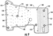
Holes 144 may be positioned in an array. In an exemplary embodiment, theholes 144 may be spaced from each other in the range from about 0.1 to 2.0 inches, andindividual holes 144 may be sized between about 0.025 and .250 inches. Thus a variety of hole sizes and densities is possible between plates or within a given plates. As shown inFIG. 3 , holes 144 in eachplate 140 are distributed in afirst grouping 158 with a first hole arrangement spaced from asecond grouping 160 with a second hole arrangement.Central area 162 ofplate 140 has relatively fewer holes 144 (in this case none). The first and second hole arrangements may be identical, similar or different in terms of hole size and spacing. The varying hole sizes and spacing compensate for the non-uniformity of the geometry of the turbineinner casing 121 area beneathplate 140 and the nonuniformity of temperature and/or heat transfer from the turbine casing area. The size and positioning of the holes 144 (or lack thereof) on theplate 140 produces a preferential heat transfer coefficient acrossinner casing 121. Accordingly, in the example shown, more heat transfer would occur from the portions ofinner casing 121near groupings central area 162. However, it should be understood that the arrangements, sizes, spacing, density, etc. ofholes 144 should not be limited by the disclosure above, and can be fine-tuned in various ways in view of the operation parameters and geometrical configuration of aparticular turbine 116 and itscasing 120. - The
gap 164 between eachplate 140 andinner casing 121 affects the heat transfer coefficient. In one embodiment,gap 164 is such that heat transfer occurs substantially via impingement cooling (perpendicular flow onto the surface ofinner casing 121, rather than ducting across the surface). Too large of a gap can result in an undesirably low heat transfer coefficient where the heat transfer is substantially via ducting. Too little of a gap can result in both an undesirable and a non-uniform heat transfer coefficient. In an exemplary embodiment, agap 164 of between about 0.1 and 2.0 inches provides a suitable heat transfer coefficient. However,gap 164 is not limited to this range and may be any distance that provides a suitable heat transfer coefficient. Also, it should be understood thatgap 164 need not be uniform across theentire plate 140 or from plate to plate.Gap 164 can accordingly vary to match the casing shape, mass, temperature distribution, etc., as desired. - By maintaining
gap 164 in the desired range, with the pressures experienced by a gas turbines and using gas extracted fromcompressor 112, impingement cooling can be achieved through substantially perpendicular flow throughholes 144 inplates 140 onto the outer surface ofinner casing 121. (Seeflow path 190 fromspace 125 throughplate 140 intospace 152, and throughinner casing 121 into (and eventually out of) blades 126). By placement ofholes 144 in desired locations and densities, with desired dimensions, a preferentially located heating or cooling ofinner casing 121 can be achieved. In other words,inner casing 121 can have heat transferred to or from it in a non-uniform fashion, as dictated by the plate and hole designs. This arrangement can vary in different turbines, in different plates within the same turbine, in different installation locations of the same turbine, or in other ways. Thus, the hole arrangement can be made to accommodate a variety of desired heat transfer coefficients on the outer surface of the casing, in view of particular applications and functions in a given turbine. The design and the use ofplates 140 are therefore flexible, providing benefits in many applications. - During start-up the extracted compressor gases will actually be warmer than
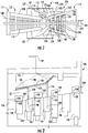
inner casing 121. Therefore, during wind up until a steady state is achieved, the preferential thermal control achieved would be substantially the heating of the impinged areas ofcasing 121 opposingholes 144. At some point during wind-up and/or once steady state is achieved the extracted compressor gas will function to cool the impinged area. Accordingly,plates 140 can be considered thermal control devices, operating at least substantially according to impingement rather than ducting, to heat or cool impinged areas ofinner casing 121. - Referring to
FIG. 7 ,mount assemblies 142 can be used to provide an adjustment of the gap distance betweenplate 140 and turbineinner casing 121. As shown, mounts 142 function to hold or support the plates 140 (in particular, the holes 144) at apredetermined gap distance 164 from the surface of the turbineinner casing 121.Mounts 142 also allowplates 140 to float at or near a desired height over the sections ofinner casing 121 as the casing diameter changes during operation of the turbine.Mount assemblies 142 may also or alternatively include a floating feature so that thermal and rotational expansion and contraction of turbineinner casing 121 can be accounted for during operation. That is, a spring loaded, slidable or other adjustable feature may be provided allowingplates 140 andinner casing 121 to float relative to one another so that the gap may vary automatically, for example, if the diameter ofinner casing 121 grows during operation ofturbine 116. -
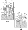
Mount 142 may comprise an assembly of various components that include a threadedbore 166 ininner casing 121, ahelicoil 168 in the bore, and a threaded member such as ascrew 170 in the helicoil. Abusing 172 is located aroundhelicoil 168, and held in place by apin 174. Bushing 172 fits within acircular flange 176 inplate 140 alignable withbore 166. Belleville springs 178 are held between twowashers 180. This arrangement beneficially allows for some float betweenplate 140 andinner casing 121 during use of the turbine. However, other mounting structures could be used or substituted. -
Mount assembly 142 therefore provides forimproved plate 140 toinner casing 121 gap distance control and reduces the installation time when the plates are mounted to the casing, both during the initial fit-up and during subsequent re-installations. Relatively improved and tighter tolerances during the re-installations may also be maintained by themounts 142.Spacers 182 may be provided on plate bottom surfaces 146 to assist in maintaining the desiredgap 164. Spacers may contactindentations 184 on inner casing if desired, to ensure proper location. - While the invention has been described in detail in connection with only a limited number of embodiments, it should be readily understood that the invention is not limited to such disclosed embodiments. Rather, the invention can be modified to incorporate any number of variations, alterations, substitutions or equivalent arrangements not heretofore described, but which are commensurate with the scope of the invention. Additionally, while various embodiments of the invention have been described, it is to be understood that aspects of the invention may include only some of the described embodiments. Accordingly, the invention is not to be seen as limited by the foregoing description, but is only limited by the scope of the appended claims.
Claims (9)
- A device for directing gas impingement to an inner casing (121) of a gas turbine (110) to cool or heat the inner casing, the device comprising:a thermal control sleeve (130) comprising a plate (140) configured for attachment to the outer surface of the inner casing, the plate having a first surface (146) opposing the inner casing when the plate is attached to an area of the inner casing and having a second surface (148) opposite the first surface, the plate defining a plurality of holes (144) through the plate from the first surface to the second surface, the holes arranged with a predetermined non-uniform distribution in the plate corresponding to a desired preferential impingement pattern for providing non-uniform heat transfer from the area during operation of the gas turbine so as to control temperature of the inner casing across the area,.the device further including at least one mounting assembly (142) for attaching the plate (140) to the inner casing (121), wherein the mounting assembly (142) is configured to attach the plate (140) to the inner casing (121) so that the plate can float relative to the inner casing area during operation of the gas turbine (110) to account for changes in size of the inner casing during operation, in particular by means of a mount which allow the plates (140) to float at or near a desired height over sections of inner casing (121).
- The device of claim 1, wherein the plate includes a flange (157) around a perimeter of the plate for sealing attachment of the plate to the area of the inner casing (121).
- The device of any of the preceding claims, wherein the predetermined non-uniform distribution includes providing holes of differing sizes in different portions of the plate (140).
- The device of any of the preceding claims, wherein the predetermined non-uniform distribution includes arranging holes with differing densities in different portions of the plate (140).
- The device of claim 6, wherein a first portion of the plate (140) includes holes arranged with a first density and a second portion of the plate includes holes arranged with a second density different from the first density.
- The device of any of the preceding claims, wherein the plate (140) has two ends and a middle portion (162) between the ends, the predetermined non-uniform distribution including providing a higher density of holes proximate at least one of the ends than in the middle portion.
- The device of any of the preceding claims, wherein the plate has two ends and a middle portion (162) between the ends, the predetermined non-uniform distribution including providing a larger holes proximate at least one of the ends than in the middle portion.
- A gas turbine (110) casing assembly comprising:the device of any of the preceding claimsan inner casing (121) arranged around a central axis, the inner casing (121) defining an opening therethrough in communication with an interior of the gas turbine;an outer casing (123) arranged around the inner casing (121); andthe at least one plate (140) attached to an outer surface of the inner casing (121), the plate (140) and inner casing (121) defining a thermal control gas flow path from radially outside of the plate through the holes (144) in the plate and then through the inner casing (121) into the interior of the gas turbine.
- The gas turbine (110) casing assembly of claim 8, wherein the plate (140) and inner casing (121) are attached via a flanged interface that is at least substantially airtight.
Applications Claiming Priority (1)
| Application Number | Priority Date | Filing Date | Title |
|---|---|---|---|
| US13/654,672 US9238971B2 (en) | 2012-10-18 | 2012-10-18 | Gas turbine casing thermal control device |
Publications (3)
| Publication Number | Publication Date |
|---|---|
| EP2722491A2 EP2722491A2 (en) | 2014-04-23 |
| EP2722491A3 EP2722491A3 (en) | 2017-08-09 |
| EP2722491B1 true EP2722491B1 (en) | 2021-05-26 |
Family
ID=49447390
Family Applications (1)
| Application Number | Title | Priority Date | Filing Date |
|---|---|---|---|
| EP13189103.8A Active EP2722491B1 (en) | 2012-10-18 | 2013-10-17 | Gas turbine casing thermal control device |
Country Status (4)
| Country | Link |
|---|---|
| US (1) | US9238971B2 (en) |
| EP (1) | EP2722491B1 (en) |
| JP (1) | JP6176722B2 (en) |
| CN (1) | CN203626900U (en) |
Families Citing this family (6)
| Publication number | Priority date | Publication date | Assignee | Title |
|---|---|---|---|---|
| US9422824B2 (en) * | 2012-10-18 | 2016-08-23 | General Electric Company | Gas turbine thermal control and related method |
| US9874105B2 (en) | 2015-01-26 | 2018-01-23 | United Technologies Corporation | Active clearance control systems |
| RU2605143C1 (en) * | 2015-07-17 | 2016-12-20 | Валерий Николаевич Сиротин | Aircraft bypass turbojet engine two high pressure turbines cooling system |
| US10975721B2 (en) | 2016-01-12 | 2021-04-13 | Pratt & Whitney Canada Corp. | Cooled containment case using internal plenum |
| US11035251B2 (en) * | 2019-09-26 | 2021-06-15 | General Electric Company | Stator temperature control system for a gas turbine engine |
| CN117147164B (en) * | 2023-11-01 | 2024-01-30 | 中国航发沈阳发动机研究所 | Hole detection device for double-layer casing of aero-engine |
Family Cites Families (28)
| Publication number | Priority date | Publication date | Assignee | Title |
|---|---|---|---|---|
| US3966354A (en) * | 1974-12-19 | 1976-06-29 | General Electric Company | Thermal actuated valve for clearance control |
| US4292801A (en) | 1979-07-11 | 1981-10-06 | General Electric Company | Dual stage-dual mode low nox combustor |
| FR2540560B1 (en) * | 1983-02-03 | 1987-06-12 | Snecma | DEVICE FOR SEALING MOBILE BLADES OF A TURBOMACHINE |
| FR2570763B1 (en) * | 1984-09-27 | 1986-11-28 | Snecma | DEVICE FOR AUTOMATICALLY CONTROLLING THE PLAY OF A TURBOMACHINE LABYRINTH SEAL |
| US4833878A (en) | 1987-04-09 | 1989-05-30 | Solar Turbines Incorporated | Wide range gaseous fuel combustion system for gas turbine engines |
| US5116199A (en) | 1990-12-20 | 1992-05-26 | General Electric Company | Blade tip clearance control apparatus using shroud segment annular support ring thermal expansion |
| US5281085A (en) | 1990-12-21 | 1994-01-25 | General Electric Company | Clearance control system for separately expanding or contracting individual portions of an annular shroud |
| US5603510A (en) * | 1991-06-13 | 1997-02-18 | Sanders; William P. | Variable clearance seal assembly |
| US5399066A (en) * | 1993-09-30 | 1995-03-21 | General Electric Company | Integral clearance control impingement manifold and environmental shield |
| US5509780A (en) * | 1995-03-08 | 1996-04-23 | General Electric Co. | Apparatus and method for providing uniform radial clearance of seals between rotating and stationary components |
| US5779436A (en) * | 1996-08-07 | 1998-07-14 | Solar Turbines Incorporated | Turbine blade clearance control system |
| US5819525A (en) | 1997-03-14 | 1998-10-13 | Westinghouse Electric Corporation | Cooling supply manifold assembly for cooling combustion turbine components |
| DE19756734A1 (en) | 1997-12-19 | 1999-06-24 | Bmw Rolls Royce Gmbh | Passive gap system of a gas turbine |
| US6354795B1 (en) * | 2000-07-27 | 2002-03-12 | General Electric Company | Shroud cooling segment and assembly |
| JP2005513330A (en) | 2001-12-13 | 2005-05-12 | アルストム テクノロジー リミテッド | High-temperature gas flow path structure of gas turbine |
| US7086233B2 (en) | 2003-11-26 | 2006-08-08 | Siemens Power Generation, Inc. | Blade tip clearance control |
| US8801370B2 (en) | 2006-10-12 | 2014-08-12 | General Electric Company | Turbine case impingement cooling for heavy duty gas turbines |
| US7690885B2 (en) | 2006-11-30 | 2010-04-06 | General Electric Company | Methods and system for shielding cooling air to facilitate cooling integral turbine nozzle and shroud assemblies |
| US7914254B2 (en) | 2007-02-13 | 2011-03-29 | General Electric Company | Integrated support/thermocouple housing for impingement cooling manifolds and cooling method |
| GB0703827D0 (en) * | 2007-02-28 | 2007-04-11 | Rolls Royce Plc | Rotor seal segment |
| US7811054B2 (en) | 2007-05-30 | 2010-10-12 | General Electric Company | Shroud configuration having sloped seal |
| US8021109B2 (en) | 2008-01-22 | 2011-09-20 | General Electric Company | Turbine casing with false flange |
| US8123406B2 (en) * | 2008-11-10 | 2012-02-28 | General Electric Company | Externally adjustable impingement cooling manifold mount and thermocouple housing |
| GB2469490B (en) | 2009-04-16 | 2012-03-07 | Rolls Royce Plc | Turbine casing cooling |
| US8342798B2 (en) * | 2009-07-28 | 2013-01-01 | General Electric Company | System and method for clearance control in a rotary machine |
| US8397516B2 (en) | 2009-10-01 | 2013-03-19 | General Electric Company | Apparatus and method for removing heat from a gas turbine |
| US8651809B2 (en) | 2010-10-13 | 2014-02-18 | General Electric Company | Apparatus and method for aligning a turbine casing |
| US9115595B2 (en) * | 2012-04-09 | 2015-08-25 | General Electric Company | Clearance control system for a gas turbine |
-
2012
- 2012-10-18 US US13/654,672 patent/US9238971B2/en active Active
-
2013
- 2013-10-07 JP JP2013209765A patent/JP6176722B2/en active Active
- 2013-10-17 EP EP13189103.8A patent/EP2722491B1/en active Active
- 2013-10-18 CN CN201320643542.1U patent/CN203626900U/en not_active Expired - Lifetime
Non-Patent Citations (1)
| Title |
|---|
| None * |
Also Published As
| Publication number | Publication date |
|---|---|
| US9238971B2 (en) | 2016-01-19 |
| EP2722491A2 (en) | 2014-04-23 |
| EP2722491A3 (en) | 2017-08-09 |
| CN203626900U (en) | 2014-06-04 |
| US20140112759A1 (en) | 2014-04-24 |
| JP2014084865A (en) | 2014-05-12 |
| JP6176722B2 (en) | 2017-08-09 |
Similar Documents
| Publication | Publication Date | Title |
|---|---|---|
| EP2722491B1 (en) | Gas turbine casing thermal control device | |
| EP1914392B1 (en) | Turbine case impingement cooling for heavy duty gas turbines | |
| JP5484474B2 (en) | Sealing between combustion chamber and turbine distributor in turbine engine | |
| EP1630385B1 (en) | Method and apparatus for maintaining rotor assembly tip clearances | |
| US7165937B2 (en) | Methods and apparatus for maintaining rotor assembly tip clearances | |
| US9464538B2 (en) | Shroud block segment for a gas turbine | |
| US8205457B2 (en) | Gas turbine engine combustor and method for delivering purge gas into a combustion chamber of the combustor | |
| US7914254B2 (en) | Integrated support/thermocouple housing for impingement cooling manifolds and cooling method | |
| EP2551467B1 (en) | Gas turbine engine active clearance control system and corresponding method | |
| US20130084162A1 (en) | Gas Turbine | |
| EP2722490B1 (en) | Gas turbine thermal control and related method | |
| JP2015017608A (en) | Gas turbine shroud cooling | |
| EP2473711B1 (en) | Metering plate for internally cooled nozzle guide vane doublets. | |
| EP2949871B1 (en) | Variable vane segment | |
| EP3409900A1 (en) | Clearance control arrangement and corresponding gas turbine engine | |
| EP1978213A2 (en) | Mounting system for impingement cooling manifold | |
| US20140050558A1 (en) | Temperature gradient management arrangement for a turbine system and method of managing a temperature gradient of a turbine system | |
| WO2017052794A2 (en) | Turbocooled vane of a gas turbine engine |
Legal Events
| Date | Code | Title | Description |
|---|---|---|---|
| PUAI | Public reference made under article 153(3) epc to a published international application that has entered the european phase |
Free format text: ORIGINAL CODE: 0009012 |
|
| AK | Designated contracting states |
Kind code of ref document: A2 Designated state(s): AL AT BE BG CH CY CZ DE DK EE ES FI FR GB GR HR HU IE IS IT LI LT LU LV MC MK MT NL NO PL PT RO RS SE SI SK SM TR |
|
| AX | Request for extension of the european patent |
Extension state: BA ME |
|
| PUAL | Search report despatched |
Free format text: ORIGINAL CODE: 0009013 |
|
| AK | Designated contracting states |
Kind code of ref document: A3 Designated state(s): AL AT BE BG CH CY CZ DE DK EE ES FI FR GB GR HR HU IE IS IT LI LT LU LV MC MK MT NL NO PL PT RO RS SE SI SK SM TR |
|
| AX | Request for extension of the european patent |
Extension state: BA ME |
|
| RIC1 | Information provided on ipc code assigned before grant |
Ipc: F01D 11/24 20060101AFI20170704BHEP Ipc: F01D 11/02 20060101ALI20170704BHEP Ipc: F01D 11/20 20060101ALI20170704BHEP Ipc: F01D 11/16 20060101ALI20170704BHEP Ipc: F01D 11/18 20060101ALI20170704BHEP Ipc: F01D 11/14 20060101ALI20170704BHEP |
|
| STAA | Information on the status of an ep patent application or granted ep patent |
Free format text: STATUS: REQUEST FOR EXAMINATION WAS MADE |
|
| 17P | Request for examination filed |
Effective date: 20180209 |
|
| RBV | Designated contracting states (corrected) |
Designated state(s): AL AT BE BG CH CY CZ DE DK EE ES FI FR GB GR HR HU IE IS IT LI LT LU LV MC MK MT NL NO PL PT RO RS SE SI SK SM TR |
|
| STAA | Information on the status of an ep patent application or granted ep patent |
Free format text: STATUS: EXAMINATION IS IN PROGRESS |
|
| 17Q | First examination report despatched |
Effective date: 20190627 |
|
| GRAP | Despatch of communication of intention to grant a patent |
Free format text: ORIGINAL CODE: EPIDOSNIGR1 |
|
| STAA | Information on the status of an ep patent application or granted ep patent |
Free format text: STATUS: GRANT OF PATENT IS INTENDED |
|
| INTG | Intention to grant announced |
Effective date: 20210129 |
|
| GRAS | Grant fee paid |
Free format text: ORIGINAL CODE: EPIDOSNIGR3 |
|
| GRAA | (expected) grant |
Free format text: ORIGINAL CODE: 0009210 |
|
| STAA | Information on the status of an ep patent application or granted ep patent |
Free format text: STATUS: THE PATENT HAS BEEN GRANTED |
|
| AK | Designated contracting states |
Kind code of ref document: B1 Designated state(s): AL AT BE BG CH CY CZ DE DK EE ES FI FR GB GR HR HU IE IS IT LI LT LU LV MC MK MT NL NO PL PT RO RS SE SI SK SM TR |
|
| REG | Reference to a national code |
Ref country code: GB Ref legal event code: FG4D |
|
| REG | Reference to a national code |
Ref country code: CH Ref legal event code: EP |
|
| REG | Reference to a national code |
Ref country code: AT Ref legal event code: REF Ref document number: 1396411 Country of ref document: AT Kind code of ref document: T Effective date: 20210615 |
|
| REG | Reference to a national code |
Ref country code: DE Ref legal event code: R096 Ref document number: 602013077638 Country of ref document: DE |
|
| REG | Reference to a national code |
Ref country code: IE Ref legal event code: FG4D |
|
| REG | Reference to a national code |
Ref country code: LT Ref legal event code: MG9D |
|
| REG | Reference to a national code |
Ref country code: AT Ref legal event code: MK05 Ref document number: 1396411 Country of ref document: AT Kind code of ref document: T Effective date: 20210526 |
|
| PG25 | Lapsed in a contracting state [announced via postgrant information from national office to epo] |
Ref country code: AT Free format text: LAPSE BECAUSE OF FAILURE TO SUBMIT A TRANSLATION OF THE DESCRIPTION OR TO PAY THE FEE WITHIN THE PRESCRIBED TIME-LIMIT Effective date: 20210526 Ref country code: BG Free format text: LAPSE BECAUSE OF FAILURE TO SUBMIT A TRANSLATION OF THE DESCRIPTION OR TO PAY THE FEE WITHIN THE PRESCRIBED TIME-LIMIT Effective date: 20210826 Ref country code: HR Free format text: LAPSE BECAUSE OF FAILURE TO SUBMIT A TRANSLATION OF THE DESCRIPTION OR TO PAY THE FEE WITHIN THE PRESCRIBED TIME-LIMIT Effective date: 20210526 Ref country code: LT Free format text: LAPSE BECAUSE OF FAILURE TO SUBMIT A TRANSLATION OF THE DESCRIPTION OR TO PAY THE FEE WITHIN THE PRESCRIBED TIME-LIMIT Effective date: 20210526 Ref country code: FI Free format text: LAPSE BECAUSE OF FAILURE TO SUBMIT A TRANSLATION OF THE DESCRIPTION OR TO PAY THE FEE WITHIN THE PRESCRIBED TIME-LIMIT Effective date: 20210526 |
|
| REG | Reference to a national code |
Ref country code: NL Ref legal event code: MP Effective date: 20210526 |
|
| PG25 | Lapsed in a contracting state [announced via postgrant information from national office to epo] |
Ref country code: PL Free format text: LAPSE BECAUSE OF FAILURE TO SUBMIT A TRANSLATION OF THE DESCRIPTION OR TO PAY THE FEE WITHIN THE PRESCRIBED TIME-LIMIT Effective date: 20210526 Ref country code: NO Free format text: LAPSE BECAUSE OF FAILURE TO SUBMIT A TRANSLATION OF THE DESCRIPTION OR TO PAY THE FEE WITHIN THE PRESCRIBED TIME-LIMIT Effective date: 20210826 Ref country code: PT Free format text: LAPSE BECAUSE OF FAILURE TO SUBMIT A TRANSLATION OF THE DESCRIPTION OR TO PAY THE FEE WITHIN THE PRESCRIBED TIME-LIMIT Effective date: 20210927 Ref country code: GR Free format text: LAPSE BECAUSE OF FAILURE TO SUBMIT A TRANSLATION OF THE DESCRIPTION OR TO PAY THE FEE WITHIN THE PRESCRIBED TIME-LIMIT Effective date: 20210827 Ref country code: LV Free format text: LAPSE BECAUSE OF FAILURE TO SUBMIT A TRANSLATION OF THE DESCRIPTION OR TO PAY THE FEE WITHIN THE PRESCRIBED TIME-LIMIT Effective date: 20210526 Ref country code: IS Free format text: LAPSE BECAUSE OF FAILURE TO SUBMIT A TRANSLATION OF THE DESCRIPTION OR TO PAY THE FEE WITHIN THE PRESCRIBED TIME-LIMIT Effective date: 20210926 Ref country code: SE Free format text: LAPSE BECAUSE OF FAILURE TO SUBMIT A TRANSLATION OF THE DESCRIPTION OR TO PAY THE FEE WITHIN THE PRESCRIBED TIME-LIMIT Effective date: 20210526 Ref country code: RS Free format text: LAPSE BECAUSE OF FAILURE TO SUBMIT A TRANSLATION OF THE DESCRIPTION OR TO PAY THE FEE WITHIN THE PRESCRIBED TIME-LIMIT Effective date: 20210526 |
|
| PG25 | Lapsed in a contracting state [announced via postgrant information from national office to epo] |
Ref country code: NL Free format text: LAPSE BECAUSE OF FAILURE TO SUBMIT A TRANSLATION OF THE DESCRIPTION OR TO PAY THE FEE WITHIN THE PRESCRIBED TIME-LIMIT Effective date: 20210526 |
|
| PG25 | Lapsed in a contracting state [announced via postgrant information from national office to epo] |
Ref country code: SM Free format text: LAPSE BECAUSE OF FAILURE TO SUBMIT A TRANSLATION OF THE DESCRIPTION OR TO PAY THE FEE WITHIN THE PRESCRIBED TIME-LIMIT Effective date: 20210526 Ref country code: SK Free format text: LAPSE BECAUSE OF FAILURE TO SUBMIT A TRANSLATION OF THE DESCRIPTION OR TO PAY THE FEE WITHIN THE PRESCRIBED TIME-LIMIT Effective date: 20210526 Ref country code: EE Free format text: LAPSE BECAUSE OF FAILURE TO SUBMIT A TRANSLATION OF THE DESCRIPTION OR TO PAY THE FEE WITHIN THE PRESCRIBED TIME-LIMIT Effective date: 20210526 Ref country code: CZ Free format text: LAPSE BECAUSE OF FAILURE TO SUBMIT A TRANSLATION OF THE DESCRIPTION OR TO PAY THE FEE WITHIN THE PRESCRIBED TIME-LIMIT Effective date: 20210526 Ref country code: DK Free format text: LAPSE BECAUSE OF FAILURE TO SUBMIT A TRANSLATION OF THE DESCRIPTION OR TO PAY THE FEE WITHIN THE PRESCRIBED TIME-LIMIT Effective date: 20210526 Ref country code: RO Free format text: LAPSE BECAUSE OF FAILURE TO SUBMIT A TRANSLATION OF THE DESCRIPTION OR TO PAY THE FEE WITHIN THE PRESCRIBED TIME-LIMIT Effective date: 20210526 Ref country code: ES Free format text: LAPSE BECAUSE OF FAILURE TO SUBMIT A TRANSLATION OF THE DESCRIPTION OR TO PAY THE FEE WITHIN THE PRESCRIBED TIME-LIMIT Effective date: 20210526 |
|
| REG | Reference to a national code |
Ref country code: DE Ref legal event code: R097 Ref document number: 602013077638 Country of ref document: DE |
|
| PLBE | No opposition filed within time limit |
Free format text: ORIGINAL CODE: 0009261 |
|
| STAA | Information on the status of an ep patent application or granted ep patent |
Free format text: STATUS: NO OPPOSITION FILED WITHIN TIME LIMIT |
|
| 26N | No opposition filed |
Effective date: 20220301 |
|
| REG | Reference to a national code |
Ref country code: CH Ref legal event code: PL |
|
| PG25 | Lapsed in a contracting state [announced via postgrant information from national office to epo] |
Ref country code: IS Free format text: LAPSE BECAUSE OF FAILURE TO SUBMIT A TRANSLATION OF THE DESCRIPTION OR TO PAY THE FEE WITHIN THE PRESCRIBED TIME-LIMIT Effective date: 20210926 Ref country code: AL Free format text: LAPSE BECAUSE OF FAILURE TO SUBMIT A TRANSLATION OF THE DESCRIPTION OR TO PAY THE FEE WITHIN THE PRESCRIBED TIME-LIMIT Effective date: 20210526 |
|
| REG | Reference to a national code |
Ref country code: BE Ref legal event code: MM Effective date: 20211031 |
|
| GBPC | Gb: european patent ceased through non-payment of renewal fee |
Effective date: 20211017 |
|
| PG25 | Lapsed in a contracting state [announced via postgrant information from national office to epo] |
Ref country code: MC Free format text: LAPSE BECAUSE OF FAILURE TO SUBMIT A TRANSLATION OF THE DESCRIPTION OR TO PAY THE FEE WITHIN THE PRESCRIBED TIME-LIMIT Effective date: 20210526 |
|
| PG25 | Lapsed in a contracting state [announced via postgrant information from national office to epo] |
Ref country code: LU Free format text: LAPSE BECAUSE OF NON-PAYMENT OF DUE FEES Effective date: 20211017 Ref country code: GB Free format text: LAPSE BECAUSE OF NON-PAYMENT OF DUE FEES Effective date: 20211017 Ref country code: BE Free format text: LAPSE BECAUSE OF NON-PAYMENT OF DUE FEES Effective date: 20211031 |
|
| PG25 | Lapsed in a contracting state [announced via postgrant information from national office to epo] |
Ref country code: LI Free format text: LAPSE BECAUSE OF NON-PAYMENT OF DUE FEES Effective date: 20211031 Ref country code: CH Free format text: LAPSE BECAUSE OF NON-PAYMENT OF DUE FEES Effective date: 20211031 |
|
| PG25 | Lapsed in a contracting state [announced via postgrant information from national office to epo] |
Ref country code: FR Free format text: LAPSE BECAUSE OF NON-PAYMENT OF DUE FEES Effective date: 20211031 |
|
| PG25 | Lapsed in a contracting state [announced via postgrant information from national office to epo] |
Ref country code: IE Free format text: LAPSE BECAUSE OF NON-PAYMENT OF DUE FEES Effective date: 20211017 |
|
| PG25 | Lapsed in a contracting state [announced via postgrant information from national office to epo] |
Ref country code: HU Free format text: LAPSE BECAUSE OF FAILURE TO SUBMIT A TRANSLATION OF THE DESCRIPTION OR TO PAY THE FEE WITHIN THE PRESCRIBED TIME-LIMIT; INVALID AB INITIO Effective date: 20131017 |
|
| PG25 | Lapsed in a contracting state [announced via postgrant information from national office to epo] |
Ref country code: CY Free format text: LAPSE BECAUSE OF FAILURE TO SUBMIT A TRANSLATION OF THE DESCRIPTION OR TO PAY THE FEE WITHIN THE PRESCRIBED TIME-LIMIT Effective date: 20210526 |
|
| PGFP | Annual fee paid to national office [announced via postgrant information from national office to epo] |
Ref country code: IT Payment date: 20230920 Year of fee payment: 11 |
|
| REG | Reference to a national code |
Ref country code: DE Ref legal event code: R081 Ref document number: 602013077638 Country of ref document: DE Owner name: GENERAL ELECTRIC TECHNOLOGY GMBH, CH Free format text: FORMER OWNER: GENERAL ELECTRIC COMPANY, SCHENECTADY, NY, US |
|
| PGFP | Annual fee paid to national office [announced via postgrant information from national office to epo] |
Ref country code: DE Payment date: 20230920 Year of fee payment: 11 |