EP4306422A2 - Aircraft propulsion system with intermittent combustion engine(s) - Google Patents
Aircraft propulsion system with intermittent combustion engine(s) Download PDFInfo
- Publication number
- EP4306422A2 EP4306422A2 EP23185410.0A EP23185410A EP4306422A2 EP 4306422 A2 EP4306422 A2 EP 4306422A2 EP 23185410 A EP23185410 A EP 23185410A EP 4306422 A2 EP4306422 A2 EP 4306422A2
- Authority
- EP
- European Patent Office
- Prior art keywords
- propulsor
- rotor
- transmission
- aircraft
- combustion engine
- Prior art date
- Legal status (The legal status is an assumption and is not a legal conclusion. Google has not performed a legal analysis and makes no representation as to the accuracy of the status listed.)
- Granted
Links
Images




Classifications
-
- B—PERFORMING OPERATIONS; TRANSPORTING
- B64—AIRCRAFT; AVIATION; COSMONAUTICS
- B64D—EQUIPMENT FOR FITTING IN OR TO AIRCRAFT; FLIGHT SUITS; PARACHUTES; ARRANGEMENT OR MOUNTING OF POWER PLANTS OR PROPULSION TRANSMISSIONS IN AIRCRAFT
- B64D27/00—Arrangement or mounting of power plants in aircraft; Aircraft characterised by the type or position of power plants
- B64D27/02—Aircraft characterised by the type or position of power plants
- B64D27/04—Aircraft characterised by the type or position of power plants of piston type
-
- B—PERFORMING OPERATIONS; TRANSPORTING
- B64—AIRCRAFT; AVIATION; COSMONAUTICS
- B64D—EQUIPMENT FOR FITTING IN OR TO AIRCRAFT; FLIGHT SUITS; PARACHUTES; ARRANGEMENT OR MOUNTING OF POWER PLANTS OR PROPULSION TRANSMISSIONS IN AIRCRAFT
- B64D27/00—Arrangement or mounting of power plants in aircraft; Aircraft characterised by the type or position of power plants
- B64D27/02—Aircraft characterised by the type or position of power plants
- B64D27/04—Aircraft characterised by the type or position of power plants of piston type
- B64D27/08—Aircraft characterised by the type or position of power plants of piston type within, or attached to, fuselages
-
- B—PERFORMING OPERATIONS; TRANSPORTING
- B64—AIRCRAFT; AVIATION; COSMONAUTICS
- B64D—EQUIPMENT FOR FITTING IN OR TO AIRCRAFT; FLIGHT SUITS; PARACHUTES; ARRANGEMENT OR MOUNTING OF POWER PLANTS OR PROPULSION TRANSMISSIONS IN AIRCRAFT
- B64D35/00—Transmitting power from power plants to propellers or rotors; Arrangements of transmissions
- B64D35/04—Transmitting power from power plants to propellers or rotors; Arrangements of transmissions characterised by the transmission driving a plurality of propellers or rotors
- B64D35/06—Transmitting power from power plants to propellers or rotors; Arrangements of transmissions characterised by the transmission driving a plurality of propellers or rotors the propellers or rotors being counter-rotating
-
- F—MECHANICAL ENGINEERING; LIGHTING; HEATING; WEAPONS; BLASTING
- F02—COMBUSTION ENGINES; HOT-GAS OR COMBUSTION-PRODUCT ENGINE PLANTS
- F02B—INTERNAL-COMBUSTION PISTON ENGINES; COMBUSTION ENGINES IN GENERAL
- F02B41/00—Engines characterised by special means for improving conversion of heat or pressure energy into mechanical power
- F02B41/02—Engines with prolonged expansion
- F02B41/10—Engines with prolonged expansion in exhaust turbines
-
- F—MECHANICAL ENGINEERING; LIGHTING; HEATING; WEAPONS; BLASTING
- F02—COMBUSTION ENGINES; HOT-GAS OR COMBUSTION-PRODUCT ENGINE PLANTS
- F02C—GAS-TURBINE PLANTS; AIR INTAKES FOR JET-PROPULSION PLANTS; CONTROLLING FUEL SUPPLY IN AIR-BREATHING JET-PROPULSION PLANTS
- F02C5/00—Gas-turbine plants characterised by the working fluid being generated by intermittent combustion
-
- F—MECHANICAL ENGINEERING; LIGHTING; HEATING; WEAPONS; BLASTING
- F02—COMBUSTION ENGINES; HOT-GAS OR COMBUSTION-PRODUCT ENGINE PLANTS
- F02C—GAS-TURBINE PLANTS; AIR INTAKES FOR JET-PROPULSION PLANTS; CONTROLLING FUEL SUPPLY IN AIR-BREATHING JET-PROPULSION PLANTS
- F02C6/00—Plural gas-turbine plants; Combinations of gas-turbine plants with other apparatus; Adaptations of gas-turbine plants for special use
-
- F—MECHANICAL ENGINEERING; LIGHTING; HEATING; WEAPONS; BLASTING
- F02—COMBUSTION ENGINES; HOT-GAS OR COMBUSTION-PRODUCT ENGINE PLANTS
- F02C—GAS-TURBINE PLANTS; AIR INTAKES FOR JET-PROPULSION PLANTS; CONTROLLING FUEL SUPPLY IN AIR-BREATHING JET-PROPULSION PLANTS
- F02C6/00—Plural gas-turbine plants; Combinations of gas-turbine plants with other apparatus; Adaptations of gas-turbine plants for special use
- F02C6/04—Gas-turbine plants providing heated or pressurised working fluid for other apparatus, e.g. without mechanical power output
- F02C6/10—Gas-turbine plants providing heated or pressurised working fluid for other apparatus, e.g. without mechanical power output supplying working fluid to a user, e.g. a chemical process, which returns working fluid to a turbine of the plant
- F02C6/12—Turbochargers, i.e. plants for augmenting mechanical power output of internal-combustion piston engines by increase of charge pressure
-
- F—MECHANICAL ENGINEERING; LIGHTING; HEATING; WEAPONS; BLASTING
- F02—COMBUSTION ENGINES; HOT-GAS OR COMBUSTION-PRODUCT ENGINE PLANTS
- F02C—GAS-TURBINE PLANTS; AIR INTAKES FOR JET-PROPULSION PLANTS; CONTROLLING FUEL SUPPLY IN AIR-BREATHING JET-PROPULSION PLANTS
- F02C7/00—Features, components parts, details or accessories, not provided for in, or of interest apart form groups F02C1/00 - F02C6/00; Air intakes for jet-propulsion plants
- F02C7/36—Power transmission arrangements between the different shafts of the gas turbine plant, or between the gas-turbine plant and the power user
-
- F—MECHANICAL ENGINEERING; LIGHTING; HEATING; WEAPONS; BLASTING
- F02—COMBUSTION ENGINES; HOT-GAS OR COMBUSTION-PRODUCT ENGINE PLANTS
- F02K—JET-PROPULSION PLANTS
- F02K5/00—Plants including an engine, other than a gas turbine, driving a compressor or a ducted fan
-
- F—MECHANICAL ENGINEERING; LIGHTING; HEATING; WEAPONS; BLASTING
- F02—COMBUSTION ENGINES; HOT-GAS OR COMBUSTION-PRODUCT ENGINE PLANTS
- F02B—INTERNAL-COMBUSTION PISTON ENGINES; COMBUSTION ENGINES IN GENERAL
- F02B37/00—Engines characterised by provision of pumps driven at least for part of the time by exhaust
-
- F—MECHANICAL ENGINEERING; LIGHTING; HEATING; WEAPONS; BLASTING
- F05—INDEXING SCHEMES RELATING TO ENGINES OR PUMPS IN VARIOUS SUBCLASSES OF CLASSES F01-F04
- F05D—INDEXING SCHEME FOR ASPECTS RELATING TO NON-POSITIVE-DISPLACEMENT MACHINES OR ENGINES, GAS-TURBINES OR JET-PROPULSION PLANTS
- F05D2260/00—Function
- F05D2260/40—Transmission of power
- F05D2260/403—Transmission of power through the shape of the drive components
- F05D2260/4031—Transmission of power through the shape of the drive components as in toothed gearing
Definitions
- This invention relates generally to an aircraft and, more particularly, to a propulsion system for the aircraft.
- An aircraft such as a business jet may fly at relatively high altitudes to reduce aircraft drag and may fly at relatively fast speeds to decrease flight time. Engine power and engine efficiency at high altitudes therefore is a relatively important factor when selecting a propulsion system engine for a business jet.
- a typical business jet includes one or more small gas turbine engines for generating aircraft propulsion. While such small gas turbine engines have various benefits, there is still room in the art for improvement. There is a need in the art, in particular, for more cost effective and/or fuel efficient propulsion system configurations for aircraft such as a business jet.
- an aircraft system includes a first propulsor rotor, a first transmission, a second propulsor rotor, a second transmission and an intermittent combustion engine.
- the first propulsor rotor is rotatable about a first propulsor axis.
- the first transmission is coupled to the first propulsor rotor.
- the second propulsor rotor is rotatable about a second propulsor axis.
- the second transmission is coupled to the second propulsor rotor.
- the intermittent combustion engine is configured to drive rotation of the first propulsor rotor through the first transmission.
- the intermittent combustion engine is configured to drive rotation of the second propulsor rotor through the second transmission.
- another aircraft system includes a first propulsor, a first transmission, a second propulsor, a second transmission and an intermittent combustion engine.
- the first propulsor includes a plurality of first propulsor rotors rotatable about a first propulsor axis.
- the first transmission is coupled to the plurality of first propulsor rotors.
- the second propulsor includes a plurality of second propulsor rotors rotatable about a second propulsor axis.
- the second transmission is coupled to the plurality of second propulsor rotors.
- the intermittent combustion engine is configured to drive rotation of the plurality of first propulsor rotors through the first transmission and in opposing directions.
- the intermittent combustion engine is configured to drive rotation of the plurality of second propulsor rotors through the second transmission and in opposing directions.
- another aircraft system includes an aircraft fuselage, a propulsor, a transmission and a turbo-compounded intermittent combustion engine.
- the propulsor is outside of and next to the aircraft fuselage.
- the propulsor is configured as or otherwise includes a ducted propulsor rotor.
- the transmission is housed within the aircraft fuselage.
- the transmission is coupled to the propulsor.
- the turbo-compounded intermittent combustion engine is housed within the aircraft fuselage.
- the turbo-compounded intermittent combustion engine is configured to drive rotation of the ducted propulsor rotor through the transmission.
- the first transmission may be configured as a first variable speed transmission.
- the second transmission may be configured as a second variable speed transmission.
- the first transmission and the second transmission may be configured to facilitate rotation of the first propulsor rotor and the second propulsor rotor at a common rotational speed.
- the first transmission and the second transmission may be configured to facilitate rotation of the first propulsor rotor and the second propulsor rotor at different rotational speeds.
- the first propulsor rotor may be configured as or otherwise include a first ducted rotor.
- the second propulsor rotor may be configured as or otherwise include a second ducted rotor.
- the first propulsor rotor may be configured as or otherwise include a first open rotor.
- the second propulsor rotor may be configured as or otherwise include a second open rotor.
- the first propulsor axis may be laterally spaced from the second propulsor axis.
- the intermittent combustion engine may be located laterally between the first propulsor axis and the second propulsor axis.
- the aircraft system may also include a third propulsor rotor downstream of the first propulsor rotor and rotatable about the first propulsor axis.
- the intermittent combustion engine may be configured to drive rotation of the third propulsor rotor through the first transmission.
- the aircraft system may also include a first propulsor ring gear, a third propulsor ring gear and a pinion gear.
- the first propulsor ring gear may be rotatable with the first propulsor rotor.
- the third propulsor ring gear may be rotatable with the third propulsor rotor.
- the pinion gear may be rotatably driven by the intermittent combustion engine through the first transmission.
- the pinion gear may be meshed with the first propulsor ring gear and the third propulsor ring gear.
- the aircraft system may also include a first propulsor ring gear, a third propulsor ring gear, a first pinion gear and a second pinion gear.
- the first propulsor ring gear may be rotatable with the first propulsor rotor.
- the third propulsor ring gear may be rotatable with the third propulsor rotor.
- the first pinion gear may be rotatably driven by the intermittent combustion engine through the first transmission.
- the first pinion gear may be meshed with the first propulsor ring gear.
- the second pinion gear may be rotatably driven by the intermittent combustion engine through the first transmission.
- the second pinion gear may be meshed with the third propulsor ring gear.
- the aircraft system may also include a drivetrain coupling the intermittent combustion engine to the first propulsor rotor and the third propulsor rotor.
- the drivetrain may be configured to rotate the first propulsor rotor and the third propulsor rotor in opposite directions.
- the drivetrain may include the first transmission.
- the aircraft system may also include a first drive structure and a first coupling.
- the first drive structure may couple the first transmission to the first propulsor rotor.
- the first coupling may connect the drive structure to the first propulsor rotor.
- the first coupling may include a first propulsor ring gear and a first pinion gear.
- the first propulsor ring gear may be rotatable with the first propulsor rotor.
- the first pinion gear may be rotatable with the drive structure and meshed with the first ring gear.
- the drive structure may be configured as a driveshaft.
- the first transmission may be configured as or otherwise include a variable speed transmission.
- the intermittent combustion engine may be configured as or otherwise include a rotary engine, a piston engine, a rotating detonation engine or a pulse detonation engine.
- the intermittent combustion engine may be configured as or otherwise include a turbo-compounded intermittent combustion engine or a turbocharged intermittent combustion engine.
- the aircraft system may also include an aircraft fuselage housing the intermittent combustion engine, the first transmission and the second transmission.
- the first propulsor rotor and the second propulsor rotor may be located outside of the aircraft fuselage.
- the aircraft system may also include an inlet and an exhaust.
- the inlet may be configured to direct boundary layer air flowing along the aircraft fuselage to the intermittent combustion engine.
- the exhaust may be located at an aft end of the aircraft fuselage. The exhaust may be configured to direct combustion products generated by the intermittent combustion engine out of the aircraft system.
- the present invention may include any one or more of the individual features disclosed above and/or below alone or in any combination thereof.
- FIG. 1 illustrates an aircraft 20 configured as an airplane such as, but not limited to, a business jet.
- This aircraft 20 includes an aircraft airframe 22 and an aircraft propulsion system 24.
- the airframe 22 of FIG. 1 includes an aircraft fuselage 26, a plurality of aircraft wings 28, an aircraft vertical stabilizer 30 and a plurality of aircraft horizontal stabilizers 32.
- the propulsion system 24 is mounted with the airframe 22 and configured to generate (e.g., horizontal) thrust for propelling the aircraft 20 forward during forward aircraft flight.
- the propulsion system 24 may be located at an aft end region 34 of the fuselage 26 near the vertical stabilizer 30; however, the present disclosure is not limited to such an exemplary aircraft propulsion system location.
- the propulsion system 24 includes one or more aircraft propulsors 36 (e.g., 36A and 36B), an aircraft powerplant 38 and one or more propulsor drivetrains 40 (e.g., 40A and 40B) for transferring mechanical power from the powerplant 38 to the aircraft propulsors 36.
- Each of the aircraft propulsors 36A, 36B is configured as a discrete propulsion unit; e.g., a module, pod, etc.
- Each of the aircraft propulsors 36A, 36B of FIG. 2 includes one or more bladed propulsor rotors 42 (e.g., 42A, 42B) and 44 (e.g., 44A, 44B) and a propulsor housing 46 (e.g., 46A, 46B), which propulsor housing 46 may include a propulsor case and a propulsor nacelle.
- the propulsor rotors 42 and 44 are rotatable about a respective axis 48 (e.g., 48A, 48B) of the aircraft propulsor 36.
- the propulsor rotors 42 and 44 of FIG. 2 are configured as ducted rotors; e.g., counter-rotating fan rotors.
- Each of the propulsor rotors 42 and 44 of FIG. 2 is arranged within an internal flow duct 50 (e.g., 50A, 50B) of the propulsor housing 46.
- This flow duct 50 extends longitudinally (e.g., axially along the respective propulsor axis 48) through the propulsor housing 46 between and to an inlet 52 (e.g., 52A, 52B) to the aircraft propulsor 36 and an exhaust 54 (e.g., 54A, 54B) from the aircraft propulsor 36.
- Each of the propulsor rotors 42 and 44 includes a rotor disk 56 (e.g., 56A, 56B), 58 (e.g., 58A, 58B) and a plurality of rotor blades 60 (e.g., 60A, 60B), 62 (e.g., 62A, 62B); e.g., fan blades.
- the rotor blades 60, 62 are distributed circumferentially about the respective rotor disk 56, 58 in an annular array. Each of the rotor blades 60, 62 is connected to the respective rotor disk 56, 58. Each of the rotor blades 60, 62, for example, may be formed integral with or mechanically fastened, welded, brazed, adhered and/or otherwise attached to the respective rotor disk 56, 58.
- the rotor blades 60, 62 may be stationary rotor blades. Alternatively, one or more or all of the rotor blades 60, 62 of the respective propulsor rotor 42, 44 may be variable pitch rotor blades.
- first (e.g., upstream) propulsor rotor 42 and the second (e.g., downstream) propulsor rotor 44 may have common dimensions; e.g., the same diameters. In other embodiments, the first and the second propulsor rotors 42 and 44 may have different dimensions.
- the first propulsor rotor 42 is disposed forward and upstream of the second propulsor rotor 44 along the respective propulsor axis 48.
- the first propulsor rotor 42 is configured to rotate in a first (e.g., clockwise, or counterclockwise) direction about the respective propulsor axis 48.
- the second propulsor rotor 44 is configured to rotate in a second (e.g., counterclockwise, or clockwise) direction about the respective propulsor axis 48, which second direction is opposite the first direction.
- first propulsor rotor 42 and the second propulsor rotor 44 may rotate in a common (the same) direction about the respective propulsor axis 48 where, for example, the aircraft propulsor 36 also includes one or more vane arrays (not shown) within the flow duct 50.
- Each of the aircraft propulsors 36 is arranged outside of the airframe 22 and its fuselage 26.
- the first aircraft propulsor 36A of FIG. 2 for example, is located on and mounted to a lateral first side 64A of the fuselage 26 by a first pylon 66A.
- the second aircraft propulsor 36B of FIG. 2 is located on and mounted to a lateral second side 64B of the fuselage 26 by a second pylon 66B, which second side 64B is laterally opposite the first side 64A.
- the airframe 22 and its fuselage 26 are located laterally between the first aircraft propulsor 36A and the second aircraft propulsor 36B.
- the aircraft powerplant 38 may be configured as or otherwise include an intermittent combustion engine 68, which may also be referred to as an intermittent internal combustion (IC) engine.
- the term "intermittent combustion engine” may describe an internal combustion engine in which a mixture of fuel and air is intermittently (e.g., periodically) detonated within the engine.
- Examples of the intermittent combustion engine 68 include, but are not limited to, a reciprocating piston engine (e.g., an inline (I) engine, a V-engine, a W-engine, etc.), a rotary engine (e.g., a Wankel engine), a rotating detonation engine and a pulse detonation engine.
- continuous combustion engine may describe an internal combustion engine in which a mixture of fuel and air is continuously (e.g., steadily) detonated.
- An example of a continuous combustion engine is a gas turbine engine. While continuous combustion engines have various benefits, the intermittent combustion engine 68 may be less expensive to manufacture and service than a comparable continuous combustion gas turbine engine. The intermittent combustion engine 68 may also or alternatively be more fuel efficient than a comparable continuous combustion gas turbine engine.
- the intermittent combustion engine 68 may be configured as a forced induction intermittent combustion engine.
- the intermittent combustion engine 68 may be turbo-compounded (e.g., see FIG. 3 ) and/or turbocharged (e.g., see FIG. 4 ).
- turbo-compounded e.g., see FIG. 3
- turbocharged e.g., see FIG. 4
- the intermittent combustion engine 68 may alternatively be naturally aspirated where the aircraft 20 is not designed for high altitude missions.
- FIG. 3 illustrates the intermittent combustion engine 68 as a turbo-compounded intermittent combustion engine.
- the aircraft powerplant 38 of FIG. 3 includes the intermittent combustion engine 68, a compressor section 70, a turbine section 72 and a gearbox 74.
- the compressor section 70 includes a bladed compressor rotor 76 and the turbine section 72 includes a bladed turbine rotor 78.
- Each of these bladed rotors 76, 78 includes a plurality of rotor blades arranged circumferentially around and connected to one or more respective rotor disks.
- the compressor rotor 76 is rotatable about a compressor axis 80.
- the turbine rotor 78 is rotatable about a turbine axis 82, which turbine axis 82 may be parallel (e.g., coaxial) with the compressor axis 80.
- the turbine rotor 78 is coupled to the compressor rotor 76 through the gearbox 74; however, the turbine rotor 78 may alternatively be coupled directly to the compressor rotor 76 by a common shaft.
- the turbine rotor 78 is further coupled to an internal rotating structure 84 of the intermittent combustion engine 68 through the gearbox 74.
- the aircraft powerplant 38 of FIG. 3 (e.g., the turbo-compounded intermittent combustion engine of FIG. 3 , the turbocharged intermittent combustion engine of FIG. 4 ) includes an internal powerplant flowpath 86.
- This powerplant flowpath 86 is discrete (e.g., separate, fluidly decoupled, etc.) from propulsor flowpaths 88 (e.g., 88A, 88B) through the respective flow ducts 50 of FIG. 2 .
- the turbine 3 extends from an inlet 89 to the aircraft powerplant 38, sequentially through the compressor section 70, one or more combustion zones 90 (e.g., cylinder chambers, etc.) within the intermittent combustion engine 68 and the turbine section 72, to an exhaust 91 from the aircraft powerplant 38.
- the air delivered to the intermittent combustion engine 68 is compressed by the compressor rotor 76, and combustion products produced by combustion of the air-fuel mixture within the combustion zone(s) 90 drives rotation of the turbine rotor 78.
- the rotation of the turbine rotor 78 drives rotation of the compressor rotor 76 to facilitate the compression of the incoming air to the intermittent combustion engine 68.
- the rotation of the turbine rotor 78 may also assist driving rotation of the rotating structure 84.
- the aircraft powerplant 38 and its intermittent combustion engine 68 are arranged remote from the aircraft propulsors 36.
- the aircraft powerplant 38 may be arranged inside of the airframe 22. More particularly, the aircraft powerplant 38 and its intermittent combustion engine 68 of FIG. 2 are arranged within the fuselage 26, for example at (e.g., on, adjacent or proximate) an aft, tail end 92 of the fuselage 26 proximate the vertical stabilizer 30 (see FIG. 1 ).
- Arranging the aircraft powerplant 38 and its intermittent combustion engine 68 within the airframe 22 takes advantage of available interior space within the aircraft 20 such that the aircraft powerplant 38 does not need to be located outside of the airframe 22 (e.g., like the aircraft propulsors 36) and thereby add to aircraft drag. Furthermore, arranging the aircraft powerplant 38 and its intermittent combustion engine 68 remote form the aircraft propulsors 36 may facilitate reducing overall sizes of the aircraft propulsors 36 and/or increase flow area of each duct 50 (e.g., compared to a turbofan engine with an integral inner core).
- the powerplant inlet 89 is configured to draw fresh air from an exterior environment outside of the aircraft 20.
- the powerplant inlet 89 of FIG. 2 includes / is formed by one or more inlet scoops 94 (e.g., 94A, 94B). Each of these inlet scoops 94 may be arranged along an exterior of the fuselage 26. Each of the inlet scoops 94 (and the powerplant inlet 89 more generally) may thereby direct boundary layer air flowing along the fuselage 26 into the aircraft powerplant 38. Utilizing this boundary layer air may also improve aerodynamics of the fuselage 26.
- the powerplant exhaust 91 is configured to direct the combustion products out of the aircraft powerplant 38 and out of the aircraft 20.
- the powerplant exhaust 91 of FIG. 2 includes an exhaust nozzle 96 along the exterior of the fuselage 26 at, for example, the aft end 92 of the fuselage 26. Positioning the exhaust nozzle 96 at the aft end 92 may reduce aircraft drag and may thereby improve aircraft powerplant efficiency and/or power.
- the combustion products may be ducted directly from the turbine section 72 to the exhaust nozzle 96; e.g., where the exhausted combustion products are un-muffled.
- at least one muffler 98 may be located between and fluidly coupled with the turbine section 72 and the exhaust nozzle 96. With this arrangement, the exhausted combustion products are muffled before being directed into the exterior environment outside of the aircraft 20.
- the first propulsor drivetrain 40A is configured to operatively couple the rotating structure 84 to the propulsor rotors 42A and 44A.
- the second propulsor drivetrain 40B is configured to operatively couple the rotating structure 84 to the propulsor rotors 42B and 44B.
- rotation of the rotating structure 84 driven by combustion of the fuel-air mixture within the combustion zone(s) 90 (see FIGS. 3 and 4 ), may drive rotation of the propulsor rotors 42 and 44.
- each powerplant transmissions 106A, 106B may be coupled to the aircraft powerplant 38 by a transmission gearbox 104.
- Each of the drive structures 100A, 100B of FIG. 5 is configured as a driveshaft 108 (e.g., 108A, 108B).
- Each driveshaft 108A, 108B extends axially along a drive axis 110 (e.g., 110A, 110B) from a transmission end 111 (e.g., 111A, 111B) of the respective drive structure 100A, 100B to a coupling end 112 (e.g., 112A, 112B) of the respective drive structure 100A, 100B.
- Each drive axis 110A, 110B of FIG. 5 is angularly offset from the propulsor axes 48.
- the drive axes 110 for example, may be perpendicular to the propulsor axes 48.
- the first propulsor coupling 102A is configured to connect the first drive structure 100A and its driveshaft 108A to one or more of the propulsor rotors 42A and 44A in the first aircraft propulsor 36A.
- the second propulsor coupling 102B is configured to connect the second drive structure 100B and its driveshaft 108B to one or more of the propulsor rotors 42B and 44B in the second aircraft propulsor 36B.
- Each of these propulsor couplings 102A, 102B includes one or more ring gears 114 (e.g., 114A, 114B) and 116 (e.g., 116A, 116B) and a pinion gear 118 (e.g., 118A, 118B).
- Each of the ring gears 114, 116 is mounted to or otherwise connected to and rotatable with a respective one of the propulsor rotors 42 and 44.
- the pinion gear 118 is mounted to or otherwise connected to and rotatable with a respective one of the drive structures 100 and its driveshaft 108 at a respective end 112.
- This pinion gear 118 is engaged (e.g., meshed) with the respective ring gears 114, 116.
- the pinion gear 118 is also located between the respective ring gears 114, 116. With this arrangement, rotating the pinion gear 118 may rotate the first ring gear 114 and, thus, the first propulsor rotor 42 in the first direction and may rotate the second ring gear 116 and, thus, the second propulsor rotor 44 in the second direction.
- each propulsor coupling 102 may be configured such that the respective propulsor rotors 42 and 44 rotate at a common (e.g., the same) rotational speed. In other embodiments, each propulsor coupling 102 may be configured such that respective propulsor rotors 42 and 44 rotate at different rotational speeds.
- the second propulsor rotor 44 may rotate at a faster rotational speed than the first propulsor rotor 42. This speed differential may be tuned to account for the second propulsor rotor 44 receiving higher speed air than the first propulsor rotor 42.
- the ring gears 114 and 116 may have different diameters and each ring gear 114, 116 may engage (e.g., mesh with) its own pinion gear 118, 118'; e.g., see FIG. 10 .
- the separate pinion gears 118 and 118' of FIG. 10 may also have different diameters.
- the transmission gearbox 104 is configured to couple each of the powerplant transmissions 106 (e.g., in parallel, independently, etc.) to the aircraft powerplant 38. More particularly, the transmission gearbox 104 is configured to connect an output 115 from the intermittent combustion engine 68 and its rotating structure 84 to respective inputs 117 (e.g., 117A, 117B) of the powerplant transmissions 106A and 106B.
- the functionality of this transmission gearbox 104 may be incorporated into one or both of the powerplant transmissions 106A, 106B and the gearbox 104 may be omitted.
- Each of the powerplant transmissions 106A, 106B includes its transmission input 117A, 117B and a transmission output 119 (e.g., 119A, 119B).
- Each transmission 106A, 106B is configured such that a rotational speed of the transmission input 117A, 117B may be different than a rotational speed of the transmission output 119A, 119B.
- Each transmission 106A, 106B may also be configured such that a speed ratio between its transmission input speed and its transmission output speed may change.
- each transmission 106A, 106B may be a variable speed transmission. Examples of the variable speed transmission include, but are not limited to, a continuously variable transmission (CVT) and a variable speed drive (VSD).
- CVT continuously variable transmission
- VSD variable speed drive
- each transmission 106A, 106B may alternatively be configured as a fixed speed transmission; e.g., a non-variable speed transmission.
- Each transmission input 117A, 117B is coupled to, is rotatable with and is rotationally driven by the powerplant rotating structure 84 through the transmission gearbox 104.
- Each transmission output 119A, 119B is coupled to, is rotatable with and drives rotation of the propulsor rotors 42 and 44 through the respective drivetrain elements 100A, 100B and 102A, 102B.
- mechanical power output by the aircraft powerplant 38 is transferred to the aircraft propulsor 36A and its propulsor rotors 42A and 44A through the first transmission 106A; e.g., independent of the second transmission 106B and the associated second drivetrain 40B.
- mechanical power output by the aircraft powerplant 38 is transferred to the aircraft propulsor 36B and its propulsor rotors 42B and 44B through the second transmission 106B; e.g., independent of the first transmission 106A and the associated first drivetrain 40A.
- each transmission 106A, 106B may change the speed ratio in a first direction; e.g., increase (or decrease) the speed ratio.
- each transmission 106A, 106B may change the speed ratio in an opposite second direction; e.g., decrease (or increase) the speed ratio. More particularly, each transmission 106A, 106B may be operable to increase or decrease the propulsor rotor speed without significantly changing a rotational speed of the powerplant rotating structure 84.
- the aircraft powerplant 38 and its intermittent combustion engine 68 may thereby operate (e.g., throughout aircraft flight) at a certain rotational speed (or within a relatively small rotational speed band), while facilitating rotation of the propulsor rotors 42 and 44 within a relatively large rotational speed band.
- the aircraft powerplant 38 and its intermittent combustion engine 68 may be substantially continuously operated at a certain (e.g., maximum) power and/or efficiency
- the thrust produced by the aircraft propulsors 36A, 36B may be adjusted and variable, individually or together. This thrust may also be adjusted by adjusting pitch of one or more or all of the rotor blades 60A, 60B, 62A, 62B.
- each aircraft propulsor 36 facilitates a capability of providing a thrust differential across the aircraft 20.
- the first powerplant transmission 106A may facilitate rotation of the propulsor rotors 42A and 44A to provide first thrust
- the second powerplant transmission 106B may independently facilitate rotation of the propulsor rotors 42B and 44B to provide second thrust that is different (e.g., less or greater) than the first thrust.
- the powerplant transmissions 106A and 106B may be operated such that the propulsor rotors 42A and 44A and the propulsor rotors 42B and 44B provide the same amount of thrust; e.g., matching thrust.
- Including the separate powerplant transmissions 106 may also provide redundancy in an unlikely event that operation of one of the propulsors 36 (e.g., rotation of the propulsor rotors 42 and 44) needs to be terminated or otherwise changed for non-nominal operation.
- Each of the transmissions 106 of FIG. 2 is arranged remote from the aircraft propulsors 36.
- the transmissions 106 of FIG. 2 are arranged with the aircraft powerplant 38 within the fuselage 26.
- arranging the transmissions 106 within the aircraft fuselage 26 takes advantage of available space without increased aircraft drag.
- each drive structure 100A, 100B may be configured as a single, continuous driveshaft 108A, 108B.
- one or all of the drive structures 100 may each include at least one compliant coupling 126 (or multiple compliant couplings); e.g., flex joints.
- the drive structure 100 of FIG. 6 includes a plurality of driveshafts 108 (e.g., 108' and 108"); e.g., drive structure segments.
- the first driveshaft 108' is connected to the second driveshaft 108" through the compliant coupling 126.
- This compliant coupling 126 may facilitate axial movement between the driveshafts 108 along the drive axes 110 (e.g., 110' and 110").
- the compliant coupling 126 may be configured as or otherwise include a spline joint.
- the compliant coupling 126 may also or alternatively facilitate angular misalignment (e.g., slight pivoting) between the driveshafts 108.
- the compliant coupling 126 may also or alternatively be configured as or otherwise include a universal joint. With such an arrangement, the drive structure 100 may accommodate slight flexing within the airframe 22 and/or between the airframe 22 and the aircraft propulsors 36.
- the aircraft propulsion system 24 may be configured with a single aircraft propulsor 36 to each (or at least one) lateral side 64 of the airframe 22 and its fuselage 26.
- the aircraft powerplant 38 and its intermittent combustion engine 68, the transmissions 106 as well as the airframe 22 and its fuselage 26 may be located laterally between the aircraft propulsors 36 and their respective propulsor axes 48.
- the aircraft propulsion system 24 may be configured with multiple aircraft propulsors 36 to each (or at least one) lateral side 64 of the airframe 22 and its fuselage 26.
- a plurality of the aircraft propulsors 36 and their respective propulsor axes 48 may be located laterally to the first side 64A of the aircraft powerplant 38 and its intermittent combustion engine 68, the transmissions 106 as well as the airframe 22 and its fuselage 26.
- a plurality of the aircraft propulsors 36 and their respective propulsor axes 48 may also or alternatively be located laterally to the second side 64B of the aircraft powerplant 38 and its intermittent combustion engine 68, the transmissions 106 as well as the airframe 22 and its fuselage 26.
- the propulsor rotors 42 and 44 may be configured as ducted rotors; e.g., fan rotors.
- the propulsor rotors 42 and 44 may alternatively be configured as open rotors (e.g., propellers) where, for example, the respective aircraft propulsor 36 is configured without the propulsor housing 46 of FIG. 2 .
- the propulsion system 24 may include a single aircraft powerplant 38 powering all of the aircraft propulsors 36. In other embodiments, referring to FIG. 9 , the propulsion system 24 may include multiple of the aircraft powerplants 38, where each aircraft powerplant 38 is paired with and powers its own aircraft propulsor(s) 36 through a single transmission 106. Such an arrangement may also be provided to facilitate provision of the thrust differential laterally across the aircraft 20.
- the propulsion system elements 38 and 106 are described above as being located in and mounted with the aft end region 34 of the fuselage 26. The present disclosure, however, is not limited to such an exemplary arrangement. For example, one or more or all of the propulsion system elements 38 and 106 may alternatively be located with and mounted to an intermediate or forward region of the fuselage 26. In still another example, one or more or all of the propulsion system elements 38 and 106 may be located within and mounted with another structure of the airframe 22 besides the fuselage 26; e.g., a pylon, one of the wings 28, one of the stabilizers 30, 32, etc.
Landscapes
- Engineering & Computer Science (AREA)
- Mechanical Engineering (AREA)
- Chemical & Material Sciences (AREA)
- Combustion & Propulsion (AREA)
- General Engineering & Computer Science (AREA)
- Aviation & Aerospace Engineering (AREA)
- Chemical Kinetics & Catalysis (AREA)
- General Chemical & Material Sciences (AREA)
- Retarders (AREA)
- Transmission Devices (AREA)
Abstract
Description
- This invention relates generally to an aircraft and, more particularly, to a propulsion system for the aircraft.
- An aircraft such as a business jet may fly at relatively high altitudes to reduce aircraft drag and may fly at relatively fast speeds to decrease flight time. Engine power and engine efficiency at high altitudes therefore is a relatively important factor when selecting a propulsion system engine for a business jet. A typical business jet includes one or more small gas turbine engines for generating aircraft propulsion. While such small gas turbine engines have various benefits, there is still room in the art for improvement. There is a need in the art, in particular, for more cost effective and/or fuel efficient propulsion system configurations for aircraft such as a business jet.
- According to an aspect of the present invention, an aircraft system is provided that includes a first propulsor rotor, a first transmission, a second propulsor rotor, a second transmission and an intermittent combustion engine. The first propulsor rotor is rotatable about a first propulsor axis. The first transmission is coupled to the first propulsor rotor. The second propulsor rotor is rotatable about a second propulsor axis. The second transmission is coupled to the second propulsor rotor. The intermittent combustion engine is configured to drive rotation of the first propulsor rotor through the first transmission. The intermittent combustion engine is configured to drive rotation of the second propulsor rotor through the second transmission.
- According to another aspect of the present invention, another aircraft system is provided that includes a first propulsor, a first transmission, a second propulsor, a second transmission and an intermittent combustion engine. The first propulsor includes a plurality of first propulsor rotors rotatable about a first propulsor axis. The first transmission is coupled to the plurality of first propulsor rotors. The second propulsor includes a plurality of second propulsor rotors rotatable about a second propulsor axis. The second transmission is coupled to the plurality of second propulsor rotors. The intermittent combustion engine is configured to drive rotation of the plurality of first propulsor rotors through the first transmission and in opposing directions. The intermittent combustion engine is configured to drive rotation of the plurality of second propulsor rotors through the second transmission and in opposing directions.
- According to still another aspect of the present invention, another aircraft system is provided that includes an aircraft fuselage, a propulsor, a transmission and a turbo-compounded intermittent combustion engine. The propulsor is outside of and next to the aircraft fuselage. The propulsor is configured as or otherwise includes a ducted propulsor rotor. The transmission is housed within the aircraft fuselage. The transmission is coupled to the propulsor. The turbo-compounded intermittent combustion engine is housed within the aircraft fuselage. The turbo-compounded intermittent combustion engine is configured to drive rotation of the ducted propulsor rotor through the transmission.
- Optionally, and in accordance with any of the above, the first transmission may be configured as a first variable speed transmission. The second transmission may be configured as a second variable speed transmission.
- Optionally, and in accordance with any of the above, during at least one mode of operation, the first transmission and the second transmission may be configured to facilitate rotation of the first propulsor rotor and the second propulsor rotor at a common rotational speed.
- Optionally, and in accordance with any of the above, during at least one mode of operation, the first transmission and the second transmission may be configured to facilitate rotation of the first propulsor rotor and the second propulsor rotor at different rotational speeds.
- Optionally, and in accordance with any of the above, the first propulsor rotor may be configured as or otherwise include a first ducted rotor. The second propulsor rotor may be configured as or otherwise include a second ducted rotor.
- Optionally, and in accordance with any of the above, the first propulsor rotor may be configured as or otherwise include a first open rotor. The second propulsor rotor may be configured as or otherwise include a second open rotor.
- Optionally, and in accordance with any of the above, the first propulsor axis may be laterally spaced from the second propulsor axis. The intermittent combustion engine may be located laterally between the first propulsor axis and the second propulsor axis.
- Optionally, and in accordance with any of the above, the aircraft system may also include a third propulsor rotor downstream of the first propulsor rotor and rotatable about the first propulsor axis. The intermittent combustion engine may be configured to drive rotation of the third propulsor rotor through the first transmission.
- Optionally, and in accordance with any of the above, the aircraft system may also include a first propulsor ring gear, a third propulsor ring gear and a pinion gear. The first propulsor ring gear may be rotatable with the first propulsor rotor. The third propulsor ring gear may be rotatable with the third propulsor rotor. The pinion gear may be rotatably driven by the intermittent combustion engine through the first transmission. The pinion gear may be meshed with the first propulsor ring gear and the third propulsor ring gear.
- Optionally, and in accordance with any of the above, the aircraft system may also include a first propulsor ring gear, a third propulsor ring gear, a first pinion gear and a second pinion gear. The first propulsor ring gear may be rotatable with the first propulsor rotor. The third propulsor ring gear may be rotatable with the third propulsor rotor. The first pinion gear may be rotatably driven by the intermittent combustion engine through the first transmission. The first pinion gear may be meshed with the first propulsor ring gear. The second pinion gear may be rotatably driven by the intermittent combustion engine through the first transmission. The second pinion gear may be meshed with the third propulsor ring gear.
- Optionally, and in accordance with any of the above, the aircraft system may also include a drivetrain coupling the intermittent combustion engine to the first propulsor rotor and the third propulsor rotor. The drivetrain may be configured to rotate the first propulsor rotor and the third propulsor rotor in opposite directions. The drivetrain may include the first transmission.
- Optionally, and in accordance with any of the above, the aircraft system may also include a first drive structure and a first coupling. The first drive structure may couple the first transmission to the first propulsor rotor. The first coupling may connect the drive structure to the first propulsor rotor. The first coupling may include a first propulsor ring gear and a first pinion gear. The first propulsor ring gear may be rotatable with the first propulsor rotor. The first pinion gear may be rotatable with the drive structure and meshed with the first ring gear.
- Optionally, and in accordance with any of the above, the drive structure may be configured as a driveshaft.
- Optionally, and in accordance with any of the above, the first transmission may be configured as or otherwise include a variable speed transmission.
- Optionally, and in accordance with any of the above, the intermittent combustion engine may be configured as or otherwise include a rotary engine, a piston engine, a rotating detonation engine or a pulse detonation engine.
- Optionally, and in accordance with any of the above, the intermittent combustion engine may be configured as or otherwise include a turbo-compounded intermittent combustion engine or a turbocharged intermittent combustion engine.
- Optionally, and in accordance with any of the above, the aircraft system may also include an aircraft fuselage housing the intermittent combustion engine, the first transmission and the second transmission. The first propulsor rotor and the second propulsor rotor may be located outside of the aircraft fuselage.
- Optionally, and in accordance with any of the above, the aircraft system may also include an inlet and an exhaust. The inlet may be configured to direct boundary layer air flowing along the aircraft fuselage to the intermittent combustion engine. The exhaust may be located at an aft end of the aircraft fuselage. The exhaust may be configured to direct combustion products generated by the intermittent combustion engine out of the aircraft system.
- The present invention may include any one or more of the individual features disclosed above and/or below alone or in any combination thereof.
- The foregoing features and the operation of the invention will become more apparent in light of the following description and the accompanying drawings.
-
-
FIG. 1 is a perspective illustration of an aircraft. -
FIG. 2 is a schematic illustration of an aft end portion of the aircraft configured with a propulsion system. -
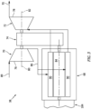
FIG. 3 is a schematic illustration of an aircraft powerplant coupled to a gearbox, where the aircraft powerplant is configured as a turbo-compounded intermittent combustion engine. -
FIG. 4 is a schematic illustration of the aircraft powerplant coupled to the gearbox, where the aircraft powerplant is configured as a turbocharged intermittent combustion engine. -
FIG. 5 is a sectional schematic illustration of a drivetrain coupling a plurality of aircraft propulsors with the aircraft powerplant. -
FIG. 6 is a schematic illustration of a compliant coupling between two driveshafts. -
FIG. 7 is a schematic illustration of the aft end portion of the aircraft configured with additional aircraft propulsors. -
FIG. 8 is a schematic illustration of the aft end portion of the aircraft configured with open rotor propulsors. -
FIG. 9 is a schematic illustration of the aft end portion of the aircraft configured with a plurality of the aircraft powerplants, where each aircraft powerplant powers its own aircraft propulsor(s). -
FIG. 10 is a sectional schematic illustration of a portion of the drivetrain with multiple pinion gears for a common propulsor. -
FIG. 1 illustrates anaircraft 20 configured as an airplane such as, but not limited to, a business jet. Thisaircraft 20 includes anaircraft airframe 22 and anaircraft propulsion system 24. Theairframe 22 ofFIG. 1 includes anaircraft fuselage 26, a plurality ofaircraft wings 28, an aircraftvertical stabilizer 30 and a plurality of aircrafthorizontal stabilizers 32. - The
propulsion system 24 is mounted with theairframe 22 and configured to generate (e.g., horizontal) thrust for propelling theaircraft 20 forward during forward aircraft flight. Thepropulsion system 24 may be located at anaft end region 34 of thefuselage 26 near thevertical stabilizer 30; however, the present disclosure is not limited to such an exemplary aircraft propulsion system location. Referring toFIG. 2 , thepropulsion system 24 includes one or more aircraft propulsors 36 (e.g., 36A and 36B), anaircraft powerplant 38 and one or more propulsor drivetrains 40 (e.g., 40A and 40B) for transferring mechanical power from thepowerplant 38 to theaircraft propulsors 36. - Each of the
aircraft propulsors aircraft propulsors FIG. 2 , for example, includes one or more bladed propulsor rotors 42 (e.g., 42A, 42B) and 44 (e.g., 44A, 44B) and a propulsor housing 46 (e.g., 46A, 46B), which propulsor housing 46 may include a propulsor case and a propulsor nacelle. Thepropulsor rotors aircraft propulsor 36. Thepropulsor rotors FIG. 2 are configured as ducted rotors; e.g., counter-rotating fan rotors. Each of thepropulsor rotors FIG. 2 , more particularly, is arranged within an internal flow duct 50 (e.g., 50A, 50B) of the propulsor housing 46. This flow duct 50 extends longitudinally (e.g., axially along the respective propulsor axis 48) through the propulsor housing 46 between and to an inlet 52 (e.g., 52A, 52B) to theaircraft propulsor 36 and an exhaust 54 (e.g., 54A, 54B) from theaircraft propulsor 36. Each of thepropulsor rotors rotor blades respective rotor disk rotor blades respective rotor disk rotor blades respective rotor disk rotor blades rotor blades respective propulsor rotor - In some embodiments, the first (e.g., upstream)
propulsor rotor 42 and the second (e.g., downstream)propulsor rotor 44 may have common dimensions; e.g., the same diameters. In other embodiments, the first and thesecond propulsor rotors - The
first propulsor rotor 42 is disposed forward and upstream of thesecond propulsor rotor 44 along therespective propulsor axis 48. Thefirst propulsor rotor 42 is configured to rotate in a first (e.g., clockwise, or counterclockwise) direction about therespective propulsor axis 48. Thesecond propulsor rotor 44 is configured to rotate in a second (e.g., counterclockwise, or clockwise) direction about therespective propulsor axis 48, which second direction is opposite the first direction. Of course, it is contemplated thefirst propulsor rotor 42 and thesecond propulsor rotor 44 may rotate in a common (the same) direction about therespective propulsor axis 48 where, for example, theaircraft propulsor 36 also includes one or more vane arrays (not shown) within the flow duct 50. - Each of the
aircraft propulsors 36 is arranged outside of theairframe 22 and itsfuselage 26. Thefirst aircraft propulsor 36A ofFIG. 2 , for example, is located on and mounted to a lateralfirst side 64A of thefuselage 26 by afirst pylon 66A. Thesecond aircraft propulsor 36B ofFIG. 2 is located on and mounted to a lateralsecond side 64B of thefuselage 26 by asecond pylon 66B, whichsecond side 64B is laterally opposite thefirst side 64A. With this arrangement, theairframe 22 and itsfuselage 26 are located laterally between thefirst aircraft propulsor 36A and thesecond aircraft propulsor 36B. - The
aircraft powerplant 38 may be configured as or otherwise include anintermittent combustion engine 68, which may also be referred to as an intermittent internal combustion (IC) engine. The term "intermittent combustion engine" may describe an internal combustion engine in which a mixture of fuel and air is intermittently (e.g., periodically) detonated within the engine. Examples of theintermittent combustion engine 68 include, but are not limited to, a reciprocating piston engine (e.g., an inline (I) engine, a V-engine, a W-engine, etc.), a rotary engine (e.g., a Wankel engine), a rotating detonation engine and a pulse detonation engine. By contrast, the term "continuous combustion engine" may describe an internal combustion engine in which a mixture of fuel and air is continuously (e.g., steadily) detonated. An example of a continuous combustion engine is a gas turbine engine. While continuous combustion engines have various benefits, theintermittent combustion engine 68 may be less expensive to manufacture and service than a comparable continuous combustion gas turbine engine. Theintermittent combustion engine 68 may also or alternatively be more fuel efficient than a comparable continuous combustion gas turbine engine. - To facilitate aircraft operation at relatively high altitudes (e.g., above 10,000 ft), the
intermittent combustion engine 68 may be configured as a forced induction intermittent combustion engine. Theintermittent combustion engine 68, for example, may be turbo-compounded (e.g., seeFIG. 3 ) and/or turbocharged (e.g., seeFIG. 4 ). Of course, it is contemplated theintermittent combustion engine 68 may alternatively be naturally aspirated where theaircraft 20 is not designed for high altitude missions. -
FIG. 3 illustrates theintermittent combustion engine 68 as a turbo-compounded intermittent combustion engine. Theaircraft powerplant 38 ofFIG. 3 , in particular, includes theintermittent combustion engine 68, acompressor section 70, aturbine section 72 and agearbox 74. Thecompressor section 70 includes abladed compressor rotor 76 and theturbine section 72 includes a bladedturbine rotor 78. Each of thesebladed rotors compressor rotor 76 is rotatable about acompressor axis 80. Theturbine rotor 78 is rotatable about aturbine axis 82, whichturbine axis 82 may be parallel (e.g., coaxial) with thecompressor axis 80. Theturbine rotor 78 is coupled to thecompressor rotor 76 through thegearbox 74; however, theturbine rotor 78 may alternatively be coupled directly to thecompressor rotor 76 by a common shaft. Theturbine rotor 78 is further coupled to an internalrotating structure 84 of theintermittent combustion engine 68 through thegearbox 74. - The
aircraft powerplant 38 ofFIG. 3 (e.g., the turbo-compounded intermittent combustion engine ofFIG. 3 , the turbocharged intermittent combustion engine ofFIG. 4 ) includes aninternal powerplant flowpath 86. This powerplant flowpath 86 is discrete (e.g., separate, fluidly decoupled, etc.) from propulsor flowpaths 88 (e.g., 88A, 88B) through the respective flow ducts 50 ofFIG. 2 . Thepowerplant flowpath 86 ofFIG. 3 extends from aninlet 89 to theaircraft powerplant 38, sequentially through thecompressor section 70, one or more combustion zones 90 (e.g., cylinder chambers, etc.) within theintermittent combustion engine 68 and theturbine section 72, to anexhaust 91 from theaircraft powerplant 38. With this arrangement, the air delivered to theintermittent combustion engine 68 is compressed by thecompressor rotor 76, and combustion products produced by combustion of the air-fuel mixture within the combustion zone(s) 90 drives rotation of theturbine rotor 78. The rotation of theturbine rotor 78 drives rotation of thecompressor rotor 76 to facilitate the compression of the incoming air to theintermittent combustion engine 68. The rotation of theturbine rotor 78 may also assist driving rotation of the rotatingstructure 84. - Referring to
FIG. 2 , theaircraft powerplant 38 and itsintermittent combustion engine 68 are arranged remote from theaircraft propulsors 36. Theaircraft powerplant 38, for example, may be arranged inside of theairframe 22. More particularly, theaircraft powerplant 38 and itsintermittent combustion engine 68 ofFIG. 2 are arranged within thefuselage 26, for example at (e.g., on, adjacent or proximate) an aft,tail end 92 of thefuselage 26 proximate the vertical stabilizer 30 (seeFIG. 1 ). Arranging theaircraft powerplant 38 and itsintermittent combustion engine 68 within theairframe 22 takes advantage of available interior space within theaircraft 20 such that theaircraft powerplant 38 does not need to be located outside of the airframe 22 (e.g., like the aircraft propulsors 36) and thereby add to aircraft drag. Furthermore, arranging theaircraft powerplant 38 and itsintermittent combustion engine 68 remote form theaircraft propulsors 36 may facilitate reducing overall sizes of the aircraft propulsors 36 and/or increase flow area of each duct 50 (e.g., compared to a turbofan engine with an integral inner core). - The
powerplant inlet 89 is configured to draw fresh air from an exterior environment outside of theaircraft 20. Thepowerplant inlet 89 ofFIG. 2 , for example, includes / is formed by one or more inlet scoops 94 (e.g., 94A, 94B). Each of these inlet scoops 94 may be arranged along an exterior of thefuselage 26. Each of the inlet scoops 94 (and thepowerplant inlet 89 more generally) may thereby direct boundary layer air flowing along thefuselage 26 into theaircraft powerplant 38. Utilizing this boundary layer air may also improve aerodynamics of thefuselage 26. - The
powerplant exhaust 91 is configured to direct the combustion products out of theaircraft powerplant 38 and out of theaircraft 20. Thepowerplant exhaust 91 ofFIG. 2 , for example, includes anexhaust nozzle 96 along the exterior of thefuselage 26 at, for example, theaft end 92 of thefuselage 26. Positioning theexhaust nozzle 96 at theaft end 92 may reduce aircraft drag and may thereby improve aircraft powerplant efficiency and/or power. In some embodiments, the combustion products may be ducted directly from theturbine section 72 to theexhaust nozzle 96; e.g., where the exhausted combustion products are un-muffled. In other embodiments, at least onemuffler 98 may be located between and fluidly coupled with theturbine section 72 and theexhaust nozzle 96. With this arrangement, the exhausted combustion products are muffled before being directed into the exterior environment outside of theaircraft 20. - Referring to
FIG. 5 , thefirst propulsor drivetrain 40A is configured to operatively couple therotating structure 84 to thepropulsor rotors second propulsor drivetrain 40B is configured to operatively couple therotating structure 84 to thepropulsor rotors structure 84, driven by combustion of the fuel-air mixture within the combustion zone(s) 90 (seeFIGS. 3 and4 ), may drive rotation of thepropulsor rotors propulsor drivetrain FIG. 5 includes a drive structure 100 (e.g., 100A, 100B), a propulsor coupling 102 (e.g., 102A, 102B) and a powerplant transmission 106 (e.g., 106A, 106B), where eachpowerplant transmissions aircraft powerplant 38 by atransmission gearbox 104. - Each of the
drive structures FIG. 5 is configured as a driveshaft 108 (e.g., 108A, 108B). Eachdriveshaft respective drive structure respective drive structure drive axis FIG. 5 is angularly offset from the propulsor axes 48. The drive axes 110, for example, may be perpendicular to the propulsor axes 48. - The
first propulsor coupling 102A is configured to connect thefirst drive structure 100A and itsdriveshaft 108A to one or more of thepropulsor rotors first aircraft propulsor 36A. Thesecond propulsor coupling 102B is configured to connect thesecond drive structure 100B and itsdriveshaft 108B to one or more of thepropulsor rotors second aircraft propulsor 36B. Each of thesepropulsor couplings propulsor rotors pinion gear 118 is mounted to or otherwise connected to and rotatable with a respective one of the drive structures 100 and itsdriveshaft 108 at arespective end 112. Thispinion gear 118 is engaged (e.g., meshed) with the respective ring gears 114, 116. Thepinion gear 118 is also located between the respective ring gears 114, 116. With this arrangement, rotating thepinion gear 118 may rotate thefirst ring gear 114 and, thus, thefirst propulsor rotor 42 in the first direction and may rotate thesecond ring gear 116 and, thus, thesecond propulsor rotor 44 in the second direction. - In some embodiments, each
propulsor coupling 102 may be configured such that therespective propulsor rotors propulsor coupling 102 may be configured such thatrespective propulsor rotors second propulsor rotor 44, for example, may rotate at a faster rotational speed than thefirst propulsor rotor 42. This speed differential may be tuned to account for thesecond propulsor rotor 44 receiving higher speed air than thefirst propulsor rotor 42. To provide such a speed differential, the ring gears 114 and 116 may have different diameters and eachring gear own pinion gear 118, 118'; e.g., seeFIG. 10 . The separate pinion gears 118 and 118' ofFIG. 10 may also have different diameters. - Referring to
FIG. 5 , thetransmission gearbox 104 is configured to couple each of the powerplant transmissions 106 (e.g., in parallel, independently, etc.) to theaircraft powerplant 38. More particularly, thetransmission gearbox 104 is configured to connect anoutput 115 from theintermittent combustion engine 68 and its rotatingstructure 84 to respective inputs 117 (e.g., 117A, 117B) of thepowerplant transmissions transmission gearbox 104 may be incorporated into one or both of thepowerplant transmissions gearbox 104 may be omitted. - Each of the
powerplant transmissions transmission input transmission transmission input transmission output transmission transmission rotor blades respective propulsor rotor transmission - Each
transmission input powerplant rotating structure 84 through thetransmission gearbox 104. Eachtransmission output propulsor rotors respective drivetrain elements aircraft powerplant 38 is transferred to theaircraft propulsor 36A and itspropulsor rotors first transmission 106A; e.g., independent of thesecond transmission 106B and the associatedsecond drivetrain 40B. Similarly, mechanical power output by theaircraft powerplant 38 is transferred to theaircraft propulsor 36B and itspropulsor rotors second transmission 106B; e.g., independent of thefirst transmission 106A and the associatedfirst drivetrain 40A. - To facilitate high speed aircraft flight, each
transmission transmission transmission powerplant rotating structure 84. Theaircraft powerplant 38 and itsintermittent combustion engine 68 may thereby operate (e.g., throughout aircraft flight) at a certain rotational speed (or within a relatively small rotational speed band), while facilitating rotation of thepropulsor rotors aircraft powerplant 38 and itsintermittent combustion engine 68 may be substantially continuously operated at a certain (e.g., maximum) power and/or efficiency, the thrust produced by theaircraft propulsors rotor blades - Including a
separate transmission 106 for each drive structure 100 and, thus, eachaircraft propulsor 36 facilitates a capability of providing a thrust differential across theaircraft 20. Thefirst powerplant transmission 106A, for example, may facilitate rotation of thepropulsor rotors second powerplant transmission 106B may independently facilitate rotation of thepropulsor rotors powerplant transmissions propulsor rotors propulsor rotors separate powerplant transmissions 106 may also provide redundancy in an unlikely event that operation of one of the propulsors 36 (e.g., rotation of thepropulsor rotors 42 and 44) needs to be terminated or otherwise changed for non-nominal operation. - Each of the
transmissions 106 ofFIG. 2 is arranged remote from theaircraft propulsors 36. Thetransmissions 106 ofFIG. 2 , for example, are arranged with theaircraft powerplant 38 within thefuselage 26. Like theaircraft powerplant 38, arranging thetransmissions 106 within theaircraft fuselage 26 takes advantage of available space without increased aircraft drag. - In some embodiments, referring to
FIG. 5 , eachdrive structure continuous driveshaft FIG. 6 , one or all of the drive structures 100 may each include at least one compliant coupling 126 (or multiple compliant couplings); e.g., flex joints. The drive structure 100 ofFIG. 6 , for example, includes a plurality of driveshafts 108 (e.g., 108' and 108"); e.g., drive structure segments. The first driveshaft 108' is connected to thesecond driveshaft 108" through thecompliant coupling 126. Thiscompliant coupling 126 may facilitate axial movement between thedriveshafts 108 along the drive axes 110 (e.g., 110' and 110"). Thecompliant coupling 126, for example, may be configured as or otherwise include a spline joint. Thecompliant coupling 126 may also or alternatively facilitate angular misalignment (e.g., slight pivoting) between thedriveshafts 108. Thecompliant coupling 126, for example, may also or alternatively be configured as or otherwise include a universal joint. With such an arrangement, the drive structure 100 may accommodate slight flexing within theairframe 22 and/or between theairframe 22 and theaircraft propulsors 36. - In some embodiments, referring to
FIG. 2 , theaircraft propulsion system 24 may be configured with asingle aircraft propulsor 36 to each (or at least one) lateral side 64 of theairframe 22 and itsfuselage 26. With this arrangement, theaircraft powerplant 38 and itsintermittent combustion engine 68, thetransmissions 106 as well as theairframe 22 and itsfuselage 26 may be located laterally between the aircraft propulsors 36 and their respective propulsor axes 48. In other embodiments, referring toFIG. 7 , theaircraft propulsion system 24 may be configured withmultiple aircraft propulsors 36 to each (or at least one) lateral side 64 of theairframe 22 and itsfuselage 26. With this arrangement, a plurality of the aircraft propulsors 36 and their respective propulsor axes 48 may be located laterally to thefirst side 64A of theaircraft powerplant 38 and itsintermittent combustion engine 68, thetransmissions 106 as well as theairframe 22 and itsfuselage 26. Similarly, a plurality of the aircraft propulsors 36 and their respective propulsor axes 48 may also or alternatively be located laterally to thesecond side 64B of theaircraft powerplant 38 and itsintermittent combustion engine 68, thetransmissions 106 as well as theairframe 22 and itsfuselage 26. - In some embodiments, referring to
FIG. 2 , thepropulsor rotors FIG. 8 , thepropulsor rotors respective aircraft propulsor 36 is configured without the propulsor housing 46 ofFIG. 2 . - In some embodiments, referring to
FIG. 2 , thepropulsion system 24 may include asingle aircraft powerplant 38 powering all of theaircraft propulsors 36. In other embodiments, referring toFIG. 9 , thepropulsion system 24 may include multiple of theaircraft powerplants 38, where eachaircraft powerplant 38 is paired with and powers its own aircraft propulsor(s) 36 through asingle transmission 106. Such an arrangement may also be provided to facilitate provision of the thrust differential laterally across theaircraft 20. - The
propulsion system elements aft end region 34 of thefuselage 26. The present disclosure, however, is not limited to such an exemplary arrangement. For example, one or more or all of thepropulsion system elements fuselage 26. In still another example, one or more or all of thepropulsion system elements airframe 22 besides thefuselage 26; e.g., a pylon, one of thewings 28, one of thestabilizers - While various embodiments of the present disclosure have been described, it will be apparent to those of ordinary skill in the art that many more embodiments and implementations are possible within the scope of the disclosure. For example, the present disclosure as described herein includes several aspects and embodiments that include particular features. Although these features may be described individually, it is within the scope of the present disclosure that some or all of these features may be combined with any one of the aspects and remain within the scope of the disclosure. Accordingly, the present disclosure is not to be restricted except in light of the attached claims and their equivalents.
Claims (15)
- An aircraft system (20), comprising:a first propulsor rotor (42A) rotatable about a first propulsor axis (48A);a first transmission (106A) coupled to the first propulsor rotor (42A);a second propulsor rotor (42B) rotatable about a second propulsor axis (48B);a second transmission (106B) coupled to the second propulsor rotor (42B); andan intermittent combustion engine (68) configured to drive rotation of the first propulsor rotor (42A) through the first transmission (106A), and to drive rotation of the second propulsor rotor (42B) through the second transmission (106B).
- The aircraft system (20) of claim 1, wherein, during at least one mode of operation:the first transmission (106A) and the second transmission (106B) are configured to facilitate rotation of the first propulsor rotor (42) and the second propulsor rotor (44) at a common rotational speed; and/orthe first transmission (106A) and the second transmission (106B) are configured to facilitate rotation of the first propulsor rotor (42A) and the second propulsor rotor (42B) at different rotational speeds.
- The aircraft system (20) of claim 1 or 2, wherein:the first propulsor rotor (42A) comprises a first ducted rotor (42) and the second propulsor rotor (42B) comprises a second ducted rotor (42B); orthe first propulsor rotor (42A) comprises a first open rotor (42A) and the second propulsor rotor (42B) comprises a second open rotor (42B).
- The aircraft system (20) of any of claims 1 to 3, wherein:the first propulsor axis (48A) is laterally spaced from the second propulsor axis (48B); andthe intermittent combustion engine (68) is located laterally between the first propulsor axis (48) and the second propulsor axis (48).
- The aircraft system (20) of any preceding claim, further comprising:a third propulsor rotor (44A) downstream of the first propulsor rotor (42A) and rotatable about the first propulsor axis (48A);the intermittent combustion engine (68) further configured to drive rotation of the third propulsor rotor (42A) through the first transmission (106A).
- The aircraft system (20) of claim 5, further comprising:a first propulsor ring gear (114) rotatable with the first propulsor rotor (42);a third propulsor ring gear (114) rotatable with the third propulsor rotor (42); anda pinion gear (118) rotatably driven by the intermittent combustion engine (68) through the first transmission (106A), the pinion gear (118) meshed with the first propulsor ring gear (114) and the third propulsor ring gear (114).
- The aircraft system (20) of claim 5, further comprising:a first propulsor ring gear (114A) rotatable with the first propulsor rotor (42A);a third propulsor ring gear (116A) rotatable with the third propulsor rotor (44A);a first pinion gear (118A) rotatably driven by the intermittent combustion engine (68) through the first transmission (106A), the first pinion gear (118) meshed with the first propulsor ring gear (114A); anda second pinion gear (118B) rotatably driven by the intermittent combustion engine (68) through the first transmission (106A), the second pinion gear (118B) meshed with the third propulsor ring gear (116A).
- The aircraft system (20) of any of claims 5 to 7, further comprising:a drivetrain (100A) coupling the intermittent combustion engine (68) to the first propulsor rotor (42A) and the third propulsor rotor (44A);the drivetrain (100A) configured to rotate the first propulsor rotor (42A) and the third propulsor rotor (44A) in opposite directions; andthe drivetrain comprising the first transmission (106A).
- The aircraft system (20) of any preceding claim, further comprising:a first drive structure (100A) coupling the first transmission (106A) to the first propulsor rotor (42); anda first coupling (102A) connecting the drive structure (100) to the first propulsor rotor (42A), the first coupling (102A) including a or the first propulsor ring gear (114A) and a or the first pinion gear (118), the first propulsor ring gear (114A) rotatable with the first propulsor rotor (42A), and the first pinion gear (118) rotatable with the drive structure (100) and meshed with the first ring gear (114A) and optionally wherein the drive structure (100A) is configured as a driveshaft (108).
- The aircraft system (20) of any preceding claim, wherein the first transmission (106A) comprises a variable speed transmission (106A).
- The aircraft system (20) of any preceding claim, wherein the intermittent combustion engine (68) comprises:a rotary engine, a piston engine, a rotating detonation engine or a pulse detonation engine; and/ora turbo-compounded intermittent combustion engine (68) or a turbocharged intermittent combustion engine (68).
- The aircraft system (20) of any preceding claim, further comprising an aircraft fuselage housing the intermittent combustion engine (68), the first transmission (106A) and the second transmission (106B), wherein the first propulsor rotor (42A) and the second propulsor rotor (42B) are located outside of the aircraft fuselage (26).
- The aircraft system (20) of claim 12, further comprising:an inlet (52) configured to direct boundary layer air flowing along the aircraft fuselage (26) to the intermittent combustion engine (68); andan exhaust (54) located at an aft end (92) of the aircraft fuselage (26), the exhaust (54) configured to direct combustion products generated by the intermittent combustion engine (68) out of the aircraft system.
- An aircraft system (20), comprising:a first propulsor (36A) including a plurality of first propulsor rotors (42A) rotatable about a first propulsor axis (48A);a first transmission (106A) coupled to the plurality of first propulsor rotors (42A);a second propulsor (36B) including a plurality of second propulsor rotors (42) rotatable about a second propulsor axis (48A);a second transmission (106B) coupled to the plurality of second propulsor rotors (42B);an intermittent combustion engine (68) configured to drive rotation of the plurality of first propulsor rotors (42A) through the first transmission (106A) and in opposing directions, and the intermittent combustion engine (68) configured to drive rotation of the plurality of second propulsor rotors (42B) through the second transmission (106B) and in opposing directions, and optionally wherein the first transmission (106A) is configured as a first variable speed transmission (106A) and the second transmission (106B) is configured as a second variable speed transmission (106B).
- An aircraft system (20), comprising:an aircraft fuselage (26);a propulsor outside of and next to the aircraft fuselage (26), the propulsor comprising a ducted propulsor rotor (42);a transmission (106) housed within the aircraft fuselage (26), the transmission (106) coupled to the propulsor (36); anda turbo-compounded intermittent combustion engine (68) housed within the aircraft fuselage (26), the turbo-compounded intermittent combustion engine (68) configured to drive rotation of the ducted propulsor rotor (42) through the transmission (106).
Applications Claiming Priority (1)
| Application Number | Priority Date | Filing Date | Title |
|---|---|---|---|
| US17/866,081 US12365469B2 (en) | 2022-07-15 | 2022-07-15 | Aircraft propulsion system with intermittent combustion engine(s) |
Publications (3)
| Publication Number | Publication Date |
|---|---|
| EP4306422A2 true EP4306422A2 (en) | 2024-01-17 |
| EP4306422A3 EP4306422A3 (en) | 2024-08-14 |
| EP4306422B1 EP4306422B1 (en) | 2026-04-01 |
Family
ID=87280953
Family Applications (1)
| Application Number | Title | Priority Date | Filing Date |
|---|---|---|---|
| EP23185410.0A Active EP4306422B1 (en) | 2022-07-15 | 2023-07-13 | Aircraft propulsion system with intermittent combustion engine(s) |
Country Status (3)
| Country | Link |
|---|---|
| US (1) | US12365469B2 (en) |
| EP (1) | EP4306422B1 (en) |
| CA (1) | CA3206808A1 (en) |
Families Citing this family (2)
| Publication number | Priority date | Publication date | Assignee | Title |
|---|---|---|---|---|
| US20240017841A1 (en) * | 2022-07-15 | 2024-01-18 | Pratt & Whitney Canada Corp. | Aircraft propulsion system with intermittent combustion engine(s) |
| US12365469B2 (en) | 2022-07-15 | 2025-07-22 | Pratt & Whitney Canada Corp. | Aircraft propulsion system with intermittent combustion engine(s) |
Family Cites Families (31)
| Publication number | Priority date | Publication date | Assignee | Title |
|---|---|---|---|---|
| US2395610A (en) * | 1943-04-30 | 1946-02-26 | Ralph C Cavallaro | Counterdrive for dual propellers |
| US2466949A (en) * | 1945-06-30 | 1949-04-12 | United Aircraft Corp | Two-speed dual rotation propeller drive |
| US2961189A (en) | 1958-12-12 | 1960-11-22 | Edmond R Doak | Vertical take-off aircraft construction |
| US3106369A (en) | 1960-02-23 | 1963-10-08 | Curtiss Wright Corp | Aircraft and method of operating same |
| US3335977A (en) | 1965-06-16 | 1967-08-15 | Ludwig F Meditz | Convertiplane |
| US4964315A (en) * | 1984-10-03 | 1990-10-23 | General Electric Company | Transmission having dual counterrotating output shafts |
| US5890441A (en) | 1995-09-07 | 1999-04-06 | Swinson Johnny | Horizontal and vertical take off and landing unmanned aerial vehicle |
| US6457670B1 (en) * | 2001-01-30 | 2002-10-01 | Roadable Aircraft Int'l | Counter rotating ducted fan flying vehicle |
| FR2864029B1 (en) | 2003-12-23 | 2006-04-07 | Eurocopter France | CONVERTIBLE AIRCRAFT COMPRISING TWO "FAN TILT" ON EITHER FUSELAGE AND FIXED "FAN" INSERTED IN FUSELAGE |
| CA2602214A1 (en) | 2007-09-12 | 2009-03-12 | James Paul Hines | Aircraft propulsion system |
| DE102008062813A1 (en) | 2008-12-23 | 2010-07-15 | Rolls-Royce Deutschland Ltd & Co Kg | Airplane with a stern-propeller engine arrangement |
| US8701381B2 (en) | 2010-11-24 | 2014-04-22 | Rolls-Royce Corporation | Remote shaft driven open rotor propulsion system with electrical power generation |
| US9540113B2 (en) | 2013-03-11 | 2017-01-10 | United Technologies Corporation | De-couple geared turbo-fan engine and aircraft |
| EP3080425A4 (en) | 2013-12-13 | 2017-09-20 | United Technologies Corporation | Transverse-mounted power turbine drive system |
| US9650954B2 (en) | 2014-02-07 | 2017-05-16 | United Technologies Corporation | Gas turbine engine with distributed fans |
| US10240521B2 (en) | 2015-08-07 | 2019-03-26 | Pratt & Whitney Canada Corp. | Auxiliary power unit with variable speed ratio |
| FR3042007B1 (en) * | 2015-10-05 | 2018-06-15 | Safran Aircraft Engines | TURBO MOTOR WITH BLOWERS DEPORTEES AND REDUCTION OF SPEED ON THE SHAFT OF THE POWER TURBINE |
| JP2017154654A (en) * | 2016-03-03 | 2017-09-07 | 双葉電子工業株式会社 | Multi-copter |
| US10352274B2 (en) | 2016-08-18 | 2019-07-16 | United Technologies Corporation | Direct drive aft fan engine |
| US10823041B2 (en) | 2017-12-19 | 2020-11-03 | Pratt & Whitney Canada Corp. | Engine assembly with plenum and remote fan |
| US10894605B2 (en) | 2018-03-13 | 2021-01-19 | U.S. Aeronautics, Inc. | Efficient low-noise aircraft propulsion system |
| US11230388B2 (en) | 2018-05-09 | 2022-01-25 | Textron Innovations Inc. | Stowable wing aircraft with dual, fuselage-mounted engines |
| US20200108915A1 (en) | 2018-10-05 | 2020-04-09 | Pratt & Whitney Canada Corp. | Engine assembly with porous surface of boundary layer suction |
| FR3090578A1 (en) | 2018-12-24 | 2020-06-26 | Airbus Operations | BLI propulsion system with three rear thrusters |
| DE102019208353A1 (en) | 2019-06-07 | 2020-12-10 | e.SAT Management GmbH | plane |
| SG11202010196TA (en) | 2019-11-29 | 2021-07-29 | Zhen Gang Ker | Land and Aerial Transportation Vehicle and Powertrain thereof |
| GB202008070D0 (en) | 2020-05-29 | 2020-07-15 | Rolls Royce Plc | Aircraft electrical power distribution |
| US20230138513A1 (en) * | 2021-10-29 | 2023-05-04 | Embraer S.A. | Twin propulsor, parallel hybrid, streamlined nacelle propulsion system |
| US20240017841A1 (en) * | 2022-07-15 | 2024-01-18 | Pratt & Whitney Canada Corp. | Aircraft propulsion system with intermittent combustion engine(s) |
| US12365469B2 (en) | 2022-07-15 | 2025-07-22 | Pratt & Whitney Canada Corp. | Aircraft propulsion system with intermittent combustion engine(s) |
| US11719166B1 (en) | 2022-07-15 | 2023-08-08 | Pratt & Whitney Canada Corp. | Aircraft propulsion system with intermittent combustion engine(s) |
-
2022
- 2022-07-15 US US17/866,081 patent/US12365469B2/en active Active
-
2023
- 2023-07-13 EP EP23185410.0A patent/EP4306422B1/en active Active
- 2023-07-13 CA CA3206808A patent/CA3206808A1/en active Pending
Also Published As
| Publication number | Publication date |
|---|---|
| US20240017842A1 (en) | 2024-01-18 |
| EP4306422A3 (en) | 2024-08-14 |
| US12365469B2 (en) | 2025-07-22 |
| EP4306422B1 (en) | 2026-04-01 |
| CA3206808A1 (en) | 2024-01-15 |
Similar Documents
| Publication | Publication Date | Title |
|---|---|---|
| US20240368997A1 (en) | Unducted thrust producing system architecture | |
| EP2930114B1 (en) | Contra-rotating open rotor distributed propulsion system | |
| US12092040B2 (en) | Selective power distribution for an aircraft propulsion system | |
| US11873767B2 (en) | Gearbox configurations for clockwise and counterclockwise propeller rotation | |
| EP4306422B1 (en) | Aircraft propulsion system with intermittent combustion engine(s) | |
| EP4282763B1 (en) | Selective power distribution for an aircraft propulsion system | |
| EP4306424A1 (en) | Aircraft propulsion system with intermittent combusion engine(s) | |
| JPH0142879B2 (en) | ||
| EP4389607B1 (en) | Hybrid aircraft propulsion system with remotely located electric machine | |
| EP4306425A1 (en) | Aircraft propulsion system with intermittent combustion engine(s) | |
| US20240059419A1 (en) | Parallel hybrid propulsion system | |
| EP4653321A2 (en) | Open rotor aircraft propulsion system with bypass flowpath | |
| EP4509703A1 (en) | Aircraft powerplant with electric powertrain | |
| EP4306423B1 (en) | Aircraft propulsion system with intermittent combustion engine(s) | |
| EP4283109A1 (en) | Thrust vectoring exhaust nozzle for aircraft propulsion system | |
| EP4282764A1 (en) | Aircraft propulsion system with adjustable thrust propulsor | |
| EP4488496A1 (en) | Aircraft propulsion system engine with multiple independent rotating structures | |
| EP4283105A1 (en) | Aircraft propulsion system with variable speed rotating structure | |
| US20240401537A1 (en) | Selective power distribution for an aircraft propulsion system |
Legal Events
| Date | Code | Title | Description |
|---|---|---|---|
| PUAI | Public reference made under article 153(3) epc to a published international application that has entered the european phase |
Free format text: ORIGINAL CODE: 0009012 |
|
| STAA | Information on the status of an ep patent application or granted ep patent |
Free format text: STATUS: THE APPLICATION HAS BEEN PUBLISHED |
|
| AK | Designated contracting states |
Kind code of ref document: A2 Designated state(s): AL AT BE BG CH CY CZ DE DK EE ES FI FR GB GR HR HU IE IS IT LI LT LU LV MC ME MK MT NL NO PL PT RO RS SE SI SK SM TR |
|
| PUAL | Search report despatched |
Free format text: ORIGINAL CODE: 0009013 |
|
| AK | Designated contracting states |
Kind code of ref document: A3 Designated state(s): AL AT BE BG CH CY CZ DE DK EE ES FI FR GB GR HR HU IE IS IT LI LT LU LV MC ME MK MT NL NO PL PT RO RS SE SI SK SM TR |
|
| RIC1 | Information provided on ipc code assigned before grant |
Ipc: F02C 7/36 20060101ALI20240708BHEP Ipc: F02C 5/00 20060101ALI20240708BHEP Ipc: F01D 15/12 20060101ALI20240708BHEP Ipc: B64D 35/02 20240101ALI20240708BHEP Ipc: B64D 27/04 20060101AFI20240708BHEP |
|
| STAA | Information on the status of an ep patent application or granted ep patent |
Free format text: STATUS: REQUEST FOR EXAMINATION WAS MADE |
|
| 17P | Request for examination filed |
Effective date: 20250213 |
|
| GRAP | Despatch of communication of intention to grant a patent |
Free format text: ORIGINAL CODE: EPIDOSNIGR1 |
|
| STAA | Information on the status of an ep patent application or granted ep patent |
Free format text: STATUS: GRANT OF PATENT IS INTENDED |
|
| INTG | Intention to grant announced |
Effective date: 20250805 |
|
| GRAJ | Information related to disapproval of communication of intention to grant by the applicant or resumption of examination proceedings by the epo deleted |
Free format text: ORIGINAL CODE: EPIDOSDIGR1 |
|
| STAA | Information on the status of an ep patent application or granted ep patent |
Free format text: STATUS: REQUEST FOR EXAMINATION WAS MADE |
|
| GRAP | Despatch of communication of intention to grant a patent |
Free format text: ORIGINAL CODE: EPIDOSNIGR1 |
|
| STAA | Information on the status of an ep patent application or granted ep patent |
Free format text: STATUS: GRANT OF PATENT IS INTENDED |
|
| INTC | Intention to grant announced (deleted) | ||
| INTG | Intention to grant announced |
Effective date: 20260113 |
|
| GRAS | Grant fee paid |
Free format text: ORIGINAL CODE: EPIDOSNIGR3 |
|
| GRAA | (expected) grant |
Free format text: ORIGINAL CODE: 0009210 |
|
| STAA | Information on the status of an ep patent application or granted ep patent |
Free format text: STATUS: THE PATENT HAS BEEN GRANTED |
|
| AK | Designated contracting states |
Kind code of ref document: B1 Designated state(s): AL AT BE BG CH CY CZ DE DK EE ES FI FR GB GR HR HU IE IS IT LI LT LU LV MC ME MK MT NL NO PL PT RO RS SE SI SK SM TR |
|
| REG | Reference to a national code |
Ref country code: CH Ref legal event code: F10 Free format text: ST27 STATUS EVENT CODE: U-0-0-F10-F00 (AS PROVIDED BY THE NATIONAL OFFICE) Effective date: 20260401 Ref country code: GB Ref legal event code: FG4D |
|
| REG | Reference to a national code |
Ref country code: IE Ref legal event code: FG4D |
|
| REG | Reference to a national code |
Ref country code: DE Ref legal event code: R096 Ref document number: 602023014343 Country of ref document: DE |