EP4306418A1 - Gondeleinlassanordnung mit verbundlippenhaut - Google Patents
Gondeleinlassanordnung mit verbundlippenhaut Download PDFInfo
- Publication number
- EP4306418A1 EP4306418A1 EP23185321.9A EP23185321A EP4306418A1 EP 4306418 A1 EP4306418 A1 EP 4306418A1 EP 23185321 A EP23185321 A EP 23185321A EP 4306418 A1 EP4306418 A1 EP 4306418A1
- Authority
- EP
- European Patent Office
- Prior art keywords
- lipskin
- inlet
- composite panel
- plenum
- back wall
- Prior art date
- Legal status (The legal status is an assumption and is not a legal conclusion. Google has not performed a legal analysis and makes no representation as to the accuracy of the status listed.)
- Granted
Links
Images


Classifications
-
- F—MECHANICAL ENGINEERING; LIGHTING; HEATING; WEAPONS; BLASTING
- F01—MACHINES OR ENGINES IN GENERAL; ENGINE PLANTS IN GENERAL; STEAM ENGINES
- F01D—NON-POSITIVE DISPLACEMENT MACHINES OR ENGINES, e.g. STEAM TURBINES
- F01D25/00—Component parts, details, or accessories, not provided for in, or of interest apart from, other groups
- F01D25/24—Casings; Casing parts, e.g. diaphragms, casing fastenings
- F01D25/26—Double casings; Measures against temperature strain in casings
-
- B—PERFORMING OPERATIONS; TRANSPORTING
- B64—AIRCRAFT; AVIATION; COSMONAUTICS
- B64D—EQUIPMENT FOR FITTING IN OR TO AIRCRAFT; FLIGHT SUITS; PARACHUTES; ARRANGEMENT OR MOUNTING OF POWER PLANTS OR PROPULSION TRANSMISSIONS IN AIRCRAFT
- B64D33/00—Arrangement in aircraft of power plant parts or auxiliaries not otherwise provided for
- B64D33/02—Arrangement in aircraft of power plant parts or auxiliaries not otherwise provided for of combustion air intakes
-
- B—PERFORMING OPERATIONS; TRANSPORTING
- B64—AIRCRAFT; AVIATION; COSMONAUTICS
- B64D—EQUIPMENT FOR FITTING IN OR TO AIRCRAFT; FLIGHT SUITS; PARACHUTES; ARRANGEMENT OR MOUNTING OF POWER PLANTS OR PROPULSION TRANSMISSIONS IN AIRCRAFT
- B64D15/00—De-icing or preventing icing on exterior surfaces of aircraft
- B64D15/02—De-icing or preventing icing on exterior surfaces of aircraft by ducted hot gas or liquid
- B64D15/06—Liquid application
- B64D15/08—Liquid application exuded from surface
-
- B—PERFORMING OPERATIONS; TRANSPORTING
- B64—AIRCRAFT; AVIATION; COSMONAUTICS
- B64D—EQUIPMENT FOR FITTING IN OR TO AIRCRAFT; FLIGHT SUITS; PARACHUTES; ARRANGEMENT OR MOUNTING OF POWER PLANTS OR PROPULSION TRANSMISSIONS IN AIRCRAFT
- B64D29/00—Power-plant nacelles, fairings or cowlings
- B64D29/06—Attaching of nacelles, fairings or cowlings
-
- B—PERFORMING OPERATIONS; TRANSPORTING
- B64—AIRCRAFT; AVIATION; COSMONAUTICS
- B64F—GROUND OR AIRCRAFT-CARRIER-DECK INSTALLATIONS SPECIALLY ADAPTED FOR USE IN CONNECTION WITH AIRCRAFT; DESIGNING, MANUFACTURING, ASSEMBLING, CLEANING, MAINTAINING OR REPAIRING AIRCRAFT, NOT OTHERWISE PROVIDED FOR; HANDLING, TRANSPORTING, TESTING OR INSPECTING AIRCRAFT COMPONENTS, NOT OTHERWISE PROVIDED FOR
- B64F5/00—Designing, manufacturing, assembling, cleaning, maintaining or repairing aircraft, not otherwise provided for; Handling, transporting, testing or inspecting aircraft components, not otherwise provided for
- B64F5/10—Manufacturing or assembling aircraft, e.g. jigs therefor
-
- F—MECHANICAL ENGINEERING; LIGHTING; HEATING; WEAPONS; BLASTING
- F01—MACHINES OR ENGINES IN GENERAL; ENGINE PLANTS IN GENERAL; STEAM ENGINES
- F01D—NON-POSITIVE DISPLACEMENT MACHINES OR ENGINES, e.g. STEAM TURBINES
- F01D25/00—Component parts, details, or accessories, not provided for in, or of interest apart from, other groups
- F01D25/02—De-icing means for engines having icing phenomena
-
- B—PERFORMING OPERATIONS; TRANSPORTING
- B64—AIRCRAFT; AVIATION; COSMONAUTICS
- B64D—EQUIPMENT FOR FITTING IN OR TO AIRCRAFT; FLIGHT SUITS; PARACHUTES; ARRANGEMENT OR MOUNTING OF POWER PLANTS OR PROPULSION TRANSMISSIONS IN AIRCRAFT
- B64D33/00—Arrangement in aircraft of power plant parts or auxiliaries not otherwise provided for
- B64D33/02—Arrangement in aircraft of power plant parts or auxiliaries not otherwise provided for of combustion air intakes
- B64D2033/0233—Arrangement in aircraft of power plant parts or auxiliaries not otherwise provided for of combustion air intakes comprising de-icing means
-
- B—PERFORMING OPERATIONS; TRANSPORTING
- B64—AIRCRAFT; AVIATION; COSMONAUTICS
- B64D—EQUIPMENT FOR FITTING IN OR TO AIRCRAFT; FLIGHT SUITS; PARACHUTES; ARRANGEMENT OR MOUNTING OF POWER PLANTS OR PROPULSION TRANSMISSIONS IN AIRCRAFT
- B64D33/00—Arrangement in aircraft of power plant parts or auxiliaries not otherwise provided for
- B64D33/02—Arrangement in aircraft of power plant parts or auxiliaries not otherwise provided for of combustion air intakes
- B64D2033/0266—Arrangement in aircraft of power plant parts or auxiliaries not otherwise provided for of combustion air intakes specially adapted for particular type of power plants
- B64D2033/0286—Arrangement in aircraft of power plant parts or auxiliaries not otherwise provided for of combustion air intakes specially adapted for particular type of power plants for turbofan engines
-
- F—MECHANICAL ENGINEERING; LIGHTING; HEATING; WEAPONS; BLASTING
- F05—INDEXING SCHEMES RELATING TO ENGINES OR PUMPS IN VARIOUS SUBCLASSES OF CLASSES F01-F04
- F05D—INDEXING SCHEME FOR ASPECTS RELATING TO NON-POSITIVE-DISPLACEMENT MACHINES OR ENGINES, GAS-TURBINES OR JET-PROPULSION PLANTS
- F05D2230/00—Manufacture
- F05D2230/40—Heat treatment
- F05D2230/41—Hardening; Annealing
-
- F—MECHANICAL ENGINEERING; LIGHTING; HEATING; WEAPONS; BLASTING
- F05—INDEXING SCHEMES RELATING TO ENGINES OR PUMPS IN VARIOUS SUBCLASSES OF CLASSES F01-F04
- F05D—INDEXING SCHEME FOR ASPECTS RELATING TO NON-POSITIVE-DISPLACEMENT MACHINES OR ENGINES, GAS-TURBINES OR JET-PROPULSION PLANTS
- F05D2230/00—Manufacture
- F05D2230/90—Coating; Surface treatment
-
- F—MECHANICAL ENGINEERING; LIGHTING; HEATING; WEAPONS; BLASTING
- F05—INDEXING SCHEMES RELATING TO ENGINES OR PUMPS IN VARIOUS SUBCLASSES OF CLASSES F01-F04
- F05D—INDEXING SCHEME FOR ASPECTS RELATING TO NON-POSITIVE-DISPLACEMENT MACHINES OR ENGINES, GAS-TURBINES OR JET-PROPULSION PLANTS
- F05D2240/00—Components
- F05D2240/10—Stators
- F05D2240/14—Casings or housings protecting or supporting assemblies within
-
- F—MECHANICAL ENGINEERING; LIGHTING; HEATING; WEAPONS; BLASTING
- F05—INDEXING SCHEMES RELATING TO ENGINES OR PUMPS IN VARIOUS SUBCLASSES OF CLASSES F01-F04
- F05D—INDEXING SCHEME FOR ASPECTS RELATING TO NON-POSITIVE-DISPLACEMENT MACHINES OR ENGINES, GAS-TURBINES OR JET-PROPULSION PLANTS
- F05D2300/00—Materials; Properties thereof
- F05D2300/10—Metals, alloys or intermetallic compounds
- F05D2300/17—Alloys
-
- F—MECHANICAL ENGINEERING; LIGHTING; HEATING; WEAPONS; BLASTING
- F05—INDEXING SCHEMES RELATING TO ENGINES OR PUMPS IN VARIOUS SUBCLASSES OF CLASSES F01-F04
- F05D—INDEXING SCHEME FOR ASPECTS RELATING TO NON-POSITIVE-DISPLACEMENT MACHINES OR ENGINES, GAS-TURBINES OR JET-PROPULSION PLANTS
- F05D2300/00—Materials; Properties thereof
- F05D2300/40—Organic materials
- F05D2300/43—Synthetic polymers, e.g. plastics; Rubber
-
- F—MECHANICAL ENGINEERING; LIGHTING; HEATING; WEAPONS; BLASTING
- F05—INDEXING SCHEMES RELATING TO ENGINES OR PUMPS IN VARIOUS SUBCLASSES OF CLASSES F01-F04
- F05D—INDEXING SCHEME FOR ASPECTS RELATING TO NON-POSITIVE-DISPLACEMENT MACHINES OR ENGINES, GAS-TURBINES OR JET-PROPULSION PLANTS
- F05D2300/00—Materials; Properties thereof
- F05D2300/60—Properties or characteristics given to material by treatment or manufacturing
- F05D2300/603—Composites; e.g. fibre-reinforced
Definitions
- Embodiments of the present disclosure generally relate to the inlet section of a nacelle, such as an engine nacelle on an aircraft.
- a nacelle includes an inlet section at a leading or front end of the nacelle.
- the nacelle may also include a fan cowl, a thrust reverser section, and an aft fairing section located behind the inlet section along a longitudinal length of the nacelle.
- the inlet section has an inner barrel that defines an air inlet duct for directing air to the fan and downstream components of the engine.
- the inner barrel may have an acoustic panel to facilitate reducing noise created by the fan and a compressor of the engine.
- a compact nacelle there are several advantages associated with a compact nacelle. For example, shortening the nacelle along the longitudinal length may improve fuel burn and reduce drag, weight, and material costs. However, shortening the inlet section undesirably results in less available volume and surface area in which to integrate noise treatment and anti-ice systems. For example, there may be less space available within the inlet section for the acoustic panel, requiring a shorter acoustic panel.
- Some known anti-ice systems direct a stream of hot engine bleed air into a channel of the inlet section defined between a front end of the inlet and a bulkhead within the inlet. The hot air stream heats the leading edge of the inlet section to melt and/or prevent the formation of ice on the exterior surface of the inlet section.
- This pneumatic, bleed air-based anti-ice system has several drawbacks, including relatively high complexity (e.g., requiring valves and conduits to control the blead air, as well as bulkheads in the inlet), reduced fuel efficiency (e.g., fuel economy) due to the use of bleed air for heating rather than propulsion, lower maximum thrust level able to be generated by the engine, and the like.
- Certain embodiments of the present disclosure provide an inlet assembly of a nacelle.
- the inlet assembly includes an inlet cowl.
- the inlet cowl includes a lipskin that has a front section which defines a leading edge of the inlet cowl.
- the front section includes a composite panel and a metallic coating disposed along an exterior surface of the composite panel to protect the composite panel from damage.
- the lipskin defines perforations that penetrate through the composite panel and the metallic coating at the front section to convey a liquid through a thickness of the lipskin onto an exterior surface of the inlet cowl.
- Certain embodiments of the present disclosure provide a method (e.g., for forming a nacelle inlet assembly).
- the method includes forming an inlet cowl that includes a leading edge.
- the inlet cowl is formed by applying a carbon fiber reinforced polymer (CFRP) material on a curved tool.
- CFRP carbon fiber reinforced polymer
- the CFRP material is cured to form a composite panel of a lipskin.
- the lipskin includes a front section that defines the leading edge of the inlet cowl.
- the inlet cowl is formed by applying a metallic coating along an exterior surface of the composite panel to protect the composite panel from damage, and by forming perforations that continuously extend through both the composite panel and the metallic coating.
- the perforations are located along the front section of the lipskin and are configured to deliver a liquid through a thickness of the lipskin onto an exterior surface of the inlet cowl.
- the inlet assembly includes an inlet cowl and a fluid ice protection system (FIPS).
- the inlet cowl includes a leading edge, an inner barrel portion, and an outer barrel portion.
- the inlet cowl has a lipskin and an acoustic panel.
- the lipskin includes a front section which defines the leading edge of the inlet cowl.
- the front section includes a composite panel and a metallic coating disposed along an exterior surface of the composite panel to protect the composite panel from damage.
- the lipskin defines perforations that penetrate through the composite panel and the metallic coating at the front section to convey a liquid through a thickness of the lipskin onto an exterior surface of the inlet cowl.
- the acoustic panel is coupled to the lipskin and extends along the inner barrel portion.
- the FIPS includes a plenum back wall affixed to an interior surface of the composite panel along the front section to define a plenum between the interior surface and a front surface of the plenum back wall.
- the FIPS includes a fluid delivery conduit coupled to the plenum back wall and configured to supply an anti-ice liquid into the plenum through an aperture in the plenum back wall for the anti-ice liquid in the plenum to penetrate through the perforations onto an exterior surface of the inlet cowl.
- This nacelle inlet assembly with composite lipskin was made with UK Government support under 22482 - UK Aerospace Research and Technology Programme. The UK Government may have certain rights in this nacelle inlet assembly with composite lipskin.
- the inlet assembly may be incorporated into a compact, short nacelle to achieve greater fuel efficiency relative to a longer nacelle.
- the inlet assembly includes an inlet cowl that has a lipskin.
- the lipskin includes a composite panel with a metallic coating along an exterior surface of the composite panel.
- the metallic coating provides an erosion shield to protect against leading edge damage.
- the metallic coating is exposed along the leading edge to sunlight, wind, moisture, debris, birds, and/or the like, and protects the composite panel from such elements.
- the composite panel is or includes carbon fiber.
- the composite panel may have a carbon fiber reinforced polymer (CFRP) material.
- the inlet assembly includes a fluid ice protection system (FIPS) that is operably connected to the inlet cowl.
- the FIPS may supply an anti-ice liquid to an interior surface of the lipskin.
- the anti-ice liquid may be a freezing point depression compound, such as a glycol-based solution.
- the lipskin of the inlet cowl may include perforations (e.g., holes) that extend through the thickness of the lipskin, such that each perforation penetrates through both the composite panel and the metallic coating.
- the perforations may be relatively small and may be laser-formed.
- the perforations may be microscopic (e.g., with micron scale diameters).
- the anti-ice liquid may weep through the perforations onto the exterior surface of the metallic coating.
- the liquid prevents the formation of ice (and removes any ice already present) along the inlet, which can be detrimental to flight and engine performance.
- the FIPS may include a plenum back wall that is coupled to the interior surface of the lipskin to define a plenum (e.g., cavity).
- the anti-ice liquid is supplied to the plenum through one or more conduits that extend from a reservoir remote from the inlet cowl.
- the FIPS may include one or more membranes within the plenum that absorb and distribute the anti-ice liquid to the perforations. For example, the membrane(s) may extend across and cover all or a majority of the perforations, such that the anti-ice fluid enters the perforations from the membrane(s).
- the lipskin has an outer barrel portion that extends aft for a longer length than at least some conventional inlet cowls.
- the outer barrel portion of the lipskin may extend aft to an interface with the fan cowl.
- the inlet cowl described herein may lack a discrete composite outer barrel that is coupled to the lipskin.
- the composite panel with metallic coating may extend from the leading edge along the outer barrel portion to the interface with the fan cowl.
- the exterior surface of the inlet cowl may be smooth and free of seams from the leading edge along the outer barrel portion to the end of the lipskin, which results in a low likelihood of turbulent air flow along the outer barrel portion.
- At least some conventional inlet cowls may include seams at interfaces between the lipskin and the outer barrel panel. The seams increase turbulence of the air flow, which is detrimental to flight and engine performance.
- the inlet cowl described herein may provide an extended natural laminar flow surface, resulting in improved aerodynamic performance.
- the inlet cowl may include support frames within an interior of the inlet cowl to mechanically support the extended length of the lipskin and withstand forces exerted on the exterior of the lipskin.
- One or more of the support frames may be open truss-like structures.
- some of the support frames may extend longitudinally, and others of the support frames may extend circumferentially.
- the support frames may be located aft of the plenum back wall of the FIPS.
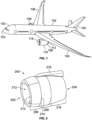
- FIG. 1 is a perspective illustration of an aircraft 100.
- the aircraft 100 may include a fuselage 102 extending from a nose 103 to an empennage 104.
- the empennage 104 may include one or more tail surfaces for directional control of the aircraft 100.
- the aircraft 100 includes a pair of wings 106 extending from the fuselage 102.
- the aircraft 100 includes one or more propulsion systems 108 which are optionally supported by the wings 106.
- each propulsion system 108 may include or represent a gas turbine engine 119 surrounded by a nacelle 110.
- one or more of the propulsion systems 108 may include motor-driven rotors surrounded by the nacelle 110 instead of a gas turbine engine.
- the motor of such propulsion systems 108 may be powered by electrical energy supplied by an onboard battery system and/or an onboard electrical energy generation system.
- the nacelle 110 may have an exhaust nozzle 112 (e.g., a primary exhaust nozzle and a fan nozzle) at an aft end of the propulsion system 108.
- FIG 2 illustrates an embodiment of a nacelle 200 of a propulsion system of an aircraft according to an embodiment.
- the nacelle 200 may be one of the nacelles 110 of the propulsion systems 108 shown in Figure 1 .
- the nacelle 200 extends a length from a front end 202 of the nacelle 200 to an aft end 204 of the nacelle 200 (opposite the front end 202).
- the nacelle 200 may include an inlet cowl 206 and a fan cowl 208.
- the inlet cowl 206 defines a leading edge 210 of the nacelle 200 at the front end 202, to direct air into a core 212 of the nacelle 200.
- the fan cowl 208 is aft of the inlet cowl 206 and is connected to the inlet cowl 206.
- the fan cowl 208 may connect to and extend from an aft edge 214 of the inlet cowl 206.
- the fan cowl 208 may surround one or more fans mounted at a forward end of the engine within the core 212.
- the nacelle 200 may include a mount 216 for securing the nacelle 200 and the rotary components held by the nacelle 200 to the aircraft.
- the mount 216 may be a pylon.
- the nacelle 200 includes at least one aft section 218 that is disposed aft of the fan cowl 208 along the length of the nacelle 200.
- the aft section(s) 218 may surround engine components such as a compressor, combustion chamber (or combustor), and turbine.
- the aft section(s) 218 may include or represent a thrust reverser, aft fairing, or the like.
- the aft section(s) 218 may define the aft end 204 and an aft nozzle through which air and exhaust products are emitted from the propulsion system.
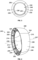
- Figure 3 is a front view of the inlet cowl 206 shown in Figure 2 .
- Figure 4 is a perspective view of the inlet cowl 206 shown in Figures 2 and 3 , showing the aft edge 214 of the inlet cowl 206.
- the inlet cowl 206 has an annular barrel shape that defines a central opening 230.
- the term "annular barrel shape" means that the inlet cowl 206 defines a closed, ring-like shape when viewed from the front.
- the inlet cowl 206 may have a generally cylindrical shape.
- the leading edge 210 may be circular.
- the inlet cowl 206 directs air through the central opening 230 into the core 212 of the nacelle 200 shown in Figure 2 .
- the inlet cowl 206 has an outer barrel portion 232 radially outside of the leading edge 210 and an inner barrel portion 234 radially inside of the leading edge 210.
- the inner barrel portion 234 may define the central opening 230, and operates as an intake duct to supply air into the core 212 for the rotary components.
- the outer barrel portion 232 surrounds the inner barrel portion 234.
- the outer barrel portion 232 may be radially offset from the inner barrel portion 234 to define a cavity 242 within the inlet cowl 206.
- the cavity 242 is closed at a front end 244 of the inlet cowl 206, and open at a rear or aft end 246.
- the inlet cowl 206 extends a length along a central longitudinal axis 207.
- the inlet cowl 206 includes a lipskin 236 and an acoustic panel 238.
- the lipskin 236 may define the leading edge 210 and the outer barrel portion 232.
- the acoustic panel 238 is coupled to the lipskin 236 along the inner barrel portion 234, and the acoustic panel 238 defines a length of the inner barrel portion 234.
- the lipskin 236 may define a front section of the inner barrel portion 234 along the length of the inlet cowl 206, and the acoustic panel 238 may define an aft section of the inner barrel portion 234, which extends to an inner aft edge 235.
- the acoustic panel 238 is located forward of the fan cowl 208.
- the acoustic panel 238 may be located in relatively close proximity to one or more fans or other rotary equipment.
- the acoustic panel 238 may have a plurality of perforations for absorbing noise generated by the rotary equipment and/or the airflow passing through the inlet cowl 206.
- the inlet cowl 206 may represent a portion of an inlet assembly 240.
- the inlet assembly 240 may include at least a portion of an anti-ice FIPS (shown in Figure 6 ) integrated within the cavity 242 of the inlet cowl 206.
- the FIPS supplies an anti-ice fluid onto an exterior surface 248 of the inlet cowl 206 to prohibit ice formation on the exterior surface 248.
- the exterior surface 248 that receives the anti-ice fluid is at and around the leading edge 210.
- the exterior surface 248 is exposed to the elements, such as sunlight, moisture, debris, wind, birds, etc.
- the inlet assembly 240 may include support frames 250 within the cavity 242 of the inlet cowl to mechanically support the lipskin 236 and the acoustic panel 238.
- the support frames 250 may help withstand pressure and other forces exerted on the exterior surface 248.
- One or more of the support frames 250 may be open truss-like structures that enable air flow through openings in the support frames 250.
- the inlet assembly 240 may lack bulkheads that partition the cavity 242 into multiple channels or regions that are blocked off from each other (e.g., fluidly isolated from each other). Avoiding bulkheads which sub-divide the cavity may reduce the complexity of manufacturing the inlet assembly 240 relative to conventional inlets.
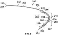
- FIG. 5 is a cross-sectional view of a portion of the inlet assembly 240 according to an embodiment.
- the illustrated portion shows the lipskin 236 of the inlet cowl 206 without the acoustic panel 238.
- the acoustic panel 238 may couple to an inner edge 254 of the lipskin 236 during the assembly process.
- the lipskin 236 in the illustrated embodiment has a curved shape that radially and longitudinally extends forward from the inner edge 254 to the leading edge 210, and then rearward to an outer, aft edge 256 of the lipskin 236.
- the lipskin 236 may be relatively thin.
- the area of the lipskin 236 that includes the leading edge 210 and the areas immediately radially adjacent to the leading edge 210 is referred to herein as a front section 258 of the lipskin 236.
- the outer, aft edge 256 may define the aft edge 214 of the inlet cowl 206, such that the lipskin 236 extends the full length of the inlet cowl 206 along the outer barrel portion 232.
- the exterior surface 248 of the inlet cowl 206 is smooth and defined by a single, continuous construct (e.g., the lipskin 236) along the entire length of the outer barrel portion 232.
- the inlet assembly 240 described herein may provide a longer and/or larger surface area along which the air flow is laminar, relative to the inlet size, than conventional inlets.
- the inlet assembly 240 may include a plenum back wall 260 that is affixed to the inlet cowl 206.
- the plenum back wall 260 is a component of an anti-ice FIPS 262.
- the plenum back wall 260 is disposed within the cavity 242 of the inlet cowl 206 and extends along the front section 258 of the lipskin 236.
- the plenum back wall 260 may be bonded, directly or indirectly, to an interior surface 264 of the lipskin 236.
- the lipskin 236 includes integrated protrusions 266 that serve as mounts on which to affix the plenum back wall 260.
- the protrusions 266 may be integral to the lipskin 236 and define sections of the interior surface 264.
- the protrusions 266 may be discrete components that are themselves mounted to the interior surface 264 and serve to indirectly secure the plenum back wall 260 to the lipskin 236.
- the plenum back wall 260 is mounted to the inlet cowl 206 to define a plenum 267 (e.g., fluid manifold) for receiving and containing the anti-ice liquid of the FIPS 262.
- the plenum 267 is defined between the interior surface 264 of the lipskin 236 and a front surface 268 of the back wall 260.
- the plenum 266 may be located along the front section 258 of the lipskin 236 only, such that the plenum 266 does not extend along the outer barrel portion 232.
- Figure 6 illustrates an enlarged, schematic rendering of the inlet assembly 240 at the leading edge 210 according to an embodiment.
- the illustrated components in Figure 6 are depicted for ease of description, and may not be drawn to scale and/or in the actual shapes as would be present in a prototype.
- the lipskin 236 in an embodiment is a stack-up of multiple different layers.
- the lipskin 236 may include at least a composite panel 270 and a metallic coating 272.
- the metallic coating 272 is exterior of the composite panel 270 to provide an erosion shield that protects the composite panel 270 from leading edge damage.
- the metallic coating 272 may define the exterior surface 248 of the inlet cowl 206 along all of the surface area of the inlet cowl 206 that is exposed to the environmental elements.
- the composite panel 270 and metallic coating 272 may extend the full length of the lipskin 236.
- the composite panel 270 has an interior surface 274 and an exterior surface 276 opposite the interior surface 274.
- the interior surface 274 may define the interior surface 264 of the lipskin 236.
- the metallic coating 272 is disposed along the exterior surface 276 of the composite panel 270.
- the metallic coating 272 is indirectly connected to the exterior surface 276 via one or more intervening layers.
- the one or more intervening layers may include an electrically conductive layer 278 that is provided to assist with the application of the metallic coating 272 on the composite panel 270.
- the conductive layer 278 may be a metallic material that has a different composition than the metallic coating 272.
- the composite panel 270 is or includes carbon fiber.
- the composite panel 270 may have a carbon fiber reinforced polymer (CFRP) material.
- the polymer may be a thermoplastic or the like.
- the metallic coating 272 may be a metal alloy.
- the metallic coating 272 in an embodiment is a nickel-cobalt (NiCo) alloy.
- the metallic coating 272 may be deposited onto the lipskin 236 to solidify and harden.
- the metallic coating 272 is applied via electroplating.
- the metallic coating 272 may be a NiCo alloy that is electroplated onto the lipskin 236.
- the lipskin 236 may define multiple perforations 280 that penetrate the thickness of the lipskin 236 along the front section 258.
- the perforations 280 may extend continuously through the composite panel 270, the conductive layer 278, and the metallic coating 272.
- the perforations 280 are aligned with and open to the plenum 267, such that the perforations 280 receive anti-ice liquid 282 from the plenum 267.
- the characteristics of the perforations 280 e.g., diameter, location, percent-open-area, etc.
- the perforations 280 have micron scale diameters.
- the microscopic perforations 280 may be formed via a laser drilling technique.
- the tiny perforations 280 enable to the liquid 282 under pressure to slowly weep through the perforations 280 onto the exterior surface 248.
- the anti-ice liquid 282 may be a solution that provides freezing point depression.
- the anti-ice liquid 282 may be an ethylene glycol-based solution.
- the illustrated components of the FIPS 262 in the inlet assembly 240 may include the plenum back wall 260, a fluid delivery conduit 284 that is coupled to the plenum back wall 260, and one or more membranes 286.
- the conduit 284 may be a duct, tube, or the like that provides a path from a fluid reservoir to the plenum 267.
- the anti-ice liquid 282 may be pumped through the conduit 284 into the plenum 267 through an aperture in the back wall 260.
- the one or more membranes 286 are disposed within the plenum 267 (e.g., between the lipskin 236 and the back wall 260) and receive the anti-ice liquid 282.
- a single membrane 286 is shown in Figure 6 .
- the membrane 286 may be designed to absorb and distribute the anti-ice liquid 282 to the perforations 280.
- the membrane 286 may extend across and cover all or a majority of the perforations 280.
- the membrane 286 may spread the liquid 282 along a length of the membrane 286 which supports a more uniform distribution of the liquid 282 among the perforations 280.
- the membrane 286 optionally may be a porous material, such as an open-celled foam material.
- the plenum back wall 260 includes first and second flanges 288 at respective ends of the back wall 260.
- the flanges 288 are secured to the protrusions 266 of the lipskin 236 along respective contact interfaces 290.
- the flanges 288 may be bonded to the protrusions 266 at the contact interfaces 290.
- the bonding may be accomplished via application of an adhesive, a heat treatment, and/or the like.
- the contact interfaces 290 are angled transverse to the tangent of the interior surface 264 of the lipskin 236 proximate to the contact interfaces 290 to enhance retention of the plenum back wall 260 to the lipskin 236.
- the contact interfaces 290 extend along ramp surfaces 296 of the protrusions 266.
- the contact interfaces 290 have vectors 292 that are not parallel to the tangent 294 of the interior surface 262.
- the contact interfaces 290 are angled to shift the pressure loading dynamics along the bonded interfaces 290 and enable the plenum back wall 260 to withstand more force before separating from the lipskin 236, relative to bonding the back wall 260 to the lipskin 236 without the protrusions 266.
- the plenum 267 may experience pressure that tends to force the plenum back wall 260 away from the leading edge 210, as indicated by the force arrows 298.
- the composite panel 270 and the protrusions 266 are not metallic, so the plenum back wall 260 cannot be welded to the lipskin 236.
- the protrusions 266 may be composed of a rigid, closed-cell foam.
- Figure 7 is a cross-sectional view of a nose portion of the inlet assembly 240 according to an embodiment.
- Figure 8 is an enlarged view of a segment of the nose portion shown in Figure 7 .
- the views in Figures 7 and 8 may be more accurate in terms of scale and shapes of the components relative to the illustration in Figure 6 .
- Figure 7 shows the leading edge 210 of the lipskin 236, the plenum back wall 260, the protrusions 266, and the membrane 286.
- the thin membrane 286 is disposed within the plenum 267.
- the flanges 288 of the back wall 260 are secured to the ramp surfaces 296 of the protrusions 266, as described with reference to Figure 6 .
- the plenum back wall 260 may be a composite structure.
- the back wall 260 may include a core layer 302 sandwiched between two outer layers 304.
- the core layer 302 may be a honeycomb structure.
- the protrusions 266 may include a rigid, closed-cell foam material. The protrusions 266 may be integrated onto the lipskin 236, such as formed with the composite panel 270.
- Figure 9 is a cross-sectional view of a portion of the inlet assembly 240 according to an embodiment.
- Figure 9 shows the acoustic panel 238 longitudinally extending along the inner barrel portion 234, and the lipskin 236 longitudinally extending the length of the outer barrel portion 232.
- the plenum back wall 260 is disposed at the front end of the cavity 242, interior of the leading edge 210.
- the inlet assembly 240 may include support frames within the cavity 242 to mechanically support the extended length of the lipskin 236 and withstand forces exerted on the lipskin 236 to maintain the shape of the inlet cowl 206.
- the support frames include longitudinally extending support frames 322 that are circumferentially spaced apart.
- the support frames may also include circumferentially extending support frames 324.
- the circumferentially extending support frames 324 may be located proximate to the aft edge 214 of the inlet cowl 206.
- the support frames 324 may be coupled to a flange 326 mounted to an aft edge 328 of the acoustic panel 238.
- the support frames 324 may be perpendicular to the support frames 322.
- the support frames 322, 324 may all extend from the outer barrel portion 232 to the inner barrel portion 234.
- the support frames 322, 324 are open, truss-like structures that permit fluid flow through openings 330 in the frames 322, 324.
- the support frames 322, 324 may be rearward or aft of the plenum back wall 260.
- the outer barrel portion 232 may extend aft beyond the aft edge 328 of the acoustic panel 238.
- the inlet assembly 240 may include one or more triangular support frames 332 to support the overhanging, cantilevered portion 334 of the outer barrel portion 232.
- FIG 10 is a schematic diagram depicting a process of assembling an inlet assembly according to an embodiment.
- the inlet assembly manufactured by the process may be the inlet assembly 240 shown in Figures 4 through 9 .
- a curved tool 310 is prepped for a layup process.
- the curved tool 310 may be a mold or mandrel.
- the tool 310 may have a shape that corresponds to a desired shape of the inlet cowl.
- CFRP carbon fiber reinforced polymer
- the layup process may be an automated fiber placement (AFP) process in which multiple layers of fiber-reinforced material are applied on the tool 310.
- AFP automated fiber placement
- the layers may be tows or bundles of carbon fibers impregnated with an epoxy resin.
- the tows may be applied in different orientations relative to one another.
- the protrusions 266 of the lipskin 236 may be formed during the layup step shown in box 402.
- the composite panel 270 may then be cured via a heat treatment and removed from the tool 310.
- the conductive layer 278 may be applied to the exterior surface 276 of the composite panel 270.
- non-plated areas of the composite panel 270 are masked by a maskant 312.
- the conductive layer 278, if present, may be co-cured at box 410.
- the metallic coating 272 is applied on the composite panel 270 (and conductive layer 278) by electroplating.
- the metallic coating 272 is shown in the inset enlarged view in box 414.
- the maskant is removed from the structure, yielding the lipskin 236 (or stack).
- the lipskin 236 is laser drilled to form perforations 280 through the thickness thereof in the front section 258.
- the membrane 286 is applied along the interior surface 264 of the lipskin 236 to cover the perforations 280.
- Box 422 shows a portion of the completed inlet assembly 240, similar to the view in Figure 7 .
- the assembly process may include additional steps not depicted in Figure 10 , such as bonding the plenum back wall 260 to the composite panel 270 and connecting the fluid delivery conduit 284 to the plenum back wall 260. Additional portions of the FIPS 262 may need to be assembled before the FIPS 262 is operational.
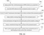
- FIG 11 is a flow chart 500 for a method of forming an inlet cowl of a nacelle inlet assembly according to an embodiment.
- the method may be performed to form the inlet cowl 206 shown in Figure 2 .
- the method optionally may include at least one additional step than shown, at least one fewer step than shown, and/or at least one different step than shown in Figure 11 .
- the inlet cowl 206 is formed to include a leading edge 210 and an outer barrel portion 232, where the outer barrel portion extends to an aft edge 214 of the inlet cowl 206.
- CFRP carbon fiber reinforced polymer
- the CFRP material is cured to form a composite panel 270 of a lipskin 236.
- the lipskin 236 includes a front section 258 that defines the leading edge 210 of the inlet cowl 206.
- first and second protrusions 266 are formed that project from the interior surface 274 of the composite panel 270.
- a metallic coating 272 is applied along an exterior surface 276 of the composite panel 270 to protect the composite panel 270 from damage. Applying the metallic coating 272 may include electroplating the metallic coating 272 along the composite panel 270.
- the CFRP material is applied and cured, and the metallic coating 272 is applied such that the composite panel 270 and the metallic coating 272 of the lipskin 236 extend from the leading edge 210 to the aft edge 214 of the outer barrel portion 232.
- perforations 280 are formed that continuously extend through both the composite panel 270 and the metallic coating 272.
- the perforations 280 may be located along the front section 258 of the lipskin 236 and configured to deliver a liquid through a thickness of the lipskin 236 onto an exterior surface 248 of the inlet cowl 206.
- the perforations 280 may be formed by laser drilling the perforations to have micron scale diameters.
- a membrane 286 may be applied along the interior surface 274 of the composite panel 270 along the front section 258. The membrane 286 may distribute the liquid among the perforations 280.
- a plenum back wall 260 is bonded to the interior surface 274 of the composite panel 270 along the front section 258 to define a plenum 267 between the interior surface 274 and a front surface 268 of the plenum back wall 260.
- ramp surfaces 296 of the first and second protrusions 266 of the composite panel 270 may be bonded to first and second flanges 288, respectively, of the plenum back wall 260.
- the membrane 286 may be contained within the plenum 267 when the plenum back wall 260 is bonded to the composite panel 270.
- a structure, limitation, or element that is "configured to” perform a task or operation is particularly structurally formed, constructed, or adapted in a manner corresponding to the task or operation.
- an object that is merely capable of being modified to perform the task or operation is not “configured to” perform the task or operation as used herein.
Landscapes
- Engineering & Computer Science (AREA)
- Aviation & Aerospace Engineering (AREA)
- Mechanical Engineering (AREA)
- General Engineering & Computer Science (AREA)
- Manufacturing & Machinery (AREA)
- Transportation (AREA)
- Chemical & Material Sciences (AREA)
- Combustion & Propulsion (AREA)
- Laminated Bodies (AREA)
- Body Structure For Vehicles (AREA)
Applications Claiming Priority (2)
| Application Number | Priority Date | Filing Date | Title |
|---|---|---|---|
| US202263368547P | 2022-07-15 | 2022-07-15 | |
| US18/165,461 US12163440B2 (en) | 2022-07-15 | 2023-02-07 | Nacelle inlet assembly with composite lipskin |
Publications (2)
| Publication Number | Publication Date |
|---|---|
| EP4306418A1 true EP4306418A1 (de) | 2024-01-17 |
| EP4306418B1 EP4306418B1 (de) | 2025-09-03 |
Family
ID=87280990
Family Applications (1)
| Application Number | Title | Priority Date | Filing Date |
|---|---|---|---|
| EP23185321.9A Active EP4306418B1 (de) | 2022-07-15 | 2023-07-13 | Gondeleinlassanordnung mit verbundlippenhaut |
Country Status (2)
| Country | Link |
|---|---|
| US (1) | US12163440B2 (de) |
| EP (1) | EP4306418B1 (de) |
Families Citing this family (1)
| Publication number | Priority date | Publication date | Assignee | Title |
|---|---|---|---|---|
| US12116140B2 (en) * | 2023-02-20 | 2024-10-15 | The Boeing Company | Inlet outer barrel segmented attach flange |
Citations (5)
| Publication number | Priority date | Publication date | Assignee | Title |
|---|---|---|---|---|
| US4434201A (en) * | 1981-11-13 | 1984-02-28 | T.K.S. (Aircraft De-Icing) Limited | Porous panel |
| US5944287A (en) * | 1996-07-02 | 1999-08-31 | Rolls-Royce Plc | Ice protection for porous structure |
| US7681838B2 (en) * | 2005-04-22 | 2010-03-23 | Rohr, Inc. | Aircraft engine nacelle inlet having access opening for electrical ice protection system |
| US9771866B2 (en) * | 2015-01-29 | 2017-09-26 | Rohr, Inc. | High temperature composite inlet |
| US20190093557A1 (en) * | 2017-09-22 | 2019-03-28 | The Boeing Company | Advanced inlet design |
Family Cites Families (20)
| Publication number | Priority date | Publication date | Assignee | Title |
|---|---|---|---|---|
| US4021008A (en) * | 1974-05-22 | 1977-05-03 | Fritz Eichenauer | Device for preventing ice formation on parts of aircraft |
| US4749150A (en) | 1985-12-24 | 1988-06-07 | Rohr Industries, Inc. | Turbofan duct with noise suppression and boundary layer control |
| US5011098A (en) * | 1988-12-30 | 1991-04-30 | The Boeing Company | Thermal anti-icing system for aircraft |
| US5297765A (en) | 1992-11-02 | 1994-03-29 | Rohr, Inc. | Turbine engine nacelle laminar flow control arrangement |
| US7047725B2 (en) | 2003-05-28 | 2006-05-23 | Rohr, Inc. | Assembly and method for aircraft engine noise reduction |
| US7588212B2 (en) | 2003-07-08 | 2009-09-15 | Rohr Inc. | Method and apparatus for noise abatement and ice protection of an aircraft engine nacelle inlet lip |
| US7291815B2 (en) | 2006-02-24 | 2007-11-06 | Goodrich Corporation | Composite ice protection heater and method of producing same |
| US7923668B2 (en) | 2006-02-24 | 2011-04-12 | Rohr, Inc. | Acoustic nacelle inlet lip having composite construction and an integral electric ice protection heater disposed therein |
| US7835130B2 (en) * | 2007-10-05 | 2010-11-16 | The Boeing Company | Method and apparatus for lightning protection of a composite structure |
| US7837150B2 (en) | 2007-12-21 | 2010-11-23 | Rohr, Inc. | Ice protection system for a multi-segment aircraft component |
| US9511562B2 (en) | 2012-07-03 | 2016-12-06 | Rohr, Inc. | Nanoreinforced films and laminates for aerospace structures |
| US8919494B2 (en) | 2012-07-31 | 2014-12-30 | Rohr, Inc. | Electric heater for integration into an aircraft acoustic panel |
| WO2015017095A2 (en) * | 2013-07-09 | 2015-02-05 | United Technologies Corporation | Plated polymer nosecone |
| GB201406277D0 (en) * | 2014-04-08 | 2014-05-21 | Rolls Royce Deutschland | A gas turbine inlet |
| US10000277B2 (en) * | 2014-10-16 | 2018-06-19 | Rohr, Inc. | Perforated surface for suction-type laminar flow control |
| US20160215700A1 (en) | 2015-01-23 | 2016-07-28 | Rohr, Inc. | Inner fixed structure acoustic panel with directional perforations |
| US9732677B1 (en) | 2016-05-12 | 2017-08-15 | Rohr, Inc. | Broadband acoustic panels coupled with large secondary cavities to attenuate low frequencies |
| US10738738B2 (en) | 2016-06-17 | 2020-08-11 | Rohr, Inc. | Nacelle with bifurcation extension and integral structural reinforcement |
| US11261786B2 (en) | 2018-08-06 | 2022-03-01 | Rohr, Inc. | Continuous slanted cell septum |
| US11174815B2 (en) | 2018-09-14 | 2021-11-16 | Rohr, Inc. | Inlet deep cavity flutter liner |
-
2023
- 2023-02-07 US US18/165,461 patent/US12163440B2/en active Active
- 2023-07-13 EP EP23185321.9A patent/EP4306418B1/de active Active
Patent Citations (5)
| Publication number | Priority date | Publication date | Assignee | Title |
|---|---|---|---|---|
| US4434201A (en) * | 1981-11-13 | 1984-02-28 | T.K.S. (Aircraft De-Icing) Limited | Porous panel |
| US5944287A (en) * | 1996-07-02 | 1999-08-31 | Rolls-Royce Plc | Ice protection for porous structure |
| US7681838B2 (en) * | 2005-04-22 | 2010-03-23 | Rohr, Inc. | Aircraft engine nacelle inlet having access opening for electrical ice protection system |
| US9771866B2 (en) * | 2015-01-29 | 2017-09-26 | Rohr, Inc. | High temperature composite inlet |
| US20190093557A1 (en) * | 2017-09-22 | 2019-03-28 | The Boeing Company | Advanced inlet design |
Also Published As
| Publication number | Publication date |
|---|---|
| EP4306418B1 (de) | 2025-09-03 |
| US12163440B2 (en) | 2024-12-10 |
| US20240018883A1 (en) | 2024-01-18 |
Similar Documents
| Publication | Publication Date | Title |
|---|---|---|
| JP7223536B2 (ja) | 先進インレット設計 | |
| JP5815942B2 (ja) | ターボ機械のナセルおよび防氷装置、ならびにその方法 | |
| EP3009346B1 (de) | Perforierte oberfläche für laminare grenzschichtkontrolle vom typ saugen | |
| EP4306420B1 (de) | Gondeleinlassanordnung mit akustikplatte | |
| US12281587B2 (en) | Nacelle inlet assembly that promotes laminar flow | |
| EP3594127B1 (de) | Aktives laminares durchflusskontrollsystem mit verbundplatte | |
| EP4306418A1 (de) | Gondeleinlassanordnung mit verbundlippenhaut | |
| US12448151B2 (en) | Method for producing a perforated nacelle inlet assembly | |
| US12227297B2 (en) | Aircraft fluid ice protection system | |
| US10823057B2 (en) | Outlet tube vent with flow energizing features | |
| US12448698B2 (en) | Method for producing a structural material stack | |
| CN117401151A (zh) | 具有复合材料唇缘蒙皮的短舱入口组合件 | |
| CN117401168A (zh) | 具有声学面板的短舱出口组件 | |
| US20220042454A1 (en) | Nacelle air intake with an acoustic panel | |
| CN117401169A (zh) | 飞行器流体防冰系统 | |
| EP4400290A1 (de) | Herstellung einer kanalstruktur mit übergeflochtener webfaserhülse | |
| US12194700B2 (en) | Forming duct structure with overbraided woven fiber sleeve |
Legal Events
| Date | Code | Title | Description |
|---|---|---|---|
| PUAI | Public reference made under article 153(3) epc to a published international application that has entered the european phase |
Free format text: ORIGINAL CODE: 0009012 |
|
| STAA | Information on the status of an ep patent application or granted ep patent |
Free format text: STATUS: THE APPLICATION HAS BEEN PUBLISHED |
|
| AK | Designated contracting states |
Kind code of ref document: A1 Designated state(s): AL AT BE BG CH CY CZ DE DK EE ES FI FR GB GR HR HU IE IS IT LI LT LU LV MC ME MK MT NL NO PL PT RO RS SE SI SK SM TR |
|
| STAA | Information on the status of an ep patent application or granted ep patent |
Free format text: STATUS: REQUEST FOR EXAMINATION WAS MADE |
|
| 17P | Request for examination filed |
Effective date: 20240716 |
|
| RBV | Designated contracting states (corrected) |
Designated state(s): AL AT BE BG CH CY CZ DE DK EE ES FI FR GB GR HR HU IE IS IT LI LT LU LV MC ME MK MT NL NO PL PT RO RS SE SI SK SM TR |
|
| GRAP | Despatch of communication of intention to grant a patent |
Free format text: ORIGINAL CODE: EPIDOSNIGR1 |
|
| STAA | Information on the status of an ep patent application or granted ep patent |
Free format text: STATUS: GRANT OF PATENT IS INTENDED |
|
| RIC1 | Information provided on ipc code assigned before grant |
Ipc: B64D 15/08 20060101ALI20250401BHEP Ipc: B64D 33/02 20060101ALI20250401BHEP Ipc: B64D 15/06 20060101AFI20250401BHEP |
|
| INTG | Intention to grant announced |
Effective date: 20250414 |
|
| GRAS | Grant fee paid |
Free format text: ORIGINAL CODE: EPIDOSNIGR3 |
|
| P01 | Opt-out of the competence of the unified patent court (upc) registered |
Free format text: CASE NUMBER: APP_29605/2025 Effective date: 20250622 |
|
| GRAA | (expected) grant |
Free format text: ORIGINAL CODE: 0009210 |
|
| STAA | Information on the status of an ep patent application or granted ep patent |
Free format text: STATUS: THE PATENT HAS BEEN GRANTED |
|
| AK | Designated contracting states |
Kind code of ref document: B1 Designated state(s): AL AT BE BG CH CY CZ DE DK EE ES FI FR GB GR HR HU IE IS IT LI LT LU LV MC ME MK MT NL NO PL PT RO RS SE SI SK SM TR |
|
| REG | Reference to a national code |
Ref country code: CH Ref legal event code: EP |
|
| REG | Reference to a national code |
Ref country code: DE Ref legal event code: R096 Ref document number: 602023006284 Country of ref document: DE |
|
| REG | Reference to a national code |
Ref country code: IE Ref legal event code: FG4D |
|
| REG | Reference to a national code |
Ref country code: NL Ref legal event code: MP Effective date: 20250903 |
|
| PG25 | Lapsed in a contracting state [announced via postgrant information from national office to epo] |
Ref country code: NO Free format text: LAPSE BECAUSE OF FAILURE TO SUBMIT A TRANSLATION OF THE DESCRIPTION OR TO PAY THE FEE WITHIN THE PRESCRIBED TIME-LIMIT Effective date: 20251203 |
|
| REG | Reference to a national code |
Ref country code: LT Ref legal event code: MG9D |
|
| PG25 | Lapsed in a contracting state [announced via postgrant information from national office to epo] |
Ref country code: FI Free format text: LAPSE BECAUSE OF FAILURE TO SUBMIT A TRANSLATION OF THE DESCRIPTION OR TO PAY THE FEE WITHIN THE PRESCRIBED TIME-LIMIT Effective date: 20250903 |
|
| PG25 | Lapsed in a contracting state [announced via postgrant information from national office to epo] |
Ref country code: HR Free format text: LAPSE BECAUSE OF FAILURE TO SUBMIT A TRANSLATION OF THE DESCRIPTION OR TO PAY THE FEE WITHIN THE PRESCRIBED TIME-LIMIT Effective date: 20250903 |
|
| PG25 | Lapsed in a contracting state [announced via postgrant information from national office to epo] |
Ref country code: GR Free format text: LAPSE BECAUSE OF FAILURE TO SUBMIT A TRANSLATION OF THE DESCRIPTION OR TO PAY THE FEE WITHIN THE PRESCRIBED TIME-LIMIT Effective date: 20251204 |
|
| PG25 | Lapsed in a contracting state [announced via postgrant information from national office to epo] |
Ref country code: SE Free format text: LAPSE BECAUSE OF FAILURE TO SUBMIT A TRANSLATION OF THE DESCRIPTION OR TO PAY THE FEE WITHIN THE PRESCRIBED TIME-LIMIT Effective date: 20250903 |
|
| PG25 | Lapsed in a contracting state [announced via postgrant information from national office to epo] |
Ref country code: LV Free format text: LAPSE BECAUSE OF FAILURE TO SUBMIT A TRANSLATION OF THE DESCRIPTION OR TO PAY THE FEE WITHIN THE PRESCRIBED TIME-LIMIT Effective date: 20250903 |
|
| PG25 | Lapsed in a contracting state [announced via postgrant information from national office to epo] |
Ref country code: PL Free format text: LAPSE BECAUSE OF FAILURE TO SUBMIT A TRANSLATION OF THE DESCRIPTION OR TO PAY THE FEE WITHIN THE PRESCRIBED TIME-LIMIT Effective date: 20250903 Ref country code: BG Free format text: LAPSE BECAUSE OF FAILURE TO SUBMIT A TRANSLATION OF THE DESCRIPTION OR TO PAY THE FEE WITHIN THE PRESCRIBED TIME-LIMIT Effective date: 20250903 |
|
| PG25 | Lapsed in a contracting state [announced via postgrant information from national office to epo] |
Ref country code: RS Free format text: LAPSE BECAUSE OF FAILURE TO SUBMIT A TRANSLATION OF THE DESCRIPTION OR TO PAY THE FEE WITHIN THE PRESCRIBED TIME-LIMIT Effective date: 20251203 |
|
| PG25 | Lapsed in a contracting state [announced via postgrant information from national office to epo] |
Ref country code: ES Free format text: LAPSE BECAUSE OF FAILURE TO SUBMIT A TRANSLATION OF THE DESCRIPTION OR TO PAY THE FEE WITHIN THE PRESCRIBED TIME-LIMIT Effective date: 20250903 |
|
| REG | Reference to a national code |
Ref country code: AT Ref legal event code: MK05 Ref document number: 1832781 Country of ref document: AT Kind code of ref document: T Effective date: 20250903 |
|
| PG25 | Lapsed in a contracting state [announced via postgrant information from national office to epo] |
Ref country code: NL Free format text: LAPSE BECAUSE OF FAILURE TO SUBMIT A TRANSLATION OF THE DESCRIPTION OR TO PAY THE FEE WITHIN THE PRESCRIBED TIME-LIMIT Effective date: 20250903 |
|
| PG25 | Lapsed in a contracting state [announced via postgrant information from national office to epo] |
Ref country code: SM Free format text: LAPSE BECAUSE OF FAILURE TO SUBMIT A TRANSLATION OF THE DESCRIPTION OR TO PAY THE FEE WITHIN THE PRESCRIBED TIME-LIMIT Effective date: 20250903 |
|
| PG25 | Lapsed in a contracting state [announced via postgrant information from national office to epo] |
Ref country code: AT Free format text: LAPSE BECAUSE OF FAILURE TO SUBMIT A TRANSLATION OF THE DESCRIPTION OR TO PAY THE FEE WITHIN THE PRESCRIBED TIME-LIMIT Effective date: 20250903 |
|
| PG25 | Lapsed in a contracting state [announced via postgrant information from national office to epo] |
Ref country code: IT Free format text: LAPSE BECAUSE OF FAILURE TO SUBMIT A TRANSLATION OF THE DESCRIPTION OR TO PAY THE FEE WITHIN THE PRESCRIBED TIME-LIMIT Effective date: 20250903 |
|
| PG25 | Lapsed in a contracting state [announced via postgrant information from national office to epo] |
Ref country code: IS Free format text: LAPSE BECAUSE OF FAILURE TO SUBMIT A TRANSLATION OF THE DESCRIPTION OR TO PAY THE FEE WITHIN THE PRESCRIBED TIME-LIMIT Effective date: 20260103 |