EP4306409A1 - Drehgelenkverbindung - Google Patents
Drehgelenkverbindung Download PDFInfo
- Publication number
- EP4306409A1 EP4306409A1 EP22184776.7A EP22184776A EP4306409A1 EP 4306409 A1 EP4306409 A1 EP 4306409A1 EP 22184776 A EP22184776 A EP 22184776A EP 4306409 A1 EP4306409 A1 EP 4306409A1
- Authority
- EP
- European Patent Office
- Prior art keywords
- assembly
- output shaft
- attachment
- clevis
- electric actuator
- Prior art date
- Legal status (The legal status is an assumption and is not a legal conclusion. Google has not performed a legal analysis and makes no representation as to the accuracy of the status listed.)
- Pending
Links
- 230000000712 assembly Effects 0.000 claims abstract description 7
- 238000000429 assembly Methods 0.000 claims abstract description 7
- 238000000034 method Methods 0.000 claims description 8
- 238000007667 floating Methods 0.000 claims description 4
- 229910000838 Al alloy Inorganic materials 0.000 claims description 2
- 229910000831 Steel Inorganic materials 0.000 claims description 2
- XAGFODPZIPBFFR-UHFFFAOYSA-N aluminium Chemical compound [Al] XAGFODPZIPBFFR-UHFFFAOYSA-N 0.000 claims description 2
- 229910052782 aluminium Inorganic materials 0.000 claims description 2
- 238000009434 installation Methods 0.000 claims description 2
- 238000003825 pressing Methods 0.000 claims description 2
- 239000010959 steel Substances 0.000 claims description 2
- 241000272517 Anseriformes Species 0.000 description 5
- 230000009286 beneficial effect Effects 0.000 description 2
- 238000009826 distribution Methods 0.000 description 2
- 238000007689 inspection Methods 0.000 description 2
- 238000012423 maintenance Methods 0.000 description 2
- 239000000463 material Substances 0.000 description 2
- 238000010276 construction Methods 0.000 description 1
- 230000008878 coupling Effects 0.000 description 1
- 238000010168 coupling process Methods 0.000 description 1
- 238000005859 coupling reaction Methods 0.000 description 1
- 230000014759 maintenance of location Effects 0.000 description 1
- 238000004519 manufacturing process Methods 0.000 description 1
- 238000005457 optimization Methods 0.000 description 1
- 238000004806 packaging method and process Methods 0.000 description 1
- 238000007789 sealing Methods 0.000 description 1
Images

Classifications
-
- B—PERFORMING OPERATIONS; TRANSPORTING
- B64—AIRCRAFT; AVIATION; COSMONAUTICS
- B64C—AEROPLANES; HELICOPTERS
- B64C9/00—Adjustable control surfaces or members, e.g. rudders
- B64C9/02—Mounting or supporting thereof
-
- B—PERFORMING OPERATIONS; TRANSPORTING
- B64—AIRCRAFT; AVIATION; COSMONAUTICS
- B64C—AEROPLANES; HELICOPTERS
- B64C13/00—Control systems or transmitting systems for actuating flying-control surfaces, lift-increasing flaps, air brakes, or spoilers
- B64C13/24—Transmitting means
- B64C13/38—Transmitting means with power amplification
- B64C13/50—Transmitting means with power amplification using electrical energy
-
- B—PERFORMING OPERATIONS; TRANSPORTING
- B64—AIRCRAFT; AVIATION; COSMONAUTICS
- B64C—AEROPLANES; HELICOPTERS
- B64C29/00—Aircraft capable of landing or taking-off vertically, e.g. vertical take-off and landing [VTOL] aircraft
- B64C29/0008—Aircraft capable of landing or taking-off vertically, e.g. vertical take-off and landing [VTOL] aircraft having its flight directional axis horizontal when grounded
- B64C29/0016—Aircraft capable of landing or taking-off vertically, e.g. vertical take-off and landing [VTOL] aircraft having its flight directional axis horizontal when grounded the lift during taking-off being created by free or ducted propellers or by blowers
- B64C29/0033—Aircraft capable of landing or taking-off vertically, e.g. vertical take-off and landing [VTOL] aircraft having its flight directional axis horizontal when grounded the lift during taking-off being created by free or ducted propellers or by blowers the propellers being tiltable relative to the fuselage
-
- B—PERFORMING OPERATIONS; TRANSPORTING
- B64—AIRCRAFT; AVIATION; COSMONAUTICS
- B64C—AEROPLANES; HELICOPTERS
- B64C9/00—Adjustable control surfaces or members, e.g. rudders
- B64C9/14—Adjustable control surfaces or members, e.g. rudders forming slots
- B64C9/16—Adjustable control surfaces or members, e.g. rudders forming slots at the rear of the wing
Definitions
- the present invention relates to a rotating hinge joint for pivotably connecting one or more propulsion units and an airframe of a VTOL aircraft via an electric actuator, an attachment assembly for pivotably connecting a propulsion unit structure, comprising such a hinge joint, as well as an airframe of a VTOL aircraft and a VTOL aircraft in which such a hinge joint and/or attachment assembly is employed.
- hinge joints In order to allow for adjusting the position of propulsion motors in VTOL aircraft between a takeoff and landing or hover configuration, in which the thrust of the propulsion engine is substantially oriented in a vertical direction, and a cruise configuration, in which the thrust of the propulsion motor is substantially directed in a horizontal direction, hinge joints have to be provided which enable a rotation of the propulsion unit structures carrying the propulsion motors of the aircraft around a substantially horizontal axis.
- the present invention proposes a rotating hinge joint for pivotably connecting one or more propulsion units and an airframe of a VTOL aircraft via an electric actuator, comprising a bracket assembly for attachment to the airframe of the aircraft, an electric actuator which comprises an output shaft and a housing which transfers torque to the bracket assembly, wherein the bracket assembly is attached to the output shaft in a rotatably fixed manner by means of an arm, a double shear clevis assembly with two arms for attachment to the propulsion unit structure, wherein the first arm of the clevis assembly is attached to the housing of the electric actuator in a rotatably fixed manner, wherein the attachment of the bracket assembly to the output shaft is located between the two arms of the clevis assembly with respect to the axial direction of the output shaft of the axial electric actuator.
- the hinge joint according to the present invention becomes the torque transfer link between the propulsion unit structure and the airframe of the VTOL aircraft, wherein in certain embodiments, the bracket assembly may be attached to a wing of the aircraft.
- the hinge joint may form the main datum of the propulsion unit to the wing and the backlash of the torque transfer system may be reduced while increasing torsional stiffness.
- the rotating hinge joint of the present invention is fail-safe and due to its simplified structure simplifies packaging, inspection and maintenance.
- the second arm of the clevis assembly may be rotatably supported on the output shaft by means of journal bearings and/or the output shaft of the electric actuator may be supported in the electric actuator by means of a bearing, in particular a ball bearing which is located with respect to its axial direction at least partially overlapping with the first arm of the clevis assembly.
- the output shaft may be provided with a threaded anti-rotation shaft nut, which simplifies its sealing and thus also contributes to easier inspection and maintenance of the assembly.
- bracket assembly and/or the clevis assembly may at least partially be made from steel and/or aluminum and/or an aluminum alloy.
- Such materials are widely used in aircraft design and can be chosen in order to find an optimum balance between mechanical stiffness and other mechanical properties of the resulting components as well as their weight.
- the present invention relates to an attachment assembly for pivotably connecting a propulsion unit structure and an airframe of a VTOL aircraft, comprising a rotating hinge joint as previously introduced located on a first side of the propulsion unit structure, and a pivot assembly located on a second, opposite side of the propulsion unit structure, wherein the pivot assembly comprises a second bracket assembly for attachment to the airframe of the aircraft, a second clevis assembly for attachment to the propulsion unit structure and a pivot pin defining a pivot axis for relative rotation between the second bracket assembly and the second clevis assembly, wherein the pivot pin and the output shaft of the electric actuator of the rotating hinge joint are aligned with respect to their axial directions.
- the second clevis assembly of the pivot assembly may also be formed as a double shear clevis assembly with two arms, between which the connection point of the second bracket assembly to the pivot pin is positioned with respect to the axial direction thereof.
- the rotating hinge joint may provide for fixation of the bracket assembly and the clevis assembly with respect to the axial direction of the output shaft, while the pivot assembly may provide for a connection of the second bracket assembly and the second clevis assembly in a floating manner with respect to the axial direction of the pivot pin.
- the present invention relates to a VTOL aircraft, comprising a fuselage, at least one pair of wings, wherein the fuselage and the wings form the airframe of the aircraft, a plurality of propulsion unit structures comprising propulsion motors, wherein the propulsion unit structures are connected to the airframe of the aircraft by means of rotating hinge joints according to the present invention and/or attachment assemblies according to the present invention.
- the propulsion unit structures in aircraft according to the present invention may be formed as flaps pivotably mounted to the trailing edges of the wings and each carrying at least one propulsion motor.
- Said propulsion motors may in particular comprise electrically driven motors, for example in a ducted fan configuration.
- the present invention relates to a method for assembling an attachment assembly as described above, concerning the rotating hinge joint comprising the steps of positioning the bracket assembly, the clevis assembly and the journal bearing in a predetermined alignment, rigidly connecting the output shaft of the electric actuator to the bracket assembly; and rigidly connecting the housing of the electric actuator to the propulsion unit structure.
- Said method concerning the pivot assembly may further comprise the steps of pre-assembling the second bracket assembly and a bearing, positioning the second bracket assembly and bearing in between the two arms of the second clevis assembly, and installing the pivot pin. It is obvious that said method for assembling an attachment assembly according to the present invention can be performed more easily and efficiently than what would be the case with assemblies known from the prior art for similar purposes.
- the method may further also comprise an installation of an anti-rotation washer, a shaft nut and/or lockwire in an axial end section of the output shaft and/or the pivot pin for fixing the assembly and as fastener retention features.
- the step of rigidly connecting the output shaft of the electric actuator to the bracket assembly may be performed by a step of pressing and/or shrinking thereof, which further facilitates the assembling of the attachment assembly according to the present invention.
- a rotating hinge joint according to the present invention is shown in a cross-sectional view and generally denoted with reference numeral 10.
- Said rotating hinge joint 10 comprises a fail-safe bracket assembly 12 for attachment to the airframe of an aircraft and an electric actuator 14, which in turn comprises an interference fit spline output shaft 16 defining with its axial direction Y the pivot axis of the hinge joint 10. Said output shaft 16 is rotated during operation of the electric actuator 14 with respect to a housing 18 thereof.
- the bracket assembly 12 is attached to the output shaft 16 in a rotatably fixed manner via of a first arm 12a of the bracket assembly 12.
- a double shear clevis assembly 22 with two arms 22a and 22b for attachment to a propulsion unit structure 24 (shown in Fig. 2 and 3 ) comprising one or more propulsion units is provided.
- the first arm 22a of the clevis assembly 22 is attached to the housing of the electric actuator 14 in a rotatably fixed manner, and the second arm 22b of the clevis assembly 22 is rotatably supported on the output shaft 16 by means of journal bearings 26.
- a bearing 28 in particular a ball bearing, by means of which the output shaft 16 is supported in the electric actuator 14.
- Said ball bearing 28 is located with respect to the axial direction Y of the rotating hinge joint 10 partially overlapping with the first arm 22a of the clevis assembly 22 for improved torque and force transfer.
- Such a force flow from the electric actuator 14 through the rotating hinge joint 10 is visualized in Fig. 2 by means of arrow F.
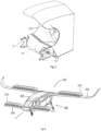
- FIG. 2 an attachment assembly 100 for pivotably connecting a propulsion unit structure 24 and an airframe of a VTOL aircraft is shown, which on its one side in direction Y comprises the rotating hinge joint 10 as shown in Fig. 1 and discussed above. It can be seen that the electric actuator 14 with its stator 14a and rotor 14b connected to the output shaft 16 takes up about half the width of the propulsion unit structure 24 in axial direction Y.
- a pivot assembly 110 is provided, which in a similar manner as the rotating hinge joint 10 allows for a pivoting of the propulsion unit structure 24 with respect to the airframe.
- the pivot assembly 110 comprises a second bracket assembly 112 for attachment to the airframe of the aircraft, a second clevis assembly 122 for attachment to the propulsion unit structure 24 and a pivot pin 116 defining a pivot axis Y for relative rotation between the second bracket assembly 112 and the second clevis assembly 122.
- the pivot pin 116 and the output shaft 16 of the electric actuator 14 of the rotating hinge joint 10 are aligned with respect to their axial directions Y.
- the second clevis assembly 122 is formed similarly to the clevis assembly 22 of the rotating hinge joint 10 with two arms 122a and 122b.
- the rotating hinge joint 10 provides for fixation of the bracket assembly and the clevis assembly with respect to the pivot axis Y of the output shaft 16 of the electric actuator 14, while the pivot assembly 110 provides for a connection of the second bracket assembly 112 and the second clevis assembly 122 in a floating manner with respect to the axial direction Y of the pivot pin 116.
- a suitable bearing 126 is used for supporting the second bracket assembly 112 on the pivot pin 116 in a floating manner.
- Fig. 3 the above-mentioned propulsion unit structure 24 is shown in an isometric view with the attachment assembly 100 integrated therewith. It can be seen that the two bracket assemblies 12 and 112 extend on both sides of the propulsion unit structure 24 with respect to the direction of the axis Y and allow for an attachment of the propulsion unit structure 24 on the airframe of an aircraft, in particular its wings, in a pivotable manner. By pivoting the propulsion unit structure 24 around the axis Y as discussed above, it becomes possible to adjust the direction of the thrust produced by the propulsion motor 210 integrated with the propulsion unit structure 24 as described below with reference to the VTOL aircraft shown in Fig, 4 .
- the aircraft 200 comprises a fuselage 202, a pair of wings 204 and a pair of canard wings 206 positioned in front of the wings 204 with respect to the main horizontal flying direction X of the aircraft 200.
- the fuselage 202, the wings 204 and the canards 206 form the airframe 208 of the aircraft 200.
- a plurality of propulsion unit structures 24 are connected by means of attachment assemblies 100 as shown in Fig. 2 and Fig. 3 .
- each propulsion unit structure 24 is formed as a flap pivotably mounted to the trailing edges of the respective wings 204 or canard wings 206 and carrying at least one propulsion motor 210.
- the propulsion motors 210 may be formed by electrically driven rotors, in particular in ducted fan configurations.
Landscapes
- Engineering & Computer Science (AREA)
- Aviation & Aerospace Engineering (AREA)
- Automation & Control Theory (AREA)
- Pivots And Pivotal Connections (AREA)
Priority Applications (1)
| Application Number | Priority Date | Filing Date | Title |
|---|---|---|---|
| EP22184776.7A EP4306409A1 (de) | 2022-07-13 | 2022-07-13 | Drehgelenkverbindung |
Applications Claiming Priority (1)
| Application Number | Priority Date | Filing Date | Title |
|---|---|---|---|
| EP22184776.7A EP4306409A1 (de) | 2022-07-13 | 2022-07-13 | Drehgelenkverbindung |
Publications (1)
| Publication Number | Publication Date |
|---|---|
| EP4306409A1 true EP4306409A1 (de) | 2024-01-17 |
Family
ID=82594614
Family Applications (1)
| Application Number | Title | Priority Date | Filing Date |
|---|---|---|---|
| EP22184776.7A Pending EP4306409A1 (de) | 2022-07-13 | 2022-07-13 | Drehgelenkverbindung |
Country Status (1)
| Country | Link |
|---|---|
| EP (1) | EP4306409A1 (de) |
Citations (4)
| Publication number | Priority date | Publication date | Assignee | Title |
|---|---|---|---|---|
| US20200086976A1 (en) * | 2016-12-23 | 2020-03-19 | Safran Electronics & Defense | Electromechanical actuator for a movable flight surface |
| EP3789289A1 (de) * | 2019-09-04 | 2021-03-10 | The Boeing Company | Doppelter kurbelwellenverknieungsmechanismus für flap |
| EP3998199A1 (de) * | 2021-02-19 | 2022-05-18 | Lilium eAircraft GmbH | Aktuator für primäre flugsteuerfläche und damit ausgerüstetes ziviles flugzeug |
| EP3998207A1 (de) * | 2021-02-19 | 2022-05-18 | Lilium eAircraft GmbH | Luftfahrzeug |
-
2022
- 2022-07-13 EP EP22184776.7A patent/EP4306409A1/de active Pending
Patent Citations (4)
| Publication number | Priority date | Publication date | Assignee | Title |
|---|---|---|---|---|
| US20200086976A1 (en) * | 2016-12-23 | 2020-03-19 | Safran Electronics & Defense | Electromechanical actuator for a movable flight surface |
| EP3789289A1 (de) * | 2019-09-04 | 2021-03-10 | The Boeing Company | Doppelter kurbelwellenverknieungsmechanismus für flap |
| EP3998199A1 (de) * | 2021-02-19 | 2022-05-18 | Lilium eAircraft GmbH | Aktuator für primäre flugsteuerfläche und damit ausgerüstetes ziviles flugzeug |
| EP3998207A1 (de) * | 2021-02-19 | 2022-05-18 | Lilium eAircraft GmbH | Luftfahrzeug |
Similar Documents
| Publication | Publication Date | Title |
|---|---|---|
| US6802475B2 (en) | Flight surface actuator | |
| EP2099676B1 (de) | Lagerlose rotorblattanordnung für ein hochgeschwindigkeits-drehflügelflugzeug | |
| US6712313B2 (en) | Constant velocity drive rotary-wing aircraft rotor with torque splitting differential | |
| US7264199B2 (en) | Unloaded lift offset rotor system for a helicopter | |
| US4804352A (en) | Link-type rotary coupling | |
| US5226350A (en) | Drive train assembly for a rotor assembly having ducted, coaxial counter-rotating rotors | |
| EP0861775B1 (de) | Koaxiale Übersetzungs-/Zentriernaben-Unteranordnung für Rotoranordnung | |
| US20090092493A1 (en) | Variable pitch rotor blade with double flexible retention elements | |
| JP2768826B2 (ja) | 回転翼型航空機の尾部回転翼のダクトファンおよびピッチ制御装置 | |
| US10220951B2 (en) | Sleeved bolt assemblies for aircraft engine mount assemblies | |
| US9657582B2 (en) | Gimbaled tail rotor hub with spherical elastomeric centrifugal force bearing for blade retention and pitch change articulation | |
| WO2016114851A1 (en) | Single engine, asymmetrical vertical take-off and landing (vtol) aircraft | |
| WO2009140042A1 (en) | Combination spar and trunnion structure for a tilt rotor aircraft | |
| CN110683049B (zh) | 一种用于小型倾转旋翼机的桨毂装置 | |
| US9476312B2 (en) | Swashplateless active blade pitch control with a mechanical delta-3 restraint having an instantaneous blade pitch-flap coupling response | |
| CA2113179C (en) | Ducted tail rotor for rotary wing aircraft providing torque reaction and yaw attitude control | |
| US11691724B2 (en) | Systems and methods for controlling rotor tilt for a vertical take-off and landing aircraft | |
| EP4306409A1 (de) | Drehgelenkverbindung | |
| US6203277B1 (en) | Gyroplane rotor with double-plate hub and external pitch control | |
| WO2002090183A1 (en) | Dual trunnion hub-to-mast assembly | |
| EP3998207A1 (de) | Luftfahrzeug | |
| GB2390344A (en) | Flight surface actuator | |
| IL120577A (en) | From the entire moving series for unmanned aerial vehicles | |
| WO2004045948A1 (en) | Rotary blade |
Legal Events
| Date | Code | Title | Description |
|---|---|---|---|
| PUAI | Public reference made under article 153(3) epc to a published international application that has entered the european phase |
Free format text: ORIGINAL CODE: 0009012 |
|
| STAA | Information on the status of an ep patent application or granted ep patent |
Free format text: STATUS: THE APPLICATION HAS BEEN PUBLISHED |
|
| AK | Designated contracting states |
Kind code of ref document: A1 Designated state(s): AL AT BE BG CH CY CZ DE DK EE ES FI FR GB GR HR HU IE IS IT LI LT LU LV MC MK MT NL NO PL PT RO RS SE SI SK SM TR |