EP4306390A1 - Device for reinforcing a structural element - Google Patents
Device for reinforcing a structural element Download PDFInfo
- Publication number
- EP4306390A1 EP4306390A1 EP22185050.6A EP22185050A EP4306390A1 EP 4306390 A1 EP4306390 A1 EP 4306390A1 EP 22185050 A EP22185050 A EP 22185050A EP 4306390 A1 EP4306390 A1 EP 4306390A1
- Authority
- EP
- European Patent Office
- Prior art keywords
- carrier
- expandable material
- structural element
- outside
- closed surface
- Prior art date
- Legal status (The legal status is an assumption and is not a legal conclusion. Google has not performed a legal analysis and makes no representation as to the accuracy of the status listed.)
- Pending
Links
- 230000003014 reinforcing effect Effects 0.000 title claims abstract description 11
- 239000000463 material Substances 0.000 claims abstract description 50
- 239000000969 carrier Substances 0.000 claims abstract description 12
- 230000008878 coupling Effects 0.000 claims description 15
- 238000010168 coupling process Methods 0.000 claims description 15
- 238000005859 coupling reaction Methods 0.000 claims description 15
- 239000000203 mixture Substances 0.000 claims description 3
- 239000000853 adhesive Substances 0.000 description 4
- 230000001070 adhesive effect Effects 0.000 description 4
- 238000010276 construction Methods 0.000 description 3
- 238000001746 injection moulding Methods 0.000 description 3
- 230000002787 reinforcement Effects 0.000 description 3
- 238000007789 sealing Methods 0.000 description 3
- 229920002430 Fibre-reinforced plastic Polymers 0.000 description 1
- 239000004918 carbon fiber reinforced polymer Substances 0.000 description 1
- 238000005260 corrosion Methods 0.000 description 1
- 230000007797 corrosion Effects 0.000 description 1
- 239000011151 fibre-reinforced plastic Substances 0.000 description 1
- 239000011152 fibreglass Substances 0.000 description 1
- 230000001788 irregular Effects 0.000 description 1
- 230000033001 locomotion Effects 0.000 description 1
- 238000004519 manufacturing process Methods 0.000 description 1
- 239000004033 plastic Substances 0.000 description 1
- 229920003023 plastic Polymers 0.000 description 1
- 239000000243 solution Substances 0.000 description 1
- XLYOFNOQVPJJNP-UHFFFAOYSA-N water Substances O XLYOFNOQVPJJNP-UHFFFAOYSA-N 0.000 description 1
Images


Classifications
-
- B—PERFORMING OPERATIONS; TRANSPORTING
- B62—LAND VEHICLES FOR TRAVELLING OTHERWISE THAN ON RAILS
- B62D—MOTOR VEHICLES; TRAILERS
- B62D25/00—Superstructure or monocoque structure sub-units; Parts or details thereof not otherwise provided for
-
- B—PERFORMING OPERATIONS; TRANSPORTING
- B62—LAND VEHICLES FOR TRAVELLING OTHERWISE THAN ON RAILS
- B62D—MOTOR VEHICLES; TRAILERS
- B62D29/00—Superstructures, understructures, or sub-units thereof, characterised by the material thereof
- B62D29/001—Superstructures, understructures, or sub-units thereof, characterised by the material thereof characterised by combining metal and synthetic material
- B62D29/002—Superstructures, understructures, or sub-units thereof, characterised by the material thereof characterised by combining metal and synthetic material a foamable synthetic material or metal being added in situ
Definitions
- the invention relates to a device for reinforcing a structural element and a system of a reinforced structural element in a motor vehicle.
- components such as bodies and/or frames of means of transport and locomotion, in particular of vehicles on water or on land or of aircraft, have structures with cavities in order to enable lightweight constructions.
- cavities cause a variety of problems. Depending on the type of cavity, it must be sealed to prevent the ingress of moisture and dirt, which can lead to corrosion of the components. It is often desirable to significantly strengthen the cavities and thus the component, but maintain the low weight. It is often also necessary to stabilize the cavities and thus the components in order to reduce noise that would otherwise be transmitted along or through the cavity. Many of these cavities are irregular in shape or narrow in size, making them difficult to properly seal, reinforce and dampen.
- sealing elements are used to seal and/or acoustically insulate cavities, or reinforcing elements (reinforcers) are used to reinforce cavities.
- FIG. 1 A body of an automobile is shown schematically.
- the body 10 has various structures with cavities, such as columns 14 and supports or struts 12.
- Such structural elements 12, 14 with cavities are usually sealed or reinforced with sealing and/or reinforcing elements 16.
- FIG. 2 A known concept for sealing and/or reinforcing such structural elements with cavities in motor vehicles is shown schematically.
- a reinforcing element 16 in a structural element 12, 14 before expansion of an expandable material 13.
- the expandable material 13 is arranged on surfaces of a support element 11, which are arranged in proximity to the structural element 12, 14.
- the carrier element 11 has an M- or W-shaped cross section. This increases the rigidity of the support element 11.
- This carrier element 11 or the reinforcing element 16 is designed in cross section such that it can be produced in a simple manner using the injection molding process.
- adjacent surfaces of the support element 11 are formed with an angle 15 which is slightly larger than 90°.
- a surface of the carrier element 11, which faces an inside of the structural element 12, 14, typically has a checkerboard-like shape.
- the connecting material or the expandable material 13 can only be arranged on surfaces that are arranged in the vicinity of the structural element 12, 14.
- the invention is therefore based on the object of providing an improved device of the type mentioned at the outset, which allows the carrier to be better connected to the structural element.
- the device should be cost-effective and easy to manufacture.
- a device for reinforcing a structural element in a motor vehicle comprising: a first carrier which has an outside with a mostly closed surface and an inside with a surface defined mostly by ribs, at least on the closed surface of the outside a first expandable material is partially arranged; a second carrier which has an outside with a mostly closed surface and an inside with a surface defined mostly by ribs, a second expandable material being at least partially arranged on the closed surface of the outside; wherein the first carrier and the second carrier are connected to each other such that the inner sides of the carriers face each other; and wherein the outsides of the supports are each directed against a wall of the structural element in a state of use, so that the first expandable material and the second expandable material connect the supports to walls of the structural element after expansion.
- This solution has the advantage that a significantly better connection between the carrier and the structural element can be achieved.
- the closed or essentially closed surface of the carrier element offers the possibility of arranging adhesive across the entire surface on both sides of the carrier and thus better connecting the carrier to the structural element. As a result, significantly better reinforcement of cavities can be achieved compared to devices according to the prior art.
- a core idea of the present invention is that by providing two supports that are connected to one another, a new overall support can be provided which offers a lot of bonding surface for adhesive to connect this overall support to the structural element.
- the supports can be put together in a modular manner, so to speak. This means that such a device can be ideally adapted to the respective situation.
- the second expandable material of the second carrier is arranged in an edge region of the outside in such a way that the second expandable material connects both the second carrier to a wall of the structural element and to the inside of the first carrier during expansion
- the second expandable material is arranged on at least 40%, in particular on at least 50%, in particular on at least 60%, in particular on at least 70%, in particular on at least 80% of the edge region of the outside.
- the second expandable material is arranged in the edge region of the outside at a predefined distance and essentially parallel to a rib of the first carrier, so that an elongated connection between the first and second carrier is created by the second expandable material during expansion.
- connection surface of the first carrier can be used in order to achieve a connection between the carriers that is as mechanically resilient as possible.
- the predefined distance is between 0.1 mm and 5 mm, in particular between 0.2 mm and 3 mm, in particular between 0.2 mm and 1 mm.
- the first carrier is larger than the second carrier.
- an area of the inside of the second carrier is between 10% and 80%, in particular between 20% and 70%, in particular between 30% and 60% of an area of the inside of the first carrier.
- the outside of the first carrier and/or the second carrier has a closed surface of at least 70%, in particular at least 75%, in particular at least 80%.
- the inside of the first carrier and/or the second carrier has a surface defined by ribs on at least 70%, in particular on at least 85%, in particular on at least 80%.
- first carrier and the second carrier are connected to one another by at least two mechanical connections, each carrier comprising two coupling elements that can be mechanically connected to the coupling elements of the other carrier.
- the coupling elements are designed as clips and clip openings.
- the coupling elements on the second carrier are arranged in an edge region of the inside, and the coupling elements on the first carrier are arranged on the inside of the first carrier.
- the mechanical connection fixes the first beam and the second beam together for assembly, but does not mechanically connect the beams to one another for an intended load case.
- the first expandable material and the second expandable material have the same composition.
- first expandable material and the second expandable material do not have the same composition, the materials differing in particular by a different expansion rate.
- the first expandable material and/or the second expandable material have an expansion rate of more than 100% and less than 800%, in particular more than 200% and of less than 700%, in particular more than 250% and of less than 600%.
- the expandable material can be used as the expandable material.
- the following commercially available adhesives can be used: SikaReinforcer ® -911, SikaReinforcer ® -940, SikaReinforcer ® -941, SikaReinforcer ® -942, SikaReinforcer ® -943, SikaReinforcer ® -951 and SikaReinforcer ® -955.
- the first expandable material and/or the second expandable material is curable by a temperature of greater than 120°.
- the first carrier and/or the second carrier with the expandable material arranged thereon is produced by a two-component injection molding process.
- the carrier contains plastic, fiber-reinforced plastic (in particular carbon fiber-reinforced plastic or glass fiber-reinforced plastic), or a combination of these materials.
- a system of a reinforced structural element in a motor vehicle comprising: a structural element; a device according to the above description, the device being arranged in the structural element; wherein the expanded material connects the beams to the structural element and the beams to each other.
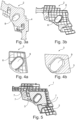
- a first carrier 2 is shown in the 3a and 3b .
- Fig. 3b the inside of the carrier 2 is visible, which has a surface defined mostly by ribs 6.
- the first carrier 2 has a first opening 8, which extends from the outside to the inside.
- FIG. 4a an exemplary second carrier 3 is shown. This is in Fig. 4a the inside of the second carrier 3 is visible, which has a surface defined primarily by ribs 6. In Fig. 4b the outside of the second carrier 3 is visible, which has a mostly closed surface, a second expandable material 5 being arranged on this closed surface.
- the second carrier 2 has a second opening 9, which extends from the outside to the inside.
- Fig. 5 an exemplary device 1 is shown, which includes both the first carrier 2 and the second carrier 3.
- the carriers 2, 3 are connected to one another in such a way that the insides of the carriers 2, 3 face each other.
- first carrier 2 and the second carrier 3 each have two coupling elements 7, which can each be mechanically connected to the coupling elements 7 of the other carrier 2, 3.
- FIG. 6a an exemplary device 1 is again shown.
- FIG. 6b a situation before a connection of the first carrier 2 and the second carrier 3, and the Fig. 6a shows the device 1 with carriers 2, 3 connected to one another.
- the carriers 2, 3 are mechanically connected to one another in that coupling elements 7 each engage in corresponding coupling elements 7 of the other carrier 2, 3.
- the openings 8, 9 of the carriers 2, 3 are designed in such a way that when the carriers 2, 3 are connected, they lie essentially one above the other, so that the Device 1 has an opening which extends through both the first carrier 2 and the second carrier 3.
Abstract
Vorrichtung zur Verstärkung eines Strukturelementes in einem Kraftfahrzeug, umfassend: einen ersten Träger, welcher eine Aussenseite mit einer mehrheitlich geschlossenen Oberfläche hat und eine Innenseite mit einer mehrheitlich durch Rippen definierte Oberfläche hat, wobei auf der geschlossenen Oberfläche der Aussenseite zumindest teilweise ein erstes expandierbares Material angeordnet ist; einen zweiten Träger, welcher eine Aussenseite mit einer mehrheitlich geschlossenen Oberfläche hat und eine Innenseite mit einer mehrheitlich durch Rippen definierte Oberfläche hat, wobei auf der geschlossenen Oberfläche der Aussenseite zumindest teilweise ein zweites expandierbares Material angeordnet ist; wobei der erste Träger und der zweite Träger derart miteinander verbunden sind, dass die Innenseiten der Träger einander zugewandt sind; und wobei die Aussenseiten der Träger in einem Verwendungszustand jeweils gegen eine Wand des Strukturelementes gerichtet sind, sodass das erste expandierbare Material und das zweite expandierbare Material nach einer Expansion die Träger mit Wänden des Strukturelements verbinden.Device for reinforcing a structural element in a motor vehicle, comprising: a first carrier which has an outside with a mostly closed surface and an inside with a surface defined mostly by ribs, a first expandable material being at least partially arranged on the closed surface of the outside is; a second carrier which has an outside with a mostly closed surface and an inside with a surface defined mostly by ribs, a second expandable material being at least partially arranged on the closed surface of the outside; wherein the first carrier and the second carrier are connected to each other such that the inner sides of the carriers face each other; and wherein the outsides of the supports are each directed against a wall of the structural element in a state of use, so that the first expandable material and the second expandable material connect the supports to walls of the structural element after expansion.
Description
Die Erfindung betrifft eine Vorrichtung zur Verstärkung eines Strukturelementes sowie ein System eines verstärkten Strukturelementes in einem Kraftfahrzeug.The invention relates to a device for reinforcing a structural element and a system of a reinforced structural element in a motor vehicle.
Vielfach weisen Bauelemente, wie beispielsweise Karosserien und/oder Rahmen von Transport- und Fortbewegungsmitteln, insbesondere von Fahrzeugen zu Wasser oder zu Land oder von Luftfahrzeugen, Strukturen mit Hohlräumen auf, um leichtgewichtige Konstruktionen zu ermöglichen. Diese Hohlräume verursachen jedoch verschiedenste Probleme. Je nach Art des Hohlraumes muss dieser zum Verhindern des Eindringens von Feuchtigkeit und Verschmutzungen, die zur Korrosion der Bauelemente führen können, abgedichtet werden. Oft ist es auch wünschenswert, die Hohlräume und somit das Bauelement wesentlich zu verstärken, jedoch das geringe Gewicht beizubehalten. Oft ist es auch notwendig, die Hohlräume und somit die Bauelemente zu stabilisieren, um Geräusche, die sonst den Hohlraum entlang oder durch diesen hindurch übertragen werden würden, zu reduzieren. Viele dieser Hohlräume weisen eine unregelmässige Form oder ein enges Ausmass auf, wodurch es erschwert wird, sie richtig abzudichten, zu verstärken und zu dämpfen.In many cases, components such as bodies and/or frames of means of transport and locomotion, in particular of vehicles on water or on land or of aircraft, have structures with cavities in order to enable lightweight constructions. However, these cavities cause a variety of problems. Depending on the type of cavity, it must be sealed to prevent the ingress of moisture and dirt, which can lead to corrosion of the components. It is often desirable to significantly strengthen the cavities and thus the component, but maintain the low weight. It is often also necessary to stabilize the cavities and thus the components in order to reduce noise that would otherwise be transmitted along or through the cavity. Many of these cavities are irregular in shape or narrow in size, making them difficult to properly seal, reinforce and dampen.
Insbesondere im Automobilbau, aber auch im Flugzeug- und Bootsbau, werden deshalb Abdichtungselemente (englisch: baffle) verwendet, um Hohlräume abzudichten und/oder akustisch abzuschotten, oder Verstärkungselemente (englisch: reinforcer) verwendet, um Hohlräume zu verstärken.Particularly in automobile construction, but also in aircraft and boat construction, sealing elements (baffle) are used to seal and/or acoustically insulate cavities, or reinforcing elements (reinforcers) are used to reinforce cavities.
In
In
Dieses Trägerelement 11 bzw. das Verstärkungselement 16 gemäss dem Stand der Technik ist im Querschnitt derart ausgebildet, dass es auf einfache Art und Weise im Spritzgussverfahren hergestellt werden kann. Hierzu sind benachbarte Flächen des Trägerelementes 11 mit einem Winkel 15 ausgebildet, welcher geringfügig grösser als 90° ist. Durch eine solche Ausgestaltung des Querschnittes des Trägerelementes 11 kann das spritzgegossene Trägerelement 11 einfach von der Form der Spritzgussmaschine abgezogen werden.This
Eine Oberfläche des Trägerelementes 11, welche jeweils einer Innenseite des Strukturelementes 12, 14 zugewandt ist, weist typischerweise eine schachbrettartige Form auf. Dabei kann das Verbindungsmaterial bzw. das expandierbare Material 13 jeweils nur auf Flächen angeordnet werden, welche in der Nähe des Strukturelementes 12, 14 angeordnet sind.A surface of the
Nachteilig an solchen Verstärkungselementen 16 ist es, dass das Trägerelement 11 nicht auf optimale Art und Weise mit dem Strukturelement 12, 14 verbunden werden kann, weil hierzu nicht genügend Oberflächen des Trägerelementes 11 zur Verfügung stehen, welche sich in der Nähe des Strukturelementes 12, 14 befinden und sich dadurch zur Anbringung von Verbindungsmaterial 13 eignen.The disadvantage of such reinforcing
Der Erfindung liegt daher die Aufgabe zugrunde, eine verbesserte Vorrichtung der eingangs genannten Art bereitzustellen, welche erlaubt, den Träger besser mit dem Strukturelement zu verbinden. Zudem soll die Vorrichtung kosteneffizient und einfach herzustellen sein.The invention is therefore based on the object of providing an improved device of the type mentioned at the outset, which allows the carrier to be better connected to the structural element. In addition, the device should be cost-effective and easy to manufacture.
Diese Aufgabe wird gelöst durch eine Vorrichtung zur Verstärkung eines Strukturelementes in einem Kraftfahrzeug, umfassend: einen ersten Träger, welcher eine Aussenseite mit einer mehrheitlich geschlossenen Oberfläche hat und eine Innenseite mit einer mehrheitlich durch Rippen definierte Oberfläche hat, wobei auf der geschlossenen Oberfläche der Aussenseite zumindest teilweise ein erstes expandierbares Material angeordnet ist; einen zweiten Träger, welcher eine Aussenseite mit einer mehrheitlich geschlossenen Oberfläche hat und eine Innenseite mit einer mehrheitlich durch Rippen definierte Oberfläche hat, wobei auf der geschlossenen Oberfläche der Aussenseite zumindest teilweise ein zweites expandierbares Material angeordnet ist; wobei der erste Träger und der zweite Träger derart miteinander verbunden sind, dass die Innenseiten der Träger einander zugewandt sind; und wobei die Aussenseiten der Träger in einem Verwendungszustand jeweils gegen eine Wand des Strukturelementes gerichtet sind, sodass das erste expandierbare Material und das zweite expandierbare Material nach einer Expansion die Träger mit Wänden des Strukturelements verbinden.This object is achieved by a device for reinforcing a structural element in a motor vehicle, comprising: a first carrier which has an outside with a mostly closed surface and an inside with a surface defined mostly by ribs, at least on the closed surface of the outside a first expandable material is partially arranged; a second carrier which has an outside with a mostly closed surface and an inside with a surface defined mostly by ribs, a second expandable material being at least partially arranged on the closed surface of the outside; wherein the first carrier and the second carrier are connected to each other such that the inner sides of the carriers face each other; and wherein the outsides of the supports are each directed against a wall of the structural element in a state of use, so that the first expandable material and the second expandable material connect the supports to walls of the structural element after expansion.
Diese Lösung hat den Vorteil, dass dadurch eine markant bessere Verbindung des Trägers mit dem Strukturelement erreicht werden kann. Durch die geschlossene bzw. im Wesentlichen geschlossene Oberfläche des Trägerelementes bietet sich die Möglichkeit, Klebstoff flächendeckend beidseitig des Trägers anzuordnen und somit den Träger mit dem Strukturelement besser zu verbinden. Dadurch können wesentlich bessere Verstärkungen von Hohlräumen erzielt werden im Vergleich zu Vorrichtungen gemäss dem Stand der Technik.This solution has the advantage that a significantly better connection between the carrier and the structural element can be achieved. The closed or essentially closed surface of the carrier element offers the possibility of arranging adhesive across the entire surface on both sides of the carrier and thus better connecting the carrier to the structural element. As a result, significantly better reinforcement of cavities can be achieved compared to devices according to the prior art.
Ein Kerngedanke der vorliegenden Erfindung besteht darin, dass durch das Vorsehen von zwei Trägern, welche miteinander verbunden sind, eine neuer Gesamtträger bereitgestellt werden kann, welcher viel Anbindungsfläche für Klebstoff bietet, um diesen Gesamtträger mit dem Strukturelement zu verbinden. Dabei können die Träger gewissermassen modular zusammengestellt werden. Dadurch kann eine solche Vorrichtung der jeweiligen Situation ideal angepasst werden.A core idea of the present invention is that by providing two supports that are connected to one another, a new overall support can be provided which offers a lot of bonding surface for adhesive to connect this overall support to the structural element. The supports can be put together in a modular manner, so to speak. This means that such a device can be ideally adapted to the respective situation.
In einer beispielhaften Ausführungsform ist das zweite expandierbare Material des zweiten Trägers derart in einem Randbereich der Aussenseite angeordnet, dass das zweite expandierbare Material bei einer Expansion sowohl den zweiten Träger mit einer Wand des Strukturelementes als auch mit der Innenseite des ersten Trägers verbindetIn an exemplary embodiment, the second expandable material of the second carrier is arranged in an edge region of the outside in such a way that the second expandable material connects both the second carrier to a wall of the structural element and to the inside of the first carrier during expansion
Dies hat den Vorteil, dass dadurch eine mechanisch belastbare Verbindung zwischen den Trägern entsteht, nachdem das zweite expandierbare Material expandiert ist.This has the advantage that a mechanically resilient connection is created between the supports after the second expandable material has expanded.
In einer beispielhaften Weiterbildung ist das zweite expandierbare Material auf zumindest 40%, insbesondere auf zumindest 50%, insbesondere auf zumindest 60%, insbesondere auf zumindest 70%, insbesondere auf zumindest 80% des Randbereiches der Aussenseite angeordnet.In an exemplary development, the second expandable material is arranged on at least 40%, in particular on at least 50%, in particular on at least 60%, in particular on at least 70%, in particular on at least 80% of the edge region of the outside.
Dies hat den Vorteil, dass dadurch eine grössere Fläche der beiden Träger miteinander verbunden werden kann, und/oder dass dadurch eine Verbindung auf verschiedenen Seitenflächen des zweiten Trägers mit dem ersten Träger erreicht werden kann. Beides führt zu mechanisch belastbareren Verbindungen zwischen den Trägern.This has the advantage that a larger area of the two carriers can be connected to one another and/or that a connection can be achieved on different side surfaces of the second carrier with the first carrier. Both lead to more mechanically resilient connections between the supports.
In einer beispielhaften Ausführungsform ist das zweite expandierbare Material im Randbereich der Aussenseite in einer vordefinierten Distanz und im Wesentlichen parallel zu einer Rippe des ersten Trägers angeordnet, sodass bei einer Expansion eine längliche Verbindung zwischen erstem und zweitem Träger durch das zweite expandierbare Material entsteht.In an exemplary embodiment, the second expandable material is arranged in the edge region of the outside at a predefined distance and essentially parallel to a rib of the first carrier, so that an elongated connection between the first and second carrier is created by the second expandable material during expansion.
Dies hat den Vorteil, dass dadurch eine geeignete Anbindungsfläche des ersten Trägers verwendet werden kann, um eine möglichst mechanisch belastbare Verbindung zwischen den Träger zu erreichen.This has the advantage that a suitable connection surface of the first carrier can be used in order to achieve a connection between the carriers that is as mechanically resilient as possible.
In einer beispielhaften Weiterbildung beträgt die vordefinierte Distanz zwischen 0.1 mm und 5 mm, insbesondere zwischen 0,2 mm und 3 mm, insbesondere zwischen 0.2 mm und 1 mm.In an exemplary development, the predefined distance is between 0.1 mm and 5 mm, in particular between 0.2 mm and 3 mm, in particular between 0.2 mm and 1 mm.
In einer beispielhaften Ausführungsform ist der erste Träger grösser als der zweite Träger.In an exemplary embodiment, the first carrier is larger than the second carrier.
In einer beispielhaften Ausführungsform beträgt eine Fläche der Innenseite des zweiten Trägers zwischen 10 % und 80 %, insbesondere zwischen 20 % und 70 %, insbesondere zwischen 30 % und 60 % einer Fläche der Innenseite des ersten Trägers.In an exemplary embodiment, an area of the inside of the second carrier is between 10% and 80%, in particular between 20% and 70%, in particular between 30% and 60% of an area of the inside of the first carrier.
In einer beispielhaften Ausführungsform hat die Aussenseite des ersten Trägers und/oder des zweiten Trägers auf zumindest 70 %, insbesondere auf zumindest 75 %, insbesondere auf zumindest 80 % eine geschlossene Oberfläche.In an exemplary embodiment, the outside of the first carrier and/or the second carrier has a closed surface of at least 70%, in particular at least 75%, in particular at least 80%.
Dies hat den Vorteil, dass dadurch eine grössere Fläche zur Anbindung an das Strukturelement zur Verfügung steht, sodass eine bessere Verstärkung erreicht werden kann.This has the advantage that a larger area is available for connection to the structural element, so that better reinforcement can be achieved.
In einer beispielhaften Ausführungsform hat die Innenseite des ersten Trägers und/oder des zweiten Trägers auf zumindest 70 %, insbesondere auf zumindest 85 %, insbesondere auf zumindest 80 % eine durch Rippen definierte Oberfläche.In an exemplary embodiment, the inside of the first carrier and/or the second carrier has a surface defined by ribs on at least 70%, in particular on at least 85%, in particular on at least 80%.
In einer beispielhaften Ausführungsform sind der erste Träger und der zweite Träger durch zumindest zwei mechanische Verbindungen miteinander verbunden, wobei jeder Träger jeweils zwei Kopplungselemente umfasst, welche mechanisch verbindbar sind mit den Kopplungselementen des jeweils anderen Trägers.In an exemplary embodiment, the first carrier and the second carrier are connected to one another by at least two mechanical connections, each carrier comprising two coupling elements that can be mechanically connected to the coupling elements of the other carrier.
Dies hat den Vorteil, dass dadurch auf kostengünstige und zuverlässige Art eine Vorfixierung der Träger zueinander erreicht werden kann.This has the advantage that the carriers can be pre-fixed to one another in a cost-effective and reliable manner.
In einer beispielhaften Ausführungsform sind die Kopplungselemente als Clips und Clipöffnungen ausgebildet.In an exemplary embodiment, the coupling elements are designed as clips and clip openings.
In einer beispielhaften Ausführungsform sind die Kopplungselemente am zweiten Träger in einem Randbereich der Innenseite angeordnet, und wobei die Kopplungselemente am ersten Träger an dessen Innenseite angeordnet sind.In an exemplary embodiment, the coupling elements on the second carrier are arranged in an edge region of the inside, and the coupling elements on the first carrier are arranged on the inside of the first carrier.
In einer beispielhaften Ausführungsform fixiert die mechanische Verbindung den ersten Träger und den zweiten Träger für eine Montage miteinander, aber verbindet die Träger nicht für einen vorgesehenen Lastfall mechanisch miteinander.In an exemplary embodiment, the mechanical connection fixes the first beam and the second beam together for assembly, but does not mechanically connect the beams to one another for an intended load case.
In einer beispielhaften Ausführungsform haben das erste expandierbare Material und das zweite expandierbare Material dieselbe Zusammensetzung.In an exemplary embodiment, the first expandable material and the second expandable material have the same composition.
In einer alternativen Ausführungsform haben das erste expandierbare Material und das zweite expandierbare Material nicht dieselbe Zusammensetzung, wobei sich die Materialien insbesondere durch eine unterschiedliche Expansionsrate unterscheiden.In an alternative embodiment, the first expandable material and the second expandable material do not have the same composition, the materials differing in particular by a different expansion rate.
In einer beispielhaften Ausführungsform haben das erste expandierbare Material und/oder das zweite expandierbare Material eine Expansionsrate von mehr als 100 % und von weniger als 800 %, insbesondere von mehr als 200 % und von weniger als 700 %, insbesondere von mehr als 250 % und von weniger als 600 %.In an exemplary embodiment, the first expandable material and/or the second expandable material have an expansion rate of more than 100% and less than 800%, in particular more than 200% and of less than 700%, in particular more than 250% and of less than 600%.
Als expandierbares Material können grundsätzlich verschiedenartige Materialien verwendet werden. Beispielsweise können folgende im Handel erhältliche Klebstoffe verwendet werden: SikaReinforcer®-911, SikaReinforcer®-940, SikaReinforcer®-941, SikaReinforcer®-942, SikaReinforcer®-943, SikaReinforcer®-951 und SikaReinforcer®-955.In principle, different types of materials can be used as the expandable material. For example, the following commercially available adhesives can be used: SikaReinforcer ® -911, SikaReinforcer ® -940, SikaReinforcer ® -941, SikaReinforcer ® -942, SikaReinforcer ® -943, SikaReinforcer ® -951 and SikaReinforcer ® -955.
In einer beispielhaften Ausführungsform ist das erste expandierbare Material und/oder das zweite expandierbare Material durch eine Temperatur von mehr als 120° härtbar.In an exemplary embodiment, the first expandable material and/or the second expandable material is curable by a temperature of greater than 120°.
In einer beispielhaften Ausführungsform ist der erste Träger und/oder der zweite Träger mit dem jeweils darauf angeordneten expandierbaren Material durch ein Zweikomponenten-Spritzgussverfahren hergestellt.In an exemplary embodiment, the first carrier and/or the second carrier with the expandable material arranged thereon is produced by a two-component injection molding process.
Dies hat den Vorteil, dass dadurch kostengünstige Vorrichtungen hergestellt werden können.This has the advantage that cost-effective devices can be produced.
In einer beispielhaften Ausführungsform enthält der Träger Kunststoff, faserverstärkten Kunststoff (insbesondere karbonfaserverstärkter Kunststoff oder glasfaserverstärkter Kunststoff), oder eine Kombination dieser Materialien.In an exemplary embodiment, the carrier contains plastic, fiber-reinforced plastic (in particular carbon fiber-reinforced plastic or glass fiber-reinforced plastic), or a combination of these materials.
Die eingangs gestellte Aufgabe wird weiterhin gelöst durch ein System eines verstärkten Strukturelementes in einem Kraftfahrzeug, wobei das System umfasst: ein Strukturelement; eine Vorrichtung nach obiger Beschreibung, wobei die Vorrichtung im Strukturelement angeordnet ist; wobei das expandierte Material die Träger mit dem Strukturelement und die Träger untereinander verbindet.The task posed at the outset is further solved by a system of a reinforced structural element in a motor vehicle, the system comprising: a structural element; a device according to the above description, the device being arranged in the structural element; wherein the expanded material connects the beams to the structural element and the beams to each other.
Einzelheiten und Vorteile der Erfindung werden im Folgenden anhand von Ausführungsbeispielen und mit Bezug auf schematische Zeichnungen beschrieben.Details and advantages of the invention are described below using exemplary embodiments and with reference to schematic drawings.
Es zeigen:
- Fig. 1
- beispielhafte Darstellung einer Karosserie;
- Fig. 2
- schematische Darstellung einer beispielhaften Vorrichtung gemäss dem Stand der Technik;
- Fig. 3a und 3b
- schematische Darstellung eines beispielhaften ersten Trägers;
- Fig. 4a und 4b
- schematische Darstellung eines beispielhaften zweiten Trägers;
- Fig. 5
- schematische Darstellung einer beispielhaften Vorrichtung; und
- Fig. 6a und 6b
- schematische Darstellung einer beispielhaften Vorrichtung.
- Fig. 1
- exemplary representation of a body;
- Fig. 2
- schematic representation of an exemplary device according to the prior art;
- 3a and 3b
- schematic representation of an exemplary first carrier;
- 4a and 4b
- schematic representation of an exemplary second carrier;
- Fig. 5
- schematic representation of an exemplary device; and
- 6a and 6b
- schematic representation of an exemplary device.
In den
In diesem Ausführungsbeispiel hat der erste Träger 2 eine erste Öffnung 8, welche sich von der Aussenseite bis zur Innenseite erstreckt.In this exemplary embodiment, the
In den
In diesem Ausführungsbeispiel hat der zweite Träger 2 eine zweite Öffnung 9, welche sich von der Aussenseite bis zur Innenseite erstreckt.In this exemplary embodiment, the
In
In diesem Ausführungsbeispiel hat der erste Träger 2 und der zweite Träger 3 jeweils zwei Kopplungselemente 7, welche jeweils mechanisch mit den Kopplungselementen 7 des anderen Trägers 2, 3 verbindbar sind.In this exemplary embodiment, the
In den
Die Öffnungen 8, 9 der Träger 2, 3 sind dabei so ausgebildet, dass sie in einem verbundenen Zustand der Träger 2, 3 im Wesentlichen übereinander liegen, sodass die Vorrichtung 1 eine Öffnung aufweist, welche sowohl durch den ersten Träger 2 als auch durch den zweiten Träger 3 hindurchreicht.The
- 11
- Vorrichtungcontraption
- 22
- erster Trägerfirst carrier
- 33
- zweiter Trägersecond carrier
- 44
- erstes expandierbares Materialfirst expandable material
- 55
- zweites expandierbares Materialsecond expandable material
- 66
- Ripperib
- 77
- KopplungselementCoupling element
- 88th
- erste Öffnungfirst opening
- 99
- zweite Öffnungsecond opening
- 1010
- Karosseriebody
- 1111
- Trägercarrier
- 1212
- StrukturelementStructural element
- 1313
- Klebstoffadhesive
- 1414
- StrukturelementStructural element
- 1515
- Winkelangle
- 1616
- VerstärkungselementReinforcement element
Claims (15)
Priority Applications (2)
| Application Number | Priority Date | Filing Date | Title |
|---|---|---|---|
| EP22185050.6A EP4306390A1 (en) | 2022-07-14 | 2022-07-14 | Device for reinforcing a structural element |
| PCT/EP2023/068728 WO2024012984A1 (en) | 2022-07-14 | 2023-07-06 | Device for reinforcing a structural element |
Applications Claiming Priority (1)
| Application Number | Priority Date | Filing Date | Title |
|---|---|---|---|
| EP22185050.6A EP4306390A1 (en) | 2022-07-14 | 2022-07-14 | Device for reinforcing a structural element |
Publications (1)
| Publication Number | Publication Date |
|---|---|
| EP4306390A1 true EP4306390A1 (en) | 2024-01-17 |
Family
ID=82608638
Family Applications (1)
| Application Number | Title | Priority Date | Filing Date |
|---|---|---|---|
| EP22185050.6A Pending EP4306390A1 (en) | 2022-07-14 | 2022-07-14 | Device for reinforcing a structural element |
Country Status (2)
| Country | Link |
|---|---|
| EP (1) | EP4306390A1 (en) |
| WO (1) | WO2024012984A1 (en) |
Citations (3)
| Publication number | Priority date | Publication date | Assignee | Title |
|---|---|---|---|---|
| WO2003020574A1 (en) * | 2001-09-05 | 2003-03-13 | L & L Products Inc. | Adjustable reinforced structural assembly and method of use therefor |
| US20130133771A1 (en) * | 2011-11-29 | 2013-05-30 | Zephyros, Inc. | Multi-part insert |
| EP3750681A1 (en) * | 2019-06-11 | 2020-12-16 | Shin Young Co., Ltd. | Reinforcing member |
-
2022
- 2022-07-14 EP EP22185050.6A patent/EP4306390A1/en active Pending
-
2023
- 2023-07-06 WO PCT/EP2023/068728 patent/WO2024012984A1/en unknown
Patent Citations (3)
| Publication number | Priority date | Publication date | Assignee | Title |
|---|---|---|---|---|
| WO2003020574A1 (en) * | 2001-09-05 | 2003-03-13 | L & L Products Inc. | Adjustable reinforced structural assembly and method of use therefor |
| US20130133771A1 (en) * | 2011-11-29 | 2013-05-30 | Zephyros, Inc. | Multi-part insert |
| EP3750681A1 (en) * | 2019-06-11 | 2020-12-16 | Shin Young Co., Ltd. | Reinforcing member |
Also Published As
| Publication number | Publication date |
|---|---|
| WO2024012984A1 (en) | 2024-01-18 |
Similar Documents
| Publication | Publication Date | Title |
|---|---|---|
| EP3486147B1 (en) | Device for reinforcing a structural element | |
| EP3612436B1 (en) | Reinforcing element | |
| EP3486145B1 (en) | System of a reinforced structural element | |
| EP3486144B1 (en) | System of a reinforced structural element of a motor vehicle | |
| DE102011000450A1 (en) | Support structure for producing e.g. A-pillar of vehicle, has expandable adhesive material between structural element and reinforcement element, which surrounds three sides of portion of reinforcement element facing auxiliary frame | |
| EP3486146A1 (en) | Device for reinforcing and sealing a structural element | |
| DE102013014209A1 (en) | Vehicle body with structural component | |
| EP2786922B1 (en) | Body of a motor vehicle made of plastic elements and connection thereof | |
| EP3665068B1 (en) | System of a sealed and reinforced structural element | |
| EP3710341B1 (en) | Device for reinforcing, sealing or damping of a structural element | |
| EP4306390A1 (en) | Device for reinforcing a structural element | |
| EP3710340B1 (en) | Device for reinforcing a structural element | |
| DE102019201415A1 (en) | Body part and method for producing a body part | |
| EP3812121A1 (en) | Vehicle door and production of the same | |
| WO2020043740A1 (en) | System for insulating a structural element | |
| DE102015100968A1 (en) | Method for producing a motor vehicle body in mixed construction | |
| WO2019096618A1 (en) | Device for reinforcing, sealing, or damping a structural element | |
| DE102014011804A1 (en) | Roof module for a passenger car | |
| EP3844051B1 (en) | System for insulation of a structural element | |
| EP3611081B1 (en) | Device for reinforcing, sealing or damping of a structural element | |
| DE102012001647B4 (en) | Method for stiffening a structural component of a motor vehicle | |
| EP2085210A2 (en) | Method to combine at least one of the first plastic elements with at least one of the second plastic elements | |
| DE102016010357B3 (en) | Component, method for manufacturing a component and motor vehicle | |
| DE102015218792A1 (en) | Subframe for a motor vehicle | |
| DE102022210374A1 (en) | Plastic hollow longitudinal beam and method for producing such a plastic hollow longitudinal beam |
Legal Events
| Date | Code | Title | Description |
|---|---|---|---|
| PUAI | Public reference made under article 153(3) epc to a published international application that has entered the european phase |
Free format text: ORIGINAL CODE: 0009012 |
|
| STAA | Information on the status of an ep patent application or granted ep patent |
Free format text: STATUS: THE APPLICATION HAS BEEN PUBLISHED |
|
| AK | Designated contracting states |
Kind code of ref document: A1 Designated state(s): AL AT BE BG CH CY CZ DE DK EE ES FI FR GB GR HR HU IE IS IT LI LT LU LV MC MK MT NL NO PL PT RO RS SE SI SK SM TR |