EP4306380A1 - Recognition device - Google Patents
Recognition device Download PDFInfo
- Publication number
- EP4306380A1 EP4306380A1 EP22766851.4A EP22766851A EP4306380A1 EP 4306380 A1 EP4306380 A1 EP 4306380A1 EP 22766851 A EP22766851 A EP 22766851A EP 4306380 A1 EP4306380 A1 EP 4306380A1
- Authority
- EP
- European Patent Office
- Prior art keywords
- state
- perception
- perception device
- control unit
- operation control
- Prior art date
- Legal status (The legal status is an assumption and is not a legal conclusion. Google has not performed a legal analysis and makes no representation as to the accuracy of the status listed.)
- Pending
Links
Images

Classifications
-
- B—PERFORMING OPERATIONS; TRANSPORTING
- B60—VEHICLES IN GENERAL
- B60W—CONJOINT CONTROL OF VEHICLE SUB-UNITS OF DIFFERENT TYPE OR DIFFERENT FUNCTION; CONTROL SYSTEMS SPECIALLY ADAPTED FOR HYBRID VEHICLES; ROAD VEHICLE DRIVE CONTROL SYSTEMS FOR PURPOSES NOT RELATED TO THE CONTROL OF A PARTICULAR SUB-UNIT
- B60W50/00—Details of control systems for road vehicle drive control not related to the control of a particular sub-unit, e.g. process diagnostic or vehicle driver interfaces
- B60W50/08—Interaction between the driver and the control system
- B60W50/10—Interpretation of driver requests or demands
-
- B—PERFORMING OPERATIONS; TRANSPORTING
- B60—VEHICLES IN GENERAL
- B60R—VEHICLES, VEHICLE FITTINGS, OR VEHICLE PARTS, NOT OTHERWISE PROVIDED FOR
- B60R16/00—Electric or fluid circuits specially adapted for vehicles and not otherwise provided for; Arrangement of elements of electric or fluid circuits specially adapted for vehicles and not otherwise provided for
- B60R16/02—Electric or fluid circuits specially adapted for vehicles and not otherwise provided for; Arrangement of elements of electric or fluid circuits specially adapted for vehicles and not otherwise provided for electric constitutive elements
- B60R16/03—Electric or fluid circuits specially adapted for vehicles and not otherwise provided for; Arrangement of elements of electric or fluid circuits specially adapted for vehicles and not otherwise provided for electric constitutive elements for supply of electrical power to vehicle subsystems or for
-
- B—PERFORMING OPERATIONS; TRANSPORTING
- B60—VEHICLES IN GENERAL
- B60W—CONJOINT CONTROL OF VEHICLE SUB-UNITS OF DIFFERENT TYPE OR DIFFERENT FUNCTION; CONTROL SYSTEMS SPECIALLY ADAPTED FOR HYBRID VEHICLES; ROAD VEHICLE DRIVE CONTROL SYSTEMS FOR PURPOSES NOT RELATED TO THE CONTROL OF A PARTICULAR SUB-UNIT
- B60W40/00—Estimation or calculation of non-directly measurable driving parameters for road vehicle drive control systems not related to the control of a particular sub unit, e.g. by using mathematical models
- B60W40/02—Estimation or calculation of non-directly measurable driving parameters for road vehicle drive control systems not related to the control of a particular sub unit, e.g. by using mathematical models related to ambient conditions
-
- B—PERFORMING OPERATIONS; TRANSPORTING
- B60—VEHICLES IN GENERAL
- B60W—CONJOINT CONTROL OF VEHICLE SUB-UNITS OF DIFFERENT TYPE OR DIFFERENT FUNCTION; CONTROL SYSTEMS SPECIALLY ADAPTED FOR HYBRID VEHICLES; ROAD VEHICLE DRIVE CONTROL SYSTEMS FOR PURPOSES NOT RELATED TO THE CONTROL OF A PARTICULAR SUB-UNIT
- B60W60/00—Drive control systems specially adapted for autonomous road vehicles
- B60W60/001—Planning or execution of driving tasks
- B60W60/0023—Planning or execution of driving tasks in response to energy consumption
-
- G—PHYSICS
- G06—COMPUTING OR CALCULATING; COUNTING
- G06V—IMAGE OR VIDEO RECOGNITION OR UNDERSTANDING
- G06V20/00—Scenes; Scene-specific elements
- G06V20/50—Context or environment of the image
- G06V20/56—Context or environment of the image exterior to a vehicle by using sensors mounted on the vehicle
- G06V20/58—Recognition of moving objects or obstacles, e.g. vehicles or pedestrians; Recognition of traffic objects, e.g. traffic signs, traffic lights or roads
-
- B—PERFORMING OPERATIONS; TRANSPORTING
- B60—VEHICLES IN GENERAL
- B60W—CONJOINT CONTROL OF VEHICLE SUB-UNITS OF DIFFERENT TYPE OR DIFFERENT FUNCTION; CONTROL SYSTEMS SPECIALLY ADAPTED FOR HYBRID VEHICLES; ROAD VEHICLE DRIVE CONTROL SYSTEMS FOR PURPOSES NOT RELATED TO THE CONTROL OF A PARTICULAR SUB-UNIT
- B60W2420/00—Indexing codes relating to the type of sensors based on the principle of their operation
- B60W2420/40—Photo, light or radio wave sensitive means, e.g. infrared sensors
-
- B—PERFORMING OPERATIONS; TRANSPORTING
- B60—VEHICLES IN GENERAL
- B60W—CONJOINT CONTROL OF VEHICLE SUB-UNITS OF DIFFERENT TYPE OR DIFFERENT FUNCTION; CONTROL SYSTEMS SPECIALLY ADAPTED FOR HYBRID VEHICLES; ROAD VEHICLE DRIVE CONTROL SYSTEMS FOR PURPOSES NOT RELATED TO THE CONTROL OF A PARTICULAR SUB-UNIT
- B60W2420/00—Indexing codes relating to the type of sensors based on the principle of their operation
- B60W2420/40—Photo, light or radio wave sensitive means, e.g. infrared sensors
- B60W2420/403—Image sensing, e.g. optical camera
-
- B—PERFORMING OPERATIONS; TRANSPORTING
- B60—VEHICLES IN GENERAL
- B60W—CONJOINT CONTROL OF VEHICLE SUB-UNITS OF DIFFERENT TYPE OR DIFFERENT FUNCTION; CONTROL SYSTEMS SPECIALLY ADAPTED FOR HYBRID VEHICLES; ROAD VEHICLE DRIVE CONTROL SYSTEMS FOR PURPOSES NOT RELATED TO THE CONTROL OF A PARTICULAR SUB-UNIT
- B60W2420/00—Indexing codes relating to the type of sensors based on the principle of their operation
- B60W2420/40—Photo, light or radio wave sensitive means, e.g. infrared sensors
- B60W2420/408—Radar; Laser, e.g. lidar
-
- B—PERFORMING OPERATIONS; TRANSPORTING
- B60—VEHICLES IN GENERAL
- B60Y—INDEXING SCHEME RELATING TO ASPECTS CROSS-CUTTING VEHICLE TECHNOLOGY
- B60Y2400/00—Special features of vehicle units
- B60Y2400/30—Sensors
- B60Y2400/301—Sensors for position or displacement
- B60Y2400/3015—Optical cameras
-
- B—PERFORMING OPERATIONS; TRANSPORTING
- B60—VEHICLES IN GENERAL
- B60Y—INDEXING SCHEME RELATING TO ASPECTS CROSS-CUTTING VEHICLE TECHNOLOGY
- B60Y2400/00—Special features of vehicle units
- B60Y2400/30—Sensors
- B60Y2400/301—Sensors for position or displacement
- B60Y2400/3017—Radars
Definitions
- the present invention relates to a perception device.
- Patent Document 1 Japanese Patent Application Publication No. 2006-260105
- a perception device that is mounted on the moving body and perceives the surroundings of the moving body may take a long time on startup.
- a passenger of the moving body may try to suppress energy consumption of the moving body by stopping the moving body when the moving body is not temporarily used. Accordingly, when the passenger of the moving body starts up the moving body after temporarily stopping the moving body in order to suppress energy consumption of the moving body, the perception device may fail to start up immediately.
- a perception device to solve the above-described problem includes a perception unit configured to perceive surroundings of a moving body based on a detection result of a detection unit, an obtaining unit configured to obtain supply information indicating a supply state of an electric power from a power supply mounted on the moving body to the moving body and instruction information indicating an instruction for an operation to the moving body, and an operation control unit configured to control a state of the perception device based on the supply information and the instruction information.
- the perception device is in a perception state in which the perception device perceives the surroundings, in a stop state in which the perception device stops a process of perceiving the surroundings, or in a standby state in which the perception device stands by until the state of the perception device is transitioned to the perception state.
- the operation control unit keeps the state of the perception device in the perception state without transitioning to the stop state or causes the state of the perception device to transition to the standby state.
- the obtaining unit may obtain information indicating an on-state or an off-state of a switch provided in a key cylinder of the moving body as the instruction information.
- the passenger of the moving body can easily instruct the moving body on the operation.
- the operation control unit may cause the state of the perception device to transition to the stop state.
- the specified condition may include a condition that a specified time has passed since the transitioning to the standby state.
- the operation control unit causes the state of the perception device to transition to the stop state, so that it is possible to suppress energy consumption of the moving body associated with the continuation of the standby state.
- the obtaining unit further obtains detection information indicating the detection result of the detection unit, the specified condition includes a condition that the detection result shows that there is no person around the moving body, after the operation control unit causes the state of the perception device to transition to the standby state, the perception unit perceives the surroundings based on the detection result of the detection unit, and when the perception result shows that there is no person around the moving body, the operation control unit causes the state of the perception device to transition to the stop state.
- the operation control unit causes the state of the perception device to transition to the stop state to suppress energy consumption of the moving body associated with the continuation of the standby state.
- the operation control unit may cause the state of the perception device to transition from the perception state to the standby state.
- the operation control unit causes the state of the perception device to transition to the standby state, so that it is possible to suppress energy consumption of the moving body associated with the continuation of the perception state.
- the perception device shortens a startup time when the moving body is started up after temporarily stopped.
- an industrial vehicle on which a vehicle system illustrated in FIG. 1 is mounted is a vehicle such as a two-wheeler, a three-wheeler, or a four-wheeler, and a driving source of such a vehicle is an internal combustion engine such as a diesel engine or a gasoline engine, an electric motor, or a combination thereof.
- an internal combustion engine such as a diesel engine or a gasoline engine, an electric motor, or a combination thereof.
- the following will describe a case where the industrial vehicle has an internal combustion engine as the driving source.
- the industrial vehicle corresponds to one example of a moving body.
- a vehicle system includes a battery 10, a switch 20, a key cylinder 30, detection units 40, an HMI (Human Machine Interface) 50, a seat sensor 60, a driving operator 70, a perception device 100, a controller 200, a travel driving force output device 300, a braking device 310, and a steering device 320, for example.
- HMI Human Machine Interface
- a seat sensor 60 a driving operator 70
- a perception device 100 a controller 200
- a travel driving force output device 300 a braking device 310
- a steering device 320 for example.
- These devices and pieces of equipment are connected with each other via multiplex communication lines such as CAN (Controller Area Network) communication lines, a serial communication line, a wireless communication network, and the like.
- CAN Controller Area Network
- a secondary storage battery is used as the battery 10 and the battery 10 is charged to store electric power generated by an electric generator connected to the internal combustion engine.
- the electric power stored in the battery 10 is used for startup and operations of various elements in the vehicle system.
- the battery 10 is one example of a power supply mounted on the moving body.
- the switch 20 switches electric connection, for example, between the battery 10 and the various elements in the industrial vehicle. For example, when an operation of the industrial vehicle is completely stopped, the passenger of the industrial vehicle sets the switch 20 in an off-state to electrically disconnect the battery 10 from the industrial vehicle, thereby not allowing the battery 10 to supply the electric power to the industrial vehicle. In addition, when the operation of the industrial vehicle is started up, the passenger of the industrial vehicle sets the switch 20 in an on-state to electrically connect the battery 10 to the industrial vehicle, thereby causing the battery 10 to supply the power to the industrial vehicle. In the subsequent description, information indicating the on-state or the off-state of the switch 20 is also referred to as supply information.
- the on-state or the off-state of the switch 20 correspond to a supply state of the electric power from the battery 10 to the industrial vehicle. Accordingly, supply information indicating that the switch 20 is in the on-state is one example of the supply information indicating that the electric power is supplied from the battery 10 to the industrial vehicle. Further, supply information indicating that the switch 20 is in the off-state is one example of the supply information indicating that the electric power is not supplied from the battery 10 to the industrial vehicle.
- a mechanical key of the industrial vehicle is inserted into the key cylinder 30.
- a switch 31 is provided in the key cylinder 30.
- the switch 31 switches the electric connection between the battery 10 and at least a part of the various elements in the industrial vehicle.
- the passenger of the industrial vehicle rotates the mechanical key inserted in the key cylinder 30 to an off-position when the operation of the industrial vehicle is stopped.
- the passenger of the industrial vehicle rotates the mechanical key inserted in the key cylinder 30 to an on-position when the operation of the industrial vehicle is started up.
- the key cylinder 30 being in an on-state that the switch 31 provided in the key cylinder 30 is in the on-state. It is also referred to as the key cylinder 30 being in an off-state that the switch 31 provided in the key cylinder 30 is in the off-state.
- information indicating the on-state or the off-state of the key cylinder 30 is also referred to as instruction information in the subsequent description.
- setting the key cylinder 30 in the on-state by the passenger of the industrial vehicle instructs the industrial vehicle to start the operation.
- setting the key cylinder 30 in the off-state by the passenger of the industrial vehicle instructs the industrial vehicle to stop the operation.
- the instruction information indicating that the key cylinder 30 is in the on-state is one example of instruction information indicating an instruction for starting the operation of the industrial vehicle.
- the instruction information indicating that the key cylinder 30 is in the off-state is one example of instruction information indicating an instruction for stopping the operation of the industrial vehicle.
- the key cylinder 30 when the key cylinder 30 is set in the off-state, operations of the internal combustion engine and the electric motor of the industrial vehicle are stopped. Accordingly, when the key cylinder 30 is set in the off-state, a part of the various elements in the industrial vehicle that is not stopped by setting the key cylinder 30 in the off-state is operated by the electric power stored in the battery 10.
- the detection units 40 detect an object, and the like around the industrial vehicle.
- the detection units 40 include, for example, a camera 41, a radar 42, and a finder 43.
- the camera 41 is installed at any position at which the camera 41 is capable of capturing the surroundings of the industrial vehicle.
- the camera 41 corresponds to a digital camera including an imaging device such as a CCD (Charge Coupled Device) and a CMOS (Complementary Metal Oxide Semiconductor), and captures the surroundings of the industrial vehicle in specified period.
- the camera 41 captures the surroundings of the industrial vehicle, and outputs image data showing a generated image to the perception device 100.
- the image data is one example of detection information.
- the radar 42 radiates electric waves such as millimeter waves around the industrial vehicle and detects reflected waves reflected from an object present around the industrial vehicle, so that the radar 42 detects at least a position of the object, a distance to the object, and a direction thereto.
- the radar 42 is attached at any point on the industrial vehicle.
- the radar 42 may detect a position and a velocity of the object by using an FM-CW (Frequency Modulated Continuous Wave) method.
- the radar 42 outputs radar information indicating the detection result to the perception device 100.
- the radar information is one example of the detection information.
- the finder 43 is a sensor unit using a LIDAR (Light Detection and Ranging).
- the finder 43 radiates light around the industrial vehicle and measures scattered light.
- the finder 43 detects a distance to the object based on a time from light emission until light reception.
- the radiated light is, for example, pulsed laser light.
- the finder 43 is attached at any point on the industrial vehicle.
- the finder 43 outputs finder information indicating the detection result to the perception device 100.
- the finder information is one example of the detection information.
- the HMI 50 presents various types of information to the passenger of the industrial vehicle, and receives an input by the passenger.
- the HMI 50 includes various types of displays, speakers, buzzers, touch panels, switches, and the like.
- the seat sensor 60 detects whether or not the passenger has got in the industrial vehicle and seated on a seat thereof.
- the seat sensor 60 outputs seating information indicating a detection result to the controller 200.
- the seat sensor 60 is provided in the seat of the industrial vehicle.
- the seat having the seat sensor 60 is, for example, a driver's seat.
- the driving operator 70 includes, for example, an accelerator pedal, a brake pedal, a shift lever, a steering wheel, an odd-shaped steering wheel, a joystick, and other operators.
- a sensor is attached to the driving operator 70 and detects an amount of operation or whether the operation is performed. The detection result of the driving operator 70 is output to the controller 200, or a part or all of the travel driving force output device 300, the braking device 310, and the steering device 320.
- the perception device 100 performs a sensor fusion process on the detected results obtained by a part or all of the camera 41, the radar 42, and the finder 43, so that the perception device 100 perceives the object to obtain a position, a type, and a velocity thereof.
- the perception device 100 outputs the perception result to the controller 200.
- the controller 200 notifies the passenger of the industrial vehicle of the presence of the object around the industrial vehicle based on the perception result obtained from the perception device 100. For example, when the perception result of the perception device 100 indicates that the object is present around the industrial vehicle, the controller 200 outputs a notification sound or a voice sound of a notification message from a speaker of the HMI 50.
- the notification message may include a detailed position and type of the object indicated in the perception result. In detail, the notification message may be a massage, for example, "There is a person in front on your left. Please take care and drive safely.”.
- the controller 200 may output a notification sound from one or more speakers, which are located at a position corresponding to a position of the object present around the industrial vehicle.
- the controller 200 controls the travel driving force output device 300, the braking device 310, and the steering device 320 based on the information input from the driving operator 70.
- the travel driving force output device 300 outputs a travel driving force for the traveling of the industrial vehicle to driving wheels.
- the travel driving force output device 300 includes, for example, a combination of an internal combustion engine, an electric motor, a transmission, and the like and an ECU (Electronic Control Unit) that controls these elements.
- the ECU controls the above-described configuration in accordance with the information input from the controller 200 or the driving operator 70.
- the braking device 310 includes, for example, a brake caliper, a cylinder that transmits hydraulic pressure to the brake caliper, an electric motor that generates the hydraulic pressure in the cylinder, and a brake ECU.
- the brake ECU controls the electric motor according to the information input from the controller 200 or the driving operator 70 so that a brake torque corresponding to a braking operation is output to the respective wheels.
- the braking device 310 may include a mechanism that transmits hydraulic pressure generated by operating the brake pedal in the driving operator 70, to the cylinder through a master cylinder as a backup.
- the braking device 310 is not limited to the above-described configuration, and may be an electronically controlled hydraulic braking device that controls an actuator according to the information input from the controller 200, which transmits the hydraulic pressure of the master cylinder to the cylinder.
- the steering device 320 includes, for example, a steering ECU and an electric motor.
- the electric motor applies a force to a rack and pinion mechanism to change a direction of steered wheels.
- the steering ECU drives the electric motor according to the information input from the controller 200 or the information input from the driving operator 70 to change the direction of the steered wheels.
- the switch 20 switches the electrical connection between the battery 10 and the various elements in the industrial vehicle
- the key cylinder 30 switches the electrical connection between the battery 10 and at least a part of the various elements in the industrial vehicle.
- the battery 10 is connected to the perception device 100 via the switch 20.
- the key cylinder 30 is not connected between the perception device 100 and the battery 10. Accordingly, when the switch 20 is set in the on-state, electric power is supplied to the perception device 100 from the battery 10 regardless of the state of the key cylinder 30.
- the perception device 100 includes, for example, a control unit 120 and a memory 130.
- the control unit 120 is, for example, a hardware processor such as a CPU (Central Processing Unit) that executes programs (software).
- a part or all of these elements may be formed of a hardware (a circuit unit: including circuitry) such as an LSI (Large Scale Integration), an ASIC (Application Specific Integrated Circuit), an FPGA (Field-Programmable Gate Array), or a GPU (Graphics Processing Unit), or a combination of the software and the hardware.
- LSI Large Scale Integration
- ASIC Application Specific Integrated Circuit
- FPGA Field-Programmable Gate Array
- GPU Graphics Processing Unit
- the memory 130 is formed of, for example, a memory (a memory including non-transitory storage medium) such as an HDD (Hard Disk Drive) or a flash memory, or a detachable memory such as a DVD or a CD-ROM.
- a memory a memory including non-transitory storage medium
- HDD Hard Disk Drive
- flash memory or a detachable memory such as a DVD or a CD-ROM.
- the programs serving as the control unit 120 are stored in the memory 130.
- the control unit 120 includes, for example, an obtaining unit 121, a perception unit 122, and an operation control unit 123.
- the obtaining unit 121 obtains the supply information from the switch 20 and the instruction information from the key cylinder 30.
- the obtaining unit 121 also obtains the seating information from the seat sensor 60.
- the obtaining unit 121 also obtains the information indicating the detection results from the detection units 40. Specifically, the obtaining unit 121 obtains the image data from the camera 41, the radar information from the radar 42, and the finder information from the finder 43.
- the perception unit 122 perceives surroundings of the industrial vehicle based on the information indicating detection results of the detection units 40 obtained by the obtaining unit 121. More specifically, the perception unit 122 performs the sensor fusion process on the detection results from a part or all of the camera 41, the radar 42, and the finder 43, so that the perception unit 122 perceives the object to obtain a position, a type, a velocity, and the like of an object present around the industrial vehicle.
- the operation control unit 123 controls a state of the perception device 100 based on the information obtained by the obtaining unit 121.
- the operation control unit 123 causes a state of the perception device 100 to transition to any one of a perception state, a stop state, and a standby state, for example.
- the perception state is a state in which the perception device 100 perceives the surroundings of the industrial vehicle.
- the stop state is a state in which the perception device 100 stops a process of perceiving the surroundings of the industrial vehicles.
- the standby state is a state in which the perception device 100 stands by until the state of the perception device 100 is transitioned to the perception state.
- the state of the perception device 100 may take a long time that the state of the perception device 100 is transitioned from the stop state to the perception state after controlled to be set in the stop state.
- a time required for the transitioning from the standby state to the perception state is shorter than that required for the transitioning from the stop state to the perception state.
- the power of the perception device 100 is turned off.
- the standby state is, for example, a power saving state in which an amount of electric power consumed by the perception device 100 is smaller than that in the perception state.
- the perception device 100 does not perform a process of perceiving the surroundings of the industrial vehicle in the standby state.
- Step S100 the switch 20 is in the off-state.
- the vehicle system stops until the switch 20 is set in the on-state (Step S100).
- the operation control unit 123 determines whether or not the key cylinder 30 is in the on-state based on the instruction information obtained by the obtaining unit 121 (Step S102).
- the operation control unit 123 causes the state of the perception device 100 to transition to the stop state, and then, proceeds to Step S102 (Step S104).
- the operation control unit 123 starts the transition from the stop state to the perception state when the instruction information indicates that the key cylinder 30 is in the on-state (Step S106). As described above, it may take a long time that the state of the perception device 100 is transitioned from the stop state to the perception state.
- the operation control unit 123 determines whether or not the key cylinder 30 is controlled to be set in the off-state in a specified time required for the transitioning from the stop state to the perception state, based on the instruction information obtained by the obtaining unit 121 (Step S108).
- the operation control unit 123 determines that the key cylinder 30 is controlled to be set in the off-state in the specified time required for the transitioning from the stop state to the perception state, the operation control unit 123 stops the process of the transitioning from the stop state to the perception state, and proceeds to Step S102.
- the operation control unit 123 determines that the key cylinder 30 is not controlled to be set in the off-state within the specified time required for the transitioning from the stop state to the perception state, the operation control unit 123 does not stop the process of the transitioning but causes the state of the perception device 100 to transition to the perception state (Step S110).
- the perception unit 122 perceives the surroundings of the industrial vehicle based on the information indicating the detection results of detection units 40 obtained by the obtaining unit 121. Further, a notification lamp, which is not illustrated, is provided on the industrial vehicle.
- the controller 200 may supply electric power to the notification lamp and emit light to the passenger.
- the notification lamp notifies an operator that the state of the perception device 100 is set in the perception state.
- the notification lamp is preferably provided on a pillar of a headguard in view of visibility of the passenger.
- the notification lamp may be provided on a housing of the camera 41 or various display devices of the HMI 50.
- the operation control unit 123 determines whether or not the key cylinder 30 is in the off-state based on the instruction information obtained by the obtaining unit 121 (Step S112). The operation control unit 123 proceeds to Step S110, and keeps the state of the perception device 100 in the perception state until the key cylinder 30 is determined to be in the off-state when the perception device 100 is in the perception state.
- the operation control unit 123 determines that the key cylinder 30 is in the off-state based on the instruction information obtained by the obtaining unit 121
- the operation control unit 123 causes the state of the perception device 100 to transition to the standby state (Step S114).
- the controller 200 may shut off the power to the notification lamp and turn off the notification lamp when the state of the perception device 100 is set in the standby state.
- the operation control unit 123 determines whether or not a specified condition is satisfied (Step S116).
- the specified condition includes, for example, two conditions of a first condition and a second condition.
- the first condition is that the specified time has passed since the transitioning to the standby state.
- the specified time may be changed in correspondence with a remaining electric power of the battery 10, may be determined in advance based on an electrical power consumed when the perception device 100 operates in the standby state, or may be determined based on a value input to the HMI 50 by the passenger of the industrial vehicle.
- the operation control unit 123 determines, at all times or at each time interval shorter than the specified time, whether the time that has passed since the state of the perception device 100 is transitioned to the standby state in Step S114 is equal to or longer than the specified time.
- the second condition is that the detection results of the detection units 40 show that there is no person around the industrial vehicle.
- the operation control unit 123 causes the state of the perception device 100 to transition to the standby state in Step S114, the obtaining unit 121 obtains detection information from the detection units 40 at all times or at each time interval shorter than the specified time. Every time the obtaining unit 121 obtains detection information, the operation control unit 123 causes the perception unit 122 to temporarily perceive the surroundings of the industrial vehicle based on the obtained detection information. The operation control unit 123 determines whether or not the perception result by the perception unit 122 shows that there is no person around the industrial vehicle.
- Step S118 When the operation control unit 123 determines that the specified condition is satisfied after causing the state of the perception device 100 to transition to the standby state, the operation control unit 123 causes the state of the perception device 100 to transition to the stop state, and proceeds to Step S102 (Step S118). In the present embodiment, when the operation control unit 123 determines that the first condition or the second condition is satisfied, it is considered that the specified condition is satisfied, so that the operation control unit 123 proceeds to Step S118.
- the specified condition is determined to be satisfied.
- the specified condition is also determined to be satisfied.
- the specified condition is also determined to be satisfied.
- Step S120 the operation control unit 123 determines whether the key cylinder 30 is set in the on-state.
- the operation control unit 123 processes to Step S114 until the operation control unit 123 determines that the key cylinder 30 is set in the on-state, and keeps the state of the perception device 100 in the standby state.
- Step S122 the operation control unit 123 starts the transition from the standby state to the perception state.
- a time required from the start of the transitioning from the standby state to the perception state in Step S122 to the completion of the transitioning is shorter than the time required from the start of the transitioning from the stop state to the perception state in Step S106 to the completion of the transitioning.
- the operation control unit 123 determines whether the key cylinder 30 is controlled to be set in the off-state in the specified time required for the transitioning from the standby state to the perception state, based on the instruction information obtained by the obtaining unit 121 (Step S124). When the operation control unit 123 determines that the key cylinder 30 is controlled to be set in the off-state within the specified time required for the transitioning from the standby state to the perception state, the operation control unit 123 proceeds to Step S114, and keeps the state of the perception device 100 in the standby state.
- Step S110 causes the state of the perception device 100 to transition to the standby state.
- the operation control unit 123 causes the state of the perception device 100 to transition to the standby state.
- the operation control unit 123 suppresses energy consumption of the industrial vehicle associated with the continuation of the perception state.
- the case where the operation of the industrial vehicle is stopped again while the perception device 100 starts up in the shortened startup time corresponds to a case where the passenger of the industrial vehicle operates the key cylinder 30 by mistake, for example.
- the operation control unit 123 causes the state of the perception device 100 to transition to the standby state in Step S114, but the present invention is not limited to this aspect.
- the operation control unit 123 may keep the state of the perception device 100 in the perception state.
- the operation control unit 123 immediately operates the industrial vehicle without starting up the perception device 100 again.
- the operation control unit 123 instead of the process in which the operation control unit 123 causes the state of the perception device 100 to transition to the standby state, the operation control unit 123 keeps the state of the perception device 100 in the perception state in Step S114.
- the process of the start of the transitioning from the standby state to the perception state in Step S122 is omitted.
- the configuration of the vehicle system illustrated in FIG. 1 is merely one example, and a part of the elements may be omitted or another element may be added to the vehicle system.
- the detection units 40 may have elements other than the above-described elements.
- the detection units 40 may include, for example, an acceleration sensor, a velocity sensor, and the like that do not require the sensor fusion process by the perception device 100.
- the controller 200 may obtain the detection result of the acceleration sensor or the velocity sensor not via the perception device 100.
- the detection units 40 may include a part of the above-described elements.
- the obtaining unit 121 may obtain the instruction information from a device other than the key cylinder 30.
- the obtaining unit 121 may obtain the seating information as the instruction information.
- the passenger of the industrial vehicle gets out of the industrial vehicle and leaves the seat, which corresponds to instructing the industrial vehicle to stop the operation.
- the passenger of the industrial vehicle gets in the industrial vehicle and sits on the seat, which corresponds to instructing the industrial vehicle to start the operation.
- the obtaining unit 121 may also obtain information indicating whether or not the parking brake is operated, as the instruction information.
- the passenger of the industrial vehicle sets the parking brake in an operation state, which corresponds to instructing the industrial vehicle to stop the operation.
- the passenger of the industrial vehicle sets the parking brake in a non-operation state, which corresponds to instruct the industrial vehicle to start the operation.
- the perception result of the perception device 100 may be used for causing the industrial vehicle to travel autonomously in addition to the notification to the passenger of the industrial vehicle.
- the controller 200 generates a target track along which the industrial vehicle will travel autonomously.
- the autonomously travelling includes travelling without a driver's operation.
- the target track includes, for example, a velocity element.
- the target track may be expressed as arrangement of track points to be reached by the industrial vehicle in order.
- the track points are points to be reached by the industrial vehicle, and arranged along the generated track at each specified traveling distance.
- a target velocity and a target acceleration are generated as a part of the target track at each specified sampling time.
- the specified traveling distance corresponds to a distance of about a few meters [m], for example.
- the specified sampling time corresponds to a time of about zero point a few seconds [sec], for example.
- the track points may be positions to be reached by the industrial vehicle at the sampling time at each specified sampling time.
- the information of the target velocity and the target acceleration is expressed by intervals between the track points.
- the controller 200 controls the travel driving force output device 300, the braking device 310, and the steering device 320 so that the industrial vehicle passes along the generated target track on time.
- the operation control unit 123 may determine that the predetermined condition is satisfied when both the first condition and the second condition are satisfied.
- the first condition and the second condition as the specified condition are just examples, and are not limited thereto.
- the vehicle system need not include the HMI 50.
- the vehicle system need not include the seat sensor 60.
- the operation control unit 123 may determine whether or not a passenger is in the industrial vehicle, based on other information instead of or in addition to the seating information obtained from the seat sensor 60.
- the operation control unit 123 may determine whether or not a passenger is in the industrial vehicle, based on a detection result of a grip sensor provided on a steering wheel of the industrial vehicle, for example.
- the operation control unit 123 may determine whether or not a passenger is in the industrial vehicle, based on images generated by a vehicle interior camera, which is provided in the vehicle interior of the industrial vehicle and captures the vehicle interior.
- the present invention is not limited to this aspect. Even when the key cylinder 30 is set in the off-state, the internal combustion engine and the electric motor of the industrial vehicle may continue operating in the perception state or in the standby state.
- the internal combustion engine of the industrial vehicle may be controlled to be set in an idling state in the standby state.
Landscapes
- Engineering & Computer Science (AREA)
- Mechanical Engineering (AREA)
- Automation & Control Theory (AREA)
- Transportation (AREA)
- Physics & Mathematics (AREA)
- Human Computer Interaction (AREA)
- Mathematical Physics (AREA)
- General Physics & Mathematics (AREA)
- Multimedia (AREA)
- Theoretical Computer Science (AREA)
- Forklifts And Lifting Vehicles (AREA)
- Electric Propulsion And Braking For Vehicles (AREA)
- Control Of Position, Course, Altitude, Or Attitude Of Moving Bodies (AREA)
- Control Of Driving Devices And Active Controlling Of Vehicle (AREA)
- Lighting Device Outwards From Vehicle And Optical Signal (AREA)
- Remote Sensing (AREA)
- Radar, Positioning & Navigation (AREA)
- Aviation & Aerospace Engineering (AREA)
- Navigation (AREA)
- Holo Graphy (AREA)
- Air Bags (AREA)
- Acyclic And Carbocyclic Compounds In Medicinal Compositions (AREA)
- User Interface Of Digital Computer (AREA)
Abstract
Description
- The present invention relates to a perception device.
- In a moving body that travels autonomously, there is described a technique for perceiving surroundings of the moving body (For example, see Patent Document 1).
- Patent Document 1:
Japanese Patent Application Publication No. 2006-260105 - Here, a perception device that is mounted on the moving body and perceives the surroundings of the moving body may take a long time on startup. In addition, a passenger of the moving body may try to suppress energy consumption of the moving body by stopping the moving body when the moving body is not temporarily used. Accordingly, when the passenger of the moving body starts up the moving body after temporarily stopping the moving body in order to suppress energy consumption of the moving body, the perception device may fail to start up immediately.
- A perception device to solve the above-described problem includes a perception unit configured to perceive surroundings of a moving body based on a detection result of a detection unit, an obtaining unit configured to obtain supply information indicating a supply state of an electric power from a power supply mounted on the moving body to the moving body and instruction information indicating an instruction for an operation to the moving body, and an operation control unit configured to control a state of the perception device based on the supply information and the instruction information. The perception device is in a perception state in which the perception device perceives the surroundings, in a stop state in which the perception device stops a process of perceiving the surroundings, or in a standby state in which the perception device stands by until the state of the perception device is transitioned to the perception state. When the instruction information obtained in the perception state indicates the instruction for stopping the operation of the moving body, the operation control unit keeps the state of the perception device in the perception state without transitioning to the stop state or causes the state of the perception device to transition to the standby state.
- With this configuration, when the moving body is started up after the passenger of the moving body temporarily stops the moving body, a startup time of the perception device is shortened due to the perception device.
- According to the above-described perception device the obtaining unit may obtain information indicating an on-state or an off-state of a switch provided in a key cylinder of the moving body as the instruction information.
- With this configuration, due to the perception device, the passenger of the moving body can easily instruct the moving body on the operation.
- According to the above-described perception device, after the operation control unit keeps the state of the perception device in the perception state or causes the state of the perception device to transition to the standby state, when a specified condition is satisfied, the operation control unit may cause the state of the perception device to transition to the stop state.
- With this configuration, when the specified condition is satisfied, it is possible that the operation control unit suppresses energy consumption of the moving body.
- According to the above-described perception device, the specified condition may include a condition that a specified time has passed since the transitioning to the standby state.
- With this configuration, when the specified time has passed since the transition to the standby state, the operation control unit causes the state of the perception device to transition to the stop state, so that it is possible to suppress energy consumption of the moving body associated with the continuation of the standby state.
- According to the above-described perception device, the obtaining unit further obtains detection information indicating the detection result of the detection unit, the specified condition includes a condition that the detection result shows that there is no person around the moving body, after the operation control unit causes the state of the perception device to transition to the standby state, the perception unit perceives the surroundings based on the detection result of the detection unit, and when the perception result shows that there is no person around the moving body, the operation control unit causes the state of the perception device to transition to the stop state.
- With this configuration, when the detection result shows that there is no person around the moving body, it is possible that the operation control unit causes the state of the perception device to transition to the stop state to suppress energy consumption of the moving body associated with the continuation of the standby state.
- According to the above-described perception device, in a case where the instruction information indicates the instruction for stopping the operation of the moving body when the operation control unit causes the state of the perception device to transition from the standby state to the perception state, the operation control unit may cause the state of the perception device to transition from the perception state to the standby state.
- With this configuration, after the state of the perception device is transitioned from the standby state to the perception state, in a case where the operation of the moving body is stopped again while the perception device starts up in a shortened startup time, the operation control unit causes the state of the perception device to transition to the standby state, so that it is possible to suppress energy consumption of the moving body associated with the continuation of the perception state.
- According to the present invention, the perception device shortens a startup time when the moving body is started up after temporarily stopped.
-
-
FIG. 1 is a view illustrating an example of a configuration of a vehicle system having a perception device according to an embodiment. -
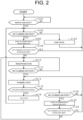
FIG. 2 is a flowchart showing an example of an operation of the perception device. - The following will describe an embodiment of a perception device according to the present invention with reference to the drawings.
- One example of an industrial vehicle on which a vehicle system illustrated in
FIG. 1 is mounted is a vehicle such as a two-wheeler, a three-wheeler, or a four-wheeler, and a driving source of such a vehicle is an internal combustion engine such as a diesel engine or a gasoline engine, an electric motor, or a combination thereof. The following will describe a case where the industrial vehicle has an internal combustion engine as the driving source. The industrial vehicle corresponds to one example of a moving body. - A vehicle system includes a
battery 10, aswitch 20, a key cylinder 30,detection units 40, an HMI (Human Machine Interface) 50, aseat sensor 60, adriving operator 70, aperception device 100, acontroller 200, a travel drivingforce output device 300, abraking device 310, and asteering device 320, for example. These devices and pieces of equipment are connected with each other via multiplex communication lines such as CAN (Controller Area Network) communication lines, a serial communication line, a wireless communication network, and the like. - For example, a secondary storage battery is used as the
battery 10 and thebattery 10 is charged to store electric power generated by an electric generator connected to the internal combustion engine. The electric power stored in thebattery 10 is used for startup and operations of various elements in the vehicle system. Thebattery 10 is one example of a power supply mounted on the moving body. - The
switch 20 switches electric connection, for example, between thebattery 10 and the various elements in the industrial vehicle. For example, when an operation of the industrial vehicle is completely stopped, the passenger of the industrial vehicle sets theswitch 20 in an off-state to electrically disconnect thebattery 10 from the industrial vehicle, thereby not allowing thebattery 10 to supply the electric power to the industrial vehicle. In addition, when the operation of the industrial vehicle is started up, the passenger of the industrial vehicle sets theswitch 20 in an on-state to electrically connect thebattery 10 to the industrial vehicle, thereby causing thebattery 10 to supply the power to the industrial vehicle. In the subsequent description, information indicating the on-state or the off-state of theswitch 20 is also referred to as supply information. Here, the on-state or the off-state of theswitch 20 correspond to a supply state of the electric power from thebattery 10 to the industrial vehicle. Accordingly, supply information indicating that theswitch 20 is in the on-state is one example of the supply information indicating that the electric power is supplied from thebattery 10 to the industrial vehicle. Further, supply information indicating that theswitch 20 is in the off-state is one example of the supply information indicating that the electric power is not supplied from thebattery 10 to the industrial vehicle. - A mechanical key of the industrial vehicle is inserted into the key cylinder 30. A
switch 31 is provided in the key cylinder 30. When the mechanical key inserted in the key cylinder 30 is rotated, theswitch 31 switches the electric connection between thebattery 10 and at least a part of the various elements in the industrial vehicle. For example, the passenger of the industrial vehicle rotates the mechanical key inserted in the key cylinder 30 to an off-position when the operation of the industrial vehicle is stopped. On the other hand, the passenger of the industrial vehicle rotates the mechanical key inserted in the key cylinder 30 to an on-position when the operation of the industrial vehicle is started up. - In the subsequent description, it is also referred to as the key cylinder 30 being in an on-state that the
switch 31 provided in the key cylinder 30 is in the on-state. It is also referred to as the key cylinder 30 being in an off-state that theswitch 31 provided in the key cylinder 30 is in the off-state. In addition, information indicating the on-state or the off-state of the key cylinder 30 is also referred to as instruction information in the subsequent description. Here, setting the key cylinder 30 in the on-state by the passenger of the industrial vehicle instructs the industrial vehicle to start the operation. On the other hand, setting the key cylinder 30 in the off-state by the passenger of the industrial vehicle instructs the industrial vehicle to stop the operation. Accordingly, the instruction information indicating that the key cylinder 30 is in the on-state is one example of instruction information indicating an instruction for starting the operation of the industrial vehicle. The instruction information indicating that the key cylinder 30 is in the off-state is one example of instruction information indicating an instruction for stopping the operation of the industrial vehicle. - In the present embodiment, when the key cylinder 30 is set in the off-state, operations of the internal combustion engine and the electric motor of the industrial vehicle are stopped. Accordingly, when the key cylinder 30 is set in the off-state, a part of the various elements in the industrial vehicle that is not stopped by setting the key cylinder 30 in the off-state is operated by the electric power stored in the
battery 10. - The
detection units 40 detect an object, and the like around the industrial vehicle. Thedetection units 40 include, for example, acamera 41, aradar 42, and afinder 43. - The
camera 41 is installed at any position at which thecamera 41 is capable of capturing the surroundings of the industrial vehicle. Thecamera 41 corresponds to a digital camera including an imaging device such as a CCD (Charge Coupled Device) and a CMOS (Complementary Metal Oxide Semiconductor), and captures the surroundings of the industrial vehicle in specified period. Thecamera 41 captures the surroundings of the industrial vehicle, and outputs image data showing a generated image to theperception device 100. The image data is one example of detection information. - The
radar 42 radiates electric waves such as millimeter waves around the industrial vehicle and detects reflected waves reflected from an object present around the industrial vehicle, so that theradar 42 detects at least a position of the object, a distance to the object, and a direction thereto. Theradar 42 is attached at any point on the industrial vehicle. Theradar 42 may detect a position and a velocity of the object by using an FM-CW (Frequency Modulated Continuous Wave) method. Theradar 42 outputs radar information indicating the detection result to theperception device 100. The radar information is one example of the detection information. - The
finder 43 is a sensor unit using a LIDAR (Light Detection and Ranging). Thefinder 43 radiates light around the industrial vehicle and measures scattered light. Thefinder 43 detects a distance to the object based on a time from light emission until light reception. The radiated light is, for example, pulsed laser light. Thefinder 43 is attached at any point on the industrial vehicle. Thefinder 43 outputs finder information indicating the detection result to theperception device 100. The finder information is one example of the detection information. - The
HMI 50 presents various types of information to the passenger of the industrial vehicle, and receives an input by the passenger. TheHMI 50 includes various types of displays, speakers, buzzers, touch panels, switches, and the like. - The
seat sensor 60 detects whether or not the passenger has got in the industrial vehicle and seated on a seat thereof. Theseat sensor 60 outputs seating information indicating a detection result to thecontroller 200. Theseat sensor 60 is provided in the seat of the industrial vehicle. The seat having theseat sensor 60 is, for example, a driver's seat. - The driving
operator 70 includes, for example, an accelerator pedal, a brake pedal, a shift lever, a steering wheel, an odd-shaped steering wheel, a joystick, and other operators. A sensor is attached to thedriving operator 70 and detects an amount of operation or whether the operation is performed. The detection result of the drivingoperator 70 is output to thecontroller 200, or a part or all of the travel drivingforce output device 300, thebraking device 310, and thesteering device 320. - The
perception device 100 performs a sensor fusion process on the detected results obtained by a part or all of thecamera 41, theradar 42, and thefinder 43, so that theperception device 100 perceives the object to obtain a position, a type, and a velocity thereof. Theperception device 100 outputs the perception result to thecontroller 200. - The
controller 200 notifies the passenger of the industrial vehicle of the presence of the object around the industrial vehicle based on the perception result obtained from theperception device 100. For example, when the perception result of theperception device 100 indicates that the object is present around the industrial vehicle, thecontroller 200 outputs a notification sound or a voice sound of a notification message from a speaker of theHMI 50. The notification message may include a detailed position and type of the object indicated in the perception result. In detail, the notification message may be a massage, for example, "There is a person in front on your left. Please take care and drive safely.". In addition, when theHMI 50 includes a plurality of speakers that are each installed on all sides in a vehicle interior, thecontroller 200 may output a notification sound from one or more speakers, which are located at a position corresponding to a position of the object present around the industrial vehicle. - The
controller 200 controls the travel drivingforce output device 300, thebraking device 310, and thesteering device 320 based on the information input from the drivingoperator 70. - The travel driving
force output device 300 outputs a travel driving force for the traveling of the industrial vehicle to driving wheels. The travel drivingforce output device 300 includes, for example, a combination of an internal combustion engine, an electric motor, a transmission, and the like and an ECU (Electronic Control Unit) that controls these elements. The ECU controls the above-described configuration in accordance with the information input from thecontroller 200 or the drivingoperator 70. - The
braking device 310 includes, for example, a brake caliper, a cylinder that transmits hydraulic pressure to the brake caliper, an electric motor that generates the hydraulic pressure in the cylinder, and a brake ECU. The brake ECU controls the electric motor according to the information input from thecontroller 200 or the drivingoperator 70 so that a brake torque corresponding to a braking operation is output to the respective wheels. Thebraking device 310 may include a mechanism that transmits hydraulic pressure generated by operating the brake pedal in thedriving operator 70, to the cylinder through a master cylinder as a backup. Thebraking device 310 is not limited to the above-described configuration, and may be an electronically controlled hydraulic braking device that controls an actuator according to the information input from thecontroller 200, which transmits the hydraulic pressure of the master cylinder to the cylinder. - The
steering device 320 includes, for example, a steering ECU and an electric motor. For example, the electric motor applies a force to a rack and pinion mechanism to change a direction of steered wheels. The steering ECU drives the electric motor according to the information input from thecontroller 200 or the information input from the drivingoperator 70 to change the direction of the steered wheels. - As described above, the
switch 20 switches the electrical connection between thebattery 10 and the various elements in the industrial vehicle, and the key cylinder 30 switches the electrical connection between thebattery 10 and at least a part of the various elements in the industrial vehicle. In the present embodiment, thebattery 10 is connected to theperception device 100 via theswitch 20. The key cylinder 30 is not connected between theperception device 100 and thebattery 10. Accordingly, when theswitch 20 is set in the on-state, electric power is supplied to theperception device 100 from thebattery 10 regardless of the state of the key cylinder 30. - The following will describe a detail of the
perception device 100. Theperception device 100 includes, for example, acontrol unit 120 and amemory 130. Thecontrol unit 120 is, for example, a hardware processor such as a CPU (Central Processing Unit) that executes programs (software). A part or all of these elements may be formed of a hardware (a circuit unit: including circuitry) such as an LSI (Large Scale Integration), an ASIC (Application Specific Integrated Circuit), an FPGA (Field-Programmable Gate Array), or a GPU (Graphics Processing Unit), or a combination of the software and the hardware. - The
memory 130 is formed of, for example, a memory (a memory including non-transitory storage medium) such as an HDD (Hard Disk Drive) or a flash memory, or a detachable memory such as a DVD or a CD-ROM. The programs serving as thecontrol unit 120 are stored in thememory 130. - The
control unit 120 includes, for example, an obtainingunit 121, aperception unit 122, and anoperation control unit 123. The obtainingunit 121 obtains the supply information from theswitch 20 and the instruction information from the key cylinder 30. The obtainingunit 121 also obtains the seating information from theseat sensor 60. The obtainingunit 121 also obtains the information indicating the detection results from thedetection units 40. Specifically, the obtainingunit 121 obtains the image data from thecamera 41, the radar information from theradar 42, and the finder information from thefinder 43. - The
perception unit 122 perceives surroundings of the industrial vehicle based on the information indicating detection results of thedetection units 40 obtained by the obtainingunit 121. More specifically, theperception unit 122 performs the sensor fusion process on the detection results from a part or all of thecamera 41, theradar 42, and thefinder 43, so that theperception unit 122 perceives the object to obtain a position, a type, a velocity, and the like of an object present around the industrial vehicle. - The
operation control unit 123 controls a state of theperception device 100 based on the information obtained by the obtainingunit 121. Theoperation control unit 123 causes a state of theperception device 100 to transition to any one of a perception state, a stop state, and a standby state, for example. The perception state is a state in which theperception device 100 perceives the surroundings of the industrial vehicle. The stop state is a state in which theperception device 100 stops a process of perceiving the surroundings of the industrial vehicles. The standby state is a state in which theperception device 100 stands by until the state of theperception device 100 is transitioned to the perception state. - Here, it may take a long time that the state of the
perception device 100 is transitioned from the stop state to the perception state after controlled to be set in the stop state. A time required for the transitioning from the standby state to the perception state is shorter than that required for the transitioning from the stop state to the perception state. In the stop state, for example, the power of theperception device 100 is turned off. The standby state is, for example, a power saving state in which an amount of electric power consumed by theperception device 100 is smaller than that in the perception state. In the subsequent description, it is assumed that theperception device 100 does not perform a process of perceiving the surroundings of the industrial vehicle in the standby state. - The following will describe a detail of a process in which the
operation control unit 123 causes the state of theperception device 100 to transition, referring toFIG. 2 . In the start of a present flowchart, theswitch 20 is in the off-state. Firstly, the vehicle system stops until theswitch 20 is set in the on-state (Step S100). When theswitch 20 is controlled to be set in the on-state and the operation of the vehicle system is started, theoperation control unit 123 determines whether or not the key cylinder 30 is in the on-state based on the instruction information obtained by the obtaining unit 121 (Step S102). When the instruction information indicates that the key cylinder 30 is in the off-state, theoperation control unit 123 causes the state of theperception device 100 to transition to the stop state, and then, proceeds to Step S102 (Step S104). - The
operation control unit 123 starts the transition from the stop state to the perception state when the instruction information indicates that the key cylinder 30 is in the on-state (Step S106). As described above, it may take a long time that the state of theperception device 100 is transitioned from the stop state to the perception state. Theoperation control unit 123 determines whether or not the key cylinder 30 is controlled to be set in the off-state in a specified time required for the transitioning from the stop state to the perception state, based on the instruction information obtained by the obtaining unit 121 (Step S108). When theoperation control unit 123 determines that the key cylinder 30 is controlled to be set in the off-state in the specified time required for the transitioning from the stop state to the perception state, theoperation control unit 123 stops the process of the transitioning from the stop state to the perception state, and proceeds to Step S102. - When the
operation control unit 123 determines that the key cylinder 30 is not controlled to be set in the off-state within the specified time required for the transitioning from the stop state to the perception state, theoperation control unit 123 does not stop the process of the transitioning but causes the state of theperception device 100 to transition to the perception state (Step S110). When theperception device 100 is in the perception state, theperception unit 122 perceives the surroundings of the industrial vehicle based on the information indicating the detection results ofdetection units 40 obtained by the obtainingunit 121. Further, a notification lamp, which is not illustrated, is provided on the industrial vehicle. When the state of theperception device 100 is set in the perception state, thecontroller 200 may supply electric power to the notification lamp and emit light to the passenger. In this way, the notification lamp notifies an operator that the state of theperception device 100 is set in the perception state. When the industrial vehicle is a forklift, the notification lamp is preferably provided on a pillar of a headguard in view of visibility of the passenger. However, the notification lamp may be provided on a housing of thecamera 41 or various display devices of theHMI 50. - When the
perception device 100 is in the perception state, theoperation control unit 123 determines whether or not the key cylinder 30 is in the off-state based on the instruction information obtained by the obtaining unit 121 (Step S112). Theoperation control unit 123 proceeds to Step S110, and keeps the state of theperception device 100 in the perception state until the key cylinder 30 is determined to be in the off-state when theperception device 100 is in the perception state. When theoperation control unit 123 determines that the key cylinder 30 is in the off-state based on the instruction information obtained by the obtainingunit 121, theoperation control unit 123 causes the state of theperception device 100 to transition to the standby state (Step S114). Thecontroller 200 may shut off the power to the notification lamp and turn off the notification lamp when the state of theperception device 100 is set in the standby state. - After the
operation control unit 123 causes the state of theperception device 100 to transition to the standby state, theoperation control unit 123 determines whether or not a specified condition is satisfied (Step S116). The specified condition includes, for example, two conditions of a first condition and a second condition. - The first condition is that the specified time has passed since the transitioning to the standby state. For example, the specified time may be changed in correspondence with a remaining electric power of the
battery 10, may be determined in advance based on an electrical power consumed when theperception device 100 operates in the standby state, or may be determined based on a value input to theHMI 50 by the passenger of the industrial vehicle. For example, theoperation control unit 123 determines, at all times or at each time interval shorter than the specified time, whether the time that has passed since the state of theperception device 100 is transitioned to the standby state in Step S114 is equal to or longer than the specified time. - The second condition is that the detection results of the
detection units 40 show that there is no person around the industrial vehicle. For example, after theoperation control unit 123 causes the state of theperception device 100 to transition to the standby state in Step S114, the obtainingunit 121 obtains detection information from thedetection units 40 at all times or at each time interval shorter than the specified time. Every time the obtainingunit 121 obtains detection information, theoperation control unit 123 causes theperception unit 122 to temporarily perceive the surroundings of the industrial vehicle based on the obtained detection information. Theoperation control unit 123 determines whether or not the perception result by theperception unit 122 shows that there is no person around the industrial vehicle. - When the
operation control unit 123 determines that the specified condition is satisfied after causing the state of theperception device 100 to transition to the standby state, theoperation control unit 123 causes the state of theperception device 100 to transition to the stop state, and proceeds to Step S102 (Step S118). In the present embodiment, when theoperation control unit 123 determines that the first condition or the second condition is satisfied, it is considered that the specified condition is satisfied, so that theoperation control unit 123 proceeds to Step S118. - Specifically, when the
operation control unit 123 determines that the time that has passed since causing the state of theperception device 100 to transition to the standby state in Step S114 is equal to or longer than the specified time, the specified condition is determined to be satisfied. When theoperation control unit 123 determines that the obtained seating information indicates that there is no passenger in the industrial vehicle, the specified condition is also determined to be satisfied. In addition, when theoperation control unit 123 determines that the perception result of theperception unit 122 shows that the there is no person around the industrial vehicle, the specified condition is also determined to be satisfied. - When the
operation control unit 123 determines that the specified condition is not satisfied, theoperation control unit 123 determines whether the key cylinder 30 is set in the on-state (Step S120). Theoperation control unit 123 processes to Step S114 until theoperation control unit 123 determines that the key cylinder 30 is set in the on-state, and keeps the state of theperception device 100 in the standby state. When theoperation control unit 123 determines that the key cylinder 30 is set in the on-state, theoperation control unit 123 starts the transition from the standby state to the perception state (Step S122). A time required from the start of the transitioning from the standby state to the perception state in Step S122 to the completion of the transitioning is shorter than the time required from the start of the transitioning from the stop state to the perception state in Step S106 to the completion of the transitioning. - The
operation control unit 123 determines whether the key cylinder 30 is controlled to be set in the off-state in the specified time required for the transitioning from the standby state to the perception state, based on the instruction information obtained by the obtaining unit 121 (Step S124). When theoperation control unit 123 determines that the key cylinder 30 is controlled to be set in the off-state within the specified time required for the transitioning from the standby state to the perception state, theoperation control unit 123 proceeds to Step S114, and keeps the state of theperception device 100 in the standby state. On the other hand, when theoperation control unit 123 determines that the key cylinder 30 is not controlled to be set in the off-state within the specified time required for the transitioning from the standby state to the perception state, theoperation control unit 123 proceeds to Step S110, and causes the state of theperception device 100 to transition to the standby state. - The following will describe effects of the present embodiment described above.
- (1) When the instruction information obtained while the state of the
perception device 100 is in the perception state indicates an instruction for stopping the operation of the industrial vehicle, theoperation control unit 123 does not cause the state of theperception device 100 to transition to the stop state but causes the state of theperception device 100 to transition to the standby state.
Here, the passenger of the industrial vehicle may frequently stop the operation of the industrial vehicle at the time of loading or unloading loads on or from the industrial vehicle, or the like. With this configuration, when the industrial vehicle is started up after the passenger of the industrial vehicle temporarily stops the industrial vehicle, a startup time of theperception device 100 is shortened due to theperception device 100. - (2) The obtaining
unit 121 obtains the information indicating the on-state or the off-state of theswitch 31 provided in the key cylinder 30 as the instruction information.
With this configuration, due to theperception device 100, the passenger of the industrial vehicle can easily instruct the industrial vehicle on the operation by a simple measure such as the key cylinder 30. - (3) After the
operation control unit 123 causes the state of theperception device 100 to transition to the standby state, when the specified condition is satisfied, theoperation control unit 123 causes the state of theperception device 100 to transition to the stop state.
With this configuration, when the specified condition is satisfied, theoperation control unit 123 causes the state of theperception device 100 to transition to the stop state, so that it is possible to suppress energy consumption of the industrial vehicle associated with a continuation of the standby state. - (4) The specified condition includes the condition that the specified time has passed since the transitioning to the standby state. After the
operation control unit 123 causes the state of theperception device 100 to transition to the standby state, when the specified time passes, theoperation control unit 123 causes the state of theperception device 100 to transition to the stop state.
With this configuration, when the specified time has passed since the transitioning to the standby state, theoperation control unit 123 causes the state of theperception device 100 to transition to the stop state, so that it is possible to suppress energy consumption of the industrial vehicle associated with the continuation of the standby state. - (5) The obtaining
unit 121 further obtains detection information indicating the detection results of thedetection units 40. The specified condition includes the condition that the detection results show that there is no person around the industrial vehicle. After theoperation control unit 123 causes the state of theperception device 100 to transition to the standby state, when the detection results show that there is no person around the industrial vehicle, theoperation control unit 123 causes the state of theperception device 100 to transition to the stop state.
With this configuration, when there is no person around the industrial vehicle, the passenger is regarded as one who does not use the industrial vehicle, so that theoperation control unit 123 causes the state of theperception device 100 to transition to the stop state. As a result, it is possible that theoperation control unit 123 suppresses the energy consumption of the industrial vehicle associated with the continuation of the standby state. - (6) After the
operation control unit 123 causes the state of theperception device 100 to transition to the standby state, when the specified condition is not satisfied, theoperation control unit 123 keeps the state of theperception device 100 in the current state.
With this configuration, when the passenger of the industrial vehicle starts up the industrial vehicle after temporarily stopping the industrial vehicle, the startup time of theperception device 100 is shortened due to theoperation control unit 123. - (7) In a case where the instruction information indicates the instruction for stopping the operation of the industrial vehicle when the
operation control unit 123 causes the state of theperception device 100 to transition from the standby state to the perception state, theoperation control unit 123 causes the state of theperception device 100 to transition from the perception state to the standby state. - With this configuration, after the state of the
perception device 100 is transitioned from the standby state to the perception state, in a case where the operation of the industrial vehicle is stopped again while theperception device 100 starts up in the shortened startup time, theoperation control unit 123 causes the state of theperception device 100 to transition to the standby state. With this configuration, it is possible that theoperation control unit 123 suppresses energy consumption of the industrial vehicle associated with the continuation of the perception state. The case where the operation of the industrial vehicle is stopped again while theperception device 100 starts up in the shortened startup time corresponds to a case where the passenger of the industrial vehicle operates the key cylinder 30 by mistake, for example. - In the above description, the
operation control unit 123 causes the state of theperception device 100 to transition to the standby state in Step S114, but the present invention is not limited to this aspect. For example, when theoperation control unit 123 determines that the key cylinder 30 is in the off-state while theperception device 100 is in the perception state, theoperation control unit 123 may keep the state of theperception device 100 in the perception state. As a result, when the passenger of the industrial vehicle starts up the industrial vehicle after temporarily stopping the industrial vehicle, it is possible that theoperation control unit 123 immediately operates the industrial vehicle without starting up theperception device 100 again. In this case, instead of the process in which theoperation control unit 123 causes the state of theperception device 100 to transition to the standby state, theoperation control unit 123 keeps the state of theperception device 100 in the perception state in Step S114. Here, the process of the start of the transitioning from the standby state to the perception state in Step S122 is omitted. - The above-described embodiments may be modified as follows. The above-described embodiments and the following modifications may be combined with each other as long as there is no technical contradiction with each other.
- The configuration of the vehicle system illustrated in
FIG. 1 is merely one example, and a part of the elements may be omitted or another element may be added to the vehicle system. - The
detection units 40 may have elements other than the above-described elements. Thedetection units 40 may include, for example, an acceleration sensor, a velocity sensor, and the like that do not require the sensor fusion process by theperception device 100. In this case, thecontroller 200 may obtain the detection result of the acceleration sensor or the velocity sensor not via theperception device 100. In addition, thedetection units 40 may include a part of the above-described elements. - The obtaining
unit 121 may obtain the instruction information from a device other than the key cylinder 30. For example, the obtainingunit 121 may obtain the seating information as the instruction information. The passenger of the industrial vehicle gets out of the industrial vehicle and leaves the seat, which corresponds to instructing the industrial vehicle to stop the operation. The passenger of the industrial vehicle gets in the industrial vehicle and sits on the seat, which corresponds to instructing the industrial vehicle to start the operation. The obtainingunit 121 may also obtain information indicating whether or not the parking brake is operated, as the instruction information. The passenger of the industrial vehicle sets the parking brake in an operation state, which corresponds to instructing the industrial vehicle to stop the operation. The passenger of the industrial vehicle sets the parking brake in a non-operation state, which corresponds to instruct the industrial vehicle to start the operation. - The perception result of the
perception device 100 may be used for causing the industrial vehicle to travel autonomously in addition to the notification to the passenger of the industrial vehicle. In this case, thecontroller 200 generates a target track along which the industrial vehicle will travel autonomously. The autonomously travelling includes travelling without a driver's operation. The target track includes, for example, a velocity element. The target track may be expressed as arrangement of track points to be reached by the industrial vehicle in order. The track points are points to be reached by the industrial vehicle, and arranged along the generated track at each specified traveling distance. In addition to the track points, a target velocity and a target acceleration are generated as a part of the target track at each specified sampling time. The specified traveling distance corresponds to a distance of about a few meters [m], for example. The specified sampling time corresponds to a time of about zero point a few seconds [sec], for example. The track points may be positions to be reached by the industrial vehicle at the sampling time at each specified sampling time. In this case, the information of the target velocity and the target acceleration is expressed by intervals between the track points. Thecontroller 200 controls the travel drivingforce output device 300, thebraking device 310, and thesteering device 320 so that the industrial vehicle passes along the generated target track on time. - The
operation control unit 123 may determine that the predetermined condition is satisfied when both the first condition and the second condition are satisfied. The first condition and the second condition as the specified condition are just examples, and are not limited thereto. - In a case where the specified time in the first condition is not determined by the input to the
HMI 50 by the passenger, the vehicle system need not include theHMI 50. - In a case in which the second condition is not used for the determination of the specified condition, the vehicle system need not include the
seat sensor 60. - The
operation control unit 123 may determine whether or not a passenger is in the industrial vehicle, based on other information instead of or in addition to the seating information obtained from theseat sensor 60. Theoperation control unit 123 may determine whether or not a passenger is in the industrial vehicle, based on a detection result of a grip sensor provided on a steering wheel of the industrial vehicle, for example. Alternatively, theoperation control unit 123 may determine whether or not a passenger is in the industrial vehicle, based on images generated by a vehicle interior camera, which is provided in the vehicle interior of the industrial vehicle and captures the vehicle interior. - A case where the operations of the internal combustion engine and the electric motor of the industrial vehicle are stopped when the key cylinder 30 is set in the off-state is described in the present embodiment. However, the present invention is not limited to this aspect. Even when the key cylinder 30 is set in the off-state, the internal combustion engine and the electric motor of the industrial vehicle may continue operating in the perception state or in the standby state. The internal combustion engine of the industrial vehicle may be controlled to be set in an idling state in the standby state.
-
- M industrial vehicle
- 1 vehicle system
- 10 battery
- 20 switch
- 30 key cylinder
- 40 detection unit
- 41 camera
- 42 radar
- 43 finder
- 50 HMI
- 60 seat sensor
- 70 driving operator
- 100 perception device
- 120 control unit
- 121 obtaining unit
- 122 perception unit
- 123 operation control unit
- 130 memory
- 200 controller
- 300 travel driving force output device
- 310 braking device
- 320 steering device
Claims (6)
- A perception device comprising:a perception unit configured to perceive surroundings of a moving body based on a detection result of a detection unit;an obtaining unit configured to obtain supply information indicating a supply state of an electric power from a power supply mounted on the moving body to the moving body and instruction information indicating an instruction for an operation to the moving body; andan operation control unit configured to control a state of the perception device based on the supply information and the instruction information, whereinthe perception device is in a perception state in which the perception device perceives the surroundings, in a stop state in which the perception device stops a process of perceiving the surroundings, or in a standby state in which the perception device stands by until the state of the perception device is transitioned to the perception state, andwhen the instruction information obtained in the perception state indicates the instruction for stopping the operation of the moving body, the operation control unit keeps the state of the perception device in the perception state without transitioning to the stop state or causes the state of the perception device to transition to the standby state.
- The perception device according to claim 1, wherein
the obtaining unit obtains information indicating an on-state or an off-state of a switch provided in a key cylinder of the moving body as the instruction information. - The perception device according to claim 1 or 2, wherein
after the operation control unit keeps the state of the perception device in the perception state or causes the state of the perception device to transition to the standby state, when a specified condition is satisfied, the operation control unit causes the state of the perception device to transition to the stop state. - The perception device according to claim 3, wherein
the specified condition includes a condition that a specified time has passed since the transitioning to the standby state. - The perception device according to claim 3 or 4, whereinthe obtaining unit further obtains detection information indicating the detection result of the detection unit,the specified condition includes a condition that the detection result shows that there is no person around the moving body,after the operation control unit causes the state of the perception device to transition to the standby state, the perception unit perceives the surroundings based on the detection result of the detection unit, andwhen the perception result shows that there is no person around the moving body, the operation control unit causes the state of the perception device 100 to transition to the stop state.
- The perception device according to any one of claims 1 to 5, wherein
in a case where the instruction information indicates the instruction for stopping the operation of the moving body when the operation control unit causes the state of the perception device to transition from the standby state to the perception state, the operation control unit causes the state of the perception device to transition from the perception state to the standby state.
Applications Claiming Priority (2)
| Application Number | Priority Date | Filing Date | Title |
|---|---|---|---|
| JP2021038454A JP7489005B2 (en) | 2021-03-10 | 2021-03-10 | Recognition device |
| PCT/JP2022/007711 WO2022190892A1 (en) | 2021-03-10 | 2022-02-24 | Recognition device |
Publications (2)
| Publication Number | Publication Date |
|---|---|
| EP4306380A1 true EP4306380A1 (en) | 2024-01-17 |
| EP4306380A4 EP4306380A4 (en) | 2024-08-14 |
Family
ID=83227827
Family Applications (1)
| Application Number | Title | Priority Date | Filing Date |
|---|---|---|---|
| EP22766851.4A Pending EP4306380A4 (en) | 2021-03-10 | 2022-02-24 | RECOGNITION DEVICE |
Country Status (8)
| Country | Link |
|---|---|
| US (1) | US12503069B2 (en) |
| EP (1) | EP4306380A4 (en) |
| JP (1) | JP7489005B2 (en) |
| KR (1) | KR20230133933A (en) |
| CN (1) | CN116940494A (en) |
| AU (1) | AU2022233894B2 (en) |
| CA (1) | CA3210409A1 (en) |
| WO (1) | WO2022190892A1 (en) |
Families Citing this family (1)
| Publication number | Priority date | Publication date | Assignee | Title |
|---|---|---|---|---|
| JPWO2024048433A1 (en) | 2022-08-31 | 2024-03-07 |
Family Cites Families (10)
| Publication number | Priority date | Publication date | Assignee | Title |
|---|---|---|---|---|
| JP4241651B2 (en) | 2005-03-16 | 2009-03-18 | パナソニック電工株式会社 | Mobile device |
| JP2011023921A (en) | 2009-07-15 | 2011-02-03 | Nec Corp | Mobile terminal apparatus |
| JP4987100B2 (en) * | 2010-05-11 | 2012-07-25 | 有限会社 麻里府商事 | Automatic imaging apparatus and method |
| JP2011143925A (en) * | 2011-04-15 | 2011-07-28 | Sanyo Electric Co Ltd | On-vehicle camera system |
| JP6235456B2 (en) * | 2014-12-25 | 2017-11-22 | 株式会社東芝 | In-vehicle electronic devices |
| JP6725377B2 (en) * | 2016-09-15 | 2020-07-15 | 株式会社小糸製作所 | Camera monitor system |
| US10911725B2 (en) * | 2017-03-09 | 2021-02-02 | Digital Ally, Inc. | System for automatically triggering a recording |
| JP2018149951A (en) * | 2017-03-14 | 2018-09-27 | 三菱電機株式会社 | Vehicle control apparatus and vehicle control method |
| KR20180120463A (en) | 2017-04-27 | 2018-11-06 | 주식회사 알오씨오토시스템 | Idle Stop Control Apparatus and Method using 48V Starter Generator |
| JP7325085B2 (en) * | 2019-03-25 | 2023-08-14 | 株式会社ユピテル | Recording device, vehicle information processing device, etc. |
-
2021
- 2021-03-10 JP JP2021038454A patent/JP7489005B2/en active Active
-
2022
- 2022-02-24 WO PCT/JP2022/007711 patent/WO2022190892A1/en not_active Ceased
- 2022-02-24 KR KR1020237029904A patent/KR20230133933A/en not_active Ceased
- 2022-02-24 AU AU2022233894A patent/AU2022233894B2/en active Active
- 2022-02-24 US US18/279,722 patent/US12503069B2/en active Active
- 2022-02-24 CN CN202280019400.XA patent/CN116940494A/en active Pending
- 2022-02-24 CA CA3210409A patent/CA3210409A1/en active Pending
- 2022-02-24 EP EP22766851.4A patent/EP4306380A4/en active Pending
Also Published As
| Publication number | Publication date |
|---|---|
| AU2022233894B2 (en) | 2024-11-21 |
| WO2022190892A1 (en) | 2022-09-15 |
| EP4306380A4 (en) | 2024-08-14 |
| AU2022233894A1 (en) | 2023-08-17 |
| CA3210409A1 (en) | 2022-09-15 |
| CN116940494A (en) | 2023-10-24 |
| JP7489005B2 (en) | 2024-05-23 |
| KR20230133933A (en) | 2023-09-19 |
| US12503069B2 (en) | 2025-12-23 |
| JP2022138527A (en) | 2022-09-26 |
| US20240308451A1 (en) | 2024-09-19 |
Similar Documents
| Publication | Publication Date | Title |
|---|---|---|
| US11180139B2 (en) | Driving support device and driving support method | |
| EP3135565B1 (en) | Parking assistance device | |
| US11548501B2 (en) | Parking assist system | |
| CN112644468B (en) | Parking assistance device, parking assistance method, and non-transitory storage medium | |
| JP7009436B2 (en) | Vehicle display device and parking support system | |
| US12377855B2 (en) | Vehicle control device, vehicle control method, and storage medium | |
| US20210179079A1 (en) | Parking assist system | |
| EP4306380A1 (en) | Recognition device | |
| JP7448394B2 (en) | parking assistance system | |
| US11370448B2 (en) | Vehicle control device and method based on user-requested driving force | |
| US20200255016A1 (en) | Vehicle control device, vehicle, and vehicle control method | |
| JP7489415B2 (en) | Driving assistance device, driving assistance method, and program | |
| JP6998359B2 (en) | Parking support system | |
| JP7429141B2 (en) | parking assistance system | |
| US11292484B2 (en) | Vehicle control device, vehicle, and vehicle control method | |
| JP2023051394A (en) | parking assist device | |
| US20240174225A1 (en) | Vehicle control device, vehicle control method, and storage medium | |
| US12491898B2 (en) | Vehicle control device, vehicle control method, and storage medium | |
| US20240109550A1 (en) | Control device, control method, and storage medium | |
| JP7041118B2 (en) | Parking support system | |
| US11097734B2 (en) | Vehicle control device, vehicle, and vehicle control method | |
| US11104342B2 (en) | Vehicle control device, vehicle, and vehicle control method | |
| US12091009B2 (en) | Vehicle control device and vehicle control method | |
| US20260061988A1 (en) | Parking exit assist device and parking exit assist method for vehicle | |
| US12397788B2 (en) | Vehicle control device, vehicle control method, and storage medium |
Legal Events
| Date | Code | Title | Description |
|---|---|---|---|
| STAA | Information on the status of an ep patent application or granted ep patent |
Free format text: STATUS: THE INTERNATIONAL PUBLICATION HAS BEEN MADE |
|
| PUAI | Public reference made under article 153(3) epc to a published international application that has entered the european phase |
Free format text: ORIGINAL CODE: 0009012 |
|
| STAA | Information on the status of an ep patent application or granted ep patent |
Free format text: STATUS: REQUEST FOR EXAMINATION WAS MADE |
|
| 17P | Request for examination filed |
Effective date: 20230810 |
|
| AK | Designated contracting states |
Kind code of ref document: A1 Designated state(s): AL AT BE BG CH CY CZ DE DK EE ES FI FR GB GR HR HU IE IS IT LI LT LU LV MC MK MT NL NO PL PT RO RS SE SI SK SM TR |
|
| DAV | Request for validation of the european patent (deleted) | ||
| DAX | Request for extension of the european patent (deleted) | ||
| REG | Reference to a national code |
Ref country code: DE Ref legal event code: R079 Free format text: PREVIOUS MAIN CLASS: B60W0050100000 Ipc: B60R0016030000 |
|
| P01 | Opt-out of the competence of the unified patent court (upc) registered |
Free format text: CASE NUMBER: APP_38616/2024 Effective date: 20240627 |
|
| A4 | Supplementary search report drawn up and despatched |
Effective date: 20240715 |
|
| RIC1 | Information provided on ipc code assigned before grant |
Ipc: B60W 40/02 20060101ALI20240709BHEP Ipc: B60W 50/10 20120101ALI20240709BHEP Ipc: B60R 16/03 20060101AFI20240709BHEP |