EP4306365A1 - Sound absorbing material, and vehicle member - Google Patents
Sound absorbing material, and vehicle member Download PDFInfo
- Publication number
- EP4306365A1 EP4306365A1 EP21937001.2A EP21937001A EP4306365A1 EP 4306365 A1 EP4306365 A1 EP 4306365A1 EP 21937001 A EP21937001 A EP 21937001A EP 4306365 A1 EP4306365 A1 EP 4306365A1
- Authority
- EP
- European Patent Office
- Prior art keywords
- sound absorbing
- layer
- absorbing material
- substrate
- resin
- Prior art date
- Legal status (The legal status is an assumption and is not a legal conclusion. Google has not performed a legal analysis and makes no representation as to the accuracy of the status listed.)
- Granted
Links
Images

Classifications
-
- B—PERFORMING OPERATIONS; TRANSPORTING
- B60—VEHICLES IN GENERAL
- B60R—VEHICLES, VEHICLE FITTINGS, OR VEHICLE PARTS, NOT OTHERWISE PROVIDED FOR
- B60R13/00—Elements for body-finishing, identifying, or decorating; Arrangements or adaptations for advertising purposes
- B60R13/08—Insulating elements, e.g. for sound insulation
-
- B—PERFORMING OPERATIONS; TRANSPORTING
- B32—LAYERED PRODUCTS
- B32B—LAYERED PRODUCTS, i.e. PRODUCTS BUILT-UP OF STRATA OF FLAT OR NON-FLAT, e.g. CELLULAR OR HONEYCOMB, FORM
- B32B5/00—Layered products characterised by the non- homogeneity or physical structure, i.e. comprising a fibrous, filamentary, particulate or foam layer; Layered products characterised by having a layer differing constitutionally or physically in different parts
- B32B5/02—Layered products characterised by the non- homogeneity or physical structure, i.e. comprising a fibrous, filamentary, particulate or foam layer; Layered products characterised by having a layer differing constitutionally or physically in different parts characterised by structural features of a fibrous or filamentary layer
- B32B5/022—Non-woven fabric
-
- B—PERFORMING OPERATIONS; TRANSPORTING
- B32—LAYERED PRODUCTS
- B32B—LAYERED PRODUCTS, i.e. PRODUCTS BUILT-UP OF STRATA OF FLAT OR NON-FLAT, e.g. CELLULAR OR HONEYCOMB, FORM
- B32B25/00—Layered products comprising a layer of natural or synthetic rubber
- B32B25/12—Layered products comprising a layer of natural or synthetic rubber comprising natural rubber
-
- B—PERFORMING OPERATIONS; TRANSPORTING
- B32—LAYERED PRODUCTS
- B32B—LAYERED PRODUCTS, i.e. PRODUCTS BUILT-UP OF STRATA OF FLAT OR NON-FLAT, e.g. CELLULAR OR HONEYCOMB, FORM
- B32B25/00—Layered products comprising a layer of natural or synthetic rubber
- B32B25/14—Layered products comprising a layer of natural or synthetic rubber comprising synthetic rubber copolymers
-
- B—PERFORMING OPERATIONS; TRANSPORTING
- B32—LAYERED PRODUCTS
- B32B—LAYERED PRODUCTS, i.e. PRODUCTS BUILT-UP OF STRATA OF FLAT OR NON-FLAT, e.g. CELLULAR OR HONEYCOMB, FORM
- B32B25/00—Layered products comprising a layer of natural or synthetic rubber
- B32B25/16—Layered products comprising a layer of natural or synthetic rubber comprising polydienes homopolymers or poly-halodienes homopolymers
-
- B—PERFORMING OPERATIONS; TRANSPORTING
- B32—LAYERED PRODUCTS
- B32B—LAYERED PRODUCTS, i.e. PRODUCTS BUILT-UP OF STRATA OF FLAT OR NON-FLAT, e.g. CELLULAR OR HONEYCOMB, FORM
- B32B25/00—Layered products comprising a layer of natural or synthetic rubber
- B32B25/20—Layered products comprising a layer of natural or synthetic rubber comprising silicone rubber
-
- B—PERFORMING OPERATIONS; TRANSPORTING
- B32—LAYERED PRODUCTS
- B32B—LAYERED PRODUCTS, i.e. PRODUCTS BUILT-UP OF STRATA OF FLAT OR NON-FLAT, e.g. CELLULAR OR HONEYCOMB, FORM
- B32B27/00—Layered products comprising a layer of synthetic resin
- B32B27/06—Layered products comprising a layer of synthetic resin as the main or only constituent of a layer, which is next to another layer of the same or of a different material
- B32B27/065—Layered products comprising a layer of synthetic resin as the main or only constituent of a layer, which is next to another layer of the same or of a different material of foam
-
- B—PERFORMING OPERATIONS; TRANSPORTING
- B32—LAYERED PRODUCTS
- B32B—LAYERED PRODUCTS, i.e. PRODUCTS BUILT-UP OF STRATA OF FLAT OR NON-FLAT, e.g. CELLULAR OR HONEYCOMB, FORM
- B32B27/00—Layered products comprising a layer of synthetic resin
- B32B27/12—Layered products comprising a layer of synthetic resin next to a fibrous or filamentary layer
-
- B—PERFORMING OPERATIONS; TRANSPORTING
- B32—LAYERED PRODUCTS
- B32B—LAYERED PRODUCTS, i.e. PRODUCTS BUILT-UP OF STRATA OF FLAT OR NON-FLAT, e.g. CELLULAR OR HONEYCOMB, FORM
- B32B27/00—Layered products comprising a layer of synthetic resin
- B32B27/32—Layered products comprising a layer of synthetic resin comprising polyolefins
-
- B—PERFORMING OPERATIONS; TRANSPORTING
- B32—LAYERED PRODUCTS
- B32B—LAYERED PRODUCTS, i.e. PRODUCTS BUILT-UP OF STRATA OF FLAT OR NON-FLAT, e.g. CELLULAR OR HONEYCOMB, FORM
- B32B27/00—Layered products comprising a layer of synthetic resin
- B32B27/34—Layered products comprising a layer of synthetic resin comprising polyamides
-
- B—PERFORMING OPERATIONS; TRANSPORTING
- B32—LAYERED PRODUCTS
- B32B—LAYERED PRODUCTS, i.e. PRODUCTS BUILT-UP OF STRATA OF FLAT OR NON-FLAT, e.g. CELLULAR OR HONEYCOMB, FORM
- B32B3/00—Layered products comprising a layer with external or internal discontinuities or unevennesses, or a layer of non-planar shape; Layered products comprising a layer having particular features of form
- B32B3/26—Layered products comprising a layer with external or internal discontinuities or unevennesses, or a layer of non-planar shape; Layered products comprising a layer having particular features of form characterised by a particular shape of the outline of the cross-section of a continuous layer; characterised by a layer with cavities or internal voids ; characterised by an apertured layer
- B32B3/266—Layered products comprising a layer with external or internal discontinuities or unevennesses, or a layer of non-planar shape; Layered products comprising a layer having particular features of form characterised by a particular shape of the outline of the cross-section of a continuous layer; characterised by a layer with cavities or internal voids ; characterised by an apertured layer characterised by an apertured layer, the apertures going through the whole thickness of the layer, e.g. expanded metal, perforated layer, slit layer regular cells B32B3/12
-
- B—PERFORMING OPERATIONS; TRANSPORTING
- B32—LAYERED PRODUCTS
- B32B—LAYERED PRODUCTS, i.e. PRODUCTS BUILT-UP OF STRATA OF FLAT OR NON-FLAT, e.g. CELLULAR OR HONEYCOMB, FORM
- B32B5/00—Layered products characterised by the non- homogeneity or physical structure, i.e. comprising a fibrous, filamentary, particulate or foam layer; Layered products characterised by having a layer differing constitutionally or physically in different parts
- B32B5/22—Layered products characterised by the non- homogeneity or physical structure, i.e. comprising a fibrous, filamentary, particulate or foam layer; Layered products characterised by having a layer differing constitutionally or physically in different parts characterised by the presence of two or more layers which are next to each other and are fibrous, filamentary, formed of particles or foamed
- B32B5/24—Layered products characterised by the non- homogeneity or physical structure, i.e. comprising a fibrous, filamentary, particulate or foam layer; Layered products characterised by having a layer differing constitutionally or physically in different parts characterised by the presence of two or more layers which are next to each other and are fibrous, filamentary, formed of particles or foamed one layer being a fibrous or filamentary layer
- B32B5/26—Layered products characterised by the non- homogeneity or physical structure, i.e. comprising a fibrous, filamentary, particulate or foam layer; Layered products characterised by having a layer differing constitutionally or physically in different parts characterised by the presence of two or more layers which are next to each other and are fibrous, filamentary, formed of particles or foamed one layer being a fibrous or filamentary layer another layer next to it also being fibrous or filamentary
- B32B5/265—Layered products characterised by the non- homogeneity or physical structure, i.e. comprising a fibrous, filamentary, particulate or foam layer; Layered products characterised by having a layer differing constitutionally or physically in different parts characterised by the presence of two or more layers which are next to each other and are fibrous, filamentary, formed of particles or foamed one layer being a fibrous or filamentary layer another layer next to it also being fibrous or filamentary characterised by one fibrous or filamentary layer being a non-woven fabric layer
- B32B5/266—Layered products characterised by the non- homogeneity or physical structure, i.e. comprising a fibrous, filamentary, particulate or foam layer; Layered products characterised by having a layer differing constitutionally or physically in different parts characterised by the presence of two or more layers which are next to each other and are fibrous, filamentary, formed of particles or foamed one layer being a fibrous or filamentary layer another layer next to it also being fibrous or filamentary characterised by one fibrous or filamentary layer being a non-woven fabric layer next to one or more non-woven fabric layers
-
- B—PERFORMING OPERATIONS; TRANSPORTING
- B32—LAYERED PRODUCTS
- B32B—LAYERED PRODUCTS, i.e. PRODUCTS BUILT-UP OF STRATA OF FLAT OR NON-FLAT, e.g. CELLULAR OR HONEYCOMB, FORM
- B32B7/00—Layered products characterised by the relation between layers; Layered products characterised by the relative orientation of features between layers, or by the relative values of a measurable parameter between layers, i.e. products comprising layers having different physical, chemical or physicochemical properties; Layered products characterised by the interconnection of layers
- B32B7/04—Interconnection of layers
- B32B7/12—Interconnection of layers using interposed adhesives or interposed materials with bonding properties
-
- G—PHYSICS
- G10—MUSICAL INSTRUMENTS; ACOUSTICS
- G10K—SOUND-PRODUCING DEVICES; METHODS OR DEVICES FOR PROTECTING AGAINST, OR FOR DAMPING, NOISE OR OTHER ACOUSTIC WAVES IN GENERAL; ACOUSTICS NOT OTHERWISE PROVIDED FOR
- G10K11/00—Methods or devices for transmitting, conducting or directing sound in general; Methods or devices for protecting against, or for damping, noise or other acoustic waves in general
- G10K11/16—Methods or devices for protecting against, or for damping, noise or other acoustic waves in general
- G10K11/162—Selection of materials
- G10K11/168—Plural layers of different materials, e.g. sandwiches
-
- B—PERFORMING OPERATIONS; TRANSPORTING
- B32—LAYERED PRODUCTS
- B32B—LAYERED PRODUCTS, i.e. PRODUCTS BUILT-UP OF STRATA OF FLAT OR NON-FLAT, e.g. CELLULAR OR HONEYCOMB, FORM
- B32B2250/00—Layers arrangement
- B32B2250/03—3 layers
-
- B—PERFORMING OPERATIONS; TRANSPORTING
- B32—LAYERED PRODUCTS
- B32B—LAYERED PRODUCTS, i.e. PRODUCTS BUILT-UP OF STRATA OF FLAT OR NON-FLAT, e.g. CELLULAR OR HONEYCOMB, FORM
- B32B2250/00—Layers arrangement
- B32B2250/04—4 layers
-
- B—PERFORMING OPERATIONS; TRANSPORTING
- B32—LAYERED PRODUCTS
- B32B—LAYERED PRODUCTS, i.e. PRODUCTS BUILT-UP OF STRATA OF FLAT OR NON-FLAT, e.g. CELLULAR OR HONEYCOMB, FORM
- B32B2255/00—Coating on the layer surface
- B32B2255/10—Coating on the layer surface on synthetic resin layer or on natural or synthetic rubber layer
-
- B—PERFORMING OPERATIONS; TRANSPORTING
- B32—LAYERED PRODUCTS
- B32B—LAYERED PRODUCTS, i.e. PRODUCTS BUILT-UP OF STRATA OF FLAT OR NON-FLAT, e.g. CELLULAR OR HONEYCOMB, FORM
- B32B2255/00—Coating on the layer surface
- B32B2255/20—Inorganic coating
- B32B2255/205—Metallic coating
-
- B—PERFORMING OPERATIONS; TRANSPORTING
- B32—LAYERED PRODUCTS
- B32B—LAYERED PRODUCTS, i.e. PRODUCTS BUILT-UP OF STRATA OF FLAT OR NON-FLAT, e.g. CELLULAR OR HONEYCOMB, FORM
- B32B2262/00—Composition or structural features of fibres which form a fibrous or filamentary layer or are present as additives
- B32B2262/02—Synthetic macromolecular fibres
- B32B2262/0246—Acrylic resin fibres
-
- B—PERFORMING OPERATIONS; TRANSPORTING
- B32—LAYERED PRODUCTS
- B32B—LAYERED PRODUCTS, i.e. PRODUCTS BUILT-UP OF STRATA OF FLAT OR NON-FLAT, e.g. CELLULAR OR HONEYCOMB, FORM
- B32B2262/00—Composition or structural features of fibres which form a fibrous or filamentary layer or are present as additives
- B32B2262/02—Synthetic macromolecular fibres
- B32B2262/0253—Polyolefin fibres
-
- B—PERFORMING OPERATIONS; TRANSPORTING
- B32—LAYERED PRODUCTS
- B32B—LAYERED PRODUCTS, i.e. PRODUCTS BUILT-UP OF STRATA OF FLAT OR NON-FLAT, e.g. CELLULAR OR HONEYCOMB, FORM
- B32B2262/00—Composition or structural features of fibres which form a fibrous or filamentary layer or are present as additives
- B32B2262/02—Synthetic macromolecular fibres
- B32B2262/0261—Polyamide fibres
-
- B—PERFORMING OPERATIONS; TRANSPORTING
- B32—LAYERED PRODUCTS
- B32B—LAYERED PRODUCTS, i.e. PRODUCTS BUILT-UP OF STRATA OF FLAT OR NON-FLAT, e.g. CELLULAR OR HONEYCOMB, FORM
- B32B2262/00—Composition or structural features of fibres which form a fibrous or filamentary layer or are present as additives
- B32B2262/02—Synthetic macromolecular fibres
- B32B2262/0276—Polyester fibres
- B32B2262/0284—Polyethylene terephthalate [PET] or polybutylene terephthalate [PBT]
-
- B—PERFORMING OPERATIONS; TRANSPORTING
- B32—LAYERED PRODUCTS
- B32B—LAYERED PRODUCTS, i.e. PRODUCTS BUILT-UP OF STRATA OF FLAT OR NON-FLAT, e.g. CELLULAR OR HONEYCOMB, FORM
- B32B2262/00—Composition or structural features of fibres which form a fibrous or filamentary layer or are present as additives
- B32B2262/10—Inorganic fibres
- B32B2262/101—Glass fibres
-
- B—PERFORMING OPERATIONS; TRANSPORTING
- B32—LAYERED PRODUCTS
- B32B—LAYERED PRODUCTS, i.e. PRODUCTS BUILT-UP OF STRATA OF FLAT OR NON-FLAT, e.g. CELLULAR OR HONEYCOMB, FORM
- B32B2262/00—Composition or structural features of fibres which form a fibrous or filamentary layer or are present as additives
- B32B2262/10—Inorganic fibres
- B32B2262/103—Metal fibres
-
- B—PERFORMING OPERATIONS; TRANSPORTING
- B32—LAYERED PRODUCTS
- B32B—LAYERED PRODUCTS, i.e. PRODUCTS BUILT-UP OF STRATA OF FLAT OR NON-FLAT, e.g. CELLULAR OR HONEYCOMB, FORM
- B32B2262/00—Composition or structural features of fibres which form a fibrous or filamentary layer or are present as additives
- B32B2262/10—Inorganic fibres
- B32B2262/105—Ceramic fibres
-
- B—PERFORMING OPERATIONS; TRANSPORTING
- B32—LAYERED PRODUCTS
- B32B—LAYERED PRODUCTS, i.e. PRODUCTS BUILT-UP OF STRATA OF FLAT OR NON-FLAT, e.g. CELLULAR OR HONEYCOMB, FORM
- B32B2262/00—Composition or structural features of fibres which form a fibrous or filamentary layer or are present as additives
- B32B2262/10—Inorganic fibres
- B32B2262/106—Carbon fibres, e.g. graphite fibres
-
- B—PERFORMING OPERATIONS; TRANSPORTING
- B32—LAYERED PRODUCTS
- B32B—LAYERED PRODUCTS, i.e. PRODUCTS BUILT-UP OF STRATA OF FLAT OR NON-FLAT, e.g. CELLULAR OR HONEYCOMB, FORM
- B32B2266/00—Composition of foam
- B32B2266/02—Organic
- B32B2266/0214—Materials belonging to B32B27/00
- B32B2266/0242—Acrylic resin
-
- B—PERFORMING OPERATIONS; TRANSPORTING
- B32—LAYERED PRODUCTS
- B32B—LAYERED PRODUCTS, i.e. PRODUCTS BUILT-UP OF STRATA OF FLAT OR NON-FLAT, e.g. CELLULAR OR HONEYCOMB, FORM
- B32B2266/00—Composition of foam
- B32B2266/02—Organic
- B32B2266/0214—Materials belonging to B32B27/00
- B32B2266/025—Polyolefin
-
- B—PERFORMING OPERATIONS; TRANSPORTING
- B32—LAYERED PRODUCTS
- B32B—LAYERED PRODUCTS, i.e. PRODUCTS BUILT-UP OF STRATA OF FLAT OR NON-FLAT, e.g. CELLULAR OR HONEYCOMB, FORM
- B32B2266/00—Composition of foam
- B32B2266/02—Organic
- B32B2266/0214—Materials belonging to B32B27/00
- B32B2266/0264—Polyester
-
- B—PERFORMING OPERATIONS; TRANSPORTING
- B32—LAYERED PRODUCTS
- B32B—LAYERED PRODUCTS, i.e. PRODUCTS BUILT-UP OF STRATA OF FLAT OR NON-FLAT, e.g. CELLULAR OR HONEYCOMB, FORM
- B32B2266/00—Composition of foam
- B32B2266/02—Organic
- B32B2266/0214—Materials belonging to B32B27/00
- B32B2266/0278—Polyurethane
-
- B—PERFORMING OPERATIONS; TRANSPORTING
- B32—LAYERED PRODUCTS
- B32B—LAYERED PRODUCTS, i.e. PRODUCTS BUILT-UP OF STRATA OF FLAT OR NON-FLAT, e.g. CELLULAR OR HONEYCOMB, FORM
- B32B2266/00—Composition of foam
- B32B2266/04—Inorganic
- B32B2266/057—Silicon-containing material, e.g. glass
-
- B—PERFORMING OPERATIONS; TRANSPORTING
- B32—LAYERED PRODUCTS
- B32B—LAYERED PRODUCTS, i.e. PRODUCTS BUILT-UP OF STRATA OF FLAT OR NON-FLAT, e.g. CELLULAR OR HONEYCOMB, FORM
- B32B2274/00—Thermoplastic elastomer material
-
- B—PERFORMING OPERATIONS; TRANSPORTING
- B32—LAYERED PRODUCTS
- B32B—LAYERED PRODUCTS, i.e. PRODUCTS BUILT-UP OF STRATA OF FLAT OR NON-FLAT, e.g. CELLULAR OR HONEYCOMB, FORM
- B32B2307/00—Properties of the layers or laminate
- B32B2307/10—Properties of the layers or laminate having particular acoustical properties
- B32B2307/102—Insulating
-
- B—PERFORMING OPERATIONS; TRANSPORTING
- B32—LAYERED PRODUCTS
- B32B—LAYERED PRODUCTS, i.e. PRODUCTS BUILT-UP OF STRATA OF FLAT OR NON-FLAT, e.g. CELLULAR OR HONEYCOMB, FORM
- B32B2307/00—Properties of the layers or laminate
- B32B2307/50—Properties of the layers or laminate having particular mechanical properties
- B32B2307/536—Hardness
-
- B—PERFORMING OPERATIONS; TRANSPORTING
- B32—LAYERED PRODUCTS
- B32B—LAYERED PRODUCTS, i.e. PRODUCTS BUILT-UP OF STRATA OF FLAT OR NON-FLAT, e.g. CELLULAR OR HONEYCOMB, FORM
- B32B2307/00—Properties of the layers or laminate
- B32B2307/50—Properties of the layers or laminate having particular mechanical properties
- B32B2307/54—Yield strength; Tensile strength
-
- B—PERFORMING OPERATIONS; TRANSPORTING
- B32—LAYERED PRODUCTS
- B32B—LAYERED PRODUCTS, i.e. PRODUCTS BUILT-UP OF STRATA OF FLAT OR NON-FLAT, e.g. CELLULAR OR HONEYCOMB, FORM
- B32B2307/00—Properties of the layers or laminate
- B32B2307/70—Other properties
- B32B2307/732—Dimensional properties
- B32B2307/737—Dimensions, e.g. volume or area
- B32B2307/7375—Linear, e.g. length, distance or width
- B32B2307/7376—Thickness
Definitions
- the present invention relates to a sound absorbing material and a vehicle member.
- Patent Literature 1 As a sound absorbing material excellent in sound absorbing properties in a low-frequency region, a sound absorbing material formed by stacking two layers of non-woven fabric or the like is known (for example, Patent Literature 1).
- Patent Literature 1 International Publication WO 2020/213685
- the present invention has been made in consideration of the circumstance described above, and an object thereof is to provide a sound absorbing material excellent in sound absorbing properties in a low-frequency region and durability.
- another object of the present invention is to provide a vehicle member including the sound absorbing material described above.
- One aspect of the present invention relates to a sound absorbing material, including: a protective layer; a first substrate layer having a communication hole; and a second substrate layer having a communication hole, in this order, in which a flexibility-toughness value of the protective layer, which is represented by Formula (I) described below, is 1 to 75 [MPa/ ⁇ m].
- Flexibility ⁇ Toughness Value Tensile Modulus MPa of Protective Layer at 25 ° C ⁇ Shore A Hardness of Protective Layer / Protective Layer Thickness ⁇ m
- the protective layer may be a layer containing an elastomer.
- the protective layer may be a non-woven fabric.
- the sound absorbing material may further include a resin layer between the protective layer and the first substrate layer.
- the resin layer may contain polyolefin, polyester, or polyamide.
- the sound absorbing material may further include a metal deposition layer on at least any one surface of the resin layer.
- the first substrate layer and the second substrate layer may be a resin foam or a non-woven fabric.
- a thickness of the first substrate layer may be less than a thickness of the second substrate layer.
- a thickness of the sound absorbing material may be 1 to 100 mm.
- One aspect of the present invention relates to a vehicle member including the sound absorbing material described above.
- the present invention it is possible to provide the sound absorbing material excellent in the sound absorbing properties in the low-frequency region and the durability.
- the vehicle member including the sound absorbing material described above.
- FIG. 1 is a schematic sectional view of a sound absorbing material according to one embodiment.
- a sound absorbing material 10 includes a protective layer 1, and a first substrate layer 2 having a communication hole and a second substrate layer 3 having a communication hole, as a substrate layer, in this order.
- a sound (sound energy) incident from the protective layer side is dissipated as heat energy when passing through the sound absorbing material. Accordingly, the attenuation of the sound is observed.
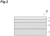
- FIG. 2 is a schematic sectional view of a sound absorbing material according to one embodiment.
- a sound absorbing material 20 includes a protective layer 1, a resin layer 4, and a first substrate layer 2 having a communication hole and a second substrate layer 3 having a communication hole, as a substrate layer, in this order.
- the substrate layer having a communication hole examples include a resin foam, a non-woven fabric, a polymeric porous body, and a porous ceramic.
- the substrate layer may be the resin foam or the non-woven fabric, from the viewpoint of being excellent in sound absorbing properties in a low-frequency region.
- the first substrate layer and the second substrate layer may contain the same material, or may contain different materials.
- the material of the resin foam examples include a polyethylene resin, a polypropylene resin, a polyurethane resin, a polyester resin, an acrylic resin, a polystyrene resin, a melamine resin, a silicone resin, natural rubber, and synthetic rubber.
- the material of the resin foam may be the melamine resin, from the viewpoint of heat resistance, flame resistance, and the like.
- Examples of the fiber configuring the non-woven fabric include an organic fiber and an inorganic fiber.
- Examples of the organic fiber include a polyolefin fiber such as (low-density or high-density) polyethylene, polypropylene (PP), copolymerized polyethylene, and copolymerized polypropylene, a polyester fiber such as polyethylene terephthalate (PET), polytrimethylene terephthalate, polybutylene terephthalate, polyethylene naphthalate, and polybutylene naphthalate, a polyamide fiber, an acrylic fiber, a nylon fiber, a rayon fiber, and a natural fiber such as wool.
- examples of the inorganic fiber include a glass fiber, a metal fiber, a ceramic fiber, and a carbon fiber.
- the fiber configuring the non-woven fabric may include one type or two or more types of the fibers.
- the thickness of the substrate layer can be 0.1 to 50 mm, and may be 0.5 to 20 mm, or may be 2.0 to 10 mm, from the viewpoint of being excellent in the sound absorbing properties in the low-frequency region.
- the first substrate layer and the second substrate layer may have the same thickness, or may have different thicknesses.
- the thickness of the first substrate layer (the substrate layer on the sound incidence side) may be less than the thickness of the second substrate layer, from the viewpoint of being excellent in the sound absorbing properties in the low-frequency region.
- the areal weight of the substrate layer can be 50 to 2000 g/m 2 , and may be 100 to 1000 g/m 2 , from the viewpoint of being excellent in the sound absorbing properties in the low-frequency region.
- the sound absorbing material may further include another substrate layer having a communication hole, from the viewpoint of being excellent in the sound absorbing properties in the low-frequency region. That is, the sound absorbing material may further include a third substrate layer having a communication hole, a fourth substrate layer having a communication hole, and the like, in addition to the first substrate layer having a communication hole and the second substrate layer having a communication hole.
- Each of the substrate layers may contain the same material, or may contain different materials.
- a flexibility-toughness value of the protective layer which is represented by Formula (I) described below, is 1 to 75 MPa/ ⁇ m.
- the flexibility-toughness value may be 2 to 70 MPa/ ⁇ m, or may be 5 to 65 MPa/ ⁇ m, from the viewpoint of making the sound absorbing properties and the durability compatible at a higher level.
- Flexibility ⁇ Toughness Value Tensile Modulus MPa of Protective Layer at 25 ° C ⁇ Shore A Hardness of Protective Layer / Protective Layer Thickness ⁇ m
- the flexibility-toughness value is a property value set by focusing on the degree of shock absorbance per unit thickness and the degree of shock endurance of the protective layer.
- the degree of shock absorbance per unit thickness can be evaluated on the basis of the shore A hardness
- the degree of shock endurance can be evaluated on the basis of the tensile modulus
- the fact that the product of both of the degrees is in a predetermined range indicates that the protective layer has suitable flexibility-toughness.
- the tensile modulus is measured by a tensile tester. Specifically, a sample of 20 mm ⁇ 50 mm is prepared, and the maximum value of an elastic modulus at 25°C when the sample is pulled at a tensile rate of 100 mm/min by using the tensile tester is set to the tensile modulus.
- the tensile modulus can be 1 to 2000 MPa, and may be 10 to 1000 MPa, from the viewpoint of the durability.
- the shore A hardness is measured by a durometer (type A). Specifically, a sample of 20 mm ⁇ 50 mm is prepared, and the sample is stacked to have a thickness of 1 mm or more, and is left to stand in the environment of 25°C for 1 hour. A value within 1 second (or a value represented immediately after measurement) when the hardness of the sample after still standing is measured with the durometer is set to the shore A hardness.
- the shore A hardness can be 20 to 95, and may be 30 to 92, from the viewpoint of the durability.
- the protective layer thickness is measured by a thickness gauge.
- the protective layer thickness can be 10 to 2000 ⁇ m, and may be 50 to 500 ⁇ m, from the viewpoint of the durability.
- Examples of a method for adjusting the elastic modulus and the shore A hardness include adjusting the density of the protective layer, imparting a rigid component into the material, and increasing the ratio of an inorganic component in the material, such as a metal, a ceramic, and silica.
- the elastic modulus and the shore A hardness can also be adjusted by adjusting a void volume in the protective layer.
- the elastic modulus and the shore A hardness can also be adjusted in accordance with a skeleton component configuring the protective layer having a void, the thickness of the skeleton, a method for binding the skeleton, and the like.
- Either the elastic modulus or the shore A hardness can be adjusted by suitably combining the methods described above. For example, by increasing the thickness of the skeleton configuring the protective layer while providing the void in the protective layer, it is possible to decrease the shore A hardness while maintaining the elastic modulus.
- the protective layer may be a layer containing an elastomer, from the viewpoint of making the sound absorbing properties and the durability compatible at a higher level.
- the elastomer capable of satisfying the flexibility-toughness value include a thermoplastic elastomer and a thermosetting elastomer.
- thermoplastic elastomer examples include resins such as a polyolefin-based resin, a polystyrene-based resin, a polyurethane-based resin, a polyester-based resin, a polyether-based resin, a polyacrylic resin, a polyamide-based resin, vinyl chloride, a chlorinated polyethylene-based resin, a polydiene-based resin, a fluorine-based resin, a silicone-based resin, and a polycarbonate-based resin, or modified resins thereof.
- resins such as a polyolefin-based resin, a polystyrene-based resin, a polyurethane-based resin, a polyester-based resin, a polyether-based resin, a polyacrylic resin, a polyamide-based resin, vinyl chloride, a chlorinated polyethylene-based resin, a polydiene-based resin, a fluorine-based resin, a silicone-based resin, and a polycarbonate-based resin, or modified resin
- thermosetting elastomer examples include resins such as a fluorine-based resin, a silicone-based resin, a urethane-based resin, and an epoxy-based resin, synthetic rubber such as isoprene rubber, ethylene propylene rubber, ethylene propylene diene rubber, and nitrile rubber (NBR), or natural rubber, or modified resins thereof.
- resins such as a fluorine-based resin, a silicone-based resin, a urethane-based resin, and an epoxy-based resin, synthetic rubber such as isoprene rubber, ethylene propylene rubber, ethylene propylene diene rubber, and nitrile rubber (NBR), or natural rubber, or modified resins thereof.
- the polyurethane-based resin or the polyester-based resin is preferable from the viewpoint of a decrease in the thickness for a decrease in the weight, the heat resistance, the durability, and the like.
- the layer containing the elastomer may contain other components in addition to the elastomer.
- the other components include inorganic particles such as silica, alumina, and talc, metal particles, and organic resin particles, from the viewpoint of improving the heat resistance, the durability, sound absorbency, vibration-damping properties, sound insulating properties, and the like, and include hollow particles, from the viewpoint of decreasing the weight.
- the layer containing the elastomer may contain a foaming material, an air-bubble portion by foam molding, and the like, from the viewpoint of decreasing the weight.
- the protective layer may be a non-woven fabric, from the viewpoint of making the sound absorbing properties and the durability compatible at a higher level.
- the non-woven fabric capable of satisfying the flexibility-toughness value include a non-woven fabric obtained by rigidly binding fibers, from the viewpoint of the durability, and for example, include a non-woven fabric (such as a PET non-woven fabric) produced by a chemical bonding method, a thermal bonding method, a needle-punching method, and the like.
- the surface weight (the weight per unit area) of the protective layer can be 10 to 1000 g/m 2 , and may be 50 to 800 g/m 2 , from the viewpoint of making the sound absorbing properties and the durability compatible at a higher level.
- the density of the protective layer can be 0.1 to 10.0 g/cm 3 , and may be 0.2 to 2.0 g/cm 3 , from the viewpoint of making the sound absorbing properties and the durability compatible at a higher level.
- the average fiber diameter of the fiber configuring the non-woven fabric can be 0.1 to 100 ⁇ m, and may be 1 to 50 ⁇ m, from the viewpoint of making the sound absorbing properties and the durability compatible at a higher level.
- the average fiber diameter is obtained by averaging fiber diameters of each of the fibers measured from a picture captured at 1000 magnifications with an electron microscope. Specifically, the average fiber diameter is obtained by measuring fiber diameters of a total of 100 fibers arbitrarily selected from 10 pictures to a diameter of 0.1 ⁇ m order, averaging the fiber diameters, and rounding off the second place after the decimal point.
- the sound absorbing material may further include the resin layer between the protective layer and the substrate layer, from the viewpoint of improving the sound absorbing properties, improving the durability, imparting functionality, and the like.
- the resin configuring the resin layer include a polyolefin-based resin such as (low-density or high-density) polyethylene, (stretched or unstretched) polypropylene, copolymerized polyethylene, and copolymerized polypropylene, a polyester-based resin such as polyethylene terephthalate, polytrimethylene terephthalate, polybutylene terephthalate, polyethylene naphthalate, and polybutylene naphthalate, a fluorine-based resin such as PTFE, FEP, and PFA, a polyimide-based resin, a polyamide-based resin, an aramid-based resin, a vinyl chloride-based resin, an acrylic resin, a polycarbonate-based resin, a polyphenylene sulfide-based resin,
- the thickness of the resin layer can be 0.5 to 500 ⁇ m, and may be 5 to 250 ⁇ m, or may be 10 to 100 ⁇ m, from the viewpoint of being excellent in the sound absorbing properties in the low-frequency region.
- the resin layer may include a metal deposition layer on the surface, from the viewpoint of imparting a function of improving a sound absorbing effect by adjusting film properties and a function of reflecting heat. That is, the sound absorbing material may further include the metal deposition layer on the surface of the resin layer.
- the metal deposition layer can be formed by physical deposition such as vacuum deposition or chemical deposition of a metal such as aluminum, copper, zinc, a zinc alloy, and silver.
- the metal deposition layer may be provided on both surfaces of the resin layer, or may be provided on one surface.
- the resin layer may be a perforated film, from the viewpoint of improving the sound absorbing effect of the low-frequency region and adjusting a sound absorbing frequency peak.
- the perforated film may have holes arranged into the shape of a lattice or a rhombus.
- the hole may be in the shape of a circle having a diameter of 0.1 to 50.0 mm, may be in the shape of a circle having a diameter of 0.2 to 10.0 mm, or may be in the shape of a circle having a diameter of 0.3 to 5.0 mm, from the viewpoint of being excellent in the sound absorbing properties in the low-frequency region.
- the shape of the hole may be circular, elliptical, rectangular, polygonal, or the like.
- the sound absorbing material may further include a bonding adhesive layer between the respective layers described above.
- the sound absorbing material may include the bonding adhesive layer at least between the protective layer and the first substrate layer, and between the first substrate layer and the second substrate layer.
- the sound absorbing material may include the bonding adhesive layer at least between the protective layer and the resin layer, between the resin layer and the first substrate layer, and between the first substrate layer and the second substrate layer.
- the bonding adhesive layer examples include a layer containing a bonding adhesive component such as a vinyl acetate resin, a polyolefin resin, an ethylene/vinyl acetate copolymer resin, an isobutene/maleic anhydride copolymer resin, an acrylic copolymer resin, an acrylic monomer, an acrylic oligomer, styrene/butadiene rubber, a vinyl chloride resin, chloroprene rubber, nitrile rubber, a urethane resin, a silylated urethane resin, an epoxy resin, a modified epoxy resin, a polyethylene resin, an ionomer resin, a silicone resin, a modified silicone resin, water glass, and silicate; and a laminated product (for example, a double-faced tape) having a layer containing the bonding adhesive component on both surfaces of a support composed of a paper, a fabric, a resin film, a metal tape, or the like.
- a bonding adhesive component
- the thickness of the bonding adhesive layer is not particularly limited, but can be 0.01 to 500 ⁇ m, and may be 1 to 250 ⁇ m. Each of the bonding adhesive layers may have the same thickness, or may have different thicknesses.
- the weight of the bonding adhesive layer is not particularly limited, but can be 1 to 500 g/m 2 , and may be 5 to 200 g/m 2 , or may be 10 to 150 g/m 2 .
- Each of the bonding adhesive layers may have the same weight, or may have different weights.
- the thickness of the sound absorbing material can be 1 to 100 mm, and may be 2 to 50 mm, or may be 5 to 30 mm, from the viewpoint of the exhibition of the sound absorbing properties, material workability, space-saving, and the like.
- the average normal incidence sound absorption coefficient of the sound absorbing material at 500 to 1000 Hz which is measured on the basis of JIS A 1405-1, can be 0.45 or more, and may be 0.5 or more, from the viewpoint of excellent sound absorbing properties in the low-frequency region. From the same viewpoint, the maximum normal incidence sound absorption coefficient of the sound absorbing material at 500 to 1000 Hz can be 0.65 or more, and may be 0.7 or more.
- the sound absorbing material can be produced by laminating each of the layers.
- the sound absorbing material may be used in a state where the layers adhere to each other by including the bonding adhesive layer as described above, or may be used in a state where the layers do not adhere to each other.
- the bonding adhesive layer may be provided only between some layers.
- the laminate configuring the sound absorbing material may be used in the state of being contained in a housing.
- the sound absorbing material described above is excellent not only in the sound absorbing properties in the low-frequency region, but also in the durability. Accordingly, the sound absorbing material can be preferably used in the applications of an automobile, a rail vehicle, an aircraft, a vessel, a building such as a house, and the like.
- the low-frequency region can be a region in which a frequency is 1000 Hz or less, and the sound absorbing material has excellent sound absorbing properties in a frequency region of 250 to 1000 Hz, in particular, 500 to 1000 Hz.
- a vehicle member includes the sound absorbing material described above. Examples of the vehicle member include the following aspects.
- the vehicle member may be an automobile member.
- Exterior a vehicle member and an exterior material for a vehicle, which are a sound absorbing member of an exterior material for a vehicle.
- Examples of the exterior include an undercover or an under protector, and a soundproof cover (for a vehicle), and specifically include an engine undercover, a floor undercover, a rear undercover, a transmission cover, a fender liner/protector, and a mud guard.
- Interior a vehicle member and an interior material for a vehicle, which are a sound absorbing member of an interior material for a vehicle.
- Examples of the interior include a silencer for a vehicle and a soundproofing for a vehicle, and specifically include a ceiling material (a roof silencer), a dashboard silencer, a floor silencer, a floor carpet, and a hood silencer.
- a ceiling material a roof silencer
- a dashboard silencer a dashboard silencer
- a floor silencer a floor carpet
- a hood silencer a ceiling material
- Examples of the sound absorbing material for a tire include a sound absorbing structure obtained by combining a cover for a vehicle, a case, and the like with the sound absorbing materials described above.
- a sound absorbing material including: a protective layer; a first substrate layer having a communication hole; and a second substrate layer having a communication hole, in this order, in which a flexibility-toughness value of the protective layer, which is represented by Formula (I) described below, is 1 to 75 [MPa/ ⁇ m].
- Flexibility ⁇ Toughness Value Tensile Modulus MPa of Protective Layer at 25 ° C ⁇ Shore A Hardness of Protective Layer / Protective Layer Thickness ⁇ m
- the protective layer is a layer containing an elastomer.
- the sound absorbing material described above further including a resin layer between the protective layer and the first substrate layer.
- the resin layer contains polyolefin, polyester, or polyamide.
- the sound absorbing material described above further including a metal deposition layer on at least any one surface of the resin layer.
- the sound absorbing material described above in which a thickness is 1 to 100 mm.
- a vehicle member including the sound absorbing material described above.
- Thickness The protective layer was cut into 200 mm ⁇ 200 mm piece and its thickness was measured using a thickness gauge (a digital thickness gauge JAN-257 with a gauge head of ⁇ 20 mm, manufactured by OZAKI MFG. CO., LTD.). The average value of a total of 5 measurement spots including the center and four corners was set to the thickness of the protective layer.
- a thickness gauge a digital thickness gauge JAN-257 with a gauge head of ⁇ 20 mm, manufactured by OZAKI MFG. CO., LTD.
- Tensile modulus The tensile modulus was measured by a tensile tester (EZ-Test, manufactured by SHIMADZU CORPORATION). A sample of 20 mm ⁇ 50 mm was prepared, and the maximum elastic modulus at 25°C when the sample was pulled at a tensile rate of 100 mm/min by using the tensile tester was set to the tensile modulus. In a case where there are a TD direction and an MD direction, the lower elastic modulus was adopted. The measurement was performed 3 times, and the average value thereof was set to the tensile modulus of the protective layer.
- Shore A hardness The shore A hardness was measured by a durometer (type A). A sample of 20 mm ⁇ 50 mm was prepared, and the sample was stacked to have a thickness of 1 mm or more, and the hardness of the stacked sample measured with the durometer was set to the shore A hardness. The average value of a total of 5 measurement spots including the center and four corners was set to the shore A hardness of the protective layer.
- Double-faced aluminum deposition polyethylene terephthalate film AlPET: a thickness of 12 ⁇ m
- Double-faced tape Hi-Bon 11-652, manufactured by Showa Denko Materials Co., Ltd., a thickness of 0.12 mm
- the normal incidence sound absorption coefficient of each of the prepared sound absorbing materials was measured as follows. A sound was incident from the protective layer side. The average value of the normal incidence sound absorption coefficients at 500 to 1000 Hz was calculated as the average sound absorption coefficient, and the maximum value of the normal incidence sound absorption coefficients was set to the maximum sound absorption coefficient. In a case where the average sound absorption coefficient was 0.45 or more, and the maximum sound absorption coefficient was 0.65 or more, it was determined that the sound absorbing material was excellent in sound absorbing properties in a low-frequency region (500 to 1000 Hz). Results are shown in Table 4 and Table 5.
- the durability (the chipping resistance) of each of the prepared sound absorbing materials was evaluated.
- Gravel Test Instrument JA400 manufactured by Suga Test Instruments Co., Ltd.
- 850 g of No. 7 crushed stone was applied to the protective layer at a pressure of 0.4 MPa.
- the state of the surface of the protective layer was visually checked, and the durability was evaluated on the basis of the following criteria.
- a or B it was determined that the sound absorbing material was excellent in the durability. Results are shown in Table 4 and Table 5.
- 1 protective layer
- 2 first substrate layer having communication hole
- 3 second substrate layer having communication hole
- 4 resin layer
- 10, 20 sound absorbing material
Landscapes
- Engineering & Computer Science (AREA)
- Textile Engineering (AREA)
- Physics & Mathematics (AREA)
- Acoustics & Sound (AREA)
- Mechanical Engineering (AREA)
- Multimedia (AREA)
- Laminated Bodies (AREA)
Abstract
Description
- The present invention relates to a sound absorbing material and a vehicle member.
- As a sound absorbing material excellent in sound absorbing properties in a low-frequency region, a sound absorbing material formed by stacking two layers of non-woven fabric or the like is known (for example, Patent Literature 1).
- Patent Literature 1: International Publication
WO 2020/213685 - In the case of the sound absorbing material formed from the non-woven fabric, in particular, there is room for improvement in terms of durability against a mechanical shock from the outside.
- The present invention has been made in consideration of the circumstance described above, and an object thereof is to provide a sound absorbing material excellent in sound absorbing properties in a low-frequency region and durability. In addition, another object of the present invention is to provide a vehicle member including the sound absorbing material described above.
- One aspect of the present invention relates to a sound absorbing material, including: a protective layer; a first substrate layer having a communication hole; and a second substrate layer having a communication hole, in this order, in which a flexibility-toughness value of the protective layer, which is represented by Formula (I) described below, is 1 to 75 [MPa/µm].

- In one aspect, the protective layer may be a layer containing an elastomer.
- In one aspect, the protective layer may be a non-woven fabric.
- In one aspect, the sound absorbing material may further include a resin layer between the protective layer and the first substrate layer.
- In one aspect, the resin layer may contain polyolefin, polyester, or polyamide.
- In one aspect, the sound absorbing material may further include a metal deposition layer on at least any one surface of the resin layer.
- In one aspect, the first substrate layer and the second substrate layer may be a resin foam or a non-woven fabric.
- In one aspect, a thickness of the first substrate layer may be less than a thickness of the second substrate layer.
- In one aspect, a thickness of the sound absorbing material may be 1 to 100 mm.
- One aspect of the present invention relates to a vehicle member including the sound absorbing material described above.
- According to the present invention, it is possible to provide the sound absorbing material excellent in the sound absorbing properties in the low-frequency region and the durability. In addition, according to the present invention, it is possible to provide the vehicle member including the sound absorbing material described above.
-
-
FIG. 1 is a schematic sectional view of a sound absorbing material according to one embodiment. -
FIG. 2 is a schematic sectional view of a sound absorbing material according to one embodiment. - Hereinafter, in some cases, an embodiment of the present invention will be described in detail, with reference to the drawings. Note that, in this specification, a numerical range represented by using "to" indicates a range including numerical values described before and after "to" as the minimum value and the maximum value, respectively. In addition, in the numerical range described in this specification, the upper limit value or the lower limit value of the numerical range may be replaced with values described in Examples.
-
FIG. 1 is a schematic sectional view of a sound absorbing material according to one embodiment. Asound absorbing material 10 includes aprotective layer 1, and afirst substrate layer 2 having a communication hole and asecond substrate layer 3 having a communication hole, as a substrate layer, in this order. A sound (sound energy) incident from the protective layer side is dissipated as heat energy when passing through the sound absorbing material. Accordingly, the attenuation of the sound is observed. -
FIG. 2 is a schematic sectional view of a sound absorbing material according to one embodiment. Asound absorbing material 20 includes aprotective layer 1, aresin layer 4, and afirst substrate layer 2 having a communication hole and asecond substrate layer 3 having a communication hole, as a substrate layer, in this order. - Examples of the substrate layer having a communication hole include a resin foam, a non-woven fabric, a polymeric porous body, and a porous ceramic. Among them, the substrate layer may be the resin foam or the non-woven fabric, from the viewpoint of being excellent in sound absorbing properties in a low-frequency region. The first substrate layer and the second substrate layer may contain the same material, or may contain different materials.
- Examples of the material of the resin foam include a polyethylene resin, a polypropylene resin, a polyurethane resin, a polyester resin, an acrylic resin, a polystyrene resin, a melamine resin, a silicone resin, natural rubber, and synthetic rubber. The material of the resin foam may be the melamine resin, from the viewpoint of heat resistance, flame resistance, and the like.
- Examples of the fiber configuring the non-woven fabric include an organic fiber and an inorganic fiber. Examples of the organic fiber include a polyolefin fiber such as (low-density or high-density) polyethylene, polypropylene (PP), copolymerized polyethylene, and copolymerized polypropylene, a polyester fiber such as polyethylene terephthalate (PET), polytrimethylene terephthalate, polybutylene terephthalate, polyethylene naphthalate, and polybutylene naphthalate, a polyamide fiber, an acrylic fiber, a nylon fiber, a rayon fiber, and a natural fiber such as wool. In addition, examples of the inorganic fiber include a glass fiber, a metal fiber, a ceramic fiber, and a carbon fiber. The fiber configuring the non-woven fabric may include one type or two or more types of the fibers.
- The thickness of the substrate layer can be 0.1 to 50 mm, and may be 0.5 to 20 mm, or may be 2.0 to 10 mm, from the viewpoint of being excellent in the sound absorbing properties in the low-frequency region. The first substrate layer and the second substrate layer may have the same thickness, or may have different thicknesses. The thickness of the first substrate layer (the substrate layer on the sound incidence side) may be less than the thickness of the second substrate layer, from the viewpoint of being excellent in the sound absorbing properties in the low-frequency region.
- The areal weight of the substrate layer can be 50 to 2000 g/m2, and may be 100 to 1000 g/m2, from the viewpoint of being excellent in the sound absorbing properties in the low-frequency region.
- The sound absorbing material may further include another substrate layer having a communication hole, from the viewpoint of being excellent in the sound absorbing properties in the low-frequency region. That is, the sound absorbing material may further include a third substrate layer having a communication hole, a fourth substrate layer having a communication hole, and the like, in addition to the first substrate layer having a communication hole and the second substrate layer having a communication hole. Each of the substrate layers may contain the same material, or may contain different materials.
- A flexibility-toughness value of the protective layer, which is represented by Formula (I) described below, is 1 to 75 MPa/µm. The flexibility-toughness value may be 2 to 70 MPa/µm, or may be 5 to 65 MPa/µm, from the viewpoint of making the sound absorbing properties and the durability compatible at a higher level.

- The flexibility-toughness value is a property value set by focusing on the degree of shock absorbance per unit thickness and the degree of shock endurance of the protective layer. The degree of shock absorbance per unit thickness can be evaluated on the basis of the shore A hardness, the degree of shock endurance can be evaluated on the basis of the tensile modulus, and the fact that the product of both of the degrees is in a predetermined range indicates that the protective layer has suitable flexibility-toughness.
- The tensile modulus is measured by a tensile tester. Specifically, a sample of 20 mm × 50 mm is prepared, and the maximum value of an elastic modulus at 25°C when the sample is pulled at a tensile rate of 100 mm/min by using the tensile tester is set to the tensile modulus. There is no particular limitation insofar as the formula described above is satisfied, and the tensile modulus can be 1 to 2000 MPa, and may be 10 to 1000 MPa, from the viewpoint of the durability.
- The shore A hardness is measured by a durometer (type A). Specifically, a sample of 20 mm × 50 mm is prepared, and the sample is stacked to have a thickness of 1 mm or more, and is left to stand in the environment of 25°C for 1 hour. A value within 1 second (or a value represented immediately after measurement) when the hardness of the sample after still standing is measured with the durometer is set to the shore A hardness. There is no particular limitation insofar as the formula described above is satisfied, and the shore A hardness can be 20 to 95, and may be 30 to 92, from the viewpoint of the durability.
- The protective layer thickness is measured by a thickness gauge. There is no particular limitation insofar as the formula described above is satisfied, and the protective layer thickness can be 10 to 2000 µm, and may be 50 to 500 µm, from the viewpoint of the durability.
- In order to set the flexibility-toughness value to be in the predetermined range, for example, it is considered to adjust each of the properties, from the following viewpoint.
- Examples of a method for adjusting the elastic modulus and the shore A hardness include adjusting the density of the protective layer, imparting a rigid component into the material, and increasing the ratio of an inorganic component in the material, such as a metal, a ceramic, and silica. The elastic modulus and the shore A hardness can also be adjusted by adjusting a void volume in the protective layer. The elastic modulus and the shore A hardness can also be adjusted in accordance with a skeleton component configuring the protective layer having a void, the thickness of the skeleton, a method for binding the skeleton, and the like.
- Either the elastic modulus or the shore A hardness, for example, can be adjusted by suitably combining the methods described above. For example, by increasing the thickness of the skeleton configuring the protective layer while providing the void in the protective layer, it is possible to decrease the shore A hardness while maintaining the elastic modulus.
- The protective layer may be a layer containing an elastomer, from the viewpoint of making the sound absorbing properties and the durability compatible at a higher level. Examples of the elastomer capable of satisfying the flexibility-toughness value include a thermoplastic elastomer and a thermosetting elastomer. Examples of the thermoplastic elastomer include resins such as a polyolefin-based resin, a polystyrene-based resin, a polyurethane-based resin, a polyester-based resin, a polyether-based resin, a polyacrylic resin, a polyamide-based resin, vinyl chloride, a chlorinated polyethylene-based resin, a polydiene-based resin, a fluorine-based resin, a silicone-based resin, and a polycarbonate-based resin, or modified resins thereof. In addition, examples of the thermosetting elastomer include resins such as a fluorine-based resin, a silicone-based resin, a urethane-based resin, and an epoxy-based resin, synthetic rubber such as isoprene rubber, ethylene propylene rubber, ethylene propylene diene rubber, and nitrile rubber (NBR), or natural rubber, or modified resins thereof. The polyurethane-based resin or the polyester-based resin is preferable from the viewpoint of a decrease in the thickness for a decrease in the weight, the heat resistance, the durability, and the like.
- The layer containing the elastomer may contain other components in addition to the elastomer. Examples of the other components include inorganic particles such as silica, alumina, and talc, metal particles, and organic resin particles, from the viewpoint of improving the heat resistance, the durability, sound absorbency, vibration-damping properties, sound insulating properties, and the like, and include hollow particles, from the viewpoint of decreasing the weight. The layer containing the elastomer may contain a foaming material, an air-bubble portion by foam molding, and the like, from the viewpoint of decreasing the weight.
- The protective layer may be a non-woven fabric, from the viewpoint of making the sound absorbing properties and the durability compatible at a higher level. Examples of the non-woven fabric capable of satisfying the flexibility-toughness value include a non-woven fabric obtained by rigidly binding fibers, from the viewpoint of the durability, and for example, include a non-woven fabric (such as a PET non-woven fabric) produced by a chemical bonding method, a thermal bonding method, a needle-punching method, and the like.
- The surface weight (the weight per unit area) of the protective layer can be 10 to 1000 g/m2, and may be 50 to 800 g/m2, from the viewpoint of making the sound absorbing properties and the durability compatible at a higher level.
- The density of the protective layer can be 0.1 to 10.0 g/cm3, and may be 0.2 to 2.0 g/cm3, from the viewpoint of making the sound absorbing properties and the durability compatible at a higher level.
- In a case where the protective layer is the non-woven fabric, the average fiber diameter of the fiber configuring the non-woven fabric can be 0.1 to 100 µm, and may be 1 to 50 µm, from the viewpoint of making the sound absorbing properties and the durability compatible at a higher level.
- The average fiber diameter is obtained by averaging fiber diameters of each of the fibers measured from a picture captured at 1000 magnifications with an electron microscope. Specifically, the average fiber diameter is obtained by measuring fiber diameters of a total of 100 fibers arbitrarily selected from 10 pictures to a diameter of 0.1 µm order, averaging the fiber diameters, and rounding off the second place after the decimal point.
- The sound absorbing material may further include the resin layer between the protective layer and the substrate layer, from the viewpoint of improving the sound absorbing properties, improving the durability, imparting functionality, and the like. Examples of the resin configuring the resin layer include a polyolefin-based resin such as (low-density or high-density) polyethylene, (stretched or unstretched) polypropylene, copolymerized polyethylene, and copolymerized polypropylene, a polyester-based resin such as polyethylene terephthalate, polytrimethylene terephthalate, polybutylene terephthalate, polyethylene naphthalate, and polybutylene naphthalate, a fluorine-based resin such as PTFE, FEP, and PFA, a polyimide-based resin, a polyamide-based resin, an aramid-based resin, a vinyl chloride-based resin, an acrylic resin, a polycarbonate-based resin, a polyphenylene sulfide-based resin, a polyvinyl alcohol-based resin, a polystyrene-based resin, a polyacrylonitrile-based resin, and an ethylene/vinyl acetate-based resin. The resin layer is a layer (a film) not having a communication hole.
- The thickness of the resin layer can be 0.5 to 500 µm, and may be 5 to 250 µm, or may be 10 to 100 µm, from the viewpoint of being excellent in the sound absorbing properties in the low-frequency region.
- The resin layer may include a metal deposition layer on the surface, from the viewpoint of imparting a function of improving a sound absorbing effect by adjusting film properties and a function of reflecting heat. That is, the sound absorbing material may further include the metal deposition layer on the surface of the resin layer. The metal deposition layer can be formed by physical deposition such as vacuum deposition or chemical deposition of a metal such as aluminum, copper, zinc, a zinc alloy, and silver. The metal deposition layer may be provided on both surfaces of the resin layer, or may be provided on one surface.
- The resin layer may be a perforated film, from the viewpoint of improving the sound absorbing effect of the low-frequency region and adjusting a sound absorbing frequency peak. The perforated film may have holes arranged into the shape of a lattice or a rhombus. The hole may be in the shape of a circle having a diameter of 0.1 to 50.0 mm, may be in the shape of a circle having a diameter of 0.2 to 10.0 mm, or may be in the shape of a circle having a diameter of 0.3 to 5.0 mm, from the viewpoint of being excellent in the sound absorbing properties in the low-frequency region. The shape of the hole may be circular, elliptical, rectangular, polygonal, or the like.
- The sound absorbing material may further include a bonding adhesive layer between the respective layers described above. The sound absorbing material may include the bonding adhesive layer at least between the protective layer and the first substrate layer, and between the first substrate layer and the second substrate layer. In addition, the sound absorbing material may include the bonding adhesive layer at least between the protective layer and the resin layer, between the resin layer and the first substrate layer, and between the first substrate layer and the second substrate layer.
- Examples of the bonding adhesive layer include a layer containing a bonding adhesive component such as a vinyl acetate resin, a polyolefin resin, an ethylene/vinyl acetate copolymer resin, an isobutene/maleic anhydride copolymer resin, an acrylic copolymer resin, an acrylic monomer, an acrylic oligomer, styrene/butadiene rubber, a vinyl chloride resin, chloroprene rubber, nitrile rubber, a urethane resin, a silylated urethane resin, an epoxy resin, a modified epoxy resin, a polyethylene resin, an ionomer resin, a silicone resin, a modified silicone resin, water glass, and silicate; and a laminated product (for example, a double-faced tape) having a layer containing the bonding adhesive component on both surfaces of a support composed of a paper, a fabric, a resin film, a metal tape, or the like. Each of the bonding adhesive layers may contain the same material, or may contain different materials.
- The thickness of the bonding adhesive layer is not particularly limited, but can be 0.01 to 500 µm, and may be 1 to 250 µm. Each of the bonding adhesive layers may have the same thickness, or may have different thicknesses.
- The weight of the bonding adhesive layer is not particularly limited, but can be 1 to 500 g/m2, and may be 5 to 200 g/m2, or may be 10 to 150 g/m2. Each of the bonding adhesive layers may have the same weight, or may have different weights.
- The thickness of the sound absorbing material can be 1 to 100 mm, and may be 2 to 50 mm, or may be 5 to 30 mm, from the viewpoint of the exhibition of the sound absorbing properties, material workability, space-saving, and the like.
- The average normal incidence sound absorption coefficient of the sound absorbing material at 500 to 1000 Hz, which is measured on the basis of JIS A 1405-1, can be 0.45 or more, and may be 0.5 or more, from the viewpoint of excellent sound absorbing properties in the low-frequency region. From the same viewpoint, the maximum normal incidence sound absorption coefficient of the sound absorbing material at 500 to 1000 Hz can be 0.65 or more, and may be 0.7 or more.
- The sound absorbing material can be produced by laminating each of the layers. The sound absorbing material may be used in a state where the layers adhere to each other by including the bonding adhesive layer as described above, or may be used in a state where the layers do not adhere to each other. In addition, the bonding adhesive layer may be provided only between some layers. The laminate configuring the sound absorbing material may be used in the state of being contained in a housing.
- The sound absorbing material described above is excellent not only in the sound absorbing properties in the low-frequency region, but also in the durability. Accordingly, the sound absorbing material can be preferably used in the applications of an automobile, a rail vehicle, an aircraft, a vessel, a building such as a house, and the like. Here, the low-frequency region can be a region in which a frequency is 1000 Hz or less, and the sound absorbing material has excellent sound absorbing properties in a frequency region of 250 to 1000 Hz, in particular, 500 to 1000 Hz.
- A vehicle member includes the sound absorbing material described above. Examples of the vehicle member include the following aspects. The vehicle member may be an automobile member.
- Exterior: a vehicle member and an exterior material for a vehicle, which are a sound absorbing member of an exterior material for a vehicle.
- Examples of the exterior include an undercover or an under protector, and a soundproof cover (for a vehicle), and specifically include an engine undercover, a floor undercover, a rear undercover, a transmission cover, a fender liner/protector, and a mud guard.
- Interior: a vehicle member and an interior material for a vehicle, which are a sound absorbing member of an interior material for a vehicle.
- Examples of the interior include a silencer for a vehicle and a soundproofing for a vehicle, and specifically include a ceiling material (a roof silencer), a dashboard silencer, a floor silencer, a floor carpet, and a hood silencer.
- Others: a sound absorbing material for a tire.
- Examples of the sound absorbing material for a tire include a sound absorbing structure obtained by combining a cover for a vehicle, a case, and the like with the sound absorbing materials described above.
- A sound absorbing material, including: a protective layer; a first substrate layer having a communication hole; and a second substrate layer having a communication hole, in this order, in which a flexibility-toughness value of the protective layer, which is represented by Formula (I) described below, is 1 to 75 [MPa/µm].

- The sound absorbing material described above, in which the protective layer is a layer containing an elastomer.
- The sound absorbing material described above, in which the protective layer is a non-woven fabric.
- The sound absorbing material described above, further including a resin layer between the protective layer and the first substrate layer.
- The sound absorbing material described above, in which the resin layer contains polyolefin, polyester, or polyamide.
- The sound absorbing material described above, further including a metal deposition layer on at least any one surface of the resin layer.
- The sound absorbing material described above, in which the first substrate layer and the second substrate layer are a resin foam or a non-woven fabric.
- The sound absorbing material described above, in which a thickness of the first substrate layer is less than a thickness of the second substrate layer.
- The sound absorbing material described above, in which a thickness is 1 to 100 mm.
- A vehicle member, including the sound absorbing material described above.
- Hereinafter, the present invention will be described in more detail by Examples, but the present invention is not limited to such Examples.
-
- Substrate 1: a PET non-woven fabric (an areal weight of 200 g/m2, a thickness of 3 mm)
- Substrate 2: a PET non-woven fabric (an areal weight of 250 g/m2, a thickness of 7 mm)
- Protective layers shown in Table 1, Table 2, and Table 3 were prepared.
- Thickness: The protective layer was cut into 200 mm × 200 mm piece and its thickness was measured using a thickness gauge (a digital thickness gauge JAN-257 with a gauge head of φ20 mm, manufactured by OZAKI MFG. CO., LTD.). The average value of a total of 5 measurement spots including the center and four corners was set to the thickness of the protective layer.
- Tensile modulus: The tensile modulus was measured by a tensile tester (EZ-Test, manufactured by SHIMADZU CORPORATION). A sample of 20 mm × 50 mm was prepared, and the maximum elastic modulus at 25°C when the sample was pulled at a tensile rate of 100 mm/min by using the tensile tester was set to the tensile modulus. In a case where there are a TD direction and an MD direction, the lower elastic modulus was adopted. The measurement was performed 3 times, and the average value thereof was set to the tensile modulus of the protective layer.
- Shore A hardness: The shore A hardness was measured by a durometer (type A). A sample of 20 mm × 50 mm was prepared, and the sample was stacked to have a thickness of 1 mm or more, and the hardness of the stacked sample measured with the durometer was set to the shore A hardness. The average value of a total of 5 measurement spots including the center and four corners was set to the shore A hardness of the protective layer.
[Table 1] Example E1 E2 E3 Type - Polvurethane elastomer Polvurethane elastomer Polvurethane elastomer Average fiber diameter µmφ - - - Thickness µm 50.1 99.8 501.2 Areal weight g/m2 60.0 116.1 611.9 Density g/cm3 1.20 1.16 1.22 Tensile modulus MPa 32.2 30.5 35.8 Shore A hardness - 85 85 92 Flexibility-touehness value MPa/µm 54.7 25.9 6.6 [Table 2] Example E4 E5 E6 E7 E8 Type - PET non-woven fabric PET non-woven fabric PET non-woven fabric PET non-woven fabric PET non-woven fabric Average fiber diameter µmφ 30.1 6.3 6.3 15.2 22.5 Thickness µm 398.6 402.1 450.1 595.2 430.5 Areal weight g/m2 210.4 100.6 300.0 202.1 100.1 Density g/cm3 0.53 0.25 0.67 0.34 0.23 Tensile modulus MPa 280.4 96.9 340.1 280.4 124.5 Shore A hardness - 88 74 94 85 78 Flexibility-touehness value MPa/µm 61.7 17.9 71.0 40.5 22.6 [Table 3] Comparative Example CE1 CE2 CE3 CE4 CE5 Type - PET film PET film PET film PP film PET non-woven fabric Average fiber diameter µmφ - - - - 6.3 Thickness µm 50.2 250.0 499.1 500.2 199.5 Areal weight g/m2 69.1 350.3 701.0 451.9 100.0 Density g/cm3 1.38 1.40 1.40 0.90 0.50 Tensile modulus MPa 2155.7 852.7 448.6 399.6 422 Shore A hardness - 98 99 99 98 86 Flexibility-touehness value MPa/µm 4268.3 337.7 88.8 78.3 181.5 Comparative Example CE6 CE7 CE8 CE9 CE10 Type - PET non-woven fabric Polyester elastomer Polyurethane elastomer Aluminum foil Aluminum foil Average fiber diameter µmφ 20.5 - - - - Thickness µm 400.0 59.7 31.1 500.2 250.4 Areal weight g/m2 39.8 74.2 36.5 1355.1 680.9 Density g/cm3 0.10 1.23 1.20 2.71 2.72 Tensile modulus MPa 4.13 83.1 28.4 598.6 1272.3 Shore A hardness 75 94 85 98 98 Flexibility-touehness value MPa/µm 0.8 1302 80.5 1173 498.7 - The following resin layer was prepared.
Double-faced aluminum deposition polyethylene terephthalate film (AlPET): a thickness of 12 µm - The following bonding adhesive layer was prepared.
Double-faced tape: Hi-Bon 11-652, manufactured by Showa Denko Materials Co., Ltd., a thickness of 0.12 mm - Sound absorbing materials having configurations shown in Table 4 and Table 5 were prepared. The double-faced tape was used in the bonding adhesion of each of the layers.
- The normal incidence sound absorption coefficient of each of the prepared sound absorbing materials was measured as follows. A sound was incident from the protective layer side. The average value of the normal incidence sound absorption coefficients at 500 to 1000 Hz was calculated as the average sound absorption coefficient, and the maximum value of the normal incidence sound absorption coefficients was set to the maximum sound absorption coefficient. In a case where the average sound absorption coefficient was 0.45 or more, and the maximum sound absorption coefficient was 0.65 or more, it was determined that the sound absorbing material was excellent in sound absorbing properties in a low-frequency region (500 to 1000 Hz). Results are shown in Table 4 and Table 5.
- Device name: a 4206 type impedance tube (manufactured by Brüel & Kjær Sound & Vibration Measurement A/S)
- Measurement method: a normal incidence sound absorption coefficient (based on JIS A 1405-1)
- Measurement range: 50 to 1600 Hz
- The durability (the chipping resistance) of each of the prepared sound absorbing materials was evaluated. In the evaluation, Gravel Test Instrument JA400 (manufactured by Suga Test Instruments Co., Ltd.) was used, and 850 g of No. 7 crushed stone was applied to the protective layer at a pressure of 0.4 MPa. After that, the state of the surface of the protective layer was visually checked, and the durability was evaluated on the basis of the following criteria. In the case of the evaluation of A or B, it was determined that the sound absorbing material was excellent in the durability. Results are shown in Table 4 and Table 5.
- A: There is no perforation and no dent.
- B: There is no perforation but a dent.
- C: There is a perforation (less than 5 spots).
- D: There is a perforation (5 spots or more).
- 1: protective layer, 2: first substrate layer having communication hole, 3: second substrate layer having communication hole, 4: resin layer, 10, 20: sound absorbing material.
| Example | |||||||||
| Protective laver | E1 | E2 | E3 | E4 | E5 | E6 | E7 | E8 | |
| Resin laver | - | - | - | Present | Present | Present | Present | | |
| Substrate layer | |||||||||
| 1 | | | | | | | | | |
| | | | | | | | | | |
| Normal incidence sound absorption coefficient | Average | 0.45 | 0.48 | 0.50 | 0.49 | 0.48 | 0.49 | 0.50 | 0.49 |
| Maximum | 0.66 | 0.72 | 0.65 | 0.71 | 0.69 | 0.65 | 0.68 | 0.66 | |
| Durability | - | B | A | A | A | B | A | A | A |
| Comparative Example | ||||||
| Protective laver | CE1 | CE2 | CE3 | CE4 | CE5 | |
| Resin laver | - | - | - | - | | |
| Substrate laver | ||||||
| 1 | | | | | | |
| | | | | | | |
| Normal incidence sound absorption coefficient | Average | 0.41 | 0.46 | 0.47 | 0.49 | 0.46 |
| Maximum | 0.75 | 0.70 | 0.59 | 0.69 | 0.76 | |
| Durability | - | D | D | C | C | D |
| Comparative Example | ||||||
| Protective laver | CE6 | CE7 | CE8 | CE9 | CE10 | |
| Resin laver | Present | - | - | - | - | |
| | | | | | | |
| | | | | | | |
| Normal incidence sound absorption coefficient | Average | 0.45 | 0.40 | 0.42 | 0.46 | 0.47 |
| Maximum | 0.62 | 0.70 | 0.53 | 0.54 | 0.51 | |
| Durability | - | C | C | D | B | B |
Claims (10)
- A sound absorbing material, comprising:a protective layer;a first substrate layer having a communication hole; anda second substrate layer having a communication hole, in this order,wherein a flexibility-toughness value of the protective layer, which is represented by Formula (I) described below, is 1 to 75 [MPa/µm].

- The sound absorbing material according to claim 1,
wherein the protective layer is a layer containing an elastomer. - The sound absorbing material according to claim 1,
wherein the protective layer is a non-woven fabric. - The sound absorbing material according to any one of claims 1 to 3, further comprising a resin layer between the protective layer and the first substrate layer.
- The sound absorbing material according to claim 4,
wherein the resin layer contains polyolefin, polyester, or polyamide. - The sound absorbing material according to claim 4 or 5, further comprising a metal deposition layer on at least any one surface of the resin layer.
- The sound absorbing material according to any one of claims 1 to 6,
wherein the first substrate layer and the second substrate layer are a resin foam or a non-woven fabric. - The sound absorbing material according to any one of claims 1 to 7,
wherein a thickness of the first substrate layer is less than a thickness of the second substrate layer. - The sound absorbing material according to any one of claims 1 to 8,
wherein a thickness is 1 to 100 mm. - A vehicle member, comprising the sound absorbing material according to any one of claims 1 to 9.
Applications Claiming Priority (1)
| Application Number | Priority Date | Filing Date | Title |
|---|---|---|---|
| PCT/JP2021/015719 WO2022219807A1 (en) | 2021-04-16 | 2021-04-16 | Sound absorbing material, and vehicle member |
Publications (3)
| Publication Number | Publication Date |
|---|---|
| EP4306365A1 true EP4306365A1 (en) | 2024-01-17 |
| EP4306365A4 EP4306365A4 (en) | 2024-04-17 |
| EP4306365B1 EP4306365B1 (en) | 2024-11-20 |
Family
ID=83640300
Family Applications (1)
| Application Number | Title | Priority Date | Filing Date |
|---|---|---|---|
| EP21937001.2A Active EP4306365B1 (en) | 2021-04-16 | 2021-04-16 | Sound absorbing material, and vehicle member |
Country Status (6)
| Country | Link |
|---|---|
| US (1) | US20240217455A1 (en) |
| EP (1) | EP4306365B1 (en) |
| JP (1) | JP7700848B2 (en) |
| CN (1) | CN117121093A (en) |
| TW (1) | TWI909036B (en) |
| WO (1) | WO2022219807A1 (en) |
Families Citing this family (1)
| Publication number | Priority date | Publication date | Assignee | Title |
|---|---|---|---|---|
| EP4739501A1 (en) * | 2023-07-07 | 2026-05-13 | Illinois Tool Works Inc. | Soundproofing membrane |
Family Cites Families (18)
| Publication number | Priority date | Publication date | Assignee | Title |
|---|---|---|---|---|
| US4798756A (en) * | 1987-01-09 | 1989-01-17 | Toyo Tire & Rubber Company Limited | Laminate structure of interior finishing material |
| JPH10226006A (en) * | 1997-02-14 | 1998-08-25 | Kasai Kogyo Co Ltd | Sound-insulating structure |
| JP2003316366A (en) * | 2002-04-23 | 2003-11-07 | Suzuki Motor Corp | Sound absorbing material and method of manufacturing the same |
| TWI651455B (en) * | 2009-01-14 | 2019-02-21 | Kuraray Co., Ltd | Sound insulation board, sound insulation structure and sound insulation method |
| WO2010088769A1 (en) * | 2009-02-03 | 2010-08-12 | Clausi Robert N | Sound attenuating laminate materials |
| TW201438909A (en) * | 2013-03-19 | 2014-10-16 | Nippon Steel & Sumikin Chem Co | Resin laminate and a forming method using the resin laminate |
| JP2014213596A (en) * | 2013-04-30 | 2014-11-17 | 新日鉄住金化学株式会社 | Resin laminate |
| EP2985140B1 (en) * | 2014-08-11 | 2017-12-27 | Ford Global Technologies, LLC | Cladding element for vehicle floor area |
| KR102110094B1 (en) * | 2014-12-18 | 2020-05-12 | 파인웰 씨오., 엘티디 | Hearing device for bicycle riding and bicycle system |
| US9783316B2 (en) * | 2015-06-22 | 2017-10-10 | Rohr, Inc. | Acoustic panel assembly with a folding chamber |
| GB201521075D0 (en) * | 2015-11-30 | 2016-01-13 | Short Brothers Plc | Methods, precursors and abrasive blasting masks for manufacturing noise attenuating devices |
| JP2018141838A (en) * | 2017-02-27 | 2018-09-13 | 日東電工株式会社 | Acoustic absorbent |
| WO2020213139A1 (en) * | 2019-04-18 | 2020-10-22 | 日立化成株式会社 | Sound-absorbing material |
| WO2020213140A1 (en) | 2019-04-18 | 2020-10-22 | 日立化成株式会社 | Sound-absorbing material |
| EP3812151B1 (en) * | 2019-10-25 | 2022-08-03 | Autoneum Management AG | Noise attenuating trim part for a vehicle |
| US11668236B2 (en) * | 2020-07-24 | 2023-06-06 | General Electric Company | Acoustic liners with low-frequency sound wave attenuating features |
| WO2022212658A1 (en) * | 2021-04-01 | 2022-10-06 | Armstrong World Industries, Inc. | Acoustic building panels |
| US12385589B2 (en) * | 2021-08-27 | 2025-08-12 | Dimension Product Solutions LP | Noise suppression unit |
-
2021
- 2021-04-16 WO PCT/JP2021/015719 patent/WO2022219807A1/en not_active Ceased
- 2021-04-16 CN CN202180096521.XA patent/CN117121093A/en active Pending
- 2021-04-16 EP EP21937001.2A patent/EP4306365B1/en active Active
- 2021-04-16 US US18/555,178 patent/US20240217455A1/en active Pending
- 2021-04-16 JP JP2023514300A patent/JP7700848B2/en active Active
-
2022
- 2022-04-14 TW TW111114308A patent/TWI909036B/en active
Also Published As
| Publication number | Publication date |
|---|---|
| WO2022219807A1 (en) | 2022-10-20 |
| EP4306365B1 (en) | 2024-11-20 |
| JPWO2022219807A1 (en) | 2022-10-20 |
| EP4306365A4 (en) | 2024-04-17 |
| JP7700848B2 (en) | 2025-07-01 |
| TWI909036B (en) | 2025-12-21 |
| CN117121093A (en) | 2023-11-24 |
| US20240217455A1 (en) | 2024-07-04 |
| TW202244891A (en) | 2022-11-16 |
Similar Documents
| Publication | Publication Date | Title |
|---|---|---|
| EP2311028B1 (en) | Multilayer sound absorbing sheet and method of absorbing sound | |
| EP1570461B1 (en) | Ultralight trim composite | |
| US11654841B2 (en) | Box-shaped soundproof structure and transportation apparatus | |
| EP2561131A1 (en) | Textile laminar structure for making acoustic components | |
| EP3709291B1 (en) | Sound proof structure | |
| EP4306365B1 (en) | Sound absorbing material, and vehicle member | |
| WO2021182468A1 (en) | Sound absorbing material, sound absorption performance improving member, and vehicle member | |
| JP2025032202A (en) | Sound absorbing material | |
| JP5512949B2 (en) | Vehicle sound absorber and vehicle sound absorbing structure using the same | |
| WO2021182466A1 (en) | Sound absorbing material, sound absorbing property improving member, and vehicle member | |
| WO2020213685A1 (en) | Sound absorbing material | |
| JP2022066830A (en) | Sound absorbing material | |
| JP7439693B2 (en) | sound absorbing material | |
| JP2006110912A (en) | Multilayer skin material and laminate for interior material laminated with the same | |
| WO2020213684A1 (en) | Sound-absorbing material | |
| JP2024141639A (en) | Sound absorbing materials and vehicle components | |
| JP6577720B2 (en) | Sound absorbing material | |
| JPH07261768A (en) | Composite sound absorbing material | |
| JP2022025870A (en) | Heat-shielding and sound-absorbing material | |
| JP2022072617A (en) | Laminate | |
| JP2022034238A (en) | Sound absorbing material | |
| KR20200011695A (en) | Lightweight noise absorbing material |
Legal Events
| Date | Code | Title | Description |
|---|---|---|---|
| STAA | Information on the status of an ep patent application or granted ep patent |
Free format text: STATUS: THE INTERNATIONAL PUBLICATION HAS BEEN MADE |
|
| PUAI | Public reference made under article 153(3) epc to a published international application that has entered the european phase |
Free format text: ORIGINAL CODE: 0009012 |
|
| STAA | Information on the status of an ep patent application or granted ep patent |
Free format text: STATUS: REQUEST FOR EXAMINATION WAS MADE |
|
| 17P | Request for examination filed |
Effective date: 20231011 |
|
| AK | Designated contracting states |
Kind code of ref document: A1 Designated state(s): AL AT BE BG CH CY CZ DE DK EE ES FI FR GB GR HR HU IE IS IT LI LT LU LV MC MK MT NL NO PL PT RO RS SE SI SK SM TR |
|
| RAP3 | Party data changed (applicant data changed or rights of an application transferred) |
Owner name: RESONAC CORPORATION |
|
| A4 | Supplementary search report drawn up and despatched |
Effective date: 20240320 |
|
| RIC1 | Information provided on ipc code assigned before grant |
Ipc: B32B 27/34 20060101ALI20240314BHEP Ipc: B32B 27/32 20060101ALI20240314BHEP Ipc: B32B 27/12 20060101ALI20240314BHEP Ipc: B32B 27/06 20060101ALI20240314BHEP Ipc: B32B 25/20 20060101ALI20240314BHEP Ipc: B32B 25/16 20060101ALI20240314BHEP Ipc: B32B 25/14 20060101ALI20240314BHEP Ipc: B32B 25/12 20060101ALI20240314BHEP Ipc: B32B 7/12 20060101ALI20240314BHEP Ipc: B32B 5/26 20060101ALI20240314BHEP Ipc: B32B 5/02 20060101ALI20240314BHEP Ipc: B32B 3/26 20060101ALI20240314BHEP Ipc: G10K 11/168 20060101ALI20240314BHEP Ipc: G10K 11/16 20060101ALI20240314BHEP Ipc: B60R 13/08 20060101AFI20240314BHEP |
|
| GRAP | Despatch of communication of intention to grant a patent |
Free format text: ORIGINAL CODE: EPIDOSNIGR1 |
|
| STAA | Information on the status of an ep patent application or granted ep patent |
Free format text: STATUS: GRANT OF PATENT IS INTENDED |
|
| INTG | Intention to grant announced |
Effective date: 20240619 |
|
| RIN1 | Information on inventor provided before grant (corrected) |
Inventor name: KOTAKE, TOMOHIKO Inventor name: SHIMIZU, MARI Inventor name: TAKAYASU, SATOSHI |
|
| DAV | Request for validation of the european patent (deleted) | ||
| DAX | Request for extension of the european patent (deleted) | ||
| GRAS | Grant fee paid |
Free format text: ORIGINAL CODE: EPIDOSNIGR3 |
|
| GRAA | (expected) grant |
Free format text: ORIGINAL CODE: 0009210 |
|
| STAA | Information on the status of an ep patent application or granted ep patent |
Free format text: STATUS: THE PATENT HAS BEEN GRANTED |
|
| AK | Designated contracting states |
Kind code of ref document: B1 Designated state(s): AL AT BE BG CH CY CZ DE DK EE ES FI FR GB GR HR HU IE IS IT LI LT LU LV MC MK MT NL NO PL PT RO RS SE SI SK SM TR |
|
| P01 | Opt-out of the competence of the unified patent court (upc) registered |
Free format text: CASE NUMBER: APP_56017/2024 Effective date: 20241014 |
|
| REG | Reference to a national code |
Ref country code: GB Ref legal event code: FG4D |
|
| REG | Reference to a national code |
Ref country code: CH Ref legal event code: EP |
|
| REG | Reference to a national code |
Ref country code: DE Ref legal event code: R096 Ref document number: 602021022245 Country of ref document: DE |
|
| REG | Reference to a national code |
Ref country code: IE Ref legal event code: FG4D |
|
| REG | Reference to a national code |
Ref country code: LT Ref legal event code: MG9D |
|
| REG | Reference to a national code |
Ref country code: NL Ref legal event code: MP Effective date: 20241120 |
|
| PG25 | Lapsed in a contracting state [announced via postgrant information from national office to epo] |
Ref country code: HR Free format text: LAPSE BECAUSE OF FAILURE TO SUBMIT A TRANSLATION OF THE DESCRIPTION OR TO PAY THE FEE WITHIN THE PRESCRIBED TIME-LIMIT Effective date: 20241120 Ref country code: IS Free format text: LAPSE BECAUSE OF FAILURE TO SUBMIT A TRANSLATION OF THE DESCRIPTION OR TO PAY THE FEE WITHIN THE PRESCRIBED TIME-LIMIT Effective date: 20250320 Ref country code: PT Free format text: LAPSE BECAUSE OF FAILURE TO SUBMIT A TRANSLATION OF THE DESCRIPTION OR TO PAY THE FEE WITHIN THE PRESCRIBED TIME-LIMIT Effective date: 20250320 |
|
| PG25 | Lapsed in a contracting state [announced via postgrant information from national office to epo] |
Ref country code: FI Free format text: LAPSE BECAUSE OF FAILURE TO SUBMIT A TRANSLATION OF THE DESCRIPTION OR TO PAY THE FEE WITHIN THE PRESCRIBED TIME-LIMIT Effective date: 20241120 Ref country code: NL Free format text: LAPSE BECAUSE OF FAILURE TO SUBMIT A TRANSLATION OF THE DESCRIPTION OR TO PAY THE FEE WITHIN THE PRESCRIBED TIME-LIMIT Effective date: 20241120 |
|
| REG | Reference to a national code |
Ref country code: AT Ref legal event code: MK05 Ref document number: 1743305 Country of ref document: AT Kind code of ref document: T Effective date: 20241120 |
|
| PG25 | Lapsed in a contracting state [announced via postgrant information from national office to epo] |
Ref country code: BG Free format text: LAPSE BECAUSE OF FAILURE TO SUBMIT A TRANSLATION OF THE DESCRIPTION OR TO PAY THE FEE WITHIN THE PRESCRIBED TIME-LIMIT Effective date: 20241120 |
|
| PG25 | Lapsed in a contracting state [announced via postgrant information from national office to epo] |
Ref country code: ES Free format text: LAPSE BECAUSE OF FAILURE TO SUBMIT A TRANSLATION OF THE DESCRIPTION OR TO PAY THE FEE WITHIN THE PRESCRIBED TIME-LIMIT Effective date: 20241120 |
|
| PG25 | Lapsed in a contracting state [announced via postgrant information from national office to epo] |
Ref country code: NO Free format text: LAPSE BECAUSE OF FAILURE TO SUBMIT A TRANSLATION OF THE DESCRIPTION OR TO PAY THE FEE WITHIN THE PRESCRIBED TIME-LIMIT Effective date: 20250220 |
|
| PG25 | Lapsed in a contracting state [announced via postgrant information from national office to epo] |
Ref country code: GR Free format text: LAPSE BECAUSE OF FAILURE TO SUBMIT A TRANSLATION OF THE DESCRIPTION OR TO PAY THE FEE WITHIN THE PRESCRIBED TIME-LIMIT Effective date: 20250221 Ref country code: LV Free format text: LAPSE BECAUSE OF FAILURE TO SUBMIT A TRANSLATION OF THE DESCRIPTION OR TO PAY THE FEE WITHIN THE PRESCRIBED TIME-LIMIT Effective date: 20241120 Ref country code: AT Free format text: LAPSE BECAUSE OF FAILURE TO SUBMIT A TRANSLATION OF THE DESCRIPTION OR TO PAY THE FEE WITHIN THE PRESCRIBED TIME-LIMIT Effective date: 20241120 |
|
| PG25 | Lapsed in a contracting state [announced via postgrant information from national office to epo] |
Ref country code: PL Free format text: LAPSE BECAUSE OF FAILURE TO SUBMIT A TRANSLATION OF THE DESCRIPTION OR TO PAY THE FEE WITHIN THE PRESCRIBED TIME-LIMIT Effective date: 20241120 |
|
| PG25 | Lapsed in a contracting state [announced via postgrant information from national office to epo] |
Ref country code: RS Free format text: LAPSE BECAUSE OF FAILURE TO SUBMIT A TRANSLATION OF THE DESCRIPTION OR TO PAY THE FEE WITHIN THE PRESCRIBED TIME-LIMIT Effective date: 20250220 |
|
| PG25 | Lapsed in a contracting state [announced via postgrant information from national office to epo] |
Ref country code: SM Free format text: LAPSE BECAUSE OF FAILURE TO SUBMIT A TRANSLATION OF THE DESCRIPTION OR TO PAY THE FEE WITHIN THE PRESCRIBED TIME-LIMIT Effective date: 20241120 |
|
| PGFP | Annual fee paid to national office [announced via postgrant information from national office to epo] |
Ref country code: DE Payment date: 20250311 Year of fee payment: 5 |
|
| PG25 | Lapsed in a contracting state [announced via postgrant information from national office to epo] |
Ref country code: DK Free format text: LAPSE BECAUSE OF FAILURE TO SUBMIT A TRANSLATION OF THE DESCRIPTION OR TO PAY THE FEE WITHIN THE PRESCRIBED TIME-LIMIT Effective date: 20241120 |
|
| PG25 | Lapsed in a contracting state [announced via postgrant information from national office to epo] |
Ref country code: EE Free format text: LAPSE BECAUSE OF FAILURE TO SUBMIT A TRANSLATION OF THE DESCRIPTION OR TO PAY THE FEE WITHIN THE PRESCRIBED TIME-LIMIT Effective date: 20241120 |
|
| PG25 | Lapsed in a contracting state [announced via postgrant information from national office to epo] |
Ref country code: RO Free format text: LAPSE BECAUSE OF FAILURE TO SUBMIT A TRANSLATION OF THE DESCRIPTION OR TO PAY THE FEE WITHIN THE PRESCRIBED TIME-LIMIT Effective date: 20241120 |
|
| PG25 | Lapsed in a contracting state [announced via postgrant information from national office to epo] |
Ref country code: SK Free format text: LAPSE BECAUSE OF FAILURE TO SUBMIT A TRANSLATION OF THE DESCRIPTION OR TO PAY THE FEE WITHIN THE PRESCRIBED TIME-LIMIT Effective date: 20241120 |
|
| PG25 | Lapsed in a contracting state [announced via postgrant information from national office to epo] |
Ref country code: CZ Free format text: LAPSE BECAUSE OF FAILURE TO SUBMIT A TRANSLATION OF THE DESCRIPTION OR TO PAY THE FEE WITHIN THE PRESCRIBED TIME-LIMIT Effective date: 20241120 |
|
| PG25 | Lapsed in a contracting state [announced via postgrant information from national office to epo] |
Ref country code: IT Free format text: LAPSE BECAUSE OF FAILURE TO SUBMIT A TRANSLATION OF THE DESCRIPTION OR TO PAY THE FEE WITHIN THE PRESCRIBED TIME-LIMIT Effective date: 20241120 |
|
| REG | Reference to a national code |
Ref country code: DE Ref legal event code: R097 Ref document number: 602021022245 Country of ref document: DE |
|
| PG25 | Lapsed in a contracting state [announced via postgrant information from national office to epo] |
Ref country code: SE Free format text: LAPSE BECAUSE OF FAILURE TO SUBMIT A TRANSLATION OF THE DESCRIPTION OR TO PAY THE FEE WITHIN THE PRESCRIBED TIME-LIMIT Effective date: 20241120 |
|
| PLBE | No opposition filed within time limit |
Free format text: ORIGINAL CODE: 0009261 |
|
| STAA | Information on the status of an ep patent application or granted ep patent |
Free format text: STATUS: NO OPPOSITION FILED WITHIN TIME LIMIT |
|
| 26N | No opposition filed |
Effective date: 20250821 |
|
| REG | Reference to a national code |
Ref country code: CH Ref legal event code: H13 Free format text: ST27 STATUS EVENT CODE: U-0-0-H10-H13 (AS PROVIDED BY THE NATIONAL OFFICE) Effective date: 20251125 |
|
| PG25 | Lapsed in a contracting state [announced via postgrant information from national office to epo] |
Ref country code: LU Free format text: LAPSE BECAUSE OF NON-PAYMENT OF DUE FEES Effective date: 20250416 |
|
| PG25 | Lapsed in a contracting state [announced via postgrant information from national office to epo] |
Ref country code: MC Free format text: LAPSE BECAUSE OF FAILURE TO SUBMIT A TRANSLATION OF THE DESCRIPTION OR TO PAY THE FEE WITHIN THE PRESCRIBED TIME-LIMIT Effective date: 20241120 |
|
| GBPC | Gb: european patent ceased through non-payment of renewal fee |
Effective date: 20250416 |
|
| REG | Reference to a national code |
Ref country code: BE Ref legal event code: MM Effective date: 20250430 |
|
| PG25 | Lapsed in a contracting state [announced via postgrant information from national office to epo] |
Ref country code: GB Free format text: LAPSE BECAUSE OF NON-PAYMENT OF DUE FEES Effective date: 20250416 |
|
| PG25 | Lapsed in a contracting state [announced via postgrant information from national office to epo] |
Ref country code: BE Free format text: LAPSE BECAUSE OF NON-PAYMENT OF DUE FEES Effective date: 20250430 |
|
| PG25 | Lapsed in a contracting state [announced via postgrant information from national office to epo] |
Ref country code: CH Free format text: LAPSE BECAUSE OF NON-PAYMENT OF DUE FEES Effective date: 20250430 |
|
| PG25 | Lapsed in a contracting state [announced via postgrant information from national office to epo] |
Ref country code: IE Free format text: LAPSE BECAUSE OF NON-PAYMENT OF DUE FEES Effective date: 20250416 |
|
| PGFP | Annual fee paid to national office [announced via postgrant information from national office to epo] |
Ref country code: FR Payment date: 20260309 Year of fee payment: 6 |