EP4306354A2 - Powertrain, charging control method, and electric vehicle - Google Patents
Powertrain, charging control method, and electric vehicle Download PDFInfo
- Publication number
- EP4306354A2 EP4306354A2 EP23185519.8A EP23185519A EP4306354A2 EP 4306354 A2 EP4306354 A2 EP 4306354A2 EP 23185519 A EP23185519 A EP 23185519A EP 4306354 A2 EP4306354 A2 EP 4306354A2
- Authority
- EP
- European Patent Office
- Prior art keywords
- pwm signal
- time period
- bridge arm
- preset time
- powertrain
- Prior art date
- Legal status (The legal status is an assumption and is not a legal conclusion. Google has not performed a legal analysis and makes no representation as to the accuracy of the status listed.)
- Granted
Links
Images






Classifications
-
- B—PERFORMING OPERATIONS; TRANSPORTING
- B60—VEHICLES IN GENERAL
- B60L—PROPULSION OF ELECTRICALLY-PROPELLED VEHICLES; SUPPLYING ELECTRIC POWER FOR AUXILIARY EQUIPMENT OF ELECTRICALLY-PROPELLED VEHICLES; ELECTRODYNAMIC BRAKE SYSTEMS FOR VEHICLES IN GENERAL; MAGNETIC SUSPENSION OR LEVITATION FOR VEHICLES; MONITORING OPERATING VARIABLES OF ELECTRICALLY-PROPELLED VEHICLES; ELECTRIC SAFETY DEVICES FOR ELECTRICALLY-PROPELLED VEHICLES
- B60L53/00—Methods of charging batteries, specially adapted for electric vehicles; Charging stations or on-board charging equipment therefor; Exchange of energy storage elements in electric vehicles
- B60L53/20—Methods of charging batteries, specially adapted for electric vehicles; Charging stations or on-board charging equipment therefor; Exchange of energy storage elements in electric vehicles characterised by converters located in the vehicle
- B60L53/24—Using the vehicle's propulsion converter for charging
-
- B—PERFORMING OPERATIONS; TRANSPORTING
- B60—VEHICLES IN GENERAL
- B60L—PROPULSION OF ELECTRICALLY-PROPELLED VEHICLES; SUPPLYING ELECTRIC POWER FOR AUXILIARY EQUIPMENT OF ELECTRICALLY-PROPELLED VEHICLES; ELECTRODYNAMIC BRAKE SYSTEMS FOR VEHICLES IN GENERAL; MAGNETIC SUSPENSION OR LEVITATION FOR VEHICLES; MONITORING OPERATING VARIABLES OF ELECTRICALLY-PROPELLED VEHICLES; ELECTRIC SAFETY DEVICES FOR ELECTRICALLY-PROPELLED VEHICLES
- B60L53/00—Methods of charging batteries, specially adapted for electric vehicles; Charging stations or on-board charging equipment therefor; Exchange of energy storage elements in electric vehicles
- B60L53/20—Methods of charging batteries, specially adapted for electric vehicles; Charging stations or on-board charging equipment therefor; Exchange of energy storage elements in electric vehicles characterised by converters located in the vehicle
- B60L53/22—Constructional details or arrangements of charging converters specially adapted for charging electric vehicles
-
- B—PERFORMING OPERATIONS; TRANSPORTING
- B60—VEHICLES IN GENERAL
- B60L—PROPULSION OF ELECTRICALLY-PROPELLED VEHICLES; SUPPLYING ELECTRIC POWER FOR AUXILIARY EQUIPMENT OF ELECTRICALLY-PROPELLED VEHICLES; ELECTRODYNAMIC BRAKE SYSTEMS FOR VEHICLES IN GENERAL; MAGNETIC SUSPENSION OR LEVITATION FOR VEHICLES; MONITORING OPERATING VARIABLES OF ELECTRICALLY-PROPELLED VEHICLES; ELECTRIC SAFETY DEVICES FOR ELECTRICALLY-PROPELLED VEHICLES
- B60L50/00—Electric propulsion with power supplied within the vehicle
- B60L50/50—Electric propulsion with power supplied within the vehicle using propulsion power supplied by batteries or fuel cells
- B60L50/60—Electric propulsion with power supplied within the vehicle using propulsion power supplied by batteries or fuel cells using power supplied by batteries
-
- B—PERFORMING OPERATIONS; TRANSPORTING
- B60—VEHICLES IN GENERAL
- B60L—PROPULSION OF ELECTRICALLY-PROPELLED VEHICLES; SUPPLYING ELECTRIC POWER FOR AUXILIARY EQUIPMENT OF ELECTRICALLY-PROPELLED VEHICLES; ELECTRODYNAMIC BRAKE SYSTEMS FOR VEHICLES IN GENERAL; MAGNETIC SUSPENSION OR LEVITATION FOR VEHICLES; MONITORING OPERATING VARIABLES OF ELECTRICALLY-PROPELLED VEHICLES; ELECTRIC SAFETY DEVICES FOR ELECTRICALLY-PROPELLED VEHICLES
- B60L53/00—Methods of charging batteries, specially adapted for electric vehicles; Charging stations or on-board charging equipment therefor; Exchange of energy storage elements in electric vehicles
- B60L53/10—Methods of charging batteries, specially adapted for electric vehicles; Charging stations or on-board charging equipment therefor; Exchange of energy storage elements in electric vehicles characterised by the energy transfer between the charging station and the vehicle
- B60L53/11—DC charging controlled by the charging station, e.g. mode 4
-
- H—ELECTRICITY
- H02—GENERATION; CONVERSION OR DISTRIBUTION OF ELECTRIC POWER
- H02M—APPARATUS FOR CONVERSION BETWEEN AC AND AC, BETWEEN AC AND DC, OR BETWEEN DC AND DC, AND FOR USE WITH MAINS OR SIMILAR POWER SUPPLY SYSTEMS; CONVERSION OF DC OR AC INPUT POWER INTO SURGE OUTPUT POWER; CONTROL OR REGULATION THEREOF
- H02M3/00—Conversion of DC power input into DC power output
- H02M3/02—Conversion of DC power input into DC power output without intermediate conversion into AC
- H02M3/04—Conversion of DC power input into DC power output without intermediate conversion into AC by static converters
- H02M3/10—Conversion of DC power input into DC power output without intermediate conversion into AC by static converters using discharge tubes with control electrode or semiconductor devices with control electrode
- H02M3/145—Conversion of DC power input into DC power output without intermediate conversion into AC by static converters using discharge tubes with control electrode or semiconductor devices with control electrode using devices of a triode or transistor type requiring continuous application of a control signal
- H02M3/155—Conversion of DC power input into DC power output without intermediate conversion into AC by static converters using discharge tubes with control electrode or semiconductor devices with control electrode using devices of a triode or transistor type requiring continuous application of a control signal using semiconductor devices only
- H02M3/1552—Boost converters exploiting the leakage inductance of a transformer or of an alternator as boost inductor
-
- H—ELECTRICITY
- H02—GENERATION; CONVERSION OR DISTRIBUTION OF ELECTRIC POWER
- H02M—APPARATUS FOR CONVERSION BETWEEN AC AND AC, BETWEEN AC AND DC, OR BETWEEN DC AND DC, AND FOR USE WITH MAINS OR SIMILAR POWER SUPPLY SYSTEMS; CONVERSION OF DC OR AC INPUT POWER INTO SURGE OUTPUT POWER; CONTROL OR REGULATION THEREOF
- H02M3/00—Conversion of DC power input into DC power output
- H02M3/02—Conversion of DC power input into DC power output without intermediate conversion into AC
- H02M3/04—Conversion of DC power input into DC power output without intermediate conversion into AC by static converters
- H02M3/10—Conversion of DC power input into DC power output without intermediate conversion into AC by static converters using discharge tubes with control electrode or semiconductor devices with control electrode
- H02M3/145—Conversion of DC power input into DC power output without intermediate conversion into AC by static converters using discharge tubes with control electrode or semiconductor devices with control electrode using devices of a triode or transistor type requiring continuous application of a control signal
- H02M3/155—Conversion of DC power input into DC power output without intermediate conversion into AC by static converters using discharge tubes with control electrode or semiconductor devices with control electrode using devices of a triode or transistor type requiring continuous application of a control signal using semiconductor devices only
- H02M3/156—Conversion of DC power input into DC power output without intermediate conversion into AC by static converters using discharge tubes with control electrode or semiconductor devices with control electrode using devices of a triode or transistor type requiring continuous application of a control signal using semiconductor devices only with automatic control of output voltage or current, e.g. switching regulators
- H02M3/158—Conversion of DC power input into DC power output without intermediate conversion into AC by static converters using discharge tubes with control electrode or semiconductor devices with control electrode using devices of a triode or transistor type requiring continuous application of a control signal using semiconductor devices only with automatic control of output voltage or current, e.g. switching regulators including plural semiconductor devices as final control devices for a single load
- H02M3/1584—Conversion of DC power input into DC power output without intermediate conversion into AC by static converters using discharge tubes with control electrode or semiconductor devices with control electrode using devices of a triode or transistor type requiring continuous application of a control signal using semiconductor devices only with automatic control of output voltage or current, e.g. switching regulators including plural semiconductor devices as final control devices for a single load with a plurality of power processing stages connected in parallel
- H02M3/1586—Conversion of DC power input into DC power output without intermediate conversion into AC by static converters using discharge tubes with control electrode or semiconductor devices with control electrode using devices of a triode or transistor type requiring continuous application of a control signal using semiconductor devices only with automatic control of output voltage or current, e.g. switching regulators including plural semiconductor devices as final control devices for a single load with a plurality of power processing stages connected in parallel switched with a phase shift, i.e. interleaved
-
- H—ELECTRICITY
- H02—GENERATION; CONVERSION OR DISTRIBUTION OF ELECTRIC POWER
- H02M—APPARATUS FOR CONVERSION BETWEEN AC AND AC, BETWEEN AC AND DC, OR BETWEEN DC AND DC, AND FOR USE WITH MAINS OR SIMILAR POWER SUPPLY SYSTEMS; CONVERSION OF DC OR AC INPUT POWER INTO SURGE OUTPUT POWER; CONTROL OR REGULATION THEREOF
- H02M1/00—Details of apparatus for conversion
- H02M1/0095—Hybrid converter topologies, e.g. NPC mixed with flying capacitor, thyristor converter mixed with MMC or charge pump mixed with buck
-
- H—ELECTRICITY
- H02—GENERATION; CONVERSION OR DISTRIBUTION OF ELECTRIC POWER
- H02M—APPARATUS FOR CONVERSION BETWEEN AC AND AC, BETWEEN AC AND DC, OR BETWEEN DC AND DC, AND FOR USE WITH MAINS OR SIMILAR POWER SUPPLY SYSTEMS; CONVERSION OF DC OR AC INPUT POWER INTO SURGE OUTPUT POWER; CONTROL OR REGULATION THEREOF
- H02M3/00—Conversion of DC power input into DC power output
- H02M3/02—Conversion of DC power input into DC power output without intermediate conversion into AC
- H02M3/04—Conversion of DC power input into DC power output without intermediate conversion into AC by static converters
- H02M3/10—Conversion of DC power input into DC power output without intermediate conversion into AC by static converters using discharge tubes with control electrode or semiconductor devices with control electrode
- H02M3/145—Conversion of DC power input into DC power output without intermediate conversion into AC by static converters using discharge tubes with control electrode or semiconductor devices with control electrode using devices of a triode or transistor type requiring continuous application of a control signal
- H02M3/155—Conversion of DC power input into DC power output without intermediate conversion into AC by static converters using discharge tubes with control electrode or semiconductor devices with control electrode using devices of a triode or transistor type requiring continuous application of a control signal using semiconductor devices only
- H02M3/156—Conversion of DC power input into DC power output without intermediate conversion into AC by static converters using discharge tubes with control electrode or semiconductor devices with control electrode using devices of a triode or transistor type requiring continuous application of a control signal using semiconductor devices only with automatic control of output voltage or current, e.g. switching regulators
- H02M3/158—Conversion of DC power input into DC power output without intermediate conversion into AC by static converters using discharge tubes with control electrode or semiconductor devices with control electrode using devices of a triode or transistor type requiring continuous application of a control signal using semiconductor devices only with automatic control of output voltage or current, e.g. switching regulators including plural semiconductor devices as final control devices for a single load
- H02M3/1584—Conversion of DC power input into DC power output without intermediate conversion into AC by static converters using discharge tubes with control electrode or semiconductor devices with control electrode using devices of a triode or transistor type requiring continuous application of a control signal using semiconductor devices only with automatic control of output voltage or current, e.g. switching regulators including plural semiconductor devices as final control devices for a single load with a plurality of power processing stages connected in parallel
-
- H—ELECTRICITY
- H02—GENERATION; CONVERSION OR DISTRIBUTION OF ELECTRIC POWER
- H02M—APPARATUS FOR CONVERSION BETWEEN AC AND AC, BETWEEN AC AND DC, OR BETWEEN DC AND DC, AND FOR USE WITH MAINS OR SIMILAR POWER SUPPLY SYSTEMS; CONVERSION OF DC OR AC INPUT POWER INTO SURGE OUTPUT POWER; CONTROL OR REGULATION THEREOF
- H02M7/00—Conversion of AC power input into DC power output; Conversion of DC power input into AC power output
- H02M7/42—Conversion of DC power input into AC power output without possibility of reversal
- H02M7/44—Conversion of DC power input into AC power output without possibility of reversal by static converters
- H02M7/48—Conversion of DC power input into AC power output without possibility of reversal by static converters using discharge tubes with control electrode or semiconductor devices with control electrode
- H02M7/53—Conversion of DC power input into AC power output without possibility of reversal by static converters using discharge tubes with control electrode or semiconductor devices with control electrode using devices of a triode or transistor type requiring continuous application of a control signal
- H02M7/537—Conversion of DC power input into AC power output without possibility of reversal by static converters using discharge tubes with control electrode or semiconductor devices with control electrode using devices of a triode or transistor type requiring continuous application of a control signal using semiconductor devices only, e.g. single switched pulse inverters
- H02M7/5387—Conversion of DC power input into AC power output without possibility of reversal by static converters using discharge tubes with control electrode or semiconductor devices with control electrode using devices of a triode or transistor type requiring continuous application of a control signal using semiconductor devices only, e.g. single switched pulse inverters in a bridge configuration
-
- Y—GENERAL TAGGING OF NEW TECHNOLOGICAL DEVELOPMENTS; GENERAL TAGGING OF CROSS-SECTIONAL TECHNOLOGIES SPANNING OVER SEVERAL SECTIONS OF THE IPC; TECHNICAL SUBJECTS COVERED BY FORMER USPC CROSS-REFERENCE ART COLLECTIONS [XRACs] AND DIGESTS
- Y02—TECHNOLOGIES OR APPLICATIONS FOR MITIGATION OR ADAPTATION AGAINST CLIMATE CHANGE
- Y02T—CLIMATE CHANGE MITIGATION TECHNOLOGIES RELATED TO TRANSPORTATION
- Y02T10/00—Road transport of goods or passengers
- Y02T10/60—Other road transportation technologies with climate change mitigation effect
- Y02T10/70—Energy storage systems for electromobility, e.g. batteries
-
- Y—GENERAL TAGGING OF NEW TECHNOLOGICAL DEVELOPMENTS; GENERAL TAGGING OF CROSS-SECTIONAL TECHNOLOGIES SPANNING OVER SEVERAL SECTIONS OF THE IPC; TECHNICAL SUBJECTS COVERED BY FORMER USPC CROSS-REFERENCE ART COLLECTIONS [XRACs] AND DIGESTS
- Y02—TECHNOLOGIES OR APPLICATIONS FOR MITIGATION OR ADAPTATION AGAINST CLIMATE CHANGE
- Y02T—CLIMATE CHANGE MITIGATION TECHNOLOGIES RELATED TO TRANSPORTATION
- Y02T10/00—Road transport of goods or passengers
- Y02T10/60—Other road transportation technologies with climate change mitigation effect
- Y02T10/7072—Electromobility specific charging systems or methods for batteries, ultracapacitors, supercapacitors or double-layer capacitors
-
- Y—GENERAL TAGGING OF NEW TECHNOLOGICAL DEVELOPMENTS; GENERAL TAGGING OF CROSS-SECTIONAL TECHNOLOGIES SPANNING OVER SEVERAL SECTIONS OF THE IPC; TECHNICAL SUBJECTS COVERED BY FORMER USPC CROSS-REFERENCE ART COLLECTIONS [XRACs] AND DIGESTS
- Y02—TECHNOLOGIES OR APPLICATIONS FOR MITIGATION OR ADAPTATION AGAINST CLIMATE CHANGE
- Y02T—CLIMATE CHANGE MITIGATION TECHNOLOGIES RELATED TO TRANSPORTATION
- Y02T90/00—Enabling technologies or technologies with a potential or indirect contribution to GHG emissions mitigation
- Y02T90/10—Technologies relating to charging of electric vehicles
- Y02T90/12—Electric charging stations
-
- Y—GENERAL TAGGING OF NEW TECHNOLOGICAL DEVELOPMENTS; GENERAL TAGGING OF CROSS-SECTIONAL TECHNOLOGIES SPANNING OVER SEVERAL SECTIONS OF THE IPC; TECHNICAL SUBJECTS COVERED BY FORMER USPC CROSS-REFERENCE ART COLLECTIONS [XRACs] AND DIGESTS
- Y02—TECHNOLOGIES OR APPLICATIONS FOR MITIGATION OR ADAPTATION AGAINST CLIMATE CHANGE
- Y02T—CLIMATE CHANGE MITIGATION TECHNOLOGIES RELATED TO TRANSPORTATION
- Y02T90/00—Enabling technologies or technologies with a potential or indirect contribution to GHG emissions mitigation
- Y02T90/10—Technologies relating to charging of electric vehicles
- Y02T90/14—Plug-in electric vehicles
Definitions
- This application relates to the field of new energy vehicle technologies, and in particular, to a powertrain, a charging control method, and an electric vehicle.
- Output voltages of some charging piles on an existing market range from 220 V to 500 V.
- a voltage of a power battery equipped on the current electric vehicle is high, for example, 600 V to 800 V. Therefore, when the voltage of the power battery on the electric vehicle is 600 V, a charging pile that can only output a voltage ranging from 220 V to 500 V cannot charge the electric vehicle. Therefore, to adapt to the some charging piles on the existing market, a bridge arm and a motor winding used to drive a motor in the electric vehicle can be reused, to increase the voltages output by the charging piles, and further provide increased voltages to the power battery. In this case, how to specifically control turn-no or turn-off of the bridge arm is a key research issue at present.
- This application provides a powertrain, a charging control method, and an electric vehicle, which can ensure that heat generated by magnetic steel in a motor falls within a safe range, and reduce a ripple of an output current of the powertrain.
- an embodiment of this application provides a powertrain.
- the powertrain is disposed between a direct current power supply and a power battery, the powertrain includes a motor control unit (Motor Control Unit, MCU) and a motor, the MCU includes three bridge arms and a controller, and the motor includes three motor windings corresponding to the three bridge arms.
- MCU Motor Control Unit
- the MCU includes three bridge arms and a controller
- the motor includes three motor windings corresponding to the three bridge arms.
- a first endof the direct current power supply is coupled to one end of each of the three bridge arms and a first end of the power battery
- a second end of the power battery is coupled to the other end of each bridge arm.
- a midpoint of each bridge arm is coupled to one end of a motor winding corresponding to each bridge arm, and the other end of each of the three motor windings is coupled to a second end of the direct current power supply.
- the three bridge arms include a first bridge arm and a second bridge arm.
- the first bridge arm may be turned on or off based on a first pulse width modulation (Pulse Width Modulation, PWM) signal sent by the controller
- PWM pulse width modulation
- the first PWM signal and the second PWM signal are interleaved, that is, a rising edge of the second PWM signal lags behind a first preset time period relative to a rising edge of the first PWM signal, or a falling edge of the second PWM signal lags behind a second preset time period relative to a falling edge of the first PWM signal.
- the first PWM signal and the second PWM signal are controlled to be interleaved, to balance the amount of heat generated by magnetic steel in the motor and a size of a ripple of an output current of the powertrain, thereby not only ensuring that the heat generated by the magnetic steel in the motor falls within a safe range, but also reducing the ripple of the output current of the powertrain.
- the three bridge arms further include a third bridge arm.
- the third bridge arm may be turned on or off based on a third PWM signal. Arising edge of the third PWM signal lags behind a third preset time period relative to the rising edge of the second PWM signal, or a falling edge of the third PWM signal lags behind a fourth preset time period relative to the falling edge of the second PWM signal.
- Three-phase interleaving is specifically implemented in the embodiment of this application, that is, the three bridge arms are not turned on or off simultaneously. According to the embodiment of this application, it can also be ensured that heat generated by magnetic steel in the motor falls within a safe range, and a ripple of an output current of the powertrain is reduced.
- a time period of the first PWM signal is T
- the first preset time period and the third preset time period are T/3
- the second preset time period and the fourth preset time period are T/3.
- the three bridge arms further include a third bridge arm.
- the third bridge arm may be turned on or off based on a third PWM signal. A rising edge of the third PWM signal and the rising edge of the first PWM signal appear simultaneously, and a falling edge of the third PWM signal and the falling edge of the first PWM signal appear simultaneously.
- a time period of the first PWM signal is T, and the first preset time period is T/2, or the second preset time period is T/2.
- the first PWM signal, the second PWM signal, and the third PWM signal have a same time period and duty ratio.
- the powertrain further includes a first switching switch and a second switching switch.
- One end of the first switching switch is coupled to a midpoint of any of the three bridge arms.
- each of the three motor windings is coupled to a second end of the direct current power supply is specifically: the other end of each of the three motor windings is coupled to one end of the second switching switch, and the other end of the second switching switch and the other end of first switching switch are coupled to the second end of the direct current power supply.
- a seventh possible implementation when a difference between a voltage of the power battery and a voltage of the direct current power supply is less than a first preset threshold, the first switching switch is turned off, and the second switching switch is turned on.
- the first switching switch when a difference between a voltage of the power battery and a voltage of the direct current power supply is greater than or equal to a first preset threshold, the first switching switch is turned on, and the second switching switch is turned off.
- first bridge arm is turned on or off based on a first pulse width modulation (Pulse Width Modulation, PWM) signal
- second bridge arm is turned on or off based on a second PWM signal
- PWM pulse width modulation
- other two bridge arms in the three bridge arms other than the bridge arm coupled to the first switching switch are respectively turned on or off based on a fourth PWM signal and a fifth PWM signal.
- the powertrain further includes an inductor. That the other end of the second switching switch and the other end of the first switching switch are coupled to the second end of the direct current power supply is specifically: the other end of the second switching switch and the other end of the first switching switch are coupled to one end of the inductor, and the other end of the inductor is coupled to the second end of the direct current power supply.
- an embodiment of this application provides a charging control method.
- the charging control method is applied to a powertrain, and the powertrain includes a motor control unit (Motor Control Unit, MCU) and a motor.
- MCU Motor Control Unit
- the MCU includes three bridge arms and a controller, and the motor includes three motor windings corresponding to the three bridge arms.
- a first end of the direct current power supply is coupled to one end of each of the three bridge arms and a first end of a power battery, and a second end of the power battery is coupled to the other end of each bridge arm.
- each bridge arm is coupled to one end of a motor winding corresponding to each bridge arm, and the other end of each of the three motor windings is coupled to a second end of the direct current power supply.
- the three bridge arms include a first bridge arm and a second bridge arm.
- the charging control method is specifically: sending, by the controller, a first pulse width modulation (Pulse Width Modulation, PWM) signal to the first bridge arm, and sending a second PWM signal to the second bridge arm.
- PWM pulse width modulation
- the first PWM signal and the second PWM signal are interleaved, that is, a rising edge of the second PWM signal lags behind a first preset time period relative to a rising edge of the first PWM signal, or a falling edge of the second PWM signal lags behind a second preset time period relative to a falling edge of the first PWM signal.
- the three bridge arms further include a third bridge arm.
- the charging control method further includes: sending, by the controller, a third PWM signal to the third bridge arm.
- a rising edge of the third PWM signal lags behind a third preset time period relative to the rising edge of the second PWM signal, or a falling edge of the third PWM signal lags behind a fourth preset time period relative to the falling edge of the second PWM signal.
- a time period of the first PWM signal is T
- the first preset time period and the third preset time period are T/3
- the second preset time period and the fourth preset time period are T/3.
- the three bridge arms further include a third bridge arm.
- the charging control method further includes: sending, by the controller, a third PWM signal to the third bridge arm. Arising edge of the third PWM signal and the rising edge of the first PWM signal appear simultaneously, and a falling edge of the third PWM signal and the falling edge of the first PWM signal appear simultaneously.
- a time period of the first PWM signal is T, and the first preset time period is T/2, or the second preset time period is T/2.
- the first PWM signal, the second PWM signal, and the third PWM signal have a same time period and duty ratio.
- the powertrain further includes a first switching switch and a second switching switch.
- the charging control method further includes: when a difference between a voltage of the power battery and a voltage of the direct current power supply is less than a first preset threshold, controlling, by the controller, the first switching switch to be turned off, and controlling the second switching switch to be turned on.
- One end of the first switching switch is coupled to a midpoint of any of the three bridge arms, and the other end of the first switching switch is coupled to the second end of the direct current power supply.
- One end of the second switching switch is coupled to the other end of each of the three motor windings, and the other end of the second switching switch is coupled to the second end of the direct current power supply.
- the controller when a difference between a voltage of the power battery and a voltage power supply is greater than or equal to a first preset threshold, controls the first switching switch to be turned on, and controls the second switching switch to be turned off.
- the controller further sends a fourth PWM signal and a fifth PWM signal respectively to other two bridge arms in the three bridge arms other than the bridge arm coupled to the first switching switch.
- an embodiment of this application provides an electric vehicle.
- the electric vehicle includes a power battery and the powertrain with reference to the first aspect or any of the possible implementations of the first aspect.
- FIG. 1 is a schematic diagram of a structure of a powertrain according to an embodiment of this application.
- the powertrain 10 includes a motor control unit (Motor Control Unit, MCU) 101 and a motor 102.
- MCU Motor Control Unit
- the MCU 101 includes three bridge arms and a controller.
- the controller may send pulse width modulation (Pulse Width Modulation, PWM) signals to the three bridge arms.
- PWM pulse width modulation
- the three bridge arms may be turned on or off respectively based on the received PWM signals.
- the controller may be, for example, a central processing unit (central processing unit, CPU), another general purpose processor, a digital signal processor (digital signal processor, DSP), an application-specific integrated circuit (application-specific integrated circuit, ASIC), a field programmable gate array (field programmable gate array, FPGA) or another programmable logic device, a discrete gate or a transistor logic device, or a discrete hardware component.
- CPU central processing unit
- DSP digital signal processor
- ASIC application-specific integrated circuit
- FPGA field programmable gate array
- FPGA field programmable gate array
- the three bridge arms and the controller are welded in a body of a same printed circuit board (Printed Circuit Board, PCB) or bodies of different PCBs.
- the PCB may be specifically disposed inside a hardware box.
- the hardware box is disposed on the top of the motor.
- the powertrain 10 may be integrated as a whole and disposed in an electric vehicle.
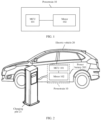
- a schematic diagram of a charging scenario of an electric vehicle is shown in FIG. 2 .
- an electric vehicle 20 includes a power battery 203 and the powertrain 10 shown in FIG. 1 .
- the power battery 203 establishes a connection to a direct current power supply by using the powertrain 10.
- a direct current power supply In FIG. 2 , an example in which the direct current power supply is a charging pile 21 is used. In some other possible implementations, the direct current power supply may be specifically another electric vehicle (not shown in the figure).
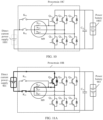
- FIG. 3 is a schematic diagram of a structure of a powertrain according to an embodiment of this application.
- a powertrain 10A is disposed between a direct current power supply 301 and a power battery 303.
- the powertrain 10A includes an MCU and a motor M3.
- the MCU includes three bridge arms and a controller (not shown in the figure).
- the three bridge arms include a first bridge arm, a second bridge arm, and a third bridge arm.
- each bridge arm may include two switch units connected in series.
- a switch unit can include at least one switch connected in series or in parallel. During specific practice, the switch unit can select, based on a voltage and a current in a power supply module, a plurality of switches connected in series or in parallel.
- the switch may be an insulated gate bipolar transistor (Insulated Gate Bipolar Transistor, IGBT) and an anti-parallel diode of the IGBT, or a metal-oxide-semiconductor field-effect transistor (Metal-Oxide-Semiconductor Field-Effect Transistor, MOSFET).
- IGBT Insulated Gate Bipolar Transistor
- MOSFET Metal-oxide-semiconductor field-effect transistor
- types and quantities of switches in the switch unit are not limited in embodiments of this application.
- the first bridge arm includes a switch tube Q 31 and a switch tube Q 32 connected in series with the switch tube Q 31 .
- the second bridge arm includes a switch tube Q 33 and a switch tube Q 34 connected in series with the switch tube Q 33 .
- the third bridge arm includes a switch tube Q 35 and a switch tube Q 36 connected in series with the switch tube Q 35 .
- first bridge arm includes the switch tube Q 33 and the switch tube Q 34 connected in series with the switch tube Q 33 .
- the second bridge arm includes the switch tube Q 35 and the switch tube Q 36 connected in series with the switch tube Q 35 .
- the third bridge arm includes the switch tube Q 31 and the switch tube Q 32 connected in series with the switch tube Q 31 .
- a first end of the direct current power supply 301 is coupled to one end of each bridge arm and a first end of the power battery 303.
- the first end of the direct current power supply 301 is a positive end
- a second end of the direct current power supply 301 is a negative end
- the first end of the power battery 303 is a positive end
- a second end of the power battery 303 is a negative end.
- the positive end of the direct current power supply 301 is coupled to a collector of the switch tube Q 31 , a collector of the switch tube Q 33 , a collector of the switch tube Q 35 , and the positive end of the power battery 303.
- the negative end of the power battery 303 is coupled to an emitter of the switch tube Q 32 , an emitter of the switch tube Q 34 , and an emitter of the switch tube Q 36 .
- the "coupling" described in this application is referred to directly or indirectly connection.
- a is coupled to B may be that A is directly connected to B, or may be that A and B are indirectly connected by using one or more other electronic components.
- A may be directly connected to C, and C is directly connected to B, so that A and B are connected by using C.
- the direct current power supply 301 may be connected to the collector of the switch tube Q 31 , the collector of the switch tube Q 33 , the collector of the switch tube Q 35 , and the positive end of the power battery 303 by using switches.
- a midpoint of each bridge arm is coupled to one end of a motor winding corresponding to each bridge arm.
- the midpoint of each bridge arm is a series coupling point between two switch units connected in series.
- an emitter of the switch tube Q 31 and a collector of the switch tube Q 32 are coupled to one end of a motor winding N U 3
- an emitter of the switch tube Q 33 and a collector of the switch tube Q 34 are coupled to one end of a motor winding N V 3
- an emitter of the switch tube Q 35 and a collector of the switch tube Q 36 are coupled to one end of a motor winding N W 3 .
- the other end of the motor winding N U 3 , the other end of the motor winding N V 3 , and the other end of the motor winding N W 3 are coupled to the negative end of the direct current power supply 301.
- the first end of the direct current power supply may be the negative end
- the second end of the direct current power supply may be the positive end
- the first end of the power battery may be the negative end
- the second end of the power battery may be the positive end (not shown in the figure).
- the positive end of the direct current power supply is coupled to the other end of each motor winding
- the negative end of the direct current power supply is coupled to the other end of each bridge arm.
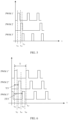
- FIG. 4 is a schematic diagram of a waveform according to an embodiment of this application.
- the controller may send a PWM1 signal to the switch tube Q 31 and send a PWM2 signal to the switch tube Q 33 .
- a rising edge of the PWM1 signal for example, is at a t 41 moment
- a rising edge of the PWM2 signal for example, is at a t 42 moment. Therefore, interleaving of the PWM1 signal and the PWM2 signal is specifically: the t 42 moment lags behind the t 41 moment for a first preset time period.
- the first preset time period is preset.
- a length of the first preset time period is related to a size of a ripple of an output current of the powertrain and the amount of heat generated by magnetic steel in the motor.
- the setting of the first preset time period may be adjusted based on specific practical applications, that is, the length of the first preset time period is not limited in this embodiment of this application.
- interleaving of the PWM1 signal and the PWM2 signal may alternatively be that a falling edge of the PWM1 signal and a falling edge of the PWM2 signal are staggered.
- the falling edge of the PWM2 signal lags behind a second preset time period relative to the falling edge of the PWM1 signal.
- the second preset time period is preset.
- a length of the second preset time period is related to a size of a ripple of an output current of the powertrain and the amount of heat generated by magnetic steel in the motor.
- the setting of the second preset time period may also be adjusted based on specific practical applications, that is, the length of the second preset time period is not limited in the embodiment of this application.
- the rising edges or the falling edges of the PWM1 signal and the PWM2 signal may be set, that is, the first preset time period is preset or the second preset time period is preset, to implement interleaving of the PWM1 signal and the PWM2 signal.
- the rising edges and the falling edges of the PWM1 signal and the PWM2 signal may be set simultaneously, that is, the first preset time period and the second preset time period are preset, to implement interleaving of the PWM1 signal and the PWM2 signal.
- a rising edge of the PWM3 signal is at the t 41 moment, that is, the rising edge of the PWM3 signal and the rising edge of the PWM1 appear simultaneously.
- the signals sent by the controller to two switch units in a same switch bridge arm are complementary. That is, a signal sent by the controller to the switch tube Q 32 and the PWM1 signal are complementary, a signal sent to the switch tube Q 34 and the PWM2 signal are complementary, and a signal sent to the switch tube Q 36 and the PWM3 signal are complementary.
- the PWM1 signal controlling the switch tube Q 31 may be referred as a first PWM signal
- the PWM2 signal controlling the switch tube Q 33 may be referred to as a second PWM signal.
- the controller controls the first PWM signal of the first bridge arm (that is, the switch tube Q 31 ) and the second PWM signal of the second bridge arm (that is, the switch tube Q 33 ) to be interleaved with each other, so that the switch tube Q 33 lags behind the switch tube Q 31 to be turned on, and then the motor winding N U 3 and the motor winding N V 3 in the powertrain are connected in parallel for less time, or even the motor winding N U 3 and the motor winding N V 3 are not connected in parallel.
- the inductance in the powertrain is larger than the inductance generated when the switch tube Q 31 and the switch tube Q 33 are turned on simultaneously, and the ripple of the output current of the powertrain is small.
- a balance between the amount of heat generated by magnetic steel in the motor and a size of a ripple of an output current of the powertrain can not only ensure that the heat of the magnetic steel in the motor falls within a safe range, but also can reduce the ripple of the output current of the powertrain.
- FIG. 5 is a schematic diagram of another waveform according to an embodiment of this application.
- the controller may send a PWM1' signal to the switch tube Q 31 , send a PWM2' signal to the switch tube Q 33 , and send a PWM3' signal to the switch tube Q 35 .
- a rising edge of the PWM1' signal for example, is at a t 51 moment
- a rising edge of PWM2' signal for example
- a rising edge of PWM3' for example, is at a t 53 moment.
- That the PWM1' signal, the PWM2' signal, the PWM3' signal are interleaved with each other is specifically: the t 52 moment lags behind the t 51 moment for a first preset time period, and the t 53 moment lags behind the t 52 moment for a third preset time period.
- the third preset time period is also preset.
- a length of the third preset time period is also related to a size of a ripple of an output current of the powertrain and the amount of heat generated by magnetic steel in the motor.
- the setting of the third preset time period may be adjusted based on specific practical applications, that is, the length of the third preset time period is not limited in this embodiment of this application.
- the PWM1' signal, the PWM2 signal, and the PWM3' signal are interleaved with each other may alternatively be specifically: a falling edge of the PWM2' signal lags behind a second preset time period relative to a falling edge of the PWM1' signal, and a falling edge of the PWM3' signal lags behind a fourth preset time period relative to a falling edge of the PWM2' signal.
- the fourth preset time period is preset.
- the fourth preset time period is related to a size of a ripple of an output current of the powertrain and the amount of heat generated by magnetic steel in the motor.
- the setting of the fourth preset time period may also be adjusted based on specific practical applications, that is, the length of the fourth preset time period is not limited in this embodiment of this application.
- the rising edges or the falling edges of the PWM1' signal, the PWM2' signal, and the PWM3' signal may be set, that is, the first preset time period and the third preset time period are preset, to implement interleaving of the PWM1' signal, the PWM2' signal, and the PWM3' signal.
- the second preset time period and the fourth preset time period are preset, to implement interleaving of the PWM1' signal, the PWM2' signal, and the PWM3' signal.
- the rising edges and the falling edges of the PWM1' signal, the PWM2' signal, and the PWM3' signal may be set simultaneously, that is, the first preset time period, the second preset time period, the third preset time period, and the fourth preset time period are preset, to implement interleaving of the PWM1' signal, the PWM2' signal, and the PWM3' signal.
- the schematic diagram of the waveform shown in this embodiment of this application specifically realizes three-phase interleaving, that is, switch tubes in the three bridge arms are not turned on simultaneously.
- the switch tube Q 33 lags behind the switch tube Q 31 to be turned on
- the switch tube Q 35 lags behind the switch tube Q 33 to be turned on.
- the inductance of the powertrain obtained through controlling in this embodiment of this application is larger, so that the ripple of the output current of the powertrain is smaller, but in this case, the amount of the heat generated by the magnetic steel of the motor is larger.
- it can also be ensured that heat generated by magnetic steel in the motor falls within a safe range, and a ripple of an output current of the powertrain is reduced.
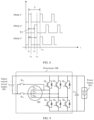
- FIG. 6 is a schematic diagram of another waveform according to an embodiment of this application.
- the controller may send a PWM1" signal to the switch tube Q 31 , send a PWM2" signal to the switch tube Q 33 , and send a PWM3" signal to the switch tube Q 35 .
- a rising edge of the PWM1" signal for example, is at a t 61 moment
- a corresponding falling edge is at a t 62 moment
- Arising edge of the PWM2" signal for example, is at a t 63 moment
- a corresponding falling edge is at a t 64 moment.
- Arising edge of the PWM3" signal is at a t 65 moment, and a corresponding falling edge is at a t 66 moment.
- Anext rising edge of the PWM1" signal is at a t 67 moment. Therefore, a time period of the PWM1" signal is a time difference (for example, T) between the t 67 moment and the t 61 moment.
- the PWM1" signal, the PWM2" signal, and the PWM3" signal are interleaved with each other is specifically: the t 63 moment lags behind the t 61 moment for a first preset time period, and the t 65 moment lags behind the t 63 moment for a third preset time period.
- the first preset time period and the third preset time period are equal, and are T/3.
- the three bridge arms are three-phase interleaved by 120°.
- the PWM1" signal, the PWM2" signal, and the PWM3" signal are interleaved with each other may alternatively be specifically: the falling edge of the PWM2" signal lags behind a second preset time period relative to the falling edge of the PWM1" signal, and the falling edge of the PWM3" signal lags behind a fourth preset time period relative to the falling edge of the PWM2" signal.
- the second preset time period and the fourth preset time period are equal, and are T/3.
- the schematic diagram of the waveform shown in this embodiment of this application specifically realizes three-phase interleaving by 120°, that is, switch tubes in the three bridge arms are not turned on simultaneously.
- the turn-on of the switch tube Q 33 lags behind the turn-on of the switch tube Q 31 for T/3
- the turn-on of the switch tube Q 35 lags behind the turn-on of the switch tube Q 33 for T/3.
- the control manner of three-phase interleaving by 120° in this embodiment of this application is more in accordance with a controlling habit of the motor, and the technical effects described in FIG. 5 may also be implemented in this embodiment of this application.
- a schematic diagram of a ripple of an output current of the powertrain may refer to FIG. 7A .
- a current of the motor winding N U 3 is I U 3
- a current of the motor winding N V 3 is I V 3
- a current of the motor winding N W 3 is I W 3 .
- the output current I O of the powertrain is a sum of the currents I U 3 , I V 3 and I W 3 .
- a ripple amplitude of a current of each motor winding is 65 A.
- a ripple amplitude of the output current I O of the powertrain may be 20 A. It may be understood that it can be seen from the schematic diagram of a ripple shown in FIG. 7A that ripple currents of the three motor windings are interleaved. In this case, peak values of ripples of the motor windings may be staggered. For example, when a ripple current of the motor winding N U 3 is large, a ripple current of the motor winding N V 3 and a ripple current of the motor winding N W 3 are small, so that a ripple of the output current of the powertrain is less than a ripple current of any motor winding.
- an embodiment of this application further provides a schematic diagram of a ripple shown in FIG. 7B .
- the controller controls the three bridge arms by using a control manner of three-phase interleaving by 60°, that is, the first preset time period and the third preset time period are equal, and are T/6.
- a current of the motor winding N U 3 is I U 3 ′
- a current of the motor winding N V 3 is I V 3 ′
- a current of the motor winding N W 3 is I W 3 ′.
- an output current I O ' of the powertrain is a sum of the currents I U 3 ′, I V 3 ′ and I W 3 ′.
- a ripple amplitude of a current of each motor winding is 65 A.
- a ripple amplitude of the output current I O ′ of the powertrain may be 95 A.
- periods of the PWM1" signal, the PWM2" signal, and the PWM3" signal are equal, that is, are all T.
- duty ratios of the PWM1" signal, the PWM2" signal, and the PWM3" signal are the same.
- the controller may generate control signals of the three bridge arms by using a same working frequency, and does not need to switch different frequencies to generate signals with different periods, which is easy to control.
- FIG. 8 is a schematic diagram of another waveform according to an embodiment of this application.
- the controller may send a PWM1′′′ signal to the switch tube Q 31 , send a PWM2′′′ signal to the switch tube Q 33 , and send a PWM3′′′ signal to the switch tube Q 35 .
- arising edge of the PWM1′′′ signal for example, is at a t 81 moment
- a corresponding falling edge is at a t 82 moment
- Arising edge of the PWM2′′′ signal for example, is at the t 81 moment
- a corresponding falling edge is at the t 82 moment.
- a time period of the PWM1′′′ signal is a time difference (for example, T) between the t 82 moment and the t 81 moment.
- Arising edge of the PWM2′′′ signal is at a t 83 moment, and a corresponding falling edge is at a t 84 . moment. It can be seen that the t 83 moment lags behind the t 81 moment for a first preset time period, and the first preset time period is T/2. In this case, two of the three bridge arms are interleaved by 180°.
- the schematic diagram of the waveform shown in this embodiment of this application specifically realizes two-phase interleaving by 180°, that is, switch tubes in two bridge arms are not turned on simultaneously.
- the switch tube Q 31 and the switch tube Q 33 are turned on simultaneously, and the switch tube Q 35 lags behind the switch tube Q 31 and the switch tube Q 33 for T/2 to be turned on. It is found by the inventor of this application in the process of research and practice that when the controller controls the three bridge arms by using the schematic diagram of the waveform shown in FIG. 8 , the amount of the heat generated by the magnetic steel of the motor is small.
- each switch tube (for example, the switch tube Q 31 , the switch tube Q 33 , and the switch tube Q 35 ) in the three bridge arms is turned on when receiving a voltage in high level, and is turned off when receiving a voltage in low level. Therefore, each switch tube may be turned on or off based on the schematic diagram of the waveform shown in FIG. 4 , FIG. 5, and FIG. 6 , so that the powertrain forms different circuit statuses, thereby increasing the voltage of the direct current power supply 301, and further providing the increased voltage to the power battery 303.
- controller controls the switch tubes in the three bridge arms by using any schematic diagram of the waveform shown in FIG. 4 to FIG. 6 , which should be understood as an example.
- the controller may further use another schematic diagram, provided that rising edges or falling edges of signals of switch tubes of any two of the three bridge arms are interleaved.
- FIG. 9 is a schematic diagram of another structure of a powertrain according to an embodiment of this application.
- a powertrain 10B is disposed between a direct current power supply 901 and a power battery 903.
- the powertrain 10B includes three bridge arms, a motor M9, a first switching switch K 91 , and a second switching switch K 92 .
- a switch included in a bridge arm is specifically an IGBT and an anti-parallel diode of the IGBT is used.
- a first bridge arm includes a switch tube Q 91 and a switch tube Q 92 connected in series with the switch tube Q 91 .
- a second bridge arm includes a switch tube Q 93 and a switch tube Q 94 connected in series with the switch tube Q 93 .
- a third bridge arm includes a switch tube Q 95 and a switch tube Q 96 connected in series with Q 95 .
- first bridge arm includes the switch tube Q 93 and the switch tube Q 94 connected in series with the switch tube Q 93 .
- the second bridge arm includes the switch tube Q 95 and the switch tube Q 96 connected in series with the switch tube Q 95 .
- the third bridge arm includes the switch tube Q 91 and the switch tube Q 92 connected in series with the switch tube Q 91 .
- the first switching switch K 91 and the second switching switch K 92 may be specifically a contactor, a relay, an IGBT, or a MOSFET.
- a first end of the direct current power supply 901 is coupled to one end of each bridge arm and a first end of the power battery 903.
- the first end of the direct current power supply 901 shown in FIG. 9 is a positive end
- a second end of the direct current power supply 901 is a negative end
- the first end of the power battery 903 is a positive end
- a second end of the power battery 903 is a negative end.
- the positive end of the direct current power supply 901 is coupled to a collector of the switch tube Q 91 , a collector of the switch tube Q 93 , a collector of the switch tube Q 95 , and the positive end of the power battery 903.
- the negative end of the power battery 903 is coupled to an emitter of the switch tube Q 92 , an emitter of the switch tube Q 94 , and an emitter of the switch tube Q 96 .
- a midpoint of each bridge arm is coupled to one end of a motor winding corresponding to each bridge arm.
- the midpoint of each bridge arm is a series coupling point between two switch units connected in series.
- an emitter of the switch tube Q 91 and a collector of the switch tube Q 92 are coupled to one end of a motor winding N U 9
- an emitter of the switch tube Q 93 and a collector of the switch tube Q 94 are coupled to one end of a motor winding N V 9
- an emitter of the switch tube Q 95 and a collector of the switch tube Q 96 are coupled to one end of a motor winding N W 9 .
- One end of the first switching switch K 91 is coupled to a midpoint of any of the three bridge arms.
- FIG. 9 uses an example in which one end of the first switching switch K 91 is coupled to the emitter of the switch tube Q 91 and the collector of the switch tube Q 92 .
- one end of the first switching switch K 91 may be coupled to the emitter of the switch tube Q 93 and the collector of the switch tube Q 94 .
- one end of the first switching switch K 91 may be coupled to the emitter of the switch tube Q 95 and the collector of the switch tube Q 96 .
- the other end of the motor winding N U 9 , the other end of the motor winding N V 9 , and the motor winding N W 9 are coupled to one end of the second switching switch K 92 .
- the other end of the second switching switch K 92 and the other end of the first switching switch K 91 are coupled to the negative end of the direct current power supply 901.
- the powertrain further includes an inductor (not shown in the figure).
- a specific connection manner of the inductor may be that one end of the inductor is coupled to the other end of the second switching switch K 92 and the other end of the first switching switch K 91 , and the other end of the inductor is coupled to the second end of the direct current power supply 901.
- FIG. 10 is a schematic diagram of another structure of a powertrain according to an embodiment of this application.
- a powertrain 10C is disposed between a direct current power supply 1001 and a power battery 1003.
- An internal structure of the powertrain 10C may refer to the powertrain 10B shown in FIG. 9 .
- the emitter of the switch tube Q 91 and the collector of the switch tube Q 92 are coupled to one end of the motor winding N U 9
- the emitter of the switch tube Q 93 and the collector of the switch tube Q 94 are coupled to one end of the motor winding N V 9
- the emitter of the switch tube Q 95 and the collector of the switch tube Q 96 are coupled to one end of the motor winding N W 9 .
- the other end of the motor winding N U 9 , the other end of the motor winding N V 9 , and the motor winding N W 9 are coupled to one end of the second switching switch K 92 , and one end of the first switching switch K 91 is coupled to the emitter of the switch tube Q 91 and the collector of the switch tube Q 92 .
- the powertrain 10C have a different manner of coupling the direct current power supply 1001 outward.
- a first end of the direct current power supply 1001 is a negative end
- a second end of the direct current power supply 1001 is a positive end
- a first end of the power battery 1003 is a negative end
- a second end of the power battery 1003 is a positive end.
- the positive end of the direct current power supply 1001 is coupled to the other end of the second switching switch K 92 and the other end of the first switching switch K 91
- the negative end of the direct current power supply 1001 is coupled to the collector of the switch tube Q 92 , the collector of the switch tube Q 94 , the collector of the switch tube Q 96 , and the positive end of the power battery 1003.
- the positive end of the power battery 1003 is coupled to the collector of the switch tube Q 91 , the collector of the switch tube Q 93 , and the collector of the switch tube Q 95 .
- the powertrain 10B shown in FIG. 9 is used as an example below to describe a circuit status of the powertrain.
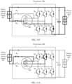
- the controller controls the second switching switch K 92 to be turned on, and the controller sends a signal to each bridge arm based on the waveform shown in FIG. 6 . That is, the controller may send the PWM1" signal to the switch tube Q 31 , send the PWM2" signal to the switch tube Q 33 , and send the PWM3" signal to the switch tube Q 35 .
- the switch tube Q 91 is turned on, the switch tube Q 93 and the switch tube Q 95 are turned on, and the second switching switch K 92 is turned on.
- the powertrain 10B forms a circuit status shown in FIG. 11A .
- the direct current power supply 901 charges the motor winding N U 9 through the switch tube Q 91 .
- the switch tube Q 91 , the switch tube Q 93 , and the switch tube Q 95 are turned off, and the second switching switch K 92 is turned on.
- the powertrain 10B forms a circuit status shown in FIG. 11B .
- the direct current power supply 901 and the motor winding N U 9 are discharged jointly, and a voltage of two ends of the power battery 903 is a sum of a voltage of the direct current power supply 901 and a voltage of the motor winding N U 9 , thereby increasing the voltage of the direct current power supply 901, and further providing the increased voltage to the power battery 903.
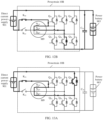
- the switch tube Q 93 is turned on, the switch tube Q 91 and the switch tube Q 95 are turned off, and the second switching switch K 92 is turned on.
- the powertrain 10B forms a circuit status shown in FIG. 11C .
- the direct current power supply 901 charges the motor winding N V 9 through the switch tube Q 93 .
- the switch tube Q 91 , the switch tube Q 93 , and the switch tube Q 95 are turned off, and the second switching switch K 92 is turned on.
- the powertrain 10B forms a circuit status shown in FIG. 11D .
- the direct current power supply 901 and the motor winding N V 9 are discharged jointly, and a voltage of two ends of the power battery 903 is a sum of a voltage of the direct current power supply 901 and a voltage of the motor winding N V 9 , thereby increasing the voltage of the direct current power supply 901, and further providing the increased voltage to the power battery 903.
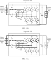
- the switch tube Q 95 is turned on, the switch tube Q 91 and the switch tube Q 93 are turned off, and the second switching switch K 92 is turned on.
- the powertrain 10B forms a circuit status shown in FIG. 11E .
- the direct current power supply 901 charges the motor winding N W 9 through the switch tube Q 95 .
- the switch tube Q 91 , the switch tube Q 93 , and the switch tube Q 95 are turned off, and the second switching switch K 92 is turned on.
- the powertrain 10B forms a circuit status shown in FIG. 11F .
- the direct current power supply 901 and the motor winding N W 9 are discharged jointly, and a voltage of two ends of the power battery 903 is a sum of a voltage of the direct current power supply 901 and a voltage of the motor winding N W 9 , thereby increasing the voltage of the direct current power supply 901, and further providing the increased voltage to the power battery 903.
- FIG. 11A to FIG. 11F are all circuit statuses that can be formed by the powertrain 10B in a case in which the second switching switch K 92 is turned on and the first switching switch K 91 is turned off.
- the first switching switch K 91 when a difference between a voltage of the power battery 903 and a voltage of the direct current power supply 901 is less than a first preset threshold, the first switching switch K 91 is turned off, and the second switching switch K 92 is turned on.
- the first preset threshold is an experienced value, such as 100 V or 150 V.
- the controller before sending a PWM signal to each switch tube, the controller detects the voltage of the direct current power supply 901 and the voltage of the power battery 903. For example, when the controller detects that the voltage of the direct current power supply 901 is 500 V, the voltage of the power battery 903 is 600 V, and the first preset threshold is 150 V, the controller controls the first switching switch K 91 to be turned off, and the second switching switch K 92 to be turned on. In another example, after the controller sends a PWM signal to each switch tube, the power battery 903 is in a charging status, and the controller still detects the voltage of the power battery 903 in real time during charging.
- the controller continues to control the first switching switch K 91 to be turned off, and the second switching switch K 92 to be turned on.
- the controller controls the first switching switch K 91 to be turned on, and the second switching switch K 92 to be turned off.
- the first switching switch K 91 when a difference between a voltage of the power battery 903 and a voltage of the direct current power supply 901 is greater than or equal to a first preset threshold, the first switching switch K 91 is turned on, and the second switching switch K 92 is turned off.
- the controller may send a fourth PWM signal to the switch tube Q 93 , and send a fifth PWM signal to the switch tube Q 95 .
- the switch tube Q 91 is in a turn-off status. It may be understood that the controller may send a voltage in low level to the switch tube Q 91 , to enable the switch tube Q 91 to be turned off. Alternatively, the controller does not control the switch tube Q 91 , and a default status of the switch tube Q 91 is a turn-off status.
- fourth PWM signal and the fifth PWM signal may be synchronized signals, or rising edges or falling edges of the two signals may be interleaved.
- the fourth PWM signal and the fifth PWM signal are not limited in this embodiment of this application.
- the powertrain 10B may have a plurality of circuit statuses.
- the switch tube Q 93 is turned on, the switch tube Q 95 is turned off, and the first switching switch K 91 is turned on.
- the powertrain 10B may form a circuit status shown in FIG. 12A .
- the direct current power supply 901 charges the motor winding N V 9 and the motor winding N U 9 through the switch tube Q 93 .
- the switch tube Q 93 and the switch tube Q 95 are turned off, and the first switching switch K 91 is turned on.
- the powertrain 10B may form a circuit status shown in FIG. 12B .
- the direct current power supply 901, the motor winding N V 9 , and the motor winding N U 9 are discharged jointly, and a voltage of two ends of the power battery 903 is a sum of a voltage of the direct current power supply 901 and voltages of the motor winding N U 9 and the motor winding N V 9 , thereby increasing the voltage of the direct current power supply 901, and further providing the increased voltage to the power battery 903.
- the switch tube Q 95 is turned on, the switch tube Q 93 is turned off, and the first switching switch K 91 is turned on.
- the powertrain 10B may form a circuit status shown in FIG. 13A .
- the direct current power supply 901 charges the motor winding N W 9 and the motor winding N U 9 through the switch tube Q 95 .
- the switch tube Q 93 and the switch tube Q 95 are turned off, and the first switching switch K 91 is turned on.
- the powertrain 10B may form a circuit status shown in FIG. 13B .
- the direct current power supply 901, the motor winding N W 9 , and the motor winding N U 9 are discharged jointly, and a voltage of two ends of the power battery 903 is a sum of a voltage of the direct current power supply 901 and voltages of the motor winding N U 9 and the motor winding N W 9 , thereby increasing the voltage of the direct current power supply 901, and further providing the increased voltage to the power battery 903.
- the switch tube Q 93 and the switch tube Q 95 are turned on, and the first switching switch K 91 is turned on.
- the powertrain 10B may form a circuit status shown in FIG. 14A .
- the direct current power supply 901 charges the motor winding N V 9 and the motor winding N U 9 through the switch tube Q 93 , and the direct current power supply 901 further charges the motor winding N W 9 and the motor winding N U 9 through the switch tube Q 95 .
- the switch tube Q 93 and the switch tube Q 95 are turned on, and the first switching switch K 91 is turned on.
- the powertrain 10B may form a circuit status shown in FIG. 14B .
- the direct current power supply 901, the motor winding N U 9 , and the motor winding N V 9 are discharged jointly, and the direct current power supply 901, the motor winding N U 9 , and the motor winding N W 9 are discharged jointly.
- a sum of a voltage of two ends when the motor winding N V 9 and the motor winding N W 9 are connected in parallel, a voltage of two ends of the motor winding N U 9 , and a voltage of two ends of the direct current power supply 901 is a voltage of two ends of the power battery 903.
Landscapes
- Engineering & Computer Science (AREA)
- Power Engineering (AREA)
- Transportation (AREA)
- Mechanical Engineering (AREA)
- Life Sciences & Earth Sciences (AREA)
- Sustainable Development (AREA)
- Sustainable Energy (AREA)
- Electric Propulsion And Braking For Vehicles (AREA)
- Dc-Dc Converters (AREA)
- Inverter Devices (AREA)
Abstract
Description
- This application relates to the field of new energy vehicle technologies, and in particular, to a powertrain, a charging control method, and an electric vehicle.
- Output voltages of some charging piles on an existing market range from 220 V to 500 V. To resolve a problem of a slow charging speed of an electric vehicle, a voltage of a power battery equipped on the current electric vehicle is high, for example, 600 V to 800 V. Therefore, when the voltage of the power battery on the electric vehicle is 600 V, a charging pile that can only output a voltage ranging from 220 V to 500 V cannot charge the electric vehicle. Therefore, to adapt to the some charging piles on the existing market, a bridge arm and a motor winding used to drive a motor in the electric vehicle can be reused, to increase the voltages output by the charging piles, and further provide increased voltages to the power battery. In this case, how to specifically control turn-no or turn-off of the bridge arm is a key research issue at present.
- This application provides a powertrain, a charging control method, and an electric vehicle, which can ensure that heat generated by magnetic steel in a motor falls within a safe range, and reduce a ripple of an output current of the powertrain.
- According to a first aspect, an embodiment of this application provides a powertrain. The powertrain is disposed between a direct current power supply and a power battery, the powertrain includes a motor control unit (Motor Control Unit, MCU) and a motor, the MCU includes three bridge arms and a controller, and the motor includes three motor windings corresponding to the three bridge arms. In specific implementation, a first endof the direct current power supply is coupled to one end of each of the three bridge arms and a first end of the power battery, and a second end of the power battery is coupled to the other end of each bridge arm. A midpoint of each bridge arm is coupled to one end of a motor winding corresponding to each bridge arm, and the other end of each of the three motor windings is coupled to a second end of the direct current power supply. The three bridge arms include a first bridge arm and a second bridge arm. The first bridge arm may be turned on or off based on a first pulse width modulation (Pulse Width Modulation, PWM) signal sent by the controller, and the second bridge arm may be turned on or off based on a second PWM signal sent by the controller. The first PWM signal and the second PWM signal are interleaved, that is, a rising edge of the second PWM signal lags behind a first preset time period relative to a rising edge of the first PWM signal, or a falling edge of the second PWM signal lags behind a second preset time period relative to a falling edge of the first PWM signal. In the embodiment of this application, the first PWM signal and the second PWM signal are controlled to be interleaved, to balance the amount of heat generated by magnetic steel in the motor and a size of a ripple of an output current of the powertrain, thereby not only ensuring that the heat generated by the magnetic steel in the motor falls within a safe range, but also reducing the ripple of the output current of the powertrain.
- With reference to the first aspect, in a first possible implementation, the three bridge arms further include a third bridge arm. The third bridge arm may be turned on or off based on a third PWM signal. Arising edge of the third PWM signal lags behind a third preset time period relative to the rising edge of the second PWM signal, or a falling edge of the third PWM signal lags behind a fourth preset time period relative to the falling edge of the second PWM signal. Three-phase interleaving is specifically implemented in the embodiment of this application, that is, the three bridge arms are not turned on or off simultaneously. According to the embodiment of this application, it can also be ensured that heat generated by magnetic steel in the motor falls within a safe range, and a ripple of an output current of the powertrain is reduced.
- With reference to the first possible implementation of the first aspect, in a second possible implementation, a time period of the first PWM signal is T, and the first preset time period and the third preset time period are T/3, or the second preset time period and the fourth preset time period are T/3. The control manner of three-phase interleaving by 120° according to the embodiment of this application is more in accordance with a control habit of the motor, which can also ensure that heat generated by magnetic steel in the motor falls within a safe range, and reduce a ripple of an output current of the powertrain.
- With reference to the first aspect, in a third possible implementation, the three bridge arms further include a third bridge arm. The third bridge arm may be turned on or off based on a third PWM signal. A rising edge of the third PWM signal and the rising edge of the first PWM signal appear simultaneously, and a falling edge of the third PWM signal and the falling edge of the first PWM signal appear simultaneously.
- With reference to the third possible implementation of the first aspect, in a fourth possible implementation, a time period of the first PWM signal is T, and the first preset time period is T/2, or the second preset time period is T/2.
- With reference to any one of the possible implementations of the first aspect, in a fifth possible implementation, the first PWM signal, the second PWM signal, and the third PWM signal have a same time period and duty ratio.
- With reference to the first aspect or any one of the possible implementations of the first aspect, in a sixth possible implementation, the powertrain further includes a first switching switch and a second switching switch. One end of the first switching switch is coupled to a midpoint of any of the three bridge arms.
- That the other end of each of the three motor windings is coupled to a second end of the direct current power supply is specifically: the other end of each of the three motor windings is coupled to one end of the second switching switch, and the other end of the second switching switch and the other end of first switching switch are coupled to the second end of the direct current power supply.
- With reference to the sixth possible implementation of the first aspect, in a seventh possible implementation, when a difference between a voltage of the power battery and a voltage of the direct current power supply is less than a first preset threshold, the first switching switch is turned off, and the second switching switch is turned on.
- With reference to the sixth possible implementation of the first aspect, in an eighth possible implementation, when a difference between a voltage of the power battery and a voltage of the direct current power supply is greater than or equal to a first preset threshold, the first switching switch is turned on, and the second switching switch is turned off.
- That the first bridge arm is turned on or off based on a first pulse width modulation (Pulse Width Modulation, PWM) signal, and the second bridge arm is turned on or off based on a second PWM signal is specifically:
other two bridge arms in the three bridge arms other than the bridge arm coupled to the first switching switch are respectively turned on or off based on a fourth PWM signal and a fifth PWM signal. - With reference to the sixth possible implementation of the first aspect, in a ninth possible implementation, the powertrain further includes an inductor. That the other end of the second switching switch and the other end of the first switching switch are coupled to the second end of the direct current power supply is specifically: the other end of the second switching switch and the other end of the first switching switch are coupled to one end of the inductor, and the other end of the inductor is coupled to the second end of the direct current power supply.
- According to a second aspect, an embodiment of this application provides a charging control method. The charging control method is applied to a powertrain, and the powertrain includes a motor control unit (Motor Control Unit, MCU) and a motor. The MCU includes three bridge arms and a controller, and the motor includes three motor windings corresponding to the three bridge arms. In specific implementation, a first end of the direct current power supply is coupled to one end of each of the three bridge arms and a first end of a power battery, and a second end of the power battery is coupled to the other end of each bridge arm. A midpoint of each bridge arm is coupled to one end of a motor winding corresponding to each bridge arm, and the other end of each of the three motor windings is coupled to a second end of the direct current power supply. The three bridge arms include a first bridge arm and a second bridge arm.
- The charging control method is specifically: sending, by the controller, a first pulse width modulation (Pulse Width Modulation, PWM) signal to the first bridge arm, and sending a second PWM signal to the second bridge arm. The first PWM signal and the second PWM signal are interleaved, that is, a rising edge of the second PWM signal lags behind a first preset time period relative to a rising edge of the first PWM signal, or a falling edge of the second PWM signal lags behind a second preset time period relative to a falling edge of the first PWM signal.
- With reference to the second aspect, in a first possible implementation, the three bridge arms further include a third bridge arm. The charging control method further includes: sending, by the controller, a third PWM signal to the third bridge arm. A rising edge of the third PWM signal lags behind a third preset time period relative to the rising edge of the second PWM signal, or a falling edge of the third PWM signal lags behind a fourth preset time period relative to the falling edge of the second PWM signal.
- With reference to the first possible implementation of the second aspect, in a second possible implementation, a time period of the first PWM signal is T, and the first preset time period and the third preset time period are T/3, or the second preset time period and the fourth preset time period are T/3.
- With reference to the second aspect, in a third possible implementation, the three bridge arms further include a third bridge arm. The charging control method further includes: sending, by the controller, a third PWM signal to the third bridge arm. Arising edge of the third PWM signal and the rising edge of the first PWM signal appear simultaneously, and a falling edge of the third PWM signal and the falling edge of the first PWM signal appear simultaneously.
- With reference to the third possible implementation of the second aspect, in a fourth possible implementation, a time period of the first PWM signal is T, and the first preset time period is T/2, or the second preset time period is T/2.
- With reference to any one of the possible implementations of the second aspect, in a fifth possible implementation, the first PWM signal, the second PWM signal, and the third PWM signal have a same time period and duty ratio.
- With reference to the second aspect or any one of the possible implementations of the second aspect, in a sixth possible implementation, the powertrain further includes a first switching switch and a second switching switch.
- The charging control method further includes:
when a difference between a voltage of the power battery and a voltage of the direct current power supply is less than a first preset threshold, controlling, by the controller, the first switching switch to be turned off, and controlling the second switching switch to be turned on. One end of the first switching switch is coupled to a midpoint of any of the three bridge arms, and the other end of the first switching switch is coupled to the second end of the direct current power supply. One end of the second switching switch is coupled to the other end of each of the three motor windings, and the other end of the second switching switch is coupled to the second end of the direct current power supply. - With reference to the sixth possible implementation of the second aspect, in an eighth possible implementation, when a difference between a voltage of the power battery and a voltage power supply is greater than or equal to a first preset threshold, the controller controls the first switching switch to be turned on, and controls the second switching switch to be turned off. The controller further sends a fourth PWM signal and a fifth PWM signal respectively to other two bridge arms in the three bridge arms other than the bridge arm coupled to the first switching switch.
- According to a third aspect, an embodiment of this application provides an electric vehicle. The electric vehicle includes a power battery and the powertrain with reference to the first aspect or any of the possible implementations of the first aspect.
- It should be understood that mutual reference may be made between implementations and beneficial effects of the foregoing aspects in this application.
-
-
FIG. 1 is a schematic diagram of a structure of a powertrain according to an embodiment of this application; -
FIG. 2 is a schematic diagram of a charging scenario of an electric vehicle according to an embodiment of this application; -
FIG. 3 is a schematic diagram of a structure of a powertrain according to an embodiment of this application; -
FIG. 4 is a schematic diagram of a waveform according to an embodiment of this application; -
FIG. 5 is a schematic diagram of another waveform according to an embodiment of this application; -
FIG. 6 is a schematic diagram of another waveform according to an embodiment of this application; -
FIG. 7A and theFIG. 7B are schematic diagrams of a current ripple according to an embodiment of this application; -
FIG. 8 is a schematic diagram of another waveform according to an embodiment of this application; -
FIG. 9 is a schematic diagram of another structure of a powertrain according to an embodiment of this application; -
FIG. 10 is a schematic diagram of another structure of a powertrain according to an embodiment of this application; -
FIG. 11A to FIG. 11F are schematic diagrams of a circuit status of a powertrain according to an embodiment of this application; -
FIG. 12A andFIG. 12B are schematic diagrams of another circuit status of a powertrain according to an embodiment of this application; -
FIG. 13A andFIG. 13B are schematic diagrams of another circuit status of a powertrain according to an embodiment of this application; and -
FIG. 14A andFIG. 14B are schematic diagrams of another circuit status of a powertrain according to an embodiment of this application. - The following clearly describes the technical solutions in embodiments of this application with reference to the accompanying drawings in embodiments of this application. It is clear that the described embodiments are some but not all of embodiments of this application. All other embodiments obtained by a person of ordinary skill in the art based on embodiments of this application without creative efforts shall fall within the protection scope of this application.
- The technical solutions of this application are further described below in detail with reference to the accompanying drawings.
-
FIG. 1 is a schematic diagram of a structure of a powertrain according to an embodiment of this application. As shown inFIG. 1 , thepowertrain 10 includes a motor control unit (Motor Control Unit, MCU) 101 and amotor 102. - The
MCU 101 includes three bridge arms and a controller. The controller may send pulse width modulation (Pulse Width Modulation, PWM) signals to the three bridge arms. The three bridge arms may be turned on or off respectively based on the received PWM signals. - For example, the controller may be, for example, a central processing unit (central processing unit, CPU), another general purpose processor, a digital signal processor (digital signal processor, DSP), an application-specific integrated circuit (application-specific integrated circuit, ASIC), a field programmable gate array (field programmable gate array, FPGA) or another programmable logic device, a discrete gate or a transistor logic device, or a discrete hardware component.
- In some possible implementations, the three bridge arms and the controller are welded in a body of a same printed circuit board (Printed Circuit Board, PCB) or bodies of different PCBs. The PCB may be specifically disposed inside a hardware box. The hardware box is disposed on the top of the motor.
- The
powertrain 10 may be integrated as a whole and disposed in an electric vehicle. In this case, a schematic diagram of a charging scenario of an electric vehicle is shown inFIG. 2 . As shown inFIG. 2 , anelectric vehicle 20 includes apower battery 203 and thepowertrain 10 shown inFIG. 1 . - The
power battery 203 establishes a connection to a direct current power supply by using thepowertrain 10. InFIG. 2 , an example in which the direct current power supply is a chargingpile 21 is used. In some other possible implementations, the direct current power supply may be specifically another electric vehicle (not shown in the figure). - The following describes a specific structure of the powertrain provided in embodiments of this application with reference to the accompanying drawings.
- In some possible implementations,
FIG. 3 is a schematic diagram of a structure of a powertrain according to an embodiment of this application. As shown inFIG. 3 , apowertrain 10A is disposed between a directcurrent power supply 301 and apower battery 303. Thepowertrain 10A includes an MCU and a motor M3. - The MCU includes three bridge arms and a controller (not shown in the figure). The three bridge arms include a first bridge arm, a second bridge arm, and a third bridge arm. It should be noted that each bridge arm may include two switch units connected in series. A switch unit can include at least one switch connected in series or in parallel. During specific practice, the switch unit can select, based on a voltage and a current in a power supply module, a plurality of switches connected in series or in parallel. The switch may be an insulated gate bipolar transistor (Insulated Gate Bipolar Transistor, IGBT) and an anti-parallel diode of the IGBT, or a metal-oxide-semiconductor field-effect transistor (Metal-Oxide-Semiconductor Field-Effect Transistor, MOSFET). In general, types and quantities of switches in the switch unit are not limited in embodiments of this application.
- For example, an example in which a switch included in a bridge arm is specifically the IGBT and the anti-parallel diode of the IGBT is used. As shown in
FIG. 3 , the first bridge arm includes a switch tube Q 31 and a switch tube Q 32 connected in series with the switch tube Q 31. The second bridge arm includes a switch tube Q 33 and a switch tube Q 34 connected in series with the switch tube Q 33. The third bridge arm includes a switch tube Q 35 and a switch tube Q 36 connected in series with the switch tube Q 35. - It should be noted that the first bridge arm, the second bridge arm, and the third bridge arm may be interchangeable. For example, the first bridge arm includes the switch tube Q 33 and the switch tube Q 34 connected in series with the switch tube Q 33. The second bridge arm includes the switch tube Q 35 and the switch tube Q 36 connected in series with the switch tube Q 35. The third bridge arm includes the switch tube Q 31 and the switch tube Q 32 connected in series with the switch tube Q 31.
- In specific implementation, a first end of the direct
current power supply 301 is coupled to one end of each bridge arm and a first end of thepower battery 303. In this case, as shown inFIG. 3 , the first end of the directcurrent power supply 301 is a positive end, a second end of the directcurrent power supply 301 is a negative end, the first end of thepower battery 303 is a positive end, and a second end of thepower battery 303 is a negative end. - In this case, the positive end of the direct
current power supply 301 is coupled to a collector of the switch tube Q 31, a collector of the switch tube Q 33, a collector of the switch tube Q 35, and the positive end of thepower battery 303. The negative end of thepower battery 303 is coupled to an emitter of the switch tube Q 32, an emitter of the switch tube Q 34, and an emitter of the switch tube Q 36. - It should be noted that the "coupling" described in this application is referred to directly or indirectly connection. For example, that A is coupled to B may be that A is directly connected to B, or may be that A and B are indirectly connected by using one or more other electronic components. For example, A may be directly connected to C, and C is directly connected to B, so that A and B are connected by using C. For example, the direct
current power supply 301 may be connected to the collector of the switch tube Q 31, the collector of the switch tube Q 33, the collector of the switch tube Q 35, and the positive end of thepower battery 303 by using switches. - A midpoint of each bridge arm is coupled to one end of a motor winding corresponding to each bridge arm. The midpoint of each bridge arm is a series coupling point between two switch units connected in series. In this case, an emitter of the switch tube Q 31 and a collector of the switch tube Q 32 are coupled to one end of a motor winding N U3 , an emitter of the switch tube Q 33 and a collector of the switch tube Q 34 are coupled to one end of a motor winding N V3 , and an emitter of the switch tube Q 35 and a collector of the switch tube Q 36 are coupled to one end of a motor winding N W3.
- The other end of the motor winding N U3, the other end of the motor winding N V3, and the other end of the motor winding N W3 are coupled to the negative end of the direct
current power supply 301. - Optionally, in some possible implementations, the first end of the direct current power supply may be the negative end, the second end of the direct current power supply may be the positive end, the first end of the power battery may be the negative end, and the second end of the power battery may be the positive end (not shown in the figure). In this case, the positive end of the direct current power supply is coupled to the other end of each motor winding, and the negative end of the direct current power supply is coupled to the other end of each bridge arm.
- How to specifically control the powertrain provided in this embodiment of this application is used as an example for description below with reference to the accompanying drawings.
- In some possible implementations,
FIG. 4 is a schematic diagram of a waveform according to an embodiment of this application. As shown inFIG. 4 , the controller may send a PWM1 signal to the switch tube Q 31 and send a PWM2 signal to the switch tube Q 33. In this case, a rising edge of the PWM1 signal, for example, is at a t 41 moment, a rising edge of the PWM2 signal, for example, is at a t 42 moment. Therefore, interleaving of the PWM1 signal and the PWM2 signal is specifically: the t 42 moment lags behind the t 41 moment for a first preset time period. - The first preset time period is preset. A length of the first preset time period is related to a size of a ripple of an output current of the powertrain and the amount of heat generated by magnetic steel in the motor. The setting of the first preset time period may be adjusted based on specific practical applications, that is, the length of the first preset time period is not limited in this embodiment of this application.
- Certainly, interleaving of the PWM1 signal and the PWM2 signal may alternatively be that a falling edge of the PWM1 signal and a falling edge of the PWM2 signal are staggered. For example, the falling edge of the PWM2 signal lags behind a second preset time period relative to the falling edge of the PWM1 signal. Similarly, the second preset time period is preset. A length of the second preset time period is related to a size of a ripple of an output current of the powertrain and the amount of heat generated by magnetic steel in the motor. The setting of the second preset time period may also be adjusted based on specific practical applications, that is, the length of the second preset time period is not limited in the embodiment of this application.
- It should be noted that in specific practical applications, the rising edges or the falling edges of the PWM1 signal and the PWM2 signal may be set, that is, the first preset time period is preset or the second preset time period is preset, to implement interleaving of the PWM1 signal and the PWM2 signal. Alternatively, the rising edges and the falling edges of the PWM1 signal and the PWM2 signal may be set simultaneously, that is, the first preset time period and the second preset time period are preset, to implement interleaving of the PWM1 signal and the PWM2 signal.
- For example, an example in which the controller sends a PWM3 signal to the switch tube Q 35 is used in
FIG. 4 . A rising edge of the PWM3 signal, for example, is at the t 41 moment, that is, the rising edge of the PWM3 signal and the rising edge of the PWM1 appear simultaneously. - It may be understood that the signals sent by the controller to two switch units in a same switch bridge arm are complementary. That is, a signal sent by the controller to the switch tube Q 32 and the PWM1 signal are complementary, a signal sent to the switch tube Q 34 and the PWM2 signal are complementary, and a signal sent to the switch tube Q 36 and the PWM3 signal are complementary. In this case, in this embodiment of this application, the PWM1 signal controlling the switch tube Q 31 may be referred as a first PWM signal, and the PWM2 signal controlling the switch tube Q 33 may be referred to as a second PWM signal.
- When the switch tube Q 31 and the switch tube Q 33 are turned on simultaneously, the motor winding N U3 and the motor winding N V3 are connected in parallel, so that the inductance in the powertrain is reduced, thereby increasing a ripple of an output current of the powertrain. In this embodiment of this application, the controller controls the first PWM signal of the first bridge arm (that is, the switch tube Q 31) and the second PWM signal of the second bridge arm (that is, the switch tube Q 33) to be interleaved with each other, so that the switch tube Q 33 lags behind the switch tube Q 31 to be turned on, and then the motor winding N U3 and the motor winding N V3 in the powertrain are connected in parallel for less time, or even the motor winding N U3 and the motor winding N V3 are not connected in parallel. In this case, the inductance in the powertrain is larger than the inductance generated when the switch tube Q 31 and the switch tube Q 33 are turned on simultaneously, and the ripple of the output current of the powertrain is small.
- In general, in this embodiment of this application, a balance between the amount of heat generated by magnetic steel in the motor and a size of a ripple of an output current of the powertrain can not only ensure that the heat of the magnetic steel in the motor falls within a safe range, but also can reduce the ripple of the output current of the powertrain.
- Optionally, in some possible implementations,
FIG. 5 is a schematic diagram of another waveform according to an embodiment of this application. As shown inFIG. 5 , the controller may send a PWM1' signal to the switch tube Q 31, send a PWM2' signal to the switch tube Q 33, and send a PWM3' signal to the switch tube Q 35. In this case, a rising edge of the PWM1' signal, for example, is at a t 51 moment, a rising edge of PWM2' signal for example, is at a t 52 moment, and a rising edge of PWM3', for example, is at a t 53 moment. - That the PWM1' signal, the PWM2' signal, the PWM3' signal are interleaved with each other is specifically: the t 52 moment lags behind the t 51 moment for a first preset time period, and the t 53 moment lags behind the t 52 moment for a third preset time period. The third preset time period is also preset. A length of the third preset time period is also related to a size of a ripple of an output current of the powertrain and the amount of heat generated by magnetic steel in the motor. The setting of the third preset time period may be adjusted based on specific practical applications, that is, the length of the third preset time period is not limited in this embodiment of this application.
- Certainly, that the PWM1' signal, the PWM2 signal, and the PWM3' signal are interleaved with each other may alternatively be specifically: a falling edge of the PWM2' signal lags behind a second preset time period relative to a falling edge of the PWM1' signal, and a falling edge of the PWM3' signal lags behind a fourth preset time period relative to a falling edge of the PWM2' signal. Similarly, the fourth preset time period is preset. The fourth preset time period is related to a size of a ripple of an output current of the powertrain and the amount of heat generated by magnetic steel in the motor. The setting of the fourth preset time period may also be adjusted based on specific practical applications, that is, the length of the fourth preset time period is not limited in this embodiment of this application.
- It should be noted that in specific practical applications, the rising edges or the falling edges of the PWM1' signal, the PWM2' signal, and the PWM3' signal may be set, that is, the first preset time period and the third preset time period are preset, to implement interleaving of the PWM1' signal, the PWM2' signal, and the PWM3' signal. Alternatively, the second preset time period and the fourth preset time period are preset, to implement interleaving of the PWM1' signal, the PWM2' signal, and the PWM3' signal. Alternatively, the rising edges and the falling edges of the PWM1' signal, the PWM2' signal, and the PWM3' signal may be set simultaneously, that is, the first preset time period, the second preset time period, the third preset time period, and the fourth preset time period are preset, to implement interleaving of the PWM1' signal, the PWM2' signal, and the PWM3' signal.
- The schematic diagram of the waveform shown in this embodiment of this application specifically realizes three-phase interleaving, that is, switch tubes in the three bridge arms are not turned on simultaneously. For example, the switch tube Q 33 lags behind the switch tube Q 31 to be turned on, and the switch tube Q 35 lags behind the switch tube Q 33 to be turned on. Compared to controlling the three bridge arms by using the schematic diagram of the waveform shown in
FIG. 4 , the inductance of the powertrain obtained through controlling in this embodiment of this application is larger, so that the ripple of the output current of the powertrain is smaller, but in this case, the amount of the heat generated by the magnetic steel of the motor is larger. In general, according to this embodiment of this application, it can also be ensured that heat generated by magnetic steel in the motor falls within a safe range, and a ripple of an output current of the powertrain is reduced. - Optionally, in some possible implementations,
FIG. 6 is a schematic diagram of another waveform according to an embodiment of this application. As shown inFIG. 6 , the controller may send a PWM1" signal to the switch tube Q 31, send a PWM2" signal to the switch tube Q 33, and send a PWM3" signal to the switch tube Q 35. In this case, a rising edge of the PWM1" signal, for example, is at a t 61 moment, a corresponding falling edge is at a t 62 moment. Arising edge of the PWM2" signal, for example, is at a t 63 moment, and a corresponding falling edge is at a t 64 moment. Arising edge of the PWM3" signal, for example, is at a t 65 moment, and a corresponding falling edge is at a t 66 moment. Anext rising edge of the PWM1" signal is at a t 67 moment. Therefore, a time period of the PWM1" signal is a time difference (for example, T) between the t 67 moment and the t 61 moment. - That the PWM1" signal, the PWM2" signal, and the PWM3" signal are interleaved with each other is specifically: the t 63 moment lags behind the t 61 moment for a first preset time period, and the t 65 moment lags behind the t 63 moment for a third preset time period. Compared to the schematic diagram of the waveform shown in
FIG. 5 , in this embodiment of this application, the first preset time period and the third preset time period are equal, and are T/3. In this case, the three bridge arms are three-phase interleaved by 120°. - Certainly, that the PWM1" signal, the PWM2" signal, and the PWM3" signal are interleaved with each other may alternatively be specifically: the falling edge of the PWM2" signal lags behind a second preset time period relative to the falling edge of the PWM1" signal, and the falling edge of the PWM3" signal lags behind a fourth preset time period relative to the falling edge of the PWM2" signal. In this case, the second preset time period and the fourth preset time period are equal, and are T/3.
- The schematic diagram of the waveform shown in this embodiment of this application specifically realizes three-phase interleaving by 120°, that is, switch tubes in the three bridge arms are not turned on simultaneously. For example, the turn-on of the switch tube Q 33 lags behind the turn-on of the switch tube Q 31 for T/3, and the turn-on of the switch tube Q 35 lags behind the turn-on of the switch tube Q 33 for T/3. Compared to controlling the three bridge arms by using the schematic diagram of the waveform shown in
FIG. 5 , the control manner of three-phase interleaving by 120° in this embodiment of this application is more in accordance with a controlling habit of the motor, and the technical effects described inFIG. 5 may also be implemented in this embodiment of this application. - In this case, a schematic diagram of a ripple of an output current of the powertrain may refer to
FIG. 7A . As shown inFIG. 7A , a current of the motor winding N U3 is I U3, a current of the motor winding N V3 is I V3, and a current of the motor winding N W3 is I W3. In a case in which the three bridge arms are three-phase interleaved by 120°, the currents I U3, I V3, and I W3 are also interleaved by 120°. Therefore, at any t 71 moment, the output current IO of the powertrain is a sum of the currents I U3, I V3 and I W3. For example, a ripple amplitude of a current of each motor winding is 65 A. A ripple amplitude of the output current IO of the powertrain may be 20 A. It may be understood that it can be seen from the schematic diagram of a ripple shown inFIG. 7A that ripple currents of the three motor windings are interleaved. In this case, peak values of ripples of the motor windings may be staggered. For example, when a ripple current of the motor winding N U3 is large, a ripple current of the motor winding N V3 and a ripple current of the motor winding N W3 are small, so that a ripple of the output current of the powertrain is less than a ripple current of any motor winding. - Assuming that signals of the three bridge arms are synchronized, the currents I U3, I V3 and I W3 are also synchronized, and peak values of ripples of the motor windings appear simultaneously, so that a ripple amplitude of the output current of the powertrain is 3 ∗ 65 = 195 A. In this case, the ripple of the output current of the powertrain is large.
- To describe an effect of the three-phase interleaved control manner with different angles on a size of the ripple of the output current of the powertrain, an embodiment of this application further provides a schematic diagram of a ripple shown in
FIG. 7B . In the schematic diagram of a current ripple shown inFIG. 7B , the controller controls the three bridge arms by using a control manner of three-phase interleaving by 60°, that is, the first preset time period and the third preset time period are equal, and are T/6. In this case, as shown inFIG. 7B , a current of the motor winding N U3 is I U3′, a current of the motor winding N V3 is I V3′, and a current of the motor winding N W3 is I W3′. Therefore, at any t 81 moment, an output current IO' of the powertrain is a sum of the currents I U3′, I V3′ and I W3′. For example, a ripple amplitude of a current of each motor winding is 65 A. A ripple amplitude of the output current IO ′ of the powertrain may be 95 A. - Optionally, in some possible implementations, periods of the PWM1" signal, the PWM2" signal, and the PWM3" signal are equal, that is, are all T. In addition, duty ratios of the PWM1" signal, the PWM2" signal, and the PWM3" signal are the same. By implementing this embodiment of this application, the controller may generate control signals of the three bridge arms by using a same working frequency, and does not need to switch different frequencies to generate signals with different periods, which is easy to control.
- Optionally, in some possible implementations,
FIG. 8 is a schematic diagram of another waveform according to an embodiment of this application. As shown inFIG. 8 , the controller may send a PWM1‴ signal to the switch tube Q 31, send a PWM2‴ signal to the switch tube Q 33, and send a PWM3‴ signal to the switch tube Q 35. In this case, arising edge of the PWM1‴ signal, for example, is at a t 81 moment, a corresponding falling edge is at a t 82 moment. Arising edge of the PWM2‴ signal, for example, is at the t 81 moment, and a corresponding falling edge is at the t 82 moment. That is, the rising edge of the PWM1"' signal and the rising edge of the PWM2"' signal appear simultaneously, and the falling edge of the PWM1"' signal and the falling edge of the PWM2‴ signal appear simultaneously. In this case, a time period of the PWM1‴ signal is a time difference (for example, T) between the t 82 moment and the t 81 moment. - Arising edge of the PWM2‴ signal, for example, is at a t 83 moment, and a corresponding falling edge is at a t 84. moment. It can be seen that the t 83 moment lags behind the t 81 moment for a first preset time period, and the first preset time period is T/2. In this case, two of the three bridge arms are interleaved by 180°.
- The schematic diagram of the waveform shown in this embodiment of this application specifically realizes two-phase interleaving by 180°, that is, switch tubes in two bridge arms are not turned on simultaneously. For example, the switch tube Q 31 and the switch tube Q 33 are turned on simultaneously, and the switch tube Q 35 lags behind the switch tube Q 31 and the switch tube Q 33 for T/2 to be turned on. It is found by the inventor of this application in the process of research and practice that when the controller controls the three bridge arms by using the schematic diagram of the waveform shown in
FIG. 8 , the amount of the heat generated by the magnetic steel of the motor is small. - In conclusion, each switch tube (for example, the switch tube Q 31, the switch tube Q 33, and the switch tube Q 35) in the three bridge arms is turned on when receiving a voltage in high level, and is turned off when receiving a voltage in low level. Therefore, each switch tube may be turned on or off based on the schematic diagram of the waveform shown in
FIG. 4 ,FIG. 5, and FIG. 6 , so that the powertrain forms different circuit statuses, thereby increasing the voltage of the directcurrent power supply 301, and further providing the increased voltage to thepower battery 303. - It should be noted that the controller controls the switch tubes in the three bridge arms by using any schematic diagram of the waveform shown in
FIG. 4 to FIG. 6 , which should be understood as an exemple. The controller may further use another schematic diagram, provided that rising edges or falling edges of signals of switch tubes of any two of the three bridge arms are interleaved. - Optionally, in some possible implementations,
FIG. 9 is a schematic diagram of another structure of a powertrain according to an embodiment of this application. As shown inFIG. 9 , apowertrain 10B is disposed between a directcurrent power supply 901 and apower battery 903. Thepowertrain 10B includes three bridge arms, a motor M9, a first switching switch K 91, and a second switching switch K 92. - An example in which a switch included in a bridge arm is specifically an IGBT and an anti-parallel diode of the IGBT is used. As shown in
FIG. 9 , a first bridge arm includes a switch tube Q 91 and a switch tube Q 92 connected in series with the switch tube Q 91. A second bridge arm includes a switch tube Q 93 and a switch tube Q 94 connected in series with the switch tube Q 93. A third bridge arm includes a switch tube Q 95 and a switch tube Q 96 connected in series with Q 95. - It should be noted that the first bridge arm, the second bridge arm, and the third bridge arm may be interchangeable. For example, the first bridge arm includes the switch tube Q 93 and the switch tube Q 94 connected in series with the switch tube Q 93. The second bridge arm includes the switch tube Q 95 and the switch tube Q 96 connected in series with the switch tube Q 95. The third bridge arm includes the switch tube Q 91 and the switch tube Q 92 connected in series with the switch tube Q91.
- The first switching switch K 91 and the second switching switch K 92 may be specifically a contactor, a relay, an IGBT, or a MOSFET.
- A first end of the direct
current power supply 901 is coupled to one end of each bridge arm and a first end of thepower battery 903. In this case, the first end of the directcurrent power supply 901 shown inFIG. 9 is a positive end, and a second end of the directcurrent power supply 901 is a negative end. The first end of thepower battery 903 is a positive end, and a second end of thepower battery 903 is a negative end. - That is, the positive end of the direct
current power supply 901 is coupled to a collector of the switch tube Q 91, a collector of the switch tube Q 93, a collector of the switch tube Q 95, and the positive end of thepower battery 903. The negative end of thepower battery 903 is coupled to an emitter of the switch tube Q 92, an emitter of the switch tube Q 94, and an emitter of the switch tube Q 96. - A midpoint of each bridge arm is coupled to one end of a motor winding corresponding to each bridge arm. The midpoint of each bridge arm is a series coupling point between two switch units connected in series. In this case, an emitter of the switch tube Q 91 and a collector of the switch tube Q 92 are coupled to one end of a motor winding N U9, an emitter of the switch tube Q 93 and a collector of the switch tube Q 94 are coupled to one end of a motor winding N V9, and an emitter of the switch tube Q 95 and a collector of the switch tube Q 96 are coupled to one end of a motor winding N W9.
- One end of the first switching switch K 91 is coupled to a midpoint of any of the three bridge arms.
FIG. 9 uses an example in which one end of the first switching switch K 91 is coupled to the emitter of the switch tube Q 91 and the collector of the switch tube Q 92. Optionally, one end of the first switching switch K 91 may be coupled to the emitter of the switch tube Q 93 and the collector of the switch tube Q 94. Alternatively, one end of the first switching switch K 91 may be coupled to the emitter of the switch tube Q 95 and the collector of the switch tube Q 96. - The other end of the motor winding N U9, the other end of the motor winding N V9, and the motor winding N W9 are coupled to one end of the second switching switch K 92. The other end of the second switching switch K 92 and the other end of the first switching switch K 91 are coupled to the negative end of the direct
current power supply 901. - Optionally, in some possible implementations, the powertrain further includes an inductor (not shown in the figure). A specific connection manner of the inductor may be that one end of the inductor is coupled to the other end of the second switching switch K 92 and the other end of the first switching switch K 91, and the other end of the inductor is coupled to the second end of the direct
current power supply 901. - Optionally, in some possible implementations,
FIG. 10 is a schematic diagram of another structure of a powertrain according to an embodiment of this application. As shown inFIG. 10 , apowertrain 10C is disposed between a directcurrent power supply 1001 and apower battery 1003. An internal structure of thepowertrain 10C may refer to thepowertrain 10B shown inFIG. 9 . That is, the emitter of the switch tube Q 91 and the collector of the switch tube Q 92 are coupled to one end of the motor winding N U9, the emitter of the switch tube Q 93 and the collector of the switch tube Q 94 are coupled to one end of the motor winding N V9, and the emitter of the switch tube Q 95 and the collector of the switch tube Q 96 are coupled to one end of the motor winding N W9. The other end of the motor winding N U9, the other end of the motor winding N V9, and the motor winding N W9 are coupled to one end of the second switching switch K 92, and one end of the first switching switch K 91 is coupled to the emitter of the switch tube Q 91 and the collector of the switch tube Q 92. - Compared to the
powertrain 10B shown inFIG. 9 , thepowertrain 10C have a different manner of coupling the directcurrent power supply 1001 outward. In this case, inFIG. 10 , a first end of the directcurrent power supply 1001 is a negative end, and a second end of the directcurrent power supply 1001 is a positive end. A first end of thepower battery 1003 is a negative end, and a second end of thepower battery 1003 is a positive end. - That is, the positive end of the direct
current power supply 1001 is coupled to the other end of the second switching switch K 92 and the other end of the first switching switch K 91, and the negative end of the directcurrent power supply 1001 is coupled to the collector of the switch tube Q 92, the collector of the switch tube Q 94, the collector of the switch tube Q 96, and the positive end of thepower battery 1003. The positive end of thepower battery 1003 is coupled to the collector of the switch tube Q 91, the collector of the switch tube Q 93, and the collector of the switch tube Q 95. - The
powertrain 10B shown inFIG. 9 is used as an example below to describe a circuit status of the powertrain. - For example, the controller controls the second switching switch K 92 to be turned on, and the controller sends a signal to each bridge arm based on the waveform shown in
FIG. 6 . That is, the controller may send the PWM1" signal to the switch tube Q 31, send the PWM2" signal to the switch tube Q 33, and send the PWM3" signal to the switch tube Q 35. - Therefore, in a time period between the t 61 moment and the t 62 moment, the switch tube Q 91 is turned on, the switch tube Q 93 and the switch tube Q 95 are turned on, and the second switching switch K 92 is turned on. In this case, the
powertrain 10B forms a circuit status shown inFIG. 11A . The directcurrent power supply 901 charges the motor winding N U9 through the switch tube Q 91. - In a time period between the t 62 moment and the t 63 moment, the switch tube Q 91, the switch tube Q 93, and the switch tube Q 95 are turned off, and the second switching switch K 92 is turned on. In this case, the
powertrain 10B forms a circuit status shown inFIG. 11B . The directcurrent power supply 901 and the motor winding N U9 are discharged jointly, and a voltage of two ends of thepower battery 903 is a sum of a voltage of the directcurrent power supply 901 and a voltage of the motor winding N U9, thereby increasing the voltage of the directcurrent power supply 901, and further providing the increased voltage to thepower battery 903. - In a time period between the t 63 moment and the t 64 moment, the switch tube Q 93 is turned on, the switch tube Q 91 and the switch tube Q 95 are turned off, and the second switching switch K 92 is turned on. In this case, the
powertrain 10B forms a circuit status shown inFIG. 11C . The directcurrent power supply 901 charges the motor winding N V9 through the switch tube Q 93. - In a time period between the t 64 moment and the t 65 moment, the switch tube Q 91, the switch tube Q 93, and the switch tube Q 95 are turned off, and the second switching switch K 92 is turned on. In this case, the
powertrain 10B forms a circuit status shown inFIG. 11D . The directcurrent power supply 901 and the motor winding N V9 are discharged jointly, and a voltage of two ends of thepower battery 903 is a sum of a voltage of the directcurrent power supply 901 and a voltage of the motor winding N V9, thereby increasing the voltage of the directcurrent power supply 901, and further providing the increased voltage to thepower battery 903. - In a time period between the t 65 moment and the t 66 moment, the switch tube Q 95 is turned on, the switch tube Q 91 and the switch tube Q 93 are turned off, and the second switching switch K 92 is turned on. In this case, the
powertrain 10B forms a circuit status shown inFIG. 11E . The directcurrent power supply 901 charges the motor winding N W9 through the switch tube Q 95. - In a time period between the t 66 moment and the t 69 moment, the switch tube Q 91, the switch tube Q 93, and the switch tube Q 95 are turned off, and the second switching switch K 92 is turned on. In this case, the
powertrain 10B forms a circuit status shown inFIG. 11F . The directcurrent power supply 901 and the motor winding N W9 are discharged jointly, and a voltage of two ends of thepower battery 903 is a sum of a voltage of the directcurrent power supply 901 and a voltage of the motor winding N W9, thereby increasing the voltage of the directcurrent power supply 901, and further providing the increased voltage to thepower battery 903. - In conclusion,
FIG. 11A to FIG. 11F are all circuit statuses that can be formed by thepowertrain 10B in a case in which the second switching switch K 92 is turned on and the first switching switch K 91 is turned off. - In some possible implementations, when a difference between a voltage of the
power battery 903 and a voltage of the directcurrent power supply 901 is less than a first preset threshold, the first switching switch K 91 is turned off, and the second switching switch K 92 is turned on. The first preset threshold is an experienced value, such as 100 V or 150 V. - For example, before sending a PWM signal to each switch tube, the controller detects the voltage of the direct
current power supply 901 and the voltage of thepower battery 903. For example, when the controller detects that the voltage of the directcurrent power supply 901 is 500 V, the voltage of thepower battery 903 is 600 V, and the first preset threshold is 150 V, the controller controls the first switching switch K 91 to be turned off, and the second switching switch K 92 to be turned on. In another example, after the controller sends a PWM signal to each switch tube, thepower battery 903 is in a charging status, and the controller still detects the voltage of thepower battery 903 in real time during charging. For example, before the voltage of thepower battery 903 is charged from 600 V to 950 V, and when a difference between the voltage of thepower battery 903 and the voltage of the directcurrent power supply 901 is less than the first preset threshold, the controller continues to control the first switching switch K 91 to be turned off, and the second switching switch K 92 to be turned on. - After the voltage of the
power battery 903 is greater than or equal to 950 V, the controller controls the first switching switch K 91 to be turned on, and the second switching switch K 92 to be turned off. - Optionally, in some possible implementations, when a difference between a voltage of the
power battery 903 and a voltage of the directcurrent power supply 901 is greater than or equal to a first preset threshold, the first switching switch K 91 is turned on, and the second switching switch K 92 is turned off. In this case, the controller may send a fourth PWM signal to the switch tube Q 93, and send a fifth PWM signal to the switch tube Q 95. In addition, the switch tube Q 91 is in a turn-off status. It may be understood that the controller may send a voltage in low level to the switch tube Q 91, to enable the switch tube Q 91 to be turned off. Alternatively, the controller does not control the switch tube Q 91, and a default status of the switch tube Q 91 is a turn-off status. - It should be noted that the fourth PWM signal and the fifth PWM signal may be synchronized signals, or rising edges or falling edges of the two signals may be interleaved. The fourth PWM signal and the fifth PWM signal are not limited in this embodiment of this application.
- In this case, the
powertrain 10B may have a plurality of circuit statuses. For example, the switch tube Q 93 is turned on, the switch tube Q 95 is turned off, and the first switching switch K 91 is turned on. In this case, thepowertrain 10B may form a circuit status shown inFIG. 12A . The directcurrent power supply 901 charges the motor winding N V9 and the motor winding N U9 through the switch tube Q 93. - The switch tube Q 93 and the switch tube Q 95 are turned off, and the first switching switch K 91 is turned on. In this case, the
powertrain 10B may form a circuit status shown inFIG. 12B . The directcurrent power supply 901, the motor winding N V9, and the motor winding N U9 are discharged jointly, and a voltage of two ends of thepower battery 903 is a sum of a voltage of the directcurrent power supply 901 and voltages of the motor winding N U9 and the motor winding N V9, thereby increasing the voltage of the directcurrent power supply 901, and further providing the increased voltage to thepower battery 903. - In another example, the switch tube Q 95 is turned on, the switch tube Q 93 is turned off, and the first switching switch K 91 is turned on. In this case, the
powertrain 10B may form a circuit status shown inFIG. 13A . The directcurrent power supply 901 charges the motor winding N W9 and the motor winding N U9 through the switch tube Q 95. - The switch tube Q 93 and the switch tube Q 95 are turned off, and the first switching switch K 91 is turned on. In this case, the
powertrain 10B may form a circuit status shown inFIG. 13B . The directcurrent power supply 901, the motor winding N W9, and the motor winding N U9 are discharged jointly, and a voltage of two ends of thepower battery 903 is a sum of a voltage of the directcurrent power supply 901 and voltages of the motor winding N U9 and the motor winding N W9, thereby increasing the voltage of the directcurrent power supply 901, and further providing the increased voltage to thepower battery 903. - In another example, the switch tube Q 93 and the switch tube Q 95 are turned on, and the first switching switch K 91 is turned on. In this case, the
powertrain 10B may form a circuit status shown inFIG. 14A . The directcurrent power supply 901 charges the motor winding N V9 and the motor winding N U9 through the switch tube Q 93, and the directcurrent power supply 901 further charges the motor winding N W9 and the motor winding N U9 through the switch tube Q 95. - The switch tube Q 93 and the switch tube Q 95 are turned on, and the first switching switch K 91 is turned on. In this case, the
powertrain 10B may form a circuit status shown inFIG. 14B . The directcurrent power supply 901, the motor winding N U9, and the motor winding N V9 are discharged jointly, and the directcurrent power supply 901, the motor winding N U9, and the motor winding N W9 are discharged jointly. In this case, a sum of a voltage of two ends when the motor winding N V9 and the motor winding N W9 are connected in parallel, a voltage of two ends of the motor winding N U9, and a voltage of two ends of the directcurrent power supply 901 is a voltage of two ends of thepower battery 903. - It should be noted that the terms "first" and "second" are merely intended for a purpose of description, and shall not be understood as an indication or implication of relative importance.
- The foregoing descriptions are merely specific implementations of the present invention, but are not intended to limit the protection scope of the present invention. Any variation or replacement readily figured out by a person skilled in the art within the technical scope disclosed in the present invention shall fall within the protection scope of the present invention. Therefore, the protection scope of the present invention shall be subject to the protection scope of the claims.
Claims (15)
- A powertrain, wherein the powertrain is disposed between a direct current power supply and a power battery, the powertrain comprises a motor control unit, MCUand a motor, the MCU comprises three bridge arms and a controller, and the motor comprises three motor windings corresponding to the three bridge arms;a first end of the direct current power supply is coupled to one end of each of the three bridge arms and a first end of the power battery, a second end of the power battery is coupled to the other end of each bridge arm, a midpoint of each bridge arm is coupled to one end of a motor winding corresponding to each bridge arm, and the other end of each of the three motor windings is coupled to a second end of the direct current power supply; andthe three bridge arms comprise a first bridge arm and a second bridge arm, the first bridge arm is turned on or off based on a first pulse width modulation, PWM signal sent by the controller, and the second bridge arm is turned on or off based on a second PWM signal sent by the controller; and a rising edge of the second PWM signal lags behind a first preset time period relative to a rising edge of the first PWM signal, or a falling edge of the second PWM signal lags behind a second preset time period relative to a falling edge of the first PWM signal.
- The powertrain according to claim 1, wherein the three bridge arms further comprise a third bridge arm, and the third bridge arm is turned on or off based on a third PWM signal; and
a rising edge of the third PWM signal lags behind a third preset time period relative to the rising edge of the second PWM signal, or a falling edge of the third PWM signal lags behind a fourth preset time period relative to the falling edge of the second PWM signal. - The powertrain according to claim 2, wherein a time period of the first PWM signal is T, and the first preset time period and the third preset time period are T/3, or the second preset time period and the fourth preset time period are T/3.
- The powertrain according to claim 1, wherein the three bridge arms further comprise a third bridge arm, and the third bridge arm is turned on or off based on a third PWM signal; and
a rising edge of the third PWM signal and the rising edge of the first PWM signal appear simultaneously; and a falling edge of the third PWM signal and the falling edge of the first PWM signal appear simultaneously. - The powertrain according to claim 4, wherein a time period of the first PWM signal is T, and the first preset time period is T/2, or the second preset time period is T/2.
- The powertrain according to any one of claims 2 to 5, wherein the first PWM signal, the second PWM signal, and the third PWM signal have a same time period and duty ratio.
- The powertrain according to any one of claims 1 to 6, further comprising a first switching switch and a second switching switch, whereinone end of the first switching switch is coupled to a midpoint of any of the three bridge arms; andthat the other end of each of the three motor windings is coupled to a second end of the direct current power supply specifically comprises:
the other end of each of the three motor windings is coupled to one end of the second switching switch, and the other end of the second switching switch and the other end of the first switching switch are coupled to the second end of the direct current power supply. - The powertrain according to claim 7, wherein when a difference between a voltage of the power battery and a voltage of the direct current power supply is less than a first preset threshold, the first switching switch is turned off, and the second switching switch is turned on.
- The powertrain according to claim 7, wherein when a difference between a voltage of the power battery and a voltage of the direct current power supply is greater than or equal to a first preset threshold, the first switching switch is turned on, and the second switching switch is turned off; andthat the first bridge arm is turned on or off based on a first pulse width modulation (Pulse Width Modulation, PWM) signal, and the second bridge arm is turned on or off based on a second PWM signal specifically comprises:other two bridge arms in the three bridge arms other than the any one of the three bridge arms are respectively turned on or off based on a fourth PWM signal and a fifth PWM signal.
- The powertrain according to claim 7, further comprising an inductor, wherein
that the other end of the second switching switch and the other end of the first switching switch are coupled to the second end of the direct current power supply specifically comprises:
the other end of the second switching switch and the other end of the first switching switch are coupled to one end of the inductor, and the other end of the inductor is coupled to the second end of the direct current power supply. - A charging control method, wherein the charging control method is applied to a powertrain, the powertrain comprises a motor control unit, MCU and a motor, the MCU comprises three bridge arms and a controller, and the motor comprises three motor windings corresponding to the three bridge arms;a first end of the direct current power supply is coupled to one end of each of the three bridge arms and a first end of a power battery, a second end of the power battery is coupled to the other end of each bridge arm, a midpoint of each bridge arm is coupled to one end of a motor winding corresponding to each bridge arm, the other end of each of the three motor windings is coupled to a second end of the direct current power supply, and the three bridge arms comprise a first bridge arm and a second bridge arm; andthe charging control method comprises:
sending, by the controller, a first pulse width modulation, PWM signal to the first bridge arm, and sending a second PWM signal to the second bridge arm, wherein a rising edge of the second PWM signal lags behind a first preset time period relative to a rising edge of the first PWM signal, or a falling edge of the second PWM signal lags behind a second preset time period relative to a falling edge of the first PWM signal. - The charging control method according to claim 11, wherein the three bridge arms further comprise a third bridge arm; and
the charging control method further comprises:
sending, by the controller, a third PWM signal to the third bridge arm, wherein a rising edge of the third PWM signal lags behind a third preset time period relative to the rising edge of the second PWM signal, or a falling edge of the third PWM signal lags behind a fourth preset time period relative to the falling edge of the second PWM signal. - The charging control method according to claim 12, wherein a time period of the first PWM signal is T, and the first preset time period and the third preset time period are T/3, or the second preset time period and the fourth preset time period are T/3.
- The charging control method according to claim 11, wherein the three bridge arms further comprise a third bridge arm; and
the charging control method further comprises:
sending, by the controller, a third PWM signal to the third bridge arm, wherein a rising edge of the third PWM signal and the rising edge of the first PWM signal appear simultaneously, and a falling edge of the third PWM signal and the falling edge of the first PWM signal appear simultaneously, wherein a time period of the first PWM signal is T, and the first preset time period is T/2, or the second preset time period is T/2. - An electric vehicle, comprising a power battery and the powertrain according to any one of claims 1 to 10.
Applications Claiming Priority (1)
| Application Number | Priority Date | Filing Date | Title |
|---|---|---|---|
| CN202210827900.8A CN115320424B (en) | 2022-07-14 | 2022-07-14 | A powertrain, charging control method and electric vehicle |
Publications (3)
| Publication Number | Publication Date |
|---|---|
| EP4306354A2 true EP4306354A2 (en) | 2024-01-17 |
| EP4306354A3 EP4306354A3 (en) | 2024-03-27 |
| EP4306354B1 EP4306354B1 (en) | 2025-09-10 |
Family
ID=83918142
Family Applications (1)
| Application Number | Title | Priority Date | Filing Date |
|---|---|---|---|
| EP23185519.8A Active EP4306354B1 (en) | 2022-07-14 | 2023-07-14 | Powertrain, charging control method, and electric vehicle |
Country Status (3)
| Country | Link |
|---|---|
| US (1) | US20240017630A1 (en) |
| EP (1) | EP4306354B1 (en) |
| CN (1) | CN115320424B (en) |
Citations (1)
| Publication number | Priority date | Publication date | Assignee | Title |
|---|---|---|---|---|
| US10286800B2 (en) * | 2013-10-09 | 2019-05-14 | Ford Global Technologies, Llc | Control pilot latch-out mechanism to reduce off-board energy consumption |
Family Cites Families (8)
| Publication number | Priority date | Publication date | Assignee | Title |
|---|---|---|---|---|
| DE102015202693A1 (en) * | 2014-03-07 | 2015-09-10 | Robert Bosch Gmbh | Method for determining the phase current in a multiphase electrical system |
| CN106611975A (en) * | 2015-10-23 | 2017-05-03 | 通用电气公司 | Energy conversion system |
| KR102542948B1 (en) * | 2018-04-13 | 2023-06-14 | 현대자동차주식회사 | Fast charging system and method for vehicle |
| CN111347926B (en) * | 2018-12-21 | 2022-04-15 | 比亚迪股份有限公司 | Power battery charging and discharging device, vehicle and heating device |
| CN112389269B (en) * | 2019-08-15 | 2022-04-15 | 比亚迪股份有限公司 | Automobile, energy conversion device and energy conversion method |
| CN117755111A (en) * | 2021-11-01 | 2024-03-26 | 华为数字能源技术有限公司 | Motor drive system, vehicle, and charging method |
| CN114513147A (en) * | 2022-01-18 | 2022-05-17 | 蔚来动力科技(合肥)有限公司 | Voltage conversion system, control method and electric automobile |
| CN114475303B (en) * | 2022-01-30 | 2023-09-12 | 华为数字能源技术有限公司 | Control method and device for power supply circuit and electric automobile |
-
2022
- 2022-07-14 CN CN202210827900.8A patent/CN115320424B/en active Active
-
2023
- 2023-07-14 US US18/352,401 patent/US20240017630A1/en active Pending
- 2023-07-14 EP EP23185519.8A patent/EP4306354B1/en active Active
Patent Citations (1)
| Publication number | Priority date | Publication date | Assignee | Title |
|---|---|---|---|---|
| US10286800B2 (en) * | 2013-10-09 | 2019-05-14 | Ford Global Technologies, Llc | Control pilot latch-out mechanism to reduce off-board energy consumption |
Also Published As
| Publication number | Publication date |
|---|---|
| CN115320424A (en) | 2022-11-11 |
| US20240017630A1 (en) | 2024-01-18 |
| EP4306354A3 (en) | 2024-03-27 |
| EP4306354B1 (en) | 2025-09-10 |
| CN115320424B (en) | 2025-03-28 |
Similar Documents
| Publication | Publication Date | Title |
|---|---|---|
| US12479320B2 (en) | Charging system and electric vehicle | |
| CN109478851B (en) | DC/DC converter | |
| JP6706811B2 (en) | Snubber circuit and power conversion system using the same | |
| EP4446161A1 (en) | Control method and apparatus for power supply circuit, and electronic vehicle | |
| CN109713886B (en) | Method and system for discharging bus capacitor, voltage converter and storage medium | |
| US6201713B1 (en) | Switching power supply unit having sub-switching element and time constant circuit | |
| US20200403496A1 (en) | Two-stage converter and method for starting the same, llc converter, and application system | |
| EP4331894A1 (en) | Powertrain, control method, and hybrid electric vehicle | |
| EP4036949A1 (en) | A hybrid dc circuit breaker | |
| US20230249564A1 (en) | Charging device and vehicle | |
| EP4679701A1 (en) | Single-stage three-port magnetic integrated topology, and vehicle-mounted charger and control method therefor | |
| US20220131489A1 (en) | Control Method of Brushless DC Motor System Based on Hybrid Energy Storage Unit | |
| CN117856672A (en) | Driving device and excitation control circuit of high-voltage direct-current generator controller | |
| EP4306354A2 (en) | Powertrain, charging control method, and electric vehicle | |
| CN112751313A (en) | Hybrid direct current breaker | |
| CN218829095U (en) | Negative-pressure drive circuit, inverter and photovoltaic system | |
| CN215733441U (en) | Hybrid DC Circuit Breaker | |
| US11811299B2 (en) | Direct-current voltage conversion circuit and switching power-supply device | |
| CN114374255B (en) | Power supply circuit, power supply control method and related equipment | |
| CN214045126U (en) | Battery charging circuit and battery management system | |
| CN213150859U (en) | DC energy storage battery based on AC inversion | |
| JP2003033029A (en) | DC-DC converter | |
| La Cognata et al. | High-Efficiency Adaptive Off-Time Control for 6.78 MHz CMOS Active Rectifier Compliant With AirFuel WPT Standard | |
| CN119813780A (en) | A power converter, a control method for a power converter, and an energy storage system | |
| SU1432741A1 (en) | Current pulse shaper |
Legal Events
| Date | Code | Title | Description |
|---|---|---|---|
| PUAI | Public reference made under article 153(3) epc to a published international application that has entered the european phase |
Free format text: ORIGINAL CODE: 0009012 |
|
| STAA | Information on the status of an ep patent application or granted ep patent |
Free format text: STATUS: THE APPLICATION HAS BEEN PUBLISHED |
|
| AK | Designated contracting states |
Kind code of ref document: A2 Designated state(s): AL AT BE BG CH CY CZ DE DK EE ES FI FR GB GR HR HU IE IS IT LI LT LU LV MC ME MK MT NL NO PL PT RO RS SE SI SK SM TR |
|
| PUAL | Search report despatched |
Free format text: ORIGINAL CODE: 0009013 |
|
| AK | Designated contracting states |
Kind code of ref document: A3 Designated state(s): AL AT BE BG CH CY CZ DE DK EE ES FI FR GB GR HR HU IE IS IT LI LT LU LV MC ME MK MT NL NO PL PT RO RS SE SI SK SM TR |
|
| RIC1 | Information provided on ipc code assigned before grant |
Ipc: H02M 7/5387 20070101ALI20240220BHEP Ipc: B60L 53/24 20190101ALI20240220BHEP Ipc: B60L 53/22 20190101AFI20240220BHEP |
|
| STAA | Information on the status of an ep patent application or granted ep patent |
Free format text: STATUS: REQUEST FOR EXAMINATION WAS MADE |
|
| 17P | Request for examination filed |
Effective date: 20240927 |
|
| RBV | Designated contracting states (corrected) |
Designated state(s): AL AT BE BG CH CY CZ DE DK EE ES FI FR GB GR HR HU IE IS IT LI LT LU LV MC ME MK MT NL NO PL PT RO RS SE SI SK SM TR |
|
| GRAP | Despatch of communication of intention to grant a patent |
Free format text: ORIGINAL CODE: EPIDOSNIGR1 |
|
| STAA | Information on the status of an ep patent application or granted ep patent |
Free format text: STATUS: GRANT OF PATENT IS INTENDED |
|
| RIC1 | Information provided on ipc code assigned before grant |
Ipc: H02M 7/5387 20070101ALI20250326BHEP Ipc: B60L 53/24 20190101ALI20250326BHEP Ipc: B60L 53/22 20190101AFI20250326BHEP |
|
| INTG | Intention to grant announced |
Effective date: 20250422 |
|
| GRAS | Grant fee paid |
Free format text: ORIGINAL CODE: EPIDOSNIGR3 |
|
| GRAA | (expected) grant |
Free format text: ORIGINAL CODE: 0009210 |
|
| STAA | Information on the status of an ep patent application or granted ep patent |
Free format text: STATUS: THE PATENT HAS BEEN GRANTED |
|
| AK | Designated contracting states |
Kind code of ref document: B1 Designated state(s): AL AT BE BG CH CY CZ DE DK EE ES FI FR GB GR HR HU IE IS IT LI LT LU LV MC ME MK MT NL NO PL PT RO RS SE SI SK SM TR |
|
| REG | Reference to a national code |
Ref country code: GB Ref legal event code: FG4D |
|
| REG | Reference to a national code |
Ref country code: CH Ref legal event code: EP |
|
| REG | Reference to a national code |
Ref country code: DE Ref legal event code: R096 Ref document number: 602023006516 Country of ref document: DE |
|
| REG | Reference to a national code |
Ref country code: IE Ref legal event code: FG4D |
|
| PG25 | Lapsed in a contracting state [announced via postgrant information from national office to epo] |
Ref country code: NO Free format text: LAPSE BECAUSE OF FAILURE TO SUBMIT A TRANSLATION OF THE DESCRIPTION OR TO PAY THE FEE WITHIN THE PRESCRIBED TIME-LIMIT Effective date: 20251210 |
|
| REG | Reference to a national code |
Ref country code: LT Ref legal event code: MG9D |
|
| PG25 | Lapsed in a contracting state [announced via postgrant information from national office to epo] |
Ref country code: FI Free format text: LAPSE BECAUSE OF FAILURE TO SUBMIT A TRANSLATION OF THE DESCRIPTION OR TO PAY THE FEE WITHIN THE PRESCRIBED TIME-LIMIT Effective date: 20250910 |
|
| REG | Reference to a national code |
Ref country code: NL Ref legal event code: MP Effective date: 20250910 |
|
| PG25 | Lapsed in a contracting state [announced via postgrant information from national office to epo] |
Ref country code: HR Free format text: LAPSE BECAUSE OF FAILURE TO SUBMIT A TRANSLATION OF THE DESCRIPTION OR TO PAY THE FEE WITHIN THE PRESCRIBED TIME-LIMIT Effective date: 20250910 |
|
| PG25 | Lapsed in a contracting state [announced via postgrant information from national office to epo] |
Ref country code: GR Free format text: LAPSE BECAUSE OF FAILURE TO SUBMIT A TRANSLATION OF THE DESCRIPTION OR TO PAY THE FEE WITHIN THE PRESCRIBED TIME-LIMIT Effective date: 20251211 |
|
| PG25 | Lapsed in a contracting state [announced via postgrant information from national office to epo] |
Ref country code: SE Free format text: LAPSE BECAUSE OF FAILURE TO SUBMIT A TRANSLATION OF THE DESCRIPTION OR TO PAY THE FEE WITHIN THE PRESCRIBED TIME-LIMIT Effective date: 20250910 |
|
| PG25 | Lapsed in a contracting state [announced via postgrant information from national office to epo] |
Ref country code: LV Free format text: LAPSE BECAUSE OF FAILURE TO SUBMIT A TRANSLATION OF THE DESCRIPTION OR TO PAY THE FEE WITHIN THE PRESCRIBED TIME-LIMIT Effective date: 20250910 |
|
| PG25 | Lapsed in a contracting state [announced via postgrant information from national office to epo] |
Ref country code: PL Free format text: LAPSE BECAUSE OF FAILURE TO SUBMIT A TRANSLATION OF THE DESCRIPTION OR TO PAY THE FEE WITHIN THE PRESCRIBED TIME-LIMIT Effective date: 20250910 Ref country code: BG Free format text: LAPSE BECAUSE OF FAILURE TO SUBMIT A TRANSLATION OF THE DESCRIPTION OR TO PAY THE FEE WITHIN THE PRESCRIBED TIME-LIMIT Effective date: 20250910 |
|
| PG25 | Lapsed in a contracting state [announced via postgrant information from national office to epo] |
Ref country code: RS Free format text: LAPSE BECAUSE OF FAILURE TO SUBMIT A TRANSLATION OF THE DESCRIPTION OR TO PAY THE FEE WITHIN THE PRESCRIBED TIME-LIMIT Effective date: 20251210 |
|
| PG25 | Lapsed in a contracting state [announced via postgrant information from national office to epo] |
Ref country code: ES Free format text: LAPSE BECAUSE OF FAILURE TO SUBMIT A TRANSLATION OF THE DESCRIPTION OR TO PAY THE FEE WITHIN THE PRESCRIBED TIME-LIMIT Effective date: 20250910 |
|
| REG | Reference to a national code |
Ref country code: AT Ref legal event code: MK05 Ref document number: 1835563 Country of ref document: AT Kind code of ref document: T Effective date: 20250910 |
|
| PG25 | Lapsed in a contracting state [announced via postgrant information from national office to epo] |
Ref country code: NL Free format text: LAPSE BECAUSE OF FAILURE TO SUBMIT A TRANSLATION OF THE DESCRIPTION OR TO PAY THE FEE WITHIN THE PRESCRIBED TIME-LIMIT Effective date: 20250910 |
|
| PG25 | Lapsed in a contracting state [announced via postgrant information from national office to epo] |
Ref country code: SM Free format text: LAPSE BECAUSE OF FAILURE TO SUBMIT A TRANSLATION OF THE DESCRIPTION OR TO PAY THE FEE WITHIN THE PRESCRIBED TIME-LIMIT Effective date: 20250910 |
|
| PG25 | Lapsed in a contracting state [announced via postgrant information from national office to epo] |
Ref country code: AT Free format text: LAPSE BECAUSE OF FAILURE TO SUBMIT A TRANSLATION OF THE DESCRIPTION OR TO PAY THE FEE WITHIN THE PRESCRIBED TIME-LIMIT Effective date: 20250910 |
|
| PG25 | Lapsed in a contracting state [announced via postgrant information from national office to epo] |
Ref country code: IT Free format text: LAPSE BECAUSE OF FAILURE TO SUBMIT A TRANSLATION OF THE DESCRIPTION OR TO PAY THE FEE WITHIN THE PRESCRIBED TIME-LIMIT Effective date: 20250910 |
|
| PG25 | Lapsed in a contracting state [announced via postgrant information from national office to epo] |
Ref country code: IS Free format text: LAPSE BECAUSE OF FAILURE TO SUBMIT A TRANSLATION OF THE DESCRIPTION OR TO PAY THE FEE WITHIN THE PRESCRIBED TIME-LIMIT Effective date: 20260110 |
|
| PG25 | Lapsed in a contracting state [announced via postgrant information from national office to epo] |
Ref country code: CZ Free format text: LAPSE BECAUSE OF FAILURE TO SUBMIT A TRANSLATION OF THE DESCRIPTION OR TO PAY THE FEE WITHIN THE PRESCRIBED TIME-LIMIT Effective date: 20250910 Ref country code: PT Free format text: LAPSE BECAUSE OF FAILURE TO SUBMIT A TRANSLATION OF THE DESCRIPTION OR TO PAY THE FEE WITHIN THE PRESCRIBED TIME-LIMIT Effective date: 20260112 |
|
| PG25 | Lapsed in a contracting state [announced via postgrant information from national office to epo] |
Ref country code: EE Free format text: LAPSE BECAUSE OF FAILURE TO SUBMIT A TRANSLATION OF THE DESCRIPTION OR TO PAY THE FEE WITHIN THE PRESCRIBED TIME-LIMIT Effective date: 20250910 Ref country code: SK Free format text: LAPSE BECAUSE OF FAILURE TO SUBMIT A TRANSLATION OF THE DESCRIPTION OR TO PAY THE FEE WITHIN THE PRESCRIBED TIME-LIMIT Effective date: 20250910 |