EP4306294A1 - Panel structure manufacturing device and panel structure manufacturing method - Google Patents
Panel structure manufacturing device and panel structure manufacturing method Download PDFInfo
- Publication number
- EP4306294A1 EP4306294A1 EP22787838.6A EP22787838A EP4306294A1 EP 4306294 A1 EP4306294 A1 EP 4306294A1 EP 22787838 A EP22787838 A EP 22787838A EP 4306294 A1 EP4306294 A1 EP 4306294A1
- Authority
- EP
- European Patent Office
- Prior art keywords
- panel structure
- core member
- heating
- structure manufacturing
- resin sheet
- Prior art date
- Legal status (The legal status is an assumption and is not a legal conclusion. Google has not performed a legal analysis and makes no representation as to the accuracy of the status listed.)
- Pending
Links
Images




Classifications
-
- E—FIXED CONSTRUCTIONS
- E04—BUILDING
- E04C—STRUCTURAL ELEMENTS; BUILDING MATERIALS
- E04C2/00—Building elements of relatively thin form for the construction of parts of buildings, e.g. sheet materials, slabs, or panels
- E04C2/30—Building elements of relatively thin form for the construction of parts of buildings, e.g. sheet materials, slabs, or panels characterised by the shape or structure
- E04C2/32—Building elements of relatively thin form for the construction of parts of buildings, e.g. sheet materials, slabs, or panels characterised by the shape or structure formed of corrugated or otherwise indented sheet-like material; composed of such layers with or without layers of flat sheet-like material
- E04C2/324—Building elements of relatively thin form for the construction of parts of buildings, e.g. sheet materials, slabs, or panels characterised by the shape or structure formed of corrugated or otherwise indented sheet-like material; composed of such layers with or without layers of flat sheet-like material with incisions or reliefs in the surface
-
- E—FIXED CONSTRUCTIONS
- E04—BUILDING
- E04C—STRUCTURAL ELEMENTS; BUILDING MATERIALS
- E04C2/00—Building elements of relatively thin form for the construction of parts of buildings, e.g. sheet materials, slabs, or panels
- E04C2/30—Building elements of relatively thin form for the construction of parts of buildings, e.g. sheet materials, slabs, or panels characterised by the shape or structure
- E04C2/32—Building elements of relatively thin form for the construction of parts of buildings, e.g. sheet materials, slabs, or panels characterised by the shape or structure formed of corrugated or otherwise indented sheet-like material; composed of such layers with or without layers of flat sheet-like material
- E04C2/322—Building elements of relatively thin form for the construction of parts of buildings, e.g. sheet materials, slabs, or panels characterised by the shape or structure formed of corrugated or otherwise indented sheet-like material; composed of such layers with or without layers of flat sheet-like material with parallel corrugations
-
- B—PERFORMING OPERATIONS; TRANSPORTING
- B29—WORKING OF PLASTICS; WORKING OF SUBSTANCES IN A PLASTIC STATE IN GENERAL
- B29C—SHAPING OR JOINING OF PLASTICS; SHAPING OF MATERIAL IN A PLASTIC STATE, NOT OTHERWISE PROVIDED FOR; AFTER-TREATMENT OF THE SHAPED PRODUCTS, e.g. REPAIRING
- B29C53/00—Shaping by bending, folding, twisting, straightening or flattening; Apparatus therefor
- B29C53/22—Corrugating
- B29C53/24—Corrugating of plates or sheets
-
- B—PERFORMING OPERATIONS; TRANSPORTING
- B29—WORKING OF PLASTICS; WORKING OF SUBSTANCES IN A PLASTIC STATE IN GENERAL
- B29C—SHAPING OR JOINING OF PLASTICS; SHAPING OF MATERIAL IN A PLASTIC STATE, NOT OTHERWISE PROVIDED FOR; AFTER-TREATMENT OF THE SHAPED PRODUCTS, e.g. REPAIRING
- B29C65/00—Joining or sealing of preformed parts, e.g. welding of plastics materials; Apparatus therefor
- B29C65/02—Joining or sealing of preformed parts, e.g. welding of plastics materials; Apparatus therefor by heating, with or without pressure
- B29C65/08—Joining or sealing of preformed parts, e.g. welding of plastics materials; Apparatus therefor by heating, with or without pressure using ultrasonic vibrations
-
- B—PERFORMING OPERATIONS; TRANSPORTING
- B29—WORKING OF PLASTICS; WORKING OF SUBSTANCES IN A PLASTIC STATE IN GENERAL
- B29C—SHAPING OR JOINING OF PLASTICS; SHAPING OF MATERIAL IN A PLASTIC STATE, NOT OTHERWISE PROVIDED FOR; AFTER-TREATMENT OF THE SHAPED PRODUCTS, e.g. REPAIRING
- B29C65/00—Joining or sealing of preformed parts, e.g. welding of plastics materials; Apparatus therefor
- B29C65/02—Joining or sealing of preformed parts, e.g. welding of plastics materials; Apparatus therefor by heating, with or without pressure
- B29C65/08—Joining or sealing of preformed parts, e.g. welding of plastics materials; Apparatus therefor by heating, with or without pressure using ultrasonic vibrations
- B29C65/083—Joining or sealing of preformed parts, e.g. welding of plastics materials; Apparatus therefor by heating, with or without pressure using ultrasonic vibrations using a rotary sonotrode or a rotary anvil
- B29C65/086—Joining or sealing of preformed parts, e.g. welding of plastics materials; Apparatus therefor by heating, with or without pressure using ultrasonic vibrations using a rotary sonotrode or a rotary anvil using a rotary anvil
-
- B—PERFORMING OPERATIONS; TRANSPORTING
- B29—WORKING OF PLASTICS; WORKING OF SUBSTANCES IN A PLASTIC STATE IN GENERAL
- B29C—SHAPING OR JOINING OF PLASTICS; SHAPING OF MATERIAL IN A PLASTIC STATE, NOT OTHERWISE PROVIDED FOR; AFTER-TREATMENT OF THE SHAPED PRODUCTS, e.g. REPAIRING
- B29C65/00—Joining or sealing of preformed parts, e.g. welding of plastics materials; Apparatus therefor
- B29C65/02—Joining or sealing of preformed parts, e.g. welding of plastics materials; Apparatus therefor by heating, with or without pressure
- B29C65/18—Joining or sealing of preformed parts, e.g. welding of plastics materials; Apparatus therefor by heating, with or without pressure using heated tools
-
- B—PERFORMING OPERATIONS; TRANSPORTING
- B29—WORKING OF PLASTICS; WORKING OF SUBSTANCES IN A PLASTIC STATE IN GENERAL
- B29C—SHAPING OR JOINING OF PLASTICS; SHAPING OF MATERIAL IN A PLASTIC STATE, NOT OTHERWISE PROVIDED FOR; AFTER-TREATMENT OF THE SHAPED PRODUCTS, e.g. REPAIRING
- B29C65/00—Joining or sealing of preformed parts, e.g. welding of plastics materials; Apparatus therefor
- B29C65/02—Joining or sealing of preformed parts, e.g. welding of plastics materials; Apparatus therefor by heating, with or without pressure
- B29C65/18—Joining or sealing of preformed parts, e.g. welding of plastics materials; Apparatus therefor by heating, with or without pressure using heated tools
- B29C65/24—Joining or sealing of preformed parts, e.g. welding of plastics materials; Apparatus therefor by heating, with or without pressure using heated tools characterised by the means for heating the tool
- B29C65/30—Electrical means
-
- B—PERFORMING OPERATIONS; TRANSPORTING
- B29—WORKING OF PLASTICS; WORKING OF SUBSTANCES IN A PLASTIC STATE IN GENERAL
- B29C—SHAPING OR JOINING OF PLASTICS; SHAPING OF MATERIAL IN A PLASTIC STATE, NOT OTHERWISE PROVIDED FOR; AFTER-TREATMENT OF THE SHAPED PRODUCTS, e.g. REPAIRING
- B29C65/00—Joining or sealing of preformed parts, e.g. welding of plastics materials; Apparatus therefor
- B29C65/02—Joining or sealing of preformed parts, e.g. welding of plastics materials; Apparatus therefor by heating, with or without pressure
- B29C65/18—Joining or sealing of preformed parts, e.g. welding of plastics materials; Apparatus therefor by heating, with or without pressure using heated tools
- B29C65/24—Joining or sealing of preformed parts, e.g. welding of plastics materials; Apparatus therefor by heating, with or without pressure using heated tools characterised by the means for heating the tool
- B29C65/30—Electrical means
- B29C65/32—Induction
-
- B—PERFORMING OPERATIONS; TRANSPORTING
- B29—WORKING OF PLASTICS; WORKING OF SUBSTANCES IN A PLASTIC STATE IN GENERAL
- B29C—SHAPING OR JOINING OF PLASTICS; SHAPING OF MATERIAL IN A PLASTIC STATE, NOT OTHERWISE PROVIDED FOR; AFTER-TREATMENT OF THE SHAPED PRODUCTS, e.g. REPAIRING
- B29C65/00—Joining or sealing of preformed parts, e.g. welding of plastics materials; Apparatus therefor
- B29C65/72—Joining or sealing of preformed parts, e.g. welding of plastics materials; Apparatus therefor by combined operations or combined techniques, e.g. welding and stitching
-
- B—PERFORMING OPERATIONS; TRANSPORTING
- B29—WORKING OF PLASTICS; WORKING OF SUBSTANCES IN A PLASTIC STATE IN GENERAL
- B29C—SHAPING OR JOINING OF PLASTICS; SHAPING OF MATERIAL IN A PLASTIC STATE, NOT OTHERWISE PROVIDED FOR; AFTER-TREATMENT OF THE SHAPED PRODUCTS, e.g. REPAIRING
- B29C66/00—General aspects of processes or apparatus for joining preformed parts
- B29C66/01—General aspects dealing with the joint area or with the area to be joined
- B29C66/05—Particular design of joint configurations
- B29C66/10—Particular design of joint configurations particular design of the joint cross-sections
- B29C66/11—Joint cross-sections comprising a single joint-segment, i.e. one of the parts to be joined comprising a single joint-segment in the joint cross-section
- B29C66/112—Single lapped joints
- B29C66/1122—Single lap to lap joints, i.e. overlap joints
-
- B—PERFORMING OPERATIONS; TRANSPORTING
- B29—WORKING OF PLASTICS; WORKING OF SUBSTANCES IN A PLASTIC STATE IN GENERAL
- B29C—SHAPING OR JOINING OF PLASTICS; SHAPING OF MATERIAL IN A PLASTIC STATE, NOT OTHERWISE PROVIDED FOR; AFTER-TREATMENT OF THE SHAPED PRODUCTS, e.g. REPAIRING
- B29C66/00—General aspects of processes or apparatus for joining preformed parts
- B29C66/40—General aspects of joining substantially flat articles, e.g. plates, sheets or web-like materials; Making flat seams in tubular or hollow articles; Joining single elements to substantially flat surfaces
- B29C66/41—Joining substantially flat articles ; Making flat seams in tubular or hollow articles
- B29C66/43—Joining a relatively small portion of the surface of said articles
- B29C66/438—Joining sheets for making hollow-walled, channelled structures or multi-tubular articles
-
- B—PERFORMING OPERATIONS; TRANSPORTING
- B29—WORKING OF PLASTICS; WORKING OF SUBSTANCES IN A PLASTIC STATE IN GENERAL
- B29C—SHAPING OR JOINING OF PLASTICS; SHAPING OF MATERIAL IN A PLASTIC STATE, NOT OTHERWISE PROVIDED FOR; AFTER-TREATMENT OF THE SHAPED PRODUCTS, e.g. REPAIRING
- B29C66/00—General aspects of processes or apparatus for joining preformed parts
- B29C66/70—General aspects of processes or apparatus for joining preformed parts characterised by the composition, physical properties or the structure of the material of the parts to be joined; Joining with non-plastics material
- B29C66/72—General aspects of processes or apparatus for joining preformed parts characterised by the composition, physical properties or the structure of the material of the parts to be joined; Joining with non-plastics material characterised by the structure of the material of the parts to be joined
- B29C66/725—General aspects of processes or apparatus for joining preformed parts characterised by the composition, physical properties or the structure of the material of the parts to be joined; Joining with non-plastics material characterised by the structure of the material of the parts to be joined being hollow-walled or honeycombs
- B29C66/7252—General aspects of processes or apparatus for joining preformed parts characterised by the composition, physical properties or the structure of the material of the parts to be joined; Joining with non-plastics material characterised by the structure of the material of the parts to be joined being hollow-walled or honeycombs hollow-walled
- B29C66/72521—General aspects of processes or apparatus for joining preformed parts characterised by the composition, physical properties or the structure of the material of the parts to be joined; Joining with non-plastics material characterised by the structure of the material of the parts to be joined being hollow-walled or honeycombs hollow-walled comprising corrugated cores
-
- B—PERFORMING OPERATIONS; TRANSPORTING
- B29—WORKING OF PLASTICS; WORKING OF SUBSTANCES IN A PLASTIC STATE IN GENERAL
- B29C—SHAPING OR JOINING OF PLASTICS; SHAPING OF MATERIAL IN A PLASTIC STATE, NOT OTHERWISE PROVIDED FOR; AFTER-TREATMENT OF THE SHAPED PRODUCTS, e.g. REPAIRING
- B29C66/00—General aspects of processes or apparatus for joining preformed parts
- B29C66/70—General aspects of processes or apparatus for joining preformed parts characterised by the composition, physical properties or the structure of the material of the parts to be joined; Joining with non-plastics material
- B29C66/73—General aspects of processes or apparatus for joining preformed parts characterised by the composition, physical properties or the structure of the material of the parts to be joined; Joining with non-plastics material characterised by the intensive physical properties of the material of the parts to be joined, by the optical properties of the material of the parts to be joined, by the extensive physical properties of the parts to be joined, by the state of the material of the parts to be joined or by the material of the parts to be joined being a thermoplastic or a thermoset
- B29C66/739—General aspects of processes or apparatus for joining preformed parts characterised by the composition, physical properties or the structure of the material of the parts to be joined; Joining with non-plastics material characterised by the intensive physical properties of the material of the parts to be joined, by the optical properties of the material of the parts to be joined, by the extensive physical properties of the parts to be joined, by the state of the material of the parts to be joined or by the material of the parts to be joined being a thermoplastic or a thermoset characterised by the material of the parts to be joined being a thermoplastic or a thermoset
- B29C66/7392—General aspects of processes or apparatus for joining preformed parts characterised by the composition, physical properties or the structure of the material of the parts to be joined; Joining with non-plastics material characterised by the intensive physical properties of the material of the parts to be joined, by the optical properties of the material of the parts to be joined, by the extensive physical properties of the parts to be joined, by the state of the material of the parts to be joined or by the material of the parts to be joined being a thermoplastic or a thermoset characterised by the material of the parts to be joined being a thermoplastic or a thermoset characterised by the material of at least one of the parts being a thermoplastic
- B29C66/73921—General aspects of processes or apparatus for joining preformed parts characterised by the composition, physical properties or the structure of the material of the parts to be joined; Joining with non-plastics material characterised by the intensive physical properties of the material of the parts to be joined, by the optical properties of the material of the parts to be joined, by the extensive physical properties of the parts to be joined, by the state of the material of the parts to be joined or by the material of the parts to be joined being a thermoplastic or a thermoset characterised by the material of the parts to be joined being a thermoplastic or a thermoset characterised by the material of at least one of the parts being a thermoplastic characterised by the materials of both parts being thermoplastics
-
- B—PERFORMING OPERATIONS; TRANSPORTING
- B29—WORKING OF PLASTICS; WORKING OF SUBSTANCES IN A PLASTIC STATE IN GENERAL
- B29C—SHAPING OR JOINING OF PLASTICS; SHAPING OF MATERIAL IN A PLASTIC STATE, NOT OTHERWISE PROVIDED FOR; AFTER-TREATMENT OF THE SHAPED PRODUCTS, e.g. REPAIRING
- B29C66/00—General aspects of processes or apparatus for joining preformed parts
- B29C66/80—General aspects of machine operations or constructions and parts thereof
- B29C66/81—General aspects of the pressing elements, i.e. the elements applying pressure on the parts to be joined in the area to be joined, e.g. the welding jaws or clamps
- B29C66/814—General aspects of the pressing elements, i.e. the elements applying pressure on the parts to be joined in the area to be joined, e.g. the welding jaws or clamps characterised by the design of the pressing elements, e.g. of the welding jaws or clamps
- B29C66/8141—General aspects of the pressing elements, i.e. the elements applying pressure on the parts to be joined in the area to be joined, e.g. the welding jaws or clamps characterised by the design of the pressing elements, e.g. of the welding jaws or clamps characterised by the surface geometry of the part of the pressing elements, e.g. welding jaws or clamps, coming into contact with the parts to be joined
- B29C66/81427—General aspects of the pressing elements, i.e. the elements applying pressure on the parts to be joined in the area to be joined, e.g. the welding jaws or clamps characterised by the design of the pressing elements, e.g. of the welding jaws or clamps characterised by the surface geometry of the part of the pressing elements, e.g. welding jaws or clamps, coming into contact with the parts to be joined comprising a single ridge, e.g. for making a weakening line; comprising a single tooth
-
- B—PERFORMING OPERATIONS; TRANSPORTING
- B29—WORKING OF PLASTICS; WORKING OF SUBSTANCES IN A PLASTIC STATE IN GENERAL
- B29C—SHAPING OR JOINING OF PLASTICS; SHAPING OF MATERIAL IN A PLASTIC STATE, NOT OTHERWISE PROVIDED FOR; AFTER-TREATMENT OF THE SHAPED PRODUCTS, e.g. REPAIRING
- B29C66/00—General aspects of processes or apparatus for joining preformed parts
- B29C66/80—General aspects of machine operations or constructions and parts thereof
- B29C66/81—General aspects of the pressing elements, i.e. the elements applying pressure on the parts to be joined in the area to be joined, e.g. the welding jaws or clamps
- B29C66/814—General aspects of the pressing elements, i.e. the elements applying pressure on the parts to be joined in the area to be joined, e.g. the welding jaws or clamps characterised by the design of the pressing elements, e.g. of the welding jaws or clamps
- B29C66/8141—General aspects of the pressing elements, i.e. the elements applying pressure on the parts to be joined in the area to be joined, e.g. the welding jaws or clamps characterised by the design of the pressing elements, e.g. of the welding jaws or clamps characterised by the surface geometry of the part of the pressing elements, e.g. welding jaws or clamps, coming into contact with the parts to be joined
- B29C66/81433—General aspects of the pressing elements, i.e. the elements applying pressure on the parts to be joined in the area to be joined, e.g. the welding jaws or clamps characterised by the design of the pressing elements, e.g. of the welding jaws or clamps characterised by the surface geometry of the part of the pressing elements, e.g. welding jaws or clamps, coming into contact with the parts to be joined being toothed, i.e. comprising several teeth or pins, or being patterned
- B29C66/81435—General aspects of the pressing elements, i.e. the elements applying pressure on the parts to be joined in the area to be joined, e.g. the welding jaws or clamps characterised by the design of the pressing elements, e.g. of the welding jaws or clamps characterised by the surface geometry of the part of the pressing elements, e.g. welding jaws or clamps, coming into contact with the parts to be joined being toothed, i.e. comprising several teeth or pins, or being patterned comprising several parallel ridges, e.g. for crimping
-
- B—PERFORMING OPERATIONS; TRANSPORTING
- B29—WORKING OF PLASTICS; WORKING OF SUBSTANCES IN A PLASTIC STATE IN GENERAL
- B29C—SHAPING OR JOINING OF PLASTICS; SHAPING OF MATERIAL IN A PLASTIC STATE, NOT OTHERWISE PROVIDED FOR; AFTER-TREATMENT OF THE SHAPED PRODUCTS, e.g. REPAIRING
- B29C66/00—General aspects of processes or apparatus for joining preformed parts
- B29C66/80—General aspects of machine operations or constructions and parts thereof
- B29C66/83—General aspects of machine operations or constructions and parts thereof characterised by the movement of the joining or pressing tools
- B29C66/834—General aspects of machine operations or constructions and parts thereof characterised by the movement of the joining or pressing tools moving with the parts to be joined
- B29C66/8341—Roller, cylinder or drum types; Band or belt types; Ball types
- B29C66/83411—Roller, cylinder or drum types
-
- E—FIXED CONSTRUCTIONS
- E04—BUILDING
- E04C—STRUCTURAL ELEMENTS; BUILDING MATERIALS
- E04C2/00—Building elements of relatively thin form for the construction of parts of buildings, e.g. sheet materials, slabs, or panels
- E04C2/30—Building elements of relatively thin form for the construction of parts of buildings, e.g. sheet materials, slabs, or panels characterised by the shape or structure
- E04C2/32—Building elements of relatively thin form for the construction of parts of buildings, e.g. sheet materials, slabs, or panels characterised by the shape or structure formed of corrugated or otherwise indented sheet-like material; composed of such layers with or without layers of flat sheet-like material
-
- B—PERFORMING OPERATIONS; TRANSPORTING
- B29—WORKING OF PLASTICS; WORKING OF SUBSTANCES IN A PLASTIC STATE IN GENERAL
- B29C—SHAPING OR JOINING OF PLASTICS; SHAPING OF MATERIAL IN A PLASTIC STATE, NOT OTHERWISE PROVIDED FOR; AFTER-TREATMENT OF THE SHAPED PRODUCTS, e.g. REPAIRING
- B29C66/00—General aspects of processes or apparatus for joining preformed parts
- B29C66/01—General aspects dealing with the joint area or with the area to be joined
- B29C66/03—After-treatments in the joint area
- B29C66/034—Thermal after-treatments
- B29C66/0342—Cooling, e.g. transporting through welding and cooling zone
-
- B—PERFORMING OPERATIONS; TRANSPORTING
- B29—WORKING OF PLASTICS; WORKING OF SUBSTANCES IN A PLASTIC STATE IN GENERAL
- B29L—INDEXING SCHEME ASSOCIATED WITH SUBCLASS B29C, RELATING TO PARTICULAR ARTICLES
- B29L2024/00—Articles with hollow walls
- B29L2024/003—Articles with hollow walls comprising corrugated cores
Definitions
- the present disclosure relates to a panel structure manufacturing device and a panel structure manufacturing method.
- a technique capable of manufacturing a composite sheet by fusing a plurality of sheets using an ultrasonic fusion machine is known (for example, PTL 1).
- thermoplastic resin by fusion, which is used for automobiles, trains, other mobility products, building materials, and the like.
- corrugator that manufactures a corrugated cardboard in the related art.
- the pressure may be insufficient and a panel structure may not be manufactured appropriately.
- An object of the present disclosure is to provide a panel structure manufacturing device and a panel structure manufacturing method capable of appropriately manufacturing a panel structure by fusion.
- a panel structure manufacturing device includes a forming device that forms a core member having a plate shape by forming a surface of a thermoplastic resin into an undulating shape, a heating device that selectively heats a surface of the core member, and a pressurizing device that pressurizes a heating location of the core member heated by the heating device and a face plate having a plate shape to fuse the core member and the face plate.
- a panel structure manufacturing method includes a step of forming a core member having a plate shape by forming a surface of a thermoplastic resin into an undulating shape, a step of selectively heating a surface of the core member, and a step of pressurizing a heating location of the core member heated by the heating device and a face plate having a plate shape to fuse the core member and the face plate.
- the panel structure can be appropriately manufactured by heat fusion.
- FIG. 1 is a block diagram showing a configuration example of a manufacturing device for manufacturing a panel structure according to the first embodiment by heat fusion.
- a panel structure manufacturing device 1 includes a transport device 10, a forming device 12, a heating device 14, a transport device 16, a pressurizing device 18, and a control device 20.
- the manufacturing device 1 is a device capable of appropriately manufacturing a panel structure by appropriately fusing a core member and a face plate.
- the transport device 10 transports a thermoplastic resin sheet serving as the core member of the panel structure to the forming device 12.
- a thermoplastic resin transported by the transport device 10 include, but are not limited to, a polyamide resin, a polypropylene resin, an ABS resin, a polyetheretherketone, a polyetherketoneketone, and a polyphenylene sulfide.
- the thermoplastic resin is preferably thermoplastic fiber reinforced plastics (FRP) containing reinforcing fibers.
- the fiber reinforced plastics are preferably, for example, glass fiber reinforced plastics (GFRP) and carbon fiber reinforced plastics (CFRP).
- the forming device 12 forms a surface of the thermoplastic resin transported from the transport device into an undulating shape to produce a core member.
- the undulating shape may include various shapes such as a single-sided protrusion shape in which protrusions are formed on only one surface, a double-sided protrusion shape in which protrusions are formed on both surfaces, and a corrugated shape in which both surfaces are formed in a corrugated shape.
- the forming device 12 may form the core member by forming the surface of the thermoplastic resin into other shapes.
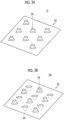
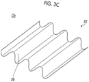
- Figs. 3A to 3C are diagrams for explaining examples of the undulating shape of the core member according to the first embodiment.
- a core member C may have a shape in which a plurality of protrusions 24 are formed on one surface of a resin sheet 22.
- the forming device 12 forms the core member C by forming the protrusions 24 on one surface of the resin sheet 22.
- a core member Ca may have a shape in which a plurality of the protrusions 24 are formed on one surface of the resin sheet 22.
- the forming device 12 forms the core member Ca by forming the protrusions 24 on both surfaces of the resin sheet 22.
- a core member Cb may have a corrugated portion 26 having a corrugated shape on a surface of the resin sheet 22.
- the forming device 12 forms the core member Cb by forming the corrugated portions 26 on both surfaces of the resin sheet 22.
- the heating device 14 heats the surface of the thermoplastic resin formed by the forming device 12.
- the heating device 14 heats, for example, an apex of an uneven portion formed on the surface of the thermoplastic resin.
- the heating device 14 may selectively heat the apex of the uneven portion formed on the surface of the thermoplastic resin.
- the heating device 14 may perform heating, for example, in a range of 150°C to 350°C, but a heating temperature is not limited thereto.
- the heating device 14 is provided, for example, inside the forming device 12.
- the heating device 14 transports the heated thermoplastic resin to the pressurizing device 18.
- the transport device 16 transports the thermoplastic resin sheet serving as the face plate of the panel structure to the pressurizing device 18.
- the thermoplastic resin transported by the transport device 16 include, but are not limited to, a polyamide resin, a polypropylene resin, an ABS resin, a polyetheretherketone, a polyetherketoneketone, and a polyphenylene sulfide.
- the thermoplastic resin is preferably thermoplastic fiber reinforced plastics containing reinforcing fibers.
- the fiber reinforced plastics are preferably, for example, glass fiber reinforced plastics and carbon fiber reinforced plastics.
- the material of the thermoplastic resin sheet transported by the transport device 16 may be the same as or different from the material of the thermoplastic resin sheet transported by the transport device 10.
- the pressurizing device 18 pressurizes and fuses the thermoplastic resin sheet serving as the core member of the panel structure transported from the forming device 12, and the thermoplastic resin sheet serving as the face plate of the panel structure transported from the transport device 16.
- the pressurizing device 18 selectively pressurizes a portion heated by the heating device 14 to fuse the thermoplastic resin sheet serving the core member of the panel structure transported from the forming device 12, and the thermoplastic resin sheet serving as the face plate of the panel structure transported from the transport device 16.
- the pressurizing device 18 manufactures the panel structure having the face plate on one surface.
- the control device 20 controls each part of the manufacturing device 1.
- the control device 20 controls the heating device 14 to control a timing of heating the thermoplastic resin.
- the control device 20 controls the pressurizing device 18 to control a timing of pressurizing the thermoplastic resin sheet transported from the forming device 12 and the thermoplastic resin sheet transported from the transport device 16.
- Fig. 2 is a diagram schematically showing a configuration of the manufacturing device according to the first embodiment.
- the manufacturing device 1 includes a belt roll 30, a tension roll 32, a pressurizing belt 34, a first roll 36, a second roll 38, a first guide roll 40, a heating section 42, a third roll 44, and a second guide roll 46.
- the belt roll 30, the tension roll 32, the pressurizing belt 34, the first roll 36, and the second roll 38 can also be referred to as a single facer forming a single-sided panel structure.
- the third roll 44 and a pressurizing device (not shown) in a subsequent stage can also be referred to as a double facer forming a double-sided panel structure.
- the belt roll 30 can be driven to rotate by a drive device (not shown).
- the tension roll 32 is rotatably supported at a predetermined interval from the belt roll 30.
- the pressurizing belt 34 is an endless belt and is hung between the belt roll 30 and the tension roll 32.
- the first roll 36 can be driven to rotate by a drive device (not shown), and an outer peripheral surface thereof is formed in a corrugated shape.
- the first roll 36 may be a gear.
- the first roll 36 is disposed below the pressurizing belt 34 in a Z direction between the belt roll 30 and the tension roll 32, and the outer peripheral surface having a corrugated shape abuts on a lower surface of the pressurizing belt 34 in a pressurized state.
- the belt roll 30, the tension roll 32, and the pressurizing belt 34 may be a type of the pressurizing device 18 shown in Fig. 1 .
- the belt roll 30, the tension roll 32, and the pressurizing belt 34 may also be referred to as a pressurizing mechanism.
- An outer peripheral surface of the second roll 38 is formed in a corrugated shape. That is, the second roll 38 may be a gear.
- the outer peripheral surface of the second roll 38 is formed in a corrugated shape so as to mesh with the first roll 36.
- the second roll 38 meshes with the outer peripheral surface of the first roll 36 below the first roll 36 in the Z direction.
- a resin sheet S1 made of a thermoplastic resin serving as the face plate of the panel structure is wound around the first guide roll 40.
- the resin sheet S1 is transported together with the pressurizing belt 34 to a gap between the pressurizing belt 34 and the first roll 36.
- the resin sheet S1 is transported in a state of being heated to a temperature equal to or higher than a predetermined temperature for fusion with a resin sheet S2.
- the predetermined temperature can be arbitrarily changed depending on the type of resin and the like.
- the belt roll 30 and the first guide roll 40 may be a type of the transport device 10 shown in Fig. 1 .
- the resin sheet S2 made of a thermoplastic resin serving as the core member of the panel structure is transported to a gap between the first roll 36 and the second roll 38 by a transport device (not shown) or the like.
- the first roll 36 and the second roll 38 form the surface into a corrugated shape at a meshing portion.
- the first roll 36 and the second roll 38 may be the forming device 12 shown in Fig. 1 .
- the first roll 36 includes the heating section 42.
- the resin sheet S2 whose surface is formed into a corrugated shape is transported to a gap between the pressurizing belt 34 and the first roll 36 by the first roll 36 while being heated by the heating section 42.
- FIGS. 4A and 4B are diagrams for explaining a method for heating the resin sheet according to the first embodiment.
- Fig. 4A shows a tooth portion 60 which is one of the corrugated shapes formed on an outer diameter of the first roll 36.
- the tooth portion 60 has a hole portion 64 in a tip portion 62.
- the number of the hole portions 64 is "three", but the number of the hole portions 64 may be larger or smaller than "three". The number, position, and size of the hole portions 64 can be arbitrarily changed according to a design.
- the heating section 42 may be, for example, a heat generating device having an electric heating wire (not shown). For example, at least a part of the tip portion 62 is heated by passing the electric heating wire through the hole portion 64 and causing the electric heating wire to generate heat. In this case, the heating section 42 heats the resin sheet S2 by the tip portion 62 heated by the electric heating wire.
- the heating section 42 may be, for example, a steam generator that ejects high-temperature steam. In this case, the heating section 42 heats at least a part of the tip portion 62 by ejecting the high-temperature steam from the hole portion 64. In this case, the heating section 42 heats the resin sheet S2 by the tip portion 62 heated by the high-temperature steam.
- the heating section 42 may be, for example, a magnetic field heating device having an exciting coil. In this case, for example, the heating section 42 generates a magnetic field outside the tooth portion 60 and heats the resin sheet S2 using an inductive resistance. The heating section 42 heats the resin sheet S2, for example, by applying a magnetic field to the tip portion 62 of the tooth portion 60 to cause the tip portion 62 to generate heat by the inductive resistance. In a case where the resin sheet S1 is not transported in a state of being heated to a predetermined temperature or higher, the heating section 42 may also heat the resin sheet S2.
- the hole portion 64 may be formed in a valley portion 66 between the tooth portion 60 and the tooth portion 60 in the first roll 36.
- the valley portion 66 may be heated by passing the electric heating wire or the high-temperature steam through the hole portions 64 formed in the valley portion 66.
- the heating section 42 preferably selectively heats the resin sheet S2. It is preferable that the heating section 42 selectively heats an apex portion of the corrugated shape of the surface of the resin sheet S2. Specifically, it is preferable that the heating section 42 selects and heats a fusing portion among the apex portions of the corrugated shape of the surface of the resin sheet S2.
- the control device 20 controls the heating section 42 to heat the resin sheet S2.
- the control device 20 controls the heating section 42 to heat the tooth portion 60 immediately after the forming by the first roll 36 is completed.
- the control device 20 controls the heating section 42 to selectively heat the apex portion of the corrugated shape of the resin sheet S2.
- the control device 20 controls the heating section 42 to select and heat the fusing portion among the apex portions of the corrugated shape of the surface of the resin sheet S2.
- the control device 20 controls the heating section 42 to heat the heating section 42 to a desired temperature immediately before the resin sheet S1 and the resin sheet S2 are fused. Since it is preferable that the resin sheets are quickly cooled after the fusion, the control device 20 controls the heating section 42 such that the heating is completed in a range of about 1/4 to 1/2 rotation immediately before the fusion in one rotation of the first roll 36.
- the resin sheet S1 and the resin sheet S2 are fused by being pressurized by the pressurizing belt 34.
- a fused portion is formed by cooling a fused location between the resin sheet S1 and the resin sheet S2.
- a single-sided panel structure P1 in which the face plate is provided on only one surface is formed.
- a cooling device that cools the resin sheet S1 and the resin sheet S2 after the resin sheet S1 and the resin sheet S2 are fused may be provided.
- the cooling device may be configured to cool at least the fused location after the resin sheet S1 and the resin sheet S2 are fused.
- the cooling device may have a water cooling structure for cooling using cooling water, or may have an air cooling structure for cooling using cooling air. By providing the cooling device, the resin sheet S1 and the resin sheet S2 can be appropriately cooled.
- a pressurizing force adjusting device capable of adjusting a pressurizing force between the first roll 36 and the pressurizing belt 34 is provided.
- the pressurizing force adjusting device has a hydraulic cylinder, and a tip portion of a drive rod thereof is connected to a supporting shaft of the tension roll 32. Therefore, the tension of the pressurizing belt 34 is adjusted by moving the tension roll 32 toward and away from the belt roll 30 by the hydraulic cylinder, and thus the pressurizing force to the resin sheet S1 and the resin sheet S2 which are transported between the first roll 36 and the pressurizing belt 34 can be adjusted.
- the single-sided panel structure P1 is transported to a gap between the tension roll 32 and the third roll 44.
- the third roll 44 has the heating section 42.
- An outer peripheral surface of the third roll 44 is formed in a corrugated shape. That is, the third roll 44 may be a gear.
- the third roll 44 is formed to mesh with the corrugated shape of the surface of the resin sheet S2.
- the single-sided panel structure P1 is transported to a pressurizing device including a pressurizing belt (not shown) by the third roll 44 while the resin sheet S2 whose surface where the resin sheet S1 is not fused is formed in a corrugated shape is heated by the heating section 42.
- the resin sheet S3 made of a thermoplastic resin serving as the face plate of the panel structure is wound around the second guide roll 46 and transported to a pressurizing device (not shown).
- the resin sheet S2 and the resin sheet S3 are fused by being pressurized by a pressurizing device (not shown). A fused portion is formed by cooling a fused location between the resin sheet S2 and the resin sheet S3. As a result, a double-sided panel structure having the face plates on both surfaces of the core member is formed.
- a cooling device (not shown) that cools the resin sheet S2 and the resin sheet S3 after the resin sheet S2 and the resin sheet S3 are fused may be provided.
- the cooling device may be configured to cool at least the fused location after the resin sheet S2 and the resin sheet S3 are fused.
- the cooling device may have a water cooling structure for cooling using cooling water, or may have an air cooling structure for cooling using cooling air. By providing the cooling device, the resin sheet S2 and the resin sheet S3 can be appropriately cooled.
- FIG. 5 is a flowchart showing an example of the panel structure manufacturing method according to the first embodiment.
- the belt roll 30 and the first guide roll 40 transport the resin sheet S1 serving as the face plate to a gap between the pressurizing belt 34 and the first roll 36 (step S10).
- a transport device or the like (not shown) transports the resin sheet S2 serving as the core member to a gap between the first roll 36 and the second roll 38 (step S12).
- the first roll 36 and the second roll 38 form the surface of the resin sheet S2 into a corrugated shape at the meshing portion (step S14).
- the heating section 42 provided on the first roll 36 selectively heats the apex portion of the corrugated shape on one surface of the resin sheet S2 (step S16).
- the pressurizing belt 34 fuses the resin sheet S1 and the resin sheet S2 by applying pressure to the resin sheet S1 and a heated location of the resin sheet S2 (step S18). As a result, the single-sided panel structure P1 is formed.
- the pressurizing belt 34 and the first roll 36 transport the single-sided panel structure P1 to a gap between the tension roll 32 and the third roll 44 (step S20).
- the heating section 42 provided on the third roll 44 selectively heats the apex portion of the corrugated shape on the other surface of the resin sheet S2 (step S22).
- a transport device or the like transports the resin sheet S3 serving as the face plate, which is wound around the second guide roll 46, to a pressurizing device (not shown) (step S24).
- a pressurizing device (not shown) fuses the resin sheet S2 and the resin sheet S3 by applying pressure to the heated location of the resin sheet S2 and the resin sheet S3 (step S26) . As a result, the double-sided panel structure is formed.
- the panel structure can be appropriately manufactured by heat fusion.
- Fig. 6 is a diagram schematically showing a configuration of the manufacturing device according to the second embodiment.
- a manufacturing device 1A is different from the manufacturing device 1 shown in Fig. 2 in that a fusion assistance device 48 is provided.
- the fusion assistance device 48 is provided in a pressurizing mechanism including the belt roll 30, the tension roll 32, and the pressurizing belt 34.
- the fusion assistance device 48 is provided, for example, in the vicinity of a location where the pressurizing belt 34 applies pressure.
- the fusion assistance device 48 has, for example, a function of assisting fusion when the pressurizing belt 34 fuses the resin sheet S1 and the resin sheet S2.
- the fusion assistance device 48 is, for example, an ultrasonic wave generator that heats a target by applying ultrasonic waves to the target.
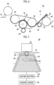
- Fig. 7 is a diagram for explaining a method for heating the resin sheet according to the second embodiment.
- Fig. 7 shows the tooth portion 60, which is one of the corrugated shapes formed on the outer diameter of the first roll 36, and the fusion assistance device 48.
- the heating section 42 causes the tip portion 62 of the tooth portion 60 to generate heat to heat a heating location 50 of the resin sheet S2.
- the fusion assistance device 48 irradiates the heating location 50 of the resin sheet S2 with ultrasonic waves to heat the heating location 50. That is, in the second embodiment, the resin sheet S1 and the resin sheet S2 are heated by using the heating section 42 and the fusion assistance device 48. As a result, in the second embodiment, a heat generation temperature generated by the heating section 42 can be lowered.
- the fusion assistance device 48 may be provided, for example, in a pressurizing device (not shown) that fuses the resin sheet S3 to the single-sided panel structure P1.
- the fusion assistance device 48 has, for example, a function of assisting fusion when the single-sided panel structure P1 and the resin sheet S2 are fused. Since a method for assisting the fusion with the fusion assistance device 48 is the same as the method for assisting the fusion between the resin sheet S1 and the resin sheet S2, the description thereof will not be repeated.
- the fusion assistance device 48 has been described as an ultrasonic wave generator that emits ultrasonic waves, but this is an example and does not limit the present disclosure.
- the fusion assistance device 48 may be, for example, a pressure applying device that applies pressure to assist application of pressure by the pressurizing belt 34.
- FIG. 8 is a flowchart showing an example of the panel structure manufacturing method according to the second embodiment.
- steps S40 to S46, steps S50 to S54, and steps S58 to S60 are the same processes as steps S10 to S26, respectively, the description thereof will not be repeated.
- step S46 the fusion assistance device 48 supplementally heats the same location as the location heated by the heating section 42 (step S48).
- a process of step S46 and a process of step S48 may be performed at the same time.
- step S54 the fusion assistance device 48 supplementally heats the same location as the location heated by the heating section 42 (step S56).
- a process of step S54 and a process of step S56 may be performed at the same time.
- the heated location is supplementally heated by the fusion assistance device 48. Accordingly, in the second embodiment, a heating temperature of the resin sheet S2 by the heating section 42 can be lowered. As a result, in the second embodiment, the resin sheet S2 can be easily cooled after being heated, so that a quality of a product can be improved.
- the panel structure manufacturing device and the panel structure manufacturing method described in the embodiments are understood as follows, for example.
- the panel structure manufacturing device includes the forming device 12 that forms the core member having a plate shape by forming the surface of the thermoplastic resin into an undulating shape, the heating device 14 that selectively heats the surface of the core member, and the pressurizing device 18 that pressurizes the heating location of the core member heated by the heating device 14 and the face plate having a plate shape to fuse the core member and the face plate.
- the panel structure manufacturing device of the first aspect selectively heats the fused location with the face plate on the surface of the core member.
- the panel structure manufacturing device of the first aspect heats the core member and the face plate by pressurizing the heating location of the core member and the face plate. Accordingly, the panel structure manufacturing device of the first aspect can appropriately manufacture the panel structure by heat fusion.
- the panel structure manufacturing device of the second aspect further includes the control device 20 that controls the heating timing of the heating device 14. Accordingly, the panel structure manufacturing device of the second aspect can appropriately control the heating timing when the core member and the face plate are fused.
- the forming device 12 forms the thermoplastic resin into a corrugated shape. Accordingly, in the panel structure manufacturing device of the third aspect, the panel structure in which the core member is formed in a corrugated shape can be manufactured by heat fusion.
- the heating device 14 heats the apex portion of the undulating shape formed on the core member. Accordingly, in the panel structure manufacturing device of the fourth aspect, the core member can be appropriately heated when the core member and the face plate are fused.
- the heating device 14 is provided in the forming device 12. Accordingly, in the panel structure manufacturing device of the fifth aspect, the core member can be heated by using the forming device 12. As a result, in the panel structure manufacturing device of the fifth aspect, the core member can be easily heated.
- the forming device 12 is a gear
- the gear has hole portions in a ridge portion and a valley portion of the tooth portion
- the heating device 14 heats the core member by using the hole portions. Accordingly, in the panel structure manufacturing device of the sixth aspect, the core member can be heated while the forming device 12 meshes with the core member formed in a corrugated shape. As a result, in the panel structure manufacturing device of the sixth aspect, the core member can be appropriately heated.
- the heating device 14 heats the gear to heat the core member by using the electric heating wire passing through the hole portion or the steam passing through the hole portion. Accordingly, in the panel structure manufacturing device of the seventh aspect, the core member can be heated more appropriately.
- the forming device 12 is a gear
- the heating device 14 generates a magnetic field outside the gear and heats the core member by using the inductive resistance. Accordingly, in the panel structure manufacturing device of the eighth aspect, the core member can be heated more appropriately.
- the panel structure manufacturing device of a ninth aspect further includes a fusion assistance device 48 that assists fusion between the core member and the face plate. Accordingly, the panel structure manufacturing device of the ninth aspect can assist the fusion between the core member and the face plate by the pressurizing device 18. Accordingly, the panel structure manufacturing device of the ninth aspect can more appropriately manufacture the panel structure by heat fusion.
- the fusion assistance device 48 is an ultrasonic heating device. Accordingly, in the panel structure manufacturing device according to the tenth aspect, the fusion assistance device 48 can supplementally heat the location heated by the heating device 14 when the core member is heated by the heating device 14 in order to fuse the core member and the face plate. As a result, the panel structure manufacturing device according to the tenth aspect can more appropriately manufacture the panel structure by heat fusion.
- the panel structure manufacturing method includes a step of forming a core member having a plate shape by forming a surface of a thermoplastic resin into an undulating shape, a step of selectively heating a surface of the core member, and a step of pressurizing a heating location of the core member and a face plate having a plate shape to fuse the core member and the face plate.
- the panel structure manufacturing method according to a twelfth aspect selectively heats the fused location with the face plate on the surface of the core member.
- the core member and the face plate are heated by pressurizing the heating location of the core member and the face plate. Accordingly, the panel structure manufacturing method according to the eleventh aspect can appropriately manufacture the panel structure by heat fusion.
- the present invention is not limited by the contents of the embodiments.
- the above-described components include those that can be easily assumed by those skilled in the art, those that are substantially the same, and those that are within a so-called equivalent range. Further, the above-described components can be combined as appropriate. Further, various omissions, replacements, and modifications of the above-described components can be made without departing from the concept of the above-described embodiments.
Landscapes
- Engineering & Computer Science (AREA)
- Mechanical Engineering (AREA)
- Architecture (AREA)
- Civil Engineering (AREA)
- Structural Engineering (AREA)
- Physics & Mathematics (AREA)
- Thermal Sciences (AREA)
- Lining Or Joining Of Plastics Or The Like (AREA)
- Panels For Use In Building Construction (AREA)
Abstract
Description
- The present disclosure relates to a panel structure manufacturing device and a panel structure manufacturing method.
- A technique capable of manufacturing a composite sheet by fusing a plurality of sheets using an ultrasonic fusion machine is known (for example, PTL 1).
- [PTL 1]
Japanese Unexamined Patent Application Publication No. 2019-188802 - It has been studied to manufacture a sandwich panel containing a thermoplastic resin by fusion, which is used for automobiles, trains, other mobility products, building materials, and the like, using a corrugator that manufactures a corrugated cardboard in the related art. In order to fuse two thermoplastic resins, it is necessary to apply appropriate heat and pressure to the thermoplastic resins. However, depending on a type of a resin material of the thermoplastic resin and a temperature rise state, the pressure may be insufficient and a panel structure may not be manufactured appropriately.
- An object of the present disclosure is to provide a panel structure manufacturing device and a panel structure manufacturing method capable of appropriately manufacturing a panel structure by fusion.
- A panel structure manufacturing device according to one aspect of the present disclosure includes a forming device that forms a core member having a plate shape by forming a surface of a thermoplastic resin into an undulating shape, a heating device that selectively heats a surface of the core member, and a pressurizing device that pressurizes a heating location of the core member heated by the heating device and a face plate having a plate shape to fuse the core member and the face plate.
- A panel structure manufacturing method according to another aspect of the present disclosure includes a step of forming a core member having a plate shape by forming a surface of a thermoplastic resin into an undulating shape, a step of selectively heating a surface of the core member, and a step of pressurizing a heating location of the core member heated by the heating device and a face plate having a plate shape to fuse the core member and the face plate.
- According to the present disclosure, the panel structure can be appropriately manufactured by heat fusion. Brief Description of Drawings
-
-
Fig. 1 is a block diagram showing a configuration example of a manufacturing device for manufacturing a panel structure according to a first embodiment by heat fusion. -
Fig. 2 is a diagram schematically showing a configuration of the manufacturing device according to the first embodiment. -
Fig. 3A is a diagram for explaining an example of the undulating shape of the core member according to the first embodiment. -
Fig. 3B is a diagram for explaining an example of the undulating shape of the core member according to the first embodiment. -
Fig. 3C is a diagram for explaining an example of the undulating shape of the core member according to the first embodiment. -
Fig. 4A is a diagram for explaining a method for heating a resin sheet according to the first embodiment. -
Fig. 4B is a diagram for explaining a method for heating the resin sheet according to the first embodiment. -
Fig. 5 is a flowchart showing an example of a panel structure manufacturing method according to the first embodiment. -
Fig. 6 is a diagram schematically showing a configuration of a manufacturing device according to a second embodiment. -
Fig. 7 is a diagram for explaining a method for heating a resin sheet according to the second embodiment. -
Fig. 8 is a flowchart showing an example of a panel structure manufacturing method according to the second embodiment. - Hereinafter, embodiments according to the present invention will be described in detail with reference to the accompanying drawings. The present invention is not limited by the embodiments. In a case where there are a plurality of the embodiments, the present invention also includes those configured by combining the embodiments. In addition, in the following embodiments, the same parts are denoted by the same reference signs, and the duplicate descriptions will not be repeated.
- A manufacturing device for manufacturing a panel structure according to a first embodiment by heat fusion will be described with reference to
Fig. 1. Fig. 1 is a block diagram showing a configuration example of a manufacturing device for manufacturing a panel structure according to the first embodiment by heat fusion. - As shown in
Fig. 1 , a panelstructure manufacturing device 1 includes atransport device 10, a formingdevice 12, aheating device 14, atransport device 16, a pressurizingdevice 18, and acontrol device 20. Themanufacturing device 1 is a device capable of appropriately manufacturing a panel structure by appropriately fusing a core member and a face plate. - The
transport device 10 transports a thermoplastic resin sheet serving as the core member of the panel structure to the formingdevice 12. Examples of a thermoplastic resin transported by thetransport device 10 include, but are not limited to, a polyamide resin, a polypropylene resin, an ABS resin, a polyetheretherketone, a polyetherketoneketone, and a polyphenylene sulfide. The thermoplastic resin is preferably thermoplastic fiber reinforced plastics (FRP) containing reinforcing fibers. The fiber reinforced plastics are preferably, for example, glass fiber reinforced plastics (GFRP) and carbon fiber reinforced plastics (CFRP). - The forming
device 12 forms a surface of the thermoplastic resin transported from the transport device into an undulating shape to produce a core member. The undulating shape may include various shapes such as a single-sided protrusion shape in which protrusions are formed on only one surface, a double-sided protrusion shape in which protrusions are formed on both surfaces, and a corrugated shape in which both surfaces are formed in a corrugated shape. The formingdevice 12 may form the core member by forming the surface of the thermoplastic resin into other shapes. - The undulating shape of the core member formed by the forming
device 12 will be described with reference toFigs. 3A, 3B , and3C .Figs. 3A to 3C are diagrams for explaining examples of the undulating shape of the core member according to the first embodiment. - As shown in
Fig. 3A , a core member C may have a shape in which a plurality ofprotrusions 24 are formed on one surface of aresin sheet 22. In this case, the formingdevice 12 forms the core member C by forming theprotrusions 24 on one surface of theresin sheet 22. - As shown in
Fig. 3B , a core member Ca may have a shape in which a plurality of theprotrusions 24 are formed on one surface of theresin sheet 22. In this case, the formingdevice 12 forms the core member Ca by forming theprotrusions 24 on both surfaces of theresin sheet 22. - As shown in
Fig. 3C , a core member Cb may have acorrugated portion 26 having a corrugated shape on a surface of theresin sheet 22. In this case, the formingdevice 12 forms the core member Cb by forming thecorrugated portions 26 on both surfaces of theresin sheet 22. - The
heating device 14 heats the surface of the thermoplastic resin formed by the formingdevice 12. Theheating device 14 heats, for example, an apex of an uneven portion formed on the surface of the thermoplastic resin. For example, theheating device 14 may selectively heat the apex of the uneven portion formed on the surface of the thermoplastic resin. Theheating device 14 may perform heating, for example, in a range of 150°C to 350°C, but a heating temperature is not limited thereto. Theheating device 14 is provided, for example, inside the formingdevice 12. Theheating device 14 transports the heated thermoplastic resin to the pressurizingdevice 18. - The
transport device 16 transports the thermoplastic resin sheet serving as the face plate of the panel structure to the pressurizingdevice 18. Examples of the thermoplastic resin transported by thetransport device 16 include, but are not limited to, a polyamide resin, a polypropylene resin, an ABS resin, a polyetheretherketone, a polyetherketoneketone, and a polyphenylene sulfide. The thermoplastic resin is preferably thermoplastic fiber reinforced plastics containing reinforcing fibers. The fiber reinforced plastics are preferably, for example, glass fiber reinforced plastics and carbon fiber reinforced plastics. The material of the thermoplastic resin sheet transported by thetransport device 16 may be the same as or different from the material of the thermoplastic resin sheet transported by thetransport device 10. - The pressurizing
device 18 pressurizes and fuses the thermoplastic resin sheet serving as the core member of the panel structure transported from the formingdevice 12, and the thermoplastic resin sheet serving as the face plate of the panel structure transported from thetransport device 16. For example, the pressurizingdevice 18 selectively pressurizes a portion heated by theheating device 14 to fuse the thermoplastic resin sheet serving the core member of the panel structure transported from the formingdevice 12, and the thermoplastic resin sheet serving as the face plate of the panel structure transported from thetransport device 16. The pressurizingdevice 18 manufactures the panel structure having the face plate on one surface. - The
control device 20 controls each part of themanufacturing device 1. For example, thecontrol device 20 controls theheating device 14 to control a timing of heating the thermoplastic resin. For example, thecontrol device 20 controls the pressurizingdevice 18 to control a timing of pressurizing the thermoplastic resin sheet transported from the formingdevice 12 and the thermoplastic resin sheet transported from thetransport device 16. - The details of the manufacturing device according to the first embodiment will be described with reference to
Fig. 2. Fig. 2 is a diagram schematically showing a configuration of the manufacturing device according to the first embodiment. - As shown in
Fig. 2 , themanufacturing device 1 includes abelt roll 30, atension roll 32, a pressurizingbelt 34, afirst roll 36, asecond roll 38, afirst guide roll 40, aheating section 42, athird roll 44, and asecond guide roll 46. - The
belt roll 30, thetension roll 32, the pressurizingbelt 34, thefirst roll 36, and thesecond roll 38 can also be referred to as a single facer forming a single-sided panel structure. Thethird roll 44 and a pressurizing device (not shown) in a subsequent stage can also be referred to as a double facer forming a double-sided panel structure. - The
belt roll 30 can be driven to rotate by a drive device (not shown). Thetension roll 32 is rotatably supported at a predetermined interval from thebelt roll 30. The pressurizingbelt 34 is an endless belt and is hung between thebelt roll 30 and thetension roll 32. - The
first roll 36 can be driven to rotate by a drive device (not shown), and an outer peripheral surface thereof is formed in a corrugated shape. In other words, thefirst roll 36 may be a gear. Thefirst roll 36 is disposed below the pressurizingbelt 34 in a Z direction between thebelt roll 30 and thetension roll 32, and the outer peripheral surface having a corrugated shape abuts on a lower surface of the pressurizingbelt 34 in a pressurized state. Thebelt roll 30, thetension roll 32, and the pressurizingbelt 34 may be a type of the pressurizingdevice 18 shown inFig. 1 . Thebelt roll 30, thetension roll 32, and the pressurizingbelt 34 may also be referred to as a pressurizing mechanism. - An outer peripheral surface of the
second roll 38 is formed in a corrugated shape. That is, thesecond roll 38 may be a gear. The outer peripheral surface of thesecond roll 38 is formed in a corrugated shape so as to mesh with thefirst roll 36. Thesecond roll 38 meshes with the outer peripheral surface of thefirst roll 36 below thefirst roll 36 in the Z direction. - A resin sheet S1 made of a thermoplastic resin serving as the face plate of the panel structure is wound around the
first guide roll 40. As thebelt roll 30 rotates, the resin sheet S1 is transported together with the pressurizingbelt 34 to a gap between the pressurizingbelt 34 and thefirst roll 36. Here, it is preferable that the resin sheet S1 is transported in a state of being heated to a temperature equal to or higher than a predetermined temperature for fusion with a resin sheet S2. The predetermined temperature can be arbitrarily changed depending on the type of resin and the like. Thebelt roll 30 and thefirst guide roll 40 may be a type of thetransport device 10 shown inFig. 1 . - The resin sheet S2 made of a thermoplastic resin serving as the core member of the panel structure is transported to a gap between the
first roll 36 and thesecond roll 38 by a transport device (not shown) or the like. Thefirst roll 36 and thesecond roll 38 form the surface into a corrugated shape at a meshing portion. Thefirst roll 36 and thesecond roll 38 may be the formingdevice 12 shown inFig. 1 . - The
first roll 36 includes theheating section 42. The resin sheet S2 whose surface is formed into a corrugated shape is transported to a gap between the pressurizingbelt 34 and thefirst roll 36 by thefirst roll 36 while being heated by theheating section 42. - A method for heating the resin sheet according to the first embodiment will be described with reference to
Figs. 4A and 4B. Figs. 4A and 4B are diagrams for explaining a method for heating the resin sheet according to the first embodiment. -
Fig. 4A shows atooth portion 60 which is one of the corrugated shapes formed on an outer diameter of thefirst roll 36. As shown inFig. 4A , thetooth portion 60 has ahole portion 64 in atip portion 62. InFig. 4A , the number of thehole portions 64 is "three", but the number of thehole portions 64 may be larger or smaller than "three". The number, position, and size of thehole portions 64 can be arbitrarily changed according to a design. - The
heating section 42 may be, for example, a heat generating device having an electric heating wire (not shown). For example, at least a part of thetip portion 62 is heated by passing the electric heating wire through thehole portion 64 and causing the electric heating wire to generate heat. In this case, theheating section 42 heats the resin sheet S2 by thetip portion 62 heated by the electric heating wire. - The
heating section 42 may be, for example, a steam generator that ejects high-temperature steam. In this case, theheating section 42 heats at least a part of thetip portion 62 by ejecting the high-temperature steam from thehole portion 64. In this case, theheating section 42 heats the resin sheet S2 by thetip portion 62 heated by the high-temperature steam. - The
heating section 42 may be, for example, a magnetic field heating device having an exciting coil. In this case, for example, theheating section 42 generates a magnetic field outside thetooth portion 60 and heats the resin sheet S2 using an inductive resistance. Theheating section 42 heats the resin sheet S2, for example, by applying a magnetic field to thetip portion 62 of thetooth portion 60 to cause thetip portion 62 to generate heat by the inductive resistance. In a case where the resin sheet S1 is not transported in a state of being heated to a predetermined temperature or higher, theheating section 42 may also heat the resin sheet S2. - As shown in
Fig. 4B , thehole portion 64 may be formed in avalley portion 66 between thetooth portion 60 and thetooth portion 60 in thefirst roll 36. Specifically, in a case where the resin sheet S2 and a resin sheet S3 are fused as described later, thevalley portion 66 may be heated by passing the electric heating wire or the high-temperature steam through thehole portions 64 formed in thevalley portion 66. - The
heating section 42 preferably selectively heats the resin sheet S2. It is preferable that theheating section 42 selectively heats an apex portion of the corrugated shape of the surface of the resin sheet S2. Specifically, it is preferable that theheating section 42 selects and heats a fusing portion among the apex portions of the corrugated shape of the surface of the resin sheet S2. - The
control device 20 controls theheating section 42 to heat the resin sheet S2. For example, thecontrol device 20 controls theheating section 42 to heat thetooth portion 60 immediately after the forming by thefirst roll 36 is completed. Thecontrol device 20 controls theheating section 42 to selectively heat the apex portion of the corrugated shape of the resin sheet S2. Specifically, thecontrol device 20 controls theheating section 42 to select and heat the fusing portion among the apex portions of the corrugated shape of the surface of the resin sheet S2. Thecontrol device 20 controls theheating section 42 to heat theheating section 42 to a desired temperature immediately before the resin sheet S1 and the resin sheet S2 are fused. Since it is preferable that the resin sheets are quickly cooled after the fusion, thecontrol device 20 controls theheating section 42 such that the heating is completed in a range of about 1/4 to 1/2 rotation immediately before the fusion in one rotation of thefirst roll 36. - When the heating of the resin sheet S2 is completed, the resin sheet S1 and the resin sheet S2 are fused by being pressurized by the pressurizing
belt 34. A fused portion is formed by cooling a fused location between the resin sheet S1 and the resin sheet S2. As a result, a single-sided panel structure P1 in which the face plate is provided on only one surface is formed. - Further, a cooling device (not shown) that cools the resin sheet S1 and the resin sheet S2 after the resin sheet S1 and the resin sheet S2 are fused may be provided. In this case, the cooling device may be configured to cool at least the fused location after the resin sheet S1 and the resin sheet S2 are fused. The cooling device may have a water cooling structure for cooling using cooling water, or may have an air cooling structure for cooling using cooling air. By providing the cooling device, the resin sheet S1 and the resin sheet S2 can be appropriately cooled.
- Further, although not shown, a pressurizing force adjusting device capable of adjusting a pressurizing force between the
first roll 36 and the pressurizingbelt 34 is provided. For example, the pressurizing force adjusting device has a hydraulic cylinder, and a tip portion of a drive rod thereof is connected to a supporting shaft of thetension roll 32. Therefore, the tension of the pressurizingbelt 34 is adjusted by moving thetension roll 32 toward and away from thebelt roll 30 by the hydraulic cylinder, and thus the pressurizing force to the resin sheet S1 and the resin sheet S2 which are transported between thefirst roll 36 and the pressurizingbelt 34 can be adjusted. - Returning to
Fig. 2 , the single-sided panel structure P1 is transported to a gap between thetension roll 32 and thethird roll 44. - The
third roll 44 has theheating section 42. An outer peripheral surface of thethird roll 44 is formed in a corrugated shape. That is, thethird roll 44 may be a gear. Thethird roll 44 is formed to mesh with the corrugated shape of the surface of the resin sheet S2. The single-sided panel structure P1 is transported to a pressurizing device including a pressurizing belt (not shown) by thethird roll 44 while the resin sheet S2 whose surface where the resin sheet S1 is not fused is formed in a corrugated shape is heated by theheating section 42. - The resin sheet S3 made of a thermoplastic resin serving as the face plate of the panel structure is wound around the
second guide roll 46 and transported to a pressurizing device (not shown). - In the single-sided panel structure P1, when the heating of the resin sheet S2 whose surface where the resin sheet S1 is not fused is formed into a corrugated shape is completed, the resin sheet S2 and the resin sheet S3 are fused by being pressurized by a pressurizing device (not shown). A fused portion is formed by cooling a fused location between the resin sheet S2 and the resin sheet S3. As a result, a double-sided panel structure having the face plates on both surfaces of the core member is formed.
- Further, a cooling device (not shown) that cools the resin sheet S2 and the resin sheet S3 after the resin sheet S2 and the resin sheet S3 are fused may be provided. In this case, the cooling device may be configured to cool at least the fused location after the resin sheet S2 and the resin sheet S3 are fused. The cooling device may have a water cooling structure for cooling using cooling water, or may have an air cooling structure for cooling using cooling air. By providing the cooling device, the resin sheet S2 and the resin sheet S3 can be appropriately cooled.
- A panel structure manufacturing method according to the first embodiment will be described with reference to
Fig. 5. Fig. 5 is a flowchart showing an example of the panel structure manufacturing method according to the first embodiment. - First, the
belt roll 30 and thefirst guide roll 40 transport the resin sheet S1 serving as the face plate to a gap between the pressurizingbelt 34 and the first roll 36 (step S10). A transport device or the like (not shown) transports the resin sheet S2 serving as the core member to a gap between thefirst roll 36 and the second roll 38 (step S12). - The
first roll 36 and thesecond roll 38 form the surface of the resin sheet S2 into a corrugated shape at the meshing portion (step S14). Theheating section 42 provided on thefirst roll 36 selectively heats the apex portion of the corrugated shape on one surface of the resin sheet S2 (step S16). - The pressurizing
belt 34 fuses the resin sheet S1 and the resin sheet S2 by applying pressure to the resin sheet S1 and a heated location of the resin sheet S2 (step S18). As a result, the single-sided panel structure P1 is formed. - The pressurizing
belt 34 and thefirst roll 36 transport the single-sided panel structure P1 to a gap between thetension roll 32 and the third roll 44 (step S20). Theheating section 42 provided on thethird roll 44 selectively heats the apex portion of the corrugated shape on the other surface of the resin sheet S2 (step S22). A transport device or the like (not shown) transports the resin sheet S3 serving as the face plate, which is wound around thesecond guide roll 46, to a pressurizing device (not shown) (step S24). - A pressurizing device (not shown) fuses the resin sheet S2 and the resin sheet S3 by applying pressure to the heated location of the resin sheet S2 and the resin sheet S3 (step S26) . As a result, the double-sided panel structure is formed.
- As described above, in the first embodiment, a part of the corrugated shape of the resin sheet S2 serving as the core member is selectively heated, and pressure is applied to the resin sheet S1 or the resin sheet S3 serving as the face plate and the resin sheet S2 to fuse them together. Accordingly, in the first embodiment, the panel structure can be appropriately manufactured by heat fusion.
- The details of a manufacturing device according to the second embodiment will be described with reference to
Fig. 6. Fig. 6 is a diagram schematically showing a configuration of the manufacturing device according to the second embodiment. - As shown in
Fig. 6 , amanufacturing device 1A is different from themanufacturing device 1 shown inFig. 2 in that afusion assistance device 48 is provided. - The
fusion assistance device 48 is provided in a pressurizing mechanism including thebelt roll 30, thetension roll 32, and the pressurizingbelt 34. Thefusion assistance device 48 is provided, for example, in the vicinity of a location where the pressurizingbelt 34 applies pressure. Thefusion assistance device 48 has, for example, a function of assisting fusion when the pressurizingbelt 34 fuses the resin sheet S1 and the resin sheet S2. Thefusion assistance device 48 is, for example, an ultrasonic wave generator that heats a target by applying ultrasonic waves to the target. - A method for heating the resin sheet according to the second embodiment will be described with reference to
Fig. 7. Fig. 7 is a diagram for explaining a method for heating the resin sheet according to the second embodiment. -
Fig. 7 shows thetooth portion 60, which is one of the corrugated shapes formed on the outer diameter of thefirst roll 36, and thefusion assistance device 48. - In the second embodiment, the
heating section 42 causes thetip portion 62 of thetooth portion 60 to generate heat to heat aheating location 50 of the resin sheet S2. Thefusion assistance device 48 irradiates theheating location 50 of the resin sheet S2 with ultrasonic waves to heat theheating location 50. That is, in the second embodiment, the resin sheet S1 and the resin sheet S2 are heated by using theheating section 42 and thefusion assistance device 48. As a result, in the second embodiment, a heat generation temperature generated by theheating section 42 can be lowered. - Returning to
Fig. 6 , thefusion assistance device 48 may be provided, for example, in a pressurizing device (not shown) that fuses the resin sheet S3 to the single-sided panel structure P1. In this case, thefusion assistance device 48 has, for example, a function of assisting fusion when the single-sided panel structure P1 and the resin sheet S2 are fused. Since a method for assisting the fusion with thefusion assistance device 48 is the same as the method for assisting the fusion between the resin sheet S1 and the resin sheet S2, the description thereof will not be repeated. - In the second embodiment, the
fusion assistance device 48 has been described as an ultrasonic wave generator that emits ultrasonic waves, but this is an example and does not limit the present disclosure. Thefusion assistance device 48 may be, for example, a pressure applying device that applies pressure to assist application of pressure by the pressurizingbelt 34. - A panel structure manufacturing method according to the second embodiment will be described with reference to
Fig. 8. Fig. 8 is a flowchart showing an example of the panel structure manufacturing method according to the second embodiment. - Since steps S40 to S46, steps S50 to S54, and steps S58 to S60 are the same processes as steps S10 to S26, respectively, the description thereof will not be repeated.
- After step S46, the
fusion assistance device 48 supplementally heats the same location as the location heated by the heating section 42 (step S48). A process of step S46 and a process of step S48 may be performed at the same time. - After step S54, the
fusion assistance device 48 supplementally heats the same location as the location heated by the heating section 42 (step S56). A process of step S54 and a process of step S56 may be performed at the same time. - As described above, in the second embodiment, when a part of the corrugated shape of the resin sheet S2 serving as the core member is selectively heated, the heated location is supplementally heated by the
fusion assistance device 48. Accordingly, in the second embodiment, a heating temperature of the resin sheet S2 by theheating section 42 can be lowered. As a result, in the second embodiment, the resin sheet S2 can be easily cooled after being heated, so that a quality of a product can be improved. - The panel structure manufacturing device and the panel structure manufacturing method described in the embodiments are understood as follows, for example.
- The panel structure manufacturing device according to a first aspect includes the forming
device 12 that forms the core member having a plate shape by forming the surface of the thermoplastic resin into an undulating shape, theheating device 14 that selectively heats the surface of the core member, and the pressurizingdevice 18 that pressurizes the heating location of the core member heated by theheating device 14 and the face plate having a plate shape to fuse the core member and the face plate. - The panel structure manufacturing device of the first aspect selectively heats the fused location with the face plate on the surface of the core member. The panel structure manufacturing device of the first aspect heats the core member and the face plate by pressurizing the heating location of the core member and the face plate. Accordingly, the panel structure manufacturing device of the first aspect can appropriately manufacture the panel structure by heat fusion.
- The panel structure manufacturing device of the second aspect further includes the
control device 20 that controls the heating timing of theheating device 14. Accordingly, the panel structure manufacturing device of the second aspect can appropriately control the heating timing when the core member and the face plate are fused. - In the panel structure manufacturing device of a third aspect, the forming
device 12 forms the thermoplastic resin into a corrugated shape. Accordingly, in the panel structure manufacturing device of the third aspect, the panel structure in which the core member is formed in a corrugated shape can be manufactured by heat fusion. - In the panel structure manufacturing device of a fourth aspect, the
heating device 14 heats the apex portion of the undulating shape formed on the core member. Accordingly, in the panel structure manufacturing device of the fourth aspect, the core member can be appropriately heated when the core member and the face plate are fused. - In the panel structure manufacturing device of a fifth aspect, the
heating device 14 is provided in the formingdevice 12. Accordingly, in the panel structure manufacturing device of the fifth aspect, the core member can be heated by using the formingdevice 12. As a result, in the panel structure manufacturing device of the fifth aspect, the core member can be easily heated. - In the panel structure manufacturing device of a sixth aspect, the forming
device 12 is a gear, the gear has hole portions in a ridge portion and a valley portion of the tooth portion, and theheating device 14 heats the core member by using the hole portions. Accordingly, in the panel structure manufacturing device of the sixth aspect, the core member can be heated while the formingdevice 12 meshes with the core member formed in a corrugated shape. As a result, in the panel structure manufacturing device of the sixth aspect, the core member can be appropriately heated. - In the panel structure manufacturing device of a seventh aspect, the
heating device 14 heats the gear to heat the core member by using the electric heating wire passing through the hole portion or the steam passing through the hole portion. Accordingly, in the panel structure manufacturing device of the seventh aspect, the core member can be heated more appropriately. - In the panel structure manufacturing device of an eighth aspect, the forming
device 12 is a gear, and theheating device 14 generates a magnetic field outside the gear and heats the core member by using the inductive resistance. Accordingly, in the panel structure manufacturing device of the eighth aspect, the core member can be heated more appropriately. - The panel structure manufacturing device of a ninth aspect further includes a
fusion assistance device 48 that assists fusion between the core member and the face plate. Accordingly, the panel structure manufacturing device of the ninth aspect can assist the fusion between the core member and the face plate by the pressurizingdevice 18. Accordingly, the panel structure manufacturing device of the ninth aspect can more appropriately manufacture the panel structure by heat fusion. - In the panel structure manufacturing device of a tenth aspect, the
fusion assistance device 48 is an ultrasonic heating device. Accordingly, in the panel structure manufacturing device according to the tenth aspect, thefusion assistance device 48 can supplementally heat the location heated by theheating device 14 when the core member is heated by theheating device 14 in order to fuse the core member and the face plate. As a result, the panel structure manufacturing device according to the tenth aspect can more appropriately manufacture the panel structure by heat fusion. - The panel structure manufacturing method according to an eleventh aspect includes a step of forming a core member having a plate shape by forming a surface of a thermoplastic resin into an undulating shape, a step of selectively heating a surface of the core member, and a step of pressurizing a heating location of the core member and a face plate having a plate shape to fuse the core member and the face plate.
- The panel structure manufacturing method according to a twelfth aspect selectively heats the fused location with the face plate on the surface of the core member. In the panel structure manufacturing method according to the eleventh aspect, the core member and the face plate are heated by pressurizing the heating location of the core member and the face plate. Accordingly, the panel structure manufacturing method according to the eleventh aspect can appropriately manufacture the panel structure by heat fusion.
- The embodiments of the present disclosure have been described above; however, the present invention is not limited by the contents of the embodiments. In addition, the above-described components include those that can be easily assumed by those skilled in the art, those that are substantially the same, and those that are within a so-called equivalent range. Further, the above-described components can be combined as appropriate. Further, various omissions, replacements, and modifications of the above-described components can be made without departing from the concept of the above-described embodiments.
-
- 10, 16:
- transport device
- 12:
- forming device
- 14:
- heating device
- 18:
- pressurizing device
- 20:
- control device
- 30:
- belt roll
- 32:
- tension roll
- 34:
- pressurizing belt
- 36:
- first roll
- 38:
- second roll
- 40:
- first guide roll
- 42:
- heating section
- 44:
- third roll
- 46:
- second guide roll
- 48:
- fusion assistance device
Claims (11)
- A panel structure manufacturing device comprising:a forming device that forms a core member having a plate shape by forming a surface of a thermoplastic resin into an undulating shape;a heating device that selectively heats a surface of the core member; anda pressurizing device that pressurizes a heating location of the core member heated by the heating device and a face plate having a plate shape to fuse the core member and the face plate.
- The panel structure manufacturing device according to Claim 1, further comprising a control device that controls a heating timing of the heating device.
- The panel structure manufacturing device according to Claim 1 or 2, wherein the forming device forms the thermoplastic resin into a corrugated shape.
- The panel structure manufacturing device according to any one of Claims 1 to 3, wherein the heating device heats an apex portion of the undulating shape formed on the core member.
- The panel structure manufacturing device according to any one of Claims 1 to 4, wherein the heating device is provided in the forming device.
- The panel structure manufacturing device according to any one of Claims 1 to 5, wherein the forming device is a gear,the gear has hole portions in a ridge portion and a valley portion of a tooth portion, andthe heating device heats the core member by using the hole portions.
- The panel structure manufacturing device according to Claim 6, wherein the heating device heats the gear to heat the core member by using an electric heating wire passing through the hole portion or steam passing through the hole portion.
- The panel structure manufacturing device according to any one of Claims 1 to 5, wherein the forming device is a gear, and
the heating device generates a magnetic field outside the gear and heats the core member by using an inductive resistance. - The panel structure manufacturing device according to any one of Claims 1 to 8, further comprising a fusion assistance device that assists fusion between the core member and the face plate.
- The panel structure manufacturing device according to Claim 9, wherein the fusion assistance device is an ultrasonic heating device.
- A panel structure manufacturing method comprising:a step of forming a core member having a plate shape by forming a surface of a thermoplastic resin into an undulating shape;a step of selectively heating a surface of the core member; anda step of pressurizing a heating location of the core member and a face plate having a plate shape to fuse the core member and the face plate.
Applications Claiming Priority (2)
| Application Number | Priority Date | Filing Date | Title |
|---|---|---|---|
| JP2021069991A JP7664072B2 (en) | 2021-04-16 | 2021-04-16 | Apparatus and method for manufacturing panel structure |
| PCT/JP2022/005715 WO2022219910A1 (en) | 2021-04-16 | 2022-02-14 | Panel structure manufacturing device and panel structure manufacturing method |
Publications (2)
| Publication Number | Publication Date |
|---|---|
| EP4306294A1 true EP4306294A1 (en) | 2024-01-17 |
| EP4306294A4 EP4306294A4 (en) | 2024-11-06 |
Family
ID=83639580
Family Applications (1)
| Application Number | Title | Priority Date | Filing Date |
|---|---|---|---|
| EP22787838.6A Pending EP4306294A4 (en) | 2021-04-16 | 2022-02-14 | Panel structure manufacturing device and panel structure manufacturing method |
Country Status (4)
| Country | Link |
|---|---|
| US (1) | US20240191502A1 (en) |
| EP (1) | EP4306294A4 (en) |
| JP (1) | JP7664072B2 (en) |
| WO (1) | WO2022219910A1 (en) |
Family Cites Families (11)
| Publication number | Priority date | Publication date | Assignee | Title |
|---|---|---|---|---|
| JPS5118468B1 (en) * | 1969-08-05 | 1976-06-10 | ||
| US4132581A (en) * | 1976-12-27 | 1979-01-02 | Standard Oil Company (Indiana) | Method for the fabrication of plasticboard |
| US7041187B2 (en) * | 2003-11-05 | 2006-05-09 | Plc Engineering Corp. | Corrugated sandwich panel and method for manufacturing the same |
| JP2006185696A (en) * | 2004-12-27 | 2006-07-13 | Hirano Giken Kogyo Kk | Heating roll |
| JP4448061B2 (en) * | 2005-06-06 | 2010-04-07 | シーケーディ株式会社 | SEALING DEVICE AND PTP SHEET MANUFACTURING DEVICE |
| JP4822266B2 (en) * | 2006-03-29 | 2011-11-24 | 株式会社ササクラ | Mounting structure of electronic components on a rotary roll |
| JP5946305B2 (en) * | 2012-03-28 | 2016-07-06 | 宇部エクシモ株式会社 | Hollow structure plate manufacturing method and manufacturing apparatus |
| JP7084130B2 (en) * | 2016-12-19 | 2022-06-14 | 花王株式会社 | Manufacturing method and manufacturing equipment for composite sheets |
| US10323413B1 (en) * | 2017-04-12 | 2019-06-18 | John Biesiadecki | Building panel structure and method of manufacturing thereof |
| JP6592632B1 (en) | 2018-04-20 | 2019-10-16 | 花王株式会社 | Composite sheet manufacturing apparatus and manufacturing method |
| EP3643471A1 (en) * | 2018-10-26 | 2020-04-29 | Morita Giken Inc. | Plastic laminated structure and method for producing the same |
-
2021
- 2021-04-16 JP JP2021069991A patent/JP7664072B2/en active Active
-
2022
- 2022-02-14 US US18/286,271 patent/US20240191502A1/en active Pending
- 2022-02-14 WO PCT/JP2022/005715 patent/WO2022219910A1/en not_active Ceased
- 2022-02-14 EP EP22787838.6A patent/EP4306294A4/en active Pending
Also Published As
| Publication number | Publication date |
|---|---|
| WO2022219910A1 (en) | 2022-10-20 |
| US20240191502A1 (en) | 2024-06-13 |
| JP2022164476A (en) | 2022-10-27 |
| JP7664072B2 (en) | 2025-04-17 |
| EP4306294A4 (en) | 2024-11-06 |
Similar Documents
| Publication | Publication Date | Title |
|---|---|---|
| EP2083502B1 (en) | Laminated core, method and apparatus for manufacturing laminated core, and stator | |
| US6702918B2 (en) | Intermittent material feed type variable-lamination rapid prototyping process and apparatus using linear thermal cutting system | |
| US4490199A (en) | Method and apparatus for splicing polymeric webs | |
| WO2011046137A1 (en) | Method and device for manufacturing beam member | |
| WO2003026821A1 (en) | Apparatus and method for induction lamination of electrically conductive fiber reinforced composite materials | |
| JP2016528074A (en) | Method and apparatus for manufacturing composite materials | |
| DE102010041432A1 (en) | Ultrasonic resonator | |
| US9333730B2 (en) | Manufacturing method for composite structure | |
| JP6411677B1 (en) | Manufacturing method of composite material part and composite material part manufacturing apparatus | |
| CN111565920A (en) | Thermoplastic composite master and tape and method | |
| WO2017042920A1 (en) | Composite material production method, composite material production device, preform for composite material, and composite material | |
| US20240191502A1 (en) | Panel structure manufacturing device and panel structure manufacturing method | |
| US20190134920A1 (en) | Fiber-reinforced thermoplastic resin member welding method and welding device | |
| JP3655387B2 (en) | Laminated sheet manufacturing method | |
| EP4140876A2 (en) | Control surface and method of making the same | |
| JPH09254311A (en) | Method for manufacture of laminate and apparatus therefor | |
| JP2015185566A (en) | Superconducting coil and method and apparatus for manufacturing the same | |
| EP4151400A1 (en) | Roll-up band and use of the same for manufacturing mesh bags | |
| CN108430773A (en) | Ultrasonic sealing device | |
| US6896761B1 (en) | Method of manufacturing a composite material | |
| JP2015027781A (en) | Sheet material manufacturing apparatus and method | |
| CN105102206B (en) | Method for packaging laminate processing and apparatus for carrying out the method | |
| DE202011108504U1 (en) | Apparatus for ultrasonic welding | |
| JP7598817B2 (en) | Panel manufacturing apparatus, panel manufacturing method, and panel | |
| US20260027788A1 (en) | Systems and methods of in-situ consolidation of afp thermoplastic composites |
Legal Events
| Date | Code | Title | Description |
|---|---|---|---|
| STAA | Information on the status of an ep patent application or granted ep patent |
Free format text: STATUS: THE INTERNATIONAL PUBLICATION HAS BEEN MADE |
|
| PUAI | Public reference made under article 153(3) epc to a published international application that has entered the european phase |
Free format text: ORIGINAL CODE: 0009012 |
|
| STAA | Information on the status of an ep patent application or granted ep patent |
Free format text: STATUS: REQUEST FOR EXAMINATION WAS MADE |
|
| 17P | Request for examination filed |
Effective date: 20231011 |
|
| AK | Designated contracting states |
Kind code of ref document: A1 Designated state(s): AL AT BE BG CH CY CZ DE DK EE ES FI FR GB GR HR HU IE IS IT LI LT LU LV MC MK MT NL NO PL PT RO RS SE SI SK SM TR |
|
| DAV | Request for validation of the european patent (deleted) | ||
| DAX | Request for extension of the european patent (deleted) | ||
| A4 | Supplementary search report drawn up and despatched |
Effective date: 20241007 |
|
| RIC1 | Information provided on ipc code assigned before grant |
Ipc: B29L 24/00 20060101ALN20240930BHEP Ipc: B29C 53/24 20060101ALI20240930BHEP Ipc: B29C 65/18 20060101ALI20240930BHEP Ipc: B29C 65/30 20060101ALI20240930BHEP Ipc: B29C 65/72 20060101ALI20240930BHEP Ipc: E04C 2/32 20060101ALI20240930BHEP Ipc: B29C 65/32 20060101ALI20240930BHEP Ipc: B29C 65/08 20060101ALI20240930BHEP Ipc: B29C 65/02 20060101ALI20240930BHEP Ipc: E04C 2/20 20060101ALI20240930BHEP Ipc: B29C 69/00 20060101ALI20240930BHEP Ipc: B29C 51/20 20060101AFI20240930BHEP |
|
| STAA | Information on the status of an ep patent application or granted ep patent |
Free format text: STATUS: EXAMINATION IS IN PROGRESS |
|
| 17Q | First examination report despatched |
Effective date: 20260225 |