EP4306206A1 - Separation membrane and method for manufacturing same - Google Patents
Separation membrane and method for manufacturing same Download PDFInfo
- Publication number
- EP4306206A1 EP4306206A1 EP22766580.9A EP22766580A EP4306206A1 EP 4306206 A1 EP4306206 A1 EP 4306206A1 EP 22766580 A EP22766580 A EP 22766580A EP 4306206 A1 EP4306206 A1 EP 4306206A1
- Authority
- EP
- European Patent Office
- Prior art keywords
- separation
- intermediate layer
- separation membrane
- functional layer
- group
- Prior art date
- Legal status (The legal status is an assumption and is not a legal conclusion. Google has not performed a legal analysis and makes no representation as to the accuracy of the status listed.)
- Pending
Links
- 238000000926 separation method Methods 0.000 title claims abstract description 266
- 239000012528 membrane Substances 0.000 title claims abstract description 134
- 238000000034 method Methods 0.000 title claims description 50
- 238000004519 manufacturing process Methods 0.000 title claims description 8
- 239000010410 layer Substances 0.000 claims abstract description 156
- 239000000839 emulsion Substances 0.000 claims abstract description 117
- 229920000642 polymer Polymers 0.000 claims abstract description 102
- 239000002346 layers by function Substances 0.000 claims abstract description 87
- 239000011342 resin composition Substances 0.000 claims abstract description 77
- 229920001296 polysiloxane Polymers 0.000 claims abstract description 63
- 229920001477 hydrophilic polymer Polymers 0.000 claims abstract description 40
- CURLTUGMZLYLDI-UHFFFAOYSA-N Carbon dioxide Chemical compound O=C=O CURLTUGMZLYLDI-UHFFFAOYSA-N 0.000 claims description 84
- 239000007789 gas Substances 0.000 claims description 66
- 229910002092 carbon dioxide Inorganic materials 0.000 claims description 49
- 239000011248 coating agent Substances 0.000 claims description 48
- 238000000576 coating method Methods 0.000 claims description 48
- XLYOFNOQVPJJNP-UHFFFAOYSA-N water Substances O XLYOFNOQVPJJNP-UHFFFAOYSA-N 0.000 claims description 41
- 239000000945 filler Substances 0.000 claims description 40
- 239000000203 mixture Substances 0.000 claims description 37
- 239000001569 carbon dioxide Substances 0.000 claims description 35
- IJGRMHOSHXDMSA-UHFFFAOYSA-N Atomic nitrogen Chemical compound N#N IJGRMHOSHXDMSA-UHFFFAOYSA-N 0.000 claims description 32
- 239000004094 surface-active agent Substances 0.000 claims description 29
- 239000002245 particle Substances 0.000 claims description 26
- 229920005989 resin Polymers 0.000 claims description 24
- 239000011347 resin Substances 0.000 claims description 24
- JOYRKODLDBILNP-UHFFFAOYSA-N Ethyl urethane Chemical compound CCOC(N)=O JOYRKODLDBILNP-UHFFFAOYSA-N 0.000 claims description 20
- NIXOWILDQLNWCW-UHFFFAOYSA-N acrylic acid group Chemical group C(C=C)(=O)O NIXOWILDQLNWCW-UHFFFAOYSA-N 0.000 claims description 19
- 229910052757 nitrogen Inorganic materials 0.000 claims description 17
- 229920000058 polyacrylate Polymers 0.000 claims description 11
- 239000007787 solid Substances 0.000 claims description 11
- 229920001567 vinyl ester resin Polymers 0.000 claims description 11
- 239000002033 PVDF binder Substances 0.000 claims description 10
- 239000002612 dispersion medium Substances 0.000 claims description 10
- 229920002981 polyvinylidene fluoride Polymers 0.000 claims description 10
- 229920002614 Polyether block amide Polymers 0.000 claims description 9
- 150000002148 esters Chemical class 0.000 claims description 7
- 238000001035 drying Methods 0.000 claims description 6
- -1 n-octyl group Chemical group 0.000 description 78
- NIXOWILDQLNWCW-UHFFFAOYSA-M Acrylate Chemical compound [O-]C(=O)C=C NIXOWILDQLNWCW-UHFFFAOYSA-M 0.000 description 29
- 239000002253 acid Substances 0.000 description 25
- LYCAIKOWRPUZTN-UHFFFAOYSA-N Ethylene glycol Chemical compound OCCO LYCAIKOWRPUZTN-UHFFFAOYSA-N 0.000 description 24
- 125000000217 alkyl group Chemical group 0.000 description 23
- 230000000052 comparative effect Effects 0.000 description 22
- 125000004432 carbon atom Chemical group C* 0.000 description 21
- 239000000178 monomer Substances 0.000 description 21
- 239000012530 fluid Substances 0.000 description 19
- 239000007788 liquid Substances 0.000 description 18
- OFOBLEOULBTSOW-UHFFFAOYSA-N Propanedioic acid Natural products OC(=O)CC(O)=O OFOBLEOULBTSOW-UHFFFAOYSA-N 0.000 description 15
- 239000000463 material Substances 0.000 description 15
- DNIAPMSPPWPWGF-UHFFFAOYSA-N Propylene glycol Chemical compound CC(O)CO DNIAPMSPPWPWGF-UHFFFAOYSA-N 0.000 description 13
- VYPSYNLAJGMNEJ-UHFFFAOYSA-N Silicium dioxide Chemical compound O=[Si]=O VYPSYNLAJGMNEJ-UHFFFAOYSA-N 0.000 description 13
- 239000003431 cross linking reagent Substances 0.000 description 13
- 238000005259 measurement Methods 0.000 description 13
- 229910052751 metal Inorganic materials 0.000 description 13
- 239000002184 metal Substances 0.000 description 13
- 150000001875 compounds Chemical class 0.000 description 12
- 239000002002 slurry Substances 0.000 description 11
- 239000002608 ionic liquid Substances 0.000 description 10
- 239000000243 solution Substances 0.000 description 10
- MTHSVFCYNBDYFN-UHFFFAOYSA-N diethylene glycol Chemical compound OCCOCCO MTHSVFCYNBDYFN-UHFFFAOYSA-N 0.000 description 9
- 125000002887 hydroxy group Chemical group [H]O* 0.000 description 9
- 229920005862 polyol Polymers 0.000 description 9
- HRPVXLWXLXDGHG-UHFFFAOYSA-N Acrylamide Chemical compound NC(=O)C=C HRPVXLWXLXDGHG-UHFFFAOYSA-N 0.000 description 8
- KFZMGEQAYNKOFK-UHFFFAOYSA-N Isopropanol Chemical compound CC(C)O KFZMGEQAYNKOFK-UHFFFAOYSA-N 0.000 description 8
- CERQOIWHTDAKMF-UHFFFAOYSA-N Methacrylic acid Chemical compound CC(=C)C(O)=O CERQOIWHTDAKMF-UHFFFAOYSA-N 0.000 description 8
- 238000003851 corona treatment Methods 0.000 description 8
- 230000007547 defect Effects 0.000 description 8
- 239000000047 product Substances 0.000 description 8
- KZNICNPSHKQLFF-UHFFFAOYSA-N succinimide Chemical compound O=C1CCC(=O)N1 KZNICNPSHKQLFF-UHFFFAOYSA-N 0.000 description 8
- 150000003077 polyols Chemical class 0.000 description 7
- 239000000126 substance Substances 0.000 description 7
- VZCYOOQTPOCHFL-OWOJBTEDSA-N Fumaric acid Chemical compound OC(=O)\C=C\C(O)=O VZCYOOQTPOCHFL-OWOJBTEDSA-N 0.000 description 6
- MWUXSHHQAYIFBG-UHFFFAOYSA-N Nitric oxide Chemical compound O=[N] MWUXSHHQAYIFBG-UHFFFAOYSA-N 0.000 description 6
- 229920003171 Poly (ethylene oxide) Polymers 0.000 description 6
- 125000004093 cyano group Chemical group *C#N 0.000 description 6
- 125000001033 ether group Chemical group 0.000 description 6
- 150000002430 hydrocarbons Chemical group 0.000 description 6
- 229910010272 inorganic material Inorganic materials 0.000 description 6
- 239000011147 inorganic material Substances 0.000 description 6
- IQPQWNKOIGAROB-UHFFFAOYSA-N isocyanate group Chemical group [N-]=C=O IQPQWNKOIGAROB-UHFFFAOYSA-N 0.000 description 6
- 239000011368 organic material Substances 0.000 description 6
- 125000001424 substituent group Chemical group 0.000 description 6
- VZCYOOQTPOCHFL-UHFFFAOYSA-N trans-butenedioic acid Natural products OC(=O)C=CC(O)=O VZCYOOQTPOCHFL-UHFFFAOYSA-N 0.000 description 6
- 239000002390 adhesive tape Substances 0.000 description 5
- 125000003277 amino group Chemical group 0.000 description 5
- 125000003178 carboxy group Chemical group [H]OC(*)=O 0.000 description 5
- 238000004132 cross linking Methods 0.000 description 5
- 238000001723 curing Methods 0.000 description 5
- 125000000753 cycloalkyl group Chemical group 0.000 description 5
- 125000005442 diisocyanate group Chemical group 0.000 description 5
- WGCNASOHLSPBMP-UHFFFAOYSA-N hydroxyacetaldehyde Natural products OCC=O WGCNASOHLSPBMP-UHFFFAOYSA-N 0.000 description 5
- 239000005056 polyisocyanate Substances 0.000 description 5
- 229920001228 polyisocyanate Polymers 0.000 description 5
- 239000011148 porous material Substances 0.000 description 5
- 229960004063 propylene glycol Drugs 0.000 description 5
- 235000013772 propylene glycol Nutrition 0.000 description 5
- 239000000377 silicon dioxide Substances 0.000 description 5
- RAXXELZNTBOGNW-UHFFFAOYSA-O Imidazolium Chemical compound C1=C[NH+]=CN1 RAXXELZNTBOGNW-UHFFFAOYSA-O 0.000 description 4
- 239000004721 Polyphenylene oxide Substances 0.000 description 4
- PPBRXRYQALVLMV-UHFFFAOYSA-N Styrene Chemical compound C=CC1=CC=CC=C1 PPBRXRYQALVLMV-UHFFFAOYSA-N 0.000 description 4
- KKEYFWRCBNTPAC-UHFFFAOYSA-N Terephthalic acid Chemical compound OC(=O)C1=CC=C(C(O)=O)C=C1 KKEYFWRCBNTPAC-UHFFFAOYSA-N 0.000 description 4
- 229910021536 Zeolite Inorganic materials 0.000 description 4
- WNLRTRBMVRJNCN-UHFFFAOYSA-N adipic acid Chemical compound OC(=O)CCCCC(O)=O WNLRTRBMVRJNCN-UHFFFAOYSA-N 0.000 description 4
- 125000003118 aryl group Chemical group 0.000 description 4
- IISBACLAFKSPIT-UHFFFAOYSA-N bisphenol A Chemical compound C=1C=C(O)C=CC=1C(C)(C)C1=CC=C(O)C=C1 IISBACLAFKSPIT-UHFFFAOYSA-N 0.000 description 4
- WERYXYBDKMZEQL-UHFFFAOYSA-N butane-1,4-diol Chemical compound OCCCCO WERYXYBDKMZEQL-UHFFFAOYSA-N 0.000 description 4
- 239000003795 chemical substances by application Substances 0.000 description 4
- HNPSIPDUKPIQMN-UHFFFAOYSA-N dioxosilane;oxo(oxoalumanyloxy)alumane Chemical compound O=[Si]=O.O=[Al]O[Al]=O HNPSIPDUKPIQMN-UHFFFAOYSA-N 0.000 description 4
- 125000003700 epoxy group Chemical group 0.000 description 4
- 239000005038 ethylene vinyl acetate Substances 0.000 description 4
- 238000011156 evaluation Methods 0.000 description 4
- 150000002334 glycols Chemical class 0.000 description 4
- QQVIHTHCMHWDBS-UHFFFAOYSA-N isophthalic acid Chemical compound OC(=O)C1=CC=CC(C(O)=O)=C1 QQVIHTHCMHWDBS-UHFFFAOYSA-N 0.000 description 4
- BDJRBEYXGGNYIS-UHFFFAOYSA-N nonanedioic acid Chemical compound OC(=O)CCCCCCCC(O)=O BDJRBEYXGGNYIS-UHFFFAOYSA-N 0.000 description 4
- 239000004745 nonwoven fabric Substances 0.000 description 4
- WLJVNTCWHIRURA-UHFFFAOYSA-N pimelic acid Chemical compound OC(=O)CCCCCC(O)=O WLJVNTCWHIRURA-UHFFFAOYSA-N 0.000 description 4
- 229920001200 poly(ethylene-vinyl acetate) Polymers 0.000 description 4
- 229920001223 polyethylene glycol Polymers 0.000 description 4
- 229920000139 polyethylene terephthalate Polymers 0.000 description 4
- 239000005020 polyethylene terephthalate Substances 0.000 description 4
- 239000004814 polyurethane Substances 0.000 description 4
- 229920002635 polyurethane Polymers 0.000 description 4
- CXMXRPHRNRROMY-UHFFFAOYSA-N sebacic acid Chemical compound OC(=O)CCCCCCCCC(O)=O CXMXRPHRNRROMY-UHFFFAOYSA-N 0.000 description 4
- TYFQFVWCELRYAO-UHFFFAOYSA-N suberic acid Chemical compound OC(=O)CCCCCCC(O)=O TYFQFVWCELRYAO-UHFFFAOYSA-N 0.000 description 4
- 229960002317 succinimide Drugs 0.000 description 4
- 239000010457 zeolite Substances 0.000 description 4
- PUPZLCDOIYMWBV-UHFFFAOYSA-N (+/-)-1,3-Butanediol Chemical compound CC(O)CCO PUPZLCDOIYMWBV-UHFFFAOYSA-N 0.000 description 3
- IQQRAVYLUAZUGX-UHFFFAOYSA-N 1-butyl-3-methylimidazolium Chemical compound CCCCN1C=C[N+](C)=C1 IQQRAVYLUAZUGX-UHFFFAOYSA-N 0.000 description 3
- 229910002012 Aerosil® Inorganic materials 0.000 description 3
- MUBZPKHOEPUJKR-UHFFFAOYSA-N Oxalic acid Chemical compound OC(=O)C(O)=O MUBZPKHOEPUJKR-UHFFFAOYSA-N 0.000 description 3
- 229920011033 Pebax® MH 1657 Polymers 0.000 description 3
- 239000002202 Polyethylene glycol Substances 0.000 description 3
- ZJCCRDAZUWHFQH-UHFFFAOYSA-N Trimethylolpropane Chemical compound CCC(CO)(CO)CO ZJCCRDAZUWHFQH-UHFFFAOYSA-N 0.000 description 3
- 239000008346 aqueous phase Substances 0.000 description 3
- 238000006243 chemical reaction Methods 0.000 description 3
- 238000004040 coloring Methods 0.000 description 3
- 230000007423 decrease Effects 0.000 description 3
- 230000003247 decreasing effect Effects 0.000 description 3
- 238000010790 dilution Methods 0.000 description 3
- 239000012895 dilution Substances 0.000 description 3
- 150000002009 diols Chemical class 0.000 description 3
- 238000009826 distribution Methods 0.000 description 3
- 125000001495 ethyl group Chemical group [H]C([H])([H])C([H])([H])* 0.000 description 3
- 239000001530 fumaric acid Substances 0.000 description 3
- 238000010438 heat treatment Methods 0.000 description 3
- XXMIOPMDWAUFGU-UHFFFAOYSA-N hexane-1,6-diol Chemical compound OCCCCCCO XXMIOPMDWAUFGU-UHFFFAOYSA-N 0.000 description 3
- 125000004435 hydrogen atom Chemical group [H]* 0.000 description 3
- 238000005342 ion exchange Methods 0.000 description 3
- 125000001449 isopropyl group Chemical group [H]C([H])([H])C([H])(*)C([H])([H])[H] 0.000 description 3
- VZCYOOQTPOCHFL-UPHRSURJSA-N maleic acid Chemical compound OC(=O)\C=C/C(O)=O VZCYOOQTPOCHFL-UPHRSURJSA-N 0.000 description 3
- 239000011976 maleic acid Substances 0.000 description 3
- 125000002496 methyl group Chemical group [H]C([H])([H])* 0.000 description 3
- 239000011259 mixed solution Substances 0.000 description 3
- SLCVBVWXLSEKPL-UHFFFAOYSA-N neopentyl glycol Chemical compound OCC(C)(C)CO SLCVBVWXLSEKPL-UHFFFAOYSA-N 0.000 description 3
- 239000002736 nonionic surfactant Substances 0.000 description 3
- WXZMFSXDPGVJKK-UHFFFAOYSA-N pentaerythritol Chemical compound OCC(CO)(CO)CO WXZMFSXDPGVJKK-UHFFFAOYSA-N 0.000 description 3
- 239000013500 performance material Substances 0.000 description 3
- 239000012466 permeate Substances 0.000 description 3
- 229920001451 polypropylene glycol Polymers 0.000 description 3
- 239000011369 resultant mixture Substances 0.000 description 3
- 238000000108 ultra-filtration Methods 0.000 description 3
- 125000000391 vinyl group Chemical group [H]C([*])=C([H])[H] 0.000 description 3
- DNIAPMSPPWPWGF-VKHMYHEASA-N (+)-propylene glycol Chemical compound C[C@H](O)CO DNIAPMSPPWPWGF-VKHMYHEASA-N 0.000 description 2
- ZXMGHDIOOHOAAE-UHFFFAOYSA-N 1,1,1-trifluoro-n-(trifluoromethylsulfonyl)methanesulfonamide Chemical compound FC(F)(F)S(=O)(=O)NS(=O)(=O)C(F)(F)F ZXMGHDIOOHOAAE-UHFFFAOYSA-N 0.000 description 2
- ARXKVVRQIIOZGF-UHFFFAOYSA-N 1,2,4-butanetriol Chemical compound OCCC(O)CO ARXKVVRQIIOZGF-UHFFFAOYSA-N 0.000 description 2
- MYRTYDVEIRVNKP-UHFFFAOYSA-N 1,2-Divinylbenzene Chemical compound C=CC1=CC=CC=C1C=C MYRTYDVEIRVNKP-UHFFFAOYSA-N 0.000 description 2
- YPFDHNVEDLHUCE-UHFFFAOYSA-N 1,3-propanediol Substances OCCCO YPFDHNVEDLHUCE-UHFFFAOYSA-N 0.000 description 2
- RTBFRGCFXZNCOE-UHFFFAOYSA-N 1-methylsulfonylpiperidin-4-one Chemical compound CS(=O)(=O)N1CCC(=O)CC1 RTBFRGCFXZNCOE-UHFFFAOYSA-N 0.000 description 2
- CXERBOODJDWFQL-UHFFFAOYSA-N 2,2-dicyanoethenylideneazanide Chemical compound [N-]=C=C(C#N)C#N CXERBOODJDWFQL-UHFFFAOYSA-N 0.000 description 2
- SCAQVLGGENTPGK-UHFFFAOYSA-N 2,2-dicyanoethenylideneazanide;1-ethyl-3-methylimidazol-3-ium Chemical compound N#C[C-](C#N)C#N.CC[N+]=1C=CN(C)C=1 SCAQVLGGENTPGK-UHFFFAOYSA-N 0.000 description 2
- YIWUKEYIRIRTPP-UHFFFAOYSA-N 2-ethylhexan-1-ol Chemical compound CCCCC(CC)CO YIWUKEYIRIRTPP-UHFFFAOYSA-N 0.000 description 2
- FKAWETHEYBZGSR-UHFFFAOYSA-N 3-methylidenepyrrolidine-2,5-dione Chemical compound C=C1CC(=O)NC1=O FKAWETHEYBZGSR-UHFFFAOYSA-N 0.000 description 2
- KAKZBPTYRLMSJV-UHFFFAOYSA-N Butadiene Chemical compound C=CC=C KAKZBPTYRLMSJV-UHFFFAOYSA-N 0.000 description 2
- 229920001780 ECTFE Polymers 0.000 description 2
- 239000004593 Epoxy Substances 0.000 description 2
- IAYPIBMASNFSPL-UHFFFAOYSA-N Ethylene oxide Chemical compound C1CO1 IAYPIBMASNFSPL-UHFFFAOYSA-N 0.000 description 2
- YCKRFDGAMUMZLT-UHFFFAOYSA-N Fluorine atom Chemical compound [F] YCKRFDGAMUMZLT-UHFFFAOYSA-N 0.000 description 2
- PEDCQBHIVMGVHV-UHFFFAOYSA-N Glycerine Chemical compound OCC(O)CO PEDCQBHIVMGVHV-UHFFFAOYSA-N 0.000 description 2
- 239000004734 Polyphenylene sulfide Substances 0.000 description 2
- KDYFGRWQOYBRFD-UHFFFAOYSA-N Succinic acid Natural products OC(=O)CCC(O)=O KDYFGRWQOYBRFD-UHFFFAOYSA-N 0.000 description 2
- WYURNTSHIVDZCO-UHFFFAOYSA-N Tetrahydrofuran Chemical compound C1CCOC1 WYURNTSHIVDZCO-UHFFFAOYSA-N 0.000 description 2
- GWEVSGVZZGPLCZ-UHFFFAOYSA-N Titan oxide Chemical compound O=[Ti]=O GWEVSGVZZGPLCZ-UHFFFAOYSA-N 0.000 description 2
- XTXRWKRVRITETP-UHFFFAOYSA-N Vinyl acetate Chemical compound CC(=O)OC=C XTXRWKRVRITETP-UHFFFAOYSA-N 0.000 description 2
- QYKIQEUNHZKYBP-UHFFFAOYSA-N Vinyl ether Chemical compound C=COC=C QYKIQEUNHZKYBP-UHFFFAOYSA-N 0.000 description 2
- 229920000122 acrylonitrile butadiene styrene Polymers 0.000 description 2
- 239000000654 additive Substances 0.000 description 2
- 230000000996 additive effect Effects 0.000 description 2
- 239000001361 adipic acid Substances 0.000 description 2
- 235000011037 adipic acid Nutrition 0.000 description 2
- 238000004220 aggregation Methods 0.000 description 2
- 230000002776 aggregation Effects 0.000 description 2
- 125000001931 aliphatic group Chemical group 0.000 description 2
- 150000001336 alkenes Chemical class 0.000 description 2
- 150000005215 alkyl ethers Chemical class 0.000 description 2
- 125000005037 alkyl phenyl group Chemical group 0.000 description 2
- 150000008051 alkyl sulfates Chemical class 0.000 description 2
- 150000001412 amines Chemical class 0.000 description 2
- JFCQEDHGNNZCLN-UHFFFAOYSA-N anhydrous glutaric acid Natural products OC(=O)CCCC(O)=O JFCQEDHGNNZCLN-UHFFFAOYSA-N 0.000 description 2
- 150000001450 anions Chemical class 0.000 description 2
- 239000012298 atmosphere Substances 0.000 description 2
- ANFWGAAJBJPAHX-UHFFFAOYSA-N bis(fluorosulfonyl)azanide;1-ethyl-3-methylimidazol-3-ium Chemical compound CC[N+]=1C=CN(C)C=1.FS(=O)(=O)[N-]S(F)(=O)=O ANFWGAAJBJPAHX-UHFFFAOYSA-N 0.000 description 2
- UCCKRVYTJPMHRO-UHFFFAOYSA-N bis(trifluoromethylsulfonyl)azanide;1-butyl-2,3-dimethylimidazol-3-ium Chemical compound CCCC[N+]=1C=CN(C)C=1C.FC(F)(F)S(=O)(=O)[N-]S(=O)(=O)C(F)(F)F UCCKRVYTJPMHRO-UHFFFAOYSA-N 0.000 description 2
- INDFXCHYORWHLQ-UHFFFAOYSA-N bis(trifluoromethylsulfonyl)azanide;1-butyl-3-methylimidazol-3-ium Chemical compound CCCCN1C=C[N+](C)=C1.FC(F)(F)S(=O)(=O)[N-]S(=O)(=O)C(F)(F)F INDFXCHYORWHLQ-UHFFFAOYSA-N 0.000 description 2
- GIIZYNGNGTZORC-UHFFFAOYSA-N bis(trifluoromethylsulfonyl)azanide;2-(3-methylimidazol-3-ium-1-yl)ethanol Chemical compound CN1C=C[N+](CCO)=C1.FC(F)(F)S(=O)(=O)[N-]S(=O)(=O)C(F)(F)F GIIZYNGNGTZORC-UHFFFAOYSA-N 0.000 description 2
- KDYFGRWQOYBRFD-NUQCWPJISA-N butanedioic acid Chemical compound O[14C](=O)CC[14C](O)=O KDYFGRWQOYBRFD-NUQCWPJISA-N 0.000 description 2
- JJWKPURADFRFRB-UHFFFAOYSA-N carbonyl sulfide Chemical compound O=C=S JJWKPURADFRFRB-UHFFFAOYSA-N 0.000 description 2
- 239000003054 catalyst Substances 0.000 description 2
- MKHFCTXNDRMIDR-UHFFFAOYSA-N cyanoiminomethylideneazanide;1-ethyl-3-methylimidazol-3-ium Chemical compound [N-]=C=NC#N.CCN1C=C[N+](C)=C1 MKHFCTXNDRMIDR-UHFFFAOYSA-N 0.000 description 2
- PFURGBBHAOXLIO-UHFFFAOYSA-N cyclohexane-1,2-diol Chemical compound OC1CCCCC1O PFURGBBHAOXLIO-UHFFFAOYSA-N 0.000 description 2
- 150000001991 dicarboxylic acids Chemical class 0.000 description 2
- 239000000539 dimer Substances 0.000 description 2
- 239000004205 dimethyl polysiloxane Substances 0.000 description 2
- 235000013870 dimethyl polysiloxane Nutrition 0.000 description 2
- SZXQTJUDPRGNJN-UHFFFAOYSA-N dipropylene glycol Chemical compound OCCCOCCCO SZXQTJUDPRGNJN-UHFFFAOYSA-N 0.000 description 2
- TXKMVPPZCYKFAC-UHFFFAOYSA-N disulfur monoxide Inorganic materials O=S=S TXKMVPPZCYKFAC-UHFFFAOYSA-N 0.000 description 2
- POULHZVOKOAJMA-UHFFFAOYSA-N dodecanoic acid Chemical compound CCCCCCCCCCCC(O)=O POULHZVOKOAJMA-UHFFFAOYSA-N 0.000 description 2
- UIWXSTHGICQLQT-UHFFFAOYSA-N ethenyl propanoate Chemical compound CCC(=O)OC=C UIWXSTHGICQLQT-UHFFFAOYSA-N 0.000 description 2
- RTZKZFJDLAIYFH-UHFFFAOYSA-N ether Substances CCOCC RTZKZFJDLAIYFH-UHFFFAOYSA-N 0.000 description 2
- 229940117927 ethylene oxide Drugs 0.000 description 2
- 229910052731 fluorine Inorganic materials 0.000 description 2
- 239000011737 fluorine Substances 0.000 description 2
- 125000000524 functional group Chemical group 0.000 description 2
- 125000005843 halogen group Chemical group 0.000 description 2
- 239000001257 hydrogen Substances 0.000 description 2
- 229910052739 hydrogen Inorganic materials 0.000 description 2
- LELOWRISYMNNSU-UHFFFAOYSA-N hydrogen cyanide Chemical compound N#C LELOWRISYMNNSU-UHFFFAOYSA-N 0.000 description 2
- 125000000959 isobutyl group Chemical group [H]C([H])([H])C([H])(C([H])([H])[H])C([H])([H])* 0.000 description 2
- 239000011159 matrix material Substances 0.000 description 2
- 230000004048 modification Effects 0.000 description 2
- 238000012986 modification Methods 0.000 description 2
- 125000004108 n-butyl group Chemical group [H]C([H])([H])C([H])([H])C([H])([H])C([H])([H])* 0.000 description 2
- KTQDYGVEEFGIIL-UHFFFAOYSA-N n-fluorosulfonylsulfamoyl fluoride Chemical compound FS(=O)(=O)NS(F)(=O)=O KTQDYGVEEFGIIL-UHFFFAOYSA-N 0.000 description 2
- 125000004123 n-propyl group Chemical group [H]C([H])([H])C([H])([H])C([H])([H])* 0.000 description 2
- OEIJHBUUFURJLI-UHFFFAOYSA-N octane-1,8-diol Chemical compound OCCCCCCCCO OEIJHBUUFURJLI-UHFFFAOYSA-N 0.000 description 2
- JRZJOMJEPLMPRA-UHFFFAOYSA-N olefin Natural products CCCCCCCC=C JRZJOMJEPLMPRA-UHFFFAOYSA-N 0.000 description 2
- 239000003960 organic solvent Substances 0.000 description 2
- NMHMNPHRMNGLLB-UHFFFAOYSA-N phloretic acid Chemical group OC(=O)CCC1=CC=C(O)C=C1 NMHMNPHRMNGLLB-UHFFFAOYSA-N 0.000 description 2
- XNGIFLGASWRNHJ-UHFFFAOYSA-N phthalic acid Chemical compound OC(=O)C1=CC=CC=C1C(O)=O XNGIFLGASWRNHJ-UHFFFAOYSA-N 0.000 description 2
- 229920000435 poly(dimethylsiloxane) Polymers 0.000 description 2
- 229920002492 poly(sulfone) Polymers 0.000 description 2
- 239000004417 polycarbonate Substances 0.000 description 2
- 229920000515 polycarbonate Polymers 0.000 description 2
- 229920005906 polyester polyol Polymers 0.000 description 2
- 229920000570 polyether Polymers 0.000 description 2
- 229920001721 polyimide Polymers 0.000 description 2
- 229920001955 polyphenylene ether Polymers 0.000 description 2
- 229920000069 polyphenylene sulfide Polymers 0.000 description 2
- 229920000166 polytrimethylene carbonate Polymers 0.000 description 2
- 230000009257 reactivity Effects 0.000 description 2
- 238000007151 ring opening polymerisation reaction Methods 0.000 description 2
- 125000002914 sec-butyl group Chemical group [H]C([H])([H])C([H])([H])C([H])(*)C([H])([H])[H] 0.000 description 2
- 238000004528 spin coating Methods 0.000 description 2
- XTQHKBHJIVJGKJ-UHFFFAOYSA-N sulfur monoxide Chemical compound S=O XTQHKBHJIVJGKJ-UHFFFAOYSA-N 0.000 description 2
- 238000009864 tensile test Methods 0.000 description 2
- 125000001973 tert-pentyl group Chemical group [H]C([H])([H])C([H])([H])C(*)(C([H])([H])[H])C([H])([H])[H] 0.000 description 2
- ZIBGPFATKBEMQZ-UHFFFAOYSA-N triethylene glycol Chemical compound OCCOCCOCCO ZIBGPFATKBEMQZ-UHFFFAOYSA-N 0.000 description 2
- 229920002554 vinyl polymer Polymers 0.000 description 2
- DTGKSKDOIYIVQL-WEDXCCLWSA-N (+)-borneol Chemical group C1C[C@@]2(C)[C@@H](O)C[C@@H]1C2(C)C DTGKSKDOIYIVQL-WEDXCCLWSA-N 0.000 description 1
- YXMISKNUHHOXFT-UHFFFAOYSA-N (2,5-dioxopyrrolidin-1-yl) prop-2-enoate Chemical compound C=CC(=O)ON1C(=O)CCC1=O YXMISKNUHHOXFT-UHFFFAOYSA-N 0.000 description 1
- HFBHOAHFRNLZGN-LURJTMIESA-N (2s)-2-formamido-4-methylpentanoic acid Chemical compound CC(C)C[C@@H](C(O)=O)NC=O HFBHOAHFRNLZGN-LURJTMIESA-N 0.000 description 1
- DNIAPMSPPWPWGF-GSVOUGTGSA-N (R)-(-)-Propylene glycol Chemical compound C[C@@H](O)CO DNIAPMSPPWPWGF-GSVOUGTGSA-N 0.000 description 1
- ZWVMLYRJXORSEP-UHFFFAOYSA-N 1,2,6-Hexanetriol Chemical compound OCCCCC(O)CO ZWVMLYRJXORSEP-UHFFFAOYSA-N 0.000 description 1
- FKTHNVSLHLHISI-UHFFFAOYSA-N 1,2-bis(isocyanatomethyl)benzene Chemical compound O=C=NCC1=CC=CC=C1CN=C=O FKTHNVSLHLHISI-UHFFFAOYSA-N 0.000 description 1
- ISHFYECQSXFODS-UHFFFAOYSA-M 1,2-dimethyl-3-propylimidazol-1-ium;iodide Chemical compound [I-].CCCN1C=C[N+](C)=C1C ISHFYECQSXFODS-UHFFFAOYSA-M 0.000 description 1
- OUPZKGBUJRBPGC-UHFFFAOYSA-N 1,3,5-tris(oxiran-2-ylmethyl)-1,3,5-triazinane-2,4,6-trione Chemical compound O=C1N(CC2OC2)C(=O)N(CC2OC2)C(=O)N1CC1CO1 OUPZKGBUJRBPGC-UHFFFAOYSA-N 0.000 description 1
- OTOSIXGMLYKKOW-UHFFFAOYSA-M 1,3-bis(2,4,6-trimethylphenyl)imidazol-1-ium;chloride Chemical compound [Cl-].CC1=CC(C)=CC(C)=C1N1C=[N+](C=2C(=CC(C)=CC=2C)C)C=C1 OTOSIXGMLYKKOW-UHFFFAOYSA-M 0.000 description 1
- AVJBQMXODCVJCJ-UHFFFAOYSA-M 1,3-bis[2,6-di(propan-2-yl)phenyl]imidazol-1-ium;chloride Chemical compound [Cl-].CC(C)C1=CC=CC(C(C)C)=C1N1C=[N+](C=2C(=CC=CC=2C(C)C)C(C)C)C=C1 AVJBQMXODCVJCJ-UHFFFAOYSA-M 0.000 description 1
- UPJKDKOHHMKJAY-UHFFFAOYSA-M 1,3-dicyclohexylimidazol-1-ium;chloride Chemical compound [Cl-].C1CCCCC1N1C=[N+](C2CCCCC2)C=C1 UPJKDKOHHMKJAY-UHFFFAOYSA-M 0.000 description 1
- VGHSXKTVMPXHNG-UHFFFAOYSA-N 1,3-diisocyanatobenzene Chemical compound O=C=NC1=CC=CC(N=C=O)=C1 VGHSXKTVMPXHNG-UHFFFAOYSA-N 0.000 description 1
- PXGZQGDTEZPERC-UHFFFAOYSA-N 1,4-cyclohexanedicarboxylic acid Chemical compound OC(=O)C1CCC(C(O)=O)CC1 PXGZQGDTEZPERC-UHFFFAOYSA-N 0.000 description 1
- ALQLPWJFHRMHIU-UHFFFAOYSA-N 1,4-diisocyanatobenzene Chemical compound O=C=NC1=CC=C(N=C=O)C=C1 ALQLPWJFHRMHIU-UHFFFAOYSA-N 0.000 description 1
- CDMDQYCEEKCBGR-UHFFFAOYSA-N 1,4-diisocyanatocyclohexane Chemical compound O=C=NC1CCC(N=C=O)CC1 CDMDQYCEEKCBGR-UHFFFAOYSA-N 0.000 description 1
- SBJCUZQNHOLYMD-UHFFFAOYSA-N 1,5-Naphthalene diisocyanate Chemical compound C1=CC=C2C(N=C=O)=CC=CC2=C1N=C=O SBJCUZQNHOLYMD-UHFFFAOYSA-N 0.000 description 1
- ATOUXIOKEJWULN-UHFFFAOYSA-N 1,6-diisocyanato-2,2,4-trimethylhexane Chemical compound O=C=NCCC(C)CC(C)(C)CN=C=O ATOUXIOKEJWULN-UHFFFAOYSA-N 0.000 description 1
- QGLRLXLDMZCFBP-UHFFFAOYSA-N 1,6-diisocyanato-2,4,4-trimethylhexane Chemical compound O=C=NCC(C)CC(C)(C)CCN=C=O QGLRLXLDMZCFBP-UHFFFAOYSA-N 0.000 description 1
- HASUCEDGKYJBDC-UHFFFAOYSA-N 1-[3-[[bis(oxiran-2-ylmethyl)amino]methyl]cyclohexyl]-n,n-bis(oxiran-2-ylmethyl)methanamine Chemical compound C1OC1CN(CC1CC(CN(CC2OC2)CC2OC2)CCC1)CC1CO1 HASUCEDGKYJBDC-UHFFFAOYSA-N 0.000 description 1
- KYCQOKLOSUBEJK-UHFFFAOYSA-M 1-butyl-3-methylimidazol-3-ium;bromide Chemical compound [Br-].CCCCN1C=C[N+](C)=C1 KYCQOKLOSUBEJK-UHFFFAOYSA-M 0.000 description 1
- FHDQNOXQSTVAIC-UHFFFAOYSA-M 1-butyl-3-methylimidazol-3-ium;chloride Chemical compound [Cl-].CCCCN1C=C[N+](C)=C1 FHDQNOXQSTVAIC-UHFFFAOYSA-M 0.000 description 1
- FRZPYEHDSAQGAS-UHFFFAOYSA-M 1-butyl-3-methylimidazol-3-ium;trifluoromethanesulfonate Chemical compound [O-]S(=O)(=O)C(F)(F)F.CCCC[N+]=1C=CN(C)C=1 FRZPYEHDSAQGAS-UHFFFAOYSA-M 0.000 description 1
- XREPTGNZZKNFQZ-UHFFFAOYSA-M 1-butyl-3-methylimidazolium iodide Chemical compound [I-].CCCCN1C=C[N+](C)=C1 XREPTGNZZKNFQZ-UHFFFAOYSA-M 0.000 description 1
- BQTPKSBXMONSJI-UHFFFAOYSA-N 1-cyclohexylpyrrole-2,5-dione Chemical compound O=C1C=CC(=O)N1C1CCCCC1 BQTPKSBXMONSJI-UHFFFAOYSA-N 0.000 description 1
- SJLLJZNSZJHXQN-UHFFFAOYSA-N 1-dodecylpyrrole-2,5-dione Chemical compound CCCCCCCCCCCCN1C(=O)C=CC1=O SJLLJZNSZJHXQN-UHFFFAOYSA-N 0.000 description 1
- HXQKJEIGFRLGIH-UHFFFAOYSA-N 1-ethenyl-2h-pyrazine Chemical compound C=CN1CC=NC=C1 HXQKJEIGFRLGIH-UHFFFAOYSA-N 0.000 description 1
- OZFIGURLAJSLIR-UHFFFAOYSA-N 1-ethenyl-2h-pyridine Chemical compound C=CN1CC=CC=C1 OZFIGURLAJSLIR-UHFFFAOYSA-N 0.000 description 1
- LNKDTZRRFHHCCV-UHFFFAOYSA-N 1-ethenyl-2h-pyrimidine Chemical compound C=CN1CN=CC=C1 LNKDTZRRFHHCCV-UHFFFAOYSA-N 0.000 description 1
- OSSNTDFYBPYIEC-UHFFFAOYSA-N 1-ethenylimidazole Chemical compound C=CN1C=CN=C1 OSSNTDFYBPYIEC-UHFFFAOYSA-N 0.000 description 1
- DCRYNQTXGUTACA-UHFFFAOYSA-N 1-ethenylpiperazine Chemical compound C=CN1CCNCC1 DCRYNQTXGUTACA-UHFFFAOYSA-N 0.000 description 1
- PBGPBHYPCGDFEZ-UHFFFAOYSA-N 1-ethenylpiperidin-2-one Chemical compound C=CN1CCCCC1=O PBGPBHYPCGDFEZ-UHFFFAOYSA-N 0.000 description 1
- CTXUTPWZJZHRJC-UHFFFAOYSA-N 1-ethenylpyrrole Chemical compound C=CN1C=CC=C1 CTXUTPWZJZHRJC-UHFFFAOYSA-N 0.000 description 1
- BGSUDDILQRFOKZ-UHFFFAOYSA-M 1-hexyl-3-methylimidazol-3-ium;bromide Chemical compound [Br-].CCCCCCN1C=C[N+](C)=C1 BGSUDDILQRFOKZ-UHFFFAOYSA-M 0.000 description 1
- NKRASMXHSQKLHA-UHFFFAOYSA-M 1-hexyl-3-methylimidazolium chloride Chemical compound [Cl-].CCCCCCN1C=C[N+](C)=C1 NKRASMXHSQKLHA-UHFFFAOYSA-M 0.000 description 1
- CSCSROFYRUZJJH-UHFFFAOYSA-N 1-methoxyethane-1,2-diol Chemical compound COC(O)CO CSCSROFYRUZJJH-UHFFFAOYSA-N 0.000 description 1
- URVSXZLUUCVGQM-UHFFFAOYSA-M 1-methyl-3-octylimidazol-1-ium;bromide Chemical compound [Br-].CCCCCCCCN1C=C[N+](C)=C1 URVSXZLUUCVGQM-UHFFFAOYSA-M 0.000 description 1
- IVCMUVGRRDWTDK-UHFFFAOYSA-M 1-methyl-3-propylimidazol-1-ium;iodide Chemical compound [I-].CCCN1C=C[N+](C)=C1 IVCMUVGRRDWTDK-UHFFFAOYSA-M 0.000 description 1
- XLPJNCYCZORXHG-UHFFFAOYSA-N 1-morpholin-4-ylprop-2-en-1-one Chemical compound C=CC(=O)N1CCOCC1 XLPJNCYCZORXHG-UHFFFAOYSA-N 0.000 description 1
- HIDBROSJWZYGSZ-UHFFFAOYSA-N 1-phenylpyrrole-2,5-dione Chemical compound O=C1C=CC(=O)N1C1=CC=CC=C1 HIDBROSJWZYGSZ-UHFFFAOYSA-N 0.000 description 1
- HMPUKFGKTNAIRX-UHFFFAOYSA-N 1-prop-1-en-2-ylpyrrolidin-2-one Chemical compound CC(=C)N1CCCC1=O HMPUKFGKTNAIRX-UHFFFAOYSA-N 0.000 description 1
- NQDOCLXQTQYUDH-UHFFFAOYSA-N 1-propan-2-ylpyrrole-2,5-dione Chemical compound CC(C)N1C(=O)C=CC1=O NQDOCLXQTQYUDH-UHFFFAOYSA-N 0.000 description 1
- VZSRBBMJRBPUNF-UHFFFAOYSA-N 2-(2,3-dihydro-1H-inden-2-ylamino)-N-[3-oxo-3-(2,4,6,7-tetrahydrotriazolo[4,5-c]pyridin-5-yl)propyl]pyrimidine-5-carboxamide Chemical compound C1C(CC2=CC=CC=C12)NC1=NC=C(C=N1)C(=O)NCCC(N1CC2=C(CC1)NN=N2)=O VZSRBBMJRBPUNF-UHFFFAOYSA-N 0.000 description 1
- SMZOUWXMTYCWNB-UHFFFAOYSA-N 2-(2-methoxy-5-methylphenyl)ethanamine Chemical compound COC1=CC=C(C)C=C1CCN SMZOUWXMTYCWNB-UHFFFAOYSA-N 0.000 description 1
- JAHNSTQSQJOJLO-UHFFFAOYSA-N 2-(3-fluorophenyl)-1h-imidazole Chemical compound FC1=CC=CC(C=2NC=CN=2)=C1 JAHNSTQSQJOJLO-UHFFFAOYSA-N 0.000 description 1
- GOXQRTZXKQZDDN-UHFFFAOYSA-N 2-Ethylhexyl acrylate Chemical group CCCCC(CC)COC(=O)C=C GOXQRTZXKQZDDN-UHFFFAOYSA-N 0.000 description 1
- TXBCBTDQIULDIA-UHFFFAOYSA-N 2-[[3-hydroxy-2,2-bis(hydroxymethyl)propoxy]methyl]-2-(hydroxymethyl)propane-1,3-diol Chemical compound OCC(CO)(CO)COCC(CO)(CO)CO TXBCBTDQIULDIA-UHFFFAOYSA-N 0.000 description 1
- POAOYUHQDCAZBD-UHFFFAOYSA-N 2-butoxyethanol Chemical compound CCCCOCCO POAOYUHQDCAZBD-UHFFFAOYSA-N 0.000 description 1
- OMIGHNLMNHATMP-UHFFFAOYSA-N 2-hydroxyethyl prop-2-enoate Chemical group OCCOC(=O)C=C OMIGHNLMNHATMP-UHFFFAOYSA-N 0.000 description 1
- GWZMWHWAWHPNHN-UHFFFAOYSA-N 2-hydroxypropyl prop-2-enoate Chemical group CC(O)COC(=O)C=C GWZMWHWAWHPNHN-UHFFFAOYSA-N 0.000 description 1
- 125000004493 2-methylbut-1-yl group Chemical group CC(C*)CC 0.000 description 1
- AUZRCMMVHXRSGT-UHFFFAOYSA-N 2-methylpropane-1-sulfonic acid;prop-2-enamide Chemical compound NC(=O)C=C.CC(C)CS(O)(=O)=O AUZRCMMVHXRSGT-UHFFFAOYSA-N 0.000 description 1
- CFVWNXQPGQOHRJ-UHFFFAOYSA-N 2-methylpropyl prop-2-enoate Chemical group CC(C)COC(=O)C=C CFVWNXQPGQOHRJ-UHFFFAOYSA-N 0.000 description 1
- UFMBOFGKHIXOTA-UHFFFAOYSA-N 2-methylterephthalic acid Chemical compound CC1=CC(C(O)=O)=CC=C1C(O)=O UFMBOFGKHIXOTA-UHFFFAOYSA-N 0.000 description 1
- AGBXYHCHUYARJY-UHFFFAOYSA-N 2-phenylethenesulfonic acid Chemical compound OS(=O)(=O)C=CC1=CC=CC=C1 AGBXYHCHUYARJY-UHFFFAOYSA-N 0.000 description 1
- NIAXWFTYAJQENP-UHFFFAOYSA-N 3-ethenyl-2h-1,3-oxazole Chemical compound C=CN1COC=C1 NIAXWFTYAJQENP-UHFFFAOYSA-N 0.000 description 1
- OXFBEEDAZHXDHB-UHFFFAOYSA-M 3-methyl-1-octylimidazolium chloride Chemical compound [Cl-].CCCCCCCCN1C=C[N+](C)=C1 OXFBEEDAZHXDHB-UHFFFAOYSA-M 0.000 description 1
- 125000003542 3-methylbutan-2-yl group Chemical group [H]C([H])([H])C([H])(*)C([H])(C([H])([H])[H])C([H])([H])[H] 0.000 description 1
- SXFJDZNJHVPHPH-UHFFFAOYSA-N 3-methylpentane-1,5-diol Chemical compound OCCC(C)CCO SXFJDZNJHVPHPH-UHFFFAOYSA-N 0.000 description 1
- UPMLOUAZCHDJJD-UHFFFAOYSA-N 4,4'-Diphenylmethane Diisocyanate Chemical compound C1=CC(N=C=O)=CC=C1CC1=CC=C(N=C=O)C=C1 UPMLOUAZCHDJJD-UHFFFAOYSA-N 0.000 description 1
- VPWNQTHUCYMVMZ-UHFFFAOYSA-N 4,4'-sulfonyldiphenol Chemical compound C1=CC(O)=CC=C1S(=O)(=O)C1=CC=C(O)C=C1 VPWNQTHUCYMVMZ-UHFFFAOYSA-N 0.000 description 1
- TYOVSFHFYHSADG-UHFFFAOYSA-N 4,8-dichloro-2-methylquinoline Chemical compound C1=CC=C(Cl)C2=NC(C)=CC(Cl)=C21 TYOVSFHFYHSADG-UHFFFAOYSA-N 0.000 description 1
- WVDRSXGPQWNUBN-UHFFFAOYSA-N 4-(4-carboxyphenoxy)benzoic acid Chemical compound C1=CC(C(=O)O)=CC=C1OC1=CC=C(C(O)=O)C=C1 WVDRSXGPQWNUBN-UHFFFAOYSA-N 0.000 description 1
- NEQFBGHQPUXOFH-UHFFFAOYSA-N 4-(4-carboxyphenyl)benzoic acid Chemical compound C1=CC(C(=O)O)=CC=C1C1=CC=C(C(O)=O)C=C1 NEQFBGHQPUXOFH-UHFFFAOYSA-N 0.000 description 1
- VNGLVZLEUDIDQH-UHFFFAOYSA-N 4-[2-(4-hydroxyphenyl)propan-2-yl]phenol;2-methyloxirane Chemical compound CC1CO1.C=1C=C(O)C=CC=1C(C)(C)C1=CC=C(O)C=C1 VNGLVZLEUDIDQH-UHFFFAOYSA-N 0.000 description 1
- WPSWDCBWMRJJED-UHFFFAOYSA-N 4-[2-(4-hydroxyphenyl)propan-2-yl]phenol;oxirane Chemical compound C1CO1.C=1C=C(O)C=CC=1C(C)(C)C1=CC=C(O)C=C1 WPSWDCBWMRJJED-UHFFFAOYSA-N 0.000 description 1
- CFZDMXAOSDDDRT-UHFFFAOYSA-N 4-ethenylmorpholine Chemical compound C=CN1CCOCC1 CFZDMXAOSDDDRT-UHFFFAOYSA-N 0.000 description 1
- YITFXJWLFMQQRC-UHFFFAOYSA-M 4-methylbenzenesulfonate;1-methyl-3-(6-methylsulfinylhexyl)imidazol-1-ium Chemical compound CC1=CC=C(S([O-])(=O)=O)C=C1.C[N+]=1C=CN(CCCCCCS(C)=O)C=1 YITFXJWLFMQQRC-UHFFFAOYSA-M 0.000 description 1
- YHTLGFCVBKENTE-UHFFFAOYSA-N 4-methyloxan-2-one Chemical compound CC1CCOC(=O)C1 YHTLGFCVBKENTE-UHFFFAOYSA-N 0.000 description 1
- CARJPEPCULYFFP-UHFFFAOYSA-N 5-Sulfo-1,3-benzenedicarboxylic acid Chemical compound OC(=O)C1=CC(C(O)=O)=CC(S(O)(=O)=O)=C1 CARJPEPCULYFFP-UHFFFAOYSA-N 0.000 description 1
- QTBSBXVTEAMEQO-UHFFFAOYSA-M Acetate Chemical compound CC([O-])=O QTBSBXVTEAMEQO-UHFFFAOYSA-M 0.000 description 1
- NLHHRLWOUZZQLW-UHFFFAOYSA-N Acrylonitrile Chemical compound C=CC#N NLHHRLWOUZZQLW-UHFFFAOYSA-N 0.000 description 1
- QGZKDVFQNNGYKY-UHFFFAOYSA-O Ammonium Chemical compound [NH4+] QGZKDVFQNNGYKY-UHFFFAOYSA-O 0.000 description 1
- BTBUEUYNUDRHOZ-UHFFFAOYSA-N Borate Chemical compound [O-]B([O-])[O-] BTBUEUYNUDRHOZ-UHFFFAOYSA-N 0.000 description 1
- XDTMQSROBMDMFD-UHFFFAOYSA-N Cyclohexane Chemical compound C1CCCCC1 XDTMQSROBMDMFD-UHFFFAOYSA-N 0.000 description 1
- FBPFZTCFMRRESA-FSIIMWSLSA-N D-Glucitol Natural products OC[C@H](O)[C@H](O)[C@@H](O)[C@H](O)CO FBPFZTCFMRRESA-FSIIMWSLSA-N 0.000 description 1
- FBPFZTCFMRRESA-JGWLITMVSA-N D-glucitol Chemical compound OC[C@H](O)[C@@H](O)[C@H](O)[C@H](O)CO FBPFZTCFMRRESA-JGWLITMVSA-N 0.000 description 1
- RWSOTUBLDIXVET-UHFFFAOYSA-N Dihydrogen sulfide Chemical compound S RWSOTUBLDIXVET-UHFFFAOYSA-N 0.000 description 1
- VGGSQFUCUMXWEO-UHFFFAOYSA-N Ethene Chemical compound C=C VGGSQFUCUMXWEO-UHFFFAOYSA-N 0.000 description 1
- 239000005977 Ethylene Substances 0.000 description 1
- 239000005057 Hexamethylene diisocyanate Substances 0.000 description 1
- UFHFLCQGNIYNRP-UHFFFAOYSA-N Hydrogen Chemical compound [H][H] UFHFLCQGNIYNRP-UHFFFAOYSA-N 0.000 description 1
- VQTUBCCKSQIDNK-UHFFFAOYSA-N Isobutene Chemical group CC(C)=C VQTUBCCKSQIDNK-UHFFFAOYSA-N 0.000 description 1
- 239000005058 Isophorone diisocyanate Substances 0.000 description 1
- PEEHTFAAVSWFBL-UHFFFAOYSA-N Maleimide Chemical compound O=C1NC(=O)C=C1 PEEHTFAAVSWFBL-UHFFFAOYSA-N 0.000 description 1
- CERQOIWHTDAKMF-UHFFFAOYSA-M Methacrylate Chemical compound CC(=C)C([O-])=O CERQOIWHTDAKMF-UHFFFAOYSA-M 0.000 description 1
- AFVFQIVMOAPDHO-UHFFFAOYSA-N Methanesulfonic acid Chemical compound CS(O)(=O)=O AFVFQIVMOAPDHO-UHFFFAOYSA-N 0.000 description 1
- GYCMBHHDWRMZGG-UHFFFAOYSA-N Methylacrylonitrile Chemical compound CC(=C)C#N GYCMBHHDWRMZGG-UHFFFAOYSA-N 0.000 description 1
- WHNWPMSKXPGLAX-UHFFFAOYSA-N N-Vinyl-2-pyrrolidone Chemical compound C=CN1CCCC1=O WHNWPMSKXPGLAX-UHFFFAOYSA-N 0.000 description 1
- AFCARXCZXQIEQB-UHFFFAOYSA-N N-[3-oxo-3-(2,4,6,7-tetrahydrotriazolo[4,5-c]pyridin-5-yl)propyl]-2-[[3-(trifluoromethoxy)phenyl]methylamino]pyrimidine-5-carboxamide Chemical compound O=C(CCNC(=O)C=1C=NC(=NC=1)NCC1=CC(=CC=C1)OC(F)(F)F)N1CC2=C(CC1)NN=N2 AFCARXCZXQIEQB-UHFFFAOYSA-N 0.000 description 1
- HDONYZHVZVCMLR-UHFFFAOYSA-N N=C=O.N=C=O.CC1CCCCC1 Chemical compound N=C=O.N=C=O.CC1CCCCC1 HDONYZHVZVCMLR-UHFFFAOYSA-N 0.000 description 1
- 239000004677 Nylon Substances 0.000 description 1
- 229910019142 PO4 Inorganic materials 0.000 description 1
- ALQSHHUCVQOPAS-UHFFFAOYSA-N Pentane-1,5-diol Chemical compound OCCCCCO ALQSHHUCVQOPAS-UHFFFAOYSA-N 0.000 description 1
- LGRFSURHDFAFJT-UHFFFAOYSA-N Phthalic anhydride Natural products C1=CC=C2C(=O)OC(=O)C2=C1 LGRFSURHDFAFJT-UHFFFAOYSA-N 0.000 description 1
- 239000004696 Poly ether ether ketone Substances 0.000 description 1
- 239000005062 Polybutadiene Substances 0.000 description 1
- 239000004698 Polyethylene Substances 0.000 description 1
- 239000004642 Polyimide Substances 0.000 description 1
- 239000004743 Polypropylene Substances 0.000 description 1
- GOOHAUXETOMSMM-UHFFFAOYSA-N Propylene oxide Chemical compound CC1CO1 GOOHAUXETOMSMM-UHFFFAOYSA-N 0.000 description 1
- LSNNMFCWUKXFEE-UHFFFAOYSA-N Sulfurous acid Chemical class OS(O)=O LSNNMFCWUKXFEE-UHFFFAOYSA-N 0.000 description 1
- ZMZDMBWJUHKJPS-UHFFFAOYSA-M Thiocyanate anion Chemical compound [S-]C#N ZMZDMBWJUHKJPS-UHFFFAOYSA-M 0.000 description 1
- RTAQQCXQSZGOHL-UHFFFAOYSA-N Titanium Chemical compound [Ti] RTAQQCXQSZGOHL-UHFFFAOYSA-N 0.000 description 1
- BZHJMEDXRYGGRV-UHFFFAOYSA-N Vinyl chloride Chemical compound ClC=C BZHJMEDXRYGGRV-UHFFFAOYSA-N 0.000 description 1
- XMUZQOKACOLCSS-UHFFFAOYSA-N [2-(hydroxymethyl)phenyl]methanol Chemical compound OCC1=CC=CC=C1CO XMUZQOKACOLCSS-UHFFFAOYSA-N 0.000 description 1
- 239000002250 absorbent Substances 0.000 description 1
- 230000002745 absorbent Effects 0.000 description 1
- 238000010521 absorption reaction Methods 0.000 description 1
- 150000008065 acid anhydrides Chemical class 0.000 description 1
- 150000003926 acrylamides Chemical class 0.000 description 1
- 150000001252 acrylic acid derivatives Chemical class 0.000 description 1
- 125000005396 acrylic acid ester group Chemical group 0.000 description 1
- XECAHXYUAAWDEL-UHFFFAOYSA-N acrylonitrile butadiene styrene Chemical compound C=CC=C.C=CC#N.C=CC1=CC=CC=C1 XECAHXYUAAWDEL-UHFFFAOYSA-N 0.000 description 1
- 239000004676 acrylonitrile butadiene styrene Substances 0.000 description 1
- 125000005073 adamantyl group Chemical group C12(CC3CC(CC(C1)C3)C2)* 0.000 description 1
- 239000000853 adhesive Substances 0.000 description 1
- 230000001070 adhesive effect Effects 0.000 description 1
- 150000001298 alcohols Chemical class 0.000 description 1
- 125000002723 alicyclic group Chemical group 0.000 description 1
- 125000003545 alkoxy group Chemical group 0.000 description 1
- 125000005907 alkyl ester group Chemical group 0.000 description 1
- PNEYBMLMFCGWSK-UHFFFAOYSA-N aluminium oxide Inorganic materials [O-2].[O-2].[O-2].[Al+3].[Al+3] PNEYBMLMFCGWSK-UHFFFAOYSA-N 0.000 description 1
- 150000003863 ammonium salts Chemical class 0.000 description 1
- 239000002280 amphoteric surfactant Substances 0.000 description 1
- 239000003945 anionic surfactant Substances 0.000 description 1
- 239000004760 aramid Substances 0.000 description 1
- 229920003235 aromatic polyamide Polymers 0.000 description 1
- AXDDAQHKIQWFDG-UHFFFAOYSA-N b3596 Chemical compound Br[Br-]Br.CCCCN1C=C[N+](C)=C1 AXDDAQHKIQWFDG-UHFFFAOYSA-N 0.000 description 1
- 125000001797 benzyl group Chemical group [H]C1=C([H])C([H])=C(C([H])=C1[H])C([H])([H])* 0.000 description 1
- 230000015572 biosynthetic process Effects 0.000 description 1
- VCCBEIPGXKNHFW-UHFFFAOYSA-N biphenyl-4,4'-diol Chemical group C1=CC(O)=CC=C1C1=CC=C(O)C=C1 VCCBEIPGXKNHFW-UHFFFAOYSA-N 0.000 description 1
- 239000002981 blocking agent Substances 0.000 description 1
- DLDJFQGPPSQZKI-UHFFFAOYSA-N but-2-yne-1,4-diol Chemical compound OCC#CCO DLDJFQGPPSQZKI-UHFFFAOYSA-N 0.000 description 1
- JHIWVOJDXOSYLW-UHFFFAOYSA-N butyl 2,2-difluorocyclopropane-1-carboxylate Chemical compound CCCCOC(=O)C1CC1(F)F JHIWVOJDXOSYLW-UHFFFAOYSA-N 0.000 description 1
- VPKDCDLSJZCGKE-UHFFFAOYSA-N carbodiimide group Chemical group N=C=N VPKDCDLSJZCGKE-UHFFFAOYSA-N 0.000 description 1
- 150000007942 carboxylates Chemical class 0.000 description 1
- 125000002843 carboxylic acid group Chemical group 0.000 description 1
- 239000003093 cationic surfactant Substances 0.000 description 1
- 229920002301 cellulose acetate Polymers 0.000 description 1
- 239000000919 ceramic Substances 0.000 description 1
- PMMYEEVYMWASQN-IMJSIDKUSA-N cis-4-Hydroxy-L-proline Chemical compound O[C@@H]1CN[C@H](C(O)=O)C1 PMMYEEVYMWASQN-IMJSIDKUSA-N 0.000 description 1
- 229920006026 co-polymeric resin Polymers 0.000 description 1
- 239000002131 composite material Substances 0.000 description 1
- 238000009833 condensation Methods 0.000 description 1
- 230000005494 condensation Effects 0.000 description 1
- LDHQCZJRKDOVOX-NSCUHMNNSA-N crotonic acid Chemical compound C\C=C\C(O)=O LDHQCZJRKDOVOX-NSCUHMNNSA-N 0.000 description 1
- 238000005520 cutting process Methods 0.000 description 1
- 125000006165 cyclic alkyl group Chemical group 0.000 description 1
- 125000001995 cyclobutyl group Chemical group [H]C1([H])C([H])([H])C([H])(*)C1([H])[H] 0.000 description 1
- 125000004850 cyclobutylmethyl group Chemical group C1(CCC1)C* 0.000 description 1
- 125000000582 cycloheptyl group Chemical group [H]C1([H])C([H])([H])C([H])([H])C([H])([H])C([H])(*)C([H])([H])C1([H])[H] 0.000 description 1
- QSAWQNUELGIYBC-UHFFFAOYSA-N cyclohexane-1,2-dicarboxylic acid Chemical compound OC(=O)C1CCCCC1C(O)=O QSAWQNUELGIYBC-UHFFFAOYSA-N 0.000 description 1
- XBZSBBLNHFMTEB-UHFFFAOYSA-N cyclohexane-1,3-dicarboxylic acid Chemical compound OC(=O)C1CCCC(C(O)=O)C1 XBZSBBLNHFMTEB-UHFFFAOYSA-N 0.000 description 1
- 125000000113 cyclohexyl group Chemical group [H]C1([H])C([H])([H])C([H])([H])C([H])(*)C([H])([H])C1([H])[H] 0.000 description 1
- 125000004210 cyclohexylmethyl group Chemical group [H]C([H])(*)C1([H])C([H])([H])C([H])([H])C([H])([H])C([H])([H])C1([H])[H] 0.000 description 1
- 125000000640 cyclooctyl group Chemical group [H]C1([H])C([H])([H])C([H])([H])C([H])([H])C([H])(*)C([H])([H])C([H])([H])C1([H])[H] 0.000 description 1
- 125000001511 cyclopentyl group Chemical group [H]C1([H])C([H])([H])C([H])([H])C([H])(*)C1([H])[H] 0.000 description 1
- 125000001559 cyclopropyl group Chemical group [H]C1([H])C([H])([H])C1([H])* 0.000 description 1
- 125000004186 cyclopropylmethyl group Chemical group [H]C([H])(*)C1([H])C([H])([H])C1([H])[H] 0.000 description 1
- 230000018044 dehydration Effects 0.000 description 1
- 238000006297 dehydration reaction Methods 0.000 description 1
- KORSJDCBLAPZEQ-UHFFFAOYSA-N dicyclohexylmethane-4,4'-diisocyanate Chemical compound C1CC(N=C=O)CCC1CC1CCC(N=C=O)CC1 KORSJDCBLAPZEQ-UHFFFAOYSA-N 0.000 description 1
- 235000014113 dietary fatty acids Nutrition 0.000 description 1
- KIQKWYUGPPFMBV-UHFFFAOYSA-N diisocyanatomethane Chemical compound O=C=NCN=C=O KIQKWYUGPPFMBV-UHFFFAOYSA-N 0.000 description 1
- 238000003618 dip coating Methods 0.000 description 1
- USIUVYZYUHIAEV-UHFFFAOYSA-N diphenyl ether Chemical class C=1C=CC=CC=1OC1=CC=CC=C1 USIUVYZYUHIAEV-UHFFFAOYSA-N 0.000 description 1
- 239000006185 dispersion Substances 0.000 description 1
- 230000000694 effects Effects 0.000 description 1
- 239000003995 emulsifying agent Substances 0.000 description 1
- 238000007720 emulsion polymerization reaction Methods 0.000 description 1
- 125000004185 ester group Chemical group 0.000 description 1
- 230000032050 esterification Effects 0.000 description 1
- 238000005886 esterification reaction Methods 0.000 description 1
- 230000007717 exclusion Effects 0.000 description 1
- 239000000194 fatty acid Substances 0.000 description 1
- 229930195729 fatty acid Natural products 0.000 description 1
- 239000000835 fiber Substances 0.000 description 1
- 239000006260 foam Substances 0.000 description 1
- 235000011187 glycerol Nutrition 0.000 description 1
- 238000007756 gravure coating Methods 0.000 description 1
- 150000004820 halides Chemical class 0.000 description 1
- 239000001307 helium Substances 0.000 description 1
- 229910052734 helium Inorganic materials 0.000 description 1
- SWQJXJOGLNCZEY-UHFFFAOYSA-N helium atom Chemical compound [He] SWQJXJOGLNCZEY-UHFFFAOYSA-N 0.000 description 1
- 150000002391 heterocyclic compounds Chemical class 0.000 description 1
- 125000000623 heterocyclic group Chemical group 0.000 description 1
- RRAMGCGOFNQTLD-UHFFFAOYSA-N hexamethylene diisocyanate Chemical compound O=C=NCCCCCCN=C=O RRAMGCGOFNQTLD-UHFFFAOYSA-N 0.000 description 1
- LNMQRPPRQDGUDR-UHFFFAOYSA-N hexyl prop-2-enoate Chemical group CCCCCCOC(=O)C=C LNMQRPPRQDGUDR-UHFFFAOYSA-N 0.000 description 1
- 229910000037 hydrogen sulfide Inorganic materials 0.000 description 1
- ZMZDMBWJUHKJPS-UHFFFAOYSA-N hydrogen thiocyanate Natural products SC#N ZMZDMBWJUHKJPS-UHFFFAOYSA-N 0.000 description 1
- 125000002768 hydroxyalkyl group Chemical group 0.000 description 1
- 239000011261 inert gas Substances 0.000 description 1
- 239000012948 isocyanate Substances 0.000 description 1
- NIMLQBUJDJZYEJ-UHFFFAOYSA-N isophorone diisocyanate Chemical compound CC1(C)CC(N=C=O)CC(C)(CN=C=O)C1 NIMLQBUJDJZYEJ-UHFFFAOYSA-N 0.000 description 1
- 150000003951 lactams Chemical class 0.000 description 1
- 150000002596 lactones Chemical class 0.000 description 1
- 238000007561 laser diffraction method Methods 0.000 description 1
- 239000004816 latex Substances 0.000 description 1
- 229920000126 latex Polymers 0.000 description 1
- FPYJFEHAWHCUMM-UHFFFAOYSA-N maleic anhydride Chemical compound O=C1OC(=O)C=C1 FPYJFEHAWHCUMM-UHFFFAOYSA-N 0.000 description 1
- 239000006262 metallic foam Substances 0.000 description 1
- RBQRWNWVPQDTJJ-UHFFFAOYSA-N methacryloyloxyethyl isocyanate Chemical compound CC(=C)C(=O)OCCN=C=O RBQRWNWVPQDTJJ-UHFFFAOYSA-N 0.000 description 1
- VNWKTOKETHGBQD-UHFFFAOYSA-N methane Chemical class C VNWKTOKETHGBQD-UHFFFAOYSA-N 0.000 description 1
- AYLRODJJLADBOB-QMMMGPOBSA-N methyl (2s)-2,6-diisocyanatohexanoate Chemical compound COC(=O)[C@@H](N=C=O)CCCCN=C=O AYLRODJJLADBOB-QMMMGPOBSA-N 0.000 description 1
- 125000001570 methylene group Chemical group [H]C([H])([*:1])[*:2] 0.000 description 1
- LVHBHZANLOWSRM-UHFFFAOYSA-N methylenebutanedioic acid Natural products OC(=O)CC(=C)C(O)=O LVHBHZANLOWSRM-UHFFFAOYSA-N 0.000 description 1
- 238000001000 micrograph Methods 0.000 description 1
- SJPFBRJHYRBAGV-UHFFFAOYSA-N n-[[3-[[bis(oxiran-2-ylmethyl)amino]methyl]phenyl]methyl]-1-(oxiran-2-yl)-n-(oxiran-2-ylmethyl)methanamine Chemical compound C1OC1CN(CC=1C=C(CN(CC2OC2)CC2OC2)C=CC=1)CC1CO1 SJPFBRJHYRBAGV-UHFFFAOYSA-N 0.000 description 1
- ZQXSMRAEXCEDJD-UHFFFAOYSA-N n-ethenylformamide Chemical compound C=CNC=O ZQXSMRAEXCEDJD-UHFFFAOYSA-N 0.000 description 1
- 125000003136 n-heptyl group Chemical group [H]C([H])([H])C([H])([H])C([H])([H])C([H])([H])C([H])([H])C([H])([H])C([H])([H])* 0.000 description 1
- 125000001280 n-hexyl group Chemical group C(CCCCC)* 0.000 description 1
- 125000000740 n-pentyl group Chemical group [H]C([H])([H])C([H])([H])C([H])([H])C([H])([H])C([H])([H])* 0.000 description 1
- ABMFBCRYHDZLRD-UHFFFAOYSA-N naphthalene-1,4-dicarboxylic acid Chemical compound C1=CC=C2C(C(=O)O)=CC=C(C(O)=O)C2=C1 ABMFBCRYHDZLRD-UHFFFAOYSA-N 0.000 description 1
- DFFZOPXDTCDZDP-UHFFFAOYSA-N naphthalene-1,5-dicarboxylic acid Chemical compound C1=CC=C2C(C(=O)O)=CC=CC2=C1C(O)=O DFFZOPXDTCDZDP-UHFFFAOYSA-N 0.000 description 1
- PSZYNBSKGUBXEH-UHFFFAOYSA-N naphthalene-1-sulfonic acid Chemical compound C1=CC=C2C(S(=O)(=O)O)=CC=CC2=C1 PSZYNBSKGUBXEH-UHFFFAOYSA-N 0.000 description 1
- RXOHFPCZGPKIRD-UHFFFAOYSA-N naphthalene-2,6-dicarboxylic acid Chemical compound C1=C(C(O)=O)C=CC2=CC(C(=O)O)=CC=C21 RXOHFPCZGPKIRD-UHFFFAOYSA-N 0.000 description 1
- WPUMVKJOWWJPRK-UHFFFAOYSA-N naphthalene-2,7-dicarboxylic acid Chemical compound C1=CC(C(O)=O)=CC2=CC(C(=O)O)=CC=C21 WPUMVKJOWWJPRK-UHFFFAOYSA-N 0.000 description 1
- 125000001624 naphthyl group Chemical group 0.000 description 1
- 125000001971 neopentyl group Chemical group [H]C([*])([H])C(C([H])([H])[H])(C([H])([H])[H])C([H])([H])[H] 0.000 description 1
- 125000004433 nitrogen atom Chemical group N* 0.000 description 1
- 125000002868 norbornyl group Chemical group C12(CCC(CC1)C2)* 0.000 description 1
- 229920001778 nylon Polymers 0.000 description 1
- 229920002114 octoxynol-9 Polymers 0.000 description 1
- 235000006408 oxalic acid Nutrition 0.000 description 1
- 150000002923 oximes Chemical class 0.000 description 1
- 238000003921 particle size analysis Methods 0.000 description 1
- 125000003538 pentan-3-yl group Chemical group [H]C([H])([H])C([H])([H])C([H])(*)C([H])([H])C([H])([H])[H] 0.000 description 1
- UWJJYHHHVWZFEP-UHFFFAOYSA-N pentane-1,1-diol Chemical compound CCCCC(O)O UWJJYHHHVWZFEP-UHFFFAOYSA-N 0.000 description 1
- 239000012071 phase Substances 0.000 description 1
- 150000002989 phenols Chemical class 0.000 description 1
- 125000001997 phenyl group Chemical group [H]C1=C([H])C([H])=C(*)C([H])=C1[H] 0.000 description 1
- 239000010452 phosphate Substances 0.000 description 1
- 125000002467 phosphate group Chemical group [H]OP(=O)(O[H])O[*] 0.000 description 1
- XYFCBTPGUUZFHI-UHFFFAOYSA-O phosphonium Chemical compound [PH4+] XYFCBTPGUUZFHI-UHFFFAOYSA-O 0.000 description 1
- 238000009832 plasma treatment Methods 0.000 description 1
- 229920002401 polyacrylamide Polymers 0.000 description 1
- 229920002239 polyacrylonitrile Polymers 0.000 description 1
- 229920006122 polyamide resin Polymers 0.000 description 1
- 229920002857 polybutadiene Polymers 0.000 description 1
- 238000006068 polycondensation reaction Methods 0.000 description 1
- 229920000728 polyester Polymers 0.000 description 1
- 229920002530 polyetherether ketone Polymers 0.000 description 1
- 229920000573 polyethylene Polymers 0.000 description 1
- 239000009719 polyimide resin Substances 0.000 description 1
- 229920000259 polyoxyethylene lauryl ether Polymers 0.000 description 1
- 229920013636 polyphenyl ether polymer Polymers 0.000 description 1
- 229920006380 polyphenylene oxide Polymers 0.000 description 1
- 229920001155 polypropylene Polymers 0.000 description 1
- 229920001343 polytetrafluoroethylene Polymers 0.000 description 1
- 239000004810 polytetrafluoroethylene Substances 0.000 description 1
- 229920002620 polyvinyl fluoride Polymers 0.000 description 1
- 239000005373 porous glass Substances 0.000 description 1
- 125000002924 primary amino group Chemical group [H]N([H])* 0.000 description 1
- UIIIBRHUICCMAI-UHFFFAOYSA-N prop-2-ene-1-sulfonic acid Chemical compound OS(=O)(=O)CC=C UIIIBRHUICCMAI-UHFFFAOYSA-N 0.000 description 1
- BDERNNFJNOPAEC-UHFFFAOYSA-N propan-1-ol Chemical compound CCCO BDERNNFJNOPAEC-UHFFFAOYSA-N 0.000 description 1
- KCXFHTAICRTXLI-UHFFFAOYSA-N propane-1-sulfonic acid Chemical compound CCCS(O)(=O)=O KCXFHTAICRTXLI-UHFFFAOYSA-N 0.000 description 1
- QQONPFPTGQHPMA-UHFFFAOYSA-N propylene Natural products CC=C QQONPFPTGQHPMA-UHFFFAOYSA-N 0.000 description 1
- 125000004805 propylene group Chemical group [H]C([H])([H])C([H])([*:1])C([H])([H])[*:2] 0.000 description 1
- JUJWROOIHBZHMG-UHFFFAOYSA-O pyridinium Chemical compound C1=CC=[NH+]C=C1 JUJWROOIHBZHMG-UHFFFAOYSA-O 0.000 description 1
- 230000001846 repelling effect Effects 0.000 description 1
- 150000003839 salts Chemical class 0.000 description 1
- 229920006395 saturated elastomer Polymers 0.000 description 1
- 238000000790 scattering method Methods 0.000 description 1
- 125000003548 sec-pentyl group Chemical group [H]C([H])([H])C([H])([H])C([H])([H])C([H])(*)C([H])([H])[H] 0.000 description 1
- 229920002050 silicone resin Polymers 0.000 description 1
- 229920002379 silicone rubber Polymers 0.000 description 1
- 239000004945 silicone rubber Substances 0.000 description 1
- 239000000600 sorbitol Substances 0.000 description 1
- 229910001220 stainless steel Inorganic materials 0.000 description 1
- 239000010935 stainless steel Substances 0.000 description 1
- 150000005846 sugar alcohols Polymers 0.000 description 1
- RVKZDIDATLDTNR-UHFFFAOYSA-N sulfanylideneeuropium Chemical compound [Eu]=S RVKZDIDATLDTNR-UHFFFAOYSA-N 0.000 description 1
- 125000000542 sulfonic acid group Chemical group 0.000 description 1
- 230000001629 suppression Effects 0.000 description 1
- 238000004381 surface treatment Methods 0.000 description 1
- 125000000999 tert-butyl group Chemical group [H]C([H])([H])C(*)(C([H])([H])[H])C([H])([H])[H] 0.000 description 1
- UWHCKJMYHZGTIT-UHFFFAOYSA-N tetraethylene glycol Chemical compound OCCOCCOCCOCCO UWHCKJMYHZGTIT-UHFFFAOYSA-N 0.000 description 1
- YLQBMQCUIZJEEH-UHFFFAOYSA-N tetrahydrofuran Natural products C=1C=COC=1 YLQBMQCUIZJEEH-UHFFFAOYSA-N 0.000 description 1
- 239000010936 titanium Substances 0.000 description 1
- 229910052719 titanium Inorganic materials 0.000 description 1
- DVKJHBMWWAPEIU-UHFFFAOYSA-N toluene 2,4-diisocyanate Chemical compound CC1=CC=C(N=C=O)C=C1N=C=O DVKJHBMWWAPEIU-UHFFFAOYSA-N 0.000 description 1
- JOXIMZWYDAKGHI-UHFFFAOYSA-N toluene-4-sulfonic acid Chemical compound CC1=CC=C(S(O)(=O)=O)C=C1 JOXIMZWYDAKGHI-UHFFFAOYSA-N 0.000 description 1
- 125000005425 toluyl group Chemical group 0.000 description 1
- LDHQCZJRKDOVOX-UHFFFAOYSA-N trans-crotonic acid Natural products CC=CC(O)=O LDHQCZJRKDOVOX-UHFFFAOYSA-N 0.000 description 1
- QXJQHYBHAIHNGG-UHFFFAOYSA-N trimethylolethane Chemical compound OCC(C)(CO)CO QXJQHYBHAIHNGG-UHFFFAOYSA-N 0.000 description 1
- 229930195735 unsaturated hydrocarbon Natural products 0.000 description 1
- 125000005023 xylyl group Chemical group 0.000 description 1
- PAPBSGBWRJIAAV-UHFFFAOYSA-N ε-Caprolactone Chemical compound O=C1CCCCCO1 PAPBSGBWRJIAAV-UHFFFAOYSA-N 0.000 description 1
Images


Classifications
-
- B—PERFORMING OPERATIONS; TRANSPORTING
- B01—PHYSICAL OR CHEMICAL PROCESSES OR APPARATUS IN GENERAL
- B01D—SEPARATION
- B01D69/00—Semi-permeable membranes for separation processes or apparatus characterised by their form, structure or properties; Manufacturing processes specially adapted therefor
- B01D69/12—Composite membranes; Ultra-thin membranes
-
- B—PERFORMING OPERATIONS; TRANSPORTING
- B01—PHYSICAL OR CHEMICAL PROCESSES OR APPARATUS IN GENERAL
- B01D—SEPARATION
- B01D53/00—Separation of gases or vapours; Recovering vapours of volatile solvents from gases; Chemical or biological purification of waste gases, e.g. engine exhaust gases, smoke, fumes, flue gases, aerosols
- B01D53/22—Separation of gases or vapours; Recovering vapours of volatile solvents from gases; Chemical or biological purification of waste gases, e.g. engine exhaust gases, smoke, fumes, flue gases, aerosols by diffusion
- B01D53/228—Separation of gases or vapours; Recovering vapours of volatile solvents from gases; Chemical or biological purification of waste gases, e.g. engine exhaust gases, smoke, fumes, flue gases, aerosols by diffusion characterised by specific membranes
-
- B—PERFORMING OPERATIONS; TRANSPORTING
- B01—PHYSICAL OR CHEMICAL PROCESSES OR APPARATUS IN GENERAL
- B01D—SEPARATION
- B01D71/00—Semi-permeable membranes for separation processes or apparatus characterised by the material; Manufacturing processes specially adapted therefor
- B01D71/06—Organic material
- B01D71/58—Other polymers having nitrogen in the main chain, with or without oxygen or carbon only
- B01D71/60—Polyamines
-
- B—PERFORMING OPERATIONS; TRANSPORTING
- B01—PHYSICAL OR CHEMICAL PROCESSES OR APPARATUS IN GENERAL
- B01D—SEPARATION
- B01D71/00—Semi-permeable membranes for separation processes or apparatus characterised by the material; Manufacturing processes specially adapted therefor
- B01D71/06—Organic material
- B01D71/70—Polymers having silicon in the main chain, with or without sulfur, nitrogen, oxygen or carbon only
-
- B—PERFORMING OPERATIONS; TRANSPORTING
- B32—LAYERED PRODUCTS
- B32B—LAYERED PRODUCTS, i.e. PRODUCTS BUILT-UP OF STRATA OF FLAT OR NON-FLAT, e.g. CELLULAR OR HONEYCOMB, FORM
- B32B27/00—Layered products comprising a layer of synthetic resin
- B32B27/06—Layered products comprising a layer of synthetic resin as the main or only constituent of a layer, which is next to another layer of the same or of a different material
- B32B27/08—Layered products comprising a layer of synthetic resin as the main or only constituent of a layer, which is next to another layer of the same or of a different material of synthetic resin
-
- B—PERFORMING OPERATIONS; TRANSPORTING
- B32—LAYERED PRODUCTS
- B32B—LAYERED PRODUCTS, i.e. PRODUCTS BUILT-UP OF STRATA OF FLAT OR NON-FLAT, e.g. CELLULAR OR HONEYCOMB, FORM
- B32B27/00—Layered products comprising a layer of synthetic resin
- B32B27/18—Layered products comprising a layer of synthetic resin characterised by the use of special additives
-
- B—PERFORMING OPERATIONS; TRANSPORTING
- B32—LAYERED PRODUCTS
- B32B—LAYERED PRODUCTS, i.e. PRODUCTS BUILT-UP OF STRATA OF FLAT OR NON-FLAT, e.g. CELLULAR OR HONEYCOMB, FORM
- B32B27/00—Layered products comprising a layer of synthetic resin
- B32B27/28—Layered products comprising a layer of synthetic resin comprising synthetic resins not wholly covered by any one of the sub-groups B32B27/30 - B32B27/42
- B32B27/283—Layered products comprising a layer of synthetic resin comprising synthetic resins not wholly covered by any one of the sub-groups B32B27/30 - B32B27/42 comprising polysiloxanes
-
- B—PERFORMING OPERATIONS; TRANSPORTING
- B32—LAYERED PRODUCTS
- B32B—LAYERED PRODUCTS, i.e. PRODUCTS BUILT-UP OF STRATA OF FLAT OR NON-FLAT, e.g. CELLULAR OR HONEYCOMB, FORM
- B32B27/00—Layered products comprising a layer of synthetic resin
- B32B27/28—Layered products comprising a layer of synthetic resin comprising synthetic resins not wholly covered by any one of the sub-groups B32B27/30 - B32B27/42
- B32B27/285—Layered products comprising a layer of synthetic resin comprising synthetic resins not wholly covered by any one of the sub-groups B32B27/30 - B32B27/42 comprising polyethers
-
- B—PERFORMING OPERATIONS; TRANSPORTING
- B32—LAYERED PRODUCTS
- B32B—LAYERED PRODUCTS, i.e. PRODUCTS BUILT-UP OF STRATA OF FLAT OR NON-FLAT, e.g. CELLULAR OR HONEYCOMB, FORM
- B32B27/00—Layered products comprising a layer of synthetic resin
- B32B27/30—Layered products comprising a layer of synthetic resin comprising vinyl (co)polymers; comprising acrylic (co)polymers
- B32B27/304—Layered products comprising a layer of synthetic resin comprising vinyl (co)polymers; comprising acrylic (co)polymers comprising vinyl halide (co)polymers, e.g. PVC, PVDC, PVF, PVDF
-
- B—PERFORMING OPERATIONS; TRANSPORTING
- B32—LAYERED PRODUCTS
- B32B—LAYERED PRODUCTS, i.e. PRODUCTS BUILT-UP OF STRATA OF FLAT OR NON-FLAT, e.g. CELLULAR OR HONEYCOMB, FORM
- B32B27/00—Layered products comprising a layer of synthetic resin
- B32B27/30—Layered products comprising a layer of synthetic resin comprising vinyl (co)polymers; comprising acrylic (co)polymers
- B32B27/308—Layered products comprising a layer of synthetic resin comprising vinyl (co)polymers; comprising acrylic (co)polymers comprising acrylic (co)polymers
-
- B—PERFORMING OPERATIONS; TRANSPORTING
- B32—LAYERED PRODUCTS
- B32B—LAYERED PRODUCTS, i.e. PRODUCTS BUILT-UP OF STRATA OF FLAT OR NON-FLAT, e.g. CELLULAR OR HONEYCOMB, FORM
- B32B27/00—Layered products comprising a layer of synthetic resin
- B32B27/36—Layered products comprising a layer of synthetic resin comprising polyesters
-
- B—PERFORMING OPERATIONS; TRANSPORTING
- B32—LAYERED PRODUCTS
- B32B—LAYERED PRODUCTS, i.e. PRODUCTS BUILT-UP OF STRATA OF FLAT OR NON-FLAT, e.g. CELLULAR OR HONEYCOMB, FORM
- B32B27/00—Layered products comprising a layer of synthetic resin
- B32B27/40—Layered products comprising a layer of synthetic resin comprising polyurethanes
-
- B—PERFORMING OPERATIONS; TRANSPORTING
- B01—PHYSICAL OR CHEMICAL PROCESSES OR APPARATUS IN GENERAL
- B01D—SEPARATION
- B01D2323/00—Details relating to membrane preparation
- B01D2323/12—Specific ratios of components used
-
- B—PERFORMING OPERATIONS; TRANSPORTING
- B01—PHYSICAL OR CHEMICAL PROCESSES OR APPARATUS IN GENERAL
- B01D—SEPARATION
- B01D2325/00—Details relating to properties of membranes
- B01D2325/04—Characteristic thickness
-
- B—PERFORMING OPERATIONS; TRANSPORTING
- B01—PHYSICAL OR CHEMICAL PROCESSES OR APPARATUS IN GENERAL
- B01D—SEPARATION
- B01D2325/00—Details relating to properties of membranes
- B01D2325/36—Hydrophilic membranes
-
- B—PERFORMING OPERATIONS; TRANSPORTING
- B01—PHYSICAL OR CHEMICAL PROCESSES OR APPARATUS IN GENERAL
- B01D—SEPARATION
- B01D69/00—Semi-permeable membranes for separation processes or apparatus characterised by their form, structure or properties; Manufacturing processes specially adapted therefor
- B01D69/02—Semi-permeable membranes for separation processes or apparatus characterised by their form, structure or properties; Manufacturing processes specially adapted therefor characterised by their properties
-
- B—PERFORMING OPERATIONS; TRANSPORTING
- B01—PHYSICAL OR CHEMICAL PROCESSES OR APPARATUS IN GENERAL
- B01D—SEPARATION
- B01D71/00—Semi-permeable membranes for separation processes or apparatus characterised by the material; Manufacturing processes specially adapted therefor
- B01D71/06—Organic material
- B01D71/54—Polyureas; Polyurethanes
-
- B—PERFORMING OPERATIONS; TRANSPORTING
- B01—PHYSICAL OR CHEMICAL PROCESSES OR APPARATUS IN GENERAL
- B01D—SEPARATION
- B01D71/00—Semi-permeable membranes for separation processes or apparatus characterised by the material; Manufacturing processes specially adapted therefor
- B01D71/06—Organic material
- B01D71/58—Other polymers having nitrogen in the main chain, with or without oxygen or carbon only
-
- B—PERFORMING OPERATIONS; TRANSPORTING
- B01—PHYSICAL OR CHEMICAL PROCESSES OR APPARATUS IN GENERAL
- B01D—SEPARATION
- B01D71/00—Semi-permeable membranes for separation processes or apparatus characterised by the material; Manufacturing processes specially adapted therefor
- B01D71/06—Organic material
- B01D71/76—Macromolecular material not specifically provided for in a single one of groups B01D71/08 - B01D71/74
- B01D71/80—Block polymers
-
- B—PERFORMING OPERATIONS; TRANSPORTING
- B32—LAYERED PRODUCTS
- B32B—LAYERED PRODUCTS, i.e. PRODUCTS BUILT-UP OF STRATA OF FLAT OR NON-FLAT, e.g. CELLULAR OR HONEYCOMB, FORM
- B32B2270/00—Resin or rubber layer containing a blend of at least two different polymers
-
- B—PERFORMING OPERATIONS; TRANSPORTING
- B32—LAYERED PRODUCTS
- B32B—LAYERED PRODUCTS, i.e. PRODUCTS BUILT-UP OF STRATA OF FLAT OR NON-FLAT, e.g. CELLULAR OR HONEYCOMB, FORM
- B32B2307/00—Properties of the layers or laminate
- B32B2307/70—Other properties
- B32B2307/732—Dimensional properties
- B32B2307/737—Dimensions, e.g. volume or area
- B32B2307/7375—Linear, e.g. length, distance or width
- B32B2307/7376—Thickness
-
- B—PERFORMING OPERATIONS; TRANSPORTING
- B32—LAYERED PRODUCTS
- B32B—LAYERED PRODUCTS, i.e. PRODUCTS BUILT-UP OF STRATA OF FLAT OR NON-FLAT, e.g. CELLULAR OR HONEYCOMB, FORM
- B32B2307/00—Properties of the layers or laminate
- B32B2307/70—Other properties
- B32B2307/748—Releasability
-
- Y—GENERAL TAGGING OF NEW TECHNOLOGICAL DEVELOPMENTS; GENERAL TAGGING OF CROSS-SECTIONAL TECHNOLOGIES SPANNING OVER SEVERAL SECTIONS OF THE IPC; TECHNICAL SUBJECTS COVERED BY FORMER USPC CROSS-REFERENCE ART COLLECTIONS [XRACs] AND DIGESTS
- Y02—TECHNOLOGIES OR APPLICATIONS FOR MITIGATION OR ADAPTATION AGAINST CLIMATE CHANGE
- Y02C—CAPTURE, STORAGE, SEQUESTRATION OR DISPOSAL OF GREENHOUSE GASES [GHG]
- Y02C20/00—Capture or disposal of greenhouse gases
- Y02C20/40—Capture or disposal of greenhouse gases of CO2
Definitions
- the present invention relates to a separation membrane and a method for manufacturing the same.
- a membrane separation method has been developed as a method for separating an acid gas such as carbon dioxide from a gas mixture containing the acid gas.
- the membrane separation method allows an efficient separation of an acid gas with a suppressed operation cost, compared with an absorption method according to which an acid gas contained in a gas mixture is absorbed by an absorbent to be separated.
- Separation membranes used in the membrane separation method include a composite membrane in which a separation functional layer is formed on a porous support member.
- an intermediate layer may be disposed between the separation functional layer and the porous support member in order to reduce the membrane thickness of the separation functional layer (Patent Literatures 1 and 2, for example).
- the present invention provides a separation membrane suitable for suppressing variation in separation performance.
- An intermediate layer can be produced by, for example, applying a solution containing a material of the intermediate layer onto a porous support member and drying the obtained coating film.
- the above-mentioned solution applied onto the porous support member tends to enter into the porous support member.
- the entry of the solution into the porous support member causes not only variation in the thickness of the intermediate layer but also a defect in the formed intermediate layer.
- the present inventors have newly found that variation occurs in separation performance of a separation membrane when a separation functional layer is further formed on the intermediate layer formed by the above-mentioned method, and they have completed the present invention.
- the present invention provides a separation membrane including:
- the present invention further provides a method for manufacturing a separation membrane including a separation functional layer, a porous support member supporting the separation functional layer, and an intermediate layer that is disposed between the separation functional layer and the porous support member, the method including:
- the present invention further provides a separation membrane including:
- the present invention can provide a separation membrane suitable for suppressing variation in separation performance.
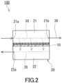
- a separation membrane 10 of the present embodiment includes a separation functional layer 1, an intermediate layer 2, and a porous support member 3.
- the intermediate layer 2 is disposed between the separation functional layer 1 and the porous support member 3, and is in direct contact with each of the separation functional layer 1 and the porous support member 3.
- the intermediate layer 2 is formed from an emulsion resin composition.
- the separation functional layer 1 is, for example, a layer capable of allowing an acid gas contained in a gas mixture to preferentially permeate therethrough.
- the separation functional layer 1 includes a resin.
- the resin included in the separation functional layer 1 include a polyether block amide resin, a polyamide resin, a polyether resin, a polyimide resin, a cellulose acetate resin, a silicone resin, and a fluorine resin.
- the separation functional layer 1 preferably includes a polyether block amide resin.
- the separation functional layer 1 is preferably composed substantially of a resin.
- the phrase "composed substantially of” means exclusion of other component that alters essential characteristics of a material referred to, and for example means that 95 wt% or more or even 99 wt% or more is composed of the material.
- the separation functional layer 1 may further include an additive, such as a leveling agent, besides the resin.
- the separation functional layer 1 includes an ionic liquid.
- the separation functional layer 1 includes, for example, a double-network gel including an ionic liquid.
- the double-network gel is a gel including two types of network structures independent from each other.
- the double-network gel includes, for example, a first network structure composed mainly of an organic material, a second network structure composed mainly of an inorganic material, and an ionic liquid.
- the phrase "composed mainly of” means that 50 wt% or more or even 70 wt% or more is composed of the material.
- the organic material for constituting the first network structure includes, for example, a polymer such as polyacrylamide (particularly, polydialkylacrylamide such as polydimethylacrylamide).
- the polymer included in the organic material may have a structural unit derived from an acrylamide derivative and may further include a cross-linked structure.
- the polymer including a cross-linked structure can be produced by a known method. First, a prepolymer having a structural unit having an N-hydroxysuccinimide ester group is prepared, for example. The structural unit having an N-hydroxysuccinimide ester group derives from N-acryloxysuccinimide, for example. Next, the prepolymer is allowed to react with an amine-based cross linking agent to obtain a polymer including a cross-linked structure.
- the amine-based cross linking agent is a compound, such as ethylene glycol bis(3-aminopropyl) ether, having two or more primary amino groups.
- the second network structure may include a network of a plurality of particles.
- the network of the plurality of particles are formed by, for example, the plurality of particles being bonded to each other by hydrogen bonds.
- the particles included in the second network structure may include an inorganic material.
- the particles included in the second network structure may include an organic material. Examples of the inorganic material included in the particles include silica, titania, and alumina. In one example, the particles included in the second network structure are silica particles.
- examples of the ionic liquid include an ionic liquid having: imidazolium, pyridinium, ammonium, or phosphonium; and a substituent having 1 or more carbon atoms.
- examples of the substituent having 1 or more carbon atoms include an alkyl group having 1 to 20 carbon atoms, a cycloalkyl group having 3 to 14 carbon atoms, and an aryl group having 6 to 20 carbon atoms, and these may be each further substituted by a hydroxy group, a cyano group, an amino group, a monovalent ether group, or the like (for example, a hydroxyalkyl group having 1 to 20 carbon atoms).
- alkyl group having 1 to 20 carbon atoms examples include a methyl group, an ethyl group, an n-propyl group, an n-butyl group, an n-pentyl group, an n-hexyl group, an n-heptyl group, an n-octyl group, an n-nonyl group, an n-decyl group, an n-undecyl group, an n-dodecyl group, an n-tridecyl group, an n-tetradecyl group, an n-pentadecyl group, an n-hexadecyl group, an n-heptadecyl group, an n-octadecyl group, an n-nonadecyl group, an n-eicosadecyl group, an i-propyl group, a sec-butyl group, an n
- the above alkyl group may be substituted by a cycloalkyl group.
- the number of carbon atoms in the alkyl group substituted by the cycloalkyl group is, for example, 1 or more and 20 or less.
- Examples of the alkyl group substituted by the cycloalkyl group include a cyclopropyl methyl group, a cyclobutyl methyl group, a cyclohexyl methyl group, and a cyclohexyl propyl group. These may be each further substituted by a hydroxy group, a cyano group, an amino group, a monovalent ether group, or the like.
- Examples of the cycloalkyl group having 3 to 14 carbon atoms include a cyclopropyl group, a cyclobutyl group, a cyclopentyl group, a cyclohexyl group, a cycloheptyl group, a cyclooctyl group, a cyclododecyl group, a norbornyl group, a bornyl group, and an adamantyl group. These may be each further substituted by a hydroxy group, a cyano group, an amino group, a monovalent ether group, or the like.
- aryl group having 6 to 20 carbon atoms examples include a phenyl group, a toluyl group, a xylyl group, a mesityl group, an anisyl group, a naphthyl group, and a benzyl group. These may be each further substituted by a hydroxy group, a cyano group, an amino group, a monovalent ether group, or the like.
- a compound having imidazolium and a substituent having 1 or more carbon atoms may further have a substituent such as an alkyl group, and may form a salt with a counter anion.
- the counter anion include alkyl sulfate, tosylate, methanesulfonate, acetate, bis(fluorosulfonyl)imide, bis(trifluoromethanesulfonyl)imide, thiocyanate, dicyanamide, tricyanomethanide, tetracyanoborate, hexafluorophosphate, tetrafluoroborate, and halide.
- preferred are bis(fluorosulfonyl)imide, bis(trifluoromethanesulfonyl)imide, dicyanamide, tricyanomethanide, and tetracyanoborate.
- the ionic liquid having imidazolium and a substituent having 1 or more carbon atoms include 1-ethyl-3-methylimidazolium bis(fluorosulfonyl)imide, 1-ethyl-3-methylimidazolium dicyanamide, 1-butyl-3-methylimidazolium bromide, 1-butyl-3-methylimidazolium chloride, 1-butyl-3-methylimidazolium tetrafluoroborate, 1-butyl-3-methylimidazolium hexafluorophosphate, 1-butyl-3-methylimidazolium trifluoromethanesulfonate, 1-butyl-3-methylimidazolium tetrachloroferrate, 1-butyl-3-methylimidazolium iodide, 1-butyl-2,3-dimethylimidazolium chloride, 1-butyl-2,3-dimethylimidazolium hexafluorophosphate,
- 1-ethyl-3-methylimidazolium bis(fluorosulfonyl)imide [EMI][FSI]
- 1-ethyl-3-methylimidazolium dicyanamide [EMI][DCA]
- 1-ethyl-3-methylimidazolium tricyanomethanide [EMI][TCM]
- 1-butyl-3-methylimidazolium bis(trifluoromethanesulfonyl)imide [C 4 mim][TF 2 N]
- 1-(2-hydroxyethyl)-3-methylimidazolium bis(trifluoromethanesulfonyl)imide [C 2 OHim][TF 2 N]
- the method for producing the double-network gel is not particularly limited, and for example, the method disclosed in E. Kamio et al., Adv.Mater, 29, 1704118 (2017 ) can be used.
- a content of the ionic liquid in the double-network gel is, for example, 50 wt% or more, preferably 60 wt% or more, more preferably 70 wt% or more, and still more preferably 80 wt% or more.
- the upper limit of the content of the ionic liquid is, for example, but not particularly limited to, 95 wt%.
- a content of the first network structure composed mainly of an organic material in the double-network gel is, for example, 1 wt% or more, preferably 5 wt% or more, and more preferably 10 wt% or more.
- the upper limit of the content of the first network structure is 15 wt%, for example.
- a content of the second network structure composed mainly of an inorganic material in the double-network gel is, for example, 1 wt% or more from the viewpoint of improving the strength of the double-network gel.
- the upper limit of the content of the second network structure is 5 wt%, for example.
- the ratio of the total value of the weight of the first network structure and the weight of the second network structure with respect to the weight of the double-network gel is, for example, 2 wt% or more, preferably 5 wt% or more, and more preferably 10 wt% or more. This ratio is preferably 20 wt% or less.
- the separation functional layer 1 is preferably composed substantially of the double-network gel.
- a thickness of the separation functional layer 1 is, for example, 50 ⁇ m or less, preferably 25 ⁇ m or less, and more preferably 15 ⁇ m or less. In some cases, the thickness of the separation functional layer 1 may be 10 ⁇ m or less, 5.0 ⁇ m or less, or 2.0 ⁇ m or less. The thickness of the separation functional layer 1 may be 0.05 ⁇ m or more, or 0.1 ⁇ m or more.
- the intermediate layer 2 is formed from an emulsion resin composition in the present embodiment.
- the emulsion resin composition means a liquid containing a dispersion medium and a polymer emulsified in the dispersion medium.
- the emulsion resin composition preferably includes water as a dispersion medium. That is, the emulsion resin composition is preferably an oil-in-water type (O/W type) emulsion.
- the emulsion resin composition may include, instead of or together with water, an organic solvent as a dispersion medium.
- organic solvent included in the emulsion resin composition examples include 2-ethylhexanol, butyl cellosolve, dipropylene glycol, ethylene glycol, propylene glycol, normal propyl alcohol, and isopropanol. From the viewpoint of dispersibility of the polymer in the emulsion resin composition, preferred are ethylene glycol and propylene glycol.
- the emulsion resin composition includes a silicone-based polymer, for example.
- the silicone-based polymer has, for example, a structural unit A represented by the following formula (1).
- R 1 and R 2 each are independently a hydrogen atom or a hydrocarbon group.
- the hydrocarbon group may be linear or branched.
- the number of carbon atoms in the hydrocarbon group is, for example, but not particularly limited to, 1 to 5, preferably 1 to 4, and more preferably 1 to 3.
- the hydrocarbon group is preferably an alkyl group that is linear or branched. Examples of the alkyl group include a methyl group, an ethyl group, an n-propyl group, an isopropyl group, an n-butyl group, an isobutyl group, a sec-butyl group, and a tert-butyl group.
- the hydrocarbon group may be an unsaturated hydrocarbon group such as a vinyl group.
- R 1 and R 2 each are preferably a hydrogen atom, a methyl group, an ethyl group, or a vinyl group.
- the number of the structural units A included in the silicone-based polymer is, for example, but not particularly limited to, 100 to 100000, preferably 200 to 90000, and more preferably 500 to 80000.
- the silicone-based polymer includes, for example, the structural unit A as a main component, and is preferably composed substantially of the structural unit A alone.
- the term "main component” means a structural unit having a largest content, on weight basis, of all the structural units constituting the silicone-based polymer.
- the silicone-based polymer may further include a structural unit other than the structural unit A.
- silicone-based polymer examples include dimethylpolysiloxane.
- the silicone-based polymer may be cyclosiloxane represented by the following formula (2).
- R 1 and R 2 are as described in the formula (1).
- the number n is, for example, but not particularly limited to, 100 to 100000, preferably 200 to 90000, and more preferably 500 to 80000.
- a weight-average molecular weight of the silicone-based polymer is, for example, but not particularly limited to, 1 ⁇ 10 4 to 1 ⁇ 10 6 .
- the silicone-based polymer is dispersed in the state of particles, for example.
- An average particle diameter of the silicone-based polymer is, for example, but not particularly limited to, 10 to 1000 nm, and preferably 50 to 800 nm.
- the average particle diameter means a median diameter determined by a particle size distribution that is measured based on a laser diffraction-scattering method with a particle size distribution measuring device.
- the average particle diameter of the silicone-based polymer can be measured by a method according to ISO 13320:2009 "Particle size analysis - Laser diffraction methods" by using a laser diffraction-scattering particle size distribution measuring device (LS13 320 available from Beckman Coulter, Inc., for example).
- the method for producing the emulsion resin composition including the silicone-based polymer is not particularly limited and known methods disclosed in JP 2004 339283 A and the like can be used suitably.
- the emulsion resin composition may further include a surfactant for dispersing the silicone-based polymer.
- a surfactant for dispersing the silicone-based polymer.
- the surfactant include an anionic surfactant such as alkyl sulfate, alkylbenzene sulfonate, or alkyl phosphate; a nonionic surfactant such as polyoxyethylene alkyl ether, polyoxyethylene alkyl phenyl ether, or polyoxyethylene fatty acid ester; a cationic surfactant such as quarternary ammonium salt, or alkylamine acetate; and an amphoteric surfactant such as alkylbetaine or alkylimidazoline.
- nonionic surfactant such as polyoxyethylene alkyl ether or polyoxyethylene alkyl phenyl ether.
- nonionic surfactants include polyoxyethylene octyl ether, polyoxyethylene nonyl ether, polyoxyethylene decyl ether, polyoxyethylene lauryl ether, polyoxyethylene tridecyl ether, polyoxyethylene myristyl ether, polyoxyethylene cetyl ether, polyoxyethylene stearyl ether, polyoxyethylene octylphenyl ether, polyoxyethylene nonylphenyl ether, and polyoxyethylene styrenated phenyl ether.
- One of these surfactants can be used alone or two or more of them can be used in combination.
- the emulsion resin composition may include a hydrophilic polymer instead of or together with the silicone-based polymer.
- hydrophilic polymer means a polymer having a contact angle of 100° or less, preferably 90° or less, and more preferably 85.2° or less with respect to water.
- the contact angle with respect to water can be determined by a sessile drop method specified in Japanese Industrial Standards (JIS) R3257:1999 by using a sheet composed of the polymer to be evaluated.
- JIS Japanese Industrial Standards
- the lower limit of the contact angle of the hydrophilic polymer with respect to water is, for example, but not particularly limited to, 30°, and may be 50° or 74.0°.
- the hydrophilic polymer includes, for example, at least one selected from the group consisting of a urethane-based polymer, a (meth)acrylic polymer, a (meth)acrylic urethane-based polymer, an ester-based polymer, and a vinyl ester-based polymer, and preferably includes a urethane-based polymer.
- urethane-based polymer examples include polyurethane obtained by a reaction between polyol and polyisocyanate, and a modified product of the polyurethane.
- the urethane-based polymer may be a urethane prepolymer having, at an end thereof, an isocyanate group or a blocked isocyanate group.
- polystyrene resin examples include: polyether polyols such as polyethylene glycol, polypropylene glycol, and polyoxy tetramethylene ether glycol or the like obtained by ring-opening polymerization of ethylene oxide, propylene oxide, tetrahydrofuran or the like, respectively; saturated or unsaturated low-molecular glycols such as ethylene glycol, diethylene glycol, triethylene glycol, 1,2-propanediol, 1,3-propanediol, 1,3-butanediol, 1,4-butanediol, neopentyl glycol, pentanediol, 3-methyl-1,5-pentanediol, 1,6-hexanediol, octanediol, 1,4-butynediol, dipropylene glycol, bisphenol A, a bisphenol A propylene oxide adduct, a bisphenol A ethylene
- polyols such as glycerin, trimethylolpropane, trimethylolethane, 1,2,6-hexanetriol, 1,2,4-butanetriol, pentaerythritol, and sorbitol can be used.
- the polyols preferably have a hydrophilic moiety such as an ethyleneoxide adduct.
- polyisocyanate aromatic, aliphatic, or alicyclic diisocyanates can be used.
- diisocyanates include 1,5-naphthylene diisocyanate, 4,4'-diphenylmethane diisocyanate, 4,4'-diphenyldimethylmethane diisocyanate, 4,4'-dibenzyl isocyanate, dialkyldiphenylmethane diisocyanate, tetraalkyldiphenylmethane diisocyanate, 1,3-phenylene diisocyanate, 1,4-phenylene diisocyanate, tolylene diisocyanate, butane-1,4-diisocyanate, hexamethylene diisocyanate, isopropylene diisocyanate, methylene diisocyanate, 2,2,4-trimethylhexamethylene diisocyanate, 2,4,4-trimethylhexamethylene diisocyanate, cyclohex
- Examples of a blocking agent for the isocyanate group include bisulfites, phenols including a sulfonic group, alcohols, lactams, oximes, and active methylene compounds.
- a hydrophilic group such as carboxylate, may be introduced into the urethane-based polymer in order to improve its dispersibility in the emulsion resin composition.
- the (meth)acrylic polymer has a structural unit derived from alkyl (meth)acrylate as a main component.
- (meth)acrylate means acrylate and/or methacrylate.
- alkyl group included in the alkyl (meth)acrylate is, for example, but not particularly limited to, a linear, branched, or cyclic alkyl group having 2 to 14 carbon atoms.
- alkyl (meth)acrylate examples include acrylic acid alkyl ester having an alkyl group having 2 to 14 carbon atoms, preferably acrylic acid alkyl ester having an alkyl group having 4 to 9 carbon atoms.
- acrylic acid alkyl ester examples include acrylic acid n-butyl, acrylic acid isobutyl, acrylic acid s-butyl, acrylic acid isoamyl, acrylic acid hexyl, acrylic acid heptyl, acrylic acid octyl, acrylic acid 2-ethylhexyl, acrylic acid isooctyl, acrylic acid nonyl, and acrylic acid isononyl.
- the alkyl (meth)acrylate may be, for example, methacrylic acid alkyl ester having an alkyl group having 2 to 14 carbon atoms, preferably methacrylic acid alkyl ester having an alkyl group having 2 to 10 carbon atoms.
- methacrylic acid alkyl ester examples include methacrylic acid ethyl, methacrylic acid propyl, methacrylic acid isopropyl, methacrylic acid n-butyl, methacrylic acid isobutyl, methacrylic acid s-butyl, methacrylic acid t-butyl, methacrylic acid 2-ethylhexyl, methacrylic acid cyclohexyl, methacrylic acid bornyl, and methacrylic acid isobornyl.
- alkyl (meth)acrylates can be used alone or two or more of them can be used in combination.
- a content of the structural unit derived from the alkyl (meth)acrylate in the (meth)acrylic polymer is, for example, but not particularly limited to, 70 to 100 wt%, preferably 85 to 99 wt%, and more preferably 87 to 99 wt%.
- the (meth)acrylic polymer may further include a structural unit derived from a copolymerizable monomer that is copolymerizable with the alkyl (meth)acrylate.
- the copolymerizable monomer include: a carboxyl group-containing monomer such as acrylic acid, methacrylic acid, carboxyethyl (meth)acrylate, carboxypentyl (meth)acrylate, itaconic acid, maleic acid, fumaric acid, or crotonic acid; alkyl (meth)acrylate having an alkyl group having 1 or 15 or more carbon atoms; (meth)acrylic acid aryl ester such as (meth)acrylic acid phenyl; vinyl ester such as vinyl acetate or vinyl propionate; a styrene-based monomer such as styrene; an epoxy group-containing monomer such as (meth)acrylic acid glycidyl or (meth)acrylic acid methylglycid
- Examples of the (meth)acrylic urethane-based polymer include a compound obtained by a reaction between (meth)acrylic polyol and polyisocyanate.
- Examples of the (meth)acrylic polyol include a (meth)acrylic polymer including a structural unit derived from hydroxyl group-containing (meth)acrylate.
- As the hydroxyl group-containing (meth)acrylate those stated above for the (meth)acrylic polymer can be mentioned.
- As the polyisocyanate those stated above for the urethane-based polymer can be mentioned.
- the polyisocyanate may be a urethane prepolymer having an isocyanate group.
- ester-based polymer examples include an ester-based polymer obtained by polycondensation of dicarboxylic acid and diol.
- dicarboxylic acid examples include: aromatic dicarboxylic acid such as phthalic acid, isophthalic acid, terephthalic acid, 2-methylterephthalic acid, 5-sulfoisophthalic acid, 4,4'-diphenyldicarboxylic acid, 4,4'-diphenyl ether dicarboxylic acid, 4,4'-diphenyl ketone dicarboxylic acid, 4,4'-difenoxicarboxylic acid, 4,4'-diphenyl sulfone dicarboxylic acid, 1,4-naphthalenedicarboxylic acid, 1,5-naphthalenedicarboxylic acid, 2,6-naphthalenedicarboxylic acid, or 2,7-naphthalenedicarboxylic acid; alicyclic dicarboxylic acid such as 1,2-cyclohexanedicar,
- diol examples include: aliphatic diol such as ethylene glycol, diethylene glycol, polyethylene glycol, propylene glycol, polypropylene glycol, 1,3-propanediol, 1,5-pentanediol, neopentyl glycol, 1,4-butanediol, 1,6-hexanediol, 1, 8-octanediol, or polyoxytetramethylene glycol; alicyclic diol such as 1,2-cyclohexanediol, 1,4-cyclohexanediol, 1,1-cyclohexanedimethylol, or 1,4-cyclohexanedimethylol; and aromatic diol such as xylylene glycol, 4,4'-dihydroxybiphenyl, 2,2-bis(4'-hydroxyphenyl)propane, or bis(4-hydroxyphenyl)sulfone.
- the vinyl ester-based polymer has, for example, a structural unit derived from vinyl ester.
- the vinyl ester include vinyl acetate and vinyl propionate.
- the vinyl ester-based polymer may further have a structural unit derived from olefin such as ethylene or propylene.
- a specific example of the vinyl ester-based polymer is an ethylene-vinyl acetate copolymer.
- a weight-average molecular weight of the hydrophilic polymer is, for example, but not particularly limited to, 1 ⁇ 10 4 to 1 ⁇ 10 7 .
- the hydrophilic polymer is dispersed in the state of particles, for example.
- An average particle diameter of the hydrophilic polymer is, for example, but not particularly limited to, 10 to 1000 nm, and preferably 50 to 800 nm.
- the average particle diameter of the hydrophilic polymer can be measured by the method mentioned above for the silicone-based polymer.
- the emulsion resin composition including the hydrophilic polymer can be produced by, for example, allowing a monomer component for forming the hydrophilic polymer to be subjected to emulsion polymerization under presence of an emulsifier (a surfactant).
- an emulsifier a surfactant
- the emulsion resin composition may further include a surfactant for dispersing the hydrophilic polymer.
- a surfactant for dispersing the hydrophilic polymer.
- the surfactant those stated above for the silicone-based polymer can be mentioned, for example.
- the emulsion resin composition may further include another surfactant different from the above-mentioned surfactants for dispersing respectively the silicone-based polymer and the hydrophilic polymer.
- the other surfactant can improve, depending on its type, wettability of the emulsion resin composition with respect to a metal roll included in a coater such as a gravure coater. Therefore, in the case where the emulsion resin composition includes the other surfactant, it tends to be possible to apply the emulsion resin composition uniformly by using the coater including a metal roll. The uniform application of the emulsion resin composition tends to make it possible to suppress variation in a thickness of the intermediate layer 2 formed from the emulsion resin composition.
- the other surfactant examples include a silicone-based surfactant.
- the silicone-based surfactant includes, for example, a modified polysiloxane having a hydrophilic group.
- Example of the hydrophilic group include a hydroxyl group, a carboxylic acid group, a sulfonic acid group, a (meth)acrylic group, an ester group, and an ether group.
- Specific examples of a modified group of the modified polysiloxane include -(CH 2 CH 2 O) n -R (n is an integer of 5 to 30, and R is a hydrogen atom or an alkyl group having 1 to 6 carbon atoms) and -(CH 2 CHOHCH 2 ) n -H (n is an integer of 5 to 30).
- modified polysiloxane examples include a polyether-modified product of polydimethylsiloxane.
- silicone-based surfactant examples include commercially available silicone-based surfactants such as "BYK” series available from BYK Japan KK, "Toray silicone” series available from Dow Corning Toray Co., Ltd., "TSF” series available from Momentive Performance Materials Japan LLC., and "KP” series and “KF” series available from Shin-Etsu Silicone.
- BYK-349 An example of the "BYK” series available from BYK Japan KK is BYK-349.
- BYK-349 tends to make it possible to suppress a decrease in permeation rate of carbon dioxide permeating through the intermediate layer 2.
- BYK-349 has high dispersibility in water and is thus suitable for the emulsion resin composition including water as a dispersion medium.
- the emulsion resin composition may further include a cross linking agent for crosslinking the silicone-based polymer and the hydrophilic polymer.
- the emulsion resin composition may include a water-insoluble cross linking agent for crosslinking the (meth)acrylic polymer having a structural unit derived from a carboxyl group-containing monomer.
- the water-insoluble cross linking agent is, for example, a water-insoluble compound having two or more (2 to 6, for example, and preferably 3 to 5) functional groups that can react with a carboxyl group.
- water-insoluble means that the weight in which a compound can be dissolved in 25°C, 100 parts by weight of water is 5 parts by weight or less, preferably 3 parts by mass or less, and still more preferably 2 parts by mass or less.
- the weight in which a compound can be dissolved in the water can be measured by the following method. First, water (25°C) and a compound both having the same weight are mixed and stirred at a rotation speed of 300 rpm for 10 minutes by using an agitator. The obtained mixture is divided into an aqueous phase and an oil phase by centrifugal separation. Next, the aqueous phase is taken out and dried at 120°C for 1 hour. From the loss in weight on drying, the weight of a nonvolatile substance in the aqueous phase (the weight in which the compound can be dissolved in 100 parts by weight of water) is calculated.
- Each of the functional groups that can react with a carboxyl group is, for example, but not particularly limited to, an epoxy group, an isocyanate group, and a carbodiimide group.
- an epoxy group preferred is an epoxy group.
- a glycidyl amino group is preferable from the viewpoint that it has a high reactivity and is thus unlikely to leave an unreacted substance from its crosslinking reaction, which is advantageous for low pollution property.
- an epoxy-based cross linking agent having an epoxy group is preferable, particularly, a cross linking agent having a glycidyl amino group (a glycidyl amino-based cross linking agent) is preferable.
- water-insoluble cross linking agent examples include: a glycidyl amino-based cross linking agent such as 1,3-bis(N,N-diglycidylaminomethyl)cyclohexane (a product named "TETRAD-C” available from MITSUBISHI GAS CHEMICAL COMPANY, INC., for example) [the weight in which the product can be dissolved in 25°C, 100 parts by weight of water is 2 parts by weight or less] or 1,3-bis(N,N-diglycidylaminomethyl)benzene (a product named "TETRAD-X” available from MITSUBISHI GAS CHEMICAL COMPANY, INC., for example) [the weight in which the product can be dissolved in 25°C, 100 parts by weight of water is 2 parts by weight or less]; and another epoxy-based cross linking agent such as Tris(2,3-epoxypropyl)isocyanurate (a product named "TEPIC-G” available from Nissan Chemical Corporation, for example) [the weight in
- the emulsion resin composition may further include a filler.
- a filler In the case where the intermediate layer 2 is formed from the emulsion resin composition including a filler, the permeation rate of carbon dioxide permeating through the intermediate layer 2 tends to be improved.
- the filler may include an inorganic material.
- the filler may include an organic material. Examples of the inorganic material included in the filler include zeolite and silica.
- the filler preferably has, for example, hydrophilicity and a high dispersibility in water.
- the filler has a particle shape, for example.
- An average particle diameter of the filler is smaller than the thickness of the intermediate layer 2 formed from the emulsion resin composition.
- the average particle diameter of the filler is, for example, 150 nm or less, and may be 100 nm or less or 50 nm or less.
- the lower limit of the average particle diameter of the filler is, for example, but not particularly limited to, 1 nm.
- the average particle diameter of the filler can be measured by the method mentioned above for the silicone-based polymer.
- the filler may have pores.
- An average pore diameter of the filler is, for example, but not particularly limited to, 0.1 nm to 5 nm.
- a density of the filler is, for example, but not particularly limited to, 0.5 to 5 g/cm 3 .
- the filler examples include "Zeoal” series available from Nakamura Choukou Co., Ltd. and "AEROSIL” series available from NIPPON AEROSIL CO., LTD.
- Examples of the “Zeoal” series available from Nakamura Choukou Co., Ltd. include Zeoal 4A 50nm and Zeoal ZSM-5. These fillers include zeolite.
- Examples of the "AEROSIL” series available from NIPPON AEROSIL CO., LTD. examples include AEROSILOX50. This filler includes silica. Zeoal 4A 50nm and AEROSILOX50 tend to have a higher hydrophilicity and a higher dispersibility in water than those of Zeoal ZSM-5.
- a solid content concentration of the emulsion resin composition is, for example, but not particularly limited to, 10 to 60 wt%.
- a ratio of a weight of the surfactant with respect to a weight of a total solid content in the emulsion resin composition is, for example, but not particularly limited to, 15 wt% or less, and may be 5 wt% or less or 1 wt% or less.
- the ratio of the weight of the surfactant is 15 wt% or less, it is possible, for example, to suppress sufficiently the entry of the emulsion resin composition into the porous support member 3 when the emulsion resin composition is applied onto the porous support member 3.
- the intermediate layer 2 can be produced by, for example, removing the dispersion medium from the emulsion resin composition. Accordingly, the intermediate layer 2 includes a component derived from the emulsion resin composition. In one example, the intermediate layer 2 includes at least one selected from the group consisting of a silicone-based polymer and a hydrophilic polymer, and preferably includes both a silicone-based polymer and a hydrophilic polymer. Note that the silicone-based polymer included in the intermediate layer 2 may be a compound obtained by crosslinking the silicone-based polymer included in the emulsion resin composition. Similarly, the hydrophilic polymer included in the intermediate layer 2 may be a compound obtained by crosslinking the hydrophilic polymer included in the emulsion resin composition.
- the separation membrane 10 including:
- a content of the silicone-based polymer in the intermediate layer 2 is, for example, but not particularly limited to, 10 wt% or more, preferably 30 wt% or more, more preferably 50 wt% or more, still more preferably 70 wt% or more, and particularly preferably 80 wt% or more, and it may be 90 wt% or more, 95 wt% or more, or 99 wt% or more.
- the intermediate layer 2 may be composed substantially of the silicone-based polymer. The higher the content of the silicone-based polymer in the intermediate layer 2 is, the higher a permeation rate of a permeated fluid from the separation membrane 10 tends to be. However, the content of the silicone-based polymer in the intermediate layer 2 may be less than 10 wt% or 5 wt% or less.
- the intermediate layer 2 may be substantially free of the silicone-based polymer.
- a content of the hydrophilic polymer in the intermediate layer 2 is, for example, but not particularly limited to, 1 wt% or more, preferably 5 wt% or more, and more preferably 10 wt% or more.
- the upper limit of the content of the hydrophilic polymer in the intermediate layer 2 is, for example, but not particularly limited to, 90 wt%, preferably 70 wt%, more preferably 50 wt%, still more preferably 30 wt%, and particularly preferably 20 wt%.
- the content of the hydrophilic polymer in the intermediate layer 2 be 10 wt% to 20 wt%. In some cases, however, the intermediate layer 2 may be composed substantially of the hydrophilic polymer or may be substantially free of the hydrophilic polymer.
- the intermediate layer 2 may further include a component other than the silicone-based polymer and the hydrophilic polymer.
- the other component include: a surfactant derived from the emulsion resin composition; and a filler. That is, the intermediate layer 2 may include a surfactant and may include a filler.
- the filler in the case where the intermediate layer 2 includes a filler, the filler is buried in a matrix including the silicone-based polymer or the hydrophilic polymer, and is preferably dispersed in the matrix. In the intermediate layer 2, the filler may aggregate partially.
- a content of the surfactant in the intermediate layer 2 is, for example, but not particularly limited to, 15 wt% or less, and may be 5 wt% or less or 1 wt% or less.
- the lower limit of the content of the surfactant is, for example, but not particularly limited to, 0.1 wt%.
- a content of the filler in the intermediate layer 2 is, for example, but not particularly limited to, 60 wt% or less, and may be 40 wt% or less, 20 wt% or less, or 10 wt% or less.
- the lower limit of the content of the filler is, for example, but not particularly limited to, 1 wt%.
- the thickness of the intermediate layer 2 is, for example, but not particularly limited to, less than 50 ⁇ m, preferably 40 ⁇ m or less, more preferably 30 ⁇ m or less, still more preferably 10 ⁇ m or less, and particularly preferably 5 ⁇ m or less.
- a smaller thickness of the intermediate layer 2 tends to make it possible to suppress a decrease in the permeation rate of the permeated fluid from the separation membrane 10.
- the lower limit of the thickness of the intermediate layer 2 is, for example, but not particularly limited to, 0.1 ⁇ m.
- the porous support member 3 supports the separation functional layer 1 via the intermediate layer 2.
- the porous support member 3 include: a nonwoven fabric; porous polytetrafluoroethylene; an aromatic polyamide fiber; a porous metal; a sintered metal; a porous ceramic; a porous polyester; porous nylon; an activated carbon fiber; latex; silicone; silicone rubber; a permeable (porous) polymer including at least one selected from the group consisting of polyvinyl fluoride, polyvinylidene fluoride, polyurethane, polypropylene, polyethylene, polycarbonate, polysulfone, polyether ether ketone, polyacrylonitrile, polyimide, and polyphenylene oxide; a metallic foam having an open cell or a closed cell; a polymer foam having an open cell or a closed cell; silica; a porous glass; and a mesh screen.
- the porous support member 3 may be a combination of two or more of these materials.
- the porous support member 3 has an average pore diameter of 0.01 to 0.4 ⁇ m, for example.
- a thickness of the porous support member 3 is, for example, but not particularly limited to, 10 ⁇ m or more, preferably 20 ⁇ m or more, and more preferably 50 ⁇ m or more.
- the thickness of the porous support member 3 is, for example, 300 ⁇ m or less, preferably 200 ⁇ m or less, and more preferably 150 ⁇ m or less.
- a method for manufacturing the separation membrane 10 of the present embodiment includes, for example: applying an emulsion resin composition onto the porous support member 3 and thereby forming a coating film; and drying the coating film and thereby forming the intermediate layer 2.
- the method for preparing the emulsion resin composition is not particularly limited.
- the emulsion resin composition may be prepared by adding a surfactant, a filler, etc. to an emulsion including a silicone-based polymer and/or a hydrophilic polymer.
- a slurry including a filler and a dispersion medium may be added to the emulsion.
- a slurry including a filler In the case where a slurry including a filler is added to the emulsion, aggregation of the filler tends to be suppressed in the obtained emulsion resin composition.
- the emulsion resin composition in which aggregation of the filler is suppressed makes it possible to suppress occurrence of a defect at the time of producing the intermediate layer 2.
- the method according to which the slurry including a filler is added to the emulsion also makes it possible to increase the content of the filler in the intermediate layer 2 easily.
- a surface of the porous support member 3 onto which the emulsion resin composition is applied preferably has a somewhat large contact angle with respect to water.
- the surface of the porous support member 3 having a large contact angle with respect to water is suitable for preventing the emulsion resin composition including water as a dispersion medium from entering into the porous support member 3.
- the contact angle of the surface of the porous support member 3 with respect to water is, for example, 60° or more, and preferably 70° or more.
- the upper limit of this contact angle is, for example, but not particularly limited to, 120°.
- the contact angle can be determined by a sessile drop method specified in JIS R3257:1999.
- the method for applying the emulsion resin composition is not particularly limited, and a method such as a spin coating method or a dip coating method can be used, for example.
- the emulsion resin composition may be applied, for example, using a wire bar.
- the method for applying the emulsion resin composition may be a method using a metal roll, such as a gravure coating method.
- the coating film can be dried under heating conditions, for example.
- the heating temperature of the coating film is, for example, 50°C or higher.
- the heating time of the coating film is, for example, one minute or longer, and may be five minutes or longer.
- the thickness of the intermediate layer 2 can be adjusted by, for example, the solid content concentration of the emulsion resin composition and a thickness of the coating film.
- a surface of the intermediate layer 2 can be subjected to an adhesion improvement treatment, if necessary.
- the adhesion improvement treatment is, for example, a surface treatment such as application of a primer, a corona discharge treatment, or a plasma treatment.
- a coating liquid containing the materials of the separation functional layer 1 is prepared.
- the coating liquid containing the materials of the separation functional layer 1 is applied onto the intermediate layer 2 to obtain a coating film.
- the coating film is dried to form the separation functional layer 1.
- the surface of the intermediate layer 2 onto which the coating liquid is applied preferably has a somewhat small contact angle with respect to water.
- the surface of the intermediate layer 2 having a small contact angle with respect to water is suitable for improving adhesion with the separation functional layer 1.
- the contact angle of the surface of the intermediate layer 2 with respect to water is, for example, 120° or less, and preferably 110° or less.
- the lower limit of this contact angle is, for example, but not particularly limited to, 70°.
- the contact angle can be determined by a sessile drop method specified in JIS R3257:1999.
- a peel strength P1 of the intermediate layer 2 with respect to the porous support member 3 is, for example, 0.1 N/18 mm or more, preferably 0.2 N/18 mm or more, more preferably 0.3 N/18 mm or more, still more preferably 0.4 N/18 mm or more, and particularly preferably 0.5 N/18 mm or more.
- the upper limit of the peel strength P1 is, for example, but not particularly limited to, 2.0 N/18 mm.
- the peel strength P1 can be measured by the following method. First, a laminate of the intermediate layer 2 and the porous support member 3 to be measured is cut into a piece that is 25 mm in width and 100 in length to obtain a specimen. Next, a single-sided adhesive tape (No.7235, 18 mm in width, available from Nitto Denko Corporation) is attached on the intermediate layer 2 included in the specimen, and a 2 kg roller is rolled thereon back and forth once so that they are press-bonded. Next, the intermediate layer 2 is peeled off, together with the single-sided adhesive tape, from the porous support member 3 at a peel angle of 90° and a peel rate of 300 mm/min by using a commercially available tensile testing machine. The peel strength at that time is determined as the peel strength P1. The above-mentioned measurement is made under a 23°C atmosphere.
- the method for applying the coating liquid and the drying conditions can be the same as the method and the conditions described above for the intermediate layer 2.
- the application of the coating liquid containing the materials of the separation functional layer 1 may be performed by a spin coating method.
- the separation functional layer 1 is formed on the intermediate layer 2 to obtain the separation membrane 10.
- the intermediate layer 2 is formed from the emulsion resin composition in the separation membrane 10 of the present embodiment.
- the polymer(s) included in the emulsion resin composition is unlikely to enter into the porous support member 3.
- the emulsion resin composition includes water as a dispersion medium and also the surface of the porous support member 3 has a large contact angle with respect to water, the entry of the polymer(s) into the porous support member 3 is suppressed significantly.
- the emulsion resin composition makes it possible to produce easily the intermediate layer 2 with a relatively small thickness while suppressing variation in the thickness.
- the formation of the separation functional layer 1 on the intermediate layer 2 formed from the emulsion resin composition tends to suppress variation in separation performance of the separation membrane 10.
- the separation membrane 10 allows, for example, an acid gas contained in a gas mixture to preferentially permeate therethrough.
- a permeation rate T1 of carbon dioxide permeating through the separation membrane 10 is, for example, 10 GPU or more, preferably 50 GPU or more, and more preferably 100 GPU or more.
- the upper limit of the permeation rate T1 is, for example, but not particularly limited to, 500 GPU.
- GPU means 10 -6 •cm 3 (STP)/(sec•cm 2 •cmHg).
- cm 3 (STP) means the volume of carbon dioxide at 1 atmospheric pressure and 0°C.
- the permeation rate T1 can be calculated by the following method. First, a gas mixture composed of carbon dioxide and nitrogen is supplied to a space adjacent to one surface (a principal surface 11, on the separation functional layer side, of the separation membrane 10, for example) of the separation membrane 10 while a space adjacent to another surface (a principal surface 12, on the porous support member side, of the separation membrane 10) of the separation membrane 10 is decompressed. Thereby, a permeated fluid that has permeated through the separation membrane 10 can be obtained. A weight of the permeated fluid as well as a volume ratio of carbon dioxide and a volume ratio of nitrogen in the permeated fluid are measured. From the measurement results, the permeation rate T1 can be calculated.
- a concentration of the carbon dioxide in the gas mixture is 50 vol% under standard conditions (0°C, 101 kPa).
- the gas mixture supplied to the space adjacent to the one surface of the separation membrane 10 has a temperature of 30°C and a pressure of 0.1 MPa.
- the space adjacent to the other surface of the separation membrane 10 is decompressed in such a manner that a pressure in the space is lower than an atmospheric pressure in a measurement environment by 0.1 MPa.
- a separation factor ⁇ 1 of the separation membrane 10 for carbon dioxide with respect to nitrogen is, for example, but not particularly limited to, 20 or more, and preferably 40 or more.
- the upper limit of the separation factor ⁇ 1 is, for example, but not particularly limited to, 100.
- a coefficient of variation of the permeation rate T1 of carbon dioxide permeating through the separation membrane 10 and a coefficient of variation of the separation factor ⁇ 1 of the separation membrane 10 for carbon dioxide with respect to nitrogen tend to be small.
- the coefficient of variation of the permeation rate T1 of carbon dioxide permeating through the separation membrane 10 is, for example, less than 0.18, preferably 0.15 or less, more preferably 0.10 or less, and still more preferably 0.05 or less.
- the lower limit of the coefficient of variation of the permeation rate T1 is, for example, but not particularly limited to, 0.001.
- the coefficient of variation of the permeation rate T1 can be determined by the following method. First, the separation membrane 10 is cut to prepare at least three specimens. Each of the specimens is measured for the permeation rate T1 for carbon dioxide by the above-mentioned method. An average value and a standard deviation of the obtained permeation rates T1 are calculated. The ratio of the standard deviation with respect to the average value can be considered as the coefficient of variation of the permeation rate T1.
- the coefficient of variation of the separation factor ⁇ 1 of the separation membrane 10 for carbon dioxide with respect to nitrogen is, for example, 0.50 or less, preferably 0.40 or less, more preferably 0.30 or less, still more preferably 0.20 or less, and particularly preferably 0.10 or less.
- the lower limit of the coefficient of variation of the separation factor ⁇ 1 is, for example, but not particularly limited to, 0.001.
- the coefficient of variation of the separation factor ⁇ 1 can be determined by the following method. First, the separation membrane 10 is cut to prepare at least three specimens. Each of the specimens is measured for the separation factor ⁇ 1 by the above-mentioned method. An average value and a standard deviation of the obtained separation factors ⁇ 1 are calculated. The ratio of the standard deviation with respect to the average value can be considered as the coefficient of variation of the separation factor ⁇ 1.
- a permeation rate T2 of carbon dioxide permeating through the intermediate layer 2 is, for example, 10 GPU or more, preferably 500 GPU or more, more preferably 1000 GPU or more, still more preferably 1100 GPU or more, particularly preferably 1500 GPU or more, and especially preferably 2000 GPU or more, and may be 3000 GPU or more.
- the upper limit of the permeation rate T2 is, for example, but not particularly limited to, 10000 GPU.
- the permeation rate T2 can be measured by the same method as that for the permeation rate T1, except that a laminate of the intermediate layer 2 and the porous support member 3 is used instead of the separation membrane 10.
- a separation factor ⁇ 2 of the intermediate layer 2 for carbon dioxide with respect to nitrogen is, for example, but not particularly limited to, 1 or more, and preferably 5 or more.
- the upper limit of the separation factor ⁇ 2 is, for example, but not particularly limited to, 20.
- the separation factor ⁇ 2 can be calculated by the same method as that for the separation factor ⁇ 1.
- the degree of variation in separation performance of the separation membrane 10 can be estimated from the degree of variation in separation performance of the intermediate layer 2. That is, the more the variation in separation performance of the intermediate layer 2 is suppressed, the more the variation in separation performance of the separation membrane 10 tends to be suppressed.
- a coefficient of variation of the permeation rate T2 of carbon dioxide permeating through the intermediate layer 2 is, for example, 0.50 or less, preferably 0.40 or less, more preferably 0.30 or less, still more preferably 0.20 or less, and particularly preferably 0.15 or less.
- the lower limit of the coefficient of variation of the permeation rate T2 is, for example, but not particularly limited to, 0.001.
- the coefficient of variation of the permeation rate T2 can be determined by the same method as that for the coefficient of variation of the permeation rate T1, except that a laminate of the intermediate layer 2 and the porous support member 3 is used instead of the separation membrane 10.
- the separation factor ⁇ 2 of the intermediate layer 2 for carbon dioxide with respect to nitrogen is, for example, 0.40 or less, preferably 0.30 or less, more preferably 0.20 or less, and still more preferably 0.10 or less.
- the lower limit of the coefficient of variation of the separation factor ⁇ 2 is, for example, but not particularly limited to, 0.001.
- the coefficient of variation of the separation factor ⁇ 2 can be determined by the same method as that for the coefficient of variation of the separation factor ⁇ 1, except that a laminate of the intermediate layer 2 and the porous support member 3 is used instead of the separation membrane 10.
- a peel strength P2 of the separation functional layer 1 with respect to the intermediate layer 2 is, for example, but not particularly limited to, 0.4 N/10 mm or more, preferably 1.0 N/10 mm or more, more preferably 2.0 N/10 mm or more, still more preferably 3.0 N/10 mm or more, and particularly preferably 4.0 N/10 mm or more.
- a larger peel strength P2 tends make it possible to suppress peeling of the separation functional layer 1 from the intermediate layer 2 at the time when, for example, the separation membrane 10 is being used.
- the upper limit of the peel strength P2 is, for example, but not particularly limited to, 10.0 N/10 mm.
- the peel strength P2 of the separation functional layer 1 with respect to the intermediate layer 2 can be adjusted by, for example, the type and content of the hydrophilic polymer included in the intermediate layer 2.
- the peel strength P2 can be measured by the following method. First, the separation membrane 10 to be measured is cut into a piece that is 10 mm in width and 50 mm in length to obtain a specimen. Next, a surface of the separation functional layer 1 included in the specimen is entirely laid on a polyethylene terephthalate film via a double-sided adhesive tape (No. 500 available from Nitto Denko Corporation), and a 2 kg roller is rolled thereon back and forth once so that they are press-bonded. Next, the separation functional layer 1 is peeled off, together with the film, from the intermediate layer 2 at a peel angle of 90° and a peel rate of 300 mm/min by using a commercially available tensile testing machine. The peel strength at that time is determined as the peel strength P2.
- the above-mentioned measurement is made under a 23°C atmosphere.
- the double-sided adhesive tape (No. 500) used for the measurement of the peel strength P2 has an adhesive strength higher than that of the single-sided adhesive tape (No. 7235) used for the measurement of the peel strength P1.
- the separation membrane 10 of the present embodiment there can be mentioned the use for separating an acid gas from a gas mixture containing the acid gas.
- the acid gas in the gas mixture is, for example, carbon dioxide, hydrogen sulfide, carbonyl sulfide, sulfur oxide (SOx), hydrogen cyanide, and nitrogen oxide (NOx), and is preferably carbon dioxide.
- the gas mixture contains a gas other than the acid gas.
- the other gas is, for example, a nonpolar gas such as hydrogen or nitrogen or an inert gas such as helium, and is preferably nitrogen.
- the separation membrane 10 of the present embodiment is suitably used for separating carbon dioxide from a gas mixture containing carbon dioxide and nitrogen.
- the use of the separation membrane 10 is not limited to the use for separating an acid gas from the above-mentioned gas mixture.
- a membrane separation device 100 of the present embodiment includes the separation membrane 10 and a tank 20.
- the tank 20 includes a first chamber 21 and a second chamber 22.
- the separation membrane 10 is disposed in the tank 20.
- the separation membrane 10 separates the first chamber 21 and the second chamber 22 from each other.
- the separation membrane 10 extends from one of a pair of wall surfaces of the tank 20 to the other.
- the first chamber 21 has an inlet 21a and an outlet 21b.
- the second chamber 22 has an outlet 22a.
- the inlet 21a, the outlet 21b, and the outlet 22a each are, for example, an opening provided in the wall surfaces of the tank 20.
- Membrane separation using the membrane separation device 100 is performed by the following method, for example.
- a gas mixture 30 containing an acid gas is supplied to the first chamber 21 via the inlet 21a.
- a concentration of the acid gas in the gas mixture 30 is, for example, but not particularly limited to, 0.01 vol% (100 ppm) or more, preferably 1 vol% or more, more preferably 10 vol% or more, still more preferably 30 vol% or more, and particularly preferably 50 vol% or more, under standard conditions.
- the upper limit of the concentration of the acid gas in the gas mixture 30 is, for example, but not particularly limited to, 90 vol% under standard conditions.
- a pressure in the first chamber 21 may be increased by supplying the gas mixture 30.
- the membrane separation device 100 may further include a pump (not shown) for increasing a pressure of the gas mixture 30.
- the pressure of the gas mixture 30 to be supplied to the first chamber 21 is, for example, 0.1 MPa or more, and preferably 0.3 MPa or more.
- a pressure in the second chamber 22 may be decreased while the gas mixture 30 is supplied to the first chamber 21.
- the membrane separation device 100 may further include a pump (not shown) for decreasing the pressure in the second chamber 22.
- the pressure in the second chamber 22 may be decreased such that a space in the second chamber 22 has a pressure lower than an atmospheric pressure in a measurement environment by, for example, 10 kPa or more, preferably 50 kPa or more, and more preferably 100 kPa or more.
- Supply of the gas mixture 30 to the first chamber 21 allows to obtain, on the other surface side of the separation membrane 10, a permeated fluid 35 having a content of an acid gas higher than that in the gas mixture 30. That is, the permeated fluid 35 is supplied to the second chamber 22.
- the permeated fluid 35 contains, for example, an acid gas as a main component.
- the permeated fluid 35 may contain a small amount of a gas other than the acid gas.
- the permeated fluid 35 is discharged outside the tank 20 via the outlet 22a.
- the concentration of the acid gas in the gas mixture 30 gradually decreases from the inlet 21a toward the outlet 21b in the first chamber 21.
- the gas mixture 30 processed in the first chamber 21 (a non-permeated fluid 36) is discharged outside the tank 20 via the outlet 21b.
- the membrane separation device 100 of the present embodiment is suitable for a flow-type (continuous-type) membrane separation method.
- the membrane separation device 100 of the present embodiment may be used for a batch-type membrane separation method.
- a membrane separation device 110 of the present embodiment includes a central tube 41 and a laminate 42.
- the laminate 42 includes the separation membrane 10.
- the membrane separation device 110 is a spiral membrane element.
- the central tube 41 has a cylindrical shape.
- the central tube 41 has, in a surface thereof, a plurality of holes for allowing the permeated fluid 35 to flow into the central tube 41.
- Examples of a material of the central tube 41 include: a resin such as an acrylonitrile-butadiene-styrene copolymer resin (ABS resin), a polyphenylene ether resin (PPE resin), or a polysulfone resin (PSF resin); and a metal such as stainless steel or titanium.
- the central tube 41 has an inner diameter in a range of 20 to 100 mm, for example.
- the laminate 42 further includes a supply-side flow passage material 43 and a permeation-side flow passage material 44 in addition to the separation membrane 10.
- the laminate 42 is wound around the central tube 41.
- the membrane separation device 110 may further include an exterior material (not shown).
- a resin net composed of polyphenylene sulfide (PPS) or an ethylene-chlorotrifluoroethylene copolymer (ECTFE) can be used as the supply-side flow passage material 43 and the permeation-side flow passage material 44.
- PPS polyphenylene sulfide
- ECTFE ethylene-chlorotrifluoroethylene copolymer
- Membrane separation using the membrane separation device 110 is performed by the following method, for example.
- the permeated fluid 35 that has permeated through the separation membrane 10 of the laminate 42 moves into the central tube 41.
- the permeated fluid 35 is discharged outside via the central tube 41.
- the gas mixture 30 processed by the membrane separation device 110 (the non-permeated fluid 36) is discharged outside from another end of the wound laminate 42.
- the acid gas can be separated from the gas mixture 30.
- a UF membrane (ultrafiltration membrane) RS-50 (a laminate of a PVDF porous layer and a PET nonwoven fabric) available from Nitto Denko Corporation was used.
- the coating film was formed on the PVDF porous layer of the RS-50.
- the obtained coating film was dried at 130°C for 10 minutes to form an intermediate layer with a thickness of 1 ⁇ m.
- the content of the silicone-based polymer was 90 parts by weight and the content of the urethane-based polymer was 10 parts by weight.
- a polyether block amide resin (Pebax MH1657 available from Arkema) was put in a mixed solution of 24.0 g of isopropanol and 10.3 g of water and the resultant mixture was stirred at 80°C for 3 hours to produce 35.0 g of a coating liquid containing the polyether block amide resin at a concentration of 2 wt%.
- the coating liquid contained 0.01 g of a leveling agent (KP-112 available from Shin-Etsu Chemical Co., Ltd.).
- an applicator gap: 50 ⁇ m
- the produced coating liquid was applied onto the intermediate layer to obtain a coating film.
- the obtained coating film was dried in an oven at 60°C for 30 minutes to form a separation functional layer.
- a separation membrane of Example 1 was obtained.
- Separation membranes of Examples 2 to 22 were obtained in the same manner as in Example 1, except that the type of the hydrophilic polymer and the contents of the polymers in the intermediate layer were changed as shown in Tables 1 and 2.
- a separation membrane of Example 23 was obtained in the same manner as in Example 1, except that the emulsion resin composition was free of the hydrophilic polymer, the content of the silicone-based polymer in the intermediate layer was changed to 100 parts by weight, and a surface of the intermediate layer was subjected to a corona treatment before the separation functional layer was formed thereon.
- a laminate of Reference Example 1 was obtained in the same manner as in Example 23, except that the surface of the intermediate layer was subjected to no corona treatment and the separation functional layer was omitted.
- a separation membrane of Comparative Example 1 was obtained in the same manner as in Example 23, except that a solution (YSR-3022 available from Momentive Performance Materials Inc.) containing a silicone-based polymer was used instead of the emulsion resin composition and the content of the silicone-based polymer in the intermediate layer was changed to 88 parts by weight. Note that the solution containing the silicone-based polymer further contained a curing catalyst and a curing retardant, so that a cure reaction of the silicone-based polymer proceeded when the intermediate layer was produced.
- a solution YSR-3022 available from Momentive Performance Materials Inc.
- a laminate of Reference Example 2 was obtained in the same manner as in Comparative Example 1, except that the surface of the intermediate layer was subjected to no corona treatment and the separation functional layer was omitted.
- aqueous emulsion POLON-MF-56 available from Shin-Etsu Chemical Co., Ltd.
- a silicone-based polymer 1.2 g
- an aqueous slurry including a filler 1.2 g
- 18.1 g of ion exchange water for dilution were mixed to produce 20.0 g of an emulsion resin composition having a solid content concentration of 2 wt%.
- a zeolite aqueous slurry Zeoal 4A 50 nm aqueous slurry available from Nakamura Choukou Co., Ltd.
- the produced emulsion resin composition was applied onto a porous support member to obtain a coating film.
- a porous support member a UF membrane (ultrafiltration membrane) RS-50 (a laminate of a PVDF porous layer and a PET nonwoven fabric) available from Nitto Denko Corporation was used.
- the coating film was formed on the PVDF porous layer of the RS-50.
- the obtained coating film was dried at 130°C for 10 minutes to form an intermediate layer with a thickness of 2 ⁇ m.
- the content of the silicone-based polymer was 70 parts by weight and the content of the filler was 30 parts by weight.
- a polyether block amide resin (Pebax MH1657 available from Arkema) was put in a mixed solution of 24.0 g of isopropanol and 10.3 g of water and the resultant mixture was stirred at 80°C for 3 hours to produce 35.0 g of a coating liquid containing the polyether block amide resin at a concentration of 2 wt%.
- the coating liquid contained 0.01 g of a leveling agent (KP-112 available from Shin-Etsu Chemical Co., Ltd.).
- an applicator gap: 50 ⁇ m
- the produced coating liquid was applied onto the intermediate layer to obtain a coating film.
- the obtained coating film was dried in an oven at 60°C for 30 minutes to form a separation functional layer.
- a separation membrane of Example 24 was obtained.
- Separation membranes of Examples 25 and 26 were obtained in the same manner as in Example 24, except that the type of the filler and the contents of the polymer and filler in the intermediate layer were changed as shown in Table 4.
- water is added to a surfactant to dilute it by a factor of 100.
- As the surfactant BYK-347 available from BYK Japan KK was used.
- a gravure coater gap: 5 ⁇ m
- the produced emulsion resin composition was applied onto a porous support member to obtain a coating film.
- the coating film had a thickness (a coating thickness) of 5 ⁇ m.
- a UF membrane (ultrafiltration membrane) RS-50 a laminate of a PVDF porous layer and a PET nonwoven fabric available from Nitto Denko Corporation was used.
- the coating film was formed on the PVDF porous layer of the RS-50.
- the obtained coating film was dried at 130°C for 2.5 minutes to form an intermediate layer with a thickness of 0.5 ⁇ m.
- the content of the silicone-based polymer was 100 parts by weight and the content of the surfactant was 5 parts by weight.
- a polyether block amide resin (Pebax MH1657 available from Arkema) was put in a mixed solution of 129 g of isopropanol and 441 g of water and the resultant mixture was stirred at 80°C for 3 hours to produce 1500 g of a coating liquid containing the polyether block amide resin at a concentration of 2 wt%.
- the coating liquid contained 0.3 g of a leveling agent (KP-112 available from Shin-Etsu Chemical Co., Ltd.).
- an applicator gap: 50 ⁇ m
- the produced coating liquid was applied onto the intermediate layer to obtain a coating film.
- the obtained coating film was dried in an oven at 80°C for 2.5 minutes to form a separation functional layer.
- a separation membrane of Example 27 was obtained.
- a laminate of Reference Example 3 was obtained in the same manner as in Example 23, except that the gap of the applicator at the time of forming the intermediate layer was set to 100 ⁇ m, the surface of the intermediate layer was subjected to no corona treatment and the separation functional layer was omitted.
- the separation performance of the intermediate layer was evaluated by the following method. First, a laminate of the intermediate layer and the porous support member obtained before the separation functional layer was formed thereon was cut to prepare three specimens. Each of the specimens was measured for the separation factor ⁇ 2 for carbon dioxide with respect to nitrogen (CO 2 /N 2 ) and the permeation rate T2 of carbon dioxide. Specifically, the specimen was placed in a metal cell, and the metal cell was sealed with an O-ring so that no leakage would occur. Next, a gas mixture was injected into the metal cell such that the gas mixture was in contact with a principal surface, on the intermediate layer side, of the specimen. The gas mixture was composed substantially of carbon dioxide and nitrogen.
- the concentration of carbon dioxide in the gas mixture was 50 vol% under standard conditions.
- the gas mixture injected into the metal cell had a temperature of 30°C and a pressure of 0.1 MPa.
- a space, in the metal cell, that is adjacent to a principal surface, on the porous support member side, of the specimen was decompressed using a vacuum pump. This space was decompressed in such a manner that a pressure in the space was lower than an atmospheric pressure in a measurement environment by 0.1 kPa. Thus, a permeated fluid was obtained.
- the separation factor ⁇ 2 as well as the permeation rate T2 of the carbon dioxide of the specimen were calculated based on the composition of the obtained permeated fluid, the weight of the permeated fluid, etc.
- the coefficient of variation of the separation factor ⁇ 2 and the coefficient of variation of the permeation rate T2 were determined.
- the coefficient of variation of the separation factor ⁇ 2 as well as the coefficient of variation of the permeation rate T2 of the intermediate layer were 0.20 or less.
- the coefficient of variation of the separation factor ⁇ 2 as well as the coefficient of variation of the permeation rate T2 of the intermediate layer were 0.50 or more, which significantly exceeded 0.20.
- Tables 1 to 4 show the average value of the obtained separation factors ⁇ 2 and the average value of the permeation rates T2.
- the separation performance of the separation membrane was also evaluated.
- the evaluation on the separation performance of the separation membrane was conducted by the same method as that for the evaluation on the separation performance of the intermediate layer, except that the separation membrane was used instead of the laminate of the intermediate layer and the porous support member.
- Three specimens prepared by cutting the separation membrane were measured for the separation factor ⁇ 1 for carbon dioxide with respect to nitrogen (CO 2 /N 2 ) and the permeation rate T1 of carbon dioxide.
- Table 5 shows the average value and coefficient of variation of the obtained separation factors ⁇ 1 and permeation rates T1.
- Table 5 also shows the average value and coefficient of variation of the separation factors ⁇ 2 and permeation rates T2 of the intermediate layer in each of Examples 1, 4 and 24 to 27, Comparative Example 1, and Reference Example 2.
- FIG. 4A shows the result. As can be seen from FIG. 4A , a defect (pinhole) was caused on the surface of the intermediate layer in Comparative Example 1.
- FIG. 4B shows the result.
- forming the separation functional layer on the intermediate layer having the defect also caused a defect in the separation functional layer.
- Example 1 2 3 4 5 6 7 8 9 10 Silicone-based polymer (parts by weight) MF-56 (aqueous emulsion) 90 90 90 90 90 90 90 90 90 90 90 90 90 80 YSR-3022 (solution) Urethane-based polymer R-2170 (aqueous emulsion) 10 20 DA200 (aqueous emulsion) 10 SF470 (aqueous emulsion) 10 WLS213 (aqueous emulsion) 10 SF420 (aqueous emulsion) 10 Intermediate layer Hydrophilic polymer (parts by weight) (Meth)acrylic polymer AP4690N (aqueous emulsion) 10 (Meth)acrylic urethane-based polymer WHW-822 (aqueous emulsion) 10 Ester-based polymer KT-8803 (aqueous emulsion) 10 Vinyl ester-based polymer EVA P-3N (aqueous emulsion) 10 Corona treatment Not provided Not provided Not provided Not provided Not provided Not
- the coefficient of variation of the separation factor ⁇ 2 and the coefficient of variation of the permeation rate T2 of the intermediate layer in each of Examples 1 to 27 were 0.20 or less, which was smaller than in Comparative Example 1. Furthermore, as can be seen from Table 5, the coefficient of variation of the separation factor ⁇ 1 and the coefficient of variation of the permeation rate T1 of the separation membrane in each of Examples 1, 4, and 24 to 27, in which the variation in separation performance of the intermediate layer was suppressed, tended to be smaller than in Comparative Example 1. From the results of Table 5, it can be inferred that the variation in separation performance of the separation membrane is more suppressed also in the other Examples than in Comparative Example 1. Note that as can be seen from Examples 24 to 26, the intermediate layer in each of those Examples, which contained a filler, tended to have the permeation rate T2 of carbon dioxide higher than that of the intermediate layer in Reference Example 3.
- the separation membrane of the present embodiment is suitable for separating an acid gas from a gas mixture containing the acid gas.
- the separation membrane of the present embodiment is suitable for separating carbon dioxide from an off-gas of a chemical plant or a thermal power plant.
Landscapes
- Chemical & Material Sciences (AREA)
- Chemical Kinetics & Catalysis (AREA)
- Engineering & Computer Science (AREA)
- Analytical Chemistry (AREA)
- General Chemical & Material Sciences (AREA)
- Oil, Petroleum & Natural Gas (AREA)
- Compositions Of Macromolecular Compounds (AREA)
Abstract
The present invention provides a separation membrane suitable for suppressing variation in separation performance. A separation membrane 10 of the present invention includes a separation functional layer 1, a porous support member 3 supporting the separation functional layer 1, and an intermediate layer 2 that is disposed between the separation functional layer 1 and the porous support member 3 and is formed from an emulsion resin composition. The emulsion resin composition includes, for example, a silicone-based polymer, a hydrophilic polymer, etc.
Description
- The present invention relates to a separation membrane and a method for manufacturing the same.
- A membrane separation method has been developed as a method for separating an acid gas such as carbon dioxide from a gas mixture containing the acid gas. The membrane separation method allows an efficient separation of an acid gas with a suppressed operation cost, compared with an absorption method according to which an acid gas contained in a gas mixture is absorbed by an absorbent to be separated.
- Separation membranes used in the membrane separation method include a composite membrane in which a separation functional layer is formed on a porous support member. In the field of separation membranes, an intermediate layer may be disposed between the separation functional layer and the porous support member in order to reduce the membrane thickness of the separation functional layer (
Patent Literatures -
- Patent Literature 1:
JP 6186286 B - Patent Literature 2:
JP 2019-209274 A - Conventional separation membranes are required to have suppressed variation in separation performance among different measurement points.
- Therefore, the present invention provides a separation membrane suitable for suppressing variation in separation performance.
- An intermediate layer can be produced by, for example, applying a solution containing a material of the intermediate layer onto a porous support member and drying the obtained coating film. However, according to studies by the present inventors, the above-mentioned solution applied onto the porous support member tends to enter into the porous support member. The entry of the solution into the porous support member causes not only variation in the thickness of the intermediate layer but also a defect in the formed intermediate layer. The present inventors have newly found that variation occurs in separation performance of a separation membrane when a separation functional layer is further formed on the intermediate layer formed by the above-mentioned method, and they have completed the present invention.
- The present invention provides a separation membrane including:
- a separation functional layer;
- a porous support member supporting the separation functional layer; and
- an intermediate layer that is disposed between the separation functional layer and the porous support member and is formed from an emulsion resin composition.
- The present invention further provides a method for manufacturing a separation membrane including a separation functional layer, a porous support member supporting the separation functional layer, and an intermediate layer that is disposed between the separation functional layer and the porous support member, the method including:
- applying an emulsion resin composition onto the porous support member and thereby forming a coating film; and
- drying the coating film and thereby forming the intermediate layer.
- The present invention further provides a separation membrane including:
- a separation functional layer;
- a porous support member supporting the separation functional layer; and
- an intermediate layer that is disposed between the separation functional layer and the porous support member and includes a silicone-based polymer and a hydrophilic polymer.
- The present invention can provide a separation membrane suitable for suppressing variation in separation performance.
-
-
FIG. 1 is a cross-sectional view illustrating schematically a separation membrane according to one embodiment of the present invention. -
FIG. 2 is a schematic cross-sectional view of a membrane separation device including the separation membrane of the present invention. -
FIG. 3 is a perspective view schematically showing a modification of the membrane separation device including the separation membrane of the present invention. -
FIG. 4A is an electron microscope image of a surface of an intermediate layer before a separation functional layer is formed thereon in a separation membrane of Comparative Example 1. -
FIG. 4B is an image showing a state after a coloring liquid is applied onto the separation functional layer of the separation membrane of Comparative Example 1. - The present invention will be described in detail below. The following description is not intended to limit the present invention to a specific embodiment.
- As shown in
FIG. 1 , aseparation membrane 10 of the present embodiment includes a separationfunctional layer 1, anintermediate layer 2, and aporous support member 3. Theintermediate layer 2 is disposed between the separationfunctional layer 1 and theporous support member 3, and is in direct contact with each of the separationfunctional layer 1 and theporous support member 3. Theintermediate layer 2 is formed from an emulsion resin composition. - The separation
functional layer 1 is, for example, a layer capable of allowing an acid gas contained in a gas mixture to preferentially permeate therethrough. In a preferred embodiment, the separationfunctional layer 1 includes a resin. Examples of the resin included in the separationfunctional layer 1 include a polyether block amide resin, a polyamide resin, a polyether resin, a polyimide resin, a cellulose acetate resin, a silicone resin, and a fluorine resin. The separationfunctional layer 1 preferably includes a polyether block amide resin. In this embodiment, the separationfunctional layer 1 is preferably composed substantially of a resin. In the present description, the phrase "composed substantially of" means exclusion of other component that alters essential characteristics of a material referred to, and for example means that 95 wt% or more or even 99 wt% or more is composed of the material. Note that the separationfunctional layer 1 may further include an additive, such as a leveling agent, besides the resin. - In another preferred embodiment, the separation
functional layer 1 includes an ionic liquid. The separationfunctional layer 1 includes, for example, a double-network gel including an ionic liquid. The double-network gel is a gel including two types of network structures independent from each other. The double-network gel includes, for example, a first network structure composed mainly of an organic material, a second network structure composed mainly of an inorganic material, and an ionic liquid. In the present description, the phrase "composed mainly of" means that 50 wt% or more or even 70 wt% or more is composed of the material. - The organic material for constituting the first network structure includes, for example, a polymer such as polyacrylamide (particularly, polydialkylacrylamide such as polydimethylacrylamide). The polymer included in the organic material may have a structural unit derived from an acrylamide derivative and may further include a cross-linked structure. The polymer including a cross-linked structure can be produced by a known method. First, a prepolymer having a structural unit having an N-hydroxysuccinimide ester group is prepared, for example. The structural unit having an N-hydroxysuccinimide ester group derives from N-acryloxysuccinimide, for example. Next, the prepolymer is allowed to react with an amine-based cross linking agent to obtain a polymer including a cross-linked structure. The amine-based cross linking agent is a compound, such as ethylene glycol bis(3-aminopropyl) ether, having two or more primary amino groups.
- The second network structure may include a network of a plurality of particles. The network of the plurality of particles are formed by, for example, the plurality of particles being bonded to each other by hydrogen bonds. The particles included in the second network structure may include an inorganic material. The particles included in the second network structure may include an organic material. Examples of the inorganic material included in the particles include silica, titania, and alumina. In one example, the particles included in the second network structure are silica particles.
- In the present embodiment, examples of the ionic liquid include an ionic liquid having: imidazolium, pyridinium, ammonium, or phosphonium; and a substituent having 1 or more carbon atoms.
- In an ionic liquid having imidazolium and a substituent having 1 or more carbon atoms, examples of the substituent having 1 or more carbon atoms include an alkyl group having 1 to 20 carbon atoms, a cycloalkyl group having 3 to 14 carbon atoms, and an aryl group having 6 to 20 carbon atoms, and these may be each further substituted by a hydroxy group, a cyano group, an amino group, a monovalent ether group, or the like (for example, a hydroxyalkyl group having 1 to 20 carbon atoms).
- Examples of the alkyl group having 1 to 20 carbon atoms include a methyl group, an ethyl group, an n-propyl group, an n-butyl group, an n-pentyl group, an n-hexyl group, an n-heptyl group, an n-octyl group, an n-nonyl group, an n-decyl group, an n-undecyl group, an n-dodecyl group, an n-tridecyl group, an n-tetradecyl group, an n-pentadecyl group, an n-hexadecyl group, an n-heptadecyl group, an n-octadecyl group, an n-nonadecyl group, an n-eicosadecyl group, an i-propyl group, a sec-butyl group, an i-butyl group, a 1-methylbutyl group, a 1-ethylpropyl group, a 2-methylbutyl group, an i-pentyl group, a neopentyl group, a 1,2-dimethylpropyl group, a 1,1-dimethylpropyl group, a t-pentyl group, a 2-ethylhexyl group, and a 1 ,5-dimethylhexyl group. These may be each further substituted by a hydroxy group, a cyano group, an amino group, a monovalent ether group, or the like.
- The above alkyl group may be substituted by a cycloalkyl group. The number of carbon atoms in the alkyl group substituted by the cycloalkyl group is, for example, 1 or more and 20 or less. Examples of the alkyl group substituted by the cycloalkyl group include a cyclopropyl methyl group, a cyclobutyl methyl group, a cyclohexyl methyl group, and a cyclohexyl propyl group. These may be each further substituted by a hydroxy group, a cyano group, an amino group, a monovalent ether group, or the like.
- Examples of the cycloalkyl group having 3 to 14 carbon atoms include a cyclopropyl group, a cyclobutyl group, a cyclopentyl group, a cyclohexyl group, a cycloheptyl group, a cyclooctyl group, a cyclododecyl group, a norbornyl group, a bornyl group, and an adamantyl group. These may be each further substituted by a hydroxy group, a cyano group, an amino group, a monovalent ether group, or the like.
- Examples of the aryl group having 6 to 20 carbon atoms include a phenyl group, a toluyl group, a xylyl group, a mesityl group, an anisyl group, a naphthyl group, and a benzyl group. These may be each further substituted by a hydroxy group, a cyano group, an amino group, a monovalent ether group, or the like.
- A compound having imidazolium and a substituent having 1 or more carbon atoms may further have a substituent such as an alkyl group, and may form a salt with a counter anion. Examples of the counter anion include alkyl sulfate, tosylate, methanesulfonate, acetate, bis(fluorosulfonyl)imide, bis(trifluoromethanesulfonyl)imide, thiocyanate, dicyanamide, tricyanomethanide, tetracyanoborate, hexafluorophosphate, tetrafluoroborate, and halide. From the viewpoint of gas separation performance, preferred are bis(fluorosulfonyl)imide, bis(trifluoromethanesulfonyl)imide, dicyanamide, tricyanomethanide, and tetracyanoborate.
- Specific examples of the ionic liquid having imidazolium and a substituent having 1 or more carbon atoms include 1-ethyl-3-methylimidazolium bis(fluorosulfonyl)imide, 1-ethyl-3-methylimidazolium dicyanamide, 1-butyl-3-methylimidazolium bromide, 1-butyl-3-methylimidazolium chloride, 1-butyl-3-methylimidazolium tetrafluoroborate, 1-butyl-3-methylimidazolium hexafluorophosphate, 1-butyl-3-methylimidazolium trifluoromethanesulfonate, 1-butyl-3-methylimidazolium tetrachloroferrate, 1-butyl-3-methylimidazolium iodide, 1-butyl-2,3-dimethylimidazolium chloride, 1-butyl-2,3-dimethylimidazolium hexafluorophosphate, 1-butyl-2,3-dimethylimidazolium tetrafluoroborate, 1-butyl-3-methylimidazolium bis(trifluoromethanesulfonyl)imide, 1-butyl-2,3-dimethylimidazolium bis(trifluoromethanesulfonyl)imide, 1-butyl-2,3-dimethylimidazolium bis(trifluoromethanesulfonyl)imide, 1-butyl-3-methylimidazolium trifluoro(trifluoromethyl)borate, 1-butyl-3-methylimidazolium tribromide, 1,3-dimesitylimidazolium chloride, 1,3-bis(2,6-diisopropylphenyl)imidazolium chloride, 1,3-diisopropylimidazolium tetrafluoroborate, 1,3-di-tert-butylimidazolium tetrafluoroborate, 1,3-dicyclohexylimidazolium tetrafluoroborate, 1,3-dicyclohexylimidazolium chloride, 1,2-dimethyl-3-propylimidazolium iodide, 1-hexyl-3-methylimidazolium chloride, 1-hexyl-3-methylimidazolium hexafluorophosphate, 1-hexyl-3-methylimidazolium tetrafluoroborate, 1-hexyl-3-methylimidazolium bromide, 1-methyl-3-propylimidazolium iodide, 1-methyl-3-n-octylimidazolium bromide, 1-methyl-3-n-octylimidazolium chloride, 1-methyl-3-n-octylimidazolium hexafluorophosphate, 1-methyl-3-[6-(methylsulfinyl)hexyl]imidazolium p-toluenesulfonate, 1-ethyl-3-methylimidazolium tricyanomethanide, and 1-(2-hydroxyethyl)-3-methylimidazolium bis(trifluoromethanesulfonyl)imide.
- Among these, from the viewpoint of gas separation performance, particularly preferred are 1-ethyl-3-methylimidazolium bis(fluorosulfonyl)imide ([EMI][FSI]), 1-ethyl-3-methylimidazolium dicyanamide ([EMI][DCA]), 1-ethyl-3-methylimidazolium tricyanomethanide ([EMI][TCM]), 1-butyl-3-methylimidazolium bis(trifluoromethanesulfonyl)imide ([C4mim][TF2N]), and 1-(2-hydroxyethyl)-3-methylimidazolium bis(trifluoromethanesulfonyl)imide ([C2OHim][TF2N]).
- The method for producing the double-network gel is not particularly limited, and for example, the method disclosed in E. Kamio et al., Adv.Mater, 29, 1704118 (2017) can be used.
- A content of the ionic liquid in the double-network gel is, for example, 50 wt% or more, preferably 60 wt% or more, more preferably 70 wt% or more, and still more preferably 80 wt% or more. The higher the content of the ionic liquid is, the more preferentially the separation
functional layer 1 can allow the acid gas contained in the gas mixture to permeate therethrough. The upper limit of the content of the ionic liquid is, for example, but not particularly limited to, 95 wt%. - A content of the first network structure composed mainly of an organic material in the double-network gel is, for example, 1 wt% or more, preferably 5 wt% or more, and more preferably 10 wt% or more. The upper limit of the content of the first network structure is 15 wt%, for example. A content of the second network structure composed mainly of an inorganic material in the double-network gel is, for example, 1 wt% or more from the viewpoint of improving the strength of the double-network gel. The upper limit of the content of the second network structure is 5 wt%, for example. The ratio of the total value of the weight of the first network structure and the weight of the second network structure with respect to the weight of the double-network gel is, for example, 2 wt% or more, preferably 5 wt% or more, and more preferably 10 wt% or more. This ratio is preferably 20 wt% or less. In this embodiment, the separation
functional layer 1 is preferably composed substantially of the double-network gel. - A thickness of the separation
functional layer 1 is, for example, 50 µm or less, preferably 25 µm or less, and more preferably 15 µm or less. In some cases, the thickness of the separationfunctional layer 1 may be 10 µm or less, 5.0 µm or less, or 2.0 µm or less. The thickness of the separationfunctional layer 1 may be 0.05 µm or more, or 0.1 µm or more. - As described above, the
intermediate layer 2 is formed from an emulsion resin composition in the present embodiment. The emulsion resin composition means a liquid containing a dispersion medium and a polymer emulsified in the dispersion medium. The emulsion resin composition preferably includes water as a dispersion medium. That is, the emulsion resin composition is preferably an oil-in-water type (O/W type) emulsion. The emulsion resin composition may include, instead of or together with water, an organic solvent as a dispersion medium. Examples of the organic solvent included in the emulsion resin composition include 2-ethylhexanol, butyl cellosolve, dipropylene glycol, ethylene glycol, propylene glycol, normal propyl alcohol, and isopropanol. From the viewpoint of dispersibility of the polymer in the emulsion resin composition, preferred are ethylene glycol and propylene glycol. - The emulsion resin composition includes a silicone-based polymer, for example. The silicone-based polymer has, for example, a structural unit A represented by the following formula (1).

- In the formulae (1), R1 and R2 each are independently a hydrogen atom or a hydrocarbon group. The hydrocarbon group may be linear or branched. The number of carbon atoms in the hydrocarbon group is, for example, but not particularly limited to, 1 to 5, preferably 1 to 4, and more preferably 1 to 3. The hydrocarbon group is preferably an alkyl group that is linear or branched. Examples of the alkyl group include a methyl group, an ethyl group, an n-propyl group, an isopropyl group, an n-butyl group, an isobutyl group, a sec-butyl group, and a tert-butyl group. The hydrocarbon group may be an unsaturated hydrocarbon group such as a vinyl group. R1 and R2 each are preferably a hydrogen atom, a methyl group, an ethyl group, or a vinyl group.
- The number of the structural units A included in the silicone-based polymer is, for example, but not particularly limited to, 100 to 100000, preferably 200 to 90000, and more preferably 500 to 80000.
- The silicone-based polymer includes, for example, the structural unit A as a main component, and is preferably composed substantially of the structural unit A alone. In the present description, the term "main component" means a structural unit having a largest content, on weight basis, of all the structural units constituting the silicone-based polymer. Note that the silicone-based polymer may further include a structural unit other than the structural unit A.
- Specific examples of the silicone-based polymer include dimethylpolysiloxane. The silicone-based polymer may be cyclosiloxane represented by the following formula (2).

- In the formula (2), R1 and R2 are as described in the formula (1). The number n is, for example, but not particularly limited to, 100 to 100000, preferably 200 to 90000, and more preferably 500 to 80000.
- A weight-average molecular weight of the silicone-based polymer is, for example, but not particularly limited to, 1 × 10⁴ to 1 × 10⁶.
- In the emulsion resin composition, the silicone-based polymer is dispersed in the state of particles, for example. An average particle diameter of the silicone-based polymer is, for example, but not particularly limited to, 10 to 1000 nm, and preferably 50 to 800 nm. In the present description, the average particle diameter means a median diameter determined by a particle size distribution that is measured based on a laser diffraction-scattering method with a particle size distribution measuring device. Specifically, the average particle diameter of the silicone-based polymer can be measured by a method according to ISO 13320:2009 "Particle size analysis - Laser diffraction methods" by using a laser diffraction-scattering particle size distribution measuring device (LS13 320 available from Beckman Coulter, Inc., for example).
- The method for producing the emulsion resin composition including the silicone-based polymer is not particularly limited and known methods disclosed in
JP 2004 339283 A - The emulsion resin composition may further include a surfactant for dispersing the silicone-based polymer. Examples of the surfactant include an anionic surfactant such as alkyl sulfate, alkylbenzene sulfonate, or alkyl phosphate; a nonionic surfactant such as polyoxyethylene alkyl ether, polyoxyethylene alkyl phenyl ether, or polyoxyethylene fatty acid ester; a cationic surfactant such as quarternary ammonium salt, or alkylamine acetate; and an amphoteric surfactant such as alkylbetaine or alkylimidazoline. Particularly, from the viewpoint of dispersion stability of the silicone-based polymer, it is preferable to use a nonionic surfactant such as polyoxyethylene alkyl ether or polyoxyethylene alkyl phenyl ether. Specific examples of these nonionic surfactants include polyoxyethylene octyl ether, polyoxyethylene nonyl ether, polyoxyethylene decyl ether, polyoxyethylene lauryl ether, polyoxyethylene tridecyl ether, polyoxyethylene myristyl ether, polyoxyethylene cetyl ether, polyoxyethylene stearyl ether, polyoxyethylene octylphenyl ether, polyoxyethylene nonylphenyl ether, and polyoxyethylene styrenated phenyl ether. One of these surfactants can be used alone or two or more of them can be used in combination.
- The emulsion resin composition may include a hydrophilic polymer instead of or together with the silicone-based polymer. In the present description, the term "hydrophilic polymer" means a polymer having a contact angle of 100° or less, preferably 90° or less, and more preferably 85.2° or less with respect to water. The contact angle with respect to water can be determined by a sessile drop method specified in Japanese Industrial Standards (JIS) R3257:1999 by using a sheet composed of the polymer to be evaluated. The lower limit of the contact angle of the hydrophilic polymer with respect to water is, for example, but not particularly limited to, 30°, and may be 50° or 74.0°.
- The hydrophilic polymer includes, for example, at least one selected from the group consisting of a urethane-based polymer, a (meth)acrylic polymer, a (meth)acrylic urethane-based polymer, an ester-based polymer, and a vinyl ester-based polymer, and preferably includes a urethane-based polymer.
- Examples of the urethane-based polymer include polyurethane obtained by a reaction between polyol and polyisocyanate, and a modified product of the polyurethane. The urethane-based polymer may be a urethane prepolymer having, at an end thereof, an isocyanate group or a blocked isocyanate group.
- Examples of the polyol include: polyether polyols such as polyethylene glycol, polypropylene glycol, and polyoxy tetramethylene ether glycol or the like obtained by ring-opening polymerization of ethylene oxide, propylene oxide, tetrahydrofuran or the like, respectively; saturated or unsaturated low-molecular glycols such as ethylene glycol, diethylene glycol, triethylene glycol, 1,2-propanediol, 1,3-propanediol, 1,3-butanediol, 1,4-butanediol, neopentyl glycol, pentanediol, 3-methyl-1,5-pentanediol, 1,6-hexanediol, octanediol, 1,4-butynediol, dipropylene glycol, bisphenol A, a bisphenol A propylene oxide adduct, a bisphenol A ethylene oxide adduct, and hydrogenated bisphenol A; polyester polyols obtained by dehydration condensation of the low-molecular glycols with dibasic acid such as adipic acid, maleic acid, fumaric acid, phthalic anhydride, isophthalic acid, terephthalic acid, succinic acid, oxalic acid, malonic acid, glutaric acid, pimelic acid, azelaic acid, sebacic acid, or suberic acid or with an acid anhydride corresponding to these; polyester polyols obtained by ring-opening polymerization of lactones such as ε-caprolactone and β-methyl-δ-valerolactone; and polymer polyol, such as polycarbonate polyols or polybutadiene glycols, that is commonly used for producing polyurethane. Note that, instead of the above-mentioned low-molecular glycols, various kinds of polyols such as glycerin, trimethylolpropane, trimethylolethane, 1,2,6-hexanetriol, 1,2,4-butanetriol, pentaerythritol, and sorbitol can be used. From the viewpoint of dispersibility in the emulsion resin composition, the polyols preferably have a hydrophilic moiety such as an ethyleneoxide adduct.
- As the polyisocyanate, aromatic, aliphatic, or alicyclic diisocyanates can be used. Examples of the diisocyanates include 1,5-naphthylene diisocyanate, 4,4'-diphenylmethane diisocyanate, 4,4'-diphenyldimethylmethane diisocyanate, 4,4'-dibenzyl isocyanate, dialkyldiphenylmethane diisocyanate, tetraalkyldiphenylmethane diisocyanate, 1,3-phenylene diisocyanate, 1,4-phenylene diisocyanate, tolylene diisocyanate, butane-1,4-diisocyanate, hexamethylene diisocyanate, isopropylene diisocyanate, methylene diisocyanate, 2,2,4-trimethylhexamethylene diisocyanate, 2,4,4-trimethylhexamethylene diisocyanate, cyclohexane-1,4-diisocyanate, xylylene diisocyanate, isophorone diisocyanate, lysine diisocyanate, dicyclohexylmethane-4,4'-diisocyanate, 1,3-bis(isocyanatemethyl)cyclohexane, methylcyclohexane diisocyanate, m-tetramethylxylylene diisocyanate, and dimer diisocyanate obtained by converting a carboxyl group of dimer acid into an isocyanate group.
- Examples of a blocking agent for the isocyanate group include bisulfites, phenols including a sulfonic group, alcohols, lactams, oximes, and active methylene compounds.
- A hydrophilic group, such as carboxylate, may be introduced into the urethane-based polymer in order to improve its dispersibility in the emulsion resin composition.
- For example, the (meth)acrylic polymer has a structural unit derived from alkyl (meth)acrylate as a main component. In the present description, the term "(meth)acrylate" means acrylate and/or methacrylate.
- An alkyl group included in the alkyl (meth)acrylate is, for example, but not particularly limited to, a linear, branched, or cyclic alkyl group having 2 to 14 carbon atoms.
- Examples of the alkyl (meth)acrylate include acrylic acid alkyl ester having an alkyl group having 2 to 14 carbon atoms, preferably acrylic acid alkyl ester having an alkyl group having 4 to 9 carbon atoms. Examples of the acrylic acid alkyl ester include acrylic acid n-butyl, acrylic acid isobutyl, acrylic acid s-butyl, acrylic acid isoamyl, acrylic acid hexyl, acrylic acid heptyl, acrylic acid octyl, acrylic acid 2-ethylhexyl, acrylic acid isooctyl, acrylic acid nonyl, and acrylic acid isononyl.
- The alkyl (meth)acrylate may be, for example, methacrylic acid alkyl ester having an alkyl group having 2 to 14 carbon atoms, preferably methacrylic acid alkyl ester having an alkyl group having 2 to 10 carbon atoms. Examples of the methacrylic acid alkyl ester include methacrylic acid ethyl, methacrylic acid propyl, methacrylic acid isopropyl, methacrylic acid n-butyl, methacrylic acid isobutyl, methacrylic acid s-butyl, methacrylic acid t-butyl, methacrylic acid 2-ethylhexyl, methacrylic acid cyclohexyl, methacrylic acid bornyl, and methacrylic acid isobornyl.
- One of the above-mentioned alkyl (meth)acrylates can be used alone or two or more of them can be used in combination. A content of the structural unit derived from the alkyl (meth)acrylate in the (meth)acrylic polymer is, for example, but not particularly limited to, 70 to 100 wt%, preferably 85 to 99 wt%, and more preferably 87 to 99 wt%.
- The (meth)acrylic polymer may further include a structural unit derived from a copolymerizable monomer that is copolymerizable with the alkyl (meth)acrylate. Examples of the copolymerizable monomer include: a carboxyl group-containing monomer such as acrylic acid, methacrylic acid, carboxyethyl (meth)acrylate, carboxypentyl (meth)acrylate, itaconic acid, maleic acid, fumaric acid, or crotonic acid; alkyl (meth)acrylate having an alkyl group having 1 or 15 or more carbon atoms; (meth)acrylic acid aryl ester such as (meth)acrylic acid phenyl; vinyl ester such as vinyl acetate or vinyl propionate; a styrene-based monomer such as styrene; an epoxy group-containing monomer such as (meth)acrylic acid glycidyl or (meth)acrylic acid methylglycidyl;a hydroxyl group-containing (meth)acrylate such as acrylic acid 2-hydroxyethyl or acrylic acid 2-hydroxypropyl; a nitrogen atom-containing monomer such as (meth)acrylamide, N,N-dimethyl (meth)acrylamide, N,N-diethyl (meth)acrylamide, N-isopropyl (meth)acrylamide, N-butyl (meth)acrylamide, N-methylol (meth)acrylamide, N-methylolpropane (meth)acrylamide, (meth)acryloylmorpholine, (meth)acrylic acid aminoethyl, (meth)acrylic acid N,N-dimethylaminoethyl, or (meth)acrylic acid t-butylaminoethyl; an alkoxy group-containing monomer such as (meth)acrylic acid methoxyethyl or (meth)acrylic acid ethoxyethyl; a cyano group-containing monomer such as acrylonitrile or methacrylonitrile; a functional monomer such as 2-methacryloyloxyethyl isocyanate; an olefin-based monomer such as ethylene, propylene, isoprene, butadiene, or isobutylene; a vinyl ether-based monomer such as vinyl ether; a halogen atom-containing monomer such as vinyl chloride; a vinyl group-containing heterocyclic compound such as N-vinylpyrrolidone, N-(1-methylvinyl) pyrrolidone, N-vinylpyridine, N-vinylpiperidone, N-vinylpyrimidine, N-vinylpiperazine, N-vinylpyrazine, N-vinylpyrrole, N-vinylimidazole, N-vinyloxazol, or N-vinylmorpholine; N-vinyl carboxylic amide; a maleimide-based monomer such as N-cyclohexylmaleimide, N-isopropylmaleimide, N-laurylmaleimide, or N-phenylmaleimide; an itaconimide-based monomer such as N-methyl itaconimide, N-ethyl itaconimide, N-butyl itaconimide, N-octyl itaconimide, N-2-ethylhexyl itaconimide, N-cyclohexyl itaconimide, or N-lauryl itaconimide; a succinimide-based monomer such as N-(meth)acryloyloxymethylene succinimide, N-(meth)acryloyl-6-oxyhexamethylene succinimide, or N-(meth)acryloyl-8-oxyoctamethylene succinimide; a sulfonic group-containing monomer such as styrenesulfonic acid, allylsulfonic acid, 2-(meth)acrylamide-2-methylpropanesulfonic acid, (meth)acrylamide propanesulfonic acid, sulfopropyl (meth)acrylate, or (meth)acryloyloxy naphthalenesulfonic acid; a phosphate group-containing monomer; a glycol-based acrylic ester monomer such as (meth)acrylic acid polyethylene glycol, (meth)acrylic acid polypropylene glycol, (meth)acrylic acid methoxyethylene glycol, or (meth)acrylic acid methoxypolypropylene glycol; an acrylic acid ester-based monomer having a heterocycle or a halogen atom, such as (meth)acrylic acid tetrahydrofurfuryl or fluorine (meth)acrylate; (mono or poly)alkylene glycol di(meth)acrylate such as ethylene glycol di(meth)acrylate, diethylene glycol di(meth)acrylate, triethylene glycol di(meth)acrylate, trimethylolpropane tri(meth)acrylate, tetraethylene glycol di(meth)acrylate, or propyleneglycol di(meth)acrylate; a compound obtained by esterification of (meth)acrylic acid with a polyhydric alcohol, such as neopentyl glycol di(meth)acrylate, 1,6-hexanediol di(meth)acrylate, pentaerythritol di(meth)acrylate, trimethylolpropane tri(meth)acrylate, pentaerythritol tri(meth)acrylate, or dipentaerythritol hexa(meth)acrylate; a polyfunctional vinyl compound such as divinylbenzene; and a compound having a reactive unsaturated double bond, such as (meth)acrylic acid allyl or (meth)acrylic acid vinyl.
- Examples of the (meth)acrylic urethane-based polymer include a compound obtained by a reaction between (meth)acrylic polyol and polyisocyanate. Examples of the (meth)acrylic polyol include a (meth)acrylic polymer including a structural unit derived from hydroxyl group-containing (meth)acrylate. As the hydroxyl group-containing (meth)acrylate, those stated above for the (meth)acrylic polymer can be mentioned. As the polyisocyanate, those stated above for the urethane-based polymer can be mentioned. The polyisocyanate may be a urethane prepolymer having an isocyanate group.
- Examples of the ester-based polymer include an ester-based polymer obtained by polycondensation of dicarboxylic acid and diol. Examples of the dicarboxylic acid include: aromatic dicarboxylic acid such as phthalic acid, isophthalic acid, terephthalic acid, 2-methylterephthalic acid, 5-sulfoisophthalic acid, 4,4'-diphenyldicarboxylic acid, 4,4'-diphenyl ether dicarboxylic acid, 4,4'-diphenyl ketone dicarboxylic acid, 4,4'-difenoxicarboxylic acid, 4,4'-diphenyl sulfone dicarboxylic acid, 1,4-naphthalenedicarboxylic acid, 1,5-naphthalenedicarboxylic acid, 2,6-naphthalenedicarboxylic acid, or 2,7-naphthalenedicarboxylic acid; alicyclic dicarboxylic acid such as 1,2-cyclohexanedicarboxylic acid, 1,3-cyclohexanedicarboxylic acid, or 1,4-cyclohexanedicarboxylic acid: aliphatic dicarboxylic acid such as malonic acid, succinic acid, glutaric acid, adipic acid, pimelic acid, suberic acid, azelaic acid, sebacic acid, or dodecanoic acid; unsaturated dicarboxylic acid such as maleic acid, maleic anhydride, or fumaric acid; and derivatives of these (lower alkyl ester of dicarboxylic acid, for example). One of these dicarboxylic acids can be used alone or two or more of them can be used in combination.
- Examples of the diol include: aliphatic diol such as ethylene glycol, diethylene glycol, polyethylene glycol, propylene glycol, polypropylene glycol, 1,3-propanediol, 1,5-pentanediol, neopentyl glycol, 1,4-butanediol, 1,6-hexanediol, 1, 8-octanediol, or polyoxytetramethylene glycol; alicyclic diol such as 1,2-cyclohexanediol, 1,4-cyclohexanediol, 1,1-cyclohexanedimethylol, or 1,4-cyclohexanedimethylol; and aromatic diol such as xylylene glycol, 4,4'-dihydroxybiphenyl, 2,2-bis(4'-hydroxyphenyl)propane, or bis(4-hydroxyphenyl)sulfone. One of these diols can be used alone or two or more of them can be used in combination.
- The vinyl ester-based polymer has, for example, a structural unit derived from vinyl ester. Examples of the vinyl ester include vinyl acetate and vinyl propionate. The vinyl ester-based polymer may further have a structural unit derived from olefin such as ethylene or propylene. A specific example of the vinyl ester-based polymer is an ethylene-vinyl acetate copolymer.
- A weight-average molecular weight of the hydrophilic polymer is, for example, but not particularly limited to, 1 × 10⁴ to 1 × 10⁷.
- In the emulsion resin composition, the hydrophilic polymer is dispersed in the state of particles, for example. An average particle diameter of the hydrophilic polymer is, for example, but not particularly limited to, 10 to 1000 nm, and preferably 50 to 800 nm. The average particle diameter of the hydrophilic polymer can be measured by the method mentioned above for the silicone-based polymer.
- The emulsion resin composition including the hydrophilic polymer can be produced by, for example, allowing a monomer component for forming the hydrophilic polymer to be subjected to emulsion polymerization under presence of an emulsifier (a surfactant).
- The emulsion resin composition may further include a surfactant for dispersing the hydrophilic polymer. As the surfactant, those stated above for the silicone-based polymer can be mentioned, for example.
- The emulsion resin composition may further include another surfactant different from the above-mentioned surfactants for dispersing respectively the silicone-based polymer and the hydrophilic polymer. For example, the other surfactant can improve, depending on its type, wettability of the emulsion resin composition with respect to a metal roll included in a coater such as a gravure coater. Therefore, in the case where the emulsion resin composition includes the other surfactant, it tends to be possible to apply the emulsion resin composition uniformly by using the coater including a metal roll. The uniform application of the emulsion resin composition tends to make it possible to suppress variation in a thickness of the
intermediate layer 2 formed from the emulsion resin composition. - Examples of the other surfactant include a silicone-based surfactant. The silicone-based surfactant includes, for example, a modified polysiloxane having a hydrophilic group. Example of the hydrophilic group include a hydroxyl group, a carboxylic acid group, a sulfonic acid group, a (meth)acrylic group, an ester group, and an ether group. Specific examples of a modified group of the modified polysiloxane include -(CH2CH2O)n-R (n is an integer of 5 to 30, and R is a hydrogen atom or an alkyl group having 1 to 6 carbon atoms) and -(CH2CHOHCH2)n-H (n is an integer of 5 to 30). Specific examples of the modified polysiloxane include a polyether-modified product of polydimethylsiloxane. Examples of the silicone-based surfactant include commercially available silicone-based surfactants such as "BYK" series available from BYK Japan KK, "Toray silicone" series available from Dow Corning Toray Co., Ltd., "TSF" series available from Momentive Performance Materials Japan LLC., and "KP" series and "KF" series available from Shin-Etsu Silicone.
- An example of the "BYK" series available from BYK Japan KK is BYK-349. BYK-349 tends to make it possible to suppress a decrease in permeation rate of carbon dioxide permeating through the
intermediate layer 2. BYK-349 has high dispersibility in water and is thus suitable for the emulsion resin composition including water as a dispersion medium. - The emulsion resin composition may further include a cross linking agent for crosslinking the silicone-based polymer and the hydrophilic polymer. For example, the emulsion resin composition may include a water-insoluble cross linking agent for crosslinking the (meth)acrylic polymer having a structural unit derived from a carboxyl group-containing monomer. The water-insoluble cross linking agent is, for example, a water-insoluble compound having two or more (2 to 6, for example, and preferably 3 to 5) functional groups that can react with a carboxyl group. In the present description, the term "water-insoluble" means that the weight in which a compound can be dissolved in 25°C, 100 parts by weight of water is 5 parts by weight or less, preferably 3 parts by mass or less, and still more preferably 2 parts by mass or less. The weight in which a compound can be dissolved in the water can be measured by the following method. First, water (25°C) and a compound both having the same weight are mixed and stirred at a rotation speed of 300 rpm for 10 minutes by using an agitator. The obtained mixture is divided into an aqueous phase and an oil phase by centrifugal separation. Next, the aqueous phase is taken out and dried at 120°C for 1 hour. From the loss in weight on drying, the weight of a nonvolatile substance in the aqueous phase (the weight in which the compound can be dissolved in 100 parts by weight of water) is calculated.
- Each of the functional groups that can react with a carboxyl group is, for example, but not particularly limited to, an epoxy group, an isocyanate group, and a carbodiimide group. From the viewpoint of reactivity, preferred is an epoxy group. Particularly, a glycidyl amino group is preferable from the viewpoint that it has a high reactivity and is thus unlikely to leave an unreacted substance from its crosslinking reaction, which is advantageous for low pollution property. That is, as the water-insoluble cross linking agent, an epoxy-based cross linking agent having an epoxy group is preferable, particularly, a cross linking agent having a glycidyl amino group (a glycidyl amino-based cross linking agent) is preferable.
- Examples of the water-insoluble cross linking agent include: a glycidyl amino-based cross linking agent such as 1,3-bis(N,N-diglycidylaminomethyl)cyclohexane (a product named "TETRAD-C" available from MITSUBISHI GAS CHEMICAL COMPANY, INC., for example) [the weight in which the product can be dissolved in 25°C, 100 parts by weight of water is 2 parts by weight or less] or 1,3-bis(N,N-diglycidylaminomethyl)benzene (a product named "TETRAD-X" available from MITSUBISHI GAS CHEMICAL COMPANY, INC., for example) [the weight in which the product can be dissolved in 25°C, 100 parts by weight of water is 2 parts by weight or less]; and another epoxy-based cross linking agent such as Tris(2,3-epoxypropyl)isocyanurate (a product named "TEPIC-G" available from Nissan Chemical Corporation, for example) [the weight in which the product can be dissolved in 25°C, 100 parts by weight of water is 2 parts by weight or less]. One of these water-insoluble cross linking agents can be used alone or two or more of them can be used in combination.
- The emulsion resin composition may further include a filler. In the case where the
intermediate layer 2 is formed from the emulsion resin composition including a filler, the permeation rate of carbon dioxide permeating through theintermediate layer 2 tends to be improved. The filler may include an inorganic material. The filler may include an organic material. Examples of the inorganic material included in the filler include zeolite and silica. The filler preferably has, for example, hydrophilicity and a high dispersibility in water. - The filler has a particle shape, for example. An average particle diameter of the filler is smaller than the thickness of the
intermediate layer 2 formed from the emulsion resin composition. The average particle diameter of the filler is, for example, 150 nm or less, and may be 100 nm or less or 50 nm or less. The lower limit of the average particle diameter of the filler is, for example, but not particularly limited to, 1 nm. The average particle diameter of the filler can be measured by the method mentioned above for the silicone-based polymer. - The filler may have pores. An average pore diameter of the filler is, for example, but not particularly limited to, 0.1 nm to 5 nm. A density of the filler is, for example, but not particularly limited to, 0.5 to 5 g/cm3.
- Specific examples of the filler include "Zeoal" series available from Nakamura Choukou Co., Ltd. and "AEROSIL" series available from NIPPON AEROSIL CO., LTD. Examples of the "Zeoal" series available from Nakamura Choukou Co., Ltd. include Zeoal 4A 50nm and Zeoal ZSM-5. These fillers include zeolite. Examples of the "AEROSIL" series available from NIPPON AEROSIL CO., LTD. include AEROSILOX50. This filler includes silica. Zeoal 4A 50nm and AEROSILOX50 tend to have a higher hydrophilicity and a higher dispersibility in water than those of Zeoal ZSM-5.
- A solid content concentration of the emulsion resin composition is, for example, but not particularly limited to, 10 to 60 wt%. In the case where the emulsion resin composition includes a surfactant, a ratio of a weight of the surfactant with respect to a weight of a total solid content in the emulsion resin composition is, for example, but not particularly limited to, 15 wt% or less, and may be 5 wt% or less or 1 wt% or less. In the case where the ratio of the weight of the surfactant is 15 wt% or less, it is possible, for example, to suppress sufficiently the entry of the emulsion resin composition into the
porous support member 3 when the emulsion resin composition is applied onto theporous support member 3. - The
intermediate layer 2 can be produced by, for example, removing the dispersion medium from the emulsion resin composition. Accordingly, theintermediate layer 2 includes a component derived from the emulsion resin composition. In one example, theintermediate layer 2 includes at least one selected from the group consisting of a silicone-based polymer and a hydrophilic polymer, and preferably includes both a silicone-based polymer and a hydrophilic polymer. Note that the silicone-based polymer included in theintermediate layer 2 may be a compound obtained by crosslinking the silicone-based polymer included in the emulsion resin composition. Similarly, the hydrophilic polymer included in theintermediate layer 2 may be a compound obtained by crosslinking the hydrophilic polymer included in the emulsion resin composition. - In another aspect, the present invention provides the
separation membrane 10 including: - the separation
functional layer 1; - the
porous support member 3 supporting the separationfunctional layer 1; and - the
intermediate layer 2 that is disposed between the separationfunctional layer 1 and theporous support member 3 and includes a silicone-based polymer and a hydrophilic polymer. - A content of the silicone-based polymer in the
intermediate layer 2 is, for example, but not particularly limited to, 10 wt% or more, preferably 30 wt% or more, more preferably 50 wt% or more, still more preferably 70 wt% or more, and particularly preferably 80 wt% or more, and it may be 90 wt% or more, 95 wt% or more, or 99 wt% or more. Theintermediate layer 2 may be composed substantially of the silicone-based polymer. The higher the content of the silicone-based polymer in theintermediate layer 2 is, the higher a permeation rate of a permeated fluid from theseparation membrane 10 tends to be. However, the content of the silicone-based polymer in theintermediate layer 2 may be less than 10 wt% or 5 wt% or less. Theintermediate layer 2 may be substantially free of the silicone-based polymer. - A content of the hydrophilic polymer in the
intermediate layer 2 is, for example, but not particularly limited to, 1 wt% or more, preferably 5 wt% or more, and more preferably 10 wt% or more. The higher the content of the hydrophilic polymer in theintermediate layer 2 is, the more the adhesion between the separationfunctional layer 1 and theintermediate layer 2 tends to be improved. The upper limit of the content of the hydrophilic polymer in theintermediate layer 2 is, for example, but not particularly limited to, 90 wt%, preferably 70 wt%, more preferably 50 wt%, still more preferably 30 wt%, and particularly preferably 20 wt%. It is preferable that the content of the hydrophilic polymer in theintermediate layer 2 be 10 wt% to 20 wt%. In some cases, however, theintermediate layer 2 may be composed substantially of the hydrophilic polymer or may be substantially free of the hydrophilic polymer. - The
intermediate layer 2 may further include a component other than the silicone-based polymer and the hydrophilic polymer. Examples of the other component include: a surfactant derived from the emulsion resin composition; and a filler. That is, theintermediate layer 2 may include a surfactant and may include a filler. In one example, in the case where theintermediate layer 2 includes a filler, the filler is buried in a matrix including the silicone-based polymer or the hydrophilic polymer, and is preferably dispersed in the matrix. In theintermediate layer 2, the filler may aggregate partially. - A content of the surfactant in the
intermediate layer 2 is, for example, but not particularly limited to, 15 wt% or less, and may be 5 wt% or less or 1 wt% or less. The lower limit of the content of the surfactant is, for example, but not particularly limited to, 0.1 wt%. A content of the filler in theintermediate layer 2 is, for example, but not particularly limited to, 60 wt% or less, and may be 40 wt% or less, 20 wt% or less, or 10 wt% or less. The lower limit of the content of the filler is, for example, but not particularly limited to, 1 wt%. - The thickness of the
intermediate layer 2 is, for example, but not particularly limited to, less than 50 µm, preferably 40 µm or less, more preferably 30 µm or less, still more preferably 10 µm or less, and particularly preferably 5 µm or less. A smaller thickness of theintermediate layer 2 tends to make it possible to suppress a decrease in the permeation rate of the permeated fluid from theseparation membrane 10. The lower limit of the thickness of theintermediate layer 2 is, for example, but not particularly limited to, 0.1 µm. - The
porous support member 3 supports the separationfunctional layer 1 via theintermediate layer 2. Examples of theporous support member 3 include: a nonwoven fabric; porous polytetrafluoroethylene; an aromatic polyamide fiber; a porous metal; a sintered metal; a porous ceramic; a porous polyester; porous nylon; an activated carbon fiber; latex; silicone; silicone rubber; a permeable (porous) polymer including at least one selected from the group consisting of polyvinyl fluoride, polyvinylidene fluoride, polyurethane, polypropylene, polyethylene, polycarbonate, polysulfone, polyether ether ketone, polyacrylonitrile, polyimide, and polyphenylene oxide; a metallic foam having an open cell or a closed cell; a polymer foam having an open cell or a closed cell; silica; a porous glass; and a mesh screen. Theporous support member 3 may be a combination of two or more of these materials. Theporous support member 3 preferably includes polyvinylidene fluoride (PVDF). - The
porous support member 3 has an average pore diameter of 0.01 to 0.4 µm, for example. A thickness of theporous support member 3 is, for example, but not particularly limited to, 10 µm or more, preferably 20 µm or more, and more preferably 50 µm or more. The thickness of theporous support member 3 is, for example, 300 µm or less, preferably 200 µm or less, and more preferably 150 µm or less. - A method for manufacturing the
separation membrane 10 of the present embodiment includes, for example: applying an emulsion resin composition onto theporous support member 3 and thereby forming a coating film; and drying the coating film and thereby forming theintermediate layer 2. The method for preparing the emulsion resin composition is not particularly limited. In one example, the emulsion resin composition may be prepared by adding a surfactant, a filler, etc. to an emulsion including a silicone-based polymer and/or a hydrophilic polymer. A slurry including a filler and a dispersion medium (water, for example) may be added to the emulsion. In the case where a slurry including a filler is added to the emulsion, aggregation of the filler tends to be suppressed in the obtained emulsion resin composition. The emulsion resin composition in which aggregation of the filler is suppressed makes it possible to suppress occurrence of a defect at the time of producing theintermediate layer 2. The method according to which the slurry including a filler is added to the emulsion also makes it possible to increase the content of the filler in theintermediate layer 2 easily. - A surface of the
porous support member 3 onto which the emulsion resin composition is applied preferably has a somewhat large contact angle with respect to water. The surface of theporous support member 3 having a large contact angle with respect to water is suitable for preventing the emulsion resin composition including water as a dispersion medium from entering into theporous support member 3. The contact angle of the surface of theporous support member 3 with respect to water is, for example, 60° or more, and preferably 70° or more. The upper limit of this contact angle is, for example, but not particularly limited to, 120°. The contact angle can be determined by a sessile drop method specified in JIS R3257:1999. - The method for applying the emulsion resin composition is not particularly limited, and a method such as a spin coating method or a dip coating method can be used, for example. The emulsion resin composition may be applied, for example, using a wire bar. The method for applying the emulsion resin composition may be a method using a metal roll, such as a gravure coating method. The coating film can be dried under heating conditions, for example. The heating temperature of the coating film is, for example, 50°C or higher. The heating time of the coating film is, for example, one minute or longer, and may be five minutes or longer. The thickness of the
intermediate layer 2 can be adjusted by, for example, the solid content concentration of the emulsion resin composition and a thickness of the coating film. - A surface of the
intermediate layer 2 can be subjected to an adhesion improvement treatment, if necessary. The adhesion improvement treatment is, for example, a surface treatment such as application of a primer, a corona discharge treatment, or a plasma treatment. - Next, a coating liquid containing the materials of the separation
functional layer 1 is prepared. The coating liquid containing the materials of the separationfunctional layer 1 is applied onto theintermediate layer 2 to obtain a coating film. The coating film is dried to form the separationfunctional layer 1. The surface of theintermediate layer 2 onto which the coating liquid is applied preferably has a somewhat small contact angle with respect to water. The surface of theintermediate layer 2 having a small contact angle with respect to water is suitable for improving adhesion with the separationfunctional layer 1. The contact angle of the surface of theintermediate layer 2 with respect to water is, for example, 120° or less, and preferably 110° or less. The lower limit of this contact angle is, for example, but not particularly limited to, 70°. The contact angle can be determined by a sessile drop method specified in JIS R3257:1999. - Furthermore, the
intermediate layer 2 with the surface having a small contact angle with respect to water tends to have an excellent adhesion with theporous support member 3. In one example, a peel strength P1 of theintermediate layer 2 with respect to theporous support member 3 is, for example, 0.1 N/18 mm or more, preferably 0.2 N/18 mm or more, more preferably 0.3 N/18 mm or more, still more preferably 0.4 N/18 mm or more, and particularly preferably 0.5 N/18 mm or more. The larger the peel strength P1 is, the larger a peel strength of the separationfunctional layer 1 with respect to theintermediate layer 2 tends to be. The upper limit of the peel strength P1 is, for example, but not particularly limited to, 2.0 N/18 mm. - The peel strength P1 can be measured by the following method. First, a laminate of the
intermediate layer 2 and theporous support member 3 to be measured is cut into a piece that is 25 mm in width and 100 in length to obtain a specimen. Next, a single-sided adhesive tape (No.7235, 18 mm in width, available from Nitto Denko Corporation) is attached on theintermediate layer 2 included in the specimen, and a 2 kg roller is rolled thereon back and forth once so that they are press-bonded. Next, theintermediate layer 2 is peeled off, together with the single-sided adhesive tape, from theporous support member 3 at a peel angle of 90° and a peel rate of 300 mm/min by using a commercially available tensile testing machine. The peel strength at that time is determined as the peel strength P1. The above-mentioned measurement is made under a 23°C atmosphere. - The method for applying the coating liquid and the drying conditions can be the same as the method and the conditions described above for the
intermediate layer 2. The application of the coating liquid containing the materials of the separationfunctional layer 1 may be performed by a spin coating method. The separationfunctional layer 1 is formed on theintermediate layer 2 to obtain theseparation membrane 10. - As described above, the
intermediate layer 2 is formed from the emulsion resin composition in theseparation membrane 10 of the present embodiment. According to the studies by the present inventors, even when the emulsion resin composition is applied onto theporous support member 3, the polymer(s) included in the emulsion resin composition is unlikely to enter into theporous support member 3. Particularly, in the case where the emulsion resin composition includes water as a dispersion medium and also the surface of theporous support member 3 has a large contact angle with respect to water, the entry of the polymer(s) into theporous support member 3 is suppressed significantly. Due to the suppression of the entry of the polymer(s) into theporous support member 3, variation in thickness and occurrence of a defect such as a pinhole are suppressed in the formedintermediate layer 2. For example, the emulsion resin composition makes it possible to produce easily theintermediate layer 2 with a relatively small thickness while suppressing variation in the thickness. In the present embodiment, the formation of the separationfunctional layer 1 on theintermediate layer 2 formed from the emulsion resin composition tends to suppress variation in separation performance of theseparation membrane 10. - The
separation membrane 10 allows, for example, an acid gas contained in a gas mixture to preferentially permeate therethrough. In one example, a permeation rate T1 of carbon dioxide permeating through theseparation membrane 10 is, for example, 10 GPU or more, preferably 50 GPU or more, and more preferably 100 GPU or more. The upper limit of the permeation rate T1 is, for example, but not particularly limited to, 500 GPU. Note that GPU means 10-6•cm3(STP)/(sec•cm2•cmHg). The symbol "cm3(STP)" means the volume of carbon dioxide at 1 atmospheric pressure and 0°C. - The permeation rate T1 can be calculated by the following method. First, a gas mixture composed of carbon dioxide and nitrogen is supplied to a space adjacent to one surface (a
principal surface 11, on the separation functional layer side, of theseparation membrane 10, for example) of theseparation membrane 10 while a space adjacent to another surface (aprincipal surface 12, on the porous support member side, of the separation membrane 10) of theseparation membrane 10 is decompressed. Thereby, a permeated fluid that has permeated through theseparation membrane 10 can be obtained. A weight of the permeated fluid as well as a volume ratio of carbon dioxide and a volume ratio of nitrogen in the permeated fluid are measured. From the measurement results, the permeation rate T1 can be calculated. In the above-mentioned procedure, a concentration of the carbon dioxide in the gas mixture is 50 vol% under standard conditions (0°C, 101 kPa). The gas mixture supplied to the space adjacent to the one surface of theseparation membrane 10 has a temperature of 30°C and a pressure of 0.1 MPa. The space adjacent to the other surface of theseparation membrane 10 is decompressed in such a manner that a pressure in the space is lower than an atmospheric pressure in a measurement environment by 0.1 MPa. - Under the above measurement conditions for the permeation rate T1, a separation factor α1 of the
separation membrane 10 for carbon dioxide with respect to nitrogen is, for example, but not particularly limited to, 20 or more, and preferably 40 or more. The upper limit of the separation factor α1 is, for example, but not particularly limited to, 100. The separation factor α1 can be calculated by the following formula. It should be noted that in the following formula, XA and XB are respectively a volume ratio of the carbon dioxide and a volume ratio of the nitrogen in the gas mixture. YA and YB are respectively a volume ratio of the carbon dioxide and a volume ratio of the nitrogen in the permeated fluid that has permeated through thefirst separation membrane 10.
- As described above, variation in separation performance is suppressed in the
separation membrane 10 of the present embodiment. Specifically, in the present embodiment, a coefficient of variation of the permeation rate T1 of carbon dioxide permeating through theseparation membrane 10 and a coefficient of variation of the separation factor α1 of theseparation membrane 10 for carbon dioxide with respect to nitrogen tend to be small. In one example, the coefficient of variation of the permeation rate T1 of carbon dioxide permeating through theseparation membrane 10 is, for example, less than 0.18, preferably 0.15 or less, more preferably 0.10 or less, and still more preferably 0.05 or less. The lower limit of the coefficient of variation of the permeation rate T1 is, for example, but not particularly limited to, 0.001. The coefficient of variation of the permeation rate T1 can be determined by the following method. First, theseparation membrane 10 is cut to prepare at least three specimens. Each of the specimens is measured for the permeation rate T1 for carbon dioxide by the above-mentioned method. An average value and a standard deviation of the obtained permeation rates T1 are calculated. The ratio of the standard deviation with respect to the average value can be considered as the coefficient of variation of the permeation rate T1. - The coefficient of variation of the separation factor α1 of the
separation membrane 10 for carbon dioxide with respect to nitrogen is, for example, 0.50 or less, preferably 0.40 or less, more preferably 0.30 or less, still more preferably 0.20 or less, and particularly preferably 0.10 or less. The lower limit of the coefficient of variation of the separation factor α1 is, for example, but not particularly limited to, 0.001. The coefficient of variation of the separation factor α1 can be determined by the following method. First, theseparation membrane 10 is cut to prepare at least three specimens. Each of the specimens is measured for the separation factor α1 by the above-mentioned method. An average value and a standard deviation of the obtained separation factors α1 are calculated. The ratio of the standard deviation with respect to the average value can be considered as the coefficient of variation of the separation factor α1. - Furthermore, a permeation rate T2 of carbon dioxide permeating through the
intermediate layer 2 is, for example, 10 GPU or more, preferably 500 GPU or more, more preferably 1000 GPU or more, still more preferably 1100 GPU or more, particularly preferably 1500 GPU or more, and especially preferably 2000 GPU or more, and may be 3000 GPU or more. The upper limit of the permeation rate T2 is, for example, but not particularly limited to, 10000 GPU. The permeation rate T2 can be measured by the same method as that for the permeation rate T1, except that a laminate of theintermediate layer 2 and theporous support member 3 is used instead of theseparation membrane 10. - Under the above measurement conditions for the permeation rate T2, a separation factor α2 of the
intermediate layer 2 for carbon dioxide with respect to nitrogen is, for example, but not particularly limited to, 1 or more, and preferably 5 or more. The upper limit of the separation factor α2 is, for example, but not particularly limited to, 20. The separation factor α2 can be calculated by the same method as that for the separation factor α1. - The degree of variation in separation performance of the
separation membrane 10 can be estimated from the degree of variation in separation performance of theintermediate layer 2. That is, the more the variation in separation performance of theintermediate layer 2 is suppressed, the more the variation in separation performance of theseparation membrane 10 tends to be suppressed. A coefficient of variation of the permeation rate T2 of carbon dioxide permeating through theintermediate layer 2 is, for example, 0.50 or less, preferably 0.40 or less, more preferably 0.30 or less, still more preferably 0.20 or less, and particularly preferably 0.15 or less. The lower limit of the coefficient of variation of the permeation rate T2 is, for example, but not particularly limited to, 0.001. The coefficient of variation of the permeation rate T2 can be determined by the same method as that for the coefficient of variation of the permeation rate T1, except that a laminate of theintermediate layer 2 and theporous support member 3 is used instead of theseparation membrane 10. - The separation factor α2 of the
intermediate layer 2 for carbon dioxide with respect to nitrogen is, for example, 0.40 or less, preferably 0.30 or less, more preferably 0.20 or less, and still more preferably 0.10 or less. The lower limit of the coefficient of variation of the separation factor α2 is, for example, but not particularly limited to, 0.001. The coefficient of variation of the separation factor α2 can be determined by the same method as that for the coefficient of variation of the separation factor α1, except that a laminate of theintermediate layer 2 and theporous support member 3 is used instead of theseparation membrane 10. - In the
separation membrane 10 of the present embodiment, a peel strength P2 of the separationfunctional layer 1 with respect to theintermediate layer 2 is, for example, but not particularly limited to, 0.4 N/10 mm or more, preferably 1.0 N/10 mm or more, more preferably 2.0 N/10 mm or more, still more preferably 3.0 N/10 mm or more, and particularly preferably 4.0 N/10 mm or more. A larger peel strength P2 tends make it possible to suppress peeling of the separationfunctional layer 1 from theintermediate layer 2 at the time when, for example, theseparation membrane 10 is being used. The upper limit of the peel strength P2 is, for example, but not particularly limited to, 10.0 N/10 mm. The peel strength P2 of the separationfunctional layer 1 with respect to theintermediate layer 2 can be adjusted by, for example, the type and content of the hydrophilic polymer included in theintermediate layer 2. - The peel strength P2 can be measured by the following method. First, the
separation membrane 10 to be measured is cut into a piece that is 10 mm in width and 50 mm in length to obtain a specimen. Next, a surface of the separationfunctional layer 1 included in the specimen is entirely laid on a polyethylene terephthalate film via a double-sided adhesive tape (No. 500 available from Nitto Denko Corporation), and a 2 kg roller is rolled thereon back and forth once so that they are press-bonded. Next, the separationfunctional layer 1 is peeled off, together with the film, from theintermediate layer 2 at a peel angle of 90° and a peel rate of 300 mm/min by using a commercially available tensile testing machine. The peel strength at that time is determined as the peel strength P2. The above-mentioned measurement is made under a 23°C atmosphere. The double-sided adhesive tape (No. 500) used for the measurement of the peel strength P2 has an adhesive strength higher than that of the single-sided adhesive tape (No. 7235) used for the measurement of the peel strength P1. - As a use of the
separation membrane 10 of the present embodiment, there can be mentioned the use for separating an acid gas from a gas mixture containing the acid gas. The acid gas in the gas mixture is, for example, carbon dioxide, hydrogen sulfide, carbonyl sulfide, sulfur oxide (SOx), hydrogen cyanide, and nitrogen oxide (NOx), and is preferably carbon dioxide. The gas mixture contains a gas other than the acid gas. The other gas is, for example, a nonpolar gas such as hydrogen or nitrogen or an inert gas such as helium, and is preferably nitrogen. Particularly, theseparation membrane 10 of the present embodiment is suitably used for separating carbon dioxide from a gas mixture containing carbon dioxide and nitrogen. However, the use of theseparation membrane 10 is not limited to the use for separating an acid gas from the above-mentioned gas mixture. - As shown in
FIG. 2 , amembrane separation device 100 of the present embodiment includes theseparation membrane 10 and atank 20. Thetank 20 includes afirst chamber 21 and asecond chamber 22. Theseparation membrane 10 is disposed in thetank 20. In thetank 20, theseparation membrane 10 separates thefirst chamber 21 and thesecond chamber 22 from each other. Theseparation membrane 10 extends from one of a pair of wall surfaces of thetank 20 to the other. - The
first chamber 21 has aninlet 21a and anoutlet 21b. Thesecond chamber 22 has anoutlet 22a. Theinlet 21a, theoutlet 21b, and theoutlet 22a each are, for example, an opening provided in the wall surfaces of thetank 20. - Membrane separation using the
membrane separation device 100 is performed by the following method, for example. First, agas mixture 30 containing an acid gas is supplied to thefirst chamber 21 via theinlet 21a. A concentration of the acid gas in thegas mixture 30 is, for example, but not particularly limited to, 0.01 vol% (100 ppm) or more, preferably 1 vol% or more, more preferably 10 vol% or more, still more preferably 30 vol% or more, and particularly preferably 50 vol% or more, under standard conditions. The upper limit of the concentration of the acid gas in thegas mixture 30 is, for example, but not particularly limited to, 90 vol% under standard conditions. - A pressure in the
first chamber 21 may be increased by supplying thegas mixture 30. Themembrane separation device 100 may further include a pump (not shown) for increasing a pressure of thegas mixture 30. The pressure of thegas mixture 30 to be supplied to thefirst chamber 21 is, for example, 0.1 MPa or more, and preferably 0.3 MPa or more. - A pressure in the
second chamber 22 may be decreased while thegas mixture 30 is supplied to thefirst chamber 21. Themembrane separation device 100 may further include a pump (not shown) for decreasing the pressure in thesecond chamber 22. The pressure in thesecond chamber 22 may be decreased such that a space in thesecond chamber 22 has a pressure lower than an atmospheric pressure in a measurement environment by, for example, 10 kPa or more, preferably 50 kPa or more, and more preferably 100 kPa or more. - Supply of the
gas mixture 30 to thefirst chamber 21 allows to obtain, on the other surface side of theseparation membrane 10, a permeatedfluid 35 having a content of an acid gas higher than that in thegas mixture 30. That is, the permeatedfluid 35 is supplied to thesecond chamber 22. The permeatedfluid 35 contains, for example, an acid gas as a main component. The permeatedfluid 35 may contain a small amount of a gas other than the acid gas. The permeatedfluid 35 is discharged outside thetank 20 via theoutlet 22a. - The concentration of the acid gas in the
gas mixture 30 gradually decreases from theinlet 21a toward theoutlet 21b in thefirst chamber 21. Thegas mixture 30 processed in the first chamber 21 (a non-permeated fluid 36) is discharged outside thetank 20 via theoutlet 21b. - The
membrane separation device 100 of the present embodiment is suitable for a flow-type (continuous-type) membrane separation method. Themembrane separation device 100 of the present embodiment may be used for a batch-type membrane separation method. - As shown in
FIG. 3 , amembrane separation device 110 of the present embodiment includes acentral tube 41 and a laminate 42. The laminate 42 includes theseparation membrane 10. Themembrane separation device 110 is a spiral membrane element. - The
central tube 41 has a cylindrical shape. Thecentral tube 41 has, in a surface thereof, a plurality of holes for allowing the permeatedfluid 35 to flow into thecentral tube 41. Examples of a material of thecentral tube 41 include: a resin such as an acrylonitrile-butadiene-styrene copolymer resin (ABS resin), a polyphenylene ether resin (PPE resin), or a polysulfone resin (PSF resin); and a metal such as stainless steel or titanium. Thecentral tube 41 has an inner diameter in a range of 20 to 100 mm, for example. - The laminate 42 further includes a supply-side
flow passage material 43 and a permeation-sideflow passage material 44 in addition to theseparation membrane 10. The laminate 42 is wound around thecentral tube 41. Themembrane separation device 110 may further include an exterior material (not shown). - For example, a resin net composed of polyphenylene sulfide (PPS) or an ethylene-chlorotrifluoroethylene copolymer (ECTFE) can be used as the supply-side
flow passage material 43 and the permeation-sideflow passage material 44. - Membrane separation using the
membrane separation device 110 is performed by the following method, for example. First, thegas mixture 30 is supplied into one end of thewound laminate 42. The permeatedfluid 35 that has permeated through theseparation membrane 10 of the laminate 42 moves into thecentral tube 41. The permeatedfluid 35 is discharged outside via thecentral tube 41. Thegas mixture 30 processed by the membrane separation device 110 (the non-permeated fluid 36) is discharged outside from another end of thewound laminate 42. Thus, the acid gas can be separated from thegas mixture 30. - Hereinafter, the present invention will be described in more detail by way of Examples and Comparative Example, but the present invention is not limited to these examples.
- First, 1.6 g of an aqueous emulsion (POLON-MF-56 available from Shin-Etsu Chemical Co., Ltd.) including a silicone-based polymer, 0.2 g of an aqueous emulsion (NeoRez R-2170 available from DSM Coating Resins) including a urethane-based polymer as a hydrophilic polymer, and 33.3 g of ion exchange water for dilution were mixed to produce 35.0 g of an emulsion resin composition having a solid content concentration of 2 wt%. Next, by using an applicator (gap: 50 µm), the produced emulsion resin composition was applied onto a porous support member to obtain a coating film. As the porous support member, a UF membrane (ultrafiltration membrane) RS-50 (a laminate of a PVDF porous layer and a PET nonwoven fabric) available from Nitto Denko Corporation was used. The coating film was formed on the PVDF porous layer of the RS-50. The obtained coating film was dried at 130°C for 10 minutes to form an intermediate layer with a thickness of 1 µm. In the intermediate layer, the content of the silicone-based polymer was 90 parts by weight and the content of the urethane-based polymer was 10 parts by weight.
- Next, 0.7 g of a polyether block amide resin (Pebax MH1657 available from Arkema) was put in a mixed solution of 24.0 g of isopropanol and 10.3 g of water and the resultant mixture was stirred at 80°C for 3 hours to produce 35.0 g of a coating liquid containing the polyether block amide resin at a concentration of 2 wt%. The coating liquid contained 0.01 g of a leveling agent (KP-112 available from Shin-Etsu Chemical Co., Ltd.). By using an applicator (gap: 50 µm), the produced coating liquid was applied onto the intermediate layer to obtain a coating film. Next, the obtained coating film was dried in an oven at 60°C for 30 minutes to form a separation functional layer. Thus, a separation membrane of Example 1 was obtained.
- Separation membranes of Examples 2 to 22 were obtained in the same manner as in Example 1, except that the type of the hydrophilic polymer and the contents of the polymers in the intermediate layer were changed as shown in Tables 1 and 2.
- A separation membrane of Example 23 was obtained in the same manner as in Example 1, except that the emulsion resin composition was free of the hydrophilic polymer, the content of the silicone-based polymer in the intermediate layer was changed to 100 parts by weight, and a surface of the intermediate layer was subjected to a corona treatment before the separation functional layer was formed thereon.
- A laminate of Reference Example 1 was obtained in the same manner as in Example 23, except that the surface of the intermediate layer was subjected to no corona treatment and the separation functional layer was omitted.
- A separation membrane of Comparative Example 1 was obtained in the same manner as in Example 23, except that a solution (YSR-3022 available from Momentive Performance Materials Inc.) containing a silicone-based polymer was used instead of the emulsion resin composition and the content of the silicone-based polymer in the intermediate layer was changed to 88 parts by weight. Note that the solution containing the silicone-based polymer further contained a curing catalyst and a curing retardant, so that a cure reaction of the silicone-based polymer proceeded when the intermediate layer was produced.
- A laminate of Reference Example 2 was obtained in the same manner as in Comparative Example 1, except that the surface of the intermediate layer was subjected to no corona treatment and the separation functional layer was omitted.
- First, 0.7 g of an aqueous emulsion (POLON-MF-56 available from Shin-Etsu Chemical Co., Ltd.) including a silicone-based polymer, 1.2 g of an aqueous slurry including a filler, and 18.1 g of ion exchange water for dilution were mixed to produce 20.0 g of an emulsion resin composition having a solid content concentration of 2 wt%. As the aqueous slurry including a filler, a zeolite aqueous slurry (Zeoal 4A 50 nm aqueous slurry available from Nakamura Choukou Co., Ltd.) was used. Next, by using an applicator (gap: 100 µm), the produced emulsion resin composition was applied onto a porous support member to obtain a coating film. As the porous support member, a UF membrane (ultrafiltration membrane) RS-50 (a laminate of a PVDF porous layer and a PET nonwoven fabric) available from Nitto Denko Corporation was used. The coating film was formed on the PVDF porous layer of the RS-50. The obtained coating film was dried at 130°C for 10 minutes to form an intermediate layer with a thickness of 2 µm. In the intermediate layer, the content of the silicone-based polymer was 70 parts by weight and the content of the filler was 30 parts by weight.
- Next, 0.7 g of a polyether block amide resin (Pebax MH1657 available from Arkema) was put in a mixed solution of 24.0 g of isopropanol and 10.3 g of water and the resultant mixture was stirred at 80°C for 3 hours to produce 35.0 g of a coating liquid containing the polyether block amide resin at a concentration of 2 wt%. The coating liquid contained 0.01 g of a leveling agent (KP-112 available from Shin-Etsu Chemical Co., Ltd.). By using an applicator (gap: 50 µm), the produced coating liquid was applied onto the intermediate layer to obtain a coating film. Next, the obtained coating film was dried in an oven at 60°C for 30 minutes to form a separation functional layer. Thus, a separation membrane of Example 24 was obtained.
- Separation membranes of Examples 25 and 26 were obtained in the same manner as in Example 24, except that the type of the filler and the contents of the polymer and filler in the intermediate layer were changed as shown in Table 4.
- First, water is added to a surfactant to dilute it by a factor of 100. As the surfactant, BYK-347 available from BYK Japan KK was used. Next, 800 g of the obtained diluted solution, 400 g of an aqueous emulsion (POLON-MF-56 available from Shin-Etsu Chemical Co., Ltd.) including a silicone-based polymer, and 900 g of ion exchange water for dilution were mixed to produce 2100 g of an emulsion resin composition having a solid content concentration of 8 wt%. Next, by using a gravure coater (gap: 5 µm), the produced emulsion resin composition was applied onto a porous support member to obtain a coating film. Note that in the case of using a gravure coater, it is necessary to spread the emulsion resin composition thoroughly on a metal roll thereof. In Example 27, in spite of the fact that the solid content concentration of the emulsion resin composition was 8 wt%, which was a relatively low value, no repelling of the emulsion resin composition was observed on the metal roll. The coating film had a thickness (a coating thickness) of 5 µm. As the porous support member, a UF membrane (ultrafiltration membrane) RS-50 (a laminate of a PVDF porous layer and a PET nonwoven fabric) available from Nitto Denko Corporation was used. The coating film was formed on the PVDF porous layer of the RS-50. The obtained coating film was dried at 130°C for 2.5 minutes to form an intermediate layer with a thickness of 0.5 µm. In the intermediate layer, the content of the silicone-based polymer was 100 parts by weight and the content of the surfactant was 5 parts by weight.
- Next, 30 g of a polyether block amide resin (Pebax MH1657 available from Arkema) was put in a mixed solution of 129 g of isopropanol and 441 g of water and the resultant mixture was stirred at 80°C for 3 hours to produce 1500 g of a coating liquid containing the polyether block amide resin at a concentration of 2 wt%. The coating liquid contained 0.3 g of a leveling agent (KP-112 available from Shin-Etsu Chemical Co., Ltd.). By using an applicator (gap: 50 µm), the produced coating liquid was applied onto the intermediate layer to obtain a coating film. Next, the obtained coating film was dried in an oven at 80°C for 2.5 minutes to form a separation functional layer. Thus, a separation membrane of Example 27 was obtained.
- A laminate of Reference Example 3 was obtained in the same manner as in Example 23, except that the gap of the applicator at the time of forming the intermediate layer was set to 100 µm, the surface of the intermediate layer was subjected to no corona treatment and the separation functional layer was omitted.
- Regarding each of Examples, Comparative Examples, and Reference Examples, the separation performance of the intermediate layer was evaluated by the following method. First, a laminate of the intermediate layer and the porous support member obtained before the separation functional layer was formed thereon was cut to prepare three specimens. Each of the specimens was measured for the separation factor α2 for carbon dioxide with respect to nitrogen (CO2/N2) and the permeation rate T2 of carbon dioxide. Specifically, the specimen was placed in a metal cell, and the metal cell was sealed with an O-ring so that no leakage would occur. Next, a gas mixture was injected into the metal cell such that the gas mixture was in contact with a principal surface, on the intermediate layer side, of the specimen. The gas mixture was composed substantially of carbon dioxide and nitrogen. The concentration of carbon dioxide in the gas mixture was 50 vol% under standard conditions. The gas mixture injected into the metal cell had a temperature of 30°C and a pressure of 0.1 MPa. Next, a space, in the metal cell, that is adjacent to a principal surface, on the porous support member side, of the specimen was decompressed using a vacuum pump. This space was decompressed in such a manner that a pressure in the space was lower than an atmospheric pressure in a measurement environment by 0.1 kPa. Thus, a permeated fluid was obtained. The separation factor α2 as well as the permeation rate T2 of the carbon dioxide of the specimen were calculated based on the composition of the obtained permeated fluid, the weight of the permeated fluid, etc. In addition, based on the separation factor α2 and the permeation rate T2 of each of the specimens, the coefficient of variation of the separation factor α2 and the coefficient of variation of the permeation rate T2 were determined. Regarding each of Examples 1 to 27 and Reference Examples 1 and 3, the coefficient of variation of the separation factor α2 as well as the coefficient of variation of the permeation rate T2 of the intermediate layer were 0.20 or less. In contrast, regarding each of Comparative Example 1 and Reference Example 2, the coefficient of variation of the separation factor α2 as well as the coefficient of variation of the permeation rate T2 of the intermediate layer were 0.50 or more, which significantly exceeded 0.20. Tables 1 to 4 show the average value of the obtained separation factors α2 and the average value of the permeation rates T2.
- Regarding each of Examples 1, 4, and 24 to 27 and Comparative Example 1, the separation performance of the separation membrane was also evaluated. The evaluation on the separation performance of the separation membrane was conducted by the same method as that for the evaluation on the separation performance of the intermediate layer, except that the separation membrane was used instead of the laminate of the intermediate layer and the porous support member. Three specimens prepared by cutting the separation membrane were measured for the separation factor α1 for carbon dioxide with respect to nitrogen (CO2/N2) and the permeation rate T1 of carbon dioxide. Table 5 shows the average value and coefficient of variation of the obtained separation factors α1 and permeation rates T1. Table 5 also shows the average value and coefficient of variation of the separation factors α2 and permeation rates T2 of the intermediate layer in each of Examples 1, 4 and 24 to 27, Comparative Example 1, and Reference Example 2.
- Regarding each of Examples 1 to 23, Comparative Example 1, and Reference Examples 1 and 2, the contact angle of the surface of the intermediate layer with respect to water was measured by the above-mentioned method. For the measurement, a laminate of the intermediate layer and the porous support member obtained before the separation functional layer was formed thereon was used. Tables 1 to 3 show the results.
- Regarding each of Examples 1 to 23, Comparative Example 1, and Reference Examples 1 and 2, the peel strength P1 of the intermediate layer with respect to the porous support member was measured by the above-mentioned method. For the measurement, a laminate of the intermediate layer and the porous support member obtained before the separation functional layer was formed thereon was used. Tables 1 to 3 show the results.
- Regarding the separation membrane of each of Examples 1 to 23 and Comparative Example 1, the peel strength P2 of the separation functional layer with respect to the intermediate layer was measured by the above-mentioned method. Tables 1 to 3 show the results.
- Regarding Comparative Example 1, the surface of the intermediate layer was observed with an electron microscope before the separation functional layer was formed thereon.
FIG. 4A shows the result. As can be seen fromFIG. 4A , a defect (pinhole) was caused on the surface of the intermediate layer in Comparative Example 1. - In addition, a coloring liquid was applied onto the separation functional layer of the separation membrane of Comparative Example 1. Here, the coloring liquid entered into the separation functional layer at points where the defect (pinhole) was present and colored the corresponding points of the separation functional layer.
FIG. 4B shows the result. As can be seen fromFIG. 4B , in Comparative Example 1, forming the separation functional layer on the intermediate layer having the defect also caused a defect in the separation functional layer.[Table 1] Example 1 2 3 4 5 6 7 8 9 10 Silicone-based polymer (parts by weight) MF-56 (aqueous emulsion) 90 90 90 90 90 90 90 90 90 80 YSR-3022 (solution) Urethane-based polymer R-2170 (aqueous emulsion) 10 20 DA200 (aqueous emulsion) 10 SF470 (aqueous emulsion) 10 WLS213 (aqueous emulsion) 10 SF420 (aqueous emulsion) 10 Intermediate layer Hydrophilic polymer (parts by weight) (Meth)acrylic polymer AP4690N (aqueous emulsion) 10 (Meth)acrylic urethane-based polymer WHW-822 (aqueous emulsion) 10 Ester-based polymer KT-8803 (aqueous emulsion) 10 Vinyl ester-based polymer EVA P-3N (aqueous emulsion) 10 Corona treatment Not provided Not provided Not provided Not provided Not provided Not provided Not provided Not provided Not provided Not provided CO2 permeation rate T2 [GPU] 2032 4063 2085 1658 2051 1768 2536 1243 1930 1205 Selectivity α2 (CO2/N2) [-] 5.5 12.0 5.4 5.2 5.7 6.3 3.6 7.9 4.2 7.8 Contact angle with respect to water [°] 109.2 109.8 108.8 109.4 108.5 109.3 109 108.1 110.5 108.9 Peel strength P1 of intermediate layer with respect to porous support member [N/18 mm] 0.34 0.36 0.44 0.41 0.40 0.31 0.33 0.57 0.20 0.60 Peel strength P2 of separation functional layer with respect to intermediate layer [N/10 mm] 3.48 2.17 3.11 3.37 2.57 1.26 0.62 1.84 0.59 3.92 [Table 2] Example 11 12 13 14 15 16 17 18 19 20 21 22 Silicone-based polymer (parts by weight) MF-56 (aqueous emulsion) 80 80 80 80 80 80 80 80 99 95 70 YSR-3022 (solution) Urethane-based polymer R-2170 (aqueous emulsion) 1 5 30 100 DA200 (aqueous emulsion) 20 SF470 (aqueous emulsion) 20 WLS213 (aqueous emulsion) 20 SF420 (aqueous emulsion) 20 Intermediate layer Hydrophilic polymer (parts by weight) (Meth)acrylic polymer AP4690N (aqueous emulsion) 20 (Meth)acrylic urethane-based polymer WHW-822 (aqueous emulsion) 20 Ester-based polymer KT-8803 (aqueous emulsion) 20 Vinyl ester-based polymer EVA P-3N (aqueous emulsion) 20 Corona treatment Not provided Not provided Not provided Not provided Not provided Not provided Not provided Not provided Not provided Not provided Not provided Not provided CO2 permeation rate T2 [GPU] 1526 1042 541 1181 835 1036 793 851 2948 2126 706 18 Selectivity α2 (CO2/N2) [-] 6.5 7.9 6.6 6.3 8.6 5.7 8.1 3.1 4.1 6.0 8.2 1.3 Contact angle with respect to water [°] 108.3 107.6 108.0 106.9 106.4 107.4 106.0 109.1 111.2 110.1 105.9 84.6 Peel strength P1 of intermediate layer with respect to porous support member [N/18 mm] 0.44 0.61 0.55 0.59 0.44 0.59 0.63 0.23 0.12 0.18 0.79 1.78 Peel strength P2 of separation functional layer with respect to intermediate layer [N/10 mm] 4.16 4.54 4.85 4.20 4.50 4.12 3.98 1.07 0.41 2.12 4.49 3.94 [Table3] Example Reference Example Comparative Example Reference Example 23 1 1 2 Silicone-based polymer (parts by weight) MF-56 (aqueous emulsion) 100 100 YSR-3022 (solution) 88 88 Urethane-based polymer R-2170 (aqueous emulsion) DA200 (aqueous emulsion) SF470 (aqueous emulsion) WLS213 (aqueous emulsion) SF420 (aqueous emulsion) Intermediate layer Hydrophilic polymer (parts by weight) (Meth)acrylic polymer AP4690N (aqueous emulsion) (Meth)acrylic urethane-based polymer WHW-822 (aqueous emulsion) Ester-based polymer KT-8803 (aqueous emulsion) Vinyl ester-based polymer EVA P-3N (aqueous emulsion) Additive (parts by weight) Curing catalyst 3 3 Curing retardant 9 9 Corona treatment Provided Not provided Provided Not provided CO2 permeation rate T2 [GPU] 2668 2825 2131 2319 Selectivity α2 (CO2/N2) [-] 2.4 3.6 7.6 7.2 Contact angle with respect to water [°] 108.0 110.4 105.3 109 Peel strength P1 of intermediate layer with respect to porous support member [N/18 mm] 0.93 0.10 0.77 0 Peel strength P2 of separation functional layer with respect to intermediate layer [N/10 mm] 2.54 - 0.35 - [Table 4] Example Reference Example 24 25 26 27 3 Material conditions Silicone-based polymer (parts by weight) MF-56 (aqueous emulsion) 70 80 90 100 100 Filler (parts by weight) Zeolite 4A (aqueous slurry) 30 ZSM-5 (aqueous slurry) 20 Silica AEROSILOX50 10 Intermediate layer Additional surfactant (parts by weight) BYK-349 5 Coating conditions Solid content concentration [wt%] 2 2 2 8 2 Coating gap [µm] 100 100 100 5 100 CO2 permeation rate T2 [GPU] 2309 4495 3255 5670 1850 Selectivity α2 (CO2/N2) [-] 5.4 1.1 1.3 1.2 5.2 [Table 5] Example Comparative Example Example Reference Example 1 1 4 24 25 26 27 2 Intermediate layer CO2 permeation rate T2 [GPU] 2032 2131 1658 2309 4495 3255 5670 2319 Coefficient of variation of permeation rate T2 [-] 0.14 0.77 0.004 0.04 0.10 0.13 0.09 0.62 Selectivity α2 (CO2/N2) [-] 5.5 7.6 5.2 5.4 1.1 1.3 1.2 7.2 Coefficient of variation of selectivity α2 [-] 0.06 0.51 0.03 0.05 0.03 0.03 0.004 1.0 Separation membrane CO2 permeation rate T1 [GPU] 104 130 91 146 93 58 85 - Coefficient of variation of permeation rate T1 [-] 0.048 0.18 0.01 0.03 0.04 0.003 0.02 - Selectivity α1 (CO2/N2) [-] 49 40 49 45 45 51 45 - Coefficient of variation of selectivity α1 [-] 0.094 0.70 0.01 0.02 0.03 0.01 0.02 - - Abbreviations shown in Table 1 to 4 are as follows.
- MF-56: POLON-MF-56 available from Shin-Etsu Chemical Co., Ltd.
- YSR-3022: YSR-3022 available from Momentive Performance Materials Inc.
- R-2170: NeoRez R-2170 available from DSM Coating Resins
- DA200: ARACOAT DA200 available from ARAKAWA CHEMICAL INDUSTRIES, LTD.
- SF470: SUPERFLEX470 available from DKS Co. Ltd.
- WLS213: HYDRAN WLS213 available from DIC CORPORATION
- SF420: SUPERFLEX420 available from DKS Co. Ltd.
- AP4690N: POLYSOLAP4690N available from Showa Denko K.K.
- WHW-822: CERANATE WHW-822 available from DIC CORPORATION
- KT-8803: Elitel KT-8803 available from UNITIKA LTD.
- EVA P-3N: POLYSOL EVA P-3N available from Showa Denko K.K.
- 4A: Zeoal 4A 50nm aqueous slurry (
solid content concentration 10 wt%, average particle diameter 50 nm, average pore diameter 0.4 nm, density approximately 2 g/cm3) available from Nakamura Choukou Co., Ltd. - ZSM-5: Zeoal ZSM-5 aqueous slurry (
solid content concentration 30 wt%,average particle diameter 100 nm, average pore diameter 0.54 to 0.56 nm, density approximately 2 g/cm3) available from Nakamura Choukou Co., Ltd. - AEROSILOX50: AEROSILOX50 available from NIPPON AEROSIL CO., LTD. BYK-349: BYK-349 available from BYK Japan KK
- As described above, the coefficient of variation of the separation factor α2 and the coefficient of variation of the permeation rate T2 of the intermediate layer in each of Examples 1 to 27 were 0.20 or less, which was smaller than in Comparative Example 1. Furthermore, as can be seen from Table 5, the coefficient of variation of the separation factor α1 and the coefficient of variation of the permeation rate T1 of the separation membrane in each of Examples 1, 4, and 24 to 27, in which the variation in separation performance of the intermediate layer was suppressed, tended to be smaller than in Comparative Example 1. From the results of Table 5, it can be inferred that the variation in separation performance of the separation membrane is more suppressed also in the other Examples than in Comparative Example 1. Note that as can be seen from Examples 24 to 26, the intermediate layer in each of those Examples, which contained a filler, tended to have the permeation rate T2 of carbon dioxide higher than that of the intermediate layer in Reference Example 3.
- The separation membrane of the present embodiment is suitable for separating an acid gas from a gas mixture containing the acid gas. In particular, the separation membrane of the present embodiment is suitable for separating carbon dioxide from an off-gas of a chemical plant or a thermal power plant.
Claims (17)
- A separation membrane comprising:a separation functional layer;a porous support member supporting the separation functional layer; andan intermediate layer that is disposed between the separation functional layer and the porous support member and is formed from an emulsion resin composition.
- The separation membrane according to claim 1, wherein the intermediate layer includes a silicone-based polymer.
- The separation membrane according to claim 1 or 2, wherein the intermediate layer includes a hydrophilic polymer.
- The separation membrane according to claim 3, wherein the hydrophilic polymer includes at least one selected from the group consisting of a urethane-based polymer, a (meth)acrylic polymer, a (meth)acrylic urethane-based polymer, an ester-based polymer, and a vinyl ester-based polymer.
- The separation membrane according to claim 3 or 4, wherein a content of the hydrophilic polymer in the intermediate layer is 10 wt% to 20 wt%.
- The separation membrane according to any one of claims 1 to 5, wherein the emulsion resin composition includes water as a dispersion medium.
- The separation membrane according to any one of claims 1 to 6, wherein the emulsion resin composition includes a surfactant.
- The separation membrane according to claim 7, wherein a ratio of a weight of the surfactant with respect to a weight of a total solid content in the emulsion resin composition is 15 wt% or less.
- The separation membrane according to any one of claims 1 to 8, wherein the intermediate layer includes a filler.
- The separation membrane according to claim 9, wherein the filler has a particle shape and an average particle diameter smaller than a thickness of the intermediate layer.
- The separation membrane according to any one of claims 1 to 10, wherein the separation functional layer includes a polyether block amide resin.
- The separation membrane according to any one of claims 1 to 11, wherein the porous support member includes polyvinylidene fluoride.
- The separation membrane according to any one of claims 1 to 12, wherein the intermediate layer has a thickness of 10 µm or less.
- The separation membrane according to any one of claims 1 to 13, wherein the separation functional layer has a peel strength of 3.0 N/10 mm or more with respect to the intermediate layer.
- The separation membrane according to any one of claims 1 to 14, wherein the separation membrane is used for separating carbon dioxide from a gas mixture containing carbon dioxide and nitrogen.
- A method for manufacturing a separation membrane including a separation functional layer, a porous support member supporting the separation functional layer, and an intermediate layer that is disposed between the separation functional layer and the porous support member, the method comprising:applying an emulsion resin composition onto the porous support member and thereby forming a coating film; anddrying the coating film and thereby forming the intermediate layer.
- A separation membrane comprising:a separation functional layer;a porous support member supporting the separation functional layer; andan intermediate layer that is disposed between the separation functional layer and the porous support member and includes a silicone-based polymer and a hydrophilic polymer.
Applications Claiming Priority (3)
| Application Number | Priority Date | Filing Date | Title |
|---|---|---|---|
| JP2021037657 | 2021-03-09 | ||
| JP2021120774 | 2021-07-21 | ||
| PCT/JP2022/000730 WO2022190612A1 (en) | 2021-03-09 | 2022-01-12 | Separation membrane and method for manufacturing same |
Publications (1)
| Publication Number | Publication Date |
|---|---|
| EP4306206A1 true EP4306206A1 (en) | 2024-01-17 |
Family
ID=83227258
Family Applications (1)
| Application Number | Title | Priority Date | Filing Date |
|---|---|---|---|
| EP22766580.9A Pending EP4306206A1 (en) | 2021-03-09 | 2022-01-12 | Separation membrane and method for manufacturing same |
Country Status (3)
| Country | Link |
|---|---|
| EP (1) | EP4306206A1 (en) |
| JP (1) | JPWO2022190612A1 (en) |
| WO (1) | WO2022190612A1 (en) |
Family Cites Families (11)
| Publication number | Priority date | Publication date | Assignee | Title |
|---|---|---|---|---|
| JPS6154222A (en) * | 1984-08-13 | 1986-03-18 | モンサント コンパニー | Composite separation membrane |
| EP0242069A3 (en) * | 1986-04-14 | 1988-08-03 | Dow Corning Corporation | Semipermeable composite membranes produced from silicone water based emulsions applied to porous substrates |
| JPH0815524B2 (en) * | 1990-08-24 | 1996-02-21 | 日本碍子株式会社 | Manufacturing method of ceramic filter |
| JP2002282629A (en) * | 2001-03-27 | 2002-10-02 | Ngk Insulators Ltd | Method for manufacturing multilayer-structured ceramic filter |
| JP2004339283A (en) | 2003-05-13 | 2004-12-02 | Shin Etsu Chem Co Ltd | Emulsion composition and method for treating substrate |
| JP6071872B2 (en) * | 2013-12-27 | 2017-02-01 | 富士フイルム株式会社 | Method for producing composite and composite |
| JP6186286B2 (en) | 2014-01-16 | 2017-08-23 | 富士フイルム株式会社 | Method for producing laminate for acid gas separation, laminate for acid gas separation, and acid gas separation module |
| JP7063733B2 (en) | 2018-06-06 | 2022-05-09 | 東芝ライフスタイル株式会社 | Method for manufacturing oxygen-enriched membrane |
| KR20210141530A (en) * | 2019-03-26 | 2021-11-23 | 닛토덴코 가부시키가이샤 | separator |
| CN111111471A (en) * | 2020-01-14 | 2020-05-08 | 浙江开创环保科技股份有限公司 | PTFE hollow fiber composite membrane with high peel strength and preparation method thereof |
| CN111871235B (en) * | 2020-07-17 | 2022-07-12 | 万华化学集团股份有限公司 | Composite reverse osmosis membrane and preparation method and application thereof |
-
2022
- 2022-01-12 WO PCT/JP2022/000730 patent/WO2022190612A1/en active Application Filing
- 2022-01-12 EP EP22766580.9A patent/EP4306206A1/en active Pending
- 2022-01-12 JP JP2023505148A patent/JPWO2022190612A1/ja active Pending
Also Published As
| Publication number | Publication date |
|---|---|
| JPWO2022190612A1 (en) | 2022-09-15 |
| WO2022190612A1 (en) | 2022-09-15 |
Similar Documents
| Publication | Publication Date | Title |
|---|---|---|
| EP3950102A1 (en) | Separation membrane | |
| US8907025B2 (en) | Adhesive agent composition and laminated body | |
| WO2016105997A1 (en) | Curable and cured epoxy resin compositions | |
| US20110127219A1 (en) | Porous membranes made up of organopolysiloxane copolymers | |
| EP3101080B1 (en) | Adhesive agent composition and adhesive sheet produced using same | |
| JP2002249745A (en) | Two-part curable solventless adhesive composition | |
| KR101313896B1 (en) | Porous lamination film and manufacturing method thereof | |
| CN107001898A (en) | Adhesive composition and the adhesive sheet using the adhesive composition | |
| JP2011111519A (en) | Adhesive composition for laminated sheet | |
| CN105838275A (en) | Polyurethane foam base adhesive tape | |
| EP3698965B1 (en) | Laminate | |
| EP4306206A1 (en) | Separation membrane and method for manufacturing same | |
| KR102011304B1 (en) | Release film | |
| WO2019167638A1 (en) | Production method for flexible packaging film | |
| EP3030622B1 (en) | Method of bonding to foil | |
| JP5048390B2 (en) | Adhesive composition, film-like laminate and bag-like laminate | |
| KR20080061331A (en) | Method for coating a substrate using a paint intensifier and method for bonding coated parts | |
| EP2546274B1 (en) | Flow additive for urethane system | |
| JP2016098323A (en) | Adhesive and multilayer film having the adhesive | |
| CN116997408A (en) | Separation membrane and method for producing same | |
| JP4619636B2 (en) | Moisture curable hot melt adhesive composition | |
| KR101100511B1 (en) | Polyurethane resin and application thereof | |
| CN102844186A (en) | Laminated polyester film | |
| CN110698629B (en) | Polyether modified polyurethane curing agent and preparation method thereof | |
| EP4025424B1 (en) | Water-based barrier adhesive |
Legal Events
| Date | Code | Title | Description |
|---|---|---|---|
| STAA | Information on the status of an ep patent application or granted ep patent |
Free format text: STATUS: THE INTERNATIONAL PUBLICATION HAS BEEN MADE |
|
| PUAI | Public reference made under article 153(3) epc to a published international application that has entered the european phase |
Free format text: ORIGINAL CODE: 0009012 |
|
| STAA | Information on the status of an ep patent application or granted ep patent |
Free format text: STATUS: REQUEST FOR EXAMINATION WAS MADE |
|
| 17P | Request for examination filed |
Effective date: 20231005 |
|
| AK | Designated contracting states |
Kind code of ref document: A1 Designated state(s): AL AT BE BG CH CY CZ DE DK EE ES FI FR GB GR HR HU IE IS IT LI LT LU LV MC MK MT NL NO PL PT RO RS SE SI SK SM TR |