EP4306088A1 - Automatic darkening apparatus with integrated magnification lens - Google Patents
Automatic darkening apparatus with integrated magnification lens Download PDFInfo
- Publication number
- EP4306088A1 EP4306088A1 EP23180625.8A EP23180625A EP4306088A1 EP 4306088 A1 EP4306088 A1 EP 4306088A1 EP 23180625 A EP23180625 A EP 23180625A EP 4306088 A1 EP4306088 A1 EP 4306088A1
- Authority
- EP
- European Patent Office
- Prior art keywords
- magnification
- assembly
- user
- lens
- housing
- Prior art date
- Legal status (The legal status is an assumption and is not a legal conclusion. Google has not performed a legal analysis and makes no representation as to the accuracy of the status listed.)
- Granted
Links
Images





Classifications
-
- A—HUMAN NECESSITIES
- A61—MEDICAL OR VETERINARY SCIENCE; HYGIENE
- A61F—FILTERS IMPLANTABLE INTO BLOOD VESSELS; PROSTHESES; DEVICES PROVIDING PATENCY TO, OR PREVENTING COLLAPSING OF, TUBULAR STRUCTURES OF THE BODY, e.g. STENTS; ORTHOPAEDIC, NURSING OR CONTRACEPTIVE DEVICES; FOMENTATION; TREATMENT OR PROTECTION OF EYES OR EARS; BANDAGES, DRESSINGS OR ABSORBENT PADS; FIRST-AID KITS
- A61F9/00—Methods or devices for treatment of the eyes; Devices for putting in contact-lenses; Devices to correct squinting; Apparatus to guide the blind; Protective devices for the eyes, carried on the body or in the hand
- A61F9/04—Eye-masks ; Devices to be worn on the face, not intended for looking through; Eye-pads for sunbathing
- A61F9/06—Masks, shields or hoods for welders
- A61F9/065—Masks, shields or hoods for welders use of particular optical filters
- A61F9/067—Masks, shields or hoods for welders use of particular optical filters with variable transmission
-
- A—HUMAN NECESSITIES
- A61—MEDICAL OR VETERINARY SCIENCE; HYGIENE
- A61F—FILTERS IMPLANTABLE INTO BLOOD VESSELS; PROSTHESES; DEVICES PROVIDING PATENCY TO, OR PREVENTING COLLAPSING OF, TUBULAR STRUCTURES OF THE BODY, e.g. STENTS; ORTHOPAEDIC, NURSING OR CONTRACEPTIVE DEVICES; FOMENTATION; TREATMENT OR PROTECTION OF EYES OR EARS; BANDAGES, DRESSINGS OR ABSORBENT PADS; FIRST-AID KITS
- A61F9/00—Methods or devices for treatment of the eyes; Devices for putting in contact-lenses; Devices to correct squinting; Apparatus to guide the blind; Protective devices for the eyes, carried on the body or in the hand
- A61F9/04—Eye-masks ; Devices to be worn on the face, not intended for looking through; Eye-pads for sunbathing
- A61F9/06—Masks, shields or hoods for welders
- A61F9/065—Masks, shields or hoods for welders use of particular optical filters
-
- A—HUMAN NECESSITIES
- A42—HEADWEAR
- A42B—HATS; HEAD COVERINGS
- A42B3/00—Helmets; Helmet covers ; Other protective head coverings
- A42B3/04—Parts, details or accessories of helmets
- A42B3/18—Face protection devices
- A42B3/22—Visors
- A42B3/225—Visors with full face protection, e.g. for industrial safety applications
-
- A—HUMAN NECESSITIES
- A61—MEDICAL OR VETERINARY SCIENCE; HYGIENE
- A61F—FILTERS IMPLANTABLE INTO BLOOD VESSELS; PROSTHESES; DEVICES PROVIDING PATENCY TO, OR PREVENTING COLLAPSING OF, TUBULAR STRUCTURES OF THE BODY, e.g. STENTS; ORTHOPAEDIC, NURSING OR CONTRACEPTIVE DEVICES; FOMENTATION; TREATMENT OR PROTECTION OF EYES OR EARS; BANDAGES, DRESSINGS OR ABSORBENT PADS; FIRST-AID KITS
- A61F9/00—Methods or devices for treatment of the eyes; Devices for putting in contact-lenses; Devices to correct squinting; Apparatus to guide the blind; Protective devices for the eyes, carried on the body or in the hand
- A61F9/04—Eye-masks ; Devices to be worn on the face, not intended for looking through; Eye-pads for sunbathing
- A61F9/06—Masks, shields or hoods for welders
-
- B—PERFORMING OPERATIONS; TRANSPORTING
- B23—MACHINE TOOLS; METAL-WORKING NOT OTHERWISE PROVIDED FOR
- B23K—SOLDERING OR UNSOLDERING; WELDING; CLADDING OR PLATING BY SOLDERING OR WELDING; CUTTING BY APPLYING HEAT LOCALLY, e.g. FLAME CUTTING; WORKING BY LASER BEAM
- B23K37/00—Auxiliary devices or processes, not specially adapted for a procedure covered by only one of the other main groups of this subclass
- B23K37/006—Safety devices for welding or cutting
-
- F—MECHANICAL ENGINEERING; LIGHTING; HEATING; WEAPONS; BLASTING
- F16—ENGINEERING ELEMENTS AND UNITS; GENERAL MEASURES FOR PRODUCING AND MAINTAINING EFFECTIVE FUNCTIONING OF MACHINES OR INSTALLATIONS; THERMAL INSULATION IN GENERAL
- F16P—SAFETY DEVICES IN GENERAL; SAFETY DEVICES FOR PRESSES
- F16P1/00—Safety devices independent of the control and operation of any machine
- F16P1/06—Safety devices independent of the control and operation of any machine specially designed for welding
-
- G—PHYSICS
- G02—OPTICS
- G02B—OPTICAL ELEMENTS, SYSTEMS OR APPARATUS
- G02B25/00—Eyepieces; Magnifying glasses
- G02B25/002—Magnifying glasses
-
- G—PHYSICS
- G02—OPTICS
- G02B—OPTICAL ELEMENTS, SYSTEMS OR APPARATUS
- G02B7/00—Mountings, adjusting means, or light-tight connections, for optical elements
- G02B7/02—Mountings, adjusting means, or light-tight connections, for optical elements for lenses
-
- G—PHYSICS
- G02—OPTICS
- G02B—OPTICAL ELEMENTS, SYSTEMS OR APPARATUS
- G02B7/00—Mountings, adjusting means, or light-tight connections, for optical elements
- G02B7/02—Mountings, adjusting means, or light-tight connections, for optical elements for lenses
- G02B7/023—Mountings, adjusting means, or light-tight connections, for optical elements for lenses permitting adjustment
-
- G—PHYSICS
- G02—OPTICS
- G02B—OPTICAL ELEMENTS, SYSTEMS OR APPARATUS
- G02B7/00—Mountings, adjusting means, or light-tight connections, for optical elements
- G02B7/02—Mountings, adjusting means, or light-tight connections, for optical elements for lenses
- G02B7/04—Mountings, adjusting means, or light-tight connections, for optical elements for lenses with mechanism for focusing or varying magnification
-
- A—HUMAN NECESSITIES
- A61—MEDICAL OR VETERINARY SCIENCE; HYGIENE
- A61F—FILTERS IMPLANTABLE INTO BLOOD VESSELS; PROSTHESES; DEVICES PROVIDING PATENCY TO, OR PREVENTING COLLAPSING OF, TUBULAR STRUCTURES OF THE BODY, e.g. STENTS; ORTHOPAEDIC, NURSING OR CONTRACEPTIVE DEVICES; FOMENTATION; TREATMENT OR PROTECTION OF EYES OR EARS; BANDAGES, DRESSINGS OR ABSORBENT PADS; FIRST-AID KITS
- A61F2250/00—Special features of prostheses classified in groups A61F2/00 - A61F2/26 or A61F2/82 or A61F9/00 or A61F11/00 or subgroups thereof
- A61F2250/0004—Special features of prostheses classified in groups A61F2/00 - A61F2/26 or A61F2/82 or A61F9/00 or A61F11/00 or subgroups thereof adjustable
Definitions
- Embodiments of the present invention relate to automatic darkening filter assemblies for welding helmets. More specifically, embodiments of the present invention relate to automatic darkening filter assemblies for welding helmets having adjustable magnification capability.
- Welding magnifiers are commonly used in welding helmets over top of the welding lens for both passive and auto darkening helmets. Such clear magnifiers can be bothersome to change in and out based on various welding conditions, are easily scratched and, in older welders, can cause double vision from stacking three lenses (i.e., a clear cover plate, a welding lens, and a magnifying lens).
- An embodiment includes an automatic darkening filter (ADF) housing having an ADF lens and a mechanically adjustable magnifying lens integrated therein.
- Magnifying strength may range from 1.00 - 3.00 magnification, for example, and is continuously adjustable in accordance with one embodiment.
- a welder is able to adjust the desired level of magnification without the need for a separate lens (without having to swap out one lens for another).
- the welder is able to adjust the magnification level up or down based on their liking for each welding application and limitations of near and far sightedness (i.e., restrictions in how close or far the welder's eyes are from the welding arc, the size of the welding arc, and small or large weld puddles).
- the auto-darkening apparatus for supporting welding performed by a human welder.
- the auto-darkening apparatus includes a housing configured to be removably installed into a welding helmet.
- the auto-darkening apparatus also includes an ADF lens assembly configured to transition from an un-darkened state to a darkened state in response to light from an arc being formed between a welding electrode and a work piece during a welding process.
- the auto-darkening apparatus further includes a magnification assembly integrated with the ADF lens assembly within the housing.
- the magnification assembly is configured to provide magnification of light coming through the ADF lens assembly.
- the magnification is continuously user-adjustable from a defined lower level of magnification to a defined upper level of magnification.
- the defined lower level of magnification is a magnification level of 1 (i.e., no magnification).
- the defined upper level of magnification is between 1.9 and 4.1. In one embodiment, the defined upper level of magnification is between 1.4 and 2.1.
- the magnification assembly includes at least one optical magnifying lens. In one embodiment, the magnification assembly includes at least one convex optical lens. In one embodiment, the magnification assembly includes at least one concave optical lens.
- the magnification assembly includes an optical lens configuration and a magnifying lens adjustment configured to be manipulated by a user to mechanically adjust an angle at which at least a portion of the optical lens configuration is oriented within the housing, resulting in an adjustment of a level of magnification of light coming through the ADF lens assembly as viewed by the user.
- the magnification assembly includes an optical lens configuration and a magnifying lens adjustment configured to be manipulated by a user to mechanically adjust at least one of a focal length of the optical lens configuration or a position of at least a portion of the optical lens configuration within the housing, resulting in an adjustment of a level of magnification of light coming through the ADF lens assembly as viewed by the user.
- the auto-darkening apparatus is configured to provide user adjustment of at least one of a sensitivity, a shade, and a delay of the ADF lens assembly.
- the welding helmet for supporting welding performed by a human welder.
- the welding helmet includes a helmet shell, having a viewing window, configured to be worn on the head of a user.
- the welding helmet also includes an ADF lens assembly, within a first housing, configured to transition from an un-darkened state to a darkened state in response to light from an arc being formed between a welding electrode and a work piece during a welding process.
- the first housing is configured to be removably attached to the helmet shell at the viewing window.
- the welding helmet further includes a magnification assembly, within a second housing, configured to provide magnification of light coming through the ADF lens assembly.
- the magnification is continuously user-adjustable from a defined lower level of magnification to a defined upper level of magnification.
- the second housing is configured to be removably attached to the helmet shell adjacent to the first housing at the viewing window.
- the defined lower level of magnification is a magnification level of 1 (i.e., no magnification).
- the defined upper level of magnification is between 1.9 and 4.1.
- the defined upper level of magnification is between 1.4 and 2.1.
- the magnification assembly includes at least one optical magnifying lens.
- the magnification assembly includes at least one convex optical lens.
- the magnification assembly includes at least one concave optical lens.
- the magnification assembly includes an optical lens configuration and a magnifying lens adjustment configured to be manipulated by a user to mechanically adjust an angle at which at least a portion of the optical lens configuration is oriented within the second housing, resulting in an adjustment of a level of magnification of light coming through the ADF lens assembly as viewed by the user.
- the magnification assembly includes an optical lens configuration and a magnifying lens adjustment configured to be manipulated by a user to mechanically adjust at least one of focal length of the optical lens configuration or a position of at least a portion of the optical lens configuration within the second housing, resulting in an adjustment of a level of magnification of light coming through the ADF lens assembly as viewed by the user.
- the welding helmet is configured to provide user adjustment of at least one of a sensitivity, a shade, and a delay of the ADF lens assembly.
- One embodiment of the present invention includes an auto-darkening apparatus having an ADF lens assembly integrated with a magnification assembly within an ADF housing for use in a welding helmet.
- One embodiment of the present invention includes a welding helmet configured to have installed therein an auto-darkening apparatus having an ADF lens assembly integrated with a magnification assembly within an ADF housing.
- the auto-darkening apparatus is in the form of a cartridge that removably snaps into the welding helmet.
- FIG. 1A, FIG. 1B, and FIG. 1C illustrates several views of one embodiment of an auto-darkening apparatus 100 for supporting welding performed by a human welder.
- FIG. 1A is a rear view (as viewed by a user) of the auto-darkening apparatus 100
- FIG. 1B is a top view of the auto-darkening apparatus 100
- FIG. 1C is a side view of the auto-darkening apparatus 100.
- the form factor of the auto-darkening apparatus 100 is defined primarily by a housing 120 (a.k.a. a cartridge-like housing 120), which houses the internal components of the apparatus 100.
- the auto-darkening apparatus 100 has a sensitivity adjustment 102, a shade adjustment 104, and a delay adjustment 106.
- sensitivity adjustment 102 a sensitivity adjustment 102
- shade adjustment 104 a shade adjustment 104
- delay adjustment 106 Such types of ADF lens adjustments are known in the art.
- the auto-darkening apparatus 100 also has two magnifying lens adjustments 108 and 110, each providing a continuous adjustment of magnification (one for each eye of the user).
- the various adjustments 102, 104, 106, 108, and 110 are user adjustable and may include, for example, any of knobs, dials, switches, gears, springs, and thumb wheels. Other forms of the adjustments may be possible as well, in accordance with other embodiments.
- FIG. 2 illustrates an exploded view of the auto-darkening apparatus 100 of FIG. 1 .
- the auto-darkening apparatus 100 also includes a front housing 122 and a rear housing 124 which come together to form a single housing or cartridge 120 (e.g., see FIG. 1B and FIG. 1C ).
- a controller 130 Integrated within the housing 120 is a controller 130, a liquid crystal display (LCD) stack 140 (a.k.a. an ADF lens assembly 140), a left magnifying lens 150 and a right magnifying lens 160 (a.k.a. an optical lens configuration 170 as delineated by a dotted oval in FIG. 2 ).
- LCD liquid crystal display
- the magnifying lenses 150 and 160 (the optical lens configuration 170), along with the two magnifying lens adjustments 108 and 110, make up a magnification assembly 180, as delineated by another dotted oval in FIG. 2 .
- the auto-darkening apparatus 100 also includes a battery clip 190 for holding a battery used to power the apparatus 100.
- the ordering of the primary components of the auto-darkening apparatus 100 are (from front to rear) the front housing 122, the controller 130, the ADF lens assembly 140, the magnification assembly 180, and the rear housing 124.
- the controller 130 controls much of the functionality of the auto-darkening apparatus 100 and may be implemented on a printed circuit board (PCB).
- FIG. 8 herein discusses one embodiment of a controller 800 which may be used as the controller 130.
- Certain functionality controlled by the controller 130 includes switching of the ADF lens assembly 140 between an un-darkened state and a darkened state (e.g., in response to light from an arc being formed or extinguished between a welding electrode and a work piece during a welding process) and the setting of the sensitivity, the shade, and the delay via the sensitivity adjustment 102, the shade adjustment 104, and the delay adjustment 106 respectively, as selected by the user.
- the ADF lens assembly 140 may include various layers of LCD lenses and polarization filters, for example, as discussed in U.S.
- Patent No. 5,825,441 U.S. Patent No. 6,097,451 , and U.S. Patent No. 7,477,330 which are incorporated herein by reference.
- the front housing 122 and the rear housing 124 are largely molded plastic components, in accordance with one embodiment.
- the magnifying lenses 150 and 160 of the magnification assembly 180 are optical lenses (e.g., convex optical lenses of a thin lens design) made of glass, in accordance with one embodiment.
- the magnifying lenses 150 and 160 are optical lenses made of a polymer material.
- the optical lenses may be of various types (e.g., convex, biconvex, plano-convex, positive meniscus, negative meniscus, concave, biconcave, plano-concave, a thin lens design, a thick lens design).
- the magnifying lenses 150 and 160 may each include a multiple optical lens design (e.g., having two or more optical lenses arranged with respect to each other to provide desired optical properties).
- a multiple optical lens design may allow for adjustment of a focal length of the overall magnifying lens, for example.
- some magnifying lens designs may include prisms used to, for example, rotate or flip the image perceived by the user.
- the magnifying lenses 150 and 160 are located next to each other and behind the ADF lens assembly 140. Each magnifying lens 150 and 160 accommodates a separate eye of the user.
- the magnification assembly 180 is configured to provide magnification of light coming through the ADF lens assembly 140 such that the magnification is continuously user-adjustable from a defined lower level of magnification (e.g., 1X or no magnification) to a defined upper level of magnification (e.g., 2X, 3X, or 4X magnification).
- the level of magnification is mechanically adjustable, via the magnifying lens adjustments 108 and 110, in a continuous manner from the defined lower level of magnification to the defined upper level of magnification, and back again.
- the magnification assembly 180 includes the optical lens configuration 170 (having magnifying lenses 150 and 160) and the magnifying lens adjustments 108 and 110.
- the magnifying lens adjustments 108 and 110 are configured to be manipulated by a user to mechanically adjust one or more of an angle, a position, or a focal length of the respective lenses 150 and 160 within the housing 120, resulting in an adjustment of a level of magnification with respect to light coming through the ADF lens assembly 140.
- each of the magnifying lenses 150 and 160 can be rotated (angled) toward or away from the user's eyes. Rotating the lenses toward the user results in greater magnification, whereas rotating the lenses away from the user results in less magnification. Changing the angle by merely tenths of a degree can significantly change the level of magnification.
- each of the magnifying lens adjustments 108 and 110 include a rotatable thumb wheel, a set of miniature gears, and a set of miniature springs configured to manipulate the magnifying lenses 150 and 160 to affect mechanical adjustment of angle, position, and/or focal length.
- Other embodiments of the magnifying lens adjustments 108 and 110 are possible as well, for mechanically manipulating the magnifying lenses 150 and 160.
- the magnifying lenses 150 and 160 are made of a flexible polymer material, and the magnifying lens adjustments 108 and 110 are configured to bend or change the shape of the respective magnifying lenses 150 and 160, resulting in a change of focal length and, therefore, a level of magnification of the magnifying lenses 150 and 160.
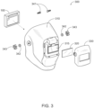
- FIG. 3 illustrates an exploded view of one embodiment of a welding helmet 300 that is configured to have the auto-darkening apparatus 100 of FIG. 1A, FIG. 1B, FIG. 1C , and FIG. 2 installed therein.
- the welding helmet 300 includes a shell 310, a viewing window 315 (e.g., an open viewing window), a spatter shield 320, a front bezel 330, and headgear mounting hardware 341, 342, 343 for a headgear (not shown).
- the spatter shield 320 and the front bezel 330 are installed from the front of the shell 310.
- the auto-darkening apparatus 100 is installed from the rear of the shell 310, similar to a conventional auto-darkening filter.
- the auto-darkening apparatus 100 has the integrated magnification assembly 180, providing a continuously adjustable magnification capability as described herein.
- U.S. Patent No. 9,889,045 discusses various examples of welding helmet configurations and is incorporated herein by reference.
- the magnification assembly 180 may be in a different housing from that of the auto-darkening elements.
- FIG. 4 illustrates an exploded view of one embodiment of an auto-darkening apparatus 400 for supporting welding performed by a human welder.
- the elements of the auto-darkening apparatus 400 are similar to those of the auto-darkening apparatus 100 of FIG. 2 , except that the auto-darkening apparatus 400 does not include the magnification assembly 180.
- FIG. 5 illustrates one embodiment of a magnifying apparatus 500 having the magnification assembly 180 integrated therein, for supporting welding performed by a human welder, which is housed in a separate housing 510 from that of the auto-darkening apparatus 400.
- FIG. 6A illustrates the relationship of the auto-darkening apparatus 400 of FIG. 4 with respect to the magnifying apparatus 500 of FIG. 5 .
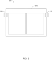
- FIG. 6B illustrates the magnifying apparatus 500 of FIG. 5 positioned directly behind and abutting the auto-darkening apparatus 400 of FIG. 4 as it would be when installed in a welding helmet.
- FIG. 7 illustrates an exploded view of one embodiment of a welding helmet 700 that is configured to have the auto-darkening apparatus 400 and the magnifying apparatus 500 of FIG. 6A and FIG. 6B installed therein.
- the welding helmet 700 is similar to the welding helmet 300 of FIG. 3 , except that the welding helmet 700 is configured for installation of the auto-darkening apparatus 400 and the magnifying apparatus 500, instead of the auto-darkening apparatus 100.
- the auto-darkening apparatus 400 is installed first, from the rear of the shell 310, followed by installation of the magnifying apparatus 500.
- the resultant darkening and magnification capabilities are essentially the same in both of the welding helmets 300 and 700.
- FIG. 8 illustrates a block diagram of an example embodiment of a controller 800 that can be used, for example, as the controller 130 in the auto-darkening apparatus 100 of FIG. 2 , or as the controller 130 in the auto-darkening apparatus 400 of FIG. 4 .
- the controller 800 includes at least one processor 814 (e.g., a microprocessor) which communicates with a number of other components via a bus subsystem 812.
- processor 814 e.g., a microprocessor
- These other devices may include a storage subsystem 824, including, for example, a memory subsystem 828 and a file storage subsystem 826, user interface input devices 822, user interface output devices 820, and a network interface subsystem 816.
- the input and output devices allow user interaction with the controller 800.
- Network interface subsystem 816 provides an interface to outside networks and is coupled to corresponding interface devices in yet other devices.
- User interface input devices 822 may include audio input devices such as voice recognition systems and microphones, or wireless communication devices (e.g., Bluetooth ® or Wi-Fi devices), for example.
- input device is intended to include all possible types of devices and ways to input information into the controller 800 from the user or onto a communication network, which fit within the form factor of an auto-darkening apparatus.
- User interface output devices 820 may include audio output devices such as speakers, or wireless communication devices (e.g., Bluetooth ® or Wi-Fi devices), for example.
- output device is intended to include all possible types of devices and ways to output information from the controller 800 to the user or to another machine or computer system, which fit within the form factor of an auto-darkening apparatus.
- Storage subsystem 824 stores programming and data constructs that provide some of the functionality described herein. For example, computer-executable instructions and data are generally executed by processor 814 alone or in combination with other processors.
- Memory 828 used in the storage subsystem 824 can include a number of memories including a main random access memory (RAM) 830 for storage of instructions and data during program execution and a read only memory (ROM) 832 in which fixed instructions are stored.
- a file storage subsystem 826 can provide persistent storage for program and data files and may include removable media such as a removable media cartridge, for example.
- the computer-executable instructions and data implementing the functionality of certain embodiments may be stored by file storage subsystem 826 in the storage subsystem 824, or in other machines accessible by the processor(s) 814 (e.g., via wireless communication means).
- Bus subsystem 812 provides a mechanism for letting the various components and subsystems of the controller 800 communicate with each other as intended. Although bus subsystem 812 is shown schematically as a single bus, alternative embodiments of the bus subsystem may use multiple buses.
- the controller 800 can be of varying types. Due to the ever-changing nature of computing devices and networks, the description of the controller 800 depicted in FIG. 8 is intended only as a specific example for purposes of illustrating some embodiments. Many other configurations of a controller are possible, having more or fewer components than the controller 800 depicted in FIG. 8 .
Landscapes
- Health & Medical Sciences (AREA)
- Physics & Mathematics (AREA)
- Engineering & Computer Science (AREA)
- Optics & Photonics (AREA)
- General Physics & Mathematics (AREA)
- Heart & Thoracic Surgery (AREA)
- Biomedical Technology (AREA)
- Animal Behavior & Ethology (AREA)
- General Health & Medical Sciences (AREA)
- Public Health (AREA)
- Veterinary Medicine (AREA)
- Vascular Medicine (AREA)
- Life Sciences & Earth Sciences (AREA)
- Ophthalmology & Optometry (AREA)
- Mechanical Engineering (AREA)
- General Engineering & Computer Science (AREA)
- Helmets And Other Head Coverings (AREA)
- Lenses (AREA)
- Laser Beam Processing (AREA)
Abstract
Description
- The disclosure of
U.S. Patent No. 5,825,441 , issued on October 20, 1998, is incorporated by reference herein in its entirety. The disclosure ofU.S. Patent No. 6,097,451, issued on August 1, 2000 , is incorporated by reference herein in its entirety. The disclosure ofU.S. Patent No. 7,477,330 B2, issued on January 13, 2009 , is incorporated by reference herein in its entirety. The disclosure ofU.S. Patent No. 9,889,045 B2, issued on February 1, 2018 - Embodiments of the present invention relate to automatic darkening filter assemblies for welding helmets. More specifically, embodiments of the present invention relate to automatic darkening filter assemblies for welding helmets having adjustable magnification capability.
- Welding magnifiers (cheater lenses) are commonly used in welding helmets over top of the welding lens for both passive and auto darkening helmets. Such clear magnifiers can be bothersome to change in and out based on various welding conditions, are easily scratched and, in older welders, can cause double vision from stacking three lenses (i.e., a clear cover plate, a welding lens, and a magnifying lens).
- An embodiment includes an automatic darkening filter (ADF) housing having an ADF lens and a mechanically adjustable magnifying lens integrated therein. Magnifying strength may range from 1.00 - 3.00 magnification, for example, and is continuously adjustable in accordance with one embodiment. A welder is able to adjust the desired level of magnification without the need for a separate lens (without having to swap out one lens for another). The welder is able to adjust the magnification level up or down based on their liking for each welding application and limitations of near and far sightedness (i.e., restrictions in how close or far the welder's eyes are from the welding arc, the size of the welding arc, and small or large weld puddles).
- One embodiment provides an auto-darkening apparatus for supporting welding performed by a human welder. The auto-darkening apparatus includes a housing configured to be removably installed into a welding helmet. The auto-darkening apparatus also includes an ADF lens assembly configured to transition from an un-darkened state to a darkened state in response to light from an arc being formed between a welding electrode and a work piece during a welding process. The auto-darkening apparatus further includes a magnification assembly integrated with the ADF lens assembly within the housing. The magnification assembly is configured to provide magnification of light coming through the ADF lens assembly. The magnification is continuously user-adjustable from a defined lower level of magnification to a defined upper level of magnification. In one embodiment, the defined lower level of magnification is a magnification level of 1 (i.e., no magnification). In one embodiment, the defined upper level of magnification is between 1.9 and 4.1. In one embodiment, the defined upper level of magnification is between 1.4 and 2.1. In one embodiment, the magnification assembly includes at least one optical magnifying lens. In one embodiment, the magnification assembly includes at least one convex optical lens. In one embodiment, the magnification assembly includes at least one concave optical lens. In one embodiment, the magnification assembly includes an optical lens configuration and a magnifying lens adjustment configured to be manipulated by a user to mechanically adjust an angle at which at least a portion of the optical lens configuration is oriented within the housing, resulting in an adjustment of a level of magnification of light coming through the ADF lens assembly as viewed by the user. In one embodiment, the magnification assembly includes an optical lens configuration and a magnifying lens adjustment configured to be manipulated by a user to mechanically adjust at least one of a focal length of the optical lens configuration or a position of at least a portion of the optical lens configuration within the housing, resulting in an adjustment of a level of magnification of light coming through the ADF lens assembly as viewed by the user. In one embodiment, the auto-darkening apparatus is configured to provide user adjustment of at least one of a sensitivity, a shade, and a delay of the ADF lens assembly.
- One embodiment provides a welding helmet for supporting welding performed by a human welder. The welding helmet includes a helmet shell, having a viewing window, configured to be worn on the head of a user. The welding helmet also includes an ADF lens assembly, within a first housing, configured to transition from an un-darkened state to a darkened state in response to light from an arc being formed between a welding electrode and a work piece during a welding process. The first housing is configured to be removably attached to the helmet shell at the viewing window. The welding helmet further includes a magnification assembly, within a second housing, configured to provide magnification of light coming through the ADF lens assembly. The magnification is continuously user-adjustable from a defined lower level of magnification to a defined upper level of magnification. The second housing is configured to be removably attached to the helmet shell adjacent to the first housing at the viewing window. In one embodiment, the defined lower level of magnification is a magnification level of 1 (i.e., no magnification). In one embodiment, the defined upper level of magnification is between 1.9 and 4.1. In one embodiment, the defined upper level of magnification is between 1.4 and 2.1. In one embodiment, the magnification assembly includes at least one optical magnifying lens. In one embodiment, the magnification assembly includes at least one convex optical lens. In one embodiment, the magnification assembly includes at least one concave optical lens. In one embodiment, the magnification assembly includes an optical lens configuration and a magnifying lens adjustment configured to be manipulated by a user to mechanically adjust an angle at which at least a portion of the optical lens configuration is oriented within the second housing, resulting in an adjustment of a level of magnification of light coming through the ADF lens assembly as viewed by the user. In one embodiment, the magnification assembly includes an optical lens configuration and a magnifying lens adjustment configured to be manipulated by a user to mechanically adjust at least one of focal length of the optical lens configuration or a position of at least a portion of the optical lens configuration within the second housing, resulting in an adjustment of a level of magnification of light coming through the ADF lens assembly as viewed by the user. In one embodiment, the welding helmet is configured to provide user adjustment of at least one of a sensitivity, a shade, and a delay of the ADF lens assembly.
- Numerous aspects of the general inventive concepts will become readily apparent from the following detailed description of exemplary embodiments, from the claims, and from the accompanying drawings.
- The accompanying drawings, which are incorporated in and constitute a part of the specification, illustrate various embodiments of the disclosure. It will be appreciated that the illustrated element boundaries (e.g., boxes, groups of boxes, or other shapes) in the figures represent one embodiment of boundaries. In some embodiments, one element may be designed as multiple elements or multiple elements may be designed as one element. In some embodiments, an element shown as an internal component of another element may be implemented as an external component and vice versa. Furthermore, elements may not be drawn to scale.
-
FIG. 1A, FIG. 1B, and FIG. 1C illustrates several views of one embodiment of an auto-darkening apparatus for supporting welding performed by a human welder; -
FIG. 2 illustrates an exploded view of the auto-darkening apparatus ofFIG. 1 ; -
FIG. 3 illustrates an exploded view of one embodiment of a welding helmet that is configured to have the auto-darkening apparatus ofFIG. 1A, FIG. 1B, FIG. 1C , andFIG. 2 installed therein; -
FIG. 4 illustrates an exploded view of one embodiment of an auto-darkening apparatus for supporting welding performed by a human welder; -
FIG. 5 illustrates one embodiment of a magnifying apparatus having a magnification assembly integrated therein, for supporting welding performed by a human welder, which is housed in a separate housing from that of the auto-darkening apparatus ofFIG. 4 ; -
FIG. 6A illustrates the relationship of the auto-darkening apparatus ofFIG. 4 with respect to the magnifying apparatus ofFIG. 5 ; -
FIG. 6B illustrates the magnifying apparatus ofFIG. 5 positioned directly behind and abutting the auto-darkening apparatus ofFIG. 4 as they would be when installed in a welding helmet; -
FIG. 7 illustrates an exploded view of one embodiment of a welding helmet that is configured to have the auto-darkening apparatus and the magnifying apparatus ofFIG. 6A installed therein; and -
FIG. 8 illustrates a block diagram of an example embodiment of a controller that can be used, for example, as the controller in the auto-darkening apparatus ofFIG. 2 , or as the controller in the auto-darkening apparatus ofFIG. 4 . - One embodiment of the present invention includes an auto-darkening apparatus having an ADF lens assembly integrated with a magnification assembly within an ADF housing for use in a welding helmet. One embodiment of the present invention includes a welding helmet configured to have installed therein an auto-darkening apparatus having an ADF lens assembly integrated with a magnification assembly within an ADF housing. In one embodiment, the auto-darkening apparatus is in the form of a cartridge that removably snaps into the welding helmet.
- The examples and figures herein are illustrative only and are not meant to limit the subj ect invention, which is measured by the scope and spirit of the claims. Referring now to the drawings, wherein the showings are for the purpose of illustrating exemplary embodiments of the subject invention only and not for the purpose of limiting same,
FIG. 1A, FIG. 1B, and FIG. 1C illustrates several views of one embodiment of an auto-darkeningapparatus 100 for supporting welding performed by a human welder. -
FIG. 1A is a rear view (as viewed by a user) of the auto-darkeningapparatus 100,FIG. 1B is a top view of the auto-darkeningapparatus 100, andFIG. 1C is a side view of the auto-darkeningapparatus 100. The form factor of the auto-darkeningapparatus 100 is defined primarily by a housing 120 (a.k.a. a cartridge-like housing 120), which houses the internal components of theapparatus 100. As shown inFIG. 1A, FIG. 1B, and FIG. 1C , the auto-darkeningapparatus 100 has asensitivity adjustment 102, ashade adjustment 104, and adelay adjustment 106. Such types of ADF lens adjustments are known in the art. The auto-darkeningapparatus 100 also has two magnifyinglens adjustments various adjustments -
FIG. 2 illustrates an exploded view of the auto-darkeningapparatus 100 ofFIG. 1 . In addition to theadjustments apparatus 100 also includes afront housing 122 and arear housing 124 which come together to form a single housing or cartridge 120 (e.g., seeFIG. 1B and FIG. 1C ). Integrated within thehousing 120 is acontroller 130, a liquid crystal display (LCD) stack 140 (a.k.a. an ADF lens assembly 140), aleft magnifying lens 150 and a right magnifying lens 160 (a.k.a. anoptical lens configuration 170 as delineated by a dotted oval inFIG. 2 ). The magnifyinglenses 150 and 160 (the optical lens configuration 170), along with the two magnifyinglens adjustments magnification assembly 180, as delineated by another dotted oval inFIG. 2 . The auto-darkeningapparatus 100 also includes abattery clip 190 for holding a battery used to power theapparatus 100. The ordering of the primary components of the auto-darkeningapparatus 100 are (from front to rear) thefront housing 122, thecontroller 130, theADF lens assembly 140, themagnification assembly 180, and therear housing 124. - The
controller 130 controls much of the functionality of the auto-darkeningapparatus 100 and may be implemented on a printed circuit board (PCB).FIG. 8 herein discusses one embodiment of acontroller 800 which may be used as thecontroller 130. Certain functionality controlled by thecontroller 130 includes switching of theADF lens assembly 140 between an un-darkened state and a darkened state (e.g., in response to light from an arc being formed or extinguished between a welding electrode and a work piece during a welding process) and the setting of the sensitivity, the shade, and the delay via thesensitivity adjustment 102, theshade adjustment 104, and thedelay adjustment 106 respectively, as selected by the user. TheADF lens assembly 140 may include various layers of LCD lenses and polarization filters, for example, as discussed inU.S. Patent No. 5,825,441 ,U.S. Patent No. 6,097,451 , andU.S. Patent No. 7,477,330 which are incorporated herein by reference. Thefront housing 122 and therear housing 124 are largely molded plastic components, in accordance with one embodiment. - The magnifying
lenses magnification assembly 180 are optical lenses (e.g., convex optical lenses of a thin lens design) made of glass, in accordance with one embodiment. In some other embodiments, the magnifyinglenses lenses - In the exploded configuration of
FIG. 2 , the magnifyinglenses ADF lens assembly 140. Each magnifyinglens magnification assembly 180 is configured to provide magnification of light coming through theADF lens assembly 140 such that the magnification is continuously user-adjustable from a defined lower level of magnification (e.g., 1X or no magnification) to a defined upper level of magnification (e.g., 2X, 3X, or 4X magnification). The level of magnification is mechanically adjustable, via the magnifyinglens adjustments - In one embodiment, the
magnification assembly 180 includes the optical lens configuration 170 (having magnifyinglenses 150 and 160) and the magnifyinglens adjustments lens adjustments respective lenses housing 120, resulting in an adjustment of a level of magnification with respect to light coming through theADF lens assembly 140. For example, in accordance with one embodiment, each of the magnifyinglenses - In accordance with one embodiment, each of the magnifying
lens adjustments lenses lens adjustments lenses lenses lens adjustments respective magnifying lenses lenses -
FIG. 3 illustrates an exploded view of one embodiment of awelding helmet 300 that is configured to have the auto-darkeningapparatus 100 ofFIG. 1A, FIG. 1B, FIG. 1C , andFIG. 2 installed therein. Thewelding helmet 300 includes ashell 310, a viewing window 315 (e.g., an open viewing window), aspatter shield 320, afront bezel 330, andheadgear mounting hardware spatter shield 320 and thefront bezel 330 are installed from the front of theshell 310. The auto-darkeningapparatus 100 is installed from the rear of theshell 310, similar to a conventional auto-darkening filter. However, unlike a conventional auto-darkening filter, the auto-darkeningapparatus 100 has the integratedmagnification assembly 180, providing a continuously adjustable magnification capability as described herein.U.S. Patent No. 9,889,045 - In other embodiments, the
magnification assembly 180 may be in a different housing from that of the auto-darkening elements. For example,FIG. 4 illustrates an exploded view of one embodiment of an auto-darkeningapparatus 400 for supporting welding performed by a human welder. The elements of the auto-darkeningapparatus 400 are similar to those of the auto-darkeningapparatus 100 ofFIG. 2 , except that the auto-darkeningapparatus 400 does not include themagnification assembly 180. Instead,FIG. 5 illustrates one embodiment of amagnifying apparatus 500 having themagnification assembly 180 integrated therein, for supporting welding performed by a human welder, which is housed in aseparate housing 510 from that of the auto-darkeningapparatus 400. Various embodiments of themagnifying apparatus 500 operate similarly to the various embodiments of themagnification assembly 180 discussed herein. The magnifyingapparatus 500 is a largely mechanical apparatus and does not require acontroller 130 or a battery, as does the auto-darkeningapparatus 400. As a resultFIG. 6A illustrates the relationship of the auto-darkeningapparatus 400 ofFIG. 4 with respect to themagnifying apparatus 500 ofFIG. 5 .FIG. 6B illustrates the magnifyingapparatus 500 ofFIG. 5 positioned directly behind and abutting the auto-darkeningapparatus 400 ofFIG. 4 as it would be when installed in a welding helmet. -
FIG. 7 illustrates an exploded view of one embodiment of awelding helmet 700 that is configured to have the auto-darkeningapparatus 400 and themagnifying apparatus 500 ofFIG. 6A and FIG. 6B installed therein. Thewelding helmet 700 is similar to thewelding helmet 300 ofFIG. 3 , except that thewelding helmet 700 is configured for installation of the auto-darkeningapparatus 400 and themagnifying apparatus 500, instead of the auto-darkeningapparatus 100. The auto-darkeningapparatus 400 is installed first, from the rear of theshell 310, followed by installation of themagnifying apparatus 500. However, the resultant darkening and magnification capabilities are essentially the same in both of thewelding helmets -
FIG. 8 illustrates a block diagram of an example embodiment of acontroller 800 that can be used, for example, as thecontroller 130 in the auto-darkeningapparatus 100 ofFIG. 2 , or as thecontroller 130 in the auto-darkeningapparatus 400 ofFIG. 4 . Referring toFIG. 8 , thecontroller 800 includes at least one processor 814 (e.g., a microprocessor) which communicates with a number of other components via abus subsystem 812. These other devices may include astorage subsystem 824, including, for example, amemory subsystem 828 and afile storage subsystem 826, user interface input devices 822, userinterface output devices 820, and anetwork interface subsystem 816. The input and output devices allow user interaction with thecontroller 800.Network interface subsystem 816 provides an interface to outside networks and is coupled to corresponding interface devices in yet other devices. - User interface input devices 822 may include audio input devices such as voice recognition systems and microphones, or wireless communication devices (e.g., Bluetooth® or Wi-Fi devices), for example. In general, use of the term "input device" is intended to include all possible types of devices and ways to input information into the
controller 800 from the user or onto a communication network, which fit within the form factor of an auto-darkening apparatus. Userinterface output devices 820 may include audio output devices such as speakers, or wireless communication devices (e.g., Bluetooth® or Wi-Fi devices), for example. In general, use of the term "output device" is intended to include all possible types of devices and ways to output information from thecontroller 800 to the user or to another machine or computer system, which fit within the form factor of an auto-darkening apparatus. -
Storage subsystem 824 stores programming and data constructs that provide some of the functionality described herein. For example, computer-executable instructions and data are generally executed byprocessor 814 alone or in combination with other processors.Memory 828 used in thestorage subsystem 824 can include a number of memories including a main random access memory (RAM) 830 for storage of instructions and data during program execution and a read only memory (ROM) 832 in which fixed instructions are stored. Afile storage subsystem 826 can provide persistent storage for program and data files and may include removable media such as a removable media cartridge, for example. The computer-executable instructions and data implementing the functionality of certain embodiments may be stored byfile storage subsystem 826 in thestorage subsystem 824, or in other machines accessible by the processor(s) 814 (e.g., via wireless communication means). -
Bus subsystem 812 provides a mechanism for letting the various components and subsystems of thecontroller 800 communicate with each other as intended. Althoughbus subsystem 812 is shown schematically as a single bus, alternative embodiments of the bus subsystem may use multiple buses. - The
controller 800 can be of varying types. Due to the ever-changing nature of computing devices and networks, the description of thecontroller 800 depicted inFIG. 8 is intended only as a specific example for purposes of illustrating some embodiments. Many other configurations of a controller are possible, having more or fewer components than thecontroller 800 depicted inFIG. 8 . - While the disclosed embodiments have been illustrated and described in considerable detail, it is not the intention to restrict or in any way limit the scope of any subsequent appended claims to such detail. It is, of course, not possible to describe every conceivable combination of components or methodologies for purposes of describing the various aspects of the subject matter. Therefore, the disclosure is not limited to the specific details or illustrative examples shown and described. Thus, this disclosure is intended to embrace alterations, modifications, and variations that fall within the scope of subsequent appended claims, which satisfy the statutory subject matter requirements of 35 U.S.C. §101. The above description of specific embodiments has been given by way of example. From the disclosure given, those skilled in the art will not only understand the general inventive concepts and attendant advantages, but will also find apparent various changes and modifications to the structures and methods disclosed. It is sought, therefore, to cover all such changes and modifications as fall within the spirit and scope of the general inventive concepts, as defined by subsequent appended claims, and equivalents thereof.
Claims (15)
- An auto-darkening apparatus for supporting welding performed by a human welder, the auto-darkening apparatus comprising:a housing configured to be removably installed into a welding helmet;an ADF lens assembly configured to transition from an un-darkened state to a darkened state in response to light from an arc being formed between a welding electrode and a work piece during a welding process; anda magnification assembly integrated with the ADF lens assembly within the housing,wherein the magnification assembly is configured to provide magnification of light coming through the ADF lens assembly, and wherein the magnification is continuously user-adjustable from a defined lower level of magnification to a defined upper level of magnification.
- The apparatus of claim 1, wherein the defined lower level of magnification is a magnification level of 1 or no magnification.
- The apparatus of claim 1, wherein the defined upper level of magnification is between 1.9 and 4.1, preferably between 1.4 and 2.1.
- The apparatus of claim 1, wherein the magnification assembly includes at least one optical magnifying lens.
- The apparatus of claim 1, wherein the magnification assembly includes at least one concave optical lens or at least one convex optical lens.
- The apparatus of claim 1, wherein the magnification assembly includes an optical lens configuration and a magnifying lens adjustment configured to be manipulated by a user to mechanically adjust an angle at which at least a portion of the optical lens configuration is oriented within the housing, resulting in an adjustment of a level of magnification of light coming through the ADF lens assembly as viewed by the user.
- The apparatus of claim 1, wherein the magnification assembly includes an optical lens configuration and a magnifying lens adjustment configured to be manipulated by a user to mechanically adjust at least one of a focal length of the optical lens configuration or a position of at least a portion of the optical lens configuration within the housing, resulting in an adjustment of a level of magnification of light coming through the ADF lens assembly as viewed by the user.
- The apparatus of claim 1, wherein the auto-darkening apparatus is configured to provide user adjustment of at least one of a sensitivity, a shade, and a delay of the ADF lens assembly.
- A welding helmet for supporting welding performed by a human welder, the welding helmet comprising:a helmet shell, having a viewing window, configured to be worn on the head of a user;an ADF lens assembly within a first housing, the ADF lens assembly configured to transition from an un-darkened state to a darkened state in response to light from an arc being formed between a welding electrode and a work piece during a welding process, wherein the first housing is configured to be removably attached to the helmet shell at the viewing window; anda magnification assembly within a second housing, the magnification assembly configured to provide magnification of light coming through the ADF lens assembly, wherein the magnification is continuously user-adjustable from a defined lower level of magnification to a defined upper level of magnification, and wherein the second housing is configured to be removably attached to the helmet shell adjacent to the first housing at the viewing window.
- The welding helmet of claim 9, wherein the defined lower level of magnification is a magnification level of 1 or no magnification and the defined upper level of magnification is between 1.9 and 4.1, preferably between 1.4 and 2.1.
- The welding helmet of claim 9, wherein the magnification assembly includes at least one optical magnifying lens.
- The welding helmet of claim 9, wherein the magnification assembly includes at least one concave optical lens or at least one convex optical lens.
- The welding helmet of claim 9, wherein the magnification assembly includes an optical lens configuration and a magnifying lens adjustment configured to be manipulated by a user to mechanically adjust an angle at which at least a portion of the optical lens configuration is oriented within the second housing, resulting in an adjustment of a level of magnification of light coming through the ADF lens assembly as viewed by the user.
- The welding helmet of claim 9, wherein the magnification assembly includes an optical lens configuration and a magnifying lens adjustment configured to be manipulated by a user to mechanically adjust at least one of focal length of the optical lens configuration or a position of at least a portion of the optical lens configuration within the second housing, resulting in an adjustment of a level of magnification of light coming through the ADF lens assembly as viewed by the user.
- The welding helmet of claim 9, wherein the welding helmet is configured to provide user adjustment of at least one of a sensitivity, a shade, and a delay of the ADF lens assembly.
Applications Claiming Priority (1)
| Application Number | Priority Date | Filing Date | Title |
|---|---|---|---|
| US17/859,134 US12605284B2 (en) | 2022-07-07 | 2022-07-07 | Automatic darkening apparatus with integrated magnification lens |
Publications (3)
| Publication Number | Publication Date |
|---|---|
| EP4306088A1 true EP4306088A1 (en) | 2024-01-17 |
| EP4306088C0 EP4306088C0 (en) | 2026-04-08 |
| EP4306088B1 EP4306088B1 (en) | 2026-04-08 |
Family
ID=86942420
Family Applications (1)
| Application Number | Title | Priority Date | Filing Date |
|---|---|---|---|
| EP23180625.8A Active EP4306088B1 (en) | 2022-07-07 | 2023-06-21 | Automatic darkening apparatus with integrated magnification lens |
Country Status (5)
| Country | Link |
|---|---|
| US (1) | US12605284B2 (en) |
| EP (1) | EP4306088B1 (en) |
| JP (1) | JP2024008870A (en) |
| KR (1) | KR102969393B1 (en) |
| CN (1) | CN117369111A (en) |
Families Citing this family (2)
| Publication number | Priority date | Publication date | Assignee | Title |
|---|---|---|---|---|
| US12090089B2 (en) * | 2016-11-16 | 2024-09-17 | Illinois Tool Works Inc. | Lighting attachment for welding helmets |
| KR20260066756A (en) * | 2024-04-07 | 2026-05-12 | 타이커만 일렉트로닉스 코., 엘티디 | Automatic light-blocking laser light filter and welding helmet |
Citations (7)
| Publication number | Priority date | Publication date | Assignee | Title |
|---|---|---|---|---|
| US5825441A (en) | 1994-04-26 | 1998-10-20 | Hoernell; Ake | Liquid crystal welding glass shields having improved optical angular properties |
| US6097451A (en) | 1995-10-26 | 2000-08-01 | Hornell International Ab | Liquid crystal shutter with low twisted nematic liquid crystal cells driven with a low frequency or DC voltage |
| US20070089215A1 (en) * | 2005-10-26 | 2007-04-26 | Lightswitch Safety Systems, Inc. | Bifocal magnifier plate for use in welding |
| US7477330B2 (en) | 2005-03-09 | 2009-01-13 | 3M Innovative Properties Company | Automatic darkening filter with offset polarizers |
| US9889045B2 (en) | 2006-08-23 | 2018-02-13 | Lincoln Global, Inc. | User-friendly welding helmet assembly |
| US20190125586A1 (en) * | 2016-04-27 | 2019-05-02 | 3M Innovative Properties Company | Welding Protector With Magnifying Cover |
| WO2021149942A1 (en) * | 2020-01-22 | 2021-07-29 | 주식회사 오토스윙 | Welding information providing apparatus |
Family Cites Families (14)
| Publication number | Priority date | Publication date | Assignee | Title |
|---|---|---|---|---|
| US2230369A (en) * | 1938-03-30 | 1941-02-04 | Henry W Wise | Lens for goggles |
| CN87216198U (en) | 1987-12-04 | 1988-09-14 | 诸声商 | Welding face mask with magnifying glass |
| JPH07318850A (en) * | 1994-05-23 | 1995-12-08 | Olympus Optical Co Ltd | Head-mounted video display |
| JPH10234771A (en) * | 1997-02-24 | 1998-09-08 | Higoguriraa Kk | Protective surface for welding |
| FR2775894B1 (en) | 1998-03-12 | 2000-06-23 | Soudure Autogene Francaise | INFRARED VISION WELDING HELMET |
| US20060010551A1 (en) | 2004-07-14 | 2006-01-19 | Bishop Timothy D | Welding face covering |
| US9271871B2 (en) * | 2009-11-23 | 2016-03-01 | Jerry Dean Wright | Face protector lens assembly and method of use |
| US8438663B2 (en) | 2009-11-23 | 2013-05-14 | Jerry Dean Wright | Face protector lens assembly and method of use |
| US20110285957A1 (en) | 2010-05-24 | 2011-11-24 | William Mikulenka | Limited access and antifog protective eyewear for welding |
| US9073138B2 (en) | 2011-05-16 | 2015-07-07 | Lincoln Global, Inc. | Dual-spectrum digital imaging welding helmet |
| US20150320601A1 (en) | 2014-05-07 | 2015-11-12 | Prism Technologies Llc | Method and system for mediated reality welding |
| US11033433B2 (en) * | 2014-06-16 | 2021-06-15 | Illinois Tool Works Inc | Removable shield for protective headwear |
| US20200114456A1 (en) * | 2018-10-10 | 2020-04-16 | Lincoln Global, Inc. | Systems and methods including a head-mounted device for use in arc welding |
| IT202000013351A1 (en) | 2020-06-05 | 2021-12-05 | Eps Systems Srl | VOLTAIC ARC EQUIPMENT AND WORKING METHOD |
-
2022
- 2022-07-07 US US17/859,134 patent/US12605284B2/en active Active
-
2023
- 2023-06-21 EP EP23180625.8A patent/EP4306088B1/en active Active
- 2023-06-28 CN CN202310772917.2A patent/CN117369111A/en active Pending
- 2023-06-29 KR KR1020230083985A patent/KR102969393B1/en active Active
- 2023-06-29 JP JP2023107084A patent/JP2024008870A/en active Pending
Patent Citations (7)
| Publication number | Priority date | Publication date | Assignee | Title |
|---|---|---|---|---|
| US5825441A (en) | 1994-04-26 | 1998-10-20 | Hoernell; Ake | Liquid crystal welding glass shields having improved optical angular properties |
| US6097451A (en) | 1995-10-26 | 2000-08-01 | Hornell International Ab | Liquid crystal shutter with low twisted nematic liquid crystal cells driven with a low frequency or DC voltage |
| US7477330B2 (en) | 2005-03-09 | 2009-01-13 | 3M Innovative Properties Company | Automatic darkening filter with offset polarizers |
| US20070089215A1 (en) * | 2005-10-26 | 2007-04-26 | Lightswitch Safety Systems, Inc. | Bifocal magnifier plate for use in welding |
| US9889045B2 (en) | 2006-08-23 | 2018-02-13 | Lincoln Global, Inc. | User-friendly welding helmet assembly |
| US20190125586A1 (en) * | 2016-04-27 | 2019-05-02 | 3M Innovative Properties Company | Welding Protector With Magnifying Cover |
| WO2021149942A1 (en) * | 2020-01-22 | 2021-07-29 | 주식회사 오토스윙 | Welding information providing apparatus |
Also Published As
| Publication number | Publication date |
|---|---|
| KR102969393B1 (en) | 2026-05-26 |
| EP4306088C0 (en) | 2026-04-08 |
| KR20240007069A (en) | 2024-01-16 |
| US20240009034A1 (en) | 2024-01-11 |
| JP2024008870A (en) | 2024-01-19 |
| US12605284B2 (en) | 2026-04-21 |
| EP4306088B1 (en) | 2026-04-08 |
| CN117369111A (en) | 2024-01-09 |
Similar Documents
| Publication | Publication Date | Title |
|---|---|---|
| US5371556A (en) | Spectacle type retina direct display apparatus | |
| US6977776B2 (en) | Head-mounted optical direct visualization system | |
| EP4306088B1 (en) | Automatic darkening apparatus with integrated magnification lens | |
| CN100365470C (en) | Binocular optical device, in particular electronic spectacles, with an electronic camera for automatic sharpness adjustment, including correction of various vision errors | |
| US7992996B2 (en) | Spectacles-type image display device | |
| JP2896606B2 (en) | Image display device | |
| JP2006209138A (en) | Head-mounted display system with aspheric optics | |
| JP2007094422A (en) | Head mounted display system | |
| EP1798589A1 (en) | Image display unit and electronic glasses | |
| US20050057439A1 (en) | Cap with display device | |
| JPH07325266A (en) | Video display | |
| JPH08160344A (en) | Head mounted video display | |
| CN111328380A (en) | Head-mounted display and design method of wide-focus lens used in head-mounted display | |
| JP2010232718A (en) | Head-mounted image display apparatus | |
| JP2013044896A (en) | Head-mounted display | |
| CN105700140A (en) | Immersive video system with adjustable pupil distance | |
| JP2017134399A (en) | Glasses-free 3d display device without requiring interpupillary distance adjustment | |
| FI128248B (en) | Eyepiece for a personal display and personal display comprising such eyepiece | |
| JPH0772420A (en) | Image display device | |
| JPH06141258A (en) | Eyeglass type image display device | |
| WO2002084370A1 (en) | Visual aid | |
| JP2000284184A (en) | Parallel stereo microscope and objective lens | |
| JP3163701B2 (en) | Glasses-type image display device | |
| JPH07140416A (en) | Head mounted display | |
| JPH06326945A (en) | Head-mounted type video display device |
Legal Events
| Date | Code | Title | Description |
|---|---|---|---|
| PUAI | Public reference made under article 153(3) epc to a published international application that has entered the european phase |
Free format text: ORIGINAL CODE: 0009012 |
|
| STAA | Information on the status of an ep patent application or granted ep patent |
Free format text: STATUS: THE APPLICATION HAS BEEN PUBLISHED |
|
| AK | Designated contracting states |
Kind code of ref document: A1 Designated state(s): AL AT BE BG CH CY CZ DE DK EE ES FI FR GB GR HR HU IE IS IT LI LT LU LV MC ME MK MT NL NO PL PT RO RS SE SI SK SM TR |
|
| STAA | Information on the status of an ep patent application or granted ep patent |
Free format text: STATUS: REQUEST FOR EXAMINATION WAS MADE |
|
| 17P | Request for examination filed |
Effective date: 20240701 |
|
| RBV | Designated contracting states (corrected) |
Designated state(s): AL AT BE BG CH CY CZ DE DK EE ES FI FR GB GR HR HU IE IS IT LI LT LU LV MC ME MK MT NL NO PL PT RO RS SE SI SK SM TR |
|
| RAP3 | Party data changed (applicant data changed or rights of an application transferred) |
Owner name: LINCOLN GLOBAL, INC. |
|
| STAA | Information on the status of an ep patent application or granted ep patent |
Free format text: STATUS: EXAMINATION IS IN PROGRESS |
|
| 17Q | First examination report despatched |
Effective date: 20250519 |
|
| GRAP | Despatch of communication of intention to grant a patent |
Free format text: ORIGINAL CODE: EPIDOSNIGR1 |
|
| STAA | Information on the status of an ep patent application or granted ep patent |
Free format text: STATUS: GRANT OF PATENT IS INTENDED |
|
| INTG | Intention to grant announced |
Effective date: 20251028 |
|
| GRAS | Grant fee paid |
Free format text: ORIGINAL CODE: EPIDOSNIGR3 |
|
| GRAA | (expected) grant |
Free format text: ORIGINAL CODE: 0009210 |
|
| STAA | Information on the status of an ep patent application or granted ep patent |
Free format text: STATUS: THE PATENT HAS BEEN GRANTED |
|
| AK | Designated contracting states |
Kind code of ref document: B1 Designated state(s): AL AT BE BG CH CY CZ DE DK EE ES FI FR GB GR HR HU IE IS IT LI LT LU LV MC ME MK MT NL NO PL PT RO RS SE SI SK SM TR |
|
| REG | Reference to a national code |
Ref country code: CH Ref legal event code: F10 Free format text: ST27 STATUS EVENT CODE: U-0-0-F10-F00 (AS PROVIDED BY THE NATIONAL OFFICE) Effective date: 20260408 Ref country code: GB Ref legal event code: FG4D |
|
| REG | Reference to a national code |
Ref country code: DE Ref legal event code: R096 Ref document number: 602023014739 Country of ref document: DE |
|
| REG | Reference to a national code |
Ref country code: IE Ref legal event code: FG4D |
|
| REG | Reference to a national code |
Ref country code: CH Ref legal event code: R17 Free format text: ST27 STATUS EVENT CODE: U-0-0-R10-R17 (AS PROVIDED BY THE NATIONAL OFFICE) Effective date: 20260527 |
|
| U01 | Request for unitary effect filed |
Effective date: 20260501 |
|
| U07 | Unitary effect registered |
Designated state(s): AT BE BG DE DK EE FI FR IT LT LU LV MT NL PT RO SE SI Effective date: 20260511 |
|
| REG | Reference to a national code |
Ref country code: CH Ref legal event code: U11 Free format text: ST27 STATUS EVENT CODE: U-0-0-U10-U11 (AS PROVIDED BY THE NATIONAL OFFICE) Effective date: 20260701 |