EP4305953A1 - Forage harvester - Google Patents
Forage harvester Download PDFInfo
- Publication number
- EP4305953A1 EP4305953A1 EP23179991.7A EP23179991A EP4305953A1 EP 4305953 A1 EP4305953 A1 EP 4305953A1 EP 23179991 A EP23179991 A EP 23179991A EP 4305953 A1 EP4305953 A1 EP 4305953A1
- Authority
- EP
- European Patent Office
- Prior art keywords
- cracker
- secondary frame
- frame
- right hand
- forage harvester
- Prior art date
- Legal status (The legal status is an assumption and is not a legal conclusion. Google has not performed a legal analysis and makes no representation as to the accuracy of the status listed.)
- Granted
Links
Images




Classifications
-
- A—HUMAN NECESSITIES
- A01—AGRICULTURE; FORESTRY; ANIMAL HUSBANDRY; HUNTING; TRAPPING; FISHING
- A01D—HARVESTING; MOWING
- A01D43/00—Mowers combined with apparatus performing additional operations while mowing
- A01D43/08—Mowers combined with apparatus performing additional operations while mowing with means for cutting up the mown crop, e.g. forage harvesters
-
- A—HUMAN NECESSITIES
- A01—AGRICULTURE; FORESTRY; ANIMAL HUSBANDRY; HUNTING; TRAPPING; FISHING
- A01F—PROCESSING OF HARVESTED PRODUCE; HAY OR STRAW PRESSES; DEVICES FOR STORING AGRICULTURAL OR HORTICULTURAL PRODUCE
- A01F12/00—Parts or details of threshing apparatus
- A01F12/18—Threshing devices
- A01F12/28—Devices for adjusting the concaves
-
- A—HUMAN NECESSITIES
- A01—AGRICULTURE; FORESTRY; ANIMAL HUSBANDRY; HUNTING; TRAPPING; FISHING
- A01D—HARVESTING; MOWING
- A01D43/00—Mowers combined with apparatus performing additional operations while mowing
- A01D43/10—Mowers combined with apparatus performing additional operations while mowing with means for crushing or bruising the mown crop
-
- A—HUMAN NECESSITIES
- A01—AGRICULTURE; FORESTRY; ANIMAL HUSBANDRY; HUNTING; TRAPPING; FISHING
- A01D—HARVESTING; MOWING
- A01D43/00—Mowers combined with apparatus performing additional operations while mowing
- A01D43/10—Mowers combined with apparatus performing additional operations while mowing with means for crushing or bruising the mown crop
- A01D43/105—Driving mechanisms
-
- A—HUMAN NECESSITIES
- A01—AGRICULTURE; FORESTRY; ANIMAL HUSBANDRY; HUNTING; TRAPPING; FISHING
- A01D—HARVESTING; MOWING
- A01D43/00—Mowers combined with apparatus performing additional operations while mowing
- A01D43/10—Mowers combined with apparatus performing additional operations while mowing with means for crushing or bruising the mown crop
- A01D43/107—Mounting means
-
- A—HUMAN NECESSITIES
- A01—AGRICULTURE; FORESTRY; ANIMAL HUSBANDRY; HUNTING; TRAPPING; FISHING
- A01F—PROCESSING OF HARVESTED PRODUCE; HAY OR STRAW PRESSES; DEVICES FOR STORING AGRICULTURAL OR HORTICULTURAL PRODUCE
- A01F15/00—Baling presses for straw, hay or the like
- A01F15/04—Plunger presses
Definitions
- the present invention relates to an improved forage harvester, and, in particular, to a cracker unit for a forage harvester.
- the cracker unit includes opposing cracker rollers through which harvested crop is fed.
- the harvested crop is first fed though a chopper unit and then into the cracker unit where it is squeezed and crushed between the opposing cracker rollers before being fed to a discharge spout.
- the cracker unit includes a first cracker roller, that is free to rotate, and can be driven about its longitudinal axis and is supported in bearings on a first frame element.
- the first cracker roller is located toward a first end of the cracker unit.
- a second cracker roller is provided.
- the second cracker roller is driven and supported in bearings on a second frame element.
- the second frame element is located to a second end of the cracker unit and can be linearly adjusted with respect to the first frame in order to adjust a spacing between the first and second cracker rollers.
- the first and second cracker rollers provide an elongate opening between left and right hand sides of the cracker unit through which harvested crop that is to be processed can be conveyed.
- the first frame element serves as a base of the cracker unit. Additional first and second covering elements are secured to the first frame element to form an upper housing of the cracker unit through which processed crop is directed towards the discharge spout.
- a pre-loading arrangement is provided on the second frame element such that the second cracker roller is preloaded towards the first cracker roller. Further, the spacing between the cracker rollers is adjustable by means of a linear adjustment apparatus in which the second frame element sits on a slide to adjust the position of the axis of rotation of the moveable second cracker roller with respect to that of the first cracker roller.
- the present invention provides an alternate mounting arrangement that enables adjustment of the moveable cracker roller with respect to its fixed counterpart. Other advantages of the present invention will be apparent from the description below.
- a forage harvester cracker unit comprises a base frame comprising left and right hand side elements, a first cracker roller being mounted on the base frame to be rotatable about a fixed central axis extending between the left and right hand side elements of the base frame and a secondary frame comprising left and right hand side elements, a second cracker roller being mounted on the secondary frame to be rotatable about a central axis extending between the left and right hand side elements of the secondary frame, wherein the forage harvester cracker unit further comprises a pivot axis extending through the base frame and the secondary frame, the secondary frame being adjustable about the pivot axis to enable variation of a separation of the first and second cracker rollers, a biasing element acting between the base frame and the secondary frame to urge the second cracker roller towards the first cracker roller and a drive element acting against the biasing element to hold the secondary frame in position against the biasing element to maintain a minimum separation of the first and second cracker rollers characterised in that character
- the biasing arrangement comprises parallel spring elements mounted on the base frame.
- the spring elements act to pull the secondary frame towards the base frame. Even more preferably, the spring elements are mounted adjacent the first cracker roller.
- the spring elements act to push the secondary frame towards the base frame. More preferably, the spring elements are mounted adjacent the second cracker roller.
- the drive arrangement further comprises an actuator to control rotation of the drive shaft.
- each of the left and right hand side elements of the secondary frame are provided with recessed portions to receive the distal end of each lever.
- each lever is provided with a pin to be received within the recessed portions of each of the left and right hand side elements of the secondary frame.
- Figure 1 shows a forage harvester provided with a front attachment 2 such as a header which contains cutting equipment for cutting and harvesting a crop.
- a front attachment 2 such as a header which contains cutting equipment for cutting and harvesting a crop.
- the cut crop is fed through a series of compression rolls 3a in a compression roller housing 3 to a chopper drum 4 where the crop is chopped into smaller pieces.
- the chopped crop passes through a duct 5 and is optionally directed into a cracker unit 6 where the crop is further crushed and threshed.
- the harvested crop is then blown upwards along a duct 5 by an accelerator 8 and exits through a spout 9.
- FIGS 2 and 3 show perspective views of a first embodiment of a cracker unit 6 for use in a forage harvester.
- a base frame 10 of the cracker unit 6 comprises first and second side panels 12,14 and connecting elements 16 extending between the first and second side panels 12,14.
- Each side panel 12,14 is provided with a outwardly extending lower flange 18, 20 and a post 22,24 secured to the side panel 12,16 and its lower flange 18,20 by any suitable means, for example by welding of the post 22,24 to the side panel 12,14.
- the posts 22,24 are arranged parallel to one another and each post 22,24 conveniently extends at an angle to the adjacent lower flange 18,20. In use the lower flanges are used to secure the cracker unit in position on a frame of the forage harvester 2.
- first mounting blocks 26,28 are secured to a first side of each of the posts 22,24.
- the first mounting blocks 26,28 each house a suitable bearing for supporting first and second ends of a first cracker roller 30.
- roller bearings are provided.
- the first mounting blocks 26,28 may be secured to the posts in any suitable manner, for example by bolts 34 (see FIG 5 ).
- the secondary frame comprises first and second end elements 42,44 each of generally triangular form.
- each of the first and second end elements 42,44 of the secondary frame is located adjacent to a respective side wall 12,14 and is located within a width defined by outer edges of the side flanges 18,20.
- Each of the first and second end elements 42,44 incorporate corresponding second mounting blocks 46,48.
- the second mounting blocks 46,48 each house a suitable bearing for supporting first and second ends of a second cracker roller 32. In the illustrated embodiment, roller bearings are provided.
- the first and second end elements 42,44 of the secondary frame are also connected by an axle 50 extending through a lower end of each of the first and second end elements 42,44.
- the axle 50 extends though suitable openings in the first and second side walls 12,14 of the base frame 10.
- the axle 50 allows the secondary frame to pivot with respect to the base frame 10 about a central axis of the axle 50.
- each first and second end element 42,44 adjacent a post 22,24 is provided with a mounting point.
- a biasing arrangement 58 is secured to the mounting point.
- the biasing arrangement 58 comprises a central elongate shank member 60 provided at a first end with a threaded head and at a second end with an opening.
- the second end of the elongate shank member 60 is secured to the mounting point by a pivot pin 62.
- a shank of the elongate member passes through an opening provided in the upper ends of each of the posts 22,24.
- the threaded head is conveniently provided with by first and second nuts 64,66.
- each spring element 72 is under compression and so will seek to draw the respective first and second end elements 42,44 of the secondary frame towards the corresponding post 22,24, that will (with reference to Figures 2 to 6 ) cause the secondary frame to rotate clockwise about the axle 50.
- each of the first and second end elements 42,44 of the secondary frame spaced from the posts 22,24 is provided with a recessed portion 80.
- the base frame 10 is provided at a second end with corresponding openings in the first and second side panels 12,14.
- a drive shaft 82 extends through the openings. Ends of the drive shaft 82 serve as mountings for corresponding pivot levers 84 provided to each side of the cracker unit 6. Lower ends of each pivot lever are mounted on an eccentric bearing.
- each pivot lever 84 The upper ends of each pivot lever 84 are provided with pins 86 adapted to be seated within the recessed portions 80 of the corresponding first and second end elements 42,44. As may be seen from Figure 5 , the pins 86 are conveniently retained by threaded elements 88 secured within a threaded recess of a main part of each pivot lever 84.
- One end of the drive shaft 82 is connected to a drive 90 (see Figure 7 ) such that longitudinal movement of a first shaft 92 causes the drive shaft 82 to be rotated. This in turn causes the pins 86 to pull down on the recessed portions 80 of the corresponding first and second end elements 42,44 of the secondary frame and so rotate the secondary frame about the axle 50 and away from the adjacent posts 22,24.
- the drive 90 may be actuated in any convenient manner.
- separation of the first and second cracker rollers 30,32 can be controlled by operation of the drive 90 by an operator (for example by the operator entering a desired separation into a user interface located within a cab of the forage harvester 2 and an electronic control unit operating the drive to deliver the desired separation.
- the biasing element allows temporary widening of the gap between the first and second cracker rollers 30,32 to prevent overloading of the bearings in the event of an excessive flow of harvested crop or of the passage of a foreign object between the first and second cracker rollers 30,32.
- the secondary frame again comprise first and second end elements 142 incorporating corresponding second mounting blocks 146.
- the first and second end elements of the secondary frame are again connected by an axle 150 extending through a lower end of each of the first and second end elements.
- the axle 150 extends though suitable openings in the first and second side walls of the base frame.
- the axle 150 allows the first and second end elements of the secondary frame to pivot with respect to the base frame 110 about a central axis of the axle 150.
- an upper end of each of the first and second end elements of the secondary frame spaced from the posts is provided with a recessed portion 180 to be engaged by a suitable pin 186 on the associated pivot lever 184.
- the pivot levers 184 to each side of the cracker unit are mounted on shaft 182 and are provided with a drive as in the first embodiment.
- the secondary housing is not provided with a biasing element acting between the secondary frame elements and the adjacent posts. Instead, a biasing arrangement 158 is arranged to each side of the cracker unit extending between the lower flange 118 and the secondary frame elements 142 mounted above the lower flanges 118.
- separation of the first and second cracker rollers 30,32 can be controlled by operation of the shaft 182 and the biasing arrangement 158 allows temporary widening of the gap between the first and second cracker rollers as required during operation of the cracker unit.
Landscapes
- Life Sciences & Earth Sciences (AREA)
- Environmental Sciences (AREA)
- Harvesting Machines For Specific Crops (AREA)
- Filling Or Emptying Of Bunkers, Hoppers, And Tanks (AREA)
Abstract
Description
- Not applicable.
- The present invention relates to an improved forage harvester, and, in particular, to a cracker unit for a forage harvester.
- It is known to provide forage harvesters with a cracker unit. The cracker unit includes opposing cracker rollers through which harvested crop is fed. The harvested crop is first fed though a chopper unit and then into the cracker unit where it is squeezed and crushed between the opposing cracker rollers before being fed to a discharge spout.
- The cracker unit includes a first cracker roller, that is free to rotate, and can be driven about its longitudinal axis and is supported in bearings on a first frame element. The first cracker roller is located toward a first end of the cracker unit. A second cracker roller is provided. In a known construction, the second cracker roller is driven and supported in bearings on a second frame element. The second frame element is located to a second end of the cracker unit and can be linearly adjusted with respect to the first frame in order to adjust a spacing between the first and second cracker rollers. Together the first and second cracker rollers provide an elongate opening between left and right hand sides of the cracker unit through which harvested crop that is to be processed can be conveyed. The first frame element serves as a base of the cracker unit. Additional first and second covering elements are secured to the first frame element to form an upper housing of the cracker unit through which processed crop is directed towards the discharge spout.
- A pre-loading arrangement is provided on the second frame element such that the second cracker roller is preloaded towards the first cracker roller. Further, the spacing between the cracker rollers is adjustable by means of a linear adjustment apparatus in which the second frame element sits on a slide to adjust the position of the axis of rotation of the moveable second cracker roller with respect to that of the first cracker roller.
- The present invention provides an alternate mounting arrangement that enables adjustment of the moveable cracker roller with respect to its fixed counterpart. Other advantages of the present invention will be apparent from the description below.
- According to a first aspect of the present invention, a forage harvester cracker unit comprises a base frame comprising left and right hand side elements, a first cracker roller being mounted on the base frame to be rotatable about a fixed central axis extending between the left and right hand side elements of the base frame and a secondary frame comprising left and right hand side elements, a second cracker roller being mounted on the secondary frame to be rotatable about a central axis extending between the left and right hand side elements of the secondary frame, wherein the forage harvester cracker unit further comprises a pivot axis extending through the base frame and the secondary frame, the secondary frame being adjustable about the pivot axis to enable variation of a separation of the first and second cracker rollers, a biasing element acting between the base frame and the secondary frame to urge the second cracker roller towards the first cracker roller and a drive element acting against the biasing element to hold the secondary frame in position against the biasing element to maintain a minimum separation of the first and second cracker rollers characterised in that characterised in that the drive arrangement comprises includes a drive shaft supported for rotation in bearings provided in the left and right hand side elements of the base frame, parallel levers eccentrically mounted on the left and right hand sides of the drive shaft, a distal end of each lever being retained within respective left and right hand side elements of the secondary frame so that rotation of the drive shaft about its axis results in movement of the secondary frame with respect to the base frame and the distance between the rolls to be varied.
- Preferably, the biasing arrangement comprises parallel spring elements mounted on the base frame.
- More preferably the spring elements act to pull the secondary frame towards the base frame. Even more preferably, the spring elements are mounted adjacent the first cracker roller.
- Alternatively, the spring elements act to push the secondary frame towards the base frame. More preferably, the spring elements are mounted adjacent the second cracker roller.
- Preferably, the drive arrangement further comprises an actuator to control rotation of the drive shaft.
- Preferably, each of the left and right hand side elements of the secondary frame are provided with recessed portions to receive the distal end of each lever.
- More preferably the distal end of each lever is provided with a pin to be received within the recessed portions of each of the left and right hand side elements of the secondary frame.
- Within the scope of this application, it should be understood that the various aspects, embodiments, examples and alternatives set out herein, and individual features thereof may be taken independently or in any possible and compatible combination. Where features are described with reference to a single aspect or embodiment, it should be understood that such features are applicable to all aspects and embodiments unless otherwise stated or where such features are incompatible.
- The invention will now be described, by way of example only, with reference to the accompanying drawings, in which:
-
FIG 1 shows a schematic side view of a forage harvester; -
FIG 2 shows a perspective view of a first embodiment of a cracker unit according to the present invention for use with a forage harvester; -
FIG 3 shows a perspective view of a cracker unit for use with a forage harvester similar to that ofFIG 2 in which elements of the cracker unit have been omitted; -
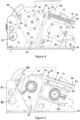
FIG 4 shows a first side view of the cracker unit ofFIG 3 showing elements of a cracker unit in accordance with the present invention; -
FIG 5 shows a sectional view of the elements shown inFIG 4 ; -
FIG 6 shows a detailed view of elements shown inFIG 4 ; -
FIG 7 shows an opposite side view of the forage harvester cracker unit in accordance with the present invention to that shown inFIG 4 ; and -
FIG 8 shows a side view of a second embodiment of a cracker unit according to the present invention for use with a forage harvester. - The invention will now be described in the following detailed description with reference to the drawings, wherein preferred embodiments are described in detail to enable practice of the invention. Although the invention is described with reference to these specific preferred embodiments, it will be understood that the invention is not limited to these preferred embodiments. But to the contrary, the invention includes numerous alternatives, modifications and equivalents as will become apparent from consideration of the following detailed description.
-
Figure 1 shows a forage harvester provided with a front attachment 2 such as a header which contains cutting equipment for cutting and harvesting a crop. The cut crop is fed through a series ofcompression rolls 3a in acompression roller housing 3 to achopper drum 4 where the crop is chopped into smaller pieces. The chopped crop passes through a duct 5 and is optionally directed into acracker unit 6 where the crop is further crushed and threshed. The harvested crop is then blown upwards along a duct 5 by anaccelerator 8 and exits through a spout 9. -
Figures 2 and 3 show perspective views of a first embodiment of acracker unit 6 for use in a forage harvester. Abase frame 10 of thecracker unit 6 comprises first andsecond side panels elements 16 extending between the first andsecond side panels side panel lower flange post side panel lower flange post side panel posts post lower flange - Corresponding
first mounting blocks posts first cracker roller 30. In the illustrated embodiment, roller bearings are provided. Thefirst mounting blocks FIG 5 ). - On a second side of each of the
posts 22,24 a secondary frame is provided. In the illustrated embodiment ofFigures 2 to 7 , the secondary frame comprises first andsecond end elements second end elements respective side wall side flanges - Each of the first and
second end elements second mounting blocks second cracker roller 32. In the illustrated embodiment, roller bearings are provided. - The first and
second end elements axle 50 extending through a lower end of each of the first andsecond end elements axle 50 extends though suitable openings in the first andsecond side walls base frame 10. Theaxle 50 allows the secondary frame to pivot with respect to thebase frame 10 about a central axis of theaxle 50. - An upper end of each first and
second end element post arrangement 58 is secured to the mounting point. In the illustrated first embodiment ofFigures 2 to 7 , the biasingarrangement 58 comprises a centralelongate shank member 60 provided at a first end with a threaded head and at a second end with an opening. The second end of theelongate shank member 60 is secured to the mounting point by apivot pin 62. A shank of the elongate member passes through an opening provided in the upper ends of each of theposts second nuts second nuts first washer 68, aspring element 72 and a second washer 70 are located about the shank of theelongate shank member 60. In use, eachspring element 72 is under compression and so will seek to draw the respective first andsecond end elements post Figures 2 to 6 ) cause the secondary frame to rotate clockwise about theaxle 50. - An upper end of each of the first and
second end elements posts portion 80. - The
base frame 10 is provided at a second end with corresponding openings in the first andsecond side panels drive shaft 82 extends through the openings. Ends of thedrive shaft 82 serve as mountings for corresponding pivot levers 84 provided to each side of thecracker unit 6. Lower ends of each pivot lever are mounted on an eccentric bearing. - The upper ends of each
pivot lever 84 are provided withpins 86 adapted to be seated within the recessedportions 80 of the corresponding first andsecond end elements Figure 5 , thepins 86 are conveniently retained by threadedelements 88 secured within a threaded recess of a main part of eachpivot lever 84. - One end of the
drive shaft 82 is connected to a drive 90 (seeFigure 7 ) such that longitudinal movement of afirst shaft 92 causes thedrive shaft 82 to be rotated. This in turn causes thepins 86 to pull down on the recessedportions 80 of the corresponding first andsecond end elements axle 50 and away from theadjacent posts drive 90 may be actuated in any convenient manner. - In this way separation of the first and
second cracker rollers drive 90 by an operator (for example by the operator entering a desired separation into a user interface located within a cab of the forage harvester 2 and an electronic control unit operating the drive to deliver the desired separation. The biasing element allows temporary widening of the gap between the first andsecond cracker rollers second cracker rollers - In a second embodiment, shown in
Figure 8 , the secondary frame again comprise first andsecond end elements 142 incorporating corresponding second mounting blocks 146. Like reference numerals are used to refer to like parts. The first and second end elements of the secondary frame are again connected by anaxle 150 extending through a lower end of each of the first and second end elements. Theaxle 150 extends though suitable openings in the first and second side walls of the base frame. Theaxle 150 allows the first and second end elements of the secondary frame to pivot with respect to the base frame 110 about a central axis of theaxle 150. - As in the first embodiment, an upper end of each of the first and second end elements of the secondary frame spaced from the posts is provided with a recessed
portion 180 to be engaged by asuitable pin 186 on the associatedpivot lever 184. The pivot levers 184 to each side of the cracker unit are mounted onshaft 182 and are provided with a drive as in the first embodiment. - However, in the second embodiment, the secondary housing is not provided with a biasing element acting between the secondary frame elements and the adjacent posts. Instead, a biasing
arrangement 158 is arranged to each side of the cracker unit extending between thelower flange 118 and thesecondary frame elements 142 mounted above thelower flanges 118. - Other elements of the cracker unit of the second embodiment correspond to those of the first embodiment.
- As in the first embodiment, separation of the first and
second cracker rollers shaft 182 and the biasingarrangement 158 allows temporary widening of the gap between the first and second cracker rollers as required during operation of the cracker unit. - All references cited herein are incorporated herein in their entireties. If there is a conflict between definitions herein and in an incorporated reference, the definition herein shall control.
- From reading the present disclosure, other modifications will be apparent to persons skilled in the art. Such modifications may involve other features which are already known in the field of forage harvesters and component parts therefore and which may be used instead of or in addition to features already described herein.
- From reading the present disclosure, other modifications will be apparent to persons skilled in the art. Such modifications may involve other features which are already known in the field of forage harvesters and component parts therefore and which may be used instead of or in addition to features already described herein.
Claims (9)
- A forage harvester cracker unit comprising a base frame comprising left and right hand side elements, a first cracker roller being mounted on the base frame to be rotatable about a fixed central axis extending between the left and right hand side elements of the base frame and a secondary frame comprising left and right hand side elements, a second cracker roller being mounted on the secondary frame to be rotatable about a central axis extending between the left and right hand side elements of the secondary frame, wherein the forage harvester cracker unit further comprises a pivot axis extending through the base frame and the secondary frame, the secondary frame being adjustable about the pivot axis to enable variation of a separation of the first and second cracker rollers, a biasing element acting between the base frame and the secondary frame to urge the second cracker roller towards the first cracker roller and a drive element acting against the biasing element to hold the secondary frame in position against the biasing element to maintain a minimum separation of the first and second cracker rollers characterised in that characterised in that the drive arrangement comprises includes a drive shaft supported for rotation in bearings provided in the left and right hand side elements of the base frame, parallel levers eccentrically mounted on the left and right hand sides of the drive shaft, a distal end of each lever being retained within respective left and right hand side elements of the secondary frame so that rotation of the drive shaft about its axis results in movement of the secondary frame with respect to the base frame and the distance between the rolls to be varied.
- A forage harvester cracker unit according to claim 1, characterised in that the biasing element comprises parallel spring elements mounted on the base frame.
- A forage harvester cracker unit according to claim 2, characterised in that the spring elements act to pull the secondary frame towards the base frame.
- A forage harvester cracker unit according to claim 3, characterised in that the spring elements are mounted adjacent the first cracker roller.
- A forage harvester cracker unit according to claim 2, characterised in that the spring elements act to push the secondary frame towards the base frame.
- A forage harvester cracker unit according to claim 5, characterised in that the spring elements are mounted adjacent the second cracker roller.
- A forage harvester according to any of claim 1 to claim 6, characterised in that the drive arrangement further comprises an actuator to control rotation of the drive shaft.
- A forage harvester according to claim 7, characterised in that each of the left and right hand side elements of the secondary frame are provided with recessed portions to receive the distal end of each lever.
- A forage harvester according to claim 8, characterised in that the distal end of each lever is provided with a pin to be received within the recessed portions of each of the left and right hand side elements of the secondary frame.
Applications Claiming Priority (1)
| Application Number | Priority Date | Filing Date | Title |
|---|---|---|---|
| GBGB2210284.2A GB202210284D0 (en) | 2022-07-13 | 2022-07-13 | Agricultural baler |
Publications (2)
| Publication Number | Publication Date |
|---|---|
| EP4305953A1 true EP4305953A1 (en) | 2024-01-17 |
| EP4305953B1 EP4305953B1 (en) | 2026-01-21 |
Family
ID=84540006
Family Applications (1)
| Application Number | Title | Priority Date | Filing Date |
|---|---|---|---|
| EP23179991.7A Active EP4305953B1 (en) | 2022-07-13 | 2023-06-19 | Forage harvester |
Country Status (3)
| Country | Link |
|---|---|
| US (1) | US20240016091A1 (en) |
| EP (1) | EP4305953B1 (en) |
| GB (1) | GB202210284D0 (en) |
Families Citing this family (2)
| Publication number | Priority date | Publication date | Assignee | Title |
|---|---|---|---|---|
| USD1113065S1 (en) * | 2024-03-01 | 2026-02-10 | Brady Worldwide, Inc. | Housing for an electric vehicle lockout device |
| USD1115208S1 (en) * | 2024-03-01 | 2026-02-24 | Brady Worldwide, Inc. | Housing for an electric vehicle lockout device |
Citations (7)
| Publication number | Priority date | Publication date | Assignee | Title |
|---|---|---|---|---|
| US6290599B1 (en) * | 1998-09-30 | 2001-09-18 | Claas Selbstfahrende Erntemaschinen Gmbh | Control unit for agricultural harvesters |
| DE10021663A1 (en) * | 2000-05-04 | 2001-11-15 | Krone Bernhard Gmbh Maschf | Self-propelled forage harvester has housing in which more than two pairs of feed rollers are mounted in front of chopper, upper rollers of pairs having common drive which allows their height to be adjusted |
| DE102011084443B3 (en) * | 2011-10-13 | 2012-11-29 | Deere & Company | Roller drum of conditioning roller for conditioning device used in chaff-cutter for cutting corn, has axial direction extending main grooves whose depth is greater than auxiliary grooves extending along circumferential direction |
| EP2666348A2 (en) * | 2012-05-24 | 2013-11-27 | AGCO International GmbH | Cracker roller disc |
| US8701376B2 (en) * | 2011-06-10 | 2014-04-22 | CLAAS Selbstfahrenda Erntemaschinen GmbH | Conditioning device with rollers sealable within housing sections |
| EP2742793B1 (en) * | 2012-12-14 | 2020-02-12 | CLAAS Saulgau GmbH | Fine crushing device |
| US20210092903A1 (en) * | 2019-09-30 | 2021-04-01 | Deere & Company | Conditioning roller assembly |
Family Cites Families (3)
| Publication number | Priority date | Publication date | Assignee | Title |
|---|---|---|---|---|
| EP0190241B1 (en) * | 1984-08-03 | 1988-11-17 | Bühler AG | Device for adjusting the milling gap in roll mills |
| GB2414372A (en) * | 2004-05-27 | 2005-11-30 | Cnh Belgium Nv | Kernel cracking assembly |
| US10801592B2 (en) * | 2017-05-12 | 2020-10-13 | Deere & Company | Roll gap adjust mechanism |
-
2022
- 2022-07-13 GB GBGB2210284.2A patent/GB202210284D0/en not_active Ceased
-
2023
- 2023-06-19 EP EP23179991.7A patent/EP4305953B1/en active Active
- 2023-06-28 US US18/343,568 patent/US20240016091A1/en active Pending
Patent Citations (7)
| Publication number | Priority date | Publication date | Assignee | Title |
|---|---|---|---|---|
| US6290599B1 (en) * | 1998-09-30 | 2001-09-18 | Claas Selbstfahrende Erntemaschinen Gmbh | Control unit for agricultural harvesters |
| DE10021663A1 (en) * | 2000-05-04 | 2001-11-15 | Krone Bernhard Gmbh Maschf | Self-propelled forage harvester has housing in which more than two pairs of feed rollers are mounted in front of chopper, upper rollers of pairs having common drive which allows their height to be adjusted |
| US8701376B2 (en) * | 2011-06-10 | 2014-04-22 | CLAAS Selbstfahrenda Erntemaschinen GmbH | Conditioning device with rollers sealable within housing sections |
| DE102011084443B3 (en) * | 2011-10-13 | 2012-11-29 | Deere & Company | Roller drum of conditioning roller for conditioning device used in chaff-cutter for cutting corn, has axial direction extending main grooves whose depth is greater than auxiliary grooves extending along circumferential direction |
| EP2666348A2 (en) * | 2012-05-24 | 2013-11-27 | AGCO International GmbH | Cracker roller disc |
| EP2742793B1 (en) * | 2012-12-14 | 2020-02-12 | CLAAS Saulgau GmbH | Fine crushing device |
| US20210092903A1 (en) * | 2019-09-30 | 2021-04-01 | Deere & Company | Conditioning roller assembly |
Also Published As
| Publication number | Publication date |
|---|---|
| GB202210284D0 (en) | 2022-08-24 |
| EP4305953B1 (en) | 2026-01-21 |
| US20240016091A1 (en) | 2024-01-18 |
Similar Documents
| Publication | Publication Date | Title |
|---|---|---|
| US20240016091A1 (en) | Forage Harvester | |
| EP2098110B1 (en) | Grain processor structure | |
| EP1219164B1 (en) | Method and device for conveying crop in an agricultural machine | |
| EP1493318B1 (en) | Method for the control of a threshing assembly of a harvester | |
| EP2595468B1 (en) | Cracker roller assembly | |
| CN107347383B (en) | Crawler travel device and harvester | |
| EP2361495A1 (en) | Chaff cutter with a cutter device and a post-processing device downstream from the cutter device | |
| US10582662B2 (en) | Manual and self adjusting deck plate for agricultural header | |
| EP1350424A1 (en) | Harvester combine with motorized straw guiding device | |
| US10058027B2 (en) | Agricultural harvester row unit | |
| US3949761A (en) | Concave adjusting means for combine | |
| BE1027572B1 (en) | Conditioning roll assembly | |
| EP0803181B1 (en) | Crop processor apparatus for forage harvester | |
| US12356893B2 (en) | Forage harvester replaceable wear plate | |
| US5024051A (en) | Bolted double sickle cutterbar | |
| US20250255220A1 (en) | Roller Conditioner System | |
| RU2348143C1 (en) | Combine harvester scalping cleaner shoe | |
| US12543653B2 (en) | Forage harvester having replaceable roller location plates | |
| US20250151660A1 (en) | Sieve assembly for separating grains from plant residual material | |
| EP4721551A1 (en) | A header for an agricultural harvester | |
| US20250221339A1 (en) | Roller Conditioner System | |
| US12239050B2 (en) | Conditioning roller assembly pivotable to open position for servicing | |
| US20240016092A1 (en) | Forage Harvester | |
| US4112654A (en) | Rotary knife adjuster assembly | |
| EP4677991A1 (en) | A forage harvester |
Legal Events
| Date | Code | Title | Description |
|---|---|---|---|
| PUAI | Public reference made under article 153(3) epc to a published international application that has entered the european phase |
Free format text: ORIGINAL CODE: 0009012 |
|
| STAA | Information on the status of an ep patent application or granted ep patent |
Free format text: STATUS: THE APPLICATION HAS BEEN PUBLISHED |
|
| AK | Designated contracting states |
Kind code of ref document: A1 Designated state(s): AL AT BE BG CH CY CZ DE DK EE ES FI FR GB GR HR HU IE IS IT LI LT LU LV MC ME MK MT NL NO PL PT RO RS SE SI SK SM TR |
|
| STAA | Information on the status of an ep patent application or granted ep patent |
Free format text: STATUS: REQUEST FOR EXAMINATION WAS MADE |
|
| 17P | Request for examination filed |
Effective date: 20240717 |
|
| RBV | Designated contracting states (corrected) |
Designated state(s): AL AT BE BG CH CY CZ DE DK EE ES FI FR GB GR HR HU IE IS IT LI LT LU LV MC ME MK MT NL NO PL PT RO RS SE SI SK SM TR |
|
| GRAP | Despatch of communication of intention to grant a patent |
Free format text: ORIGINAL CODE: EPIDOSNIGR1 |
|
| STAA | Information on the status of an ep patent application or granted ep patent |
Free format text: STATUS: GRANT OF PATENT IS INTENDED |
|
| RIC1 | Information provided on ipc code assigned before grant |
Ipc: A01F 12/28 20060101AFI20250917BHEP Ipc: A01F 15/04 20060101ALI20250917BHEP |
|
| INTG | Intention to grant announced |
Effective date: 20251013 |
|
| GRAS | Grant fee paid |
Free format text: ORIGINAL CODE: EPIDOSNIGR3 |
|
| GRAA | (expected) grant |
Free format text: ORIGINAL CODE: 0009210 |
|
| STAA | Information on the status of an ep patent application or granted ep patent |
Free format text: STATUS: THE PATENT HAS BEEN GRANTED |
|
| AK | Designated contracting states |
Kind code of ref document: B1 Designated state(s): AL AT BE BG CH CY CZ DE DK EE ES FI FR GB GR HR HU IE IS IT LI LT LU LV MC ME MK MT NL NO PL PT RO RS SE SI SK SM TR |
|
| REG | Reference to a national code |
Ref country code: CH Ref legal event code: F10 Free format text: ST27 STATUS EVENT CODE: U-0-0-F10-F00 (AS PROVIDED BY THE NATIONAL OFFICE) Effective date: 20260121 |
|
| REG | Reference to a national code |
Ref country code: DE Ref legal event code: R096 Ref document number: 602023010915 Country of ref document: DE |
|
| REG | Reference to a national code |
Ref country code: IE Ref legal event code: FG4D |
|
| REG | Reference to a national code |
Ref country code: NL Ref legal event code: MP Effective date: 20260121 |
|
| PG25 | Lapsed in a contracting state [announced via postgrant information from national office to epo] |
Ref country code: NL Free format text: LAPSE BECAUSE OF FAILURE TO SUBMIT A TRANSLATION OF THE DESCRIPTION OR TO PAY THE FEE WITHIN THE PRESCRIBED TIME-LIMIT Effective date: 20260121 |
|
| REG | Reference to a national code |
Ref country code: AT Ref legal event code: MK05 Ref document number: 1878003 Country of ref document: AT Kind code of ref document: T Effective date: 20260121 |
|
| PG25 | Lapsed in a contracting state [announced via postgrant information from national office to epo] |
Ref country code: RS Free format text: LAPSE BECAUSE OF FAILURE TO SUBMIT A TRANSLATION OF THE DESCRIPTION OR TO PAY THE FEE WITHIN THE PRESCRIBED TIME-LIMIT Effective date: 20260421 |
|
| PG25 | Lapsed in a contracting state [announced via postgrant information from national office to epo] |
Ref country code: ES Free format text: LAPSE BECAUSE OF FAILURE TO SUBMIT A TRANSLATION OF THE DESCRIPTION OR TO PAY THE FEE WITHIN THE PRESCRIBED TIME-LIMIT Effective date: 20260121 |
|
| PG25 | Lapsed in a contracting state [announced via postgrant information from national office to epo] |
Ref country code: PL Free format text: LAPSE BECAUSE OF FAILURE TO SUBMIT A TRANSLATION OF THE DESCRIPTION OR TO PAY THE FEE WITHIN THE PRESCRIBED TIME-LIMIT Effective date: 20260121 |
|
| PG25 | Lapsed in a contracting state [announced via postgrant information from national office to epo] |
Ref country code: GR Free format text: LAPSE BECAUSE OF FAILURE TO SUBMIT A TRANSLATION OF THE DESCRIPTION OR TO PAY THE FEE WITHIN THE PRESCRIBED TIME-LIMIT Effective date: 20260422 |
|
| REG | Reference to a national code |
Ref country code: LT Ref legal event code: MG9D |
|
| PG25 | Lapsed in a contracting state [announced via postgrant information from national office to epo] |
Ref country code: LT Free format text: LAPSE BECAUSE OF FAILURE TO SUBMIT A TRANSLATION OF THE DESCRIPTION OR TO PAY THE FEE WITHIN THE PRESCRIBED TIME-LIMIT Effective date: 20260121 |
|
| PGFP | Annual fee paid to national office [announced via postgrant information from national office to epo] |
Ref country code: DE Payment date: 20260622 Year of fee payment: 4 |
|
| PG25 | Lapsed in a contracting state [announced via postgrant information from national office to epo] |
Ref country code: NO Free format text: LAPSE BECAUSE OF FAILURE TO SUBMIT A TRANSLATION OF THE DESCRIPTION OR TO PAY THE FEE WITHIN THE PRESCRIBED TIME-LIMIT Effective date: 20260421 |
|
| PG25 | Lapsed in a contracting state [announced via postgrant information from national office to epo] |
Ref country code: SE Free format text: LAPSE BECAUSE OF FAILURE TO SUBMIT A TRANSLATION OF THE DESCRIPTION OR TO PAY THE FEE WITHIN THE PRESCRIBED TIME-LIMIT Effective date: 20260121 Ref country code: AT Free format text: LAPSE BECAUSE OF FAILURE TO SUBMIT A TRANSLATION OF THE DESCRIPTION OR TO PAY THE FEE WITHIN THE PRESCRIBED TIME-LIMIT Effective date: 20260121 Ref country code: FI Free format text: LAPSE BECAUSE OF FAILURE TO SUBMIT A TRANSLATION OF THE DESCRIPTION OR TO PAY THE FEE WITHIN THE PRESCRIBED TIME-LIMIT Effective date: 20260121 |
|
| PGFP | Annual fee paid to national office [announced via postgrant information from national office to epo] |
Ref country code: BE Payment date: 20260618 Year of fee payment: 4 |
|
| PG25 | Lapsed in a contracting state [announced via postgrant information from national office to epo] |
Ref country code: HR Free format text: LAPSE BECAUSE OF FAILURE TO SUBMIT A TRANSLATION OF THE DESCRIPTION OR TO PAY THE FEE WITHIN THE PRESCRIBED TIME-LIMIT Effective date: 20260121 |
|
| PG25 | Lapsed in a contracting state [announced via postgrant information from national office to epo] |
Ref country code: IS Free format text: LAPSE BECAUSE OF FAILURE TO SUBMIT A TRANSLATION OF THE DESCRIPTION OR TO PAY THE FEE WITHIN THE PRESCRIBED TIME-LIMIT Effective date: 20260521 Ref country code: PT Free format text: LAPSE BECAUSE OF FAILURE TO SUBMIT A TRANSLATION OF THE DESCRIPTION OR TO PAY THE FEE WITHIN THE PRESCRIBED TIME-LIMIT Effective date: 20260521 |
|
| PG25 | Lapsed in a contracting state [announced via postgrant information from national office to epo] |
Ref country code: LV Free format text: LAPSE BECAUSE OF FAILURE TO SUBMIT A TRANSLATION OF THE DESCRIPTION OR TO PAY THE FEE WITHIN THE PRESCRIBED TIME-LIMIT Effective date: 20260121 |
|
| PG25 | Lapsed in a contracting state [announced via postgrant information from national office to epo] |
Ref country code: BG Free format text: LAPSE BECAUSE OF FAILURE TO SUBMIT A TRANSLATION OF THE DESCRIPTION OR TO PAY THE FEE WITHIN THE PRESCRIBED TIME-LIMIT Effective date: 20260121 |