EP4305502B1 - Integrated thermostat with regulation - Google Patents
Integrated thermostat with regulation Download PDFInfo
- Publication number
- EP4305502B1 EP4305502B1 EP22710445.2A EP22710445A EP4305502B1 EP 4305502 B1 EP4305502 B1 EP 4305502B1 EP 22710445 A EP22710445 A EP 22710445A EP 4305502 B1 EP4305502 B1 EP 4305502B1
- Authority
- EP
- European Patent Office
- Prior art keywords
- thermostat
- selector
- regulation
- dragged
- transducer
- Prior art date
- Legal status (The legal status is an assumption and is not a legal conclusion. Google has not performed a legal analysis and makes no representation as to the accuracy of the status listed.)
- Active
Links
Images




Classifications
-
- G—PHYSICS
- G05—CONTROLLING; REGULATING
- G05D—SYSTEMS FOR CONTROLLING OR REGULATING NON-ELECTRIC VARIABLES
- G05D23/00—Control of temperature
- G05D23/19—Control of temperature characterised by the use of electric means
- G05D23/1902—Control of temperature characterised by the use of electric means characterised by the use of a variable reference value
-
- F—MECHANICAL ENGINEERING; LIGHTING; HEATING; WEAPONS; BLASTING
- F24—HEATING; RANGES; VENTILATING
- F24H—FLUID HEATERS, e.g. WATER OR AIR HEATERS, HAVING HEAT-GENERATING MEANS, e.g. HEAT PUMPS, IN GENERAL
- F24H9/00—Details
- F24H9/20—Arrangement or mounting of control or safety devices
- F24H9/2007—Arrangement or mounting of control or safety devices for water heaters
- F24H9/2014—Arrangement or mounting of control or safety devices for water heaters using electrical energy supply
- F24H9/2021—Storage heaters
-
- G—PHYSICS
- G05—CONTROLLING; REGULATING
- G05D—SYSTEMS FOR CONTROLLING OR REGULATING NON-ELECTRIC VARIABLES
- G05D23/00—Control of temperature
- G05D23/19—Control of temperature characterised by the use of electric means
- G05D23/20—Control of temperature characterised by the use of electric means with sensing elements having variation of electric or magnetic properties with change of temperature
- G05D23/24—Control of temperature characterised by the use of electric means with sensing elements having variation of electric or magnetic properties with change of temperature the sensing element having a resistance varying with temperature, e.g. a thermistor
Definitions
- the present invention relates to a device for controlling the water heating temperature in appliances which in particular are storage water heaters and even more particularly, suitable for hygienic-sanitary and electric heating uses.
- Such temperature control devices comprise: water heating means; a control device that regulates the temperature around a target value that may be set by the user with at least one knob or equivalent means.
- user regulation indicates the setting of the target temperature that may be performed by the user and “thermostatic control” the on/off control of the heating elements by the thermostat.
- said temperature control devices use the electromechanical technology in which the thermostatic control is carried out with a "mechanical thermostat” with thermostatic control function (“thermoregulator thermostat” or “thermoregulator”) and the temperature setting may be achieved with a manual setting means accessible to the same user and mechanically coupled to said thermostat.
- Said mechanical thermostat is connected with known means, for example two faston connectors, to the heating elements and to the temperature probe (see Fig 2 ).
- user interface it is meant the set of input or output elements with which the user may interact: such manual setting means and possibly equipped with indicator lights or buttons for other functions.
- the mechanical thermostat for the thermostating function is replaced by an electronic thermostat 3 (controlled, for example, by a microcontroller), which:
- the actuators and sensors 115 are part of an "actuation block", which is connected to the tank 113 in a precise position, in particular very advantageously it is connected to a flange 103 ( Figure 1 ); said flange comprising at least the openings in which the heating resistances 111 and a sheath 112 for the temperature sensors 115, are inserted, the design thereof may be similar or identical to the previous one of the electromechanical technology.
- the means for connecting the actuation block in a precise position may coincide with electric connectors 102.b at least when these are female/male faston couplings 102.a 102.b.
- the temperature setting function is now accessible to the user because it is implemented through an interface board 104 whereon the input output components 50 are mounted in an easy-to-access section of an external cap 120.
- the input output components 50 send at least one input signal by means of an electromechanical transducer such as for example an encoder, a potentiometer or a trimmer, located on the interface board.
- an electromechanical transducer such as for example an encoder, a potentiometer or a trimmer, located on the interface board.
- the input output components 50 are mechanically coupled with electromechanical components mounted on the board.
- Said user interface board 104 also houses the connectors for the power supply and connection cables 105 at least to the actuation block and may house buttons or lights.
- the electronic thermostat comprising the microcontroller (or equivalent electronic means) may be placed:
- Said electronic assemblies may also create sturdiness and reliability problems over time as they are subject to possible damages or short circuits resulting from humidity, dust, vibrations (for example, during transport). These are criticalities that increase with the increase of as the fastening means needed the surface of the electronic board to be protected.
- the document US 2013/0257570A1 describes a wearable night vision system comprising rotary encoders.
- the rotary encoders are configured to turn and slide within cylinders, thanks to internal protrusion in the cylinders, small interferences are produces when the shafts rotate in the cylinders.
- the interferences are not an effect of design tolerance, on the opposite they are obtained on purpose to generate a tactile feedback on the user of the device.
- the mechanical design is therefore very precise and the rotary selector is not subject to any particular mechanical stress nor tolerance.
- the main purpose of the present invention in said apparatus for controlling the water heating temperature of a storage water heater, is to resolve these drawbacks and eliminate at least in part the mechanical constraints between the portion of the interface that is accessible to the user and the components that are constrained to the flange; an additional purpose is to reduce connections that are critical for robustness and reliability.
- a further purpose, at least of some variants of the invention, is to reduce the components and simplify the assembly of said device.
- connection by wiring adapts to the geometry of the system characterised by a wide mechanical tolerance between the actuation block and the selector, wherein the actuation block is constrained to the flange 103, the flange is constrained to the tank 113, the tank 113 is in turn constrained in a casing 114 a cap 120 in which the selector 50 is positioned.
- the problem is solved by integrating the electronic assemblies in a single device, i.e., said thermostat with regulation 4 and this is made possible by a new kinematic chain actionable to regulate the temperature that overcomes the technical difficulties of the prior art.
- the thermostat with regulation 4 comprises, (see in particular the Figs. from 3 onwards):
- Said selector 50 is:
- Said kinematic chain 5 comprises at least one disengageable coupling so that the assembly and disassembly of said selector 50 with respect to the dragged element 60, 61 may take place.
- the disengageable coupling is that between said selector 50 and said dragged element 60, 61.
- said dragged element 60 may in turn be a kinematic sub-chain composed of at least two mutually coupled parts 61, 62 of which a first part 61 couplable to said selector 50 and a second part 62 couplable to said electromechanical transducer 43.
- Said thermostat with regulation 4 may have various dimensions, external shapes, mechanical constraint means and various electrical connections such as to be able to adapt and be positioned to previously available connection points in the flange 103 by means of said connectors 102 which may be the faston connections 102.a of one of the powered electrical resistances; as long as use of the thermostat with regulation 4 does not prompt possible advantageous design modifications of the tank 113 and of the flange 103 of the water heater wherein it is mounted in place of electronic board models of the prior art 10.
- Said kinematic chain 5 therefore provides a dragged element 60 or at least two mutually coupled elements 61, 62 that allow a controlled movement compatible with foreseeable assembly tolerances.
- Such sturdiness and lack of transmission of critical stresses is obtained by providing, between the cap 120 and the electromechanical transducer 43, at least a pair of mutually coupled elements, with a "slack"-type coupling, i.e., a coupling that can accept a clearance compatible with those that are normal manufacturing and assembly tolerances of the elements involved, such as for example, those due to shifts or inaccuracies of the relative distances with respect to the design theoretical ones, but sufficient to transmit to the dragged element 60 the dragged and/or translatory movement (the latter not exemplified in the Figures) whichever is needed based on the design of the selector 50 and the electromechanical transducer 43.
- the object is to have sufficient clearance to avoid unwanted stresses and deformations to the elements of the kinematic chain following the selector 50 which imparts their movement.
- Said clearance may be provided between any two consecutive elements, while the remaining couplings in the kinematic chain 5 are preferred to be designed with tight mechanical tolerance, also for the stability of the assembly.
- said slack coupling may be obtained with a sufficient clearance between the selector 50 and the cap 120 whereon it is slidingly or rotatably mounted.
- a simple but not preferred solution because the user would perceive the clearance as a rough execution and may also transmit harmful efforts along the kinematic chain 5.
- the coupling between the selector 50 and the dragged element 60 is of the slack type, i.e., that the coupling between the selector 50 and the dragged element 60 is both of the disengageable and slack type.
- the selector 50 is a rotatable knob 50 with a slack female/male shape coupling where said selector 50 has a "cavity" 501 in the interior 51, adapted to engage one end of the dragged element 60 which in this solution is substantially a pin, free to rotate with said selector 50 and whose opposite "dragging end" 623 is inserted in said electromechanical transducer 43, which is of the rotatable type, so as to transmit to it the rotation angle of said selector 50.
- said cavity 501 may constrain a "fin" 611 to rotate integrally with said selector 50.
- Said fin 611 is obtained at one end of the dragged element 60 and it is oriented radially with respect to the rotation axis of the dragged element 60. Therefore, said fin 611 has a lever function that facilitates the rotary movement of said dragged element 60.
- said dragged element 60 may be composed of two parts mutually couplable with each other whereof a first part 61 has a dragged end that may be coupled with said selector 50 and a second part 62 has the dragged end 623 that may be coupled with said electromechanical transducer 43.
- the realization with two distinct parts couplable with and constrainable to each other 61, 62 allows varying only the first part 61 coupled with the selector 50 according to the geometry of the selector 50, so that the thermostat board 40 may be used on different models of water heater 1.
- the first part 61 dragged by said selector 50 may be a "lug" 61 wherein the fin 611 is obtained, the second part a “pin” 62 which in turn has a dragged end couplable with said lug 61.
- lug it is meant a crown element in which the central cavity has dimensions suitable for inserting therein said pin 62, determining a shape coupling sufficiently tight so as not to allow slidings of the pin 62 with respect to the lug 61.
- the lug 61 and in particular the length of the fin 611 may be made in different versions to adapt to selectors 50 with different geometries.
- said pin 62 or said lug 61 may have different heights to compensate for different distances provided between the thermostat board 40 and the selector 50.
- variabilities between models are compensated for by the geometry of the lug 61.
- the dragging end 623 of said dragged element 60, 62 is suitably shaped to couple with said electromechanical transducer 43.
- said dragging end 623 inserts into said electromechanical transducer 43 with a shape coupling.
- the thermostat board 40 is preferably protected by a casing comprising at least a covering half-shell 48, which provides a suitable "opening" 425 in which said pin 62 is inserted on the side of the dragging end 623 being thus capable, if needed, to act also as a guide and/or support of said pin 62.
- said pin 62 may have one or more "arms" 622 adapted to form a mechanical constraint that prevents said pin 62 from coming out of said opening 425 once it has been inserted therein.
- said arms 622 may have a termination with an elastic snap-wise coupling.
- the length of said arms 622 is such that the elastic coupling snaps when the end 623 of the pin 62 is correctly inserted for a length sufficient for the mechanical coupling to transmit the movement to the electromechanical transducer 43 but less than that which could determine critical interferences with said transducer 43 or with the supporting printed circuit.
- Said electromechanical transducer 43 may be of the trimmer type, with an allowed travel interval for its movable part, stresses beyond said interval may lead to breakage.
- the selector 50 is a knob and the dragged element 60, 62, in particular the dragging end 623, makes a rotary movement in the opening 425
- mechanical stop means which constitute movement end stop means for the pin 60, 62; these may be a "curved projection" 624, that increases the radius of said pin 60, 62 for a first arc ⁇ , and an "end stop” 424 that describes a second arc ⁇ along the edge of said opening 425 such that the sum of said first arc ⁇ and said second arc ⁇ is equal to the complementary angle with respect to the travel angle of said electromechanical transducer 43.
- This expedient prevents mechanical stresses that may cause the same electromechanical transducer 43 to break.
- a thermostat with regulation 4 is made which receives the signals from the temperature sensors 115 and from a selector 50 which enables to set the target temperature.
- the user interface may also provide one or more indicator lights, (for example LEDs) that may be mounted on the thermostat board 40 and are visible through a window of the user interface.
- the light of the indicator lights may be guided from the origin to the user interface along a light guide (i.e., wave guide) which may also provide curves; therefore there are no particular constraints between the relative positions of light origin and the transparent window located on the user interface.
- a light guide i.e., wave guide
- the invention also enables a fast and robust assembly method, which includes, by way of an example, the following steps for the variants that include the components listed below:
- step f) of mounting the lug 61 on pin 62 it is preferable to make an interlocking coupling between the lug 61 and pin 62 so that once the lug 61 and the pin 62 are coupled they remain joined.
Landscapes
- Engineering & Computer Science (AREA)
- Physics & Mathematics (AREA)
- General Physics & Mathematics (AREA)
- Automation & Control Theory (AREA)
- Thermal Sciences (AREA)
- Chemical & Material Sciences (AREA)
- Combustion & Propulsion (AREA)
- Mechanical Engineering (AREA)
- General Engineering & Computer Science (AREA)
- Temperature-Responsive Valves (AREA)
- Thermally Actuated Switches (AREA)
Description
- The present invention relates to a device for controlling the water heating temperature in appliances which in particular are storage water heaters and even more particularly, suitable for hygienic-sanitary and electric heating uses.
- Such temperature control devices comprise: water heating means; a control device that regulates the temperature around a target value that may be set by the user with at least one knob or equivalent means.
- Hereinafter, "user regulation" indicates the setting of the target temperature that may be performed by the user and "thermostatic control" the on/off control of the heating elements by the thermostat.
- In order to explain more clearly the state of the art in the field of the invention, hereinafter the
Figs. 1.a, 1.b ,1.c and2 are used without any limiting or omitting intent of the prior art. - Traditionally, according to the most widespread state of the art, said temperature control devices use the electromechanical technology in which the thermostatic control is carried out with a "mechanical thermostat" with thermostatic control function ("thermoregulator thermostat" or "thermoregulator") and the temperature setting may be achieved with a manual setting means accessible to the same user and mechanically coupled to said thermostat. Said mechanical thermostat is connected with known means, for example two faston connectors, to the heating elements and to the temperature probe (see
Fig 2 ). - By "user interface" it is meant the set of input or output elements with which the user may interact: such manual setting means and possibly equipped with indicator lights or buttons for other functions.
- Following the European Energy Efficiency Regulations, intelligent algorithms have been developed that allow reducing the consumption and require control based on a microcontroller, this has led to the progressive spread of electronic devices in replacement of the mechanical ones.
- In the electronic models, the mechanical thermostat for the thermostating function is replaced by an electronic thermostat 3 (controlled, for example, by a microcontroller), which:
- controls one or more electronic actuators (relays, triacs or variacs, hereinafter referred to as actuators not shown in the figure) which in turn feed the one or more
electrical resistances 111 through connectors 102.b and - receives signals from
electronic temperature sensors 115 called thermistors (NTC or PTC). - The actuators and
sensors 115 are part of an "actuation block", which is connected to thetank 113 in a precise position, in particular very advantageously it is connected to a flange 103 (Figure 1 ); said flange comprising at least the openings in which theheating resistances 111 and asheath 112 for thetemperature sensors 115, are inserted, the design thereof may be similar or identical to the previous one of the electromechanical technology. - The means for connecting the actuation block in a precise position may coincide with electric connectors 102.b at least when these are female/male faston couplings 102.a 102.b.
- The temperature setting function is now accessible to the user because it is implemented through an
interface board 104 whereon theinput output components 50 are mounted in an easy-to-access section of anexternal cap 120. According to the prior art, theinput output components 50 send at least one input signal by means of an electromechanical transducer such as for example an encoder, a potentiometer or a trimmer, located on the interface board. Hence, theinput output components 50 are mechanically coupled with electromechanical components mounted on the board. - Said
user interface board 104 also houses the connectors for the power supply andconnection cables 105 at least to the actuation block and may house buttons or lights. - The electronic thermostat comprising the microcontroller (or equivalent electronic means) may be placed:
- in the same
user interface board 104 connected to the actuation block bywiring 105; - in a board, constrained to the
tank 113 and substantially integrated with the actuation block because also comprising the electronic actuators and the connections to thetemperature sensors 115, and connected to theuser interface 104 by wiring 105 (Fig. 1.b ). - In both solutions there are two electronic assemblies: one comprising at least the components of the user interface such as a
transducer 50, fixed to thecap 120 and one comprising at least actuators and sensors, constrained to thetank 113 with the disadvantage of having to duplicate casings, fastening means, electrical power supply withcables 105 and relative connectors and finally specific steps for the assembly of the product. - Said electronic assemblies may also create sturdiness and reliability problems over time as they are subject to possible damages or short circuits resulting from humidity, dust, vibrations (for example, during transport). These are criticalities that increase with the increase of as the fastening means needed the surface of the electronic board to be protected.
- Such duplication also increases the critical components and makes the architecture and assembly more complex.
- Document
WO2012/038795 describes a thermostat in which, in order to avoid duplication or use of wiring, the user interface and the actuation block are integrated in a single electronic board; according to this solution, the connectors of the board for sensors and actuators engage directly on the reciprocal connectors placed on the flange. Then the board is mechanically constrained to the flange. Since the same board also serves as a user interface, it is also mechanically constrained to theinput output elements 50 which must be in a position accessible to the user. It follows that with this thermostat the position of the user interface is constrained with respect to the position of the flange and that limits the freedom in the design, requires diversifying the board to obtain models that have only aesthetic differences and requires strict mechanical tolerances between the part of the outer casing housing the user interface and the flange. - Document
WO2016151382 describes a particular mechanical coupling between the temperature selector in which an external toothing, with crown section, constrains the rotation angle of the selector in order to limit the maximum temperature setting; the toothing is made so that it may be broken during use to eliminate the constraint on the maximum temperature. This expedient addresses the issue of energy saving and not the problem of the mechanical constraints set on the water heater by the need of coupling a user accessible mechanical selector to elements of an electronic board and where the electronic board: - needs to be electronically connected to, the sensors and actuators constrained to a flange
- and which is itself conveniently constrained to the flange.
- Document
US20040177817A1 describes a water heater where an electronic board is provided right behind the user interface area, as shown in figure 9 and electrical wires provide the connection between the heating elements and the temperature sensors on one side and the control board (control box) on the other side. - Document
WO9529368 - The document
US 2013/0257570A1 describes a wearable night vision system comprising rotary encoders. The rotary encoders are configured to turn and slide within cylinders, thanks to internal protrusion in the cylinders, small interferences are produces when the shafts rotate in the cylinders. The interferences are not an effect of design tolerance, on the opposite they are obtained on purpose to generate a tactile feedback on the user of the device. The mechanical design is therefore very precise and the rotary selector is not subject to any particular mechanical stress nor tolerance. - Document
US6531952B1 describes a knob coupled to the shaft of a rotary potentiometer and comprises a pressure operated switch which is completely decoupled from the potentiometer. The knob is hollow so it can contain in addition to the pressure operated switch light conductive guides. The knob is mounted directly on top of the electronic board and the coupling between knob and transducer does not deal with any specific tolerance issue. - The main purpose of the present invention, in said apparatus for controlling the water heating temperature of a storage water heater, is to resolve these drawbacks and eliminate at least in part the mechanical constraints between the portion of the interface that is accessible to the user and the components that are constrained to the flange; an additional purpose is to reduce connections that are critical for robustness and reliability.
- A further purpose, at least of some variants of the invention, is to reduce the components and simplify the assembly of said device.
- These and other objects, which shall become clear later, are achieved with an invention according to claim 1.
- Other objects may also be achieved by means of the additional features of the dependent claims.
- Further features of the present invention shall be better highlighted by the following description of a preferred embodiment, in accordance with the claims and illustrated, purely by way of a non-limiting example, in the annexed drawing tables, wherein:
-
Figure 1.a shows a section of the device for controlling the heating temperature in the water heater according to known art: an "electronic board" 10 integrated in the actuation block and a separate "user interface board" 104. -
Figure 1.b shows in more detail the connection elements with the flange. -
Fig 1.c is an exploded view ofFigure 1.b . -
Fig. 1.d shows the interface towards the user with a selector and display elements. -
Fig. 2 shows an actuation block without a microcontroller with electrical connections to the heating elements, and to the temperature probe. -
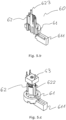
Fig. 3.a ,3.b and 3.b.2 show, in a compact and exploded form, a part of the device for controlling the water heating temperature according to the invention (sensors and part of the user regulation means are not shown). -
Figure 3.c shows a half-shell of the thermostat with regulation. -
Fig. 4 shows a "thermostat with regulation" with atemperature probe 115 and the connection with a user setting means. -
Figures 5.a and5.d show in a compact and exploded form the connection of a user setting means with an electromechanical transducer. -
Figures 5.b and 5.c show a detail of the kinematic chain in section and as a whole. -
Figure 6 shows the device for controlling the water heating temperature according to the invention, connected to the flange (the sensors and part of the user regulation means are not shown). -
Figures 7.a and 7.b show overall and exploded section views of the invention. - Any spatial references, unless otherwise indicated, refer to how the objects are represented in the figures.
- The features of a preferred variant of the invention are now described using the references in the figures. It is noted that the above figures, although schematic, reproduce the elements of the invention according to proportions among their spatial dimensions and orientations that are compatible with a possible embodiment.
- According to the prior art, the connection by wiring adapts to the geometry of the system characterised by a wide mechanical tolerance between the actuation block and the selector, wherein the actuation block is constrained to the
flange 103, the flange is constrained to thetank 113, thetank 113 is in turn constrained in a casing 114 acap 120 in which theselector 50 is positioned. - According to the invention, the problem is solved by integrating the electronic assemblies in a single device, i.e., said thermostat with
regulation 4 and this is made possible by a new kinematic chain actionable to regulate the temperature that overcomes the technical difficulties of the prior art. - The thermostat with
regulation 4 according to the invention comprises, (see in particular the Figs. from 3 onwards): - connections to the
temperature sensors 115, - a "thermostat board" 40 which in turn provides at least:
- actuators and connectors 102.b where the latter may also act as a connecting element with the
flange 103, - the microcontroller, with the necessary components and circuitry for its operation, the microcontroller (or equivalent electronic means) configured to thermostatically control the temperature,
- connectors 102.b for said
electrical heating elements 111; - fastening means 102.b to said
flange 103; - an
electromechanical transducer 43, such as, by way of an example, an encoder, a potentiometer or a trimmer capable of receiving a target temperature value of water, to be heated, represented by the amount of dragging of a draggedelement electromechanical transducer 43 is coupled, and sending it to said microcontroller;
- actuators and connectors 102.b where the latter may also act as a connecting element with the
- a kinematic chain 5 which starts from a
selector 50 of the target temperature couplable with a draggedelement 60, in turn couplable with saidelectromechanical transducer 43 with which the kinematic chain 5 ends (seeFigures 4, 5.a ,5.b, 5 .c ,5.d ). - Said
selector 50 is: - engaged in said dragged
element - capable of being slidingly couplable, with at least one degree of freedom directly or indirectly to the
casing 114 of the storage water heater 1 in a position accessible to the user, - where advantageously this sliding coupling takes place with a
cap 120 in turn constrained to thecasing 114. - Said kinematic chain 5 comprises at least one disengageable coupling so that the assembly and disassembly of said
selector 50 with respect to the draggedelement selector 50 and said draggedelement - Preferably said dragged
element 60 may in turn be a kinematic sub-chain composed of at least two mutually coupledparts first part 61 couplable to saidselector 50 and asecond part 62 couplable to saidelectromechanical transducer 43. - Preferably, there are provided:
- stop means such as an
end stop 424 consisting of mechanical stop means (see below) which prevent saidselector 50 from forcing theelectromechanical transducer 43 beyond its natural end stops; - support means 48 of said kinematic chain 5;
- a casing of dielectric material possibly according to the prior art and made with at least one covering half-
shell 48, which may usefully also act as said support means 48, and possible base half-shell 49, which protect at least saidthermostat board 40. - Said thermostat with
regulation 4 may have various dimensions, external shapes, mechanical constraint means and various electrical connections such as to be able to adapt and be positioned to previously available connection points in theflange 103 by means of saidconnectors 102 which may be the faston connections 102.a of one of the powered electrical resistances; as long as use of the thermostat withregulation 4 does not prompt possible advantageous design modifications of thetank 113 and of theflange 103 of the water heater wherein it is mounted in place of electronic board models of theprior art 10. - Said kinematic chain 5 therefore provides a dragged
element 60 or at least two mutually coupledelements - The described kinematic chain has the following advantages:
- it is robust despite the mechanical assembly tolerances between the
selector 50 and thetransducer 43 constrained to thetank 113; - even in presence of strong user stresses it does not damage the
electromechanical transducer 43. - Such sturdiness and lack of transmission of critical stresses is obtained by providing, between the
cap 120 and theelectromechanical transducer 43, at least a pair of mutually coupled elements, with a "slack"-type coupling, i.e., a coupling that can accept a clearance compatible with those that are normal manufacturing and assembly tolerances of the elements involved, such as for example, those due to shifts or inaccuracies of the relative distances with respect to the design theoretical ones, but sufficient to transmit to the draggedelement 60 the dragged and/or translatory movement (the latter not exemplified in the Figures) whichever is needed based on the design of theselector 50 and theelectromechanical transducer 43. The object is to have sufficient clearance to avoid unwanted stresses and deformations to the elements of the kinematic chain following theselector 50 which imparts their movement. - Said clearance may be provided between any two consecutive elements, while the remaining couplings in the kinematic chain 5 are preferred to be designed with tight mechanical tolerance, also for the stability of the assembly.
- According to a possible solution, said slack coupling may be obtained with a sufficient clearance between the
selector 50 and thecap 120 whereon it is slidingly or rotatably mounted. A simple but not preferred solution because the user would perceive the clearance as a rough execution and may also transmit harmful efforts along the kinematic chain 5. - Therefore, it is preferred that the coupling between the
selector 50 and the draggedelement 60 is of the slack type, i.e., that the coupling between theselector 50 and the draggedelement 60 is both of the disengageable and slack type. - Hereafter, the face of
selector 50 opposite the user will be referred to as "interior" 51, and "exterior", the face towards the user; at least the following couplings are possible between theselector 50 and the dragged element: - a slack male/female coupling where the male part is obtained in the interior 51 the
selector 50 and is inserted with clearance in a female seat obtained on the draggedelement 60; - a slack female/male coupling where the female seat is obtained in the
interior 51 of theselector 50 and the male part obtained on the draggedelement 60 is inserted with clearance therein; - a double fork coupling, each linked to the
selector 50 and to the draggedelement 60 where the teeth of said forks are inserted with clearance between each other; - a cardan-type joint or equivalent means that allow transmitting a rotation and/or translation movement without the need for coincidence of the rotation and/or sliding and precision axes (for example a flexible steel cable).
- In the preferred solution, the
selector 50 is arotatable knob 50 with a slack female/male shape coupling where saidselector 50 has a "cavity" 501 in the interior 51, adapted to engage one end of the draggedelement 60 which in this solution is substantially a pin, free to rotate with saidselector 50 and whose opposite "dragging end" 623 is inserted in saidelectromechanical transducer 43, which is of the rotatable type, so as to transmit to it the rotation angle of saidselector 50. For example, saidcavity 501 may constrain a "fin" 611 to rotate integrally with saidselector 50.Said fin 611 is obtained at one end of the draggedelement 60 and it is oriented radially with respect to the rotation axis of the draggedelement 60. Therefore, saidfin 611 has a lever function that facilitates the rotary movement of said draggedelement 60. - Advantageously, said dragged
element 60 may be composed of two parts mutually couplable with each other whereof afirst part 61 has a dragged end that may be coupled with saidselector 50 and asecond part 62 has the draggedend 623 that may be coupled with saidelectromechanical transducer 43. The realization with two distinct parts couplable with and constrainable to each other 61, 62 allows varying only thefirst part 61 coupled with theselector 50 according to the geometry of theselector 50, so that thethermostat board 40 may be used on different models of water heater 1. - The
first part 61 dragged by saidselector 50 may be a "lug" 61 wherein thefin 611 is obtained, the second part a "pin" 62 which in turn has a dragged end couplable with saidlug 61. By lug it is meant a crown element in which the central cavity has dimensions suitable for inserting therein saidpin 62, determining a shape coupling sufficiently tight so as not to allow slidings of thepin 62 with respect to thelug 61. In this solution, thelug 61 and in particular the length of thefin 611 may be made in different versions to adapt toselectors 50 with different geometries. Furthermore, saidpin 62 or saidlug 61 may have different heights to compensate for different distances provided between thethermostat board 40 and theselector 50. Advantageously, such variabilities between models are compensated for by the geometry of thelug 61. Nothing prevents theselector 50 from using knobs with a different geometry of the external part and the unvaried geometry for saidcavity 501 in the inner part. - The dragging
end 623 of said draggedelement electromechanical transducer 43. For example, said draggingend 623 inserts into saidelectromechanical transducer 43 with a shape coupling. - As said, the
thermostat board 40 is preferably protected by a casing comprising at least a covering half-shell 48, which provides a suitable "opening" 425 in which saidpin 62 is inserted on the side of the draggingend 623 being thus capable, if needed, to act also as a guide and/or support of saidpin 62. Advantageously, saidpin 62 may have one or more "arms" 622 adapted to form a mechanical constraint that prevents saidpin 62 from coming out of saidopening 425 once it has been inserted therein. For example, saidarms 622 may have a termination with an elastic snap-wise coupling. Advantageously, the length of saidarms 622 is such that the elastic coupling snaps when theend 623 of thepin 62 is correctly inserted for a length sufficient for the mechanical coupling to transmit the movement to theelectromechanical transducer 43 but less than that which could determine critical interferences with saidtransducer 43 or with the supporting printed circuit. Saidelectromechanical transducer 43, as known, may be of the trimmer type, with an allowed travel interval for its movable part, stresses beyond said interval may lead to breakage. - In the event that the
selector 50 is a knob and the draggedelement end 623, makes a rotary movement in theopening 425, it is advantageously possible to provide mechanical stop means which constitute movement end stop means for thepin pin opening 425 such that the sum of said first arc α and said second arc β is equal to the complementary angle with respect to the travel angle of saidelectromechanical transducer 43. This expedient prevents mechanical stresses that may cause the sameelectromechanical transducer 43 to break. - Not illustrated in the figures, it is also possible to provide the already said translational rather than rotary movement of the
selector 50 along guides in thecap 120, if theelectromechanical transducer 43 is a trimmer of the slider type. A slack coupling may be provided between theselector 50 and the draggedelement 60 and possibly a rocker arm with relative support means for the transmission of the translatory motion. - Also in the case of translatory motion, it is possible to provide an
end stop 424 made with mechanical stop means which blocks the movement of said draggedelement 60 before it brings the movable part of saidtransducer 43 beyond the allowed movement range thereof. - Thus, a thermostat with
regulation 4 is made which receives the signals from thetemperature sensors 115 and from aselector 50 which enables to set the target temperature. - The user interface may also provide one or more indicator lights, (for example LEDs) that may be mounted on the
thermostat board 40 and are visible through a window of the user interface. The light of the indicator lights may be guided from the origin to the user interface along a light guide (i.e., wave guide) which may also provide curves; therefore there are no particular constraints between the relative positions of light origin and the transparent window located on the user interface. - This flexibility in the type of mechanical and optical coupling enables not only the use of the thermostat with
regulation 4 in new water heater models 1 with interfaces of different geometry of the knobs and/or more display elements, but also the replacement in models already in production. - The invention also enables a fast and robust assembly method, which includes, by way of an example, the following steps for the variants that include the components listed below:
- a) rotating or translating the movable part of the
transducer 43, mounted on saidthermostat board 40, so that it is at the travel end (or beginning); - b) inserting the
thermostat board 40 between the "half-shells" 48 and 49 that make up the "shell" 48-49; - c) inserting the dragging
end 623 of thepin 62 into theopening 425; aligning the projectingpart 624 with the projection of theend stop 424; sliding theend 623 of thepin 62 into theopening 425 until the elastic coupling on thearm 622 snaps, which, once inserted creates an interference against the edge of theopening 425 that prevents thepin 62 from coming out; - d) inserting the
temperature probe 115 in itshousing 112; - e) constraining said
thermostat board 40 by means of said fastons 102.b to saidflange 103; - f) mounting the
lug 61 on thepin 62; - g) mounting said
cap 120 and theselector 50 at travel end (or beginning) so that it couples with thelug 61. - It is possible to carry out the step f) of mounting the
lug 61 onpin 62 even before step c), in this case it is preferable to make an interlocking coupling between thelug 61 andpin 62 so that once thelug 61 and thepin 62 are coupled they remain joined. - From the above description, the advantages that may be achieved with the use of said thermostat with
regulation 4 comprising said kinematic chain 5 in terms of strength, simplification of components and ease of assembly appear clear.
Claims (12)
- Thermostat with regulation (4) for controlling an electrical water heating element (111) for a storage water heater (1), the storage water heater comprising a flange (103), the flange (103) configured to be constrained to a tank (113), the tank (113) configured to be constrained to a casing (114), the casing (114) constrained to a cap (120), the cap (120) being coupled with a selector (50) of a target temperature for water in the storage water heater (1), the thermostat with regulation (4) configured to be constrainable to the flange (103) supporting the electrical water heating element (111), the thermostat with regulation (4) comprising:- an actuation block in turn comprising at least connections to a temperature sensor (115) and at least an actuator for the heating element (111),- the selector (50),- a microcontroller adapted to:- receive an input from the selector (50) of the target temperature for water in the storage water heater (1), by means of an electromechanical transducer (43), the electromechanical transducer (43) being one of an encoder, a potentiometer or a trimmer,- receive a signal from the at least one temperature sensor (115),- control the at least one actuator,and comprising integrated in a single device:- the connections to the at least one temperature sensor (115);- a thermostat board (40), in turn comprising:- electronic means for the control of the temperature for water in the storage water heater (1);- at least one electrical connector (102.b) for the power supply of said heating element (111);- fastening means (102.b) to the flange (103),- the electromechanical transducer (43),characterised in that the thermostat with regulation (4) further comprises:
a kinematic chain (5) connecting the selector (50) to the electromechanical transducer (43), the kinematic chain (5)starting from the selector (50), configured to engage a dragged element (60; 61)continuing with the dragged element (60; 61) which is couplable with said electromechanical transducer (43) with which the kinematic chain (5) ends wherein the kinematic chain (5) comprises a slack and disengageable coupling comprising a clearance between the selector (50) and the dragged element (60; 61). - Thermostat with regulation (4) according to claim 1, characterised in that said at least one electrical connector (102.b) coincide with the fastening means (102.b).
- Thermostat with regulation (4) according to any one of the previous claims, and further comprising mechanical stop means (624; 424) configured to prevent the dragged element (60, 62) from forcing a movable part of said transducer (43) beyond an allowed travel interval.
- Thermostat with regulation (4) according to any one of the previous claims,
characterised in that
said dragged element (60) comprises two parts mutually couplable to each other whereof a first dragged part (61) has an end couplable with said selector (50), and a second part (62) has a dragging end (623) couplable with said transducer (43). - Thermostat with regulation (4) according to any one of the previous claims,
characterised in that
said selector (50) is a knob (50) that may be rotated by a user and said transducer (43) is of the rotary type. - Thermostat with regulation (4) according to claims 4 and 5, characterised in that the dragged element (60) comprises a fin (611)
and the selector (50) in its inner part (51) comprises a cavity (501) adapted to engage the fin (611) and that the fin (611) is oriented radially with respect to the rotation axis of the dragged element (60) and has a lever function that facilitates the rotary movement of said dragged element (60). - Thermostat with regulation (4) according to claim 6, characterised in that
said first dragged part (61) is a lug (61) comprising the fin (611) that engages in the cavity (501) obtained inside (51) said selector (50) realising the slack and disengageable coupling and said second part (62) is a pin (62) couplable to said lug (61) and dragged therefrom, with a sufficiently tight coupling so as not to allow slidings of the pin (62) relative to the lug (61). - Thermostat with regulation (4) according to the previous claim, further comprising a casing, the casing comprising at least a covering half-shell (48) and wherein
said pin (62) at said dragging end (623) is inserted in a suitable opening (425) obtained on said half-shell (48) at said transducer (43) and has at least one arm (622) adapted to realise a mechanical constraint with an elastic coupling termination that prevents said pin (62) from coming out of said opening (425) once it has been inserted therein, where the length of said arm (622) is such that said elastic coupling termination snaps when said end (623) of said pin (62) is inserted for a length sufficient to transmit the movement to said transducer (43) but less than that which could cause critical interferences with said transducer (43) or with the supporting printed circuit. - Thermostat with regulation (4) according at least to claims 3, 4, and 5, further comprising a casing, the casing comprising at least a covering half-shell (48) and wherein
said dragged element (60, 62), at said dragging end (623), is inserted into a suitable opening (425) obtained on said half-shell (48) at said transducer (43), said mechanical stop means (624; 424) realising the travel end of said pin (62) comprising a curved projection (624) that increases the radius of said pin (62) for a first arc α, and an end stop (424) that describes a second arc β along the edge of said opening (425), such that the sum of said first arc α and said second arc β is equal to the supplementary angle with respect to the travel angle of said transducer (43). - Thermostat with regulation (4) according to any one among the previous claims, characterised in that said dragged element (60) comprises elements adapted to perform the functions of a cardan joint.
- Water heater (1) comprising a tank (113), a flange (103), an electric heating element (111), a temperature sensor (115), a casing (114), a cap (120) and a selector (50) wherein, the electric heating element (111) and temperature sensor (115) are constrained to the flange (103), the flange (103) is in turn constrained to the tank (113), the tank is constrained to the casing (114), the water heater (1) characterised in that it comprises: a thermostat with regulation (4) according to any one of claims 1 to 10 and in that the casing (114) is slidingly coupled with at least a degree of freedom to the selector (50).
- Water heater (1) according to the previous claim, characterised in that the selector (50) is slidingly coupled, with at least one degree of freedom and in a position accessible to the user, directly with a cap (120) in turn constrained to the casing (114).
Applications Claiming Priority (2)
| Application Number | Priority Date | Filing Date | Title |
|---|---|---|---|
| IT202100005786 | 2021-03-11 | ||
| PCT/IB2022/052139 WO2022190023A1 (en) | 2021-03-11 | 2022-03-10 | Integrated thermostat with regulation |
Publications (3)
| Publication Number | Publication Date |
|---|---|
| EP4305502A1 EP4305502A1 (en) | 2024-01-17 |
| EP4305502C0 EP4305502C0 (en) | 2025-06-04 |
| EP4305502B1 true EP4305502B1 (en) | 2025-06-04 |
Family
ID=76035015
Family Applications (1)
| Application Number | Title | Priority Date | Filing Date |
|---|---|---|---|
| EP22710445.2A Active EP4305502B1 (en) | 2021-03-11 | 2022-03-10 | Integrated thermostat with regulation |
Country Status (6)
| Country | Link |
|---|---|
| EP (1) | EP4305502B1 (en) |
| ES (1) | ES3040441T3 (en) |
| HU (1) | HUE072885T2 (en) |
| PL (1) | PL4305502T3 (en) |
| RO (1) | RO202300034U2 (en) |
| WO (1) | WO2022190023A1 (en) |
Family Cites Families (4)
| Publication number | Priority date | Publication date | Assignee | Title |
|---|---|---|---|---|
| AUPM520894A0 (en) * | 1994-04-20 | 1994-05-12 | Rheem Australia Pty Limited | An adaptor for a water heater thermostat |
| DE19853587A1 (en) * | 1998-11-20 | 2000-05-25 | Fahrzeugklimaregelung Gmbh | Switching device combining rotary potentiometer with push switch e.g. for motor vehicle heating or air conditioning system has push switch arranged inside hollow cylindrical shape of rotary potentiometer |
| US7346274B2 (en) * | 1999-07-27 | 2008-03-18 | Bradenbaugh Kenneth A | Water heater and method of controlling the same |
| US8587395B2 (en) * | 2012-04-03 | 2013-11-19 | Exelis, Inc. | Rotary encoder switch with pull function tactile feedback and positive stop |
-
2022
- 2022-03-10 WO PCT/IB2022/052139 patent/WO2022190023A1/en not_active Ceased
- 2022-03-10 PL PL22710445.2T patent/PL4305502T3/en unknown
- 2022-03-10 EP EP22710445.2A patent/EP4305502B1/en active Active
- 2022-03-10 HU HUE22710445A patent/HUE072885T2/en unknown
- 2022-03-10 RO ROU202300034U patent/RO202300034U2/en unknown
- 2022-03-10 ES ES22710445T patent/ES3040441T3/en active Active
Also Published As
| Publication number | Publication date |
|---|---|
| HUE072885T2 (en) | 2025-12-28 |
| RO202300034U2 (en) | 2025-03-28 |
| ES3040441T3 (en) | 2025-10-30 |
| WO2022190023A1 (en) | 2022-09-15 |
| EP4305502C0 (en) | 2025-06-04 |
| PL4305502T3 (en) | 2025-09-22 |
| EP4305502A1 (en) | 2024-01-17 |
Similar Documents
| Publication | Publication Date | Title |
|---|---|---|
| EP2856030B1 (en) | Gas appliance control device | |
| US9696041B2 (en) | Control device for gas taps | |
| EP3172942B1 (en) | Heating element control circuit | |
| US9706872B2 (en) | Control device for gas taps | |
| CN110325795B (en) | Knob assembly and cooking apparatus including the same | |
| US20150050827A1 (en) | Cable connector with switching structure | |
| EP1895624B1 (en) | Infrared heat irradiating device | |
| US20060027446A1 (en) | Method and apparatus for selectively locking a standard plug to a standard receptacle | |
| KR20040012908A (en) | Switchgear comprising an actuating shaft | |
| WO2022190023A1 (en) | Integrated thermostat with regulation | |
| AU762918B2 (en) | An electrical switch for gas cocks | |
| JPS5935613B2 (en) | Electric cooking plate with overheat protection switch | |
| NZ194469A (en) | Electric kettle switch on dry and steam switch construction and mechanism | |
| US7633017B2 (en) | Integrated junction box operable with gas valve | |
| CN1114221C (en) | Improvements relating to electrically powered water heating appliances and controls therefor | |
| JPH04241899A (en) | Electric steam iron | |
| EP3553395A1 (en) | Actuator, heating circuit manifold, and procedure for installing actuator in heating circuit manifold | |
| CN113412526B (en) | Modular electronic devices for electrical and/or home automation systems | |
| WO2000027670A1 (en) | Electrically controlled mirror for a motor vehicle | |
| GB9520114D0 (en) | Gear cable operating mechanism | |
| JP3565389B2 (en) | Automatic faucet | |
| JPH054234Y2 (en) | ||
| WO2026015159A1 (en) | Remote switch adapter assembly and associated methods of use | |
| JP5441771B2 (en) | Built-in cooking device | |
| EP3772613A1 (en) | A transmission mechanism for push-button switches |
Legal Events
| Date | Code | Title | Description |
|---|---|---|---|
| STAA | Information on the status of an ep patent application or granted ep patent |
Free format text: STATUS: UNKNOWN |
|
| STAA | Information on the status of an ep patent application or granted ep patent |
Free format text: STATUS: THE INTERNATIONAL PUBLICATION HAS BEEN MADE |
|
| PUAI | Public reference made under article 153(3) epc to a published international application that has entered the european phase |
Free format text: ORIGINAL CODE: 0009012 |
|
| STAA | Information on the status of an ep patent application or granted ep patent |
Free format text: STATUS: REQUEST FOR EXAMINATION WAS MADE |
|
| 17P | Request for examination filed |
Effective date: 20231006 |
|
| AK | Designated contracting states |
Kind code of ref document: A1 Designated state(s): AL AT BE BG CH CY CZ DE DK EE ES FI FR GB GR HR HU IE IS IT LI LT LU LV MC MK MT NL NO PL PT RO RS SE SI SK SM TR |
|
| P01 | Opt-out of the competence of the unified patent court (upc) registered |
Effective date: 20240318 |
|
| DAV | Request for validation of the european patent (deleted) | ||
| DAX | Request for extension of the european patent (deleted) | ||
| RIN1 | Information on inventor provided before grant (corrected) |
Inventor name: VIVIANI, SIMONE Inventor name: NERI, GIAMPAOLO Inventor name: MORECI, RENATO Inventor name: ROTILI, RUDY Inventor name: COACCI, GIANLUCA |
|
| STAA | Information on the status of an ep patent application or granted ep patent |
Free format text: STATUS: EXAMINATION IS IN PROGRESS |
|
| 17Q | First examination report despatched |
Effective date: 20240930 |
|
| RAP1 | Party data changed (applicant data changed or rights of an application transferred) |
Owner name: THERMOWATT S.P.A. Owner name: ARISTON S.P.A. |
|
| GRAP | Despatch of communication of intention to grant a patent |
Free format text: ORIGINAL CODE: EPIDOSNIGR1 |
|
| STAA | Information on the status of an ep patent application or granted ep patent |
Free format text: STATUS: GRANT OF PATENT IS INTENDED |
|
| INTG | Intention to grant announced |
Effective date: 20250307 |
|
| GRAS | Grant fee paid |
Free format text: ORIGINAL CODE: EPIDOSNIGR3 |
|
| GRAA | (expected) grant |
Free format text: ORIGINAL CODE: 0009210 |
|
| STAA | Information on the status of an ep patent application or granted ep patent |
Free format text: STATUS: THE PATENT HAS BEEN GRANTED |
|
| AK | Designated contracting states |
Kind code of ref document: B1 Designated state(s): AL AT BE BG CH CY CZ DE DK EE ES FI FR GB GR HR HU IE IS IT LI LT LU LV MC MK MT NL NO PL PT RO RS SE SI SK SM TR |
|
| REG | Reference to a national code |
Ref country code: GB Ref legal event code: FG4D |
|
| REG | Reference to a national code |
Ref country code: CH Ref legal event code: EP |
|
| REG | Reference to a national code |
Ref country code: DE Ref legal event code: R096 Ref document number: 602022015483 Country of ref document: DE |
|
| REG | Reference to a national code |
Ref country code: IE Ref legal event code: FG4D |
|
| U01 | Request for unitary effect filed |
Effective date: 20250701 |
|
| U07 | Unitary effect registered |
Designated state(s): AT BE BG DE DK EE FI FR IT LT LU LV MT NL PT RO SE SI Effective date: 20250708 |
|
| PG25 | Lapsed in a contracting state [announced via postgrant information from national office to epo] |
Ref country code: GR Free format text: LAPSE BECAUSE OF FAILURE TO SUBMIT A TRANSLATION OF THE DESCRIPTION OR TO PAY THE FEE WITHIN THE PRESCRIBED TIME-LIMIT Effective date: 20250905 Ref country code: NO Free format text: LAPSE BECAUSE OF FAILURE TO SUBMIT A TRANSLATION OF THE DESCRIPTION OR TO PAY THE FEE WITHIN THE PRESCRIBED TIME-LIMIT Effective date: 20250904 |
|
| PG25 | Lapsed in a contracting state [announced via postgrant information from national office to epo] |
Ref country code: HR Free format text: LAPSE BECAUSE OF FAILURE TO SUBMIT A TRANSLATION OF THE DESCRIPTION OR TO PAY THE FEE WITHIN THE PRESCRIBED TIME-LIMIT Effective date: 20250604 |
|
| PG25 | Lapsed in a contracting state [announced via postgrant information from national office to epo] |
Ref country code: RS Free format text: LAPSE BECAUSE OF FAILURE TO SUBMIT A TRANSLATION OF THE DESCRIPTION OR TO PAY THE FEE WITHIN THE PRESCRIBED TIME-LIMIT Effective date: 20250904 |
|
| REG | Reference to a national code |
Ref country code: ES Ref legal event code: FG2A Ref document number: 3040441 Country of ref document: ES Kind code of ref document: T3 Effective date: 20251030 |
|
| REG | Reference to a national code |
Ref country code: HU Ref legal event code: AG4A Ref document number: E072885 Country of ref document: HU |
|
| PG25 | Lapsed in a contracting state [announced via postgrant information from national office to epo] |
Ref country code: IS Free format text: LAPSE BECAUSE OF FAILURE TO SUBMIT A TRANSLATION OF THE DESCRIPTION OR TO PAY THE FEE WITHIN THE PRESCRIBED TIME-LIMIT Effective date: 20251004 |
|
| PG25 | Lapsed in a contracting state [announced via postgrant information from national office to epo] |
Ref country code: SM Free format text: LAPSE BECAUSE OF FAILURE TO SUBMIT A TRANSLATION OF THE DESCRIPTION OR TO PAY THE FEE WITHIN THE PRESCRIBED TIME-LIMIT Effective date: 20250604 |
|
| PG25 | Lapsed in a contracting state [announced via postgrant information from national office to epo] |
Ref country code: CZ Free format text: LAPSE BECAUSE OF FAILURE TO SUBMIT A TRANSLATION OF THE DESCRIPTION OR TO PAY THE FEE WITHIN THE PRESCRIBED TIME-LIMIT Effective date: 20250604 |
|
| PG25 | Lapsed in a contracting state [announced via postgrant information from national office to epo] |
Ref country code: SK Free format text: LAPSE BECAUSE OF FAILURE TO SUBMIT A TRANSLATION OF THE DESCRIPTION OR TO PAY THE FEE WITHIN THE PRESCRIBED TIME-LIMIT Effective date: 20250604 |
|
| PLBE | No opposition filed within time limit |
Free format text: ORIGINAL CODE: 0009261 |
|
| STAA | Information on the status of an ep patent application or granted ep patent |
Free format text: STATUS: NO OPPOSITION FILED WITHIN TIME LIMIT |
|
| U20 | Renewal fee for the european patent with unitary effect paid |
Year of fee payment: 5 Effective date: 20260306 |
|
| PGFP | Annual fee paid to national office [announced via postgrant information from national office to epo] |
Ref country code: HU Payment date: 20260323 Year of fee payment: 5 |
|
| REG | Reference to a national code |
Ref country code: CH Ref legal event code: L10 Free format text: ST27 STATUS EVENT CODE: U-0-0-L10-L00 (AS PROVIDED BY THE NATIONAL OFFICE) Effective date: 20260416 |
|
| PGFP | Annual fee paid to national office [announced via postgrant information from national office to epo] |
Ref country code: PL Payment date: 20260226 Year of fee payment: 5 |
|
| 26N | No opposition filed |
Effective date: 20260305 |