EP4305331B1 - Fernverbundener/getrennter hochtemperaturrohrverbinder für salzschmelzereaktoren - Google Patents
Fernverbundener/getrennter hochtemperaturrohrverbinder für salzschmelzereaktoren Download PDFInfo
- Publication number
- EP4305331B1 EP4305331B1 EP22768088.1A EP22768088A EP4305331B1 EP 4305331 B1 EP4305331 B1 EP 4305331B1 EP 22768088 A EP22768088 A EP 22768088A EP 4305331 B1 EP4305331 B1 EP 4305331B1
- Authority
- EP
- European Patent Office
- Prior art keywords
- pipe connector
- pin
- box
- seal ring
- threads
- Prior art date
- Legal status (The legal status is an assumption and is not a legal conclusion. Google has not performed a legal analysis and makes no representation as to the accuracy of the status listed.)
- Active
Links
Images






Classifications
-
- F—MECHANICAL ENGINEERING; LIGHTING; HEATING; WEAPONS; BLASTING
- F16—ENGINEERING ELEMENTS AND UNITS; GENERAL MEASURES FOR PRODUCING AND MAINTAINING EFFECTIVE FUNCTIONING OF MACHINES OR INSTALLATIONS; THERMAL INSULATION IN GENERAL
- F16L—PIPES; JOINTS OR FITTINGS FOR PIPES; SUPPORTS FOR PIPES, CABLES OR PROTECTIVE TUBING; MEANS FOR THERMAL INSULATION IN GENERAL
- F16L19/00—Joints in which sealing surfaces are pressed together by means of a member, e.g. a swivel nut, screwed on, or into, one of the joint parts
- F16L19/02—Pipe ends provided with collars or flanges, integral with the pipe or not, pressed together by a screwed member
- F16L19/025—Pipe ends provided with collars or flanges, integral with the pipe or not, pressed together by a screwed member the pipe ends having integral collars or flanges
- F16L19/028—Pipe ends provided with collars or flanges, integral with the pipe or not, pressed together by a screwed member the pipe ends having integral collars or flanges the collars or flanges being obtained by deformation of the pipe wall
- F16L19/0286—Pipe ends provided with collars or flanges, integral with the pipe or not, pressed together by a screwed member the pipe ends having integral collars or flanges the collars or flanges being obtained by deformation of the pipe wall and being formed as a flange
-
- F—MECHANICAL ENGINEERING; LIGHTING; HEATING; WEAPONS; BLASTING
- F16—ENGINEERING ELEMENTS AND UNITS; GENERAL MEASURES FOR PRODUCING AND MAINTAINING EFFECTIVE FUNCTIONING OF MACHINES OR INSTALLATIONS; THERMAL INSULATION IN GENERAL
- F16L—PIPES; JOINTS OR FITTINGS FOR PIPES; SUPPORTS FOR PIPES, CABLES OR PROTECTIVE TUBING; MEANS FOR THERMAL INSULATION IN GENERAL
- F16L15/00—Screw-threaded joints; Forms of screw-threads for such joints
- F16L15/006—Screw-threaded joints; Forms of screw-threads for such joints with straight threads
- F16L15/007—Screw-threaded joints; Forms of screw-threads for such joints with straight threads with more than one threaded section
-
- F—MECHANICAL ENGINEERING; LIGHTING; HEATING; WEAPONS; BLASTING
- F16—ENGINEERING ELEMENTS AND UNITS; GENERAL MEASURES FOR PRODUCING AND MAINTAINING EFFECTIVE FUNCTIONING OF MACHINES OR INSTALLATIONS; THERMAL INSULATION IN GENERAL
- F16J—PISTONS; CYLINDERS; SEALINGS
- F16J15/00—Sealings
- F16J15/02—Sealings between relatively-stationary surfaces
- F16J15/06—Sealings between relatively-stationary surfaces with solid packing compressed between sealing surfaces
- F16J15/08—Sealings between relatively-stationary surfaces with solid packing compressed between sealing surfaces with exclusively metal packing
- F16J15/0881—Sealings between relatively-stationary surfaces with solid packing compressed between sealing surfaces with exclusively metal packing the sealing effect being obtained by plastic deformation of the packing
-
- F—MECHANICAL ENGINEERING; LIGHTING; HEATING; WEAPONS; BLASTING
- F16—ENGINEERING ELEMENTS AND UNITS; GENERAL MEASURES FOR PRODUCING AND MAINTAINING EFFECTIVE FUNCTIONING OF MACHINES OR INSTALLATIONS; THERMAL INSULATION IN GENERAL
- F16L—PIPES; JOINTS OR FITTINGS FOR PIPES; SUPPORTS FOR PIPES, CABLES OR PROTECTIVE TUBING; MEANS FOR THERMAL INSULATION IN GENERAL
- F16L15/00—Screw-threaded joints; Forms of screw-threads for such joints
- F16L15/006—Screw-threaded joints; Forms of screw-threads for such joints with straight threads
- F16L15/008—Screw-threaded joints; Forms of screw-threads for such joints with straight threads with sealing rings
-
- F—MECHANICAL ENGINEERING; LIGHTING; HEATING; WEAPONS; BLASTING
- F16—ENGINEERING ELEMENTS AND UNITS; GENERAL MEASURES FOR PRODUCING AND MAINTAINING EFFECTIVE FUNCTIONING OF MACHINES OR INSTALLATIONS; THERMAL INSULATION IN GENERAL
- F16L—PIPES; JOINTS OR FITTINGS FOR PIPES; SUPPORTS FOR PIPES, CABLES OR PROTECTIVE TUBING; MEANS FOR THERMAL INSULATION IN GENERAL
- F16L19/00—Joints in which sealing surfaces are pressed together by means of a member, e.g. a swivel nut, screwed on, or into, one of the joint parts
- F16L19/005—Joints in which sealing surfaces are pressed together by means of a member, e.g. a swivel nut, screwed on, or into, one of the joint parts comprising locking means for the threaded member
-
- F—MECHANICAL ENGINEERING; LIGHTING; HEATING; WEAPONS; BLASTING
- F16—ENGINEERING ELEMENTS AND UNITS; GENERAL MEASURES FOR PRODUCING AND MAINTAINING EFFECTIVE FUNCTIONING OF MACHINES OR INSTALLATIONS; THERMAL INSULATION IN GENERAL
- F16L—PIPES; JOINTS OR FITTINGS FOR PIPES; SUPPORTS FOR PIPES, CABLES OR PROTECTIVE TUBING; MEANS FOR THERMAL INSULATION IN GENERAL
- F16L19/00—Joints in which sealing surfaces are pressed together by means of a member, e.g. a swivel nut, screwed on, or into, one of the joint parts
- F16L19/02—Pipe ends provided with collars or flanges, integral with the pipe or not, pressed together by a screwed member
- F16L19/0212—Pipe ends provided with collars or flanges, integral with the pipe or not, pressed together by a screwed member using specially adapted sealing means
-
- F—MECHANICAL ENGINEERING; LIGHTING; HEATING; WEAPONS; BLASTING
- F16—ENGINEERING ELEMENTS AND UNITS; GENERAL MEASURES FOR PRODUCING AND MAINTAINING EFFECTIVE FUNCTIONING OF MACHINES OR INSTALLATIONS; THERMAL INSULATION IN GENERAL
- F16L—PIPES; JOINTS OR FITTINGS FOR PIPES; SUPPORTS FOR PIPES, CABLES OR PROTECTIVE TUBING; MEANS FOR THERMAL INSULATION IN GENERAL
- F16L19/00—Joints in which sealing surfaces are pressed together by means of a member, e.g. a swivel nut, screwed on, or into, one of the joint parts
- F16L19/02—Pipe ends provided with collars or flanges, integral with the pipe or not, pressed together by a screwed member
- F16L19/0212—Pipe ends provided with collars or flanges, integral with the pipe or not, pressed together by a screwed member using specially adapted sealing means
- F16L19/0218—Pipe ends provided with collars or flanges, integral with the pipe or not, pressed together by a screwed member using specially adapted sealing means comprising only sealing rings
-
- F—MECHANICAL ENGINEERING; LIGHTING; HEATING; WEAPONS; BLASTING
- F16—ENGINEERING ELEMENTS AND UNITS; GENERAL MEASURES FOR PRODUCING AND MAINTAINING EFFECTIVE FUNCTIONING OF MACHINES OR INSTALLATIONS; THERMAL INSULATION IN GENERAL
- F16L—PIPES; JOINTS OR FITTINGS FOR PIPES; SUPPORTS FOR PIPES, CABLES OR PROTECTIVE TUBING; MEANS FOR THERMAL INSULATION IN GENERAL
- F16L19/00—Joints in which sealing surfaces are pressed together by means of a member, e.g. a swivel nut, screwed on, or into, one of the joint parts
- F16L19/02—Pipe ends provided with collars or flanges, integral with the pipe or not, pressed together by a screwed member
- F16L19/025—Pipe ends provided with collars or flanges, integral with the pipe or not, pressed together by a screwed member the pipe ends having integral collars or flanges
-
- F—MECHANICAL ENGINEERING; LIGHTING; HEATING; WEAPONS; BLASTING
- F16—ENGINEERING ELEMENTS AND UNITS; GENERAL MEASURES FOR PRODUCING AND MAINTAINING EFFECTIVE FUNCTIONING OF MACHINES OR INSTALLATIONS; THERMAL INSULATION IN GENERAL
- F16L—PIPES; JOINTS OR FITTINGS FOR PIPES; SUPPORTS FOR PIPES, CABLES OR PROTECTIVE TUBING; MEANS FOR THERMAL INSULATION IN GENERAL
- F16L59/00—Thermal insulation in general
- F16L59/14—Arrangements for the insulation of pipes or pipe systems
- F16L59/16—Arrangements specially adapted to local requirements at flanges, junctions, valves or the like
- F16L59/18—Arrangements specially adapted to local requirements at flanges, junctions, valves or the like adapted for joints
-
- F—MECHANICAL ENGINEERING; LIGHTING; HEATING; WEAPONS; BLASTING
- F16—ENGINEERING ELEMENTS AND UNITS; GENERAL MEASURES FOR PRODUCING AND MAINTAINING EFFECTIVE FUNCTIONING OF MACHINES OR INSTALLATIONS; THERMAL INSULATION IN GENERAL
- F16L—PIPES; JOINTS OR FITTINGS FOR PIPES; SUPPORTS FOR PIPES, CABLES OR PROTECTIVE TUBING; MEANS FOR THERMAL INSULATION IN GENERAL
- F16L2201/00—Special arrangements for pipe couplings
- F16L2201/40—Special arrangements for pipe couplings for special environments
-
- Y—GENERAL TAGGING OF NEW TECHNOLOGICAL DEVELOPMENTS; GENERAL TAGGING OF CROSS-SECTIONAL TECHNOLOGIES SPANNING OVER SEVERAL SECTIONS OF THE IPC; TECHNICAL SUBJECTS COVERED BY FORMER USPC CROSS-REFERENCE ART COLLECTIONS [XRACs] AND DIGESTS
- Y02—TECHNOLOGIES OR APPLICATIONS FOR MITIGATION OR ADAPTATION AGAINST CLIMATE CHANGE
- Y02E—REDUCTION OF GREENHOUSE GAS [GHG] EMISSIONS, RELATED TO ENERGY GENERATION, TRANSMISSION OR DISTRIBUTION
- Y02E30/00—Energy generation of nuclear origin
- Y02E30/30—Nuclear fission reactors
Definitions
- pipe connectors Disclosed herein are pipe connectors, and more particularly, pipe connectors for use in high temperatures, such as in molten salt reactors.
- the flange design uses a flange at one end of a pipe that extends radially outward from the pipe with holes around the outer periphery of the flange for bolting together with another flange from a different pipe.
- a gasket is generally placed between the two flanges, which provides a seal to prevent fluids or gases from leaking through the connection.
- the clamp design has a hub that extends radially outward with a taper on the outside surface. Two clamps engage the taper surface with holes for bolting the two together.
- a gasket is positioned between the two clamp hubs, which provides a seal to prevent fluids or gases from leaking through the connection.
- a pipe connector (1) comprising, a cylindrical pin (4) defining a passage therethrough, the pin comprising: a first portion, a second portion, and a transition portion extending from the first portion to the second portion, and the second portion having a plurality of threads extending outwardly from the outer surface of the second portion; and a ledge extending inwardly from the internal surface of the pin, the ledge defining a groove therein (see Fig.
- a cylindrical seal ring (3) defining a passage therethrough, the seal ring inserted within the pin the passage of the seal ring being aligned with the passage of the pin; a retainer ring (31) positioned within the groove formed in the ledge, a cylindrical box (6) having a first end (7) and a second end and defining a passage extending therethrough the box defining a groove formed at the first end (see Fig. 20c), the first end of the box inserted into the pin wherein the first end surrounds a portion of the seal ring (3) and is positioned between the seal ring (3) and the pin (4), the passage of the box being aligned with the passage of the seal ring (see Fig.
- a cylindrical locking nut (8) defining a passage therethrough and comprising a plurality of threads extending inwardly from the internal surface of the locking nut, the locking nut positioned around the pin (4) and the box (6) and being threadedly coupled to the plurality of threads.
- the exemplary embodiment disclosed herein is directed to pipe connectors, and more particularly to pipe connectors for use in high temperature environments, such as those characteristics of molten salt reactors.
- the pipe connector described herein can be used in any industry that uses pipe connectors.
- the exemplary pipe connectors can be used in building a molten salt system including a reactor or any other industry (e.g., the petroleum industry, in particular the refining sector) requiring a connection rated for temperatures over 700°C and pressures up to 103421.35 kPa (15,000 psi).
- the exemplary pipe connector maintains a seal connection between pipes at temperatures greater than about 700°C, or greater than about 725°C.
- the temperature at which the pipe connector can used is not particularly limited.
- the pipe connectors can maintain a seal connection between pipes at temperatures in the range of about -20 °C to about 1000°C, about -20 °C to about 900°C, or about -20°C to about 800°C.
- the pipe connectors are suitable for use across a wide range of pressures.
- the exemplary pipe connectors can be used at pressures ranging from atmospheric up to about 13789.51 kPa (2000 psi), from atmospheric to about 34473.78 kPa (5000 psi), from atmospheric to about 68947.57 kPa (10,000 psi), or from atmospheric to about 103421.35 kPa (15,000 psi).
- the exemplary pipe connectors may comprise certain design modifications to accommodate higher pressure, for example changing the outer diameter to increase the strength of the exemplary pipe connector.
- the exemplary pipe connector is required to operate at a temperature of about 725°C and a pressure up to 689.47 kPa (100 psi).
- molten salt means a salt which is solid at standard temperature and pressure but enters the liquid phase due to elevated temperature.
- FIGS. 1-4 show cross-sectional or external views of a pipe connector 100 in accordance with an exemplary embodiment.
- FIG. 1 shows a cross-sectional exploded view of the pipe connector 100 in accordance with the exemplary embodiment.
- FIG. 2 shows an external view of the pipe connector 100 of FIG. 1 .
- FIG. 3 shows an external assembled view of the pipe connector of FIG. 1 in accordance with the exemplary embodiment.
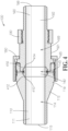
- FIG. 4 shows a cross-sectional assembled view of the pipe connector of FIG. 1 illustrating the seal connections between the pin 110 and the box 160 with seal ring 140 in accordance with the exemplary embodiment.
- the pipe connector 100 includes a pin 110, a seal ring 140, a retainer ring 150, a box 160, a locking nut 180, and a retaining nut 190 according to certain exemplary embodiments.
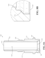
- the pin 110 is cylindrical in shape and includes a first portion 111, a second portion 113, and a transition portion 112 extending between the first portion 111 and the second portion 113.
- the pin 110 defines a passage 114 extending therethrough for fluid, either liquids or gases, to flow therethrough.
- the first portion 111 extends from a first end 115 of the pin 110 to the transition portion 112 and has a smooth internal surface having a constant circumference according to the exemplary embodiment; however, the internal surface may not be smooth or not have a constant circumference in other embodiments.
- the transition portion 112 extends from the first portion 111 to the second portion 113.
- the outer surface of the transition portion 112 gradually increases in circumference as the transition portion 112 extends from the first portion 111 to a transition point 116 located along the transition portion's 112 outer surface, wherein the transition portion's 112 outer surface then has a circumference that is constant as the outer surface extends from the transition point 116 to the second portion 113.
- the transition portion 112 also includes a plurality of threads 117 extending outwardly from its outer surface adjacent to the second portion 113.
- the internal surface of the transition portion 112 is smooth and has a constant circumference which is the same as the internal circumference of the first portion 111; however, the circumference of the internal surface is larger towards its end adjacent the second portion 113, thereby causing the end of the transition portion 112 adjacent the second portion 113 to have a first thickness 118.
- the internal surface of the transition portion 112 adjacent the second portion 113 has first groove 119 and a second groove 120 formed therein, wherein the second groove 120 is formed deeper that the first groove 119.
- the second portion 113 extends from the end of the transition portion 112 to a second end 121 of the pin 110.
- the second portion 113 includes a plurality of threads 122 extending outwardly from its outer surface adjacent the second end 121.
- the second portion's outer surface is the same circumference at the end of the transition portion 112 located adjacent the second portion 113.
- the second portion's internal surface is smooth and has a larger circumference than the circumference of the transition portion's internal surface located adjacent the second portion 113, thereby causing the second portion to have a second thickness 123.
- the second thickness 123 is less than the first thickness 118, thereby forming a ledge 124 where the transition portion 112 transitions to the second portion 113.
- the ledge 124 includes a third groove 125 formed within its internal surface.
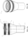
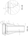
- FIGS. 5A, 5B , 6A and 6B show cross-sectional or perspective views of a pin 110 in accordance with an exemplary embodiment.
- the seal ring 140 is cylindrical in shape and includes a first ridge 141 and a second ridge 142 extending outwardly from the outer surface adjacent each of its ends.
- the first ridge 141 is configured to fit within the second groove 120 and the end of the seal ring 140 adjacent the first ridge 141 is configured to rest atop and adjacent the first groove 119.
- the seal ring 140 defines a passage 143 extending therethrough for fluid, either liquids or gases, to flow therethrough.
- the seal ring's internal surface is smooth and has a circumference that is equal to the circumference of the pin's first portion's 111 internal surface such that diameter or circumference of passage 114 extending from the first portion 111 to the transition portion 112 to the seal ring 140 is the same once the seal ring 140 is installed within the pin 110.
- FIGS. 9A, 9B , 10A and 10B show cross-sectional or perspective views of a seal ring 140 in accordance with an exemplary embodiment.
- the retainer ring 150 is ring shaped and is configured to fit within the third groove 125.
- the retainer ring 150 also is configured to be positioned around the seal ring 140 between the first ridge 141 and the second ridge 142 once the retainer ring 150 is installed within the pin 110.
- the box 160 is cylindrical in shape and includes a first portion 161 and a second portion 162 extending from the end of the first portion 161.
- the box 160 defines a passage 169 extending therethrough for fluid, either liquids or gases, to flow therethrough.
- the first portion 161 extends from a first end 163 of the box 160 to the second portion 162 and has a substantially smooth internal surface having a constant circumference, except for a groove 164 formed at the first end 163 of the box 160.
- the groove 164 is configured to allow the box's first end 163 to be inserted into the pin's second end 122 and fit adjacently around the seal ring's second ridge 142 and the seal ring's end between the seal ring 140 and the pin 110.
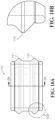
- the internal surface of passage 169 has first groove 164 and a second groove 170 formed therein, wherein the second groove 170 is formed deeper that the first groove 164, as shown in FIG. 8B .
- the first portion's 161 internal surface has a circumference or diameter that is the same as the circumference or diameter of the pin's first portion 111.
- the first portion's 161 outer surface has a circumference that is constant as the outer surface extends from the first end 163 to the second portion 162 but includes a ridge 165 extending outwardly therefrom adjacent the first end 163.
- the first portion's 161 outer surface is dimensioned to fit within the pin's second portion's 113 inner surface and the ridge 165 extends sufficiently outward from the first portion's 161 outer surface to be equal to the circumference of the pin's second portion's 113 outer surface once the box's first portion 161 is nstallled within the pin's second portion 113.
- the second portion 162 extends from the first portion to a second end 166 of the box 160 and has a smooth internal surface having a constant circumference.
- the second portion's 162 internal surface has a circumference or diameter that is the same as the circumference or diameter of the box's first portion 161.
- the outer surface of the second portion 162 has a diameter or circumference that is smaller than the outer surface or diameter of the first portion's 161 outer surface, thereby causing the second portion 162 to have a smaller thickness than the first portion 161 and forming a ledge 167 where the first portion 161 transitions to the second portion 162.
- the second portion 162 includes a plurality of threads 168 extending outwardly from its outer surface adjacent to the end of the box's first portion 161.
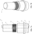
- FIGS. 7A, 7B , 8A and 8B show cross-sectional or perspective views of a box 160 in accordance with an exemplary embodiment.
- the locking nut 180 is cylindrical in shape and extends from a first end 181 to a second end 182.
- the locking nut 180 defines a passage 183 extending therethrough for allowing the box's second portion 162 and a portion of the box's first portion 161 to pass therethrough.
- the locking nut 180 includes a first internal ridge 184 formed at the second end 182, which extends inwardly from the internal surface of the locking nut 180.
- the locking nut 180 also includes a second internal ridge 185 formed adjacent the first internal ridge 184, which extends inwardly from the internal surface of the locking nut 180 but not as far as the first internal ridge 184 extends.
- the locking nut 180 further includes a plurality of threads 186 extending inwardly from its inner surface extending from the first end 181 to the second internal ridge 185.
- the locking nut 180 is configured to be coupled around a portion of the pin 110 and a portion of the box 160.
- FIGS. 11A, 11B and 12 show cross-sectional or perspective views of a locking nut 180 in accordance with an exemplary embodiment.
- the retaining nut 190 is cylindrical in shape and extends from a first end 191 to a second end 192.
- the retaining nut 190 defines a passage 193 extending therethrough for allowing a portion of the box's second portion 162 to pass therethrough.
- the retaining nut 190 includes a plurality of threads 194 extending inwardly from its inner surface extending from the first end 191 towards the second end 192, and in some embodiments, the plurality of threads extends entirely to the second end 192.
- the retaining nut 190 is configured to be coupled around a portion of the box's second portion 162 that is adjacent the box's first portion 161.
- FIGS. 13A, 13B and 14 show cross-sectional or perspective views of a retaining nut 190 in accordance with an exemplary embodiment.
- assembly of the pipe connector 100 occurs by first inserting the retainer ring 150 into the pin's third groove 125 in the ledge 124.
- the seal ring 140 is inserted into the pin 110 such that the seal ring's first ridge 141 is inserted and secured into the pin's second groove 120 and the end of the seal ring 140 adjacent the first ridge 141 rests atop and adjacent the pin's first groove 119.
- the seal ring's second ridge 142 is positioned adjacent to and rests on the pin's ledge 124 on the opposite side of the pin's ledge 124 than where the first ridge 141 is positioned.
- the seal ring's passage 143 is positioned adjacent to and abuts the pin's passage 114 that extends from the pin's first portion 111, thereby making passage 114 and passage 143 continuous and smooth with a constant internal circumference or diameter.
- a portion of the box 160 is inserted into the pin 110 and around the seal ring 140 according to the exemplary embodiment.
- the connection of the box 160 to the pin 110 is not secured at this time and can easily be removed.
- the box 160 is set in place.
- the box's ridge 165 is positioned adjacent to and abutting the pin's second end 121.
- the locking nut 180 slides over the box 160 and the locking nut's plurality of threads 186 engages the pin's second portion's plurality of threads 122.
- the locking nut 180 is rotated so that the locking nut's plurality of threads 186 is coupled to the pin's second portion's plurality of threads 122 and then eventually also couples to the pin's transition portion's plurality of threads 117.
- the locking nut's first internal ridge 184 provides a stop for the locking nut 180 once the first internal ridge 184 abuts the box's ridge 165.
- the box 160 is securely coupled to the pin 110.
- the seal ring 140 is compressed and seals the connection between the pin 110 and the box 160.
- the box's passage 169 is positioned adjacent to and abuts the seal ring's passage 143, thereby making passage 114, passage 143, and passage 169 continuous and smooth with a constant internal circumference or diameter.
- the retaining nut 190 slides over a portion of the box 160 and the retaining nut's plurality of threads 194 engages the box's second portion's plurality of threads 168.
- the retaining nut 190 is rotated so that the retaining nut's plurality of threads 194 is coupled to the box's second portion's plurality of threads 168.
- the retaining nut 190 is threaded (lefthand thread) onto the box's second portion's plurality of threads 168.
- the box's ledge 167 provides a stop for the retaining nut 190 once the retaining nut's first end 191 abuts the box's ledge 167.
- the retaining nut 190 is used for disassembly of the pipe connector 100.
- breaking the seal between the pin 110 and the box 160 is achieved by rotating the locking nut 180 backwards and moving the locking nut 180 towards the retaining nut 190 in accordance with the exemplary embodiment.
- the locking nut 180 is then unscrewed from the pin's second portion's plurality of threads 117 such that the locking nut's first internal ridge 183 is backed up and positioned adjacently and abutting the retaining nut 190.
- the locking nut 80 is backed up towards the retaining nut 190, the locking nut 180 will no longer compress the seal ring 140, thereby breaking the seal between the pin 110 and the box 160.
- the seal ring 140 creates a plurality of sealing contact areas 410, 412, 414, 416 with adjacent components that create a seal between the pin 110 and the box 160.
- the seal ring 140 creates a first sealing contact area 410 between the seal ring 140 and the pin 110 adjacent collective passage 114, 143 formed by the pin 110 and the seal ring 140.
- the seal ring 140 also creates a second sealing contact area 412 between the seal ring 140 and the pin 110 further away from the collective passage 114, 143 formed by the pin 110 and the seal ring 140.
- This second sealing contact area 412 provides a backup sealing contact area in the event the first sealing contact area 410 fails.
- the pin 110 is compressed more into the sealing ring 140 at the second sealing contact area 412 than at the first sealing contact area 410.
- the seal ring 140 creates a first sealing contact area 414 between the seal ring 140 and the box 160 adjacent collective passage 143, 169 formed by the seal ring 140 and the box 160.
- the seal ring 140 also creates a second sealing contact area 416 between the seal ring 140 and the box 160 further away from the collective passage 143, 169 formed by the box 160 and the seal ring 140.
- This second sealing contact area 416 provides a backup sealing contact area in the event the first sealing contact area 414 fails.
- the box 160 is compressed more into the sealing ring 140 at the second sealing contact area 416 than at the first sealing contact area 414.
- the compression of the pin 110 into the seal ring 140 at the first sealing contact area 410 is about the same magnitude as the compression of the box 160 into the seal ring 140 at its first sealing contact area 414.
- the compression of the pin 110 into the seal ring 140 at the second sealing contact area 412 is about the same magnitude as the compression of the box 160 into the seal ring 140 at its second sealing contact area 416.
- the exemplary pipe connector can be assembled or disassembled to connect pipes directly or remotely.
- the exemplary pipe connector 100 allows pipe connections to be stabbed and tightened or loosened and separated remotely.
- to term “remote assembly” means assembly of the connector from a distance using a computer and/or other device to assemble the connector.
- to term “remote disassembly” means disassembly of the connector from a distance using a computer and/or other device to assemble the connector.
- Remote assembly or remote disassembly of the exemplary pipe connector can be accomplished, for example, robotically.
- the pipe connector 100 is self-aligning during installation and assembly.
- the seal ring 140 has redundant sealing areas, as described above with respect to FIG. 4 , for added reliability.
- the seal ring 140 has a retaining ring 150 to maintain proper location during assembly and disassembly.
- the locking nut 180, or clamp assembly also separates these two halves during the disassembly, breaking any stiction that makes separation difficult. This design is stronger than the pipe and has lower stresses.
- This pipe connector 100 is rated for temperatures over 700°C, pressures up to 103421.35 kPa (15,000 psi), and for use also with hostile fluids, such as molten fluoride salts.
- This pipe connector 100 provides a connection that is rated for both gas and liquid.
- This pipe connector 110 may present some advantages, which include remote assembly and remote disassembly, use in hazardous environment, ability to separate the seal between the pin 110 and the box 160 without difficulty, redundant sealing contact areas between the seal ring 140 and each of the pin 110 and the box 160 for improving, and rating for over 700°C and up to 103421.35 kPa (15,000 psi) in either gas or liquid.
- the pipe connector 100 provides for self-alignment between the pin 110 and the box 160.
- a lead-in taper on the pin 110 initially engages the box 160.
- the box 160 must be aligned with the pin 110 and the common centerline before the seal ring 140 begins to engage the box 160 and before the locking nut 180 begins to engage the threads on the pin 110. This feature assures that the seal ring 140 is not damaged and that the threads are not cross threaded.
- the pipe connector 100 also provides for forced separation between the pin 110 and the box 160. This feature is beneficial if the pipe connector 100 carried a fluid that hardens when the temperature is lowered to facilitate disassembly of the connection between the pin 110 and the box 160. Many times, this solid material creates a high stiction force making separation of the box 160 and the pin 110 difficult.
- the locking nut 180 and the retaining nut 190 are designed to contact each other before the connection is fully separated.
- the locking nut threads 186 are in an opposite direction than the retaining nut threads 194 (one being a right hand turn while the other is a left hand turn), which allows for this force separation in accordance with the embodiment shown herein.
- the locking nut threads 186 provide a mechanical advantage, like a mechanical jack, in "pushing" the retaining nut 190 which causes separation between the pin 110 and box 160.
- the pipe connector 100 also provides for retaining of the seal ring 140 with the pin 110 when the box 160 and the pin 110 are disassembled.
- the seal ring 140 has a retainer ring 150 in the pin 110.
- the purpose of this retainer ring 150 is to maintain the seal ring 140 in its proper place while either making (assembling) or breaking (disassembling) the connection.
- the middle section of the seal ring 140 has a reduced outside diameter with angles that will contact the retainer ring 150 and prevent the seal ring 140 from falling out of position if the seal ring 140 starts becoming loose.
- the retainer ring 150 also assures that the seal ring 140 will always be attached to the pin 110.
- the pipe connector comprises:
- the pin comprises a taper at the distal end of the second portion, the taper providing self-alignment of the box with the pin as the box is coupled to the pin.
- the locking nut is unscrewed to decouple the box from the pin, the locking nut provides a force upon the retaining nut that provides a force separation between the pin and the box, wherein the threads of the locking nut are in an opposite direction than the threads of the retaining nut.
- the seal ring comprises a reduced outside diameter along the middle portion of the length of the seal ring, the reduced outside diameter having angles along both distal ends that will contact the retainer ring and prevent the seal ring from falling out of position if the seal ring starts becoming loose during connection or disassembly.
- the seal ring is always retained with the pin during disassembly of the box from the pin.
- the exemplary pipe connector is suitable for use in a reactor system involving molten salts.
- the exemplary pipe connector is encompassed by a heat jacket or insulating material to maintain temperature. Suitable heat jackets and insulating materials are known in the art.
- the exemplary pipe connector is suitable to be assembled or disassembled with a hydraulic torque wrench.
- Suitable hydraulic torque wrenches are known in the art.
- the exemplary pipe connector is configured to be disconnected robotically. In certain embodiments, the exemplary pipe connector is configured to be disconnected remotely. Suitable devices for robotic or remote disconnection of the exemplary pipe connectors are known in the art.
- a system comprises an exemplary pipe connector as disclosed herein and a device for remote disconnection of the exemplary pipe connector.
- a system comprises an exemplary pipe connector as disclosed herein and a device for robotic disconnection of the exemplary pipe connector.
- a system comprises an exemplary pipe connector as disclosed herein and a hydraulic torque wrench.
- a system comprises an exemplary pipe connector as disclosed herein and a by a heat jacket or insulating material to maintain temperature.
- An exemplary pipe connector was designed to fix issues found during testing of other flanges and pipe connector options currently on the market.
- the pipe connector is intended to be used with a salt-wetted metal-to-metal seal operating at about 700°C and a pressure of about 45 psia.
- the ability of the exemplary pipe connector to maintain a pressure of at least 90 psia when held at a temperature of at least 725°C with the seal gasket submerged in molten salt for ten HTHP cycles was tested.
- the pipe connector was subsequently disassembled, the gasket replaced with a new one, and then tested for two additional more HTHP cycles. The testing of this exemplary pipe connector was successful with no failures.
- the exemplary pipe connector was designed to overcome problems found with other (comparative) pipe sealing options during their testing.
- Other pipe sealing options such as flanges, seal reliably once lined up properly, however this process can be slow. Disassembling the flange and removing the seal requires great effort. The salt strongly bonds to the metal walls, making separation of the seal from the seal surface difficult and increasing the chance of damaging the seal surface of the flange during the process. Additionally, the bolts and nuts frequently gall when repeatedly heated to 700°C, sometimes to the point of requiring them to be cut off during the disassembly process.
- the exemplary pipe connector was designed to address several of these issues.
- advantageous attributes of the exemplary pipe connector include:
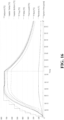
- Figure 16 shows a graph from the second HTHP test.
- the first line above the x-axis shows the pressure inside the vessel. Once the vessel reached ⁇ 725°C at the TF Mid thermocouple, the temperature was maintained for three hours before cooling the system. Once these tests were completed, the pipe connector was disconnected to inspect the sealing surfaces and a new gasket was installed.
- One ATHP and two HTHP tests were performed to confirm sealing and then molten salt was added to the connector. 10 HTHP tests were performed with molten salt covering the seal gasket and in each case the system held pressure overnight, indicating 10 successful tests.
- the salt was transferred from the exemplary pipe connector to the TP, then the systems were disconnected from each other and disassembled. The seal surfaces and threads were cleaned and a new gasket was inserted. After the exemplary pipe connector was prepped, it was reassembled and an ATHP test performed. The exemplary pipe connector held pressure over the weekend, so it was ready for the last two HTHP tests. The exemplary pipe connector was vacuumed to remove the water from the remaining small layer of salt. After the system was dry, the final two HTHP tests were performed. These tests were completed and all testing was deemed successful.
Landscapes
- Engineering & Computer Science (AREA)
- General Engineering & Computer Science (AREA)
- Mechanical Engineering (AREA)
- Quick-Acting Or Multi-Walled Pipe Joints (AREA)
Claims (13)
- Rohrverbinder (100), umfassend
einen zylindrischen Stift (110), der einen Durchgang dort hindurch (114) definiert, wobei der Stift Folgendes umfasst:einen ersten Abschnitt (111), einen zweiten Abschnitt (113) und einen Übergangsabschnitt (112), der sich von dem ersten Abschnitt zu dem zweiten Abschnitt erstreckt, wobei der Übergangsabschnitt eine Vielzahl von ersten Gewinden (117) aufweist, die sich von der Außenfläche des Übergangsabschnittes nach außen erstreckt, und der zweite Abschnitt eine Vielzahl von zweiten Gewinden (122) aufweist, die sich von der Außenfläche des zweiten Abschnittes nach außen erstreckt; undeinen Vorsprung (124), der sich von der Innenfläche des Stiftes, wo der Übergangsabschnitt und der zweite Abschnitt zusammentreffen, nach innen erstreckt, wobei der Vorsprung eine Nut darin definiert;einen zylindrischen Dichtungsring (140), der einen Durchgang dort hindurch (143) definiert und einen ersten Grat (141) und einen zweiten Grat (142) umfasst, die sich von einer Außenfläche des Dichtungsrings nach außen erstrecken, wobei der erste Grat parallel zu dem zweiten Grat ist, wobei der Dichtungsring innerhalb des Stiftes eingesetzt ist, wobei der Vorsprung zwischen dem ersten Grat und dem zweiten Grat positioniert ist, wobei der Durchgang des Dichtungsrings (143) mit dem Durchgang des Stiftes (110) ausgerichtet ist;einen Haltering (150), der innerhalb der Nut positioniert ist, die in dem Vorsprung gebildet ist, und die Außenfläche des Dichtungsrings umgibt;eine zylindrische Box (160) mit einem ersten Ende (163) und einem zweiten Ende (166) und einen Durchgang, der sich dort hindurch (169) erstreckt und eine Vielzahl von Gewinden (168), die sich von der Außenfläche nach außen erstreckt, definierend, wobei die Box eine Nut (164) definiert, die an dem ersten Ende gebildet ist, wobei das erste Ende der Box in den Stift (110) eingesetzt ist, wobei das erste Ende einen Abschnitt des Dichtungsrings umgibt und zwischen dem Dichtungsring (140) und dem Stift (110) positioniert ist, wobei der Durchgang der Box mit dem Durchgang des Dichtungsrings ausgerichtet ist;eine zylindrische Sicherungsmutter (180), die einen Durchgang dort hindurch (183) definiert und eine Vielzahl von Gewinden (186) umfasst, die sich von der Innenfläche der Sicherungsmutter nach innen erstreckt, wobei die Sicherungsmutter um den Stift und die Box positioniert ist und gewindemäßig an die Vielzahl von ersten Gewinden (117) und die Vielzahl von zweiten Gewinden (122) gekoppelt ist; undeine zylindrische Haltemutter (190), die einen Durchgang dort hindurch (193) definiert und eine Vielzahl von Gewinden (194) umfasst, die sich von der Innenfläche der Haltemutter nach innen erstreckt, wobei die Haltemutter um die Box positioniert ist und gewindemäßig an die Vielzahl von Gewinden der Box gekoppelt ist. - Rohrverbinder nach Anspruch 1, wobei der Stift (110) eine Verjüngung an dem distalen Ende des zweiten Abschnittes (113) umfasst, wobei die Verjüngung Selbstausrichtung der Box mit dem Stift bereitstellt, wenn die Box an den Stift gekoppelt ist.
- Rohrverbinder nach Anspruch 1, wobei die Sicherungsmutter (180) abgeschraubt wird, um die Box von dem Stift zu entkoppeln, wobei die Sicherungsmutter eine Kraft auf die Haltemutter bereitstellt, die eine Krafttrennung zwischen dem Stift und der Box bereitstellt, wobei die Gewinde der Sicherungsmutter in einer entgegengesetzten Richtung zu den Gewinden der Haltemutter sind.
- Rohrverbinder nach Anspruch 1, wobei der Dichtungsring (140) einen reduzierten Außendurchmesser entlang des mittleren Abschnittes der Länge des Dichtungsrings umfasst, wobei der reduzierte Außendurchmesser Winkel entlang beider distaler Enden aufweist, die den Haltering (150) kontaktieren und verhindern, dass der Dichtungsring aus seiner Position fällt, wenn der Dichtungsring während Verbindung oder Demontage beginnt, sich zu lösen.
- Rohrverbinder nach Anspruch 4, wobei der Dichtungsring während Demontage der Box von dem Stift immer mit dem Stift gehalten wird.
- Rohrverbinder nach Anspruch 1, wobei der Rohrverbinder für eine Temperatur größer als 700 °C ausgelegt ist.
- Rohrverbinder nach Anspruch 1, wobei der Rohrverbinder eine Dichtungsverbindung zwischen Rohren bei Temperaturen größer als 700 °C aufrechterhält.
- Rohrverbinder nach Anspruch 1, wobei der Rohrverbinder für Drücke ausgelegt ist, die von atmosphärisch bis zu etwa 103421,35 kPa (15.000 psi) reichen.
- Rohrverbinder nach Anspruch 1, wobei der Rohrverbinder eine Dichtungsverbindung zwischen Rohren bei etwa 725 °C und etwa 689,47 kPa (100 psi) aufrechterhält.
- Rohrverbinder nach Anspruch 1, wobei der Rohrverbinder für Verwendung in einem Reaktorsystem, das Salzschmelze involviert, geeignet ist.
- Rohrverbinder nach Anspruch 1, wobei der Rohrverbinder durch eine Wärmehülle oder ein Isoliermaterial umgeben ist, um Temperatur aufrechtzuerhalten.
- Rohrverbinder nach Anspruch 1, wobei der Rohrverbinder geeignet ist, um mit einem hydraulischen Drehmomentschlüssel montiert oder demontiert zu werden.
- Rohrverbinder nach Anspruch 1, wobei der Rohrverbinder geeignet ist, um robotergestützt oder per Fernzugriff getrennt zu werden.
Applications Claiming Priority (2)
| Application Number | Priority Date | Filing Date | Title |
|---|---|---|---|
| US202163160051P | 2021-03-12 | 2021-03-12 | |
| PCT/US2022/019959 WO2022192673A1 (en) | 2021-03-12 | 2022-03-11 | High temperature remotely connected/disconnected pipe connector for molten salt reactors |
Publications (4)
| Publication Number | Publication Date |
|---|---|
| EP4305331A1 EP4305331A1 (de) | 2024-01-17 |
| EP4305331A4 EP4305331A4 (de) | 2024-05-15 |
| EP4305331C0 EP4305331C0 (de) | 2024-11-27 |
| EP4305331B1 true EP4305331B1 (de) | 2024-11-27 |
Family
ID=83228340
Family Applications (1)
| Application Number | Title | Priority Date | Filing Date |
|---|---|---|---|
| EP22768088.1A Active EP4305331B1 (de) | 2021-03-12 | 2022-03-11 | Fernverbundener/getrennter hochtemperaturrohrverbinder für salzschmelzereaktoren |
Country Status (6)
| Country | Link |
|---|---|
| US (1) | US12292138B2 (de) |
| EP (1) | EP4305331B1 (de) |
| CA (1) | CA3211896C (de) |
| ES (1) | ES3000485T3 (de) |
| SA (1) | SA523450669B1 (de) |
| WO (1) | WO2022192673A1 (de) |
Families Citing this family (3)
| Publication number | Priority date | Publication date | Assignee | Title |
|---|---|---|---|---|
| US12562289B2 (en) | 2023-01-20 | 2026-02-24 | Abilene Christian University | Fission product trap for salt pipe and pump shaft seals and methods of use thereof |
| US12590656B2 (en) * | 2023-11-06 | 2026-03-31 | Ho Gun CHUNG | Pipe connection device for repairs |
| US12500006B2 (en) | 2023-12-05 | 2025-12-16 | Natura Resources LLC | Deployment method and systems for molten salt reactors |
Family Cites Families (31)
| Publication number | Priority date | Publication date | Assignee | Title |
|---|---|---|---|---|
| US2291709A (en) | 1940-10-09 | 1942-08-04 | Frederick W Goetze | Gasket construction |
| US2669465A (en) | 1950-08-05 | 1954-02-16 | Dresser Ind | Insulating coupling |
| US2829673A (en) * | 1954-08-24 | 1958-04-08 | Ind Instr Corp | Pipe unions |
| US3471181A (en) * | 1966-10-13 | 1969-10-07 | Imp Eastman Corp | Fitting |
| US3972547A (en) * | 1974-11-21 | 1976-08-03 | Zenzo Ono | Locking and nonseal joint device |
| GB8918093D0 (en) * | 1989-08-08 | 1989-09-20 | Anson Ltd | Improved pipeline couplings |
| JPH05248542A (ja) | 1991-12-30 | 1993-09-24 | Japan Atom Energy Res Inst | メタルガスケットを用いた真空シール構造、真空シール方法、真空シール用メタルガスケットおよびメタルガスケット用真空フランジ |
| GB9404052D0 (en) * | 1994-03-03 | 1994-04-20 | Exploration & Prod Serv | Fluid-tight connecting apparatus |
| DE102006023650A1 (de) * | 2006-05-18 | 2007-11-22 | Eifeler Maschinenbau Gmbh | Rohrverbindung mit einem umgeformten Rohr |
| SE531367C2 (sv) * | 2007-04-05 | 2009-03-10 | Tomas Haakansson | Hydraulkoppling |
| BRPI0721838B1 (pt) * | 2007-06-18 | 2018-06-12 | Weidmann Ltd. | Disposição de junção para uma união roscada de tubos |
| US8857863B1 (en) * | 2010-08-04 | 2014-10-14 | Supreme Service & Specialty Co., Inc. | Method and apparatus for connecting conduit |
| JP5875306B2 (ja) * | 2011-09-22 | 2016-03-02 | 東京エレクトロン株式会社 | 管継手 |
| CN102878109B (zh) | 2012-11-06 | 2014-11-19 | 中国科学院上海应用物理研究所 | 高温熔盐泵轴密封装置 |
| CN102937090B (zh) | 2012-12-03 | 2015-04-08 | 中国科学院上海应用物理研究所 | 一种高温介质泵热屏蔽装置 |
| DE102013018644A1 (de) * | 2013-11-06 | 2015-05-07 | Ludwig Hiss | Vorrichtung zum koaxialen Verbinden zweier Rohrleitungen |
| NO20141497A1 (no) | 2013-12-11 | 2015-06-12 | Stamas Solutions As | Tetningsarrangement for en slagkopling, samt en metallpakning og et mottaksparti for bruk i nevnte tetningsarrangement |
| WO2016003444A1 (en) | 2014-07-01 | 2016-01-07 | Lamons Gasket Company | Electrically isolating, fire-safe sealing element |
| US9522462B2 (en) | 2014-11-14 | 2016-12-20 | Robert Baker | Flange gasket installation apparatus and method |
| EP3338016B1 (de) * | 2015-08-21 | 2022-08-31 | Eaton Intelligent Power Limited | Fluidkopplung und verfahren zur anordnung davon |
| US20170206984A1 (en) | 2016-01-20 | 2017-07-20 | Terrapower, Llc | End cap for nuclear fuel rod having an angled recess and welding thereof |
| US11149883B2 (en) * | 2016-06-24 | 2021-10-19 | Eaton Intelligent Power Limited | Fluid couplings, systems, and methods |
| CN106247043A (zh) * | 2016-08-25 | 2016-12-21 | 嘉兴迈思特管件制造有限公司 | 一种管件密封连接头 |
| US10808871B2 (en) * | 2016-12-13 | 2020-10-20 | Cantex International, Inc. | High pressure flowline union |
| CN108167195B (zh) | 2017-12-27 | 2020-07-31 | 中国科学院上海应用物理研究所 | 一种超高温熔盐轴封泵 |
| US11480273B2 (en) * | 2018-08-09 | 2022-10-25 | Eaton Intelligent Power Limited | Fluid coupling |
| CA3162414A1 (en) | 2019-12-23 | 2021-07-01 | Kent E. Wardle | Molten fuel reactors and orifice ring plates for molten fuel reactors |
| IL295282B2 (en) * | 2020-03-10 | 2025-05-01 | Fujikin Kk | Pipe connector |
| CN212934166U (zh) | 2020-05-07 | 2021-04-09 | 中国科学院上海应用物理研究所 | 一种耐高温隔热管道 |
| CN111508627B (zh) | 2020-05-07 | 2025-03-21 | 中国科学院上海应用物理研究所 | 一种耐高温隔热管道 |
| CN115076479B (zh) | 2022-06-15 | 2023-09-19 | 中国科学院上海应用物理研究所 | 一种高温熔盐环境用法兰自密封装置 |
-
2022
- 2022-03-11 EP EP22768088.1A patent/EP4305331B1/de active Active
- 2022-03-11 CA CA3211896A patent/CA3211896C/en active Active
- 2022-03-11 WO PCT/US2022/019959 patent/WO2022192673A1/en not_active Ceased
- 2022-03-11 US US17/907,505 patent/US12292138B2/en active Active
- 2022-03-11 ES ES22768088T patent/ES3000485T3/es active Active
-
2023
- 2023-09-11 SA SA523450669A patent/SA523450669B1/ar unknown
Also Published As
| Publication number | Publication date |
|---|---|
| WO2022192673A1 (en) | 2022-09-15 |
| SA523450669B1 (ar) | 2024-07-31 |
| US12292138B2 (en) | 2025-05-06 |
| EP4305331A1 (de) | 2024-01-17 |
| CA3211896C (en) | 2024-06-25 |
| EP4305331A4 (de) | 2024-05-15 |
| US20230408002A1 (en) | 2023-12-21 |
| ES3000485T3 (en) | 2025-02-28 |
| EP4305331C0 (de) | 2024-11-27 |
| CA3211896A1 (en) | 2022-09-15 |
Similar Documents
| Publication | Publication Date | Title |
|---|---|---|
| CA3211896C (en) | High temperature remotely connected/disconnected pipe connector for molten salt reactors | |
| US7243409B2 (en) | Weldable conduit method of forming | |
| AU2014366892B2 (en) | Dismantling joint | |
| US5131695A (en) | Coupling with teflon seat | |
| EP0412677B1 (de) | Rohrleitungsverbindung | |
| US11619331B2 (en) | Gasket having interlocked inner diameter seal element | |
| WO1995023908A2 (en) | Fluid-tight connecting apparatus | |
| US5163715A (en) | Lined pipe connection device and method | |
| JPH0689871B2 (ja) | 2本の剛直固定管を接続する密閉型継手 | |
| US10753521B1 (en) | Inner diameter seal gasket | |
| KR101955147B1 (ko) | 압력 변화를 견디기 위한 상호연동 내경 밀봉 요소를 갖는 밀봉 시스템 | |
| CN114484114A (zh) | 一种可偏转任意角度的管道连接器 | |
| EP0183510A1 (de) | Verbindung zum Anflanschen eines Rohres | |
| EP4179284A1 (de) | Dichtungsanordnung | |
| CN115031073B (zh) | 用于贯穿真空腔室的装置及真空系统 | |
| EP4067718B1 (de) | Dichtungsvorrichtung für bohrungen eines wärmetauschers | |
| US12110994B2 (en) | Connector assembly | |
| US11598422B2 (en) | Face seal fitting having a polyimide sealing component for facilitating a face seal | |
| HK40088118A (en) | Connector assembly | |
| HK40088118B (en) | Connector assembly | |
| RU2428616C2 (ru) | Способ изготовления фланцевого соединения | |
| RU2280210C1 (ru) | Разъемное соединение | |
| CN121336336A (zh) | 电缆密封接头 | |
| HK1134533A1 (en) | Banded flexible pipe coupling |
Legal Events
| Date | Code | Title | Description |
|---|---|---|---|
| STAA | Information on the status of an ep patent application or granted ep patent |
Free format text: STATUS: THE INTERNATIONAL PUBLICATION HAS BEEN MADE |
|
| PUAI | Public reference made under article 153(3) epc to a published international application that has entered the european phase |
Free format text: ORIGINAL CODE: 0009012 |
|
| STAA | Information on the status of an ep patent application or granted ep patent |
Free format text: STATUS: REQUEST FOR EXAMINATION WAS MADE |
|
| 17P | Request for examination filed |
Effective date: 20230920 |
|
| AK | Designated contracting states |
Kind code of ref document: A1 Designated state(s): AL AT BE BG CH CY CZ DE DK EE ES FI FR GB GR HR HU IE IS IT LI LT LU LV MC MK MT NL NO PL PT RO RS SE SI SK SM TR |
|
| REG | Reference to a national code |
Ref country code: DE Ref legal event code: R079 Free format text: PREVIOUS MAIN CLASS: F16L0019000000 Ipc: F16L0019020000 Ref country code: DE Ref legal event code: R079 Ref document number: 602022008243 Country of ref document: DE Free format text: PREVIOUS MAIN CLASS: F16L0019000000 Ipc: F16L0019020000 |
|
| A4 | Supplementary search report drawn up and despatched |
Effective date: 20240416 |
|
| RIC1 | Information provided on ipc code assigned before grant |
Ipc: F16J 15/08 20060101ALI20240410BHEP Ipc: F16L 19/028 20060101ALI20240410BHEP Ipc: F16L 19/02 20060101AFI20240410BHEP |
|
| DAV | Request for validation of the european patent (deleted) | ||
| DAX | Request for extension of the european patent (deleted) | ||
| GRAP | Despatch of communication of intention to grant a patent |
Free format text: ORIGINAL CODE: EPIDOSNIGR1 |
|
| STAA | Information on the status of an ep patent application or granted ep patent |
Free format text: STATUS: GRANT OF PATENT IS INTENDED |
|
| INTG | Intention to grant announced |
Effective date: 20240716 |
|
| RIC1 | Information provided on ipc code assigned before grant |
Ipc: F16J 15/08 20060101ALI20240708BHEP Ipc: F16L 19/028 20060101ALI20240708BHEP Ipc: F16L 19/02 20060101AFI20240708BHEP |
|
| GRAS | Grant fee paid |
Free format text: ORIGINAL CODE: EPIDOSNIGR3 |
|
| GRAA | (expected) grant |
Free format text: ORIGINAL CODE: 0009210 |
|
| STAA | Information on the status of an ep patent application or granted ep patent |
Free format text: STATUS: THE PATENT HAS BEEN GRANTED |
|
| AK | Designated contracting states |
Kind code of ref document: B1 Designated state(s): AL AT BE BG CH CY CZ DE DK EE ES FI FR GB GR HR HU IE IS IT LI LT LU LV MC MK MT NL NO PL PT RO RS SE SI SK SM TR |
|
| REG | Reference to a national code |
Ref country code: GB Ref legal event code: FG4D |
|
| REG | Reference to a national code |
Ref country code: CH Ref legal event code: EP |
|
| REG | Reference to a national code |
Ref country code: DE Ref legal event code: R096 Ref document number: 602022008243 Country of ref document: DE |
|
| REG | Reference to a national code |
Ref country code: IE Ref legal event code: FG4D |
|
| U01 | Request for unitary effect filed |
Effective date: 20241224 |
|
| U07 | Unitary effect registered |
Designated state(s): AT BE BG DE DK EE FI FR IT LT LU LV MT NL PT RO SE SI Effective date: 20250114 |
|
| REG | Reference to a national code |
Ref country code: ES Ref legal event code: FG2A Ref document number: 3000485 Country of ref document: ES Kind code of ref document: T3 Effective date: 20250228 |
|
| U20 | Renewal fee for the european patent with unitary effect paid |
Year of fee payment: 4 Effective date: 20250205 |
|
| PG25 | Lapsed in a contracting state [announced via postgrant information from national office to epo] |
Ref country code: IS Free format text: LAPSE BECAUSE OF FAILURE TO SUBMIT A TRANSLATION OF THE DESCRIPTION OR TO PAY THE FEE WITHIN THE PRESCRIBED TIME-LIMIT Effective date: 20250327 Ref country code: HR Free format text: LAPSE BECAUSE OF FAILURE TO SUBMIT A TRANSLATION OF THE DESCRIPTION OR TO PAY THE FEE WITHIN THE PRESCRIBED TIME-LIMIT Effective date: 20241127 |
|
| PG25 | Lapsed in a contracting state [announced via postgrant information from national office to epo] |
Ref country code: NO Free format text: LAPSE BECAUSE OF FAILURE TO SUBMIT A TRANSLATION OF THE DESCRIPTION OR TO PAY THE FEE WITHIN THE PRESCRIBED TIME-LIMIT Effective date: 20250227 |
|
| PG25 | Lapsed in a contracting state [announced via postgrant information from national office to epo] |
Ref country code: GR Free format text: LAPSE BECAUSE OF FAILURE TO SUBMIT A TRANSLATION OF THE DESCRIPTION OR TO PAY THE FEE WITHIN THE PRESCRIBED TIME-LIMIT Effective date: 20250228 |
|
| PG25 | Lapsed in a contracting state [announced via postgrant information from national office to epo] |
Ref country code: PL Free format text: LAPSE BECAUSE OF FAILURE TO SUBMIT A TRANSLATION OF THE DESCRIPTION OR TO PAY THE FEE WITHIN THE PRESCRIBED TIME-LIMIT Effective date: 20241127 |
|
| PG25 | Lapsed in a contracting state [announced via postgrant information from national office to epo] |
Ref country code: RS Free format text: LAPSE BECAUSE OF FAILURE TO SUBMIT A TRANSLATION OF THE DESCRIPTION OR TO PAY THE FEE WITHIN THE PRESCRIBED TIME-LIMIT Effective date: 20250227 |
|
| PG25 | Lapsed in a contracting state [announced via postgrant information from national office to epo] |
Ref country code: SM Free format text: LAPSE BECAUSE OF FAILURE TO SUBMIT A TRANSLATION OF THE DESCRIPTION OR TO PAY THE FEE WITHIN THE PRESCRIBED TIME-LIMIT Effective date: 20241127 |
|
| PGFP | Annual fee paid to national office [announced via postgrant information from national office to epo] |
Ref country code: ES Payment date: 20250410 Year of fee payment: 4 |
|
| PGFP | Annual fee paid to national office [announced via postgrant information from national office to epo] |
Ref country code: CH Payment date: 20250401 Year of fee payment: 4 |
|
| PG25 | Lapsed in a contracting state [announced via postgrant information from national office to epo] |
Ref country code: SK Free format text: LAPSE BECAUSE OF FAILURE TO SUBMIT A TRANSLATION OF THE DESCRIPTION OR TO PAY THE FEE WITHIN THE PRESCRIBED TIME-LIMIT Effective date: 20241127 |
|
| PG25 | Lapsed in a contracting state [announced via postgrant information from national office to epo] |
Ref country code: CZ Free format text: LAPSE BECAUSE OF FAILURE TO SUBMIT A TRANSLATION OF THE DESCRIPTION OR TO PAY THE FEE WITHIN THE PRESCRIBED TIME-LIMIT Effective date: 20241127 |
|
| PLBE | No opposition filed within time limit |
Free format text: ORIGINAL CODE: 0009261 |
|
| STAA | Information on the status of an ep patent application or granted ep patent |
Free format text: STATUS: NO OPPOSITION FILED WITHIN TIME LIMIT |
|
| REG | Reference to a national code |
Ref country code: CH Ref legal event code: L10 Free format text: ST27 STATUS EVENT CODE: U-0-0-L10-L00 (AS PROVIDED BY THE NATIONAL OFFICE) Effective date: 20251008 |
|
| PG25 | Lapsed in a contracting state [announced via postgrant information from national office to epo] |
Ref country code: MC Free format text: LAPSE BECAUSE OF FAILURE TO SUBMIT A TRANSLATION OF THE DESCRIPTION OR TO PAY THE FEE WITHIN THE PRESCRIBED TIME-LIMIT Effective date: 20241127 |
|
| 26N | No opposition filed |
Effective date: 20250828 |
|
| PG25 | Lapsed in a contracting state [announced via postgrant information from national office to epo] |
Ref country code: IE Free format text: LAPSE BECAUSE OF NON-PAYMENT OF DUE FEES Effective date: 20250311 |
|
| U20 | Renewal fee for the european patent with unitary effect paid |
Year of fee payment: 5 Effective date: 20260209 |
|
| REG | Reference to a national code |
Ref country code: CH Ref legal event code: U11 Free format text: ST27 STATUS EVENT CODE: U-0-0-U10-U11 (AS PROVIDED BY THE NATIONAL OFFICE) Effective date: 20260401 |
|
| PGFP | Annual fee paid to national office [announced via postgrant information from national office to epo] |
Ref country code: GB Payment date: 20260106 Year of fee payment: 5 |