EP4304292A1 - Verfahren und vorrichtung zur durchführung eines sldrx-betriebs bei auftreten von slrlf in nr v2x - Google Patents
Verfahren und vorrichtung zur durchführung eines sldrx-betriebs bei auftreten von slrlf in nr v2x Download PDFInfo
- Publication number
- EP4304292A1 EP4304292A1 EP22763647.9A EP22763647A EP4304292A1 EP 4304292 A1 EP4304292 A1 EP 4304292A1 EP 22763647 A EP22763647 A EP 22763647A EP 4304292 A1 EP4304292 A1 EP 4304292A1
- Authority
- EP
- European Patent Office
- Prior art keywords
- drx
- rrc connection
- communication
- timer
- rlf
- Prior art date
- Legal status (The legal status is an assumption and is not a legal conclusion. Google has not performed a legal analysis and makes no representation as to the accuracy of the status listed.)
- Pending
Links
- 238000000034 method Methods 0.000 title claims abstract description 250
- 238000004891 communication Methods 0.000 claims abstract description 150
- 230000005540 biological transmission Effects 0.000 claims description 72
- 230000015654 memory Effects 0.000 claims description 52
- 230000004044 response Effects 0.000 claims description 12
- 238000012544 monitoring process Methods 0.000 claims description 11
- 230000011664 signaling Effects 0.000 claims description 11
- 238000013507 mapping Methods 0.000 claims description 10
- 239000010410 layer Substances 0.000 description 77
- 238000005516 engineering process Methods 0.000 description 27
- 230000006870 function Effects 0.000 description 24
- 125000004122 cyclic group Chemical group 0.000 description 19
- 101000741965 Homo sapiens Inactive tyrosine-protein kinase PRAG1 Proteins 0.000 description 13
- 102100038659 Inactive tyrosine-protein kinase PRAG1 Human genes 0.000 description 13
- 238000013468 resource allocation Methods 0.000 description 12
- 238000012545 processing Methods 0.000 description 10
- 238000013473 artificial intelligence Methods 0.000 description 5
- 230000001174 ascending effect Effects 0.000 description 4
- 230000000694 effects Effects 0.000 description 4
- 230000000737 periodic effect Effects 0.000 description 4
- 238000012546 transfer Methods 0.000 description 4
- 238000001514 detection method Methods 0.000 description 3
- 238000012384 transportation and delivery Methods 0.000 description 3
- 241000700159 Rattus Species 0.000 description 2
- 230000006978 adaptation Effects 0.000 description 2
- 230000007774 longterm Effects 0.000 description 2
- 238000010295 mobile communication Methods 0.000 description 2
- 230000004622 sleep time Effects 0.000 description 2
- 239000004984 smart glass Substances 0.000 description 2
- 230000027311 M phase Effects 0.000 description 1
- 230000004913 activation Effects 0.000 description 1
- 230000003044 adaptive effect Effects 0.000 description 1
- 238000003491 array Methods 0.000 description 1
- 230000003190 augmentative effect Effects 0.000 description 1
- 230000001413 cellular effect Effects 0.000 description 1
- 230000006835 compression Effects 0.000 description 1
- 238000007906 compression Methods 0.000 description 1
- 239000000470 constituent Substances 0.000 description 1
- 238000012937 correction Methods 0.000 description 1
- 239000003814 drug Substances 0.000 description 1
- 238000011156 evaluation Methods 0.000 description 1
- 239000000446 fuel Substances 0.000 description 1
- PCHJSUWPFVWCPO-UHFFFAOYSA-N gold Chemical group [Au] PCHJSUWPFVWCPO-UHFFFAOYSA-N 0.000 description 1
- 238000005286 illumination Methods 0.000 description 1
- 239000002346 layers by function Substances 0.000 description 1
- 238000007726 management method Methods 0.000 description 1
- 239000011159 matrix material Substances 0.000 description 1
- 238000005259 measurement Methods 0.000 description 1
- 230000010363 phase shift Effects 0.000 description 1
- 238000011867 re-evaluation Methods 0.000 description 1
- 230000000630 rising effect Effects 0.000 description 1
- 230000011218 segmentation Effects 0.000 description 1
- 238000010187 selection method Methods 0.000 description 1
- 230000008054 signal transmission Effects 0.000 description 1
- 239000010454 slate Substances 0.000 description 1
- 238000001228 spectrum Methods 0.000 description 1
- 239000011800 void material Substances 0.000 description 1
- 238000005406 washing Methods 0.000 description 1
Images


Classifications
-
- H—ELECTRICITY
- H04—ELECTRIC COMMUNICATION TECHNIQUE
- H04W—WIRELESS COMMUNICATION NETWORKS
- H04W76/00—Connection management
- H04W76/20—Manipulation of established connections
- H04W76/28—Discontinuous transmission [DTX]; Discontinuous reception [DRX]
-
- H—ELECTRICITY
- H04—ELECTRIC COMMUNICATION TECHNIQUE
- H04L—TRANSMISSION OF DIGITAL INFORMATION, e.g. TELEGRAPHIC COMMUNICATION
- H04L1/00—Arrangements for detecting or preventing errors in the information received
- H04L1/12—Arrangements for detecting or preventing errors in the information received by using return channel
- H04L1/16—Arrangements for detecting or preventing errors in the information received by using return channel in which the return channel carries supervisory signals, e.g. repetition request signals
- H04L1/18—Automatic repetition systems, e.g. Van Duuren systems
- H04L1/1812—Hybrid protocols; Hybrid automatic repeat request [HARQ]
-
- H—ELECTRICITY
- H04—ELECTRIC COMMUNICATION TECHNIQUE
- H04L—TRANSMISSION OF DIGITAL INFORMATION, e.g. TELEGRAPHIC COMMUNICATION
- H04L1/00—Arrangements for detecting or preventing errors in the information received
- H04L1/12—Arrangements for detecting or preventing errors in the information received by using return channel
- H04L1/16—Arrangements for detecting or preventing errors in the information received by using return channel in which the return channel carries supervisory signals, e.g. repetition request signals
- H04L1/18—Automatic repetition systems, e.g. Van Duuren systems
- H04L1/1822—Automatic repetition systems, e.g. Van Duuren systems involving configuration of automatic repeat request [ARQ] with parallel processes
-
- H—ELECTRICITY
- H04—ELECTRIC COMMUNICATION TECHNIQUE
- H04L—TRANSMISSION OF DIGITAL INFORMATION, e.g. TELEGRAPHIC COMMUNICATION
- H04L1/00—Arrangements for detecting or preventing errors in the information received
- H04L1/12—Arrangements for detecting or preventing errors in the information received by using return channel
- H04L1/16—Arrangements for detecting or preventing errors in the information received by using return channel in which the return channel carries supervisory signals, e.g. repetition request signals
- H04L1/18—Automatic repetition systems, e.g. Van Duuren systems
- H04L1/1867—Arrangements specially adapted for the transmitter end
- H04L1/1896—ARQ related signaling
-
- H—ELECTRICITY
- H04—ELECTRIC COMMUNICATION TECHNIQUE
- H04L—TRANSMISSION OF DIGITAL INFORMATION, e.g. TELEGRAPHIC COMMUNICATION
- H04L69/00—Network arrangements, protocols or services independent of the application payload and not provided for in the other groups of this subclass
- H04L69/28—Timers or timing mechanisms used in protocols
-
- H—ELECTRICITY
- H04—ELECTRIC COMMUNICATION TECHNIQUE
- H04W—WIRELESS COMMUNICATION NETWORKS
- H04W4/00—Services specially adapted for wireless communication networks; Facilities therefor
- H04W4/30—Services specially adapted for particular environments, situations or purposes
- H04W4/40—Services specially adapted for particular environments, situations or purposes for vehicles, e.g. vehicle-to-pedestrians [V2P]
-
- H—ELECTRICITY
- H04—ELECTRIC COMMUNICATION TECHNIQUE
- H04W—WIRELESS COMMUNICATION NETWORKS
- H04W72/00—Local resource management
- H04W72/20—Control channels or signalling for resource management
- H04W72/25—Control channels or signalling for resource management between terminals via a wireless link, e.g. sidelink
-
- H—ELECTRICITY
- H04—ELECTRIC COMMUNICATION TECHNIQUE
- H04W—WIRELESS COMMUNICATION NETWORKS
- H04W76/00—Connection management
- H04W76/10—Connection setup
- H04W76/14—Direct-mode setup
-
- H—ELECTRICITY
- H04—ELECTRIC COMMUNICATION TECHNIQUE
- H04W—WIRELESS COMMUNICATION NETWORKS
- H04W76/00—Connection management
- H04W76/10—Connection setup
- H04W76/18—Management of setup rejection or failure
-
- H—ELECTRICITY
- H04—ELECTRIC COMMUNICATION TECHNIQUE
- H04W—WIRELESS COMMUNICATION NETWORKS
- H04W92/00—Interfaces specially adapted for wireless communication networks
- H04W92/04—Interfaces between hierarchically different network devices
- H04W92/10—Interfaces between hierarchically different network devices between terminal device and access point, i.e. wireless air interface
-
- H—ELECTRICITY
- H04—ELECTRIC COMMUNICATION TECHNIQUE
- H04W—WIRELESS COMMUNICATION NETWORKS
- H04W92/00—Interfaces specially adapted for wireless communication networks
- H04W92/16—Interfaces between hierarchically similar devices
- H04W92/18—Interfaces between hierarchically similar devices between terminal devices
-
- H—ELECTRICITY
- H04—ELECTRIC COMMUNICATION TECHNIQUE
- H04L—TRANSMISSION OF DIGITAL INFORMATION, e.g. TELEGRAPHIC COMMUNICATION
- H04L67/00—Network arrangements or protocols for supporting network services or applications
- H04L67/01—Protocols
- H04L67/12—Protocols specially adapted for proprietary or special-purpose networking environments, e.g. medical networks, sensor networks, networks in vehicles or remote metering networks
Definitions
- This disclosure relates to a wireless communication system.
- SL communication is a communication scheme in which a direct link is established between User Equipments (UEs) and the UEs exchange voice and data directly with each other without intervention of an evolved Node B (eNB).
- UEs User Equipments
- eNB evolved Node B
- SL communication is under consideration as a solution to the overhead of an eNB caused by rapidly increasing data traffic.
- V2X Vehicle-to-everything refers to a communication technology through which a vehicle exchanges information with another vehicle, a pedestrian, an object having an infrastructure (or infra) established therein, and so on.
- the V2X may be divided into 4 types, such as vehicle-to-vehicle (V2V), vehicle-to-infrastructure (V2I), vehicle-to-network (V2N), and vehicle-to-pedestrian (V2P).
- V2V vehicle-to-vehicle
- V2I vehicle-to-infrastructure
- V2N vehicle-to-network
- V2P vehicle-to-pedestrian
- the V2X communication may be provided via a PC5 interface and/or Uu interface.
- RAT Radio Access Technology
- V2X vehicle-to-everything
- an operation method of a first device (100) in a wireless communication system may include establishing a PC5 radio resource control (RRC) connection with a second device 200; declaring a radio link failure (SL RLF) related to the PC5 RRC connection; and, based on the declared SL RLF, stopping a Uu DRX timer related to the PC5 RRC connection.
- RRC radio resource control
- a UE can efficiently perform sidelink communication.
- a or B may mean “only A”, “only B” or “both A and B.”
- a or B may be interpreted as “A and/or B”.
- A, B, or C may mean “only A”, “only B”, “only C”, or "any combination of A, B, C”.
- a slash (/) or comma used in the present disclosure may mean “and/or”.
- A/B may mean “A and/or B”.
- A/B may mean “only A”, “only B”, or “both A and B”.
- A, B, C may mean “A, B, or C”.
- At least one of A and B may mean “only A”, “only B”, or “both A and B”.
- the expression “at least one of A or B” or “at least one of A and/or B” may be interpreted as "at least one of A and B”.
- At least one of A, B, and C may mean “only A”, “only B”, “only C”, or “any combination of A, B, and C”.
- at least one of A, B, or C or “at least one of A, B, and/or C” may mean “at least one of A, B, and C”.
- a parenthesis used in the present disclosure may mean “for example”.
- control information PDCCH
- PDCCH control information
- a parenthesis used in the present disclosure may mean “for example”.
- control information i.e., PDCCH
- PDCCH control information
- a technical feature described individually in one figure in the present disclosure may be individually implemented, or may be simultaneously implemented.
- a higher layer parameter may be a parameter which is configured, pre-configured or pre-defined for a UE.
- a base station or a network may transmit the higher layer parameter to the UE.
- the higher layer parameter may be transmitted through radio resource control (RRC) signaling or medium access control (MAC) signaling.
- RRC radio resource control
- MAC medium access control
- CDMA code division multiple access
- FDMA frequency division multiple access
- TDMA time division multiple access
- OFDMA orthogonal frequency division multiple access
- SC-FDMA single carrier frequency division multiple access
- the CDMA may be implemented with a radio technology, such as universal terrestrial radio access (UTRA) or CDMA-2000.
- UTRA universal terrestrial radio access
- the TDMA may be implemented with a radio technology, such as global system for mobile communications (GSM)/general packet ratio service (GPRS)/enhanced data rate for GSM evolution (EDGE).
- GSM global system for mobile communications
- GPRS general packet ratio service
- EDGE enhanced data rate for GSM evolution
- the OFDMA may be implemented with a radio technology, such as institute of electrical and electronics engineers (IEEE) 802.11 (Wi-Fi), IEEE 802.16 (WiMAX), IEEE 802.20, evolved UTRA (E-UTRA), and so on.
- IEEE 802.16m is an evolved version of IEEE 802.16e and provides backward compatibility with a system based on the IEEE 802.16e.
- the UTRA is part of a universal mobile telecommunication system (UMTS).
- 3rd generation partnership project (3GPP) long term evolution (LTE) is part of an evolved UMTS (E-UMTS) using the E-UTRA.
- the 3GPP LTE uses the OFDMA in a downlink and uses the SC-FDMA in an uplink.
- LTE-advanced (LTE-A) is an evolution of the LTE.
- 5G NR is a successive technology of LTE-A corresponding to a new Clean-slate type mobile communication system having the characteristics of high performance, low latency, high availability, and so on.
- 5G NR may use resources of all spectrum available for usage including low frequency bands of less than 1GHz, middle frequency bands ranging from 1GHz to 10GHz, high frequency (millimeter waves) of 24GHz or more, and so on.
- FIG. 1 shows a structure of an NR system, based on an embodiment of the present disclosure.
- the embodiment of FIG. 1 may be combined with various embodiments of the present disclosure.
- a next generation-radio access network may include a BS 20 providing a UE 10 with a user plane and control plane protocol termination.
- the BS 20 may include a next generation-Node B (gNB) and/or an evolved-NodeB (eNB).
- the UE 10 may be fixed or mobile and may be referred to as other terms, such as a mobile station (MS), a user terminal (UT), a subscriber station (SS), a mobile terminal (MT), wireless device, and so on.
- the BS may be referred to as a fixed station which communicates with the UE 10 and may be referred to as other terms, such as a base transceiver system (BTS), an access point (AP), and so on.
- BTS base transceiver system
- AP access point
- the embodiment of FIG. 1 exemplifies a case where only the gNB is included.
- the BSs 20 may be connected to one another via Xn interface.
- the BS 20 may be connected to one another via 5th generation (5G) core network (5GC) and NG interface. More specifically, the BSs 20 may be connected to an access and mobility management function (AMF) 30 via NG-C interface, and may be connected to a user plane function (UPF) 30 via NG-U interface.
- 5G 5th generation
- GC 5th generation core network
- AMF access and mobility management function
- UPF user plane function
- Layers of a radio interface protocol between the UE and the network can be classified into a first layer (layer 1, L1), a second layer (layer 2, L2), and a third layer (layer 3, L3) based on the lower three layers of the open system interconnection (OSI) model that is well-known in the communication system.
- a physical (PHY) layer belonging to the first layer provides an information transfer service by using a physical channel
- a radio resource control (RRC) layer belonging to the third layer serves to control a radio resource between the UE and the network.
- the RRC layer exchanges an RRC message between the UE and the BS.
- FIG. 2 shows a radio protocol architecture, based on an embodiment of the present disclosure.
- the embodiment of FIG. 2 may be combined with various embodiments of the present disclosure.
- (a) of FIG. 2 shows a radio protocol stack of a user plane for Uu communication
- (b) of FIG. 2 shows a radio protocol stack of a control plane for Uu communication
- (c) of FIG. 2 shows a radio protocol stack of a user plane for SL communication
- (d) of FIG. 2 shows a radio protocol stack of a control plane for SL communication.
- a physical layer provides an upper layer with an information transfer service through a physical channel.
- the physical layer is connected to a medium access control (MAC) layer which is an upper layer of the physical layer through a transport channel.
- MAC medium access control
- Data is transferred between the MAC layer and the physical layer through the transport channel.
- the transport channel is classified according to how and with what characteristics data is transmitted through a radio interface.
- the physical channel is modulated using an orthogonal frequency division multiplexing (OFDM) scheme, and utilizes time and frequency as a radio resource.
- OFDM orthogonal frequency division multiplexing
- the MAC layer provides services to a radio link control (RLC) layer, which is a higher layer of the MAC layer, via a logical channel.
- RLC radio link control
- the MAC layer provides a function of mapping multiple logical channels to multiple transport channels.
- the MAC layer also provides a function of logical channel multiplexing by mapping multiple logical channels to a single transport channel.
- the MAC layer provides data transfer services over logical channels.
- the RLC layer performs concatenation, segmentation, and reassembly of Radio Link Control Service Data Unit (RLC SDU).
- RLC SDU Radio Link Control Service Data Unit
- TM transparent mode
- UM unacknowledged mode
- AM acknowledged mode
- An AM RLC provides error correction through an automatic repeat request (ARQ).
- a radio resource control (RRC) layer is defined only in the control plane.
- the RRC layer serves to control the logical channel, the transport channel, and the physical channel in association with configuration, reconfiguration and release of RBs.
- the RB is a logical path provided by the first layer (i.e., the physical layer or the PHY layer) and the second layer (i.e., a MAC layer, an RLC layer, a packet data convergence protocol (PDCP) layer, and a service data adaptation protocol (SDAP) layer) for data delivery between the UE and the network.
- the first layer i.e., the physical layer or the PHY layer
- the second layer i.e., a MAC layer, an RLC layer, a packet data convergence protocol (PDCP) layer, and a service data adaptation protocol (SDAP) layer
- Functions of a packet data convergence protocol (PDCP) layer in the user plane include user data delivery, header compression, and ciphering.
- Functions of a PDCP layer in the control plane include control-plane data delivery and ciphering/integrity protection.
- PDCP packet data convergence protocol
- SDAP service data adaptation protocol
- QoS Quality of Service
- DRB data radio bearer
- QFI QoS flow ID
- the configuration of the RB implies a process for specifying a radio protocol layer and channel properties to provide a specific service and for determining respective detailed parameters and operations.
- the RB can be classified into two types, i.e., a signaling RB (SRB) and a data RB (DRB).
- SRB signaling RB
- DRB data RB
- the SRB is used as a path for transmitting an RRC message in the control plane.
- the DRB is used as a path for transmitting user data in the user plane.
- an RRC_CONNECTED state When an RRC connection is established between an RRC layer of the UE and an RRC layer of the E-UTRAN, the UE is in an RRC_CONNECTED state, and, otherwise, the UE may be in an RRC_IDLE state.
- an RRC_INACTIVE state is additionally defined, and a UE being in the RRC_INACTIVE state may maintain its connection with a core network whereas its connection with the BS is released.
- Data is transmitted from the network to the UE through a downlink transport channel.
- the downlink transport channel include a broadcast channel (BCH) for transmitting system information and a downlink-shared channel (SCH) for transmitting user traffic or control messages. Traffic of downlink multicast or broadcast services or the control messages can be transmitted on the downlink-SCH or an additional downlink multicast channel (MCH).
- Data is transmitted from the UE to the network through an uplink transport channel.
- Examples of the uplink transport channel include a random access channel (RACH) for transmitting an initial control message and an uplink SCH for transmitting user traffic or control messages.
- RACH random access channel
- Examples of logical channels belonging to a higher channel of the transport channel and mapped onto the transport channels include a broadcast channel (BCCH), a paging control channel (PCCH), a common control channel (CCCH), a multicast control channel (MCCH), a multicast traffic channel (MTCH), etc.
- BCCH broadcast channel
- PCCH paging control channel
- CCCH common control channel
- MCCH multicast control channel
- MTCH multicast traffic channel
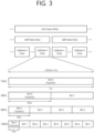
- FIG. 3 shows a structure of a radio frame of an NR, based on an embodiment of the present disclosure.
- the embodiment of FIG. 3 may be combined with various embodiments of the present disclosure.
- a radio frame may be used for performing uplink and downlink transmission.
- a radio frame has a length of 10ms and may be defined to be configured of two half-frames (HFs).
- a half-frame may include five 1ms subframes (SFs).
- a subframe (SF) may be divided into one or more slots, and the number of slots within a subframe may be determined based on subcarrier spacing (SCS).
- SCS subcarrier spacing
- Each slot may include 12 or 14 OFDM(A) symbols according to a cyclic prefix (CP).
- CP cyclic prefix
- each slot may include 14 symbols.
- each slot may include 12 symbols.
- a symbol may include an OFDM symbol (or CP-OFDM symbol) and a Single Carrier-FDMA (SC-FDMA) symbol (or Discrete Fourier Transform-spread-OFDM (DFT-s-OFDM) symbol).
- Table 1 shown below represents an example of a number of symbols per slot (N slot symb ), a number slots per frame (N frame,u slot ), and a number of slots per subframe (N subframe,u slot ) based on an SCS configuration (u), in a case where a normal CP is used.
- Table 2 shows an example of a number of symbols per slot, a number of slots per frame, and a number of slots per subframe based on the SCS, in a case where an extended CP is used.
- OFDM(A) numerologies e.g., SCS, CP length, and so on
- a (absolute time) duration (or section) of a time resource e.g., subframe, slot or TTI
- a time unit (TU) for simplicity
- multiple numerologies or SCSs for supporting diverse 5G services may be supported.
- an SCS is 15kHz
- a wide area of the conventional cellular bands may be supported, and, in case an SCS is 30kHz/60kHz a dense-urban, lower latency, wider carrier bandwidth may be supported.
- the SCS is 60kHz or higher, a bandwidth that is greater than 24.25GHz may be used in order to overcome phase noise.
- An NR frequency band may be defined as two different types of frequency ranges.
- the two different types of frequency ranges may be FR1 and FR2.
- the values of the frequency ranges may be changed (or varied), and, for example, the two different types of frequency ranges may be as shown below in Table 3.
- FR1 may mean a "sub 6GHz range”
- FR2 may mean an "above 6GHz range” and may also be referred to as a millimeter wave (mmW).
- mmW millimeter wave
- FR1 may include a band within a range of 410MHz to 7125MHz. More specifically, FR1 may include a frequency band of 6GHz (or 5850, 5900, 5925 MHz, and so on) and higher. For example, a frequency band of 6GHz (or 5850, 5900, 5925 MHz, and so on) and higher being included in FR1 mat include an unlicensed band. The unlicensed band may be used for diverse purposes, e.g., the unlicensed band for vehicle-specific communication (e.g., automated driving).
- SCS Corresponding frequency range Subcarrier Spacing
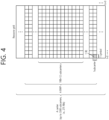
- FIG. 4 shows a structure of a slot of an NR frame, based on an embodiment of the present disclosure.
- the embodiment of FIG. 4 may be combined with various embodiments of the present disclosure.
- a slot includes a plurality of symbols in a time domain.
- one slot may include 14 symbols.
- one slot may include 12 symbols.
- one slot may include 7 symbols.
- one slot may include 6 symbols.
- a carrier includes a plurality of subcarriers in a frequency domain.
- a Resource Block (RB) may be defined as a plurality of consecutive subcarriers (e.g., 12 subcarriers) in the frequency domain.
- a Bandwidth Part (BWP) may be defined as a plurality of consecutive (Physical) Resource Blocks ((P)RBs) in the frequency domain, and the BWP may correspond to one numerology (e.g., SCS, CP length, and so on).
- a carrier may include a maximum of N number BWPs (e.g., 5 BWPs). Data communication may be performed via an activated BWP.
- Each element may be referred to as a Resource Element (RE) within a resource grid and one complex symbol may be mapped to each element.
- RE Resource Element
- bandwidth part BWP
- carrier a bandwidth part (BWP) and a carrier
- the BWP may be a set of consecutive physical resource blocks (PRBs) in a given numerology.
- the PRB may be selected from consecutive sub-sets of common resource blocks (CRBs) for the given numerology on a given carrier
- the BWP may be at least any one of an active BWP, an initial BWP, and/or a default BWP.
- the UE may not monitor downlink radio link quality in a DL BWP other than an active DL BWP on a primary cell (PCell).
- the UE may not receive PDCCH, physical downlink shared channel (PDSCH), or channel state information - reference signal (CSI-RS) (excluding RRM) outside the active DL BWP.
- the UE may not trigger a channel state information (CSI) report for the inactive DL BWP.
- the UE may not transmit physical uplink control channel (PUCCH) or physical uplink shared channel (PUSCH) outside an active UL BWP.
- PUCCH physical uplink control channel
- PUSCH physical uplink shared channel
- the initial BWP may be given as a consecutive RB set for a remaining minimum system information (RMSI) control resource set (CORESET) (configured by physical broadcast channel (PBCH)).
- RMSI remaining minimum system information
- CORESET control resource set
- PBCH physical broadcast channel
- SIB system information block
- the default BWP may be configured by a higher layer.
- an initial value of the default BWP may be an initial DL BWP.
- DCI downlink control information
- the BWP may be defined for SL.
- the same SL BWP may be used in transmission and reception.
- a transmitting UE may transmit a SL channel or a SL signal on a specific BWP
- a receiving UE may receive the SL channel or the SL signal on the specific BWP.
- the SL BWP may be defined separately from a Uu BWP, and the SL BWP may have configuration signaling separate from the Uu BWP.
- the UE may receive a configuration for the SL BWP from the BS/network.
- the UE may receive a configuration for the Uu BWP from the BS/network.
- the SL BWP may be (pre-)configured in a carrier with respect to an out-of-coverage NR V2X UE and an RRC_IDLE UE. For the UE in the RRC_CONNECTED mode, at least one SL BWP may be activated in the carrier.
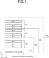
- FIG. 5 shows an example of a BWP, based on an embodiment of the present disclosure.
- the embodiment of FIG. 5 may be combined with various embodiments of the present disclosure. It is assumed in the embodiment of FIG. 5 that the number of BWPs is 3.
- a common resource block may be a carrier resource block numbered from one end of a carrier band to the other end thereof.
- the PRB may be a resource block numbered within each BWP.
- a point A may indicate a common reference point for a resource block grid.
- the BWP may be configured by a point A, an offset N start BWP from the point A, and a bandwidth N size BWP .
- the point A may be an external reference point of a PRB of a carrier in which a subcarrier 0 of all numerologies (e.g., all numerologies supported by a network on that carrier) is aligned.
- the offset may be a PRB interval between a lowest subcarrier and the point A in a given numerology.
- the bandwidth may be the number of PRBs in the given numerology.
- V2X or SL communication will be described.
- a sidelink synchronization signal may include a primary sidelink synchronization signal (PSSS) and a secondary sidelink synchronization signal (SSSS), as a SL-specific sequence.
- PSSS primary sidelink synchronization signal
- SSSS secondary sidelink synchronization signal
- the PSSS may be referred to as a sidelink primary synchronization signal (S-PSS)
- S-SSS sidelink secondary synchronization signal
- S-SSS sidelink secondary synchronization signal
- length-127 M-sequences may be used for the S-PSS
- length-127 gold sequences may be used for the S-SSS.
- a UE may use the S-PSS for initial signal detection and for synchronization acquisition.
- the UE may use the S-PSS and the S-SSS for acquisition of detailed synchronization and for detection of a synchronization signal ID.
- a physical sidelink broadcast channel may be a (broadcast) channel for transmitting default (system) information which must be first known by the UE before SL signal transmission/reception.
- the default information may be information related to SLSS, a duplex mode (DM), a time division duplex (TDD) uplink/downlink (UL/DL) configuration, information related to a resource pool, a type of an application related to the SLSS, a subframe offset, broadcast information, or the like.
- DM duplex mode
- TDD time division duplex
- UL/DL uplink/downlink
- a payload size of the PSBCH may be 56 bits including 24-bit cyclic redundancy check (CRC).
- the S-PSS, the S-SSS, and the PSBCH may be included in a block format (e.g., SL synchronization signal (SS)/PSBCH block, hereinafter, sidelink-synchronization signal block (S-SSB)) supporting periodical transmission.
- the S-SSB may have the same numerology (i.e., SCS and CP length) as a physical sidelink control channel (PSCCH)/physical sidelink shared channel (PSSCH) in a carrier, and a transmission bandwidth may exist within a (pre-)configured sidelink (SL) BWP.
- the S-SSB may have a bandwidth of 11 resource blocks (RBs).
- the PSBCH may exist across 11 RBs.
- a frequency position of the S-SSB may be (pre-)configured. Accordingly, the UE does not have to perform hypothesis detection at frequency to discover the S-SSB in the carrier.
- FIG. 6 shows a procedure of performing V2X or SL communication by a UE based on a transmission mode, based on an embodiment of the present disclosure.
- the transmission mode may be called a mode or a resource allocation mode.
- the transmission mode may be called an LTE transmission mode.
- the transmission mode may be called an NR resource allocation mode.
- (a) of FIG. 6 shows a UE operation related to an LTE transmission mode 1 or an LTE transmission mode 3.
- (a) of FIG. 6 shows a UE operation related to an NR resource allocation mode 1.
- the LTE transmission mode 1 may be applied to general SL communication
- the LTE transmission mode 3 may be applied to V2X communication.
- (b) of FIG. 6 shows a UE operation related to an LTE transmission mode 2 or an LTE transmission mode 4.
- (b) of FIG. 6 shows a UE operation related to an NR resource allocation mode 2.
- a base station may schedule SL resource(s) to be used by a UE for SL transmission.
- a base station may transmit information related to SL resource(s) and/or information related to UL resource(s) to a first UE.
- the UL resource(s) may include PUCCH resource(s) and/or PUSCH resource(s).
- the UL resource(s) may be resource(s) for reporting SL HARQ feedback to the base station.
- the first UE may receive information related to dynamic grant (DG) resource(s) and/or information related to configured grant (CG) resource(s) from the base station.
- the CG resource(s) may include CG type 1 resource(s) or CG type 2 resource(s).
- the DG resource(s) may be resource(s) configured/allocated by the base station to the first UE through a downlink control information (DCI).
- the CG resource(s) may be (periodic) resource(s) configured/allocated by the base station to the first UE through a DCI and/or an RRC message.
- the base station may transmit an RRC message including information related to CG resource(s) to the first UE.
- the base station may transmit an RRC message including information related to CG resource(s) to the first UE, and the base station may transmit a DCI related to activation or release of the CG resource(s) to the first UE.
- the first UE may transmit a PSCCH (e.g., sidelink control information (SCI) or 1 st -stage SCI) to a second UE based on the resource scheduling.
- a PSCCH e.g., sidelink control information (SCI) or 1 st -stage SCI
- the first UE may transmit a PSSCH (e.g., 2 nd -stage SCI, MAC PDU, data, etc.) related to the PSCCH to the second UE.
- the first UE may receive a PSFCH related to the PSCCH/PSSCH from the second UE.
- HARQ feedback information e.g., NACK information or ACK information
- the first UE may transmit/report HARQ feedback information to the base station through the PUCCH or the PUSCH.
- the HARQ feedback information reported to the base station may be information generated by the first UE based on the HARQ feedback information received from the second UE.
- the HARQ feedback information reported to the base station may be information generated by the first UE based on a pre-configured rule.
- the DCI may be a DCI for SL scheduling.
- a format of the DCI may be a DCI format 3_0 or a DCI format 3_1.
- DCI format 3_0 is used for scheduling of NR PSCCH and NR PSSCH in one cell.
- the following information is transmitted by means of the DCI format 3_0 with CRC scrambled by SL-RNTI or SL-CS-RNTI:
- a UE may determine SL transmission resource(s) within SL resource(s) configured by a base station/network or pre-configured SL resource(s).
- the configured SL resource(s) or the pre-configured SL resource(s) may be a resource pool.
- the UE may autonomously select or schedule resource(s) for SL transmission.
- the UE may perform SL communication by autonomously selecting resource(s) within the configured resource pool.
- the UE may autonomously select resource(s) within a selection window by performing a sensing procedure and a resource (re)selection procedure.
- the sensing may be performed in a unit of subchannel(s).
- a first UE which has selected resource(s) from a resource pool by itself may transmit a PSCCH (e.g., sidelink control information (SCI) or 1 st -stage SCI) to a second UE by using the resource(s).
- the first UE may transmit a PSSCH (e.g., 2 nd -stage SCI, MAC PDU, data, etc.) related to the PSCCH to the second UE.
- the first UE may receive a PSFCH related to the PSCCH/PSSCH from the second UE.
- the first UE may transmit a SCI to the second UE through the PSCCH.
- the first UE may transmit two consecutive SCIs (e.g., 2-stage SCI) to the second UE through the PSCCH and/or the PSSCH.
- the second UE may decode two consecutive SCIs (e.g., 2-stage SCI) to receive the PSSCH from the first UE.
- a SCI transmitted through a PSCCH may be referred to as a 1 st SCI, a first SCI, a 1 st -stage SCI or a 1 st -stage SCI format, and a SCI transmitted through a PSSCH may be referred to as a 2 nd SCI, a second SCI, a 2 nd -stage SCI or a 2 nd -stage SCI format.
- the 1 st -stage SCI format may include a SCI format 1-A
- the 2 nd -stage SCI format may include a SCI format 2-A and/or a SCI format 2-B.
- the first UE may receive the PSFCH.
- the first UE and the second UE may determine a PSFCH resource, and the second UE may transmit HARQ feedback to the first UE using the PSFCH resource.
- the first UE may transmit SL HARQ feedback to the base station through the PUCCH and/or the PUSCH.
- a UE can be indicated by an SCI format scheduling a PSSCH reception, in one or more sub-channels from a number of N PSSCH subch sub-channels, to transmit a PSFCH with HARQ-ACK information in response to the PSSCH reception.
- the UE provides HARQ-ACK information that includes ACK or NACK, or only NACK.
- a UE can be provided, by sl-PSFCH-Period-r16, a number of slots in a resource pool for a period of PSFCH transmission occasion resources. If the number is zero, PSFCH transmissions from the UE in the resource pool are disabled.
- a UE may be indicated by higher layers to not transmit a PSFCH in response to a PSSCH reception. If a UE receives a PSSCH in a resource pool and the HARQ feedback enabled/disabled indicator field in an associated SCI format 2-A or a SCI format 2-B has value 1, the UE provides the HARQ-ACK information in a PSFCH transmission in the resource pool.
- the UE transmits the PSFCH in a first slot that includes PSFCH resources and is at least a number of slots, provided by sl- MinTimeGapPSFCH -r 16, of the resource pool after a last slot of the PSSCH reception.
- a UE is provided by sl-PSFCH-RB-Set-r16 a set of M PSFCH PRB,set PRBs in a resource pool for PSFCH transmission in a PRB of the resource pool.
- the PSFCH resources are first indexed according to an ascending order of the PRB index, from the N PSFCH type ⁇ M PSFCH subch,slot PRBs, and then according to an ascending order of the cyclic shift pair index from the N PSFCH CS cyclic shift pairs.
- a UE determines an index of a PSFCH resource for a PSFCH transmission in response to a PSSCH reception as (P ID + M ID ) mod R PSFCH PRB,CS where P ID is a physical layer source ID provided by SCI format 2-A or 2-B scheduling the PSSCH reception, and M ID is the identity of the UE receiving the PSSCH as indicated by higher layers if the UE detects a SCI format 2-A with Cast type indicator field value of "01"; otherwise, M ID is zero.
- a UE determines a m 0 value, for computing a value of cyclic shift ⁇ , from a cyclic shift pair index corresponding to a PSFCH resource index and from N PSFCH CS using Table 5.
- a UE determines a m cs value, for computing a value of cyclic shift ⁇ , as in Table 6 if the UE detects a SCI format 2-A with Cast type indicator field value of "01" or "10", or as in Table 7 if the UE detects a SCI format 2-B or a SCI format 2-A with Cast type indicator field value of "11".
- the UE applies one cyclic shift from a cyclic shift pair to a sequence used for the PSFCH transmission.
- FIG. 7 shows three cast types, based on an embodiment of the present disclosure. The embodiment of FIG. 7 may be combined with various embodiments of the present disclosure.
- FIG. 7(a) shows a broadcast type of SL communication
- FIG. 7(b) shows a unicast type of SL communication
- FIG. 7(c) shows a groupcast type of SL communication.
- unicast type SL communication a UE may perform one-to-one communication with other UEs.
- groupcast type SL communication a UE may perform SL communication with one or more UEs in a group to which it belongs.
- SL groupcast communication may be replaced by SL multicast communication, SL one-to-many communication, and the like.
- the wording "configuration or definition” may be interpreted as being configured (in advance) by a base station or network (e.g., through predefined signaling (e.g., SIB signaling, MAC signaling, RRC signaling).
- a base station or network e.g., through predefined signaling (e.g., SIB signaling, MAC signaling, RRC signaling).
- a may be configured may include "a base station or network (pre)configures/defines or informs the UE of A”.
- the wording "configuration or definition” may be interpreted as being configured or defined in advance by the system.
- “A may be configured” may include "A is configured/defined in advance by the system”.
- the MAC entity may be configured by RRC with a DRX functionality that controls the UE's PDCCH monitoring activity for the MAC entity's C-RNTI, CI-RNTI, CS-RNTI, INT-RNTI, SFI-RNTI, SP-CSI-RNTI, TPC-PUCCH-RNTI, TPC-PUSCH-RNTI, TPC-SRS-RNTI, and AI-RNTI.
- the MAC entity shall also monitor PDCCH according to requirements found in other clauses of this specification.
- the MAC entity may monitor the PDCCH discontinuously using the DRX operation specified in this clause; otherwise the MAC entity shall monitor the PDCCH as specified in TS 38.213 [6].
- NOTE 1 If Sidelink resource allocation mode 1 is configured by RRC, a DRX functionality is not configured.
- RRC controls DRX operation by configuring the following parameters: - drx-onDurationTimer : the duration at the beginning of a DRX cycle; - drx-SlotOffset : the delay before starting the drx-onDurationTimer ; - drx-InactivityTimer : the duration after the PDCCH occasion in which a PDCCH indicates a new UL or DL transmission for the MAC entity; - drx-RetransmissionTimerDL (per DL HARQ process except for the broadcast process): the maximum duration until a DL retransmission is received; - drx-RetransmissionTimerUL (per UL HARQ process): the maximum duration until a grant for UL retransmission is received; - drx-LongCycleStartOffset: the Long DRX cycle and drx-StartOffset which defines the subframe where the Long and Short DRX cycle starts; - drx-
- NR V2X in Release 16 did not support power-saving operation of devices, and Release 17 NR V2X will support power-saving operation of devices (e.g., power-saving devices).
- an SL DRX configuration (SL DRX cycle, SL DRX on-duration, SL DRX off-duration, timer to support SL DRX operation, etc.) to be used by a P-UE (power saving UE) may need to be defined.
- the operation of transmitting and receiving UEs during the on-duration (when sidelink reception/transmission can be performed) and off-duration (when they operate in sleep mode) may need to be defined.
- the embodiment(s) of the present disclosure propose a method of operating the SL DRX when a UE declares a radio link failure (SL RLF).
- SL RLF radio link failure
- the transmitting UE may stop the operating Uu DRX hybrid automatic repeat request (HARQ) RTT TimerSL/Uu DRX retransmission TimerSL and stop monitoring for PDCCHs transmitted by a base station.
- HARQ hybrid automatic repeat request
- the transmitting UE may not start the timer upon declaring the SL RLF.
- Table 12 shows the conditions under which a UE declares an SL RLF, according to one embodiment of the present disclosure.
- a UE may declare an SL RLF based on an indication from an SL RLC layer, that the number of retransmissions for a specific destination has reached the maximum number of retransmissions.
- a UE may declare an SL RLF based on the expiration of a T400 related to a specific destination.
- a UE may declare an SL RLF based on an indication from an SL MAC layer, that the number of consecutive HARQ DTXs related to a specific destination has reached the maximum number of consecutive HARQ DTXs.
- a UE may declare an SL RLF based on an integrity check failure indication for SL-SRB2 or SL-SRB3 for a specific destination from an SL PDCP layer.
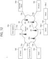
- FIG. 8 shows an example of a declaration of an RLF and an example of stopping Uu DRX TimerSL operation based on the RLF, according to one embodiment of the present disclosure.
- the embodiment of FIG. 8 may be combined with various embodiments of the present disclosure.
- a transmitting UE and a receiving UE may establish a PC5 RRC connection between each other.
- the transmitting UE may perform an SL transmission to the receiving UE.
- the SL transmission may be a transmission related to a first HARQ process ID.
- the receiving UE may transmit to the transmitting UE an SL HARQ NACK for the SL transmission.
- the receiving UE may fail to decode the SL transmission.
- the SL HARQ NACK may be transmitted to the transmitting UE based on the decoding failure.
- the transmitting UE may request retransmission resources for retransmission related to the first HARQ process ID from a base station based on the SL HARQ NACK. And, the transmitting UE may start a Uu DRX TimerSL to receive the retransmission resource.
- the Uu DRX TimerSL may be a timer related to the first HARQ process ID (or, for example, the PC5 RRC connection), i.e., the Uu DRX TimerSL may be a timer for SL communication only related to the first HARQ process ID, i.e., the Uu DRX TimerSL may not be related to a second HARQ process ID different from the first HARQ process ID.
- the transmitting UE may declare an SL RLF related to the first HARQ process ID (or, for example, the PC5 RRC connection), based on conditions being met according to various embodiments of the present disclosure.
- the transmitting UE may stop the Uu DRX TimerSL related to the first HARQ process ID (or, for example, the PC5 RRC connection) based on the declaration of the SL RLF, i.e., the transmitting UE may stop monitoring the DCI (or, for example, PDCCH) related to the requested retransmission resource.
- the transmitting UE may transmit SL UE information (e.g., SidelinkUEInformation) to the base station.
- the SL UE information may include information according to various embodiments of the present disclosure.
- the SL UE information may include information related to the first HARQ process ID and/or information related to a source/destination identifier pair of the transmitting UE and the receiving UE.
- the base station may stop scheduling retransmissions related to the first HARQ process ID (or, for example, the PC5 RRC connection) based on the SL UE information; and/or, the base station may release configurations related to the first HARQ process ID.
- the configurations may include an SL DRB configuration related to the first HARQ process ID or an SL DRX configuration related to the first HARQ process ID.
- a transmitting UE may only stop a Uu DRX timerSL related to a HARQ process ID that is related to (or has a linkage to) an SL process (or SL process ID) operating on the PC5 RRC connection (or PC5 unicast link) on which the SL RLF is declared.
- the Uu DRX HARQ RTT TimerSL or Uu DRX Retransmission TimerSL may be timers for monitoring SL mode 1 DCI.
- Uu DRX HARQ RTT TimerSL and Uu DRX retransmission timerSL may be operated on a per HARQ process ID basis. That is, for example, in the event of an SL RLF, it may not be allowed, for a Uu DRX timerSL (e.g., Uu DRX HARQ RTT TimerSL, or Uu DRX Retransmission TimerSL) operating on a different HARQ process ID with the HARQ process ID related to (or linked to) a specific SL process (or SL process ID) operating on the PC5 unicast link where the SL RLF occurred, to be stopped.
- a Uu DRX timerSL e.g., Uu DRX HARQ RTT TimerSL, or Uu DRX Retransmission TimerSL
- a transmitting UE may include the following information in SidelinkUEInformation (or, SL UE information) to be forwarded to a base station when an SL RLF is declared under the conditions referred to in the present disclosure.
- an information element (IE) of the SL UE information may include at least one of the source/destination ID pair information (or, PC5 link ID) from which the SL RLF occurred, the SL process ID operating on the PC5 RRC connection (or, PC5 unicast link) on which the SL RLF was declared, and/or the HARQ process ID related to (or linked to) the SL process ID operating on the PC5 RRC connection (or, PC5 unicast link) on which the SL RLF was declared.
- Table 13 shows HARQ process IDs, according to one embodiment of the present disclosure.
- a sidelink grant on the PDCCH if a sidelink grant has been received on the PDCCH for the MAC entity's SLCS-RNTI: 2> if PDCCH contents indicate retransmission(s) for the identifed HARQ process ID that has been set for an activated configured sidelink grant identified by sl-ConfigIndexCG: 3> use the received sidelink grant to determine PSCCH duration(s) and PSSCH duration(s) for one or more retransmissions of a single MAC PDU according to clause 8.1.2 of TS 38.214 [7].
- Tables 14 through 16 show SL process IDs, according to one embodiment of the present disclosure.
- Sidelink transmission information included in a SCI for a SL-SCH transmission as specified in clause 8.3 and 8.4 of TS 38.212 [9] consists of Sidelink HARQ information including NDI, RV, Sidelink process ID, HARQ feedback enabled/disabled indicator, Sidelink identification information including cast type indicator, Source Layer-1 ID and Destination Layer-1 ID, and Sidelink other information including CSI request, a priority, a communication range requirement and Zone ID.
- the MAC entity includes at most one Sidelink HARQ entity for transmission on SL-SCH, which maintains a number of parallel Sidelink processes.
- the maximum number of transmitting Sidelink processes associated with the Sidelink HARQ Entity is 16.
- a sidelink process may be configured for transmissions of multiple MAC PDUs. For transmissions of multiple MAC PDUs with Sidelink resource allocation mode 2, the maximum number of transmitting Sidelink processes associated with the Sidelink HARQ Entity is 4.
- a delivered sidelink grant and its associated Sidelink transmission information are associated with a Sidelink process. Each Sidelink process supports one TB.
- the Sidelink HARQ Entity shall: 1> if the MAC entity determines that the sidelink grant is used for initial transmission as specified in clause 5.22.1.1; or 1> if the sidelink grant is a configured sidelink grant and no MAC PDU has been obtained in a sl-PeriodCG of the configured sidelink grant: NOTE 1: Void. 2> (re-)associate a Sidelink process to this grant, and for the associated Sidelink process: NOTE lA: The Sidelink HARQ Entity will associate the selected sidelink grant to the Sidelink process determined by the MAC entity.
- 3> obtain the MAC PDU to transmit from the Multiplexing and assembly entity, if any; 3> if a MAC PDU to transmit has been obtained: 4> if a HARQ Process ID has been set for the sidelink grant: 5> (re-)associate the HARQ Process ID corresponding to the sidelink grant to the Sidelink process; NOTE 1a: There is one-to-one mapping between a HARQ Process ID and a Sidelink process in the MAC entity configured with Sidelink resource allocation mode 1.
- 4> determines Sidelink transmission information of the TB for the source and destination pair of the MAC PDU as follows: 5> set the Source Layer-1 ID to the 8 LSB of the Source Layer-2 ID of the MAC PDU; 5> set the Destination Layer-1 ID to the 16 LSB of the Destination Layer-2 ID of the MAC PDU; 5> (re-)associate the Sidelink process to a Sidelink process ID; NOTE lb: How UE determine Sidelink process ID in SCI is left to UE implementation for NR sidelink.
- the number of Receiving Sidelink processes associated with the Sidelink HARQ Entity is defined in TS 38.306 [5].
- the Sidelink HARQ Entity shall: 1> for each SCI valid for this PSSCH duration: 2> if the NDI has been toggled compared to the value of the previous received transmission corresponding to the Sidelink identification information and the Sidelink process ID of the SCI or this is the very first received transmission for the pair of the Sidelink identification information and the Sidelink process ID of the SCI: 3> if there is a Sidelink process associated with the Sidelink identification information and the Sidelink process ID of the SCI: 4> consider the Sidelink process as unoccupied; 4> flush the soft buffer for the Sidelink process.
- 3> allocate the TB received from the physical layer and the associated Sidelink identification information and Sidelink process ID to an unoccupied Sidelink process; 3> associate the Sidelink process with the Sidelink identification information and the Sidelink process ID of this SCI and consider this transmission to be a new transmission.
- a single sidelink process can only be (re-)associated to a single combination of Sidelink identification information and Sidelink process ID at a time and a single combination of Sidelink identification information and Sidelink process ID can only be (re-)associated to a single sidelink process at a time.
- a base station based on information contained in the SL UE information (e.g., sidelinkUEInformation) transmitted by a transmitting UE, may determine a Uu DRX timerSL (for SL mode 1 DCI monitor purposes) at which the transmitting UE will declare and stop an SL RLF (e.g., Uu DRX HARQ RTT TimerSL, or, Uu DRX Retransmission TimerSL), and stop the retransmission scheduling operation of the SL transmission related to (the SL RLF, or, the SL RLF-related HARQ process ID), or, terminate the SL data radio bearer (DRB) configuration and associated Uu DRX timerSL configuration related to (the SL RLF, or, the SL RLF-related HARQ process ID).
- SL RLF e.g., Uu DRX HARQ RTT TimerSL, or, Uu DRX Retransmission TimerSL
- DRB SL data radio bearer
- FIG. 9 shows an example of stopping Uu DRX TimerSL operation based on RLF and PC5 RRC connections, according to one embodiment of the present disclosure.
- the embodiment of FIG. 9 may be combined with various embodiments of the present disclosure.
- a transmitting UE may establish a PC5 RRC connection with each of a first receiving UE and a second receiving UE.
- the PC5 RRC connection between the transmitting UE and the first receiving UE may be a first PC5 RRC connection
- the PC5 RRC connection between the transmitting UE and the second receiving UE may be a second PC5 RRC connection.
- the transmitting UE may perform an SL transmission to the first receiving UE and the second receiving UE.
- the SL transmission may be a transmission related to a first HARQ process ID and a second HARQ process ID, respectively.
- the first receiving UE and the second receiving UE may each transmit an SL HARQ NACK for the SL transmission to the transmitting UE.
- the first receiving UE and the second receiving UE may fail to decode the SL transmission.
- the respective SL HARQ NACKs may be transmitted to the transmitting UE based on the decoding failure.
- the transmitting UE may request retransmission resources for retransmission related to the first HARQ process ID and retransmission resources for retransmission related to the second HARQ process ID from a base station based on the respective SL HARQ NACK. And, the transmitting UE may start a first Uu DRX TimerSL and ad second Uu DRX TimerSL to receive the retransmission resources.
- the first Uu DRX TimerSL may be a timer related to the first HARQ process ID
- the second Uu DRX TimerSL may be a timer related to the second HARQ process ID.
- the transmitting UE may declare an SL RLF related to the second HARQ process ID, based on conditions being met according to various embodiments of the present disclosure.
- the transmitting UE may stop the second Uu DRX TimerSL related to the second HARQ process ID, based on the declaration of the SL RLF, i.e., the transmitting UE may stop monitoring the DCI (or, PDCCH) related to the retransmission resources for retransmission related to the second HARQ process ID.
- the transmitting UE may transmit SL UE information (e.g., SidelinkUEInformation) to the base station.
- the SL UE information may include information according to various embodiments of the present disclosure.
- the SL UE information may include information related to the second HARQ process ID and/or information related to a source/destination ID pair of the transmitting UE and the second receiving UE, and the like.
- the base station may stop scheduling retransmissions related to the second HARQ process ID based on the SL UE information; and/or the base station may release configurations related to the second HARQ process ID.
- the configurations may include an SL DRB configuration related to the second HARQ process ID or an SL DRX configuration related to the second HARQ process ID.
- the base station may still continue to perform scheduling of retransmissions related to the first HARQ process ID, and may maintain configurations related to the first HARQ process ID.
- the base station may transmit to the transmitting UE information related to a retransmission resource for retransmission related to the second HARQ process ID.
- the information related to the retransmission resource may be transmitted via DCI (or, PDCCH).
- the transmitting UE may, based on the retransmission resource, perform a retransmission related to the first HARQ process ID to the first receiving UE.
- a plurality of SL processes may be performed based on the PC5 RRC connection.
- a first SL process may be related to a first SL process ID
- a second SL process may be related to a second SL process ID.
- the HARQ process ID and the SL process ID may have a one-to-one mapping relationship, i.e., according to an embodiment of the present disclosure, when there are a plurality of SL processes performed between a transmitting UE and a receiving UE, an SL RLF may be declared for only some of the plurality of SL processes.
- the operation related to the second SL process may be maintained. Also, for example, based on the SL RLF, the Uu DRX TimerSL related to the first HARQ process ID related to the first SL process ID may be stopped, while the Uu DRX TimerSL related to the second SL process ID may continue to operate despite the SL RLF.
- a receiving UE may declare an SL RLF if the following conditions are met. For example, based on the SL RLF, the receiving UE may stop the operating SL DRX on-duration timer, SL DRX inactivity timer, SL DRX HARQ RTT timer, and SL DRX retransmission timer, and may stop monitoring the SL signals, SL channels, etc. (e.g., PSCCH, PSSCH, SL-SSB, etc.) transmitted by a transmitting UE. Alternatively, for example, the receiving UE may stop transmitting PSFCH, SL-SSB based on the SL RLF.
- the receiving UE may stop transmitting PSFCH, SL-SSB based on the SL RLF.
- the receiving UE may not start the timers upon the occurrence of the SL RLF.
- Table 17 indicates the conditions under which a UE declares an SL RLF, according to one embodiment of the present disclosure.
- a UE may declare an SL RLF based on an indication from the SL RLC layer that the number of retransmissions for a specific destination has reached the maximum number of retransmissions.
- a UE may declare an SL RLF based on the expiration of a T400 related to a specific destination.
- a UE may declare an SL RLF based on an indication from an SL MAC layer that the number of consecutive HARQ DTXs related to a specific destination has reached the maximum number of consecutive HARQ DTXs.
- a UE may declare an SL RLF based on an integrity check failure indication for SL-SRB2 or SL-SRB3 for a specific destination from an SL PDCP layer.
- a receiving UE may only stop an SL DRX timer (e.g., SL DRX on-duration timer, SL DRX inactivity timer) related to a PC5 RRC connection (or PC5 unicast link) for which an SL RLF has been declared.
- an SL DRX timer e.g., SL DRX on-duration timer, SL DRX inactivity timer
- a receiving UE may not be allowed to stop an SL DRX timer (e.g., SL DRX on-duration timer, SL DRX inactivity timer) that is operating on a PC5 RRC link other than the PC5 unicast link on which the SL RLF occurred.
- an SL DRX timer e.g., SL DRX on-duration timer, SL DRX inactivity timer
- a receiving UE may only stop SL DRX timers (e.g., SL DRX on-duration timer, SL DRX inactivity timer, SL DRX HARQ RTT timer, SL DRX retransmission timer) that are related to (or have a link to) a specific SL process (or SL process ID) operating on a PC5 RRC connection (or PC5 unicast link) for which an SL RLF has been declared.
- SL DRX timers e.g., SL DRX on-duration timer, SL DRX inactivity timer, SL DRX HARQ RTT timer, SL DRX retransmission timer
- it may not be allowed to stop SL DRX timers that are not related to a specific SL process on the receiving UE.
- an SL DRX timer (e.g., SL DRX HARQ RTT timer, SL DRX retransmission timer) may be operated on a per SL process ID basis, and upon the occurrence of an SL RLF, it may not be allowed, for an SL DRX timer (e.g., SL DRX HARQ RTT timer, SL DRX retransmission timer) operating on any SL process except the specific SL process (or, SL process ID) operating on the PC5 unicast link where the SL RLF occurred, to be stopped.
- SL DRX timer e.g., SL DRX HARQ RTT timer, SL DRX retransmission timer
- a receiving UE may include the following information in SL UE information (e.g., SidelinkUEInformation) to be transmitted to a base station when an SL RLF is declared under the conditions mentioned in the present disclosure.
- SL UE information e.g., SidelinkUEInformation
- an IE of the SL UE information may include at least one of source/destination ID pair information (or PC5 link ID) from which the SL RLF occurred, an SL process ID operating on the PC5 RRC connection (or PC5 unicast link) that declared the SL RLF, and/or a HARQ process ID related to (or having a link to) the SL process ID operating on the PC5 RRC connection (or PC5 unicast link) that declared the SL RLF.
- a base station may determine an SL DRX timer (e.g., SL DRX on-duration timer, SL DRX inactivity timer, SL DRX HARQ RTT timer, SL DRX retransmission timer) at which the receiving UE may declare and stop SL RLF per PC5 unicast link (or, per PC5 RRC connection, or, "per SL process ID per PC5 RRC connection (or, PC5 unicast link)”), and release SL DRX configuration related to (the SL RLF, or, a HARQ process ID related to the SL RLF) and SL DRX timer configuration.
- SL DRX timer e.g., SL DRX on-duration timer, SL DRX inactivity timer, SL DRX HARQ RTT timer, SL DRX retransmission timer
- the receiving UE may declare and stop SL RLF per PC5 unicast link (or, per
- the SL DRX configurations referred to in the present disclosure may include at least one or more of the parameters in Table 18.
- Table 18 shows SL DRX configurations, according to one embodiment of the present disclosure.
- ⁇ Sidelink DRX configurations ⁇ SL drx-onDurationTimer : the duration at the beginning of a DRX Cycle; ⁇ SL drx-SlotOffset: the delay before starting the drx-onDurationTimer; ⁇ SL drx-InactivityTimer: the duration after the PSCCH occasion in which a PSCCH indicates a new SL transmission for the MAC entity; ⁇ SL drx-RetransmissionTimer (per Sidelink process): the maximum duration until a retransmission is received; ⁇ SL drx-HARQ-RTT-Timer (per Sidelink process): the minimum duration before PSCCH (Sideink Control Information ) & PSSCH for SL HARQ retransmission is expected by the
- SL DRX on-duration timer Indicates the period of time during which a UE performing SL DRX operation should operate as the default active time to receive PSCCH/PSSCH from other UE.
- SL DRX inactivity timer may represent an interval that extends an SL DRX on-duration interval, which is an interval during which a UE performing SL DRX operation must operate as active by default to receive PSCCH/PSSCH from other UE. That is, an SL DRX on-duration timer may be extended by the SL DRX inactivity timer interval. Furthermore, when a UE receives a new packet (new PSSCH transmission) from other UE, the UE may extend the SL DRX on-duration timer by starting an SL DRX inactivity timer.
- SL DRX HARQ RTT timer may indicate an interval during which a UE performing SL DRX operation may operate in sleep mode until it receives a retransmission packet (or PSSCH assignment) from other UE. That is, if a UE starts the SL DRX HARQ RTT timer, the UE may determine that other UE will not transmit a sidelink retransmission packet to it until the SL DRX HARQ RTT timer expires and may operate in sleep mode during that timer.
- SL DRX retransmission timer may indicate an interval of time during which a UE performing SL DRX operation is active to receive retransmission packets (or PSSCH assignments) transmitted by other UE. During this timer period, a UE may monitor a reception of retransmission sidelink packets (or PSSCH allocations) transmitted by other UE.
- Uu DRX HARQ RTT TimerSL indicates an interval during which a UE performing Uu DRX operation does not need to monitor DCI (PDCCH) for SL mode 1 operation transmitted by a base station. While this timer is running, a UE may not need to monitor a PDCCH for SL mode 1 operation.
- PDCCH DCI
- Uu DRX retransmission TimerSL indicates an interval during which a UE performing Uu DRX operation monitors DCI (PDCCH) for SL mode 1 operation transmitted by a base station. While this timer is running, a UE may monitor a PDCCH for SL mode 1 operation transmitted by a base station.
- PDCCH DCI
- timers SL DRX On-Duration Timer, SL DRX Inactive Timer, SL HARQ RTT Timer, SL DRX Retransmission Timer, Uu DRX HARQ RTT TimerSL, Uu DRX Retransmission TimerSL, etc.
- timers that perform the same/similar functions based on what is described in each timer can be considered the same/similar timer regardless of the name.
- the proposals in this disclosure may be extended to parameters (and timers) included in default/common SL DRX configurations or default/common SL DRX patterns or default/common SL DRX configurations, as well as parameters (and timers) included in UE pair specific SL DRX configurations or UE pair specific SL DRX patterns or UE pair specific SL DRX configurations.
- an on-duration term referred to in the present disclosure may be extended to an active time interval, and an off-duration term may be extended to a sleep time interval.
- an active time may refer to a period of time when a UE is operating in a wake up state (RF module is on) to receive/transmit radio signals.
- sleep time may refer to an interval during which a UE operates in a sleep mode state (RF module is off) to conserve power.
- a sleep period does not imply that a transmitting UE is obligated to operate in sleep mode, i.e., the UE may be allowed to operate in active time for a short period of time to perform a sensing operation/transmission operation if necessary, even during a sleep period.
- the related parameters may be configured specifically (or differently or independently) depending on the resource pool, congestion level, service priority (and/or type), requirements (e.g., latency, reliability), traffic type (e.g., (aperiodic) generation), SL transport resource allocation mode (Mode 1, Mode 2), etc.
- whether to apply the proposals of the present disclosure may be configured specifically (and/or, independently and/or differently) for at least one of a resource pool, service/packet type (and/or priority), QoS requirement (e.g., URLLC/EMBB traffic, reliability, latency), cast type (e.g., unicast, groupcast, broadcast), (resource pool) congestion level (e.g., CBR), SL HARQ feedback mode (e.g., NACK only feedback, ACK/NACK feedback), a HARQ feedback enabled MAC PDU (and/or a HARQ feedback disabled MAC PDU) transmission case, whether PUCCH based SL HARQ feedback reporting operation is configured, a case where pre-emption (and/or re-evaluation) (or, -based resource reselection) is performed, (L2 or L1) (source and/or destination) ID, PC5 RRC connection/link, a case where an SL DRX is performed,
- QoS requirement e.g.
- the term active time as used in the present disclosure may refer to a predefined amount of time for a UE to receive sidelink signaling or sidelink data from another UE, or a period of time, or a specific timer (SL DRX retransmission timer, SL DRX inactivity timer, or a timer to ensure a receiving UE to operate as an active time in DRX operation) time, during which a UE is active.
- SL DRX retransmission timer SL DRX inactivity timer
- timer to ensure a receiving UE to operate as an active time in DRX operation
- the transmitting UE and a base station can distinguish a specific SL process for which an SL RLF has occurred among the plurality of SL processes. Therefore, the transmitting UE can continue to operate the SL processes for which the SL RLF has not occurred, and can stop only the Uu DRX TimerSL corresponding to the SL RLF, thereby maintaining efficient SL communication and generating a power-saving effect of the DRX operation.
- the base station can stop the retransmission scheduling and cancel the SL DRB and SL DRX configurations related to the HARQ process corresponding to the SL RLF while maintaining the operation related to the SL process in which the SL RLF does not occur, so that the power-saving effect of the DRX operation can be generated while maintaining efficient Mode 1 SL communication.
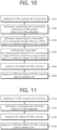
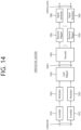
- FIG. 10 shows a procedure for a first device to perform wireless communication, according to one embodiment of the present disclosure.
- the embodiment of FIG. 10 may be combined with various embodiments of the present disclosure.
- a first device may establish PC5 radio resource control, RRC, connection with a second device.
- the first device may perform sidelink, SL, communication with the second device performing an SL discontinuous reception, DRX, operation based on an SL DRX configuration.
- the first device may perform a resource request, to a base station, for the SL communication through a physical uplink control channel, PUCCH, or a physical uplink shared channel, PUSCH, based on a Uu DRX timer related to the PC5 RRC connection.
- the first device may monitor, from the base station, downlink control information, DCI, including resource information for the SL communication, through a physical downlink control channel, PDCCH, as a response to the resource request, based on the Uu DRX timer related to the PC5 RRC connection.
- the first device may declare SL radio link failure, RLF, related to the PC5 RRC connection.
- the first device may stop the Uu DRX timer related to the PC5 RRC connection, based on the declared SL RLF.
- stop of a Uu DRX timer not related to the PC5 RRC connection may be not allowed, based on the declared SL RLF.
- the first device may stop monitoring for the DCI related to the PC5 RRC connection.
- stop of monitoring for DCI not related to the PC5 RRC connection may be not allowed.
- the first device may transmit, to the base station, SL UE information related to the SL RLF.
- the SL UE information may include at least one of a hybrid automatic repeat request, HARQ, process identifier, ID, related to the PC5 RRC connection, a source/destination ID pair related to the PC5 RRC connection, or an SL process ID related to the PC5 RRC connection.
- a retransmission scheduling operation related to the PC5 RRC connection may be stopped by the base station, based on the SL UE information.
- an SL data radio bearer, DRB, configuration related to the PC5 RRC connection or a configuration related to the Uu DRX timer related to the PC5 RRC connection may be released by the base station, based on the SL UE information.
- the SL RLF may be declared based on at least one of: i) a number of retransmissions for a destination of the PC5 RRC connection reaching a maximum retransmission number; ii) T400 for the destination of the PC5 RRC connection being expired; iii) a number of consecutive occurrences of HARQ discontinuous transmission, DTX, for the destination of the PC5 RRC connection reaching a maximum number of consecutive occurrences of HARQ DTX; or iv) a failure of an integrity check for a signaling radio bearer, SRB, for the PC5 RRC connection.
- SRB signaling radio bearer
- the Uu DRX timer may include a Uu DRX HARQ round trip time, RTT, TimerSL or a Uu DRX Retransmission TimerSL.
- the Uu DRX timer may be related to a HARQ process ID related to SL data transmitted through the SL communication.
- a HARQ process ID related to the PC5 RRC connection may be determined based on a current slot at which the SL communication is performed.
- an SL process related to the PC5 RRC connection and a HARQ process ID related to the PC5 RRC connection may have a one to one mapping relationship.
- an SL process ID related to the SL process and the HARQ process ID may have a one to one mapping relationship.
- a processor 102 of a first device 100 may establish PC5 radio resource control, RRC, connection with a second device 200. And, the processor 102 of the first device 100 may control a transceiver 106 to perform sidelink, SL, communication with the second device 200 performing an SL discontinuous reception, DRX, operation based on an SL DRX configuration.
- RRC PC5 radio resource control
- DRX SL discontinuous reception
- the processor 102 of the first device 100 may control the transceiver 106 to perform a resource request, to a base station 300, for the SL communication through a physical uplink control channel, PUCCH, or a physical uplink shared channel, PUSCH, based on a Uu DRX timer related to the PC5 RRC connection. And, the processor 102 of the first device 100 may monitor, from the base station 300, downlink control information, DCI, including resource information for the SL communication, through a physical downlink control channel, PDCCH, as a response to the resource request, based on the Uu DRX timer related to the PC5 RRC connection.
- DCI downlink control information
- PDCCH physical downlink control channel
- the processor 102 of the first device 100 may declare SL radio link failure, RLF, related to the PC5 RRC connection. And, the processor 102 of the first device 100 may stop the Uu DRX timer related to the PC5 RRC connection, based on the declared SL RLF.
- a first device for performing wireless communication may comprise: one or more memories storing instructions; one or more transceivers; and one or more processors connected to the one or more memories and the one or more transceivers.
- the one or more processors may execute the instructions to: establish PC5 radio resource control, RRC, connection with a second device; perform sidelink, SL, communication with the second device performing an SL discontinuous reception, DRX, operation based on an SL DRX configuration; perform a resource request, to a base station, for the SL communication through a physical uplink control channel, PUCCH, or a physical uplink shared channel, PUSCH, based on a Uu DRX timer related to the PC5 RRC connection; monitor, from the base station, downlink control information, DCI, including resource information for the SL communication, through a physical downlink control channel, PDCCH, as a response to the resource request, based on the Uu DRX timer related to the PC5 RRC connection; declare SL radio link failure, RLF, related to the PC5 RRC connection; and stop the Uu DRX timer related to the PC5 RRC connection, based on the declared SL RLF.
- RRC radio resource control
- a device adapted to control a first user equipment, UE may be proposed.
- the device may comprise: one or more processors; and one or more memories operably connectable to the one or more processors and storing instructions.
- the one or more processors may execute the instructions to: establish PC5 radio resource control, RRC, connection with a second UE; perform sidelink, SL, communication with the second UE performing an SL discontinuous reception, DRX, operation based on an SL DRX configuration; perform a resource request, to a base station, for the SL communication through a physical uplink control channel, PUCCH, or a physical uplink shared channel, PUSCH, based on a Uu DRX timer related to the PC5 RRC connection; monitor, from the base station, downlink control information, DCI, including resource information for the SL communication, through a physical downlink control channel, PDCCH, as a response to the resource request, based on the Uu DRX timer related to the PC5 RRC connection; declare SL radio link failure, RLF, related to the PC5 RRC connection; and stop the Uu DRX timer related to the PC5 RRC connection, based on the declared SL RLF.
- RRC radio resource control
- a non-transitory computer-readable storage medium storing instructions that, when executed, cause a first device to: establish PC5 radio resource control, RRC, connection with a second device; perform sidelink, SL, communication with the second device performing an SL discontinuous reception, DRX, operation based on an SL DRX configuration; perform a resource request, to a base station, for the SL communication through a physical uplink control channel, PUCCH, or a physical uplink shared channel, PUSCH, based on a Uu DRX timer related to the PC5 RRC connection; monitor, from the base station, downlink control information, DCI, including resource information for the SL communication, through a physical downlink control channel, PDCCH, as a response to the resource request, based on the Uu DRX timer related to the PC5 RRC connection; declare SL radio link failure, RLF, related to the PC5 RRC connection; and stop the Uu DRX timer related to the PC5 RRC
- FIG. 11 shows a procedure for a second device to perform wireless communication, according to one embodiment of the present disclosure.
- the embodiment of FIG. 11 may be combined with various embodiments of the present disclosure.
- a second device may establish a PC5 radio resource control, RRC, connection with a first device.
- the second device may perform SL communication with the first device based on a sidelink, SL, discontinuous reception, DRX, configuration.
- the second device may declare SL radio link failure, RLF, related to the PC5 RRC connection.
- the second device may stop an SL DRX timer related to the PC5 RRC connection, based on the declared SL RLF.
- an SL DRX timer related to the PC5 RRC connection may include an SL DRX timer related to an SL process running in the PC5 RRC connection, and the SL DRX timer related to the SL process may include at least one of an SL DRX on-duration timer, an SL DRX inactivity timer, an SL DRX hybrid automatic repeat request, HARQ, round trip time, RTT, timer, or an SL DRX retransmission timer.
- a processor 202 of a second device 200 may establish a PC5 radio resource control, RRC, connection with a first device 100. And, the second device 202 may control a transceiver 206 to perform SL communication with the first device 100 based on a sidelink, SL, discontinuous reception, DRX, configuration. And, the processor 202 of the second device 200 may declare SL radio link failure, RLF, related to the PC5 RRC connection. And, the processor 202 second device 200 may stop an SL DRX timer related to the PC5 RRC connection, based on the declared SL RLF.
- RRC PC5 radio resource control
- an SL DRX timer related to the PC5 RRC connection may include an SL DRX timer related to an SL process running in the PC5 RRC connection, and the SL DRX timer related to the SL process may include at least one of an SL DRX on-duration timer, an SL DRX inactivity timer, an SL DRX hybrid automatic repeat request, HARQ, round trip time, RTT, timer, or an SL DRX retransmission timer.
- a second device for performing wireless communication may comprise: one or more memories storing instructions; one or more transceivers; and one or more processors connected to the one or more memories and the one or more transceivers.
- the one or more processors may execute the instructions to: establish a PC5 radio resource control, RRC, connection with a first device; perform SL communication with the first device based on a sidelink, SL, discontinuous reception, DRX, configuration; declare SL radio link failure, RLF, related to the PC5 RRC connection; and stop an SL DRX timer related to the PC5 RRC connection, based on the declared SL RLF.
- RRC PC5 radio resource control
- an SL DRX timer related to the PC5 RRC connection may include an SL DRX timer related to an SL process running in the PC5 RRC connection, and the SL DRX timer related to the SL process may include at least one of an SL DRX on-duration timer, an SL DRX inactivity timer, an SL DRX hybrid automatic repeat request, HARQ, round trip time, RTT, timer, or an SL DRX retransmission timer.
- FIG. 12 shows a communication system 1, based on an embodiment of the present disclosure.
- the embodiment of FIG. 12 may be combined with various embodiments of the present disclosure.
- a communication system 1 to which various embodiments of the present disclosure are applied includes wireless devices, Base Stations (BSs), and a network.
- the wireless devices represent devices performing communication using Radio Access Technology (RAT) (e.g., 5G New RAT (NR)) or Long-Term Evolution (LTE)) and may be referred to as communication/radio/SG devices.
- RAT Radio Access Technology
- the wireless devices may include, without being limited to, a robot 100a, vehicles 100b-1 and 100b-2, an extended Reality (XR) device 100c, a hand-held device 100d, a home appliance 100e, an Internet of Things (IoT) device 100f, and an Artificial Intelligence (AI) device/server 400.
- RAT Radio Access Technology
- NR 5G New RAT
- LTE Long-Term Evolution
- the wireless devices may include, without being limited to, a robot 100a, vehicles 100b-1 and 100b-2, an extended Reality (XR) device 100c, a hand-held device 100d, a home appliance 100
- the vehicles may include a vehicle having a wireless communication function, an autonomous vehicle, and a vehicle capable of performing communication between vehicles.
- the vehicles may include an Unmanned Aerial Vehicle (UAV) (e.g., a drone).
- UAV Unmanned Aerial Vehicle
- the XR device may include an Augmented Reality (AR)/Virtual Reality (VR)/Mixed Reality (MR) device and may be implemented in the form of a Head-Mounted Device (HMD), a Head-Up Display (HUD) mounted in a vehicle, a television, a smartphone, a computer, a wearable device, a home appliance device, a digital signage, a vehicle, a robot, etc.
- the hand-held device may include a smartphone, a smartpad, a wearable device (e.g., a smartwatch or a smartglasses), and a computer (e.g., a notebook).
- the home appliance may include a TV, a refrigerator, and a washing machine.
- the IoT device may include a sensor and a smartmeter.
- the BSs and the network may be implemented as wireless devices and a specific wireless device 200a may operate as a BS/network node with respect to other wireless devices.
- the wireless communication technologies implemented in the wireless devices 100a-100f of the present disclosure may include LTE, NR, and 6G, as well as Narrowband Internet of Things for low power communication.
- NB-IoT technology may be an example of Low Power Wide Area Network (LPWAN) technology, and may be implemented in specifications such as LTE Cat NB1 and/or LTE Cat NB2, and is not limited to the above names.
- LPWAN Low Power Wide Area Network
- the wireless communication technology implemented in the wireless devices 100a-100f of this specification may perform communication based on LTE-M technology.
- LTE-M technology may be an example of LPWAN technology and may be referred to by various names, such as enhanced Machine Type Communication (eMTC).
- eMTC enhanced Machine Type Communication
- LTE-M technology may be implemented as at least one of various specifications, such as 1) LTE CAT 0, 2) LTE Cat M1, 3) LTE Cat M2, 4) LTE non-BL (non-Bandwidth Limited), 5) LTE-MTC, 6) LTE Machine Type Communication, and/or 7) LTE M, and is not limited to the above names.
- the wireless communication technology implemented in the wireless devices 100a-100f of this disclosure may include at least one of ZigBee, Bluetooth, and Low Power Wide Area Network (LPWAN), with consideration for low power communication, and is not limited to the above names.
- ZigBee technology can create personal area networks (PANs) for small, low-power digital communications based on various specifications, such as IEEE 802.15.4, and may be referred to by various names.
- PANs personal area networks
- the wireless devices 100a to 100f may be connected to the network 300 via the BSs 200.
- An AI technology may be applied to the wireless devices 100a to 100f and the wireless devices 100a to 100f may be connected to the AI server 400 via the network 300.
- the network 300 may be configured using a 3G network, a 4G (e.g., LTE) network, or a 5G (e.g., NR) network.
- the wireless devices 100a to 100f may communicate with each other through the BSs 200/network 300, the wireless devices 100a to 100f may perform direct communication (e.g., sidelink communication) with each other without passing through the BSs/network.
- the vehicles 100b-1 and 100b-2 may perform direct communication (e.g.
- V2V Vehicle-to-Vehicle
- V2X Vehicle-to-everything
- Wireless communication/connections 150a, 150b, or 150c may be established between the wireless devices 100a to 100f/BS 200, or BS 200BS 200.
- the wireless communication/connections may be established through various RATs (e.g., 5G NR) such as uplink/downlink communication 150a, sidelink communication 150b (or, D2D communication), or inter BS communication (e.g. relay, Integrated Access Backhaul (IAB)).
- the wireless devices and the BSs/the wireless devices may transmit/receive radio signals to/from each other through the wireless communication/connections 150a and 150b.
- the wireless communication/connections 150a and 150b may transmit/receive signals through various physical channels.
- various configuration information configuring processes various signal processing processes (e.g., channel encoding/decoding, modulation/demodulation, and resource mapping/demapping), and resource allocating processes, for transmitting/receiving radio signals, may be performed based on the various proposals of the present disclosure.
- various signal processing processes e.g., channel encoding/decoding, modulation/demodulation, and resource mapping/demapping
- resource allocating processes for transmitting/receiving radio signals
- FIG. 13 shows wireless devices, based on an embodiment of the present disclosure.
- the embodiment of FIG. 13 may be combined with various embodiments of the present disclosure.
- a first wireless device 100 and a second wireless device 200 may transmit radio signals through a variety of RATs (e.g., LTE and NR).
- ⁇ the first wireless device 100 and the second wireless device 200 ⁇ may correspond to ⁇ the wireless device 100x and the BS 200 ⁇ and/or ⁇ the wireless device 100x and the wireless device 100x ⁇ of FIG. 12 .
- the first wireless device 100 may include one or more processors 102 and one or more memories 104 and additionally further include one or more transceivers 106 and/or one or more antennas 108.
- the processor(s) 102 may control the memory(s) 104 and/or the transceiver(s) 106 and may be configured to implement the descriptions, functions, procedures, proposals, methods, and/or operational flowcharts disclosed in this document.
- the processor(s) 102 may process information within the memory(s) 104 to generate first information/signals and then transmit radio signals including the first information/signals through the transceiver(s) 106.
- the processor(s) 102 may receive radio signals including second information/signals through the transceiver 106 and then store information obtained by processing the second information/signals in the memory(s) 104.
- the memory(s) 104 may be connected to the processor(s) 102 and may store a variety of information related to operations of the processor(s) 102.
- the memory(s) 104 may store software code including commands for performing a part or the entirety of processes controlled by the processor(s) 102 or for performing the descriptions, functions, procedures, proposals, methods, and/or operational flowcharts disclosed in this document.
- the processor(s) 102 and the memory(s) 104 may be a part of a communication modem/circuit/chip designed to implement RAT (e.g., LTE or NR).
- the transceiver(s) 106 may be connected to the processor(s) 102 and transmit and/or receive radio signals through one or more antennas 108.
- Each of the transceiver(s) 106 may include a transmitter and/or a receiver.
- the transceiver(s) 106 may be interchangeably used with Radio Frequency (RF) unit(s).
- the wireless device may represent a communication modem/circuit/chip.
- the second wireless device 200 may include one or more processors 202 and one or more memories 204 and additionally further include one or more transceivers 206 and/or one or more antennas 208.
- the processor(s) 202 may control the memory(s) 204 and/or the transceiver(s) 206 and may be configured to implement the descriptions, functions, procedures, proposals, methods, and/or operational flowcharts disclosed in this document.
- the processor(s) 202 may process information within the memory(s) 204 to generate third information/signals and then transmit radio signals including the third information/signals through the transceiver(s) 206.
- the processor(s) 202 may receive radio signals including fourth information/signals through the transceiver(s) 106 and then store information obtained by processing the fourth information/signals in the memory(s) 204.
- the memory(s) 204 may be connected to the processor(s) 202 and may store a variety of information related to operations of the processor(s) 202.
- the memory(s) 204 may store software code including commands for performing a part or the entirety of processes controlled by the processor(s) 202 or for performing the descriptions, functions, procedures, proposals, methods, and/or operational flowcharts disclosed in this document.
- the processor(s) 202 and the memory(s) 204 may be a part of a communication modem/circuit/chip designed to implement RAT (e.g., LTE or NR).
- the transceiver(s) 206 may be connected to the processor(s) 202 and transmit and/or receive radio signals through one or more antennas 208.
- Each of the transceiver(s) 206 may include a transmitter and/or a receiver.
- the transceiver(s) 206 may be interchangeably used with RF unit(s).
- the wireless device may represent a communication modem/circuit/chip.
- One or more protocol layers may be implemented by, without being limited to, one or more processors 102 and 202.
- the one or more processors 102 and 202 may implement one or more layers (e.g., functional layers such as PHY, MAC, RLC, PDCP, RRC, and SDAP).
- the one or more processors 102 and 202 may generate one or more Protocol Data Units (PDUs) and/or one or more Service Data Unit (SDUs) according to the descriptions, functions, procedures, proposals, methods, and/or operational flowcharts disclosed in this document.
- PDUs Protocol Data Units
- SDUs Service Data Unit
- the one or more processors 102 and 202 may generate messages, control information, data, or information according to the descriptions, functions, procedures, proposals, methods, and/or operational flowcharts disclosed in this document.
- the one or more processors 102 and 202 may generate signals (e.g., baseband signals) including PDUs, SDUs, messages, control information, data, or information according to the descriptions, functions, procedures, proposals, methods, and/or operational flowcharts disclosed in this document and provide the generated signals to the one or more transceivers 106 and 206.
- the one or more processors 102 and 202 may receive the signals (e.g., baseband signals) from the one or more transceivers 106 and 206 and acquire the PDUs, SDUs, messages, control information, data, or information according to the descriptions, functions, procedures, proposals, methods, and/or operational flowcharts disclosed in this document.
- signals e.g., baseband signals
- the one or more processors 102 and 202 may be referred to as controllers, microcontrollers, microprocessors, or microcomputers.
- the one or more processors 102 and 202 may be implemented by hardware, firmware, software, or a combination thereof.
- ASICs Application Specific Integrated Circuits
- DSPs Digital Signal Processors
- DSPDs Digital Signal Processing Devices
- PLDs Programmable Logic Devices
- FPGAs Field Programmable Gate Arrays
- the descriptions, functions, procedures, proposals, methods, and/or operational flowcharts disclosed in this document may be implemented using firmware or software and the firmware or software may be configured to include the modules, procedures, or functions.
- Firmware or software configured to perform the descriptions, functions, procedures, proposals, methods, and/or operational flowcharts disclosed in this document may be included in the one or more processors 102 and 202 or stored in the one or more memories 104 and 204 so as to be driven by the one or more processors 102 and 202.
- the descriptions, functions, procedures, proposals, methods, and/or operational flowcharts disclosed in this document may be implemented using firmware or software in the form of code, commands, and/or a set of commands.
- the one or more memories 104 and 204 may be connected to the one or more processors 102 and 202 and store various types of data, signals, messages, information, programs, code, instructions, and/or commands.
- the one or more memories 104 and 204 may be configured by Read-Only Memories (ROMs), Random Access Memories (RAMs), Electrically Erasable Programmable Read-Only Memories (EPROMs), flash memories, hard drives, registers, cash memories, computer-readable storage media, and/or combinations thereof.
- the one or more memories 104 and 204 may be located at the interior and/or exterior of the one or more processors 102 and 202.
- the one or more memories 104 and 204 may be connected to the one or more processors 102 and 202 through various technologies such as wired or wireless connection.
- the one or more transceivers 106 and 206 may transmit user data, control information, and/or radio signals/channels, mentioned in the methods and/or operational flowcharts of this document, to one or more other devices.
- the one or more transceivers 106 and 206 may receive user data, control information, and/or radio signals/channels, mentioned in the descriptions, functions, procedures, proposals, methods, and/or operational flowcharts disclosed in this document, from one or more other devices.
- the one or more transceivers 106 and 206 may be connected to the one or more processors 102 and 202 and transmit and receive radio signals.
- the one or more processors 102 and 202 may perform control so that the one or more transceivers 106 and 206 may transmit user data, control information, or radio signals to one or more other devices.
- the one or more processors 102 and 202 may perform control so that the one or more transceivers 106 and 206 may receive user data, control information, or radio signals from one or more other devices.
- the one or more transceivers 106 and 206 may be connected to the one or more antennas 108 and 208 and the one or more transceivers 106 and 206 may be configured to transmit and receive user data, control information, and/or radio signals/channels, mentioned in the descriptions, functions, procedures, proposals, methods, and/or operational flowcharts disclosed in this document, through the one or more antennas 108 and 208.
- the one or more antennas may be a plurality of physical antennas or a plurality of logical antennas (e.g., antenna ports).
- the one or more transceivers 106 and 206 may convert received radio signals/channels etc.
- the one or more transceivers 106 and 206 may convert the user data, control information, radio signals/channels, etc. processed using the one or more processors 102 and 202 from the base band signals into the RF band signals.
- the one or more transceivers 106 and 206 may include (analog) oscillators and/or filters.
- FIG. 14 shows a signal process circuit for a transmission signal, based on an embodiment of the present disclosure.
- the embodiment of FIG. 14 may be combined with various embodiments of the present disclosure.
- a signal processing circuit 1000 may include scramblers 1010, modulators 1020, a layer mapper 1030, a precoder 1040, resource mappers 1050, and signal generators 1060.
- An operation/function of FIG. 14 may be performed, without being limited to, the processors 102 and 202 and/or the transceivers 106 and 206 of FIG. 13 .
- Hardware elements of FIG. 14 may be implemented by the processors 102 and 202 and/or the transceivers 106 and 206 of FIG. 13 .
- blocks 1010 to 1060 may be implemented by the processors 102 and 202 of FIG. 13 .
- the blocks 1010 to 1050 may be implemented by the processors 102 and 202 of FIG. 13 and the block 1060 may be implemented by the transceivers 106 and 206 of FIG. 13 .
- Codewords may be converted into radio signals via the signal processing circuit 1000 of FIG. 14 .
- the codewords are encoded bit sequences of information blocks.
- the information blocks may include transport blocks (e.g., a UL-SCH transport block, a DL-SCH transport block).
- the radio signals may be transmitted through various physical channels (e.g., a PUSCH and a PDSCH).
- the codewords may be converted into scrambled bit sequences by the scramblers 1010.
- Scramble sequences used for scrambling may be generated based on an initialization value, and the initialization value may include ID information of a wireless device.
- the scrambled bit sequences may be modulated to modulation symbol sequences by the modulators 1020.
- a modulation scheme may include pi/2-Binary Phase Shift Keying (pi/2-BPSK), m-Phase Shift Keying (m-PSK), and m-Quadrature Amplitude Modulation (m-QAM).
- Complex modulation symbol sequences may be mapped to one or more transport layers by the layer mapper 1030.
- Modulation symbols of each transport layer may be mapped (precoded) to corresponding antenna port(s) by the precoder 1040.
- Outputs z of the precoder 1040 may be obtained by multiplying outputs y of the layer mapper 1030 by an N*M precoding matrix W.
- N is the number of antenna ports and M is the number of transport layers.
- the precoder 1040 may perform precoding after performing transform precoding (e.g., DFT) for complex modulation symbols. Alternatively, the precoder 1040 may perform precoding without performing transform precoding.
- transform precoding e.g., DFT
- the resource mappers 1050 may map modulation symbols of each antenna port to time-frequency resources.
- the time-frequency resources may include a plurality of symbols (e.g., a CP-OFDMA symbols and DFT-s-OFDMA symbols) in the time domain and a plurality of subcarriers in the frequency domain.
- the signal generators 1060 may generate radio signals from the mapped modulation symbols and the generated radio signals may be transmitted to other devices through each antenna.
- the signal generators 1060 may include Inverse Fast Fourier Transform (IFFT) modules, Cyclic Prefix (CP) inserters, Digital-to-Analog Converters (DACs), and frequency up-converters.
- IFFT Inverse Fast Fourier Transform
- CP Cyclic Prefix
- DACs Digital-to-Analog Converters
- Signal processing procedures for a signal received in the wireless device may be configured in a reverse manner of the signal processing procedures 1010 to 1060 of FIG. 14 .
- the wireless devices e.g., 100 and 200 of FIG. 13
- the received radio signals may be converted into baseband signals through signal restorers.
- the signal restorers may include frequency downlink converters, Analog-to-Digital Converters (ADCs), CP remover, and Fast Fourier Transform (FFT) modules.
- ADCs Analog-to-Digital Converters
- FFT Fast Fourier Transform
- the baseband signals may be restored to codewords through a resource demapping procedure, a postcoding procedure, a demodulation processor, and a descrambling procedure.
- a signal processing circuit for a reception signal may include signal restorers, resource demappers, a postcoder, demodulators, descramblers, and decoders.
- FIG. 15 shows another example of a wireless device, based on an embodiment of the present disclosure.
- the wireless device may be implemented in various forms according to a use-case/service (refer to FIG. 12 ).
- the embodiment of FIG. 15 may be combined with various embodiments of the present disclosure.
- wireless devices 100 and 200 may correspond to the wireless devices 100 and 200 of FIG. 13 and may be configured by various elements, components, units/portions, and/or modules.
- each of the wireless devices 100 and 200 may include a communication unit 110, a control unit 120, a memory unit 130, and additional components 140.
- the communication unit may include a communication circuit 112 and transceiver(s) 114.
- the communication circuit 112 may include the one or more processors 102 and 202 and/or the one or more memories 104 and 204 of FIG. 13 .
- the transceiver(s) 114 may include the one or more transceivers 106 and 206 and/or the one or more antennas 108 and 208 of FIG. 13 .
- the control unit 120 is electrically connected to the communication unit 110, the memory 130, and the additional components 140 and controls overall operation of the wireless devices. For example, the control unit 120 may control an electric/mechanical operation of the wireless device based on programs/code/commands/information stored in the memory unit 130.
- the control unit 120 may transmit the information stored in the memory unit 130 to the exterior (e.g., other communication devices) via the communication unit 110 through a wireless/wired interface or store, in the memory unit 130, information received through the wireless/wired interface from the exterior (e.g., other communication devices) via the communication unit 110.
- the additional components 140 may be variously configured according to types of wireless devices.
- the additional components 140 may include at least one of a power unit/battery, input/output (I/O) unit, a driving unit, and a computing unit.
- the wireless device may be implemented in the form of, without being limited to, the robot (100a of FIG. 12 ), the vehicles (100b-1 and 100b-2 of FIG. 12 ), the XR device (100c of FIG. 12 ), the hand-held device (100d of FIG. 12 ), the home appliance (100e of FIG. 12 ), the IoT device (100f of FIG.
- the wireless device may be used in a mobile or fixed place according to a use-example/service.
- the entirety of the various elements, components, units/portions, and/or modules in the wireless devices 100 and 200 may be connected to each other through a wired interface or at least a part thereof may be wirelessly connected through the communication unit 110.
- the control unit 120 and the communication unit 110 may be connected by wire and the control unit 120 and first units (e.g., 130 and 140) may be wirelessly connected through the communication unit 110.
- Each element, component, unit/portion, and/or module within the wireless devices 100 and 200 may further include one or more elements.
- the control unit 120 may be configured by a set of one or more processors.
- control unit 120 may be configured by a set of a communication control processor, an application processor, an Electronic Control Unit (ECU), a graphical processing unit, and a memory control processor.
- memory 130 may be configured by a Random Access Memory (RAM), a Dynamic RAM (DRAM), a Read Only Memory (ROM)), a flash memory, a volatile memory, a non-volatile memory, and/or a combination thereof.
- RAM Random Access Memory
- DRAM Dynamic RAM
- ROM Read Only Memory
- flash memory a volatile memory
- non-volatile memory and/or a combination thereof.
- FIG. 15 An example of implementing FIG. 15 will be described in detail with reference to the drawings.
- FIG. 16 shows a hand-held device, based on an embodiment of the present disclosure.
- the hand-held device may include a smartphone, a smartpad, a wearable device (e.g., a smartwatch or a smartglasses), or a portable computer (e.g., a notebook).
- the hand-held device may be referred to as a mobile station (MS), a user terminal (UT), a Mobile Subscriber Station (MSS), a Subscriber Station (SS), an Advanced Mobile Station (AMS), or a Wireless Terminal (WT).
- the embodiment of FIG. 16 may be combined with various embodiments of the present disclosure.
- a hand-held device 100 may include an antenna unit 108, a communication unit 110, a control unit 120, a memory unit 130, a power supply unit 140a, an interface unit 140b, and an I/O unit 140c.
- the antenna unit 108 may be configured as a part of the communication unit 110.
- Blocks 110 to 130/140a to140c correspond to the blocks 110 to 130/140 of FIG. 15 , respectively.
- the communication unit 110 may transmit and receive signals (e.g., data and control signals) to and from other wireless devices or BSs.
- the control unit 120 may perform various operations by controlling constituent elements of the hand-held device 100.
- the control unit 120 may include an Application Processor (AP).
- the memory unit 130 may store data/parameters/programs/code/commands needed to drive the hand-held device 100.
- the memory unit 130 may store input/output data/information.
- the power supply unit 140a may supply power to the hand-held device 100 and include a wired/wireless charging circuit, a battery, etc.
- the interface unit 140b may support connection of the hand-held device 100 to other external devices.
- the interface unit 140b may include various ports (e.g., an audio I/O port and a video I/O port) for connection with external devices.
- the I/O unit 140c may input or output video information/signals, audio information/signals, data, and/or information input by a user.
- the I/O unit 140c may include a camera, a microphone, a user input unit, a display unit 140d, a speaker, and/or a haptic module.
- the I/O unit 140c may acquire information/signals (e.g., touch, text, voice, images, or video) input by a user and the acquired information/signals may be stored in the memory unit 130.
- the communication unit 110 may convert the information/signals stored in the memory into radio signals and transmit the converted radio signals to other wireless devices directly or to a BS.
- the communication unit 110 may receive radio signals from other wireless devices or the BS and then restore the received radio signals into original information/signals.
- the restored information/signals may be stored in the memory unit 130 and may be output as various types (e.g., text, voice, images, video, or haptic) through the I/O unit 140c.
- FIG. 17 shows a vehicle or an autonomous vehicle, based on an embodiment of the present disclosure.
- the vehicle or autonomous vehicle may be implemented by a mobile robot, a car, a train, a manned/unmanned Aerial Vehicle (AV), a ship, etc.
- the embodiment of FIG. 17 may be combined with various embodiments of the present disclosure.
- a vehicle or autonomous vehicle 100 may include an antenna unit 108, a communication unit 110, a control unit 120, a driving unit 140a, a power supply unit 140b, a sensor unit 140c, and an autonomous driving unit 140d.
- the antenna unit 108 may be configured as a part of the communication unit 110.
- the blocks 110/130/140a to 140d correspond to the blocks 110/130/140 of FIG. 15 , respectively.
- the communication unit 110 may transmit and receive signals (e.g., data and control signals) to and from external devices such as other vehicles, BSs (e.g., gNBs and road side units), and servers.
- the control unit 120 may perform various operations by controlling elements of the vehicle or the autonomous vehicle 100.
- the control unit 120 may include an Electronic Control Unit (ECU).
- the driving unit 140a may cause the vehicle or the autonomous vehicle 100 to drive on a road.
- the driving unit 140a may include an engine, a motor, a powertrain, a wheel, a brake, a steering device, etc.
- the power supply unit 140b may supply power to the vehicle or the autonomous vehicle 100 and include a wired/wireless charging circuit, a battery, etc.
- the sensor unit 140c may acquire a vehicle state, ambient environment information, user information, etc.
- the sensor unit 140c may include an Inertial Measurement Unit (IMU) sensor, a collision sensor, a wheel sensor, a speed sensor, a slope sensor, a weight sensor, a heading sensor, a position module, a vehicle forward/backward sensor, a battery sensor, a fuel sensor, a tire sensor, a steering sensor, a temperature sensor, a humidity sensor, an ultrasonic sensor, an illumination sensor, a pedal position sensor, etc.
- IMU Inertial Measurement Unit
- the autonomous driving unit 140d may implement technology for maintaining a lane on which a vehicle is driving, technology for automatically adjusting speed, such as adaptive cruise control, technology for autonomously driving along a determined path, technology for driving by automatically setting a path if a destination is set, and the like.
- the communication unit 110 may receive map data, traffic information data, etc. from an external server.
- the autonomous driving unit 140d may generate an autonomous driving path and a driving plan from the obtained data.
- the control unit 120 may control the driving unit 140a such that the vehicle or the autonomous vehicle 100 may move along the autonomous driving path according to the driving plan (e.g., speed/direction control).
- the communication unit 110 may aperiodically/periodically acquire recent traffic information data from the external server and acquire surrounding traffic information data from neighboring vehicles.
- the sensor unit 140c may obtain a vehicle state and/or surrounding environment information.
- the autonomous driving unit 140d may update the autonomous driving path and the driving plan based on the newly obtained data/information.
- the communication unit 110 may transfer information about a vehicle position, the autonomous driving path, and/or the driving plan to the external server.
- the external server may predict traffic information data using AI technology, etc., based on the information collected from vehicles or autonomous vehicles and provide the predicted traffic information data to the vehicles or the autonomous vehicles.
Landscapes
- Engineering & Computer Science (AREA)
- Computer Networks & Wireless Communication (AREA)
- Signal Processing (AREA)
- Computer Security & Cryptography (AREA)
- Mobile Radio Communication Systems (AREA)
Applications Claiming Priority (2)
| Application Number | Priority Date | Filing Date | Title |
|---|---|---|---|
| KR20210029447 | 2021-03-05 | ||
| PCT/KR2022/003155 WO2022186666A1 (ko) | 2021-03-05 | 2022-03-07 | Nr v2x에서 sl rlf 발생 시 sl drx 동작을 수행하는 방법 및 장치 |
Publications (2)
| Publication Number | Publication Date |
|---|---|
| EP4304292A1 true EP4304292A1 (de) | 2024-01-10 |
| EP4304292A4 EP4304292A4 (de) | 2025-01-15 |
Family
ID=83154294
Family Applications (1)
| Application Number | Title | Priority Date | Filing Date |
|---|---|---|---|
| EP22763647.9A Pending EP4304292A4 (de) | 2021-03-05 | 2022-03-07 | Verfahren und vorrichtung zur durchführung eines sldrx-betriebs bei auftreten von slrlf in nr v2x |
Country Status (3)
| Country | Link |
|---|---|
| EP (1) | EP4304292A4 (de) |
| KR (1) | KR20230152017A (de) |
| WO (1) | WO2022186666A1 (de) |
Families Citing this family (3)
| Publication number | Priority date | Publication date | Assignee | Title |
|---|---|---|---|---|
| WO2024205318A1 (ko) * | 2023-03-30 | 2024-10-03 | 엘지전자 주식회사 | 무선 통신 시스템에서 통신을 수행하기 위한 방법 및 장치 |
| KR20260049529A (ko) * | 2023-08-10 | 2026-04-14 | 엘지전자 주식회사 | 무선 통신 시스템에서 신호를 송수신하는 방법 및 장치 |
| KR102800242B1 (ko) | 2023-11-06 | 2025-04-29 | 주식회사 엘지에너지솔루션 | 양극 활물질의 재생 방법 및 이로부터 제조된 재생 양극 활물질 |
Family Cites Families (4)
| Publication number | Priority date | Publication date | Assignee | Title |
|---|---|---|---|---|
| KR102628039B1 (ko) * | 2018-08-08 | 2024-01-22 | 삼성전자주식회사 | 무선 통신 시스템에서 데이터를 송수신하는 방법 및 장치 |
| BR112021015734A2 (pt) * | 2019-02-12 | 2021-10-26 | Idac Holdings, Inc. | Método para monitoramento de link de rádio sidelink e determinação de falha de link de rádio |
| KR102416866B1 (ko) * | 2019-02-21 | 2022-07-05 | 아서스테크 컴퓨터 인코포레이션 | 무선 통신 시스템에서 사이드링크 통신의 재송신 스케줄링을 개선하는 방법 및 장치 |
| WO2021002723A1 (ko) * | 2019-07-04 | 2021-01-07 | 엘지전자 주식회사 | 무선통신시스템에서 사이드링크 drx에 관련된 ue의 동작 방법 |
-
2022
- 2022-03-07 WO PCT/KR2022/003155 patent/WO2022186666A1/ko not_active Ceased
- 2022-03-07 EP EP22763647.9A patent/EP4304292A4/de active Pending
- 2022-03-07 KR KR1020237029423A patent/KR20230152017A/ko active Pending
Also Published As
| Publication number | Publication date |
|---|---|
| KR20230152017A (ko) | 2023-11-02 |
| WO2022186666A1 (ko) | 2022-09-09 |
| EP4304292A4 (de) | 2025-01-15 |
Similar Documents
| Publication | Publication Date | Title |
|---|---|---|
| EP4266762A1 (de) | Verfahren und vorrichtung zur durchführung eines drx-betriebs auf basis von ressourcenzuweisungsinformationen in nr v2x | |
| EP4271053A1 (de) | Verfahren und vorrichtung zur durchführung einer sl-drx-operation auf basis einer standard-drx-konfiguration in nr v2x | |
| EP4131823A1 (de) | Verfahren und vorrichtung für den empfang eines benutzergeräts auf basis von psfch in nr v2x | |
| EP4322678A1 (de) | Verfahren und vorrichtung zum starten eines sl-drx-timers auf basis von dci in nr v2x | |
| EP4207917A1 (de) | Verfahren und vorrichtung zur übertragung von sl-harq-rückkopplung in nr v2x | |
| EP4277415A1 (de) | Sl-drx-betriebsverfahren und vorrichtung auf der basis einer ressourcenreservierungsperiode in nr v2x | |
| US12581508B2 (en) | Method and device for performing SL DRX operation in NR V2X on basis of resource allocation information | |
| EP4277411A1 (de) | Verfahren und vorrichtung zur priorisierung von harq-rückkopplung in nr v2x | |
| EP4311343A1 (de) | Verfahren und vorrichtung zur durchführung eines sl-drx-betriebs in nr v2x | |
| EP4274348A1 (de) | Verfahren zum betreiben von sldrx unter berücksichtigung des modus-1-betriebs eines übertragungsendgeräts in nr v2x | |
| EP4243313A1 (de) | Verfahren und vorrichtung zum betrieb eines zeitgebers im zusammenhang mit drx auf der basis einer konfiguration für harq-feedback in nr v2x | |
| EP4293942A1 (de) | Verfahren und vorrichtung zur einstellung eines sl-harq-rtt-timers in nr v2x | |
| EP4271080A1 (de) | Verfahren und vorrichtung zur durchführung eines sl-drx-betriebs in nr v2x auf basis von harq-rückkopplung | |
| EP4304292A1 (de) | Verfahren und vorrichtung zur durchführung eines sldrx-betriebs bei auftreten von slrlf in nr v2x | |
| EP4391656A1 (de) | Sl-drx-betriebsverfahren und vorrichtung auf der basis einer sidelink-übertragungsstatusanzeige in nr v2x | |
| EP4358626A1 (de) | Verfahren und vorrichtung zur durchführung eines sl-drx-betriebs in nr v2x | |
| EP4224970B1 (de) | Verfahren und vorrichtung zur konfiguration des iuc-mac-ce- und lcp-betriebs | |
| EP4236517A1 (de) | Verfahren und vorrichtung zur verlängerung der periode eines auswahlfensters in nr v2x | |
| EP4236557A1 (de) | Verfahren und vorrichtung zum starten eines zeitgebers für aktivierungszeit in nr v2x | |
| EP4451791A1 (de) | Verfahren und vorrichtung zur durchführung von drahtloser kommunikation im zusammenhang mit sldrx in nr v2x | |
| EP4383902A1 (de) | Sl-modus-1-betriebsverfahren und -vorrichtung unter berücksichtigung der aktiven sldrx-empfangszeit eines endgeräts in nr v2x | |
| EP4336940A1 (de) | Verfahren und vorrichtung zur initiierung eines sl-drx-timers in nr v2x | |
| EP4362368A1 (de) | Betrieb und vorrichtung zur schlafanweisung zur energieeinsparung eines groupcast-endgeräts in nr v2x | |
| EP4415445A1 (de) | Verfahren und vorrichtung zur auswahl einer ressource in nr v2x unter berücksichtigung der aktiven sl-drx-zeit | |
| EP4387363A1 (de) | Verfahren und vorrichtung zur durchführung von sl-kommunikation auf basis von sl-drx-kompatibilität in nr v2x |
Legal Events
| Date | Code | Title | Description |
|---|---|---|---|
| STAA | Information on the status of an ep patent application or granted ep patent |
Free format text: STATUS: THE INTERNATIONAL PUBLICATION HAS BEEN MADE |
|
| PUAI | Public reference made under article 153(3) epc to a published international application that has entered the european phase |
Free format text: ORIGINAL CODE: 0009012 |
|
| STAA | Information on the status of an ep patent application or granted ep patent |
Free format text: STATUS: REQUEST FOR EXAMINATION WAS MADE |
|
| 17P | Request for examination filed |
Effective date: 20230901 |
|
| AK | Designated contracting states |
Kind code of ref document: A1 Designated state(s): AL AT BE BG CH CY CZ DE DK EE ES FI FR GB GR HR HU IE IS IT LI LT LU LV MC MK MT NL NO PL PT RO RS SE SI SK SM TR |
|
| DAV | Request for validation of the european patent (deleted) | ||
| DAX | Request for extension of the european patent (deleted) | ||
| A4 | Supplementary search report drawn up and despatched |
Effective date: 20241213 |
|
| RIC1 | Information provided on ipc code assigned before grant |
Ipc: H04W 4/40 20180101ALN20241209BHEP Ipc: H04W 92/18 20090101ALN20241209BHEP Ipc: H04W 80/02 20090101ALI20241209BHEP Ipc: H04L 1/1822 20230101ALI20241209BHEP Ipc: H04W 76/14 20180101ALI20241209BHEP Ipc: H04W 76/11 20180101ALI20241209BHEP Ipc: H04W 76/18 20180101ALI20241209BHEP Ipc: H04W 76/28 20180101AFI20241209BHEP |