EP4304081A1 - Permanent magnet machine fault protection - Google Patents
Permanent magnet machine fault protection Download PDFInfo
- Publication number
- EP4304081A1 EP4304081A1 EP23183983.8A EP23183983A EP4304081A1 EP 4304081 A1 EP4304081 A1 EP 4304081A1 EP 23183983 A EP23183983 A EP 23183983A EP 4304081 A1 EP4304081 A1 EP 4304081A1
- Authority
- EP
- European Patent Office
- Prior art keywords
- return
- phase
- legs
- phase windings
- permanent magnet
- Prior art date
- Legal status (The legal status is an assumption and is not a legal conclusion. Google has not performed a legal analysis and makes no representation as to the accuracy of the status listed.)
- Pending
Links
Images



Classifications
-
- H—ELECTRICITY
- H02—GENERATION; CONVERSION OR DISTRIBUTION OF ELECTRIC POWER
- H02H—EMERGENCY PROTECTIVE CIRCUIT ARRANGEMENTS
- H02H7/00—Emergency protective circuit arrangements specially adapted for specific types of electric machines or apparatus or for sectionalised protection of cable or line systems, and effecting automatic switching in the event of an undesired change from normal working conditions
- H02H7/08—Emergency protective circuit arrangements specially adapted for specific types of electric machines or apparatus or for sectionalised protection of cable or line systems, and effecting automatic switching in the event of an undesired change from normal working conditions for dynamo-electric motors
- H02H7/085—Emergency protective circuit arrangements specially adapted for specific types of electric machines or apparatus or for sectionalised protection of cable or line systems, and effecting automatic switching in the event of an undesired change from normal working conditions for dynamo-electric motors against excessive load
- H02H7/0851—Emergency protective circuit arrangements specially adapted for specific types of electric machines or apparatus or for sectionalised protection of cable or line systems, and effecting automatic switching in the event of an undesired change from normal working conditions for dynamo-electric motors against excessive load for motors actuating a movable member between two end positions, e.g. detecting an end position or obstruction by overload signal
-
- H—ELECTRICITY
- H02—GENERATION; CONVERSION OR DISTRIBUTION OF ELECTRIC POWER
- H02P—CONTROL OR REGULATION OF ELECTRIC MOTORS, ELECTRIC GENERATORS OR DYNAMO-ELECTRIC CONVERTERS; CONTROLLING TRANSFORMERS, REACTORS OR CHOKE COILS
- H02P29/00—Arrangements for regulating or controlling electric motors, appropriate for both AC and DC motors
- H02P29/02—Providing protection against overload without automatic interruption of supply
- H02P29/024—Detecting a fault condition, e.g. short circuit, locked rotor, open circuit or loss of load
- H02P29/027—Detecting a fault condition, e.g. short circuit, locked rotor, open circuit or loss of load the fault being an over-current
-
- H—ELECTRICITY
- H02—GENERATION; CONVERSION OR DISTRIBUTION OF ELECTRIC POWER
- H02K—DYNAMO-ELECTRIC MACHINES
- H02K1/00—Details of the magnetic circuit
- H02K1/06—Details of the magnetic circuit characterised by the shape, form or construction
- H02K1/22—Rotating parts of the magnetic circuit
- H02K1/27—Rotor cores with permanent magnets
-
- H—ELECTRICITY
- H02—GENERATION; CONVERSION OR DISTRIBUTION OF ELECTRIC POWER
- H02P—CONTROL OR REGULATION OF ELECTRIC MOTORS, ELECTRIC GENERATORS OR DYNAMO-ELECTRIC CONVERTERS; CONTROLLING TRANSFORMERS, REACTORS OR CHOKE COILS
- H02P29/00—Arrangements for regulating or controlling electric motors, appropriate for both AC and DC motors
- H02P29/02—Providing protection against overload without automatic interruption of supply
- H02P29/024—Detecting a fault condition, e.g. short circuit, locked rotor, open circuit or loss of load
-
- H—ELECTRICITY
- H02—GENERATION; CONVERSION OR DISTRIBUTION OF ELECTRIC POWER
- H02P—CONTROL OR REGULATION OF ELECTRIC MOTORS, ELECTRIC GENERATORS OR DYNAMO-ELECTRIC CONVERTERS; CONTROLLING TRANSFORMERS, REACTORS OR CHOKE COILS
- H02P2101/00—Special adaptation of control arrangements for generators
- H02P2101/30—Special adaptation of control arrangements for generators for aircraft
-
- H—ELECTRICITY
- H02—GENERATION; CONVERSION OR DISTRIBUTION OF ELECTRIC POWER
- H02P—CONTROL OR REGULATION OF ELECTRIC MOTORS, ELECTRIC GENERATORS OR DYNAMO-ELECTRIC CONVERTERS; CONTROLLING TRANSFORMERS, REACTORS OR CHOKE COILS
- H02P2103/00—Controlling arrangements characterised by the type of generator
- H02P2103/20—Controlling arrangements characterised by the type of generator of the synchronous type
-
- H—ELECTRICITY
- H02—GENERATION; CONVERSION OR DISTRIBUTION OF ELECTRIC POWER
- H02P—CONTROL OR REGULATION OF ELECTRIC MOTORS, ELECTRIC GENERATORS OR DYNAMO-ELECTRIC CONVERTERS; CONTROLLING TRANSFORMERS, REACTORS OR CHOKE COILS
- H02P2207/00—Indexing scheme relating to controlling arrangements characterised by the type of motor
- H02P2207/05—Synchronous machines, e.g. with permanent magnets or DC excitation
Definitions
- the present disclosure relates to permanent magnet (PM) machines such as motors and generators, and more particularly to fault protection for PM machines.
- PM permanent magnet
- PM electrical machines have several advantages over other types of motors and generators, including weight, design simplicity and reliability. However, due to the use of permanent magnets these machines are always electrically energized when rotating, which creates difficulties when it comes to protecting against electrical faults. Typical wound field synchronous generator designs can remove excitation when a fault is detected and the generator will cease to produce voltage to feed the fault. This method is not available for fault removal in PM-based systems. It is also possible to use an electrically actuated mechanical disconnect to remove the PM machine from its input shaft when a fault is present, however these are typically not resettable during aircraft operation, and it can take some time for the machine to stop rotating while it is still energized.
- HVDC high voltage direct current
- a system includes a permanent magnet (PM) machine including a first phase winding and a second phase winding and a permanent magnet configured to rotate relative to the first and second phase windings.
- the first phase winding has a main leg and a return leg extending from the first phase winding.
- the second phase winding has a main leg and a return leg extending from the second phase winding.
- a return switch unit is operatively connected to the return legs of the first phase winding and the second phase winding.
- the return switch unit includes a switch configured to connect the return legs of the first phase and second phase to a neutral node in the return switch unit in a normal state, and to disconnect the return legs of the first and second phase windings from the neutral node in a fault protection state.
- the return legs of the first and second phase windings can extend external from the PM machine.
- the return switch unit can be external to PM machine.
- the return switch unit can include a feedback system configured to trigger the switch into the fault protection state upon a short circuit fault between the main phase legs of the first and second phase windings or a ground fault in one or both of the main phase legs.
- the feedback system can include one or more fault detection sensors operatively connected to logic and an actuator to drive the switch with a fault detected.
- the feedback system can be located external to the PM machine.
- the PM machine further can include a third phase winding with a respective main phase leg and a respective return leg.
- the switch can be a triple pole single throw (3PST) switch connecting the return legs of the first, second, and third phase windings to the neutral node in the normal state, and disconnecting the return legs of the first, second, and third phase windings from the neutral node in the fault protection state.
- the neutral node can be connected to ground aboard an aircraft.
- the PM machine can be a generator, wherein the main legs of the first, second, and third phase windings connect to a rectifier.
- a main line contactor can connect between the rectifier and the main legs of the first, second, and third phase windings to selectively disconnect the generator from the rectifier.
- the PM machine can be a motor wherein the main legs of the first, second, and third phase windings connect to a motor controller, and wherein the return switch unit is a motor return switch unit.
- a PM generator can be included with a first phase winding, a second phase winding, and a third phase winding, wherein the first, second, and third phase windings of the PM generator connect to the main controller for supplying power to the motor.
- a generator return switch can be operatively connected to the return legs of the first, second, and third phase windings of the PM generator, wherein the generator return switch unit includes a switch configured to connect the return legs of the first, second, and third phase windings of the PM generator to a neutral node in the generator return switch unit in a normal state, and to disconnect the return legs of the first, second, and third phase windings of the PM generator from the neutral node in a fault protection state.
- the neutral node in the generator return switch unit and the neutral node in the motor return switch unit can both be grounded to a ground aboard an aircraft.
- a method of fault protection includes rotating a permanent magnet relative to a plurality of phase windings in a permanent magnet machine (PM).
- the method includes detecting a fault between at least two of the phase windings or a ground fault of one or both of the phase windings, disconnecting respective return legs of all of the phase windings from a neutral point, and allowing the permanent magnet to continue to rotate relative to the plurality of phase windings after the return legs are disconnected from the neutral point.
- the permanent magnet and phase windings can be part of a permanent magnet (PM) generator and the method can include generating power with the PM generator prior to disconnecting the return legs, and ceasing generation of power with the PM generator upon disconnecting the return legs while the permanent magnet continues to rotate relative to the phase windings.
- the permanent magnet and phase windings can be part of a permanent magnet (PM) motor and the method can include using electrical power supplied to the phase windings to power rotation of the permanent magnet in the PM motor prior to disconnecting the return legs, and ceasing to drive rotation of the permanent magnet relative to the phase windings upon disconnecting the return legs while the permanent magnet continues to rotate relative to the phase windings.
- the method can include grounding a neutral node of the phase windings prior to detecting the fault, wherein disconnecting includes disconnecting the return legs from the neutral node.
- Fig. 1 a partial view of an embodiment of a system in accordance with the disclosure is shown in Fig. 1 and is designated generally by reference character 100.
- Other embodiments of systems in accordance with the disclosure, or aspects thereof, are provided in Figs. 2-5 , as will be described.
- the systems and methods described herein can be used to provide fault protection in permanent magnet (PM) machines such as generators and motors, even wherein the machine may continue to undergo rotor rotation after a fault manifests.
- PM permanent magnet
- the system 100 includes a PM machine 102, which is a generator but motors are also discussed below.
- the PM machine 102 includes a first phase winding 104, a second phase winding 106, and a third phase winding 108.
- a permanent magnet 110 is configured to rotate relative to the first, second, and third phase windings 104, 106, 108 as indicated by the double arrows in Fig. 1 .
- the first phase winding 104 has a main leg 104a and a return leg 104b extending from the first phase winding 104.
- the second phase winding 106 has a main leg 106a and a return leg 106b extending from the second phase winding 106, and the third phase winding 108 similarly has a main leg 108a and a return leg 108b.
- a return switch unit 112 is operatively connected to the return legs 104b, 106b, 108b.
- the return legs 104b, 106b, 108b extend external from the PM machine 102.
- the return switch unit 112 can be external to PM machine 102, however it is also contemplated that the return switch unit can be intergraded into a PM stator housing of the system 100.
- the return switch unit 112 includes a triple pole single throw (3PST) switch 114 configured to connect the return legs 104b, 106b, 108b to a neutral node 116 in the return switch unit 112 in a normal state as shown in Fig. 1 .
- 3PST triple pole single throw
- the switch 114 is configured to disconnect the return legs 104b, 106b, 108b from the neutral node 116 in a fault protection state, including a short circuit of any two or three of the main legs 104a, 106a, 108a as shown in Fig 2 .
- the neutral node 116 can be a floating neutral, as shown in Figs 1-3 , or can be connected to ground such as a ground aboard an aircraft (not shown in Figs. 1-3 but see Fig. 5 ). If a grounded neutral is used, ground faults of the main legs 104a, 106a, 108a can trigger the fault protection in the return switch unit 112.
- the switch can disconnect the return legs 104b, 106b, 108b in a deenergized state, e.g. wherein the optional main line contactor 118 disconnects the main legs 104a, 106a, 108a from a bus, rectifier, and/or load schematically indicated by box 120 in Figs. 1 and 2 .
- the return switch unit 112 includes a feedback system 122, configured to trigger the switch 116 into the fault protection state shown in Fig. 3 upon detection of a short circuit fault, as shown in Fig. 2 , between any two or three of the main phase legs 104a, 106a, 108a.
- the feedback system 122 includes one or more fault detection sensors 124 operatively connected to logic 126 that is connected to control an actuator 128 to drive the switch 114 with a fault detected by the sensor(s) 124.
- the feedback system 122 is located external to the PM machine 102.
- the current flow in Fig. 2 is indicated schematically with the heavy lined arrow, and is similarly indicated in Figs. 3-5 .
- a return switch unit as described above can be used for fault protection in a PM motor 202.
- the PM motor 202 in includes main legs 204a, 206a, 208a of the first, second, and third phase windings 204, 206, 208 connect to the load/rectifier/bus component 120, which in this case includes a motor controller.
- the return switch unit 212 is a motor return switch unit, selectively connecting the return legs 204b, 206b, 208b of the phase windings 204, 206, 208 to the neutral point 216 as described above with respect to Figs. 1-3 . While not pictured in Figs.
- the return switch unit 212 includes a feedback system 122, as described above for controlling the switch 214 for fault protection, energizing, and deenergizing the PM motor 202 as described above.
- the PM generator 102 can be connected to the motor controller 120 for supplying power to the PM motor 202 through the main legs 104a, 106a, 108a.
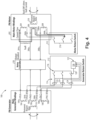
- the return switch units 112, 212 can operate together in the event of a fault in either the PM motor main legs 204a, 206a, 208a (as shown in Fig. 4 ) or the PM generator main legs 104a, 106a, 108a (as shown in Fig.
- the neutral nodes 116, 216 can optionally be floating neturals as shown in Fig. 4 , or can be both grounded, e.g. to a ground 130 aboard an aircraft, as shown in Fig. 5 . Grounding the neutral points 116, 216 makes possible ground fault detection, as schematically indicated in Fig. 5 .
- a method of fault protection includes rotating a permanent magnet, e.g. permanent magnets 110, 210, relative to a plurality of phase windings, e.g. phase windings 104, 106, 108 or 204, 206, 208, in a PM machine, e.g. PM machine 102, 202, as indicated by the double arrows in Figs. 1-5 .
- This includes generating power in the case of the PM machine operating as a generator, or driving a motor in the case of the PM machine operating as a motor.
- the method includes detecting a fault between at least two of the phase windings or a ground fault in any phase winding, and disconnecting respective return legs of all of the phase windings from a neutral point. This allows the permanent magnet to continue to rotate relative to the plurality of phase windings after the return legs are disconnected from the neutral point without ongoing damage.
- the stator electrical windings can be simplified allowing for improved manufacturability and reliability. There can be an ability to move protection circuits out of the PM machine into the same location as a generator/motor return switch, which lowers the volume of the PM machine and increases reliability.
- the systems and methods herein can allow for fast protection against electrical faults, e.g. as fast as fault protection techniques for synchronous machines.
- the systems and methods as disclosed herein can protects against many types of faults including line-line, 3-phase, and line-neutral.
- the systems and methods disclosed herein can be used in place of PM machine output contactors. The protection can be able to be reset if desired.
- Systems and methods disclosed herein do not rely on the PM machine going to low or zero speed.
- Systems and methods disclosed herein allow for the use of low impedance generators which do not have to limit fault current to the continuous current carrying capability of the conductors.
- the generator neutral can be available external to the machine for current/voltage sensing.
Landscapes
- Engineering & Computer Science (AREA)
- Power Engineering (AREA)
- Protection Of Generators And Motors (AREA)
- Control Of Eletrric Generators (AREA)
Abstract
Description
- The present disclosure relates to permanent magnet (PM) machines such as motors and generators, and more particularly to fault protection for PM machines.
- PM electrical machines have several advantages over other types of motors and generators, including weight, design simplicity and reliability. However, due to the use of permanent magnets these machines are always electrically energized when rotating, which creates difficulties when it comes to protecting against electrical faults. Typical wound field synchronous generator designs can remove excitation when a fault is detected and the generator will cease to produce voltage to feed the fault. This method is not available for fault removal in PM-based systems. It is also possible to use an electrically actuated mechanical disconnect to remove the PM machine from its input shaft when a fault is present, however these are typically not resettable during aircraft operation, and it can take some time for the machine to stop rotating while it is still energized. As aircraft move to HVDC (high voltage direct current), there is a desire to rely more on large permanent magnet machines for electrical generation and propulsion motors, however the higher voltages increase the risk of high energy short circuits and arcing faults which necessitate a safe and reliable means of fault isolation.
- The conventional techniques have been considered satisfactory for their intended purpose. However, there is an ever present need for improved systems and methods for fault protecting PM machines. This disclosure provides a solution for this need.
- A system includes a permanent magnet (PM) machine including a first phase winding and a second phase winding and a permanent magnet configured to rotate relative to the first and second phase windings. The first phase winding has a main leg and a return leg extending from the first phase winding. The second phase winding has a main leg and a return leg extending from the second phase winding. A return switch unit is operatively connected to the return legs of the first phase winding and the second phase winding. The return switch unit includes a switch configured to connect the return legs of the first phase and second phase to a neutral node in the return switch unit in a normal state, and to disconnect the return legs of the first and second phase windings from the neutral node in a fault protection state. The return legs of the first and second phase windings can extend external from the PM machine. The return switch unit can be external to PM machine.
- The return switch unit can include a feedback system configured to trigger the switch into the fault protection state upon a short circuit fault between the main phase legs of the first and second phase windings or a ground fault in one or both of the main phase legs. The feedback system can include one or more fault detection sensors operatively connected to logic and an actuator to drive the switch with a fault detected. The feedback system, can be located external to the PM machine.
- The PM machine further can include a third phase winding with a respective main phase leg and a respective return leg. The switch can be a triple pole single throw (3PST) switch connecting the return legs of the first, second, and third phase windings to the neutral node in the normal state, and disconnecting the return legs of the first, second, and third phase windings from the neutral node in the fault protection state. The neutral node can be connected to ground aboard an aircraft.
- The PM machine can be a generator, wherein the main legs of the first, second, and third phase windings connect to a rectifier. A main line contactor can connect between the rectifier and the main legs of the first, second, and third phase windings to selectively disconnect the generator from the rectifier.
- The PM machine can be a motor wherein the main legs of the first, second, and third phase windings connect to a motor controller, and wherein the return switch unit is a motor return switch unit. A PM generator can be included with a first phase winding, a second phase winding, and a third phase winding, wherein the first, second, and third phase windings of the PM generator connect to the main controller for supplying power to the motor.
- A generator return switch can be operatively connected to the return legs of the first, second, and third phase windings of the PM generator, wherein the generator return switch unit includes a switch configured to connect the return legs of the first, second, and third phase windings of the PM generator to a neutral node in the generator return switch unit in a normal state, and to disconnect the return legs of the first, second, and third phase windings of the PM generator from the neutral node in a fault protection state. The neutral node in the generator return switch unit and the neutral node in the motor return switch unit can both be grounded to a ground aboard an aircraft.
- A method of fault protection includes rotating a permanent magnet relative to a plurality of phase windings in a permanent magnet machine (PM). The method includes detecting a fault between at least two of the phase windings or a ground fault of one or both of the phase windings, disconnecting respective return legs of all of the phase windings from a neutral point, and allowing the permanent magnet to continue to rotate relative to the plurality of phase windings after the return legs are disconnected from the neutral point.
- The permanent magnet and phase windings can be part of a permanent magnet (PM) generator and the method can include generating power with the PM generator prior to disconnecting the return legs, and ceasing generation of power with the PM generator upon disconnecting the return legs while the permanent magnet continues to rotate relative to the phase windings. The permanent magnet and phase windings can be part of a permanent magnet (PM) motor and the method can include using electrical power supplied to the phase windings to power rotation of the permanent magnet in the PM motor prior to disconnecting the return legs, and ceasing to drive rotation of the permanent magnet relative to the phase windings upon disconnecting the return legs while the permanent magnet continues to rotate relative to the phase windings. The method can include grounding a neutral node of the phase windings prior to detecting the fault, wherein disconnecting includes disconnecting the return legs from the neutral node.
- These and other features of the systems and methods of the subject disclosure will become more readily apparent to those skilled in the art from the following detailed description of the preferred embodiments taken in conjunction with the drawings.
- So that those skilled in the art to which the subject disclosure appertains will readily understand how to make and use the devices and methods of the subject disclosure without undue experimentation, preferred embodiments thereof will be described in detail herein below with reference to certain figures, wherein:
-
Fig. 1 is a schematic view of an embodiment of a system constructed in accordance with the present disclosure, showing a permanent magnet (PM) machine with a return switch for fault protection; -
Fig. 2 is a schematic view of the system ofFig. 1 , showing a fault where two phases are short circuited; -
Fig. 3 is a schematic view of the system ofFig. 1 , showing the return switch opening the returns of the three phases to protect against the fault; -
Fig. 4 is schematic view of the system ofFig. 1 , showing the PM machine as a generator connected to power a second PM machine that is a motor, wherein both PM machines have a respective return switch for fault protection; and -
Fig. 5 is a schematic view of the PM machine ofFig. 4 , showing the neutral nodes of the return switches grounded instead of floating. - Reference will now be made to the drawings wherein like reference numerals identify similar structural features or aspects of the subject disclosure. For purposes of explanation and illustration, and not limitation, a partial view of an embodiment of a system in accordance with the disclosure is shown in
Fig. 1 and is designated generally byreference character 100. Other embodiments of systems in accordance with the disclosure, or aspects thereof, are provided inFigs. 2-5 , as will be described. The systems and methods described herein can be used to provide fault protection in permanent magnet (PM) machines such as generators and motors, even wherein the machine may continue to undergo rotor rotation after a fault manifests. - The
system 100 includes aPM machine 102, which is a generator but motors are also discussed below. ThePM machine 102 includes a first phase winding 104, a second phase winding 106, and a third phase winding 108. Apermanent magnet 110 is configured to rotate relative to the first, second, andthird phase windings Fig. 1 . The first phase winding 104 has amain leg 104a and areturn leg 104b extending from the first phase winding 104. The second phase winding 106 has amain leg 106a and areturn leg 106b extending from the second phase winding 106, and the third phase winding 108 similarly has amain leg 108a and areturn leg 108b. - A
return switch unit 112 is operatively connected to thereturn legs return legs PM machine 102. Thereturn switch unit 112 can be external toPM machine 102, however it is also contemplated that the return switch unit can be intergraded into a PM stator housing of thesystem 100. Thereturn switch unit 112 includes a triple pole single throw (3PST)switch 114 configured to connect thereturn legs neutral node 116 in thereturn switch unit 112 in a normal state as shown inFig. 1 . Theswitch 114 is configured to disconnect thereturn legs neutral node 116 in a fault protection state, including a short circuit of any two or three of themain legs Fig 2 . Theneutral node 116 can be a floating neutral, as shown inFigs 1-3 , or can be connected to ground such as a ground aboard an aircraft (not shown inFigs. 1-3 but seeFig. 5 ). If a grounded neutral is used, ground faults of themain legs return switch unit 112. The switch can disconnect thereturn legs main line contactor 118 disconnects themain legs box 120 inFigs. 1 and2 . - With continued reference to
Figs. 1 and2 , thereturn switch unit 112 includes afeedback system 122, configured to trigger theswitch 116 into the fault protection state shown inFig. 3 upon detection of a short circuit fault, as shown inFig. 2 , between any two or three of themain phase legs feedback system 122 includes one or morefault detection sensors 124 operatively connected tologic 126 that is connected to control anactuator 128 to drive theswitch 114 with a fault detected by the sensor(s) 124. Thefeedback system 122 is located external to thePM machine 102. The current flow inFig. 2 is indicated schematically with the heavy lined arrow, and is similarly indicated inFigs. 3-5 . - While shown and described above in the context of a PM generator, it is also contemplated with reference to
Fig. 4 that a return switch unit as described above can be used for fault protection in aPM motor 202. ThePM motor 202 in includesmain legs third phase windings bus component 120, which in this case includes a motor controller. Thereturn switch unit 212 is a motor return switch unit, selectively connecting thereturn legs phase windings neutral point 216 as described above with respect toFigs. 1-3 . While not pictured inFigs. 4-5 for sake of clarity in the drawings, thereturn switch unit 212 includes afeedback system 122, as described above for controlling the switch 214 for fault protection, energizing, and deenergizing thePM motor 202 as described above. ThePM generator 102 can be connected to themotor controller 120 for supplying power to thePM motor 202 through themain legs return switch units main legs Fig. 4 ) or the PM generatormain legs Fig. 2-3 ), or thereturn switch units motor neutral nodes Fig. 4 , or can be both grounded, e.g. to aground 130 aboard an aircraft, as shown inFig. 5 . Grounding theneutral points Fig. 5 . - A method of fault protection includes rotating a permanent magnet, e.g.
permanent magnets e.g. phase windings e.g. PM machine Figs. 1-5 . This includes generating power in the case of the PM machine operating as a generator, or driving a motor in the case of the PM machine operating as a motor. The method includes detecting a fault between at least two of the phase windings or a ground fault in any phase winding, and disconnecting respective return legs of all of the phase windings from a neutral point. This allows the permanent magnet to continue to rotate relative to the plurality of phase windings after the return legs are disconnected from the neutral point without ongoing damage. - Potential advantages of systems and methods as disclosed herein include the following. The stator electrical windings can be simplified allowing for improved manufacturability and reliability. There can be an ability to move protection circuits out of the PM machine into the same location as a generator/motor return switch, which lowers the volume of the PM machine and increases reliability. The systems and methods herein can allow for fast protection against electrical faults, e.g. as fast as fault protection techniques for synchronous machines. The systems and methods as disclosed herein can protects against many types of faults including line-line, 3-phase, and line-neutral. The systems and methods disclosed herein can be used in place of PM machine output contactors. The protection can be able to be reset if desired. Systems and methods disclosed herein do not rely on the PM machine going to low or zero speed. Systems and methods disclosed herein allow for the use of low impedance generators which do not have to limit fault current to the continuous current carrying capability of the conductors. The generator neutral can be available external to the machine for current/voltage sensing.
- While shown and described herein in the context of three-phase machines, those skilled in the art will readily appreciate that the systems and methods as disclosed herein can readily be scaled to multi-phase machines with any suitable number of phases. Similarly, those skilled in the art having had the benefit of this disclosure will readily appreciate that any suitable type of return switches can be used without departing from the scope of this disclosure, such as mechanical or solid state. Any combination of phases can be used in order to isolate fault currents in accordance with this disclosure.
- The methods and systems of the present disclosure, as described above and shown in the drawings, provide for fault protection in PM machines such as generators and motors, even wherein the machine may continue to undergo rotor rotation after a fault manifests. While the apparatus and methods of the subject disclosure have been shown and described with reference to preferred embodiments, those skilled in the art will readily appreciate that changes and/or modifications may be made thereto without departing from the scope of the subject disclosure.
Claims (15)
- A system comprising:a permanent magnet "PM" machine (102) including a first phase winding (104), a second phase winding (106), and a third phase winding (108) and a permanent magnet configured to rotate relative to the first, second, and third phase windings, wherein the first phase winding (104) has a main leg (106a) and a return leg (104b) extending from the first phase winding (104), wherein the second phase winding (106) has a main leg (106a) and a return leg (104b) extending from the second phase winding (106), and wherein the third phase winding (108) has a main phase leg and a return leg (104b) extending from the third phase winding (108); anda return switch unit operatively connected to the return legs (104b) of the first phase winding (104) and the second phase winding (106), wherein the return switch unit includes a switch configured to connect the return legs (104b) of the first phase and second phase to a neutral node in the return switch unit in a normal state, and to disconnect the return legs (104b) of the first and second phase windings (104, 106) from the neutral node in a fault protection state.
- The system as recited in claim 1, wherein the return switch unit includes a feedback system configured to trigger the switch into the fault protection state upon a short circuit fault between the main phase legs of the first and second phase windings or a ground fault in one or both of the main phase legs.
- The system as recited in claim 2, wherein the feedback system includes one or more fault detection sensors operatively connected to logic and an actuator to drive the switch with a fault detected, wherein the feedback system is located external to the PM machine (102).
- The system as recited in any preceding claim, wherein the return legs (104b) of the first and second phase windings extend external from the PM machine (102), and wherein the return switch unit is external to PM machine (102).
- The system as recited in any preceding claim, wherein the switch is a triple pole single throw "3PST" switch connecting the return legs (104b) of the first, second, and third phase windings to the neutral node in the normal state, and disconnecting the return legs (104b) of the first, second, and third phase windings from the neutral node in the fault protection state.
- The system as recited in clam 5, wherein the neutral node is connected to ground aboard an aircraft.
- The system as recited in claim 5, wherein the PM machine (102) is a generator, wherein the main legs of the first, second, and third phase windings connect to a rectifier.
- The system as recited in claim 7, further comprising a main line contactor connecting between the rectifier and the main legs of the first, second, and third phase windings to selectively disconnect the generator from the rectifier.
- The system as recited in claim 5, wherein the PM machine (102) is a motor wherein the main legs of the first, second, and third phase windings connect to a motor controller, and wherein the return switch unit is a motor return switch unit.
- The system as recited in claim 9, further comprising:a PM generator with a first phase winding (104), a second phase winding (106), and a third phase winding (108), wherein the first, second, and third phase windings of the PM generator connect to the main controller for supplying power to the motor; anda generator return switch operatively connected to the return legs (104b) of the first, second, and third phase windings of the PM generator, wherein the generator return switch unit includes a switch configured to connect the return legs (104b) of the first, second, and third phase windings of the PM generator to a neutral node in the generator return switch unit in a normal state, and to disconnect the return legs (104b) of the first, second, and third phase windings of the PM generator from the neutral node in a fault protection state.
- The system as recited in claim 10, wherein the neutral node in the generator return switch unit and the neutral node in the motor return switch unit are both grounded to a ground aboard an aircraft.
- A method of fault protection comprising:rotating a permanent magnet relative to a plurality of phase windings in a permanent magnet machine "PM" (102);detecting a fault between at least two of the phase windings or a ground fault of one or both of the phase windings; anddisconnecting respective return legs (104b) of all of the phase windings from a neutral point; andallowing the permanent magnet to continue to rotate relative to the plurality of phase windings after the return legs (104b) are disconnected from the neutral point.
- The method as recited in claim 12, wherein the permanent magnet and phase windings are part of a permanent magnet "PM" generator and further comprising:generating power with the PM generator prior to disconnecting the return legs (104b); andceasing generation of power with the PM generator upon disconnecting the return legs (104b) while the permanent magnet continues to rotate relative to the phase windings.
- The method as recited in claim 12, wherein the permanent magnet and phase windings are part of a permanent magnet "PM" motor and further comprising:using electrical power supplied to the phase windings to power rotation of the permanent magnet in the PM motor prior to disconnecting the return legs (104b); andceasing to drive rotation of the permanent magnet relative to the phase windings upon disconnecting the return legs (104b) while the permanent magnet continues to rotate relative to the phase windings.
- The method as recited in any of claims 12, 13 or 14, further comprising grounding a neutral node of the phase windings prior to detecting the fault, wherein disconnecting includes disconnecting the return legs (104b) from the neutral node.
Applications Claiming Priority (1)
| Application Number | Priority Date | Filing Date | Title |
|---|---|---|---|
| US17/860,550 US12081015B2 (en) | 2022-07-08 | 2022-07-08 | Permanent magnet machine fault protection |
Publications (1)
| Publication Number | Publication Date |
|---|---|
| EP4304081A1 true EP4304081A1 (en) | 2024-01-10 |
Family
ID=87157945
Family Applications (1)
| Application Number | Title | Priority Date | Filing Date |
|---|---|---|---|
| EP23183983.8A Pending EP4304081A1 (en) | 2022-07-08 | 2023-07-06 | Permanent magnet machine fault protection |
Country Status (2)
| Country | Link |
|---|---|
| US (1) | US12081015B2 (en) |
| EP (1) | EP4304081A1 (en) |
Citations (2)
| Publication number | Priority date | Publication date | Assignee | Title |
|---|---|---|---|---|
| US20070030606A1 (en) * | 2005-07-25 | 2007-02-08 | Honeywell International, Inc. | System and method for fault protection for permanent magnet machines |
| WO2013071937A1 (en) * | 2011-11-16 | 2013-05-23 | Vestas Wind Systems A/S | Protection of a permanent magnet generator |
Family Cites Families (5)
| Publication number | Priority date | Publication date | Assignee | Title |
|---|---|---|---|---|
| KR101306130B1 (en) * | 2007-05-29 | 2013-09-09 | 엘지전자 주식회사 | Motor Driver System and method for protecting motor drive |
| US7652858B2 (en) * | 2007-06-06 | 2010-01-26 | Gm Global Technology Operations, Inc. | Protection for permanent magnet motor control circuits |
| FR2933818B1 (en) | 2008-07-10 | 2010-09-03 | Alstom Transport Sa | ELECTRICAL POWER SYSTEM FOR PERMANENT MAGNET THREE PHASE MOTOR. |
| US8427092B2 (en) | 2010-10-18 | 2013-04-23 | Hamilton Sundstrand Corporation | High voltage DC electric power generating system with permanent magnet generator protection |
| CN104052373B (en) * | 2013-03-14 | 2017-04-12 | 通用电气公司 | motor fault protection system and method |
-
2022
- 2022-07-08 US US17/860,550 patent/US12081015B2/en active Active
-
2023
- 2023-07-06 EP EP23183983.8A patent/EP4304081A1/en active Pending
Patent Citations (2)
| Publication number | Priority date | Publication date | Assignee | Title |
|---|---|---|---|---|
| US20070030606A1 (en) * | 2005-07-25 | 2007-02-08 | Honeywell International, Inc. | System and method for fault protection for permanent magnet machines |
| WO2013071937A1 (en) * | 2011-11-16 | 2013-05-23 | Vestas Wind Systems A/S | Protection of a permanent magnet generator |
Also Published As
| Publication number | Publication date |
|---|---|
| US12081015B2 (en) | 2024-09-03 |
| US20240014646A1 (en) | 2024-01-11 |
Similar Documents
| Publication | Publication Date | Title |
|---|---|---|
| US7078826B2 (en) | Hybrid gas turbine engine starter-generator | |
| US9548605B2 (en) | Protection circuits and methods for electrical machines | |
| US20040027077A1 (en) | Gas turbine engine starter generator with switchable exciter stator windings | |
| US10090733B2 (en) | Electrical power supply for equipment carried by a rotary support | |
| US8035357B2 (en) | Fault clearing for permanent magnet machines | |
| IL46573A (en) | Field excitation system for a synchronous machine utilizing a rotating transformer/brushless exciter generating combination | |
| US6995478B2 (en) | Gas turbine engine starter generator that selectively changes the number of rotor poles | |
| WO2023008284A1 (en) | Power generator, coil element, motor, and aircraft | |
| CN103620947A (en) | A switch arrangement | |
| US7576508B2 (en) | Gas turbine engine starter generator with AC generator and DC motor modes | |
| US10734931B2 (en) | Brushless synchronous power generation apparatus | |
| US20230257127A1 (en) | Coordinated fault response in rectifiers of hybrid aircraft | |
| US12081015B2 (en) | Permanent magnet machine fault protection | |
| JP3774838B2 (en) | Accident detection and protection method when starting motor mode of synchronous generator motor, and synchronous generator motor | |
| US11840148B2 (en) | Hybrid aircraft having rectifier with integrated protection | |
| US20230261595A1 (en) | Fault tolerant turbo-generator system | |
| EP1381149B9 (en) | Starting of switched reluctance generators | |
| US20250286483A1 (en) | Detecting rotor demagnetization | |
| RU2861212C1 (en) | Marine propulsion drive | |
| KR101664162B1 (en) | Generator protection apparatus and method | |
| EP2104224B1 (en) | Fault clearing method for permanent magnet machines | |
| JPH07245872A (en) | Variable speed generator motor | |
| CN110578604A (en) | Electrical equipment | |
| CN120110218A (en) | Drive system and associated method | |
| Rajasekhar et al. | Reliability assessment and system performance improvement of ORV Sagar Nidhi propulsion system |
Legal Events
| Date | Code | Title | Description |
|---|---|---|---|
| PUAI | Public reference made under article 153(3) epc to a published international application that has entered the european phase |
Free format text: ORIGINAL CODE: 0009012 |
|
| STAA | Information on the status of an ep patent application or granted ep patent |
Free format text: STATUS: THE APPLICATION HAS BEEN PUBLISHED |
|
| AK | Designated contracting states |
Kind code of ref document: A1 Designated state(s): AL AT BE BG CH CY CZ DE DK EE ES FI FR GB GR HR HU IE IS IT LI LT LU LV MC ME MK MT NL NO PL PT RO RS SE SI SK SM TR |
|
| STAA | Information on the status of an ep patent application or granted ep patent |
Free format text: STATUS: REQUEST FOR EXAMINATION WAS MADE |
|
| 17P | Request for examination filed |
Effective date: 20240710 |
|
| RBV | Designated contracting states (corrected) |
Designated state(s): AL AT BE BG CH CY CZ DE DK EE ES FI FR GB GR HR HU IE IS IT LI LT LU LV MC ME MK MT NL NO PL PT RO RS SE SI SK SM TR |
|
| STAA | Information on the status of an ep patent application or granted ep patent |
Free format text: STATUS: EXAMINATION IS IN PROGRESS |
|
| 17Q | First examination report despatched |
Effective date: 20250902 |