EP4304009A1 - Reflective member with protective plate - Google Patents
Reflective member with protective plate Download PDFInfo
- Publication number
- EP4304009A1 EP4304009A1 EP22762869.0A EP22762869A EP4304009A1 EP 4304009 A1 EP4304009 A1 EP 4304009A1 EP 22762869 A EP22762869 A EP 22762869A EP 4304009 A1 EP4304009 A1 EP 4304009A1
- Authority
- EP
- European Patent Office
- Prior art keywords
- protective plate
- angle
- denoted
- incidence
- wave
- Prior art date
- Legal status (The legal status is an assumption and is not a legal conclusion. Google has not performed a legal analysis and makes no representation as to the accuracy of the status listed.)
- Pending
Links
Images






Classifications
-
- H—ELECTRICITY
- H01—ELECTRIC ELEMENTS
- H01Q—ANTENNAS, i.e. RADIO AERIALS
- H01Q1/00—Details of, or arrangements associated with, antennas
- H01Q1/42—Housings not intimately mechanically associated with radiating elements, e.g. radome
- H01Q1/422—Housings not intimately mechanically associated with radiating elements, e.g. radome comprising two or more layers of dielectric material
-
- H—ELECTRICITY
- H01—ELECTRIC ELEMENTS
- H01Q—ANTENNAS, i.e. RADIO AERIALS
- H01Q15/00—Devices for reflection, refraction, diffraction or polarisation of waves radiated from an antenna, e.g. quasi-optical devices
- H01Q15/14—Reflecting surfaces; Equivalent structures
Definitions
- the present disclosure relates to a protective plate-equipped reflective member.
- a reflective member such as a reflector that reflects or re-radiates incoming radio waves is known.
- Such a reflector is disclosed in, for example, Patent Document 1 as a configuration including a reflective board having a reflective surface that reflects incoming radio waves; a support building frame that is a structure body having multiple leg parts installed upright in a substantially vertical direction and configured to support the reflective board; and an adjustment mechanism that has a vertical direction adjustment mechanism that is coupled to each of the multiple leg parts in the support building frame and can vertically operate a coupling position with each leg part.
- Patent Document 2 discloses a reflection array having multiple elements aligned in a first axial direction and a second axial direction perpendicular to the first axial direction and configured to reflect incident waves. This reflection array reflects the incident wave in a desired direction not in a plane containing the incident wave and the specular reflection wave.
- Patent Document 3 discloses a configuration in which a reflective plate having a predetermined radius in a microwave transmission device is installed at a place affording an unobstructed view from both an antenna of a first base station antenna and an antenna of a second base station, thereby reflecting microwave radio waves and performing microwave radio communication between the first base station and the second base station.
- Reflectors are generally adjusted to face almost directly toward radio waves from a base station, and in the past, reflectors have often been installed in places where the view is unobstructed from the base station and out of reach of people, such as on mountaintops.
- 5G 5th generation mobile communication systems
- reflectors will also be installed in city center environments, due to the low diffraction of radio waves having high frequencies, i.e., due to the high straightness and short propagation distance.
- re-radiate means to resonate in response to incoming radio waves and to radiate radio waves whose phases have changed.
- narrow angle means that the angle with respect to the normal to the reflector is small.
- Wide angle means that the angle with respect to the normal to the reflector is large.
- a protective plate covering the reflector is required on the radio wave-incident side of the reflector to protect against dirt or the like caused by human contact.
- the present disclosure has been made in view of the above and an object is to provide a protective plate-equipped reflective member that can effectively reflect or re-radiate radio waves incident on the reflective member over a wide angular range from a narrow angle to a wide angle.
- a protective plate-equipped reflective member that can effectively reflect or re-radiate incoming radio waves over a wide angular range from a narrow angle to a wide angle can be provided.
- FIG. 1 is a diagram illustrating a protective plate-equipped reflector according to the first embodiment.
- a protective plate-equipped reflector 1 is a reflective member with a protective plate, i.e., a protective plate-equipped reflective member, that reflects incoming radio waves.
- FIG. 1 illustrates how radio waves approaching in an incident direction 21 are reflected in a reflection direction 22 by the protective plate-equipped reflector 1.
- the protective plate-equipped reflector 1 includes a protective plate 11 and a reflector 12.
- the protective plate 11 is a flat plate member that is permeable with respect to radio waves entering the protective plate-equipped reflector 1.
- the protective plate 11 is installed on the radio-wave incident side of the reflector 12 via an air layer 13 and covers the reflector 12 to protect the reflector 12 against dirt resulting from human contact and against other things.
- Resin or glass can be used for the material of the protective plate 11.
- resin fluorine resin is preferred and polytetrafluoroethylene (PTFE) is more preferred, from the standpoint of dirt repellence.
- n 2 represents the refractive index of the protective plate 11 whereas ⁇ r represents the relative permittivity of the protective plate 11.
- the relative permittivity ⁇ r is equal to the square of the refractive index n 2 .
- d represents the plate thickness of the protective plate 11.
- the reflector 12 is a reflective member and includes a reflective surface 121.
- the reflective surface 121 reflects any radio waves incident on the reflective surface 121 after having passed through the protective plate 11.
- the material of the reflector 12 there is no particular restriction on the material of the reflector 12, and, as such, materials suitable for reflecting radio waves can be selected accordingly.
- the reflective surface 121 is a flat surface.
- the normal to the protective plate-equipped reflector 1 is the same as the normal to the reflective surface 121. Also, since the reflective surface 121 and the protective plate 11 are parallel to each other, the normal to the protective plate-attached reflector 1 is the same as the normal to the protective plate 11.
- a first radio wave 211 passes through the first boundary surface 111 (i.e., the surface on which radio waves are incident) of the protective plate 11, whereas a second radio wave 212 is reflected by the first boundary surface 111.
- the angle of incidence ⁇ 1 is an angle with respect to the normal to the protective plate 11.
- the first radio waves 211 are refracted by the first boundary surface 111 and propagate inside the protective plate 11 in a direction indicated by the angle of refraction ⁇ 2 , and then reach a second boundary surface 112 (i.e., the surface opposite to the first boundary surface 111) of the protective plate 11.
- a second boundary surface 112 i.e., the surface opposite to the first boundary surface 111 of the protective plate 11.
- some pass through the second boundary surface 112 whereas others are reflected by the second boundary surface 112.
- Passing radio waves 211' passing through the second boundary surface 112 pass through the air layer 13, reach the reflective surface 121, and then are reflected by the reflective surface 121.
- the first radio wave 211 reflected by the second boundary surface 112 propagates inside the protective plate 11 toward the first boundary surface 111, refracts at the first boundary surface 111, and then exits the protective plate 11 to the outside in the reflection direction 22.
- an optical path difference occurs in accordance with an optical path along which the first radio wave 211 passed through the inside of the protective plate 11 with respect to the optical path of the second radio wave 212 that was reflected by the first boundary surface 111.
- the optical path difference is represented by the bold line ⁇ L in FIG. 1 .
- the reflection efficiency of radio waves by the protective plate-equipped reflector 1 is at maximum.
- the condition in which transmission loss at the protective plate 11 is minimum is, for example, the condition in which no reflection occurs at the protective plate 11.
- the reflection by the protective plate 11 approaches the non-reflection condition, and thus the transmission loss at the protective plate 11 is reduced.
- the phase of the second radio wave 212 changes by ⁇ due to the reflection at the first boundary surface 111.
- the phase of the first radio wave 211 does not change due to the reflection at the second boundary surface 112.
- the fixed-end reflection is a reflection that occurs when a radio wave incidents on a medium with a large refractive index from a medium with a small refractive index
- the free-end reflection is a reflection that occurs when a radio wave incidents on a medium with a small refractive index from a medium with a large refractive index.
- the reflection at the protective plate 11 is non-reflection owing to the peaks cancelling each other out.
- the peak of the amplitude means that the amplitude is the highest or the lowest.
- the anti-peak of the amplitude means that the amplitude is the highest or the lowest, opposite to what the peak is. For example, in a case where the peak of the amplitude is the highest, that is, the crest, the anti-peak of the amplitude is the lowest amplitude, that is, the valley. Alternatively, in a case where the peak of the amplitude is the lowest amplitude, then the anti-peak of the amplitude is the highest of the amplitude.
- the inventors conducted a diligent study considering each phase of the peak of the amplitude of the first radio wave 211 and the anti-peak of the amplitude of the second radio wave 212, based on the optical path difference ⁇ L. As a result, it was found that the transmission loss at the protective plate 11 can be effectively suppressed and the reflection efficiency of the radio waves by the protective plate-equipped reflector 1 can be ensured at a high level in a case where the plate thickness d of the protective plate 11 is determined in accordance with the following Equation (4) and Inequality (5).
- d ⁇ ⁇ ⁇ 0 / 1.75 ⁇ ⁇ r 0.555 1 ⁇ ⁇ ⁇ 1.25
- ⁇ 0 represents the wavelength [mm] specified with respect to the operating center frequency f 0 [Hz]
- d represents the plate thickness [mm] of the protective plate 11
- ⁇ r represents the relative permittivity of the protective plate 11 at the operating center frequency f 0 [Hz]
- ⁇ represents a constant.
- the operating center frequency f 0 represents the frequency serving as the center value among the frequencies of radio waves incident on the protective plate-equipped reflector 1.
- the wavelength ⁇ 0 [mm] is defined by 1,000 ⁇ c/f 0 .
- the symbol c represents the speed of light and is approximately 3.0 ⁇ 10 8 m/s.
- Equation (4) and Inequality (5) apply to both transverse electric waves (TE waves) and transverse magnetic waves (TM waves) in radio waves.
- the present embodiment includes both TE and TM waves.
- the relative permittivity of the protective plate 11 is preferably 2 or more and 10 or less, and more preferably 2 or more and 5 or less. As long as the relative permittivity is in such a range, the protective film can be designed more easily with good characteristics over a wide band and at wide angles.
- FIG. 2 is a diagram illustrating an example of the relationship between the operating center frequency f 0 , constant ⁇ , and angle of incidence according to this embodiment.
- the horizontal axis in FIG. 2 represents constant ⁇ , whereas the vertical axis in FIG. 2 represents f/f 0 that is the ratio of the operating frequency f [Hz] to the operating center frequency f 0 .
- the concentration indicated by a color bar 30 represents the angle of incidence of the radio wave at which the normalized transmission loss is 1 dB.
- the white side with the lower concentration indicated by the color bar 30 indicates that the angle of incidence is larger and that the radio wave enters the protective plate 11 at a wider angle, whereas the black side with the higher concentration indicates that the angle of incidence is smaller and that the radio wave enters the protective plate 11 at a narrower angle.
- the normalized transmission loss is the transmission loss normalized such that the smallest transmission loss is 0 dB when f/f 0 is 1.0.
- the angle of incidence of the radio wave whose normalized transmission loss is 1 dB is referred to as the allowable angle of incidence.
- FIG. 2 illustrates the results of calculating the allowable angle of incidence by electromagnetic field analysis while changing the constant ⁇ and the operating frequency f, with the relative permittivity ⁇ r and the operating center frequency f 0 determined in advance.
- the CST Studio Suite was used for the analysis.
- f 0 is 28 GHz
- f is greater than or equal to 20 GHz and less than or equal to 50 GHz
- f/f 0 is greater than or equal to 0.714 and less than or equal to 1.786.
- a point 33 indicates that f/f 0 is 1.0 and that the constant ⁇ is 1.1.
- An area 40 indicated by horizontal hatching is an area for which no calculation has been performed.
- the constant ⁇ that which makes the allowable angle of incidence as large as possible is determined in accordance with FIG. 2 , and then plate thickness d is determined by substituting the constant ⁇ , the relative permittivity ⁇ r , and the wavelength ⁇ 0 specified by the operating center frequency f 0 into Equation (4).
- the constant ⁇ is determined such that the range of f/f 0 becomes as wide as possible.
- ⁇ f [Hz] The frequency range in which f/f 0 is 0.9 to 1.1 and ⁇ f/f 0 is 20% are ensured.
- the region between a lower boundary line 31 and an upper boundary line 32 is the region where the allowable angle of incidence is 60 degrees or more.
- a target region 34 enclosed by a square of dashed lines is the region where the constant ⁇ satisfies Inequality (5) and f/f 0 is greater than or equal to 0.9 and less than or equal to 1.1.
- the constant ⁇ is greater than or equal to 1 and less than or equal 1.23.
- the value of ⁇ f/f 0 is preferably 10% or more, more preferably 15% or more, and even more preferably 20% or more.
- Example 1 is a comparative example whereas Examples 2 to 4 are Examples.
- the protective plate 11 is made of PTFE
- the operating center frequency f 0 is 28 GHz
- the constant ⁇ is 0.097
- the plate thickness d is 3.7 mm.
- PTFE has a relative permittivity ⁇ r of 2.1 and a loss factor tan ⁇ of 0.001.
- the plate thickness d in Example 1 was determined using Equation (3) described above such that the phase of the peak of the amplitude in the radio wave reflected at the first boundary surface 111 and the phase of the anti-peak of the amplitude in the radio wave reflected at the second boundary surface 112 among the radio waves incident on the protective plate 11 at an angle of incidence of 0 degrees are aligned.
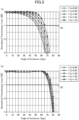
- FIG. 3 illustrates the relationship between the angle of incidence and normalized transmission loss in Example 1.
- FIG. 3(a) illustrates the TE wave whereas FIG. 3(b) illustrates the TM wave.
- FIG. 3 illustrates the normalized transmission loss calculated by electromagnetic field analysis when the angle of incidence is changed. CST Studio Suite was used for the analysis.
- the horizontal axis in FIG. 3 represents the angle of incidence of the radio wave with respect to the protective plate 11, whereas the vertical axis represents the normalized transmission loss.
- the cases, with f/f 0 being from 0.90 to 1.10 in 0.05 increments, are illustrated.
- a threshold 50 represents a normalized transmission loss of 1 dB.
- the view and meanings of drawings are the same in Examples 2 to 4 below.
- Example 1 the normalized transmission loss was the lowest when the angle of incidence was 0 degrees for all of the f/fo, and gradually increased as the angle of incidence increased.
- the allowable angle of incidence was 52 degrees when f/f 0 was 0.90, and this was the lowest one.
- the difference between the values of f/f 0 was small compared to that of the TE wave.
- the protective plate 11 is made of PTFE, the operating center frequency f 0 is 28 GHz, and the constant ⁇ is 1.1.
- the plate thickness d was determined by the above equation (4).
- PTFE has a relative permittivity ⁇ r of 2.1 and a loss factor tan ⁇ of 0.001.
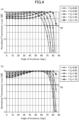
- FIG. 4 illustrates the relationship between the angle of incidence and the normalized transmission loss in Example 2.
- FIG. 4(a) illustrates the TE wave whereas FIG. 4(b) illustrates the TM wave.
- Example 2 As illustrated in FIG. 4 , in Example 2, for both the TE and TM waves, the normalized transmission loss was smallest where f/f 0 was 0.90 in the case where the angle of incidence was 0 degrees, and the normalized transmission loss increased as the f/f 0 was increased.
- the normalized transmission loss of the protective plate 11 decreased as the angle of incidence of the radio wave changed from 0 degrees to 50 degrees at the operating center frequency f 0 (f/f 0 is 1.0), and then after reaching the minimum value, the normalized loss of the protective plate 11 increased.
- the allowable angle of incidence was 65 degrees when f/f 0 was 0.90, and this was the lowest one. Therefore, the lowest allowable angle of incidence for the TE wave in Example 2 is large compared to 52 degrees in Example 1.
- the lowest allowable angle of incidence refers to the lowest of the allowable angles of incidence.
- the allowable angle of incidence was 77 degrees when f/f 0 is 0.90, and this was the lowest one. Therefore, the lowest allowable angle of incidence of the TE wave in Example 2 is large compared to 74 degrees in Example 1.
- Example 2 From the above, it was found that the lowest allowable angle of incidence of both TE and TM waves is large and a wide angle in Example 2 compared to Example 1.
- Example 1 and Example 2 only differ from each other in terms of the method of determining the plate thickness d of the protective plate 11, and, as such, the other conditions are the same. Therefore, by the method of determining the plate thickness d in Example 2, it was found that the protective plate-equipped reflector 1 can more effectively reflect or re-radiate radio waves incident the protective plate-equipped reflector 1 over a wider angular range than that of the comparative example.
- the protective plate 11 is made of PTFE, the operating center frequency f 0 is 40 GHz, and the constant ⁇ is 1.1.
- the plate thickness d was determined by the above Equation (4).
- PTFE has a relative permittivity ⁇ r of 2.1 and a loss factor tan ⁇ of 0.001.
- FIG. 5 illustrates the relationship between the angle of incidence and normalized transmission loss in Example 3.
- FIG. 5(a) illustrates the TE wave whereas FIG. 5(b) illustrates the TM wave.
- Example 3 As illustrated in FIG. 5 , in Example 3, almost the same results as in Example 2 were obtained, and it was found that the relationship between the angle of incidence and the normalized transmission loss was almost unchanged even when the operating center frequency f 0 changed.
- the protective plate 11 is made of glass, the operating center frequency f 0 is 28 GHz, and the constant ⁇ is 1.0.
- the plate thickness d was determined by the above Equation (4).
- the glass has a relative permittivity ⁇ r of 6.8 and a loss factor tan ⁇ of 0.02.
- FIG. 6 illustrates the relationship between the angle of incidence and normalized transmission loss in Example 4.
- FIG. 6(a) illustrates the TE wave whereas
- FIG. 6(b) illustrates the TM wave.
- FIG. 6 illustrates only when f/f 0 is 1.0.
- the allowable angle of incidence is 68 degrees.
- the normalized transmission loss is no greater than 1 dB even at 85 degrees, which is the highest angle of incidence.
- the protective plate-equipped reflector 1 has the reflector 12 that reflects incoming radio waves and the protective plate 11 that is installed on the radio wave-incident side of the reflector 12. Also, in a case where the wavelength specified with respect to the operating center frequency f 0 Hz is denoted by ⁇ 0 [mm], the plate thickness of the protective plate 11 is denoted by d [mm], the relative permittivity of the protective plate 11 at the operating center frequency f 0 Hz is denoted by ⁇ r , and the constant is denoted by ⁇ , d is equal to ⁇ ⁇ ⁇ 0 /(1.75 ⁇ ⁇ r 0.555 ), and ⁇ is greater than or equal to 1 and less than or equal to 1.25.
- the angular range of an angle of incidence in which the normalized transmission loss at the protective plate 11 becomes 1 dB can be widened, and the protective plate-equipped reflector 1, that can reflect radio waves well in a wide angular range from a narrow angle to a wide angle, can be provided.
- a protective plate-equipped reflector according to the second embodiment is described.
- the components that are the same as those in the first embodiment are denoted by the same reference numerals, and redundant descriptions are omitted accordingly.
- FIG. 7 is a diagram illustrating a configuration of a protective plate-equipped reflector 1a according to the second embodiment.
- the protective plate-equipped reflector 1a includes a protective plate 11a.
- the protective plate 11a has a first dielectric layer 51 and a second dielectric layer 52 that is provided between the first dielectric layer 51 and the reflector 12.
- the function of the protective plate-equipped reflector 1a is substantially the same as that of the protective plate-equipped reflector 1, and the function of the protective plate 11a is substantially the same as that of the protective plate 11.
- Resin or the like can be used for the material of the first dielectric layer 51, and resin, glass, or the like can be used for the material of the second dielectric layer 52. Since the first dielectric layer 51 is exposed to the outside air, it is preferable that the material has excellent weather resistance, excellent chemical resistance, excellent abrasion resistance, excellent heat resistance, and the like. Since the second dielectric layer 52 is not exposed to the outside air, it is preferable that the material has excellent availability, excellent processability, excellent affordability, and so on.
- the protective plate 11a can be fabricated, for example, by forming the second dielectric layer 52 and then covering the surface of the second dielectric layer 52 opposite to the surface of the dielectric layer 52 facing the reflector 12 with the first dielectric layer 51.
- FIG. 8 is a diagram illustrating the relative permittivity and layer thickness of the protective plate 11a.
- the effective relative permittivity ⁇ ra and the plate thickness da of the protective plate 11a are expressed by the following Equation (6) and Equation (7), where the layer thickness of the first dielectric layer 51 is denoted by d 1 [mm], the relative permittivity of the first dielectric layer 51 is denoted by ⁇ r1 , the layer thickness of the second dielectric layer 52 is denoted by d 2 [mm], and the relative permittivity of the second dielectric layer 52 is denoted by ⁇ r2 .
- Examples of the second embodiment are described below, but the present disclosure is not limited in any way to these examples. Examples 5 to 10 are all Examples.
- the normalized transmission losses at varying angles of incidence were calculated and evaluated by electromagnetic field analysis using the CST Studio Suite under seven different conditions, A to G, each with a different f/f 0 and constant ⁇ .
- FIG. 9 is a diagram illustrating f/f 0 and constant ⁇ under each of the conditions A to G.
- FIG. 9 illustrates the relationship between f/fo, constant ⁇ , and the angle of incidence as in FIG. 2 , and plots f/f 0 and constant ⁇ under each of the conditions A to G.
- the materials used for the first dielectric layer 51 include PTFE, Poly Vinylidene Di-fluoride (PVDF); Perfluoroalkoxy Alkane (PFA), and Ethylene Tetrafluoro Ethylene (ETFE).
- Table 1 below illustrates the relative permittivity ⁇ r1 and tan ⁇ 1 of each of these materials. [Table 1] Material ⁇ r1 tan ⁇ 1 PTFE 2.1 0.0002 PVDF 7.4 0.033 PFA 2.1 0.0003 ETFE 2.55 0.0028
- the materials used for the second dielectric layer 52 include Polycarbonate (PC), Polyvinyl chloride (PVC), Acrylonitrile Butadiene Styrene (ABS) resin, Polyethylene Terephthalate (PET), and glass.
- PC Polycarbonate
- PVC Polyvinyl chloride
- ABS Acrylonitrile Butadiene Styrene
- PET Polyethylene Terephthalate
- Table 2 below illustrates the relative permittivity ⁇ r2 and tan ⁇ 2 of each of these materials. [Table 2] Material ⁇ r2 tan ⁇ 2 PC 2.9 0.09 PVC 2.95 0.0125 ABS 3.1 0.011 PET 3.075 0.0527 Glass 6.8 0.016
- Table 3 illustrates the details of conditions A to G in Example 5 and the evaluation result under each condition.
- first layer indicates the material of the first dielectric layer 51 and the term “second layer” indicates the material of the second dielectric layer 52.
- FIG. 10 is a diagram illustrating a relationship between an angle of incidence and normalized transmission loss in Example 5.
- FIG. 10(a) is a diagram of the TE wave whereas FIG. 10(b) is a diagram of the TM wave.
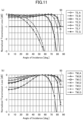
- Each graph in FIG. 10 indicates the result under each condition. These points are the same in FIGS. 11 to 15 illustrated below.
- Example 5 As illustrated in Table 3 and FIG. 10 , in Example 5, the evaluation was “Bad” under conditions F and G, and “Good” under the other conditions.
- Table 4 illustrates the details of conditions A to G in Example 6 and the evaluation result under each condition.
- [Table 4] f/f 0 f ⁇ First layer d 1 Second layer d 2 da Evaluation A 1.00 28.0 1.10 PTFE 0.05 PVC 3.66 3.71 Good B 0.95 26.6 1.10 PTFE 0.05 PVC 3.66 3.71 Good C 1.05 29.4 1.10 PTFE 0.05 PVC 3.66 3.71 Good D 1.00 28.0 1.05 PTFE 0.05 PVC 3.49 3.54 Good E 1.00 28.0 1.15 PTFE 0.05 PVC 3.82 3.87 Good F 0.85 23.8 0.95 PTFE 0.05 PVC 3.15 3.20 Bad G 1.15 32.2 1.15 PTFE 0.05 PVC 4.16 4.21 Bad
- FIG. 11 illustrates the relationship between the angle of incidence and normalized transmission loss in Example 6.
- FIG. 11(a) illustrates the TE wave whereas FIG. 11(b) illustrates the TM wave.
- Example 6 As illustrated in Table 4 and FIG. 11 , in Example 6, the evaluation was "Bad” under conditions F and G, and “Good” under the other conditions.
- Table 5 illustrates the details of conditions A to G in Example 7 and the evaluation result under each condition.
- [Table 5] f/f 0 f ⁇ First layer d 1 Second layer d 2 da Evaluation A 1.00 28.0 1.10 PTFE 0.05 ABS 3.56 3.61 Good B 0.95 26.6 1.10 PTFE 0.05 ABS 3.56 3.61 Good C 1.05 29.4 1.10 PTFE 0.05 ABS 3.56 3.61 Good D 1.00 28.0 1.05 PTFE 0.05 ABS 3.39 3.44 Good E 1.00 28.0 1.15 PTFE 0.05 ABS 3.72 3.77 Good F 0.85 23.8 0.95 PTFE 0.05 ABS 3.07 3.12 Bad G 1.15 32.2 1.15 PTFE 0.05 ABS 4.05 4.10 Bad
- FIG. 12 illustrates the relationship between the angle of incidence and normalized transmission loss in Example 7.
- FIG. 12(a) illustrates the TE wave whereas FIG. 12(b) illustrates the TM wave.
- Example 7 As illustrated in Table 5 and FIG. 12 , in Example 7, the evaluation was "Bad” under conditions F and G, and “Good” under the other conditions.
- Table 6 illustrates the details of Condition A and Condition F in Example 8 and the evaluation result under each condition. [Table 6] f/f 0 f ⁇ First layer d 1 Second layer d 2 da Evaluation A 1.00 28.0 1.10 PTFE 0.05 Glass 2.33 2.38 Good F 0.85 23.8 0.95 PTFE 0.05 Glass 2.02 2.07 Bad
- FIG. 13 illustrates the relationship between the angle of incidence and normalized transmission loss in Example 8.
- FIG. 13(a) illustrates the TE wave whereas
- FIG. 13(b) illustrates the TM wave.
- Example 8 As illustrated in Table 6 and FIG. 13 , in Example 8, the evaluation was "Bad” under condition A and “Good” under condition F.
- Table 7 illustrates the details of conditions A to G in Example 9 and the evaluation result under each condition.
- [Table 7] f/f 0 f ⁇ First layer d 1 Second layer d 2 da Evaluation A 1.00 28.0 1.10 PTFE 0.05 PC 3.66 3.71 Good B 0.95 26.6 1.10 PTFE 0.05 PC 3.66 3.71 Good C 1.05 29.4 1.10 PTFE 0.05 PC 3.66 3.71 Good D 1.00 28.0 1.05 PTFE 0.05 PC 3.49 3.54 Good E 1.00 28.0 1.15 PTFE 0.05 PC 3.88 3.93 Good F 0.85 23.8 0.95 PTFE 0.05 PC 3.15 3.20 Bad G 1.15 32.2 1.15 PTFE 0.05 PC 4.17 4.22 Bad
- FIG. 14 illustrates the relationship between the angle of incidence and normalized transmission loss in Example 9.
- FIG. 14(a) illustrates the TE wave whereas FIG. 14(b) illustrates the TM wave.
- Example 9 As illustrated in Table 7 and FIG. 14 , in Example 9, the evaluation was "Bad” under conditions F and G, and “Good” under the other conditions.
- Table 8 illustrates the details of Condition A and Condition F in Example 10 and the evaluation result under each condition. [Table 8] f/f 0 f ⁇ First layer d 1 Second layer d 2 da Evaluation A 1.00 28.0 1.10 PVDF 0.05 Glass 2.27 2.32 Good F 0.85 23.8 0.95 PVDF 0.05 Glass 1.96 2.01 Bad
- FIG. 15 illustrates the relationship between the angle of incidence and normalized transmission loss in Example 10.
- FIG. 15(a) illustrates the TE wave whereas FIG. 15(b) illustrates the TM wave.
- Example 10 As illustrated in Table 8 and FIG. 15 , in Example 10, the evaluation was "Good” under condition A and “Bad” under condition F.
- the protective plate-equipped reflector 1a can obtain substantially the same effect as the protective plate-equipped reflector 1 according to the first embodiment. From the standpoint of widening the range satisfying the criterion in which the incident angle is 60 degrees or more and normalized transmission loss is less than or equal to the normalized transmission loss threshold of 1dB, it is preferable to use a material with a low relative permittivity for both the first dielectric layer 51 and the second dielectric layer 52.
Landscapes
- Physics & Mathematics (AREA)
- Electromagnetism (AREA)
- Aerials With Secondary Devices (AREA)
Abstract
Description
- The present disclosure relates to a protective plate-equipped reflective member.
- A reflective member such as a reflector that reflects or re-radiates incoming radio waves is known.
- Such a reflector is disclosed in, for example,
Patent Document 1 as a configuration including a reflective board having a reflective surface that reflects incoming radio waves; a support building frame that is a structure body having multiple leg parts installed upright in a substantially vertical direction and configured to support the reflective board; and an adjustment mechanism that has a vertical direction adjustment mechanism that is coupled to each of the multiple leg parts in the support building frame and can vertically operate a coupling position with each leg part. - In addition,
Patent Document 2 discloses a reflection array having multiple elements aligned in a first axial direction and a second axial direction perpendicular to the first axial direction and configured to reflect incident waves. This reflection array reflects the incident wave in a desired direction not in a plane containing the incident wave and the specular reflection wave. - Further,
Patent Document 3 discloses a configuration in which a reflective plate having a predetermined radius in a microwave transmission device is installed at a place affording an unobstructed view from both an antenna of a first base station antenna and an antenna of a second base station, thereby reflecting microwave radio waves and performing microwave radio communication between the first base station and the second base station. -
- [Patent Document 1] Unexamined
Japanese Patent Application Publication No. 2020-10304 - [Patent Document 2] Unexamined
Japanese Patent Application Publication No. 2014-30138 - [Patent Document 3] Unexamined
Japanese Patent Application Publication No. 2003-32165 - Reflectors are generally adjusted to face almost directly toward radio waves from a base station, and in the past, reflectors have often been installed in places where the view is unobstructed from the base station and out of reach of people, such as on mountaintops. However, in 5th generation mobile communication systems (5G) and beyond, it is envisioned that that reflectors will also be installed in city center environments, due to the low diffraction of radio waves having high frequencies, i.e., due to the high straightness and short propagation distance.
- In such situations, in order to reduce dead zones, there is demand for reflectors that effectively reflect or re-radiate radio waves that are incident on the reflector at a wide angular range from a narrow angle to a wide angle. Here, re-radiate means to resonate in response to incoming radio waves and to radiate radio waves whose phases have changed. Also, narrow angle means that the angle with respect to the normal to the reflector is small. Wide angle means that the angle with respect to the normal to the reflector is large.
- In a case where the reflector is installed near a person or a person's living space, however, a protective plate covering the reflector is required on the radio wave-incident side of the reflector to protect against dirt or the like caused by human contact.
- It has been found that when such a protective plate is installed using conventional technology, the efficiency of reflection or re-radiation by the reflective member with a protective plate such as a reflector, i.e., a protective plate-equipped reflective member, gets significantly reduced due to the large transmission loss in the protective plate with respect to the radio waves entering at a wide angle.
- The present disclosure has been made in view of the above and an object is to provide a protective plate-equipped reflective member that can effectively reflect or re-radiate radio waves incident on the reflective member over a wide angular range from a narrow angle to a wide angle.
- According to at least one embodiment of the present disclosure a protective plate-equipped reflective member includes a reflective member that reflects or re-radiates a radio wave incident thereon; and a protective plate that is installed on a radio wave-incident side of the reflective member, wherein d = α × λ0/(1.75 × εr 0.555) and α is greater than or equal to 1 and less than or equal to 1.25, where a wavelength specified with respect to an operating center frequency f0 [Hz] is denoted by λ0 [mm], a plate thickness of the protective plate is denoted by d [mm], a relative permittivity of the protective plate at the operating center frequency f0 [Hz] is denoted by εr, and a constant is denoted by α.
- According to the present disclosure, a protective plate-equipped reflective member that can effectively reflect or re-radiate incoming radio waves over a wide angular range from a narrow angle to a wide angle can be provided.
-
- [
FIG. 1] FIG. 1 is a diagram illustrating a protective plate-equipped reflector according to the first embodiment; - [
FIG. 2] FIG. 2 is a diagram illustrating a relationship between f/f0, constant α, and an angle of incidence; - [
FIG. 3] FIG. 3 is a diagram illustrating a relationship between an angle of incidence and normalized transmission loss in Example 1,FIG. 3(a) being a diagram of a TE wave andFIG. 3(b) being a diagram of a TM wave; - [
FIG. 4] FIG. 4 is a diagram illustrating a relationship between an angle of incidence and normalized transmission loss in Example 2,FIG. 4(a) being a diagram of the TE wave andFIG. 4(b) being a diagram of the TM wave; - [
FIG. 5] FIG. 5 is a diagram illustrating a relationship between an angle of incidence and normalized transmission loss in Example 3,FIG. 5(a) being a diagram of the TE wave andFIG. 5(b) being a diagram of the TM wave; - [
FIG. 6] FIG. 6 is a diagram illustrating a relationship between angle of incidence and normalized transmission loss in Example 4,FIG. 6(a) being a diagram of the TE wave andFIG. 6(b) being a diagram of the TM wave; - [
FIG. 7] FIG. 7 is a diagram illustrating a configuration of a protective plate-equipped reflector according to a second embodiment; - [
FIG. 8] FIG. 8 is a diagram illustrating the relative permittivity and layer thickness of a protective plate according to the second embodiment; - [
FIG. 9] FIG. 9 is a diagram illustrating conditions of f/f0 and constant α of the Examples of the second embodiment; - [
FIG. 10] FIG. 10 is a diagram illustrating a relationship between the an angle of incidence and normalized transmission loss in Example 5,FIG. 10(a) being a diagram of the TE wave andFIG. 10(b) being a diagram of the TM wave; - [
FIG. 11] FIG. 11 is a diagram illustrating a relationship between an angle of incidence and normalized transmission loss in Example 6,FIG. 11(a) being a diagram of the TE wave andFIG. 11(b) being a diagram of the TM wave; - [
FIG. 12] FIG. 12 is a diagram illustrating a relationship between an angle of incidence and normalized transmission loss in Example 7,FIG. 12(a) being a diagram of the TE wave andFIG. 12(b) is a diagram of the TM wave; - [
FIG. 13] FIG. 13 is a diagram illustrating the relationship between the angle of incidence and normalized transmission loss in Example 8,FIG. 13(a) being a diagram of the TE wave andFIG. 13(b) being a diagram of the TM wave; - [
FIG. 14] FIG. 14 is a diagram illustrating a relationship between an angle of incidence and normalized transmission loss in Example 9,FIG. 14(a) being a diagram of the TE wave andFIG. 14(b) being a diagram of the TM wave; and - [
FIG. 15] FIG. 15 is a diagram illustrating the relationship between an angle of incidence and normalized transmission loss in Example 10,FIG. 15(a) being a diagram of the TE wave andFIG. 15(b) being a diagram of the TM wave. - Hereinafter, embodiments of the present disclosure are described below with reference to the accompanying drawings. Throughout the drawings, the same components are denoted by the same reference numerals, and redundant descriptions are omitted accordingly.
-
FIG. 1 is a diagram illustrating a protective plate-equipped reflector according to the first embodiment. A protective plate-equippedreflector 1 is a reflective member with a protective plate, i.e., a protective plate-equipped reflective member, that reflects incoming radio waves.FIG. 1 illustrates how radio waves approaching in anincident direction 21 are reflected in areflection direction 22 by the protective plate-equippedreflector 1. As illustrated inFIG. 1 , the protective plate-equippedreflector 1 includes aprotective plate 11 and areflector 12. - The
protective plate 11 is a flat plate member that is permeable with respect to radio waves entering the protective plate-equippedreflector 1. Theprotective plate 11 is installed on the radio-wave incident side of thereflector 12 via anair layer 13 and covers thereflector 12 to protect thereflector 12 against dirt resulting from human contact and against other things. - Resin or glass can be used for the material of the
protective plate 11. In the case where resin is used, fluorine resin is preferred and polytetrafluoroethylene (PTFE) is more preferred, from the standpoint of dirt repellence. InFIG. 1 , n2 represents the refractive index of theprotective plate 11 whereas εr represents the relative permittivity of theprotective plate 11. The relative permittivity εr is equal to the square of the refractive index n2. Also, d represents the plate thickness of theprotective plate 11. - The
reflector 12 is a reflective member and includes areflective surface 121. Among the radio waves incident on the protective plate-equippedreflector 1, thereflective surface 121 reflects any radio waves incident on thereflective surface 121 after having passed through theprotective plate 11. There is no particular restriction on the material of thereflector 12, and, as such, materials suitable for reflecting radio waves can be selected accordingly. - In this embodiment, the
reflective surface 121 is a flat surface. The normal to the protective plate-equippedreflector 1 is the same as the normal to thereflective surface 121. Also, since thereflective surface 121 and theprotective plate 11 are parallel to each other, the normal to the protective plate-attachedreflector 1 is the same as the normal to theprotective plate 11. - Among the radio waves incident on the protective plate-equipped
reflector 1 at an angle of incidence θ1, afirst radio wave 211 passes through the first boundary surface 111 (i.e., the surface on which radio waves are incident) of theprotective plate 11, whereas asecond radio wave 212 is reflected by thefirst boundary surface 111. It is to be noted that the angle of incidence θ1 is an angle with respect to the normal to theprotective plate 11. - The
first radio waves 211 are refracted by thefirst boundary surface 111 and propagate inside theprotective plate 11 in a direction indicated by the angle of refraction θ2, and then reach a second boundary surface 112 (i.e., the surface opposite to the first boundary surface 111) of theprotective plate 11. Among thefirst radio waves 211 reaching thesecond boundary surface 112, some pass through thesecond boundary surface 112 whereas others are reflected by thesecond boundary surface 112. Passing radio waves 211' passing through thesecond boundary surface 112 pass through theair layer 13, reach thereflective surface 121, and then are reflected by thereflective surface 121. - In contrast to this, the
first radio wave 211 reflected by thesecond boundary surface 112 propagates inside theprotective plate 11 toward thefirst boundary surface 111, refracts at thefirst boundary surface 111, and then exits theprotective plate 11 to the outside in thereflection direction 22. - In the propagation of the
first radio wave 211, an optical path difference occurs in accordance with an optical path along which thefirst radio wave 211 passed through the inside of theprotective plate 11 with respect to the optical path of thesecond radio wave 212 that was reflected by thefirst boundary surface 111. The optical path difference is represented by the bold line ΔL inFIG. 1 . - Here, when transmission loss of radio waves passed through the
protective plate 11 is minimum, the reflection efficiency of radio waves by the protective plate-equippedreflector 1 is at maximum. The condition in which transmission loss at theprotective plate 11 is minimum is, for example, the condition in which no reflection occurs at theprotective plate 11. In this embodiment, by optimizing the plate thickness d of theprotective plate 11, the reflection by theprotective plate 11 approaches the non-reflection condition, and thus the transmission loss at theprotective plate 11 is reduced. - The relationship between the angle of incidence θ1 and the angle of refraction θ2 in the
protective plate 11 is expressed by the following Equation (1):
Equation 1
- The v ΔL, is expressed by the following Equation (2).
Equation 2
- Since the reflection at the
first boundary surface 111 is a fixed-end reflection, the phase of thesecond radio wave 212 changes by π due to the reflection at thefirst boundary surface 111. In contrast to this, since the reflection at thesecond boundary surface 112 is a free-end reflection, the phase of thefirst radio wave 211 does not change due to the reflection at thesecond boundary surface 112. It is to be noted that the fixed-end reflection is a reflection that occurs when a radio wave incidents on a medium with a large refractive index from a medium with a small refractive index, whereas the free-end reflection is a reflection that occurs when a radio wave incidents on a medium with a small refractive index from a medium with a large refractive index. - When the phases are aligned between the peak of the amplitude at the
first radio wave 211 and the anti-peak of the amplitude at thesecond radio wave 212, the reflection at theprotective plate 11 is non-reflection owing to the peaks cancelling each other out. The peak of the amplitude means that the amplitude is the highest or the lowest. The anti-peak of the amplitude means that the amplitude is the highest or the lowest, opposite to what the peak is. For example, in a case where the peak of the amplitude is the highest, that is, the crest, the anti-peak of the amplitude is the lowest amplitude, that is, the valley. Alternatively, in a case where the peak of the amplitude is the lowest amplitude, then the anti-peak of the amplitude is the highest of the amplitude. - Conventionally, the angle of incidence of radio waves is assumed to be approximately 0 degrees, so it is normal to determine the plate thickness such that the phase of the peak of the amplitude in the radio wave reflected at the
first boundary surface 111 and the phase of the anti-peak of the amplitude in the radio wave reflected at thesecond boundary surface 112 among the radio waves incident on theprotective plate 11 at the angle of incidence of 0 degrees are aligned. That is, the plate thickness d of the protective plate has been determined by the following Equation (3).
- However, with such a plate thickness, it is difficult to obtain a protective plate with good transmission characteristics at wide angles.
- The inventors conducted a diligent study considering each phase of the peak of the amplitude of the
first radio wave 211 and the anti-peak of the amplitude of thesecond radio wave 212, based on the optical path difference ΔL. As a result, it was found that the transmission loss at theprotective plate 11 can be effectively suppressed and the reflection efficiency of the radio waves by the protective plate-equippedreflector 1 can be ensured at a high level in a case where the plate thickness d of theprotective plate 11 is determined in accordance with the following Equation (4) and Inequality (5).

- Here, λ0 represents the wavelength [mm] specified with respect to the operating center frequency f0 [Hz], d represents the plate thickness [mm] of the
protective plate 11, εr represents the relative permittivity of theprotective plate 11 at the operating center frequency f0 [Hz], and α represents a constant. - The operating center frequency f0 represents the frequency serving as the center value among the frequencies of radio waves incident on the protective plate-equipped
reflector 1. The wavelength λ0 [mm] is defined by 1,000 × c/f0. The symbol c represents the speed of light and is approximately 3.0 × 10⁸ m/s. - Equation (4) and Inequality (5) apply to both transverse electric waves (TE waves) and transverse magnetic waves (TM waves) in radio waves. In other words, the present embodiment includes both TE and TM waves.
- The relative permittivity of the
protective plate 11 is preferably 2 or more and 10 or less, and more preferably 2 or more and 5 or less. As long as the relative permittivity is in such a range, the protective film can be designed more easily with good characteristics over a wide band and at wide angles. -
FIG. 2 is a diagram illustrating an example of the relationship between the operating center frequency f0, constant α, and angle of incidence according to this embodiment. The horizontal axis inFIG. 2 represents constant α, whereas the vertical axis inFIG. 2 represents f/f0 that is the ratio of the operating frequency f [Hz] to the operating center frequency f0. - The concentration indicated by a
color bar 30 represents the angle of incidence of the radio wave at which the normalized transmission loss is 1 dB. The white side with the lower concentration indicated by thecolor bar 30 indicates that the angle of incidence is larger and that the radio wave enters theprotective plate 11 at a wider angle, whereas the black side with the higher concentration indicates that the angle of incidence is smaller and that the radio wave enters theprotective plate 11 at a narrower angle. - Here, the normalized transmission loss is the transmission loss normalized such that the smallest transmission loss is 0 dB when f/f0 is 1.0. Hereinafter, for the sake of simplicity, the angle of incidence of the radio wave whose normalized transmission loss is 1 dB is referred to as the allowable angle of incidence.
-
FIG. 2 illustrates the results of calculating the allowable angle of incidence by electromagnetic field analysis while changing the constant α and the operating frequency f, with the relative permittivity εr and the operating center frequency f0 determined in advance. The CST Studio Suite was used for the analysis. In the example ofFIG. 2 , f0 is 28 GHz, f is greater than or equal to 20 GHz and less than or equal to 50 GHz, and f/f0 is greater than or equal to 0.714 and less than or equal to 1.786. - A
point 33 indicates that f/f0 is 1.0 and that the constant α is 1.1. Anarea 40 indicated by horizontal hatching is an area for which no calculation has been performed. - In this embodiment, the constant α that which makes the allowable angle of incidence as large as possible is determined in accordance with
FIG. 2 , and then plate thickness d is determined by substituting the constant α, the relative permittivity εr, and the wavelength λ0 specified by the operating center frequency f0 into Equation (4). - Here, in order to enhance robustness against variations in the operating frequency f, it is preferable that the constant α is determined such that the range of f/f0 becomes as wide as possible.
- The frequency range, in which the allowable angle of incidence is 60 degrees or more, around the operating center frequency f0, is denoted by Δf [Hz]. In this case, by having the constant α satisfy Inequality (5), the frequency range in which f/f0 is 0.9 to 1.1 and Δf/f0 is 20% are ensured.
- In
FIG. 2 , the region between alower boundary line 31 and anupper boundary line 32 is the region where the allowable angle of incidence is 60 degrees or more. Atarget region 34 enclosed by a square of dashed lines is the region where the constant α satisfies Inequality (5) and f/f0 is greater than or equal to 0.9 and less than or equal to 1.1. - In view of ensuring a large frequency range, it is more preferable that the constant α is greater than or equal to 1 and less than or equal 1.23. In view of enhancing robustness against variations in the operating frequency f, the value of Δf/f0 is preferably 10% or more, more preferably 15% or more, and even more preferably 20% or more.
- Examples and a comparative example are described below, but the present disclosure is by no means limited to these examples. Example 1 is a comparative example whereas Examples 2 to 4 are Examples.
- In Example 1, the
protective plate 11 is made of PTFE, the operating center frequency f0 is 28 GHz, the constant α is 0.097, and the plate thickness d is 3.7 mm. PTFE has a relative permittivity εr of 2.1 and a loss factor tan δ of 0.001. - The plate thickness d in Example 1 was determined using Equation (3) described above such that the phase of the peak of the amplitude in the radio wave reflected at the
first boundary surface 111 and the phase of the anti-peak of the amplitude in the radio wave reflected at thesecond boundary surface 112 among the radio waves incident on theprotective plate 11 at an angle of incidence of 0 degrees are aligned. -
FIG. 3 illustrates the relationship between the angle of incidence and normalized transmission loss in Example 1.FIG. 3(a) illustrates the TE wave whereasFIG. 3(b) illustrates the TM wave.FIG. 3 illustrates the normalized transmission loss calculated by electromagnetic field analysis when the angle of incidence is changed. CST Studio Suite was used for the analysis. The horizontal axis inFIG. 3 represents the angle of incidence of the radio wave with respect to theprotective plate 11, whereas the vertical axis represents the normalized transmission loss. In the legend, the cases, with f/f0 being from 0.90 to 1.10 in 0.05 increments, are illustrated. Athreshold 50 represents a normalized transmission loss of 1 dB. The view and meanings of drawings are the same in Examples 2 to 4 below. - As illustrated in
FIG. 3 , in Example 1, the normalized transmission loss was the lowest when the angle of incidence was 0 degrees for all of the f/fo, and gradually increased as the angle of incidence increased. For TE waves, the allowable angle of incidence was 52 degrees when f/f0 was 0.90, and this was the lowest one. - For the TM wave, the difference between the values of f/f0 was small compared to that of the TE wave. The allowable angle of incidence 74 degrees when f/f0 was 0.90, and this was the lowest one.
- In Example 2, the
protective plate 11 is made of PTFE, the operating center frequency f0 is 28 GHz, and the constant α is 1.1. The plate thickness d was determined by the above equation (4). PTFE has a relative permittivity εr of 2.1 and a loss factor tan δ of 0.001. -
FIG. 4 illustrates the relationship between the angle of incidence and the normalized transmission loss in Example 2.FIG. 4(a) illustrates the TE wave whereasFIG. 4(b) illustrates the TM wave. - As illustrated in
FIG. 4 , in Example 2, for both the TE and TM waves, the normalized transmission loss was smallest where f/f0 was 0.90 in the case where the angle of incidence was 0 degrees, and the normalized transmission loss increased as the f/f0 was increased. - Also, for both the TE and TM waves, the normalized transmission loss of the
protective plate 11 decreased as the angle of incidence of the radio wave changed from 0 degrees to 50 degrees at the operating center frequency f0 (f/f0 is 1.0), and then after reaching the minimum value, the normalized loss of theprotective plate 11 increased. - For the TE wave in Example 2, the allowable angle of incidence was 65 degrees when f/f0 was 0.90, and this was the lowest one. Therefore, the lowest allowable angle of incidence for the TE wave in Example 2 is large compared to 52 degrees in Example 1. The lowest allowable angle of incidence refers to the lowest of the allowable angles of incidence.
- For the TM wave in Example 2, the allowable angle of incidence was 77 degrees when f/f0 is 0.90, and this was the lowest one. Therefore, the lowest allowable angle of incidence of the TE wave in Example 2 is large compared to 74 degrees in Example 1.
- From the above, it was found that the lowest allowable angle of incidence of both TE and TM waves is large and a wide angle in Example 2 compared to Example 1.
- Example 1 and Example 2 only differ from each other in terms of the method of determining the plate thickness d of the
protective plate 11, and, as such, the other conditions are the same. Therefore, by the method of determining the plate thickness d in Example 2, it was found that the protective plate-equippedreflector 1 can more effectively reflect or re-radiate radio waves incident the protective plate-equippedreflector 1 over a wider angular range than that of the comparative example. - In Example 3, the
protective plate 11 is made of PTFE, the operating center frequency f0 is 40 GHz, and the constant α is 1.1. The plate thickness d was determined by the above Equation (4). PTFE has a relative permittivity εr of 2.1 and a loss factor tan δ of 0.001. -
FIG. 5 illustrates the relationship between the angle of incidence and normalized transmission loss in Example 3.FIG. 5(a) illustrates the TE wave whereasFIG. 5(b) illustrates the TM wave. - As illustrated in
FIG. 5 , in Example 3, almost the same results as in Example 2 were obtained, and it was found that the relationship between the angle of incidence and the normalized transmission loss was almost unchanged even when the operating center frequency f0 changed. - In Example 4, the
protective plate 11 is made of glass, the operating center frequency f0 is 28 GHz, and the constant α is 1.0. The plate thickness d was determined by the above Equation (4). The glass has a relative permittivity εr of 6.8 and a loss factor tan δ of 0.02. -
FIG. 6 illustrates the relationship between the angle of incidence and normalized transmission loss in Example 4.FIG. 6(a) illustrates the TE wave whereasFIG. 6(b) illustrates the TM wave.FIG. 6 illustrates only when f/f0 is 1.0. - As illustrated in
FIG. 6 , for the TE wave, the allowable angle of incidence is 68 degrees. For the TM wave, the normalized transmission loss is no greater than 1 dB even at 85 degrees, which is the highest angle of incidence. - When f/f0 is 0.9 or 1.1, although not illustrated, the result is slightly inferior to other examples. It is presumed that this is due to the protective plate having a relatively-high relative permittivity of 6.8.
- As described above, the protective plate-equipped
reflector 1 has thereflector 12 that reflects incoming radio waves and theprotective plate 11 that is installed on the radio wave-incident side of thereflector 12. Also, in a case where the wavelength specified with respect to the operating center frequency f0 Hz is denoted by λ0 [mm], the plate thickness of theprotective plate 11 is denoted by d [mm], the relative permittivity of theprotective plate 11 at the operating center frequency f0 Hz is denoted by εr, and the constant is denoted by α, d is equal to α × λ0/(1.75 × εr 0.555), and α is greater than or equal to 1 and less than or equal to 1.25. - As a result, the angular range of an angle of incidence in which the normalized transmission loss at the
protective plate 11 becomes 1 dB can be widened, and the protective plate-equippedreflector 1, that can reflect radio waves well in a wide angular range from a narrow angle to a wide angle, can be provided. - A protective plate-equipped reflector according to the second embodiment is described. The components that are the same as those in the first embodiment are denoted by the same reference numerals, and redundant descriptions are omitted accordingly.
-
FIG. 7 is a diagram illustrating a configuration of a protective plate-equippedreflector 1a according to the second embodiment. The protective plate-equippedreflector 1a includes aprotective plate 11a. Theprotective plate 11a has afirst dielectric layer 51 and asecond dielectric layer 52 that is provided between thefirst dielectric layer 51 and thereflector 12. The function of the protective plate-equippedreflector 1a is substantially the same as that of the protective plate-equippedreflector 1, and the function of theprotective plate 11a is substantially the same as that of theprotective plate 11. - Resin or the like can be used for the material of the
first dielectric layer 51, and resin, glass, or the like can be used for the material of thesecond dielectric layer 52. Since thefirst dielectric layer 51 is exposed to the outside air, it is preferable that the material has excellent weather resistance, excellent chemical resistance, excellent abrasion resistance, excellent heat resistance, and the like. Since thesecond dielectric layer 52 is not exposed to the outside air, it is preferable that the material has excellent availability, excellent processability, excellent affordability, and so on. - The
protective plate 11a can be fabricated, for example, by forming thesecond dielectric layer 52 and then covering the surface of thesecond dielectric layer 52 opposite to the surface of thedielectric layer 52 facing thereflector 12 with thefirst dielectric layer 51. -
FIG. 8 is a diagram illustrating the relative permittivity and layer thickness of theprotective plate 11a. The effective relative permittivity εra and the plate thickness da of theprotective plate 11a are expressed by the following Equation (6) and Equation (7), where the layer thickness of thefirst dielectric layer 51 is denoted by d1 [mm], the relative permittivity of thefirst dielectric layer 51 is denoted by εr1, the layer thickness of thesecond dielectric layer 52 is denoted by d2 [mm], and the relative permittivity of thesecond dielectric layer 52 is denoted by εr2.

- The
protective plate 11a satisfies the conditions expressed by Equation (8) and Inequality (9) below.

- Examples of the second embodiment are described below, but the present disclosure is not limited in any way to these examples. Examples 5 to 10 are all Examples.
- In each example, the normalized transmission losses at varying angles of incidence were calculated and evaluated by electromagnetic field analysis using the CST Studio Suite under seven different conditions, A to G, each with a different f/f0 and constant α.
-
FIG. 9 is a diagram illustrating f/f0 and constant α under each of the conditions A to G.FIG. 9 illustrates the relationship between f/fo, constant α, and the angle of incidence as inFIG. 2 , and plots f/f0 and constant α under each of the conditions A to G. - The materials used for the
first dielectric layer 51 include PTFE, Poly Vinylidene Di-fluoride (PVDF); Perfluoroalkoxy Alkane (PFA), and Ethylene Tetrafluoro Ethylene (ETFE). Table 1 below illustrates the relative permittivity εr1 and tan δ1 of each of these materials.[Table 1] Material εr1 tan δ1 PTFE 2.1 0.0002 PVDF 7.4 0.033 PFA 2.1 0.0003 ETFE 2.55 0.0028 - The materials used for the
second dielectric layer 52 include Polycarbonate (PC), Polyvinyl chloride (PVC), Acrylonitrile Butadiene Styrene (ABS) resin, Polyethylene Terephthalate (PET), and glass. Table 2 below illustrates the relative permittivity εr2 and tan δ2 of each of these materials.[Table 2] Material εr2 tan δ2 PC 2.9 0.09 PVC 2.95 0.0125 ABS 3.1 0.011 PET 3.075 0.0527 Glass 6.8 0.016 - In the evaluations, an evaluation of "Good" was given in a case where both TE and TM waves satisfied the criterion in which an angle of incidence is 60 degrees or more and the normalized transmission loss is less than or equal to the normalized transmission loss threshold of 1 dB, whereas an evaluation of "Bad" was given in a case where one or both of the TE and TM waves did not satisfy the criterion.
- Table 3 illustrates the details of conditions A to G in Example 5 and the evaluation result under each condition. In Table 3, the term "first layer" indicates the material of the
first dielectric layer 51 and the term "second layer" indicates the material of thesecond dielectric layer 52. These points are the same in Tables 4 to 8 illustrated below.[Table 3] f/f0 f α First layer d1 Second layer d2 da Evaluation A 1.00 28.0 1.10 PTFE 0.05 PC 3.69 3.74 Good B 0.95 26.6 1.10 PTFE 0.05 PC 3.69 3.74 Good C 1.05 29.4 1.10 PTFE 0.05 PC 3.69 3.74 Good D 1.00 28.0 1.05 PTFE 0.05 PC 3.57 3.62 Good E 1.00 28.0 1.15 PTFE 0.05 PC 3.86 3.91 Good F 0.85 23.8 0.95 PTFE 0.05 PC 3.18 3.23 Bad G 1.15 32.2 1.15 PTFE 0.05 PC 4.20 4.25 Bad -
FIG. 10 is a diagram illustrating a relationship between an angle of incidence and normalized transmission loss in Example 5.FIG. 10(a) is a diagram of the TE wave whereasFIG. 10(b) is a diagram of the TM wave. Each graph inFIG. 10 indicates the result under each condition. These points are the same inFIGS. 11 to 15 illustrated below. - As illustrated in Table 3 and
FIG. 10 , in Example 5, the evaluation was "Bad" under conditions F and G, and "Good" under the other conditions. - Table 4 illustrates the details of conditions A to G in Example 6 and the evaluation result under each condition.
[Table 4] f/f0 f α First layer d1 Second layer d2 da Evaluation A 1.00 28.0 1.10 PTFE 0.05 PVC 3.66 3.71 Good B 0.95 26.6 1.10 PTFE 0.05 PVC 3.66 3.71 Good C 1.05 29.4 1.10 PTFE 0.05 PVC 3.66 3.71 Good D 1.00 28.0 1.05 PTFE 0.05 PVC 3.49 3.54 Good E 1.00 28.0 1.15 PTFE 0.05 PVC 3.82 3.87 Good F 0.85 23.8 0.95 PTFE 0.05 PVC 3.15 3.20 Bad G 1.15 32.2 1.15 PTFE 0.05 PVC 4.16 4.21 Bad -
FIG. 11 illustrates the relationship between the angle of incidence and normalized transmission loss in Example 6.FIG. 11(a) illustrates the TE wave whereasFIG. 11(b) illustrates the TM wave. - As illustrated in Table 4 and
FIG. 11 , in Example 6, the evaluation was "Bad" under conditions F and G, and "Good" under the other conditions. - Table 5 illustrates the details of conditions A to G in Example 7 and the evaluation result under each condition.
[Table 5] f/f0 f α First layer d1 Second layer d2 da Evaluation A 1.00 28.0 1.10 PTFE 0.05 ABS 3.56 3.61 Good B 0.95 26.6 1.10 PTFE 0.05 ABS 3.56 3.61 Good C 1.05 29.4 1.10 PTFE 0.05 ABS 3.56 3.61 Good D 1.00 28.0 1.05 PTFE 0.05 ABS 3.39 3.44 Good E 1.00 28.0 1.15 PTFE 0.05 ABS 3.72 3.77 Good F 0.85 23.8 0.95 PTFE 0.05 ABS 3.07 3.12 Bad G 1.15 32.2 1.15 PTFE 0.05 ABS 4.05 4.10 Bad -
FIG. 12 illustrates the relationship between the angle of incidence and normalized transmission loss in Example 7.FIG. 12(a) illustrates the TE wave whereasFIG. 12(b) illustrates the TM wave. - As illustrated in Table 5 and
FIG. 12 , in Example 7, the evaluation was "Bad" under conditions F and G, and "Good" under the other conditions. - Table 6 illustrates the details of Condition A and Condition F in Example 8 and the evaluation result under each condition.
[Table 6] f/f0 f α First layer d1 Second layer d2 da Evaluation A 1.00 28.0 1.10 PTFE 0.05 Glass 2.33 2.38 Good F 0.85 23.8 0.95 PTFE 0.05 Glass 2.02 2.07 Bad -
FIG. 13 illustrates the relationship between the angle of incidence and normalized transmission loss in Example 8.FIG. 13(a) illustrates the TE wave whereasFIG. 13(b) illustrates the TM wave. - As illustrated in Table 6 and
FIG. 13 , in Example 8, the evaluation was "Bad" under condition A and "Good" under condition F. - Table 7 illustrates the details of conditions A to G in Example 9 and the evaluation result under each condition.
[Table 7] f/f0 f α First layer d1 Second layer d2 da Evaluation A 1.00 28.0 1.10 PTFE 0.05 PC 3.66 3.71 Good B 0.95 26.6 1.10 PTFE 0.05 PC 3.66 3.71 Good C 1.05 29.4 1.10 PTFE 0.05 PC 3.66 3.71 Good D 1.00 28.0 1.05 PTFE 0.05 PC 3.49 3.54 Good E 1.00 28.0 1.15 PTFE 0.05 PC 3.88 3.93 Good F 0.85 23.8 0.95 PTFE 0.05 PC 3.15 3.20 Bad G 1.15 32.2 1.15 PTFE 0.05 PC 4.17 4.22 Bad -
FIG. 14 illustrates the relationship between the angle of incidence and normalized transmission loss in Example 9.FIG. 14(a) illustrates the TE wave whereasFIG. 14(b) illustrates the TM wave. - As illustrated in Table 7 and
FIG. 14 , in Example 9, the evaluation was "Bad" under conditions F and G, and "Good" under the other conditions. - Table 8 illustrates the details of Condition A and Condition F in Example 10 and the evaluation result under each condition.
[Table 8] f/f0 f α First layer d1 Second layer d2 da Evaluation A 1.00 28.0 1.10 PVDF 0.05 Glass 2.27 2.32 Good F 0.85 23.8 0.95 PVDF 0.05 Glass 1.96 2.01 Bad -
FIG. 15 illustrates the relationship between the angle of incidence and normalized transmission loss in Example 10.FIG. 15(a) illustrates the TE wave whereasFIG. 15(b) illustrates the TM wave. - As illustrated in Table 8 and
FIG. 15 , in Example 10, the evaluation was "Good" under condition A and "Bad" under condition F. - As described above, the protective plate-equipped
reflector 1a can obtain substantially the same effect as the protective plate-equippedreflector 1 according to the first embodiment. From the standpoint of widening the range satisfying the criterion in which the incident angle is 60 degrees or more and normalized transmission loss is less than or equal to the normalized transmission loss threshold of 1dB, it is preferable to use a material with a low relative permittivity for both thefirst dielectric layer 51 and thesecond dielectric layer 52. - In the present embodiment, although configurations in which the protective plate-equipped
reflector 1 and the protective plate-equippedreflector 1a reflect incoming radio waves are illustrated, substantially the same working effect can be obtained in configurations in which protective plate-equippedreflector 1 and the protective plate-equippedreflector 1a re-radiate incoming radio waves. - Although preferred embodiments and other forms of the present disclosure have been described above in detail as examples, the present disclosure is by no means limited to these examples, and a variety of modifications and replacements can be introduced to the above examples without departing from the scope set forth in the claims.
- This application claims is based on and claims priority to
Japanese Patent Application No. 2021-031839, filed with the Japanese Patent Office on March 1, 2021 -
- 1, 1a
- Protective plate-equipped reflector
- 11, 11a
- Protective plate
- 111
- First boundary surface
- 112
- Second boundary surface
- 12
- Reflector
- 121
- Reflective surface
- 13
- Air layer
- 21
- Incident direction
- 211
- First radio wave
- 211'
- Passing radio wave
- 212
- Second radio wave
- 22
- Reflection direction
- 50
- Threshold
- 51
- First dielectric layer
- 52
- Second dielectric layer
- θ1
- Angle of incidence
- θ2
- Angle of refraction
- ΔL
- Optical path difference
- d, da, d1, d2
- Plate thickness
- εr, εr1, εr2
- Relative permittivity
- εra
- Effective relative permittivity
- n2
- Refractive index
- α
- Constant
- f
- Operating frequency
- f0
- Operating center frequency
- Δf
- Frequency range
Claims (7)
- A protective plate-equipped reflective member comprising:a reflective member that reflects or re-radiates a radio wave incident thereon; anda protective plate that is installed on a radio wave-incident side of the reflective member,wherein d = α × λ0/(1.75 × εr 0.555) and α is greater than or equal to 1 and less than or equal to 1.25, where a wavelength specified with respect to an operating center frequency f0 [Hz] is denoted by λ0 [mm], a plate thickness of the protective plate is denoted by d [mm], a relative permittivity of the protective plate at the operating center frequency f0 [Hz] is denoted by εr, and a constant is denoted by α.
- The protective plate-equipped reflective member according to claim 1, wherein the relative permittivity of the protective plate is 2 or more and 10 or less.
- The protective plate-equipped reflective member according to claim 1 or 2, wherein Δf/f0 is 10% or more, where a frequency range, in which an angle of incidence of the radio wave at which normalized transmission loss of the protective plate is 1 dB is 60 degrees or more, around the operating center frequency f0 [Hz], is denoted by Δf [Hz].
- The protective plate-equipped reflective member according to any one of claims 1 to 3, wherein a material of the protective plate is a fluorine resin or glass.
- The protective plate-equipped reflective member according to any one of claims 1 to 4, wherein a material of the protective plate is polytetrafluoroethylene.
- The protective plate-equipped reflective member according to any one of claims 1 to 5, wherein normalized transmission loss of the protective plate decreases as an angle of incidence of the radio wave changes from 0 degrees to 50 degrees at the operating center frequency f0 [Hz].
- The protective plate-equipped reflective member according to any one of claims 1 to 6, whereinthe protective plate includes a first dielectric layer and a second dielectric layer that is provided between the first dielectric layer and the reflective member, andεra = {(d1 + d2) × εr1 × εr2}/(d1 × εr2 + d2 × εr1), da = d1 + d2, da = α × λ0/(1.75 × εra 0.555), and α is greater than or equal to 1 and less than or equal to 1.25, where a layer thickness of the first dielectric layer is denoted by d1 [mm], a relative permittivity of the first dielectric layer is denoted by εr1, a layer thickness of the second dielectric layer is denoted by d2 [mm], a relative permittivity of the second dielectric layer is denoted by εr2, an effective relative permittivity of the protective plate is denoted by εra, and a plate thickness of the protective plate is denoted by da.
Applications Claiming Priority (2)
| Application Number | Priority Date | Filing Date | Title |
|---|---|---|---|
| JP2021031839 | 2021-03-01 | ||
| PCT/JP2022/003667 WO2022185811A1 (en) | 2021-03-01 | 2022-01-31 | Reflective member with protective plate |
Publications (2)
| Publication Number | Publication Date |
|---|---|
| EP4304009A1 true EP4304009A1 (en) | 2024-01-10 |
| EP4304009A4 EP4304009A4 (en) | 2025-01-22 |
Family
ID=83154994
Family Applications (1)
| Application Number | Title | Priority Date | Filing Date |
|---|---|---|---|
| EP22762869.0A Pending EP4304009A4 (en) | 2021-03-01 | 2022-01-31 | REFLECTIVE ELEMENT WITH PROTECTIVE PLATE |
Country Status (5)
| Country | Link |
|---|---|
| US (1) | US12362496B2 (en) |
| EP (1) | EP4304009A4 (en) |
| JP (1) | JP7722444B2 (en) |
| TW (1) | TW202235918A (en) |
| WO (1) | WO2022185811A1 (en) |
Families Citing this family (1)
| Publication number | Priority date | Publication date | Assignee | Title |
|---|---|---|---|---|
| CN116097425B (en) * | 2020-09-24 | 2025-11-21 | 株式会社村田制作所 | High-frequency module and communication device |
Family Cites Families (12)
| Publication number | Priority date | Publication date | Assignee | Title |
|---|---|---|---|---|
| JP2957473B2 (en) * | 1996-05-15 | 1999-10-04 | 静岡日本電気株式会社 | Microstrip antenna device |
| JP2003032165A (en) | 2001-07-12 | 2003-01-31 | Ntt Docomo Inc | Microwave transmission device and reflector used for it |
| EP2882036B1 (en) | 2012-07-31 | 2023-06-14 | Ntt Docomo, Inc. | Reflect array |
| JP5635567B2 (en) | 2012-07-31 | 2014-12-03 | 株式会社Nttドコモ | Reflect array |
| JP6654506B2 (en) * | 2016-05-23 | 2020-02-26 | 株式会社Soken | Radar equipment |
| US11336031B2 (en) * | 2017-05-16 | 2022-05-17 | Nihon Dengyo Kosaku Co., Ltd. | Antenna, array antenna, sector antenna, and dipole antenna |
| JP7119675B2 (en) | 2018-07-12 | 2022-08-17 | 中国電力株式会社 | Parasitic repeater |
| EP3922805A4 (en) * | 2019-02-06 | 2022-10-26 | Agc Inc. | ANTENNA UNIT, WINDOW GLASS WITH ANTENNA UNIT, AND ANTENNA UNIT INSTALLATION METHOD |
| JP6563159B6 (en) * | 2019-03-07 | 2019-10-23 | 三菱電機株式会社 | Antenna device |
| JP6962346B2 (en) * | 2019-03-26 | 2021-11-05 | 株式会社Soken | Antenna device |
| WO2020240364A1 (en) * | 2019-05-24 | 2020-12-03 | 3M Innovative Properties Company | Radar retroreflective article |
| JP7450204B2 (en) | 2019-08-14 | 2024-03-15 | ミサワホーム株式会社 | support structure |
-
2022
- 2022-01-31 JP JP2023503643A patent/JP7722444B2/en active Active
- 2022-01-31 EP EP22762869.0A patent/EP4304009A4/en active Pending
- 2022-01-31 WO PCT/JP2022/003667 patent/WO2022185811A1/en not_active Ceased
- 2022-02-08 TW TW111104519A patent/TW202235918A/en unknown
-
2023
- 2023-08-30 US US18/240,110 patent/US12362496B2/en active Active
Also Published As
| Publication number | Publication date |
|---|---|
| TW202235918A (en) | 2022-09-16 |
| WO2022185811A1 (en) | 2022-09-09 |
| US20230411863A1 (en) | 2023-12-21 |
| US12362496B2 (en) | 2025-07-15 |
| JPWO2022185811A1 (en) | 2022-09-09 |
| EP4304009A4 (en) | 2025-01-22 |
| JP7722444B2 (en) | 2025-08-13 |
Similar Documents
| Publication | Publication Date | Title |
|---|---|---|
| JP7548297B2 (en) | Wireless Transmission System | |
| US11967769B2 (en) | Planar antenna, layered antenna structure, and window glass for vehicle | |
| US20250174903A1 (en) | Frequency-selective reflecting plate and communication relay system | |
| US12362496B2 (en) | Protective plate-equipped reflective member | |
| US20180115059A1 (en) | Radio-wave transmitting cover and method for setting thickness of radio-wave transmitting cover | |
| US20250110265A1 (en) | Reflector | |
| US11962081B2 (en) | Antenna device | |
| US20200081161A1 (en) | Anti-reflection coating and method of forming the same | |
| CN120435802A (en) | Wireless transmission system | |
| KR102661547B1 (en) | Light-transmissive multispectral stealth device | |
| US7633457B2 (en) | Cladding for a microwave antenna | |
| Wiltse | Stepped conical zone plate antenna | |
| CN116953831B (en) | Infrared and laser compatible stealth membrane system structure based on DBR-metal | |
| EP4693745A1 (en) | Reflector | |
| CN217589423U (en) | Radar detection device | |
| CN119627454B (en) | A slit-enhanced, large-angle incident-insensitive, ultrawideband transparent absorber | |
| WO2024038682A1 (en) | Wireless transmission system | |
| WO2019123396A1 (en) | Radome structure for circular polarization antennas | |
| CN101040405A (en) | Cladding for a microwave antenna | |
| KR20250007781A (en) | Window structure | |
| WO2024157897A1 (en) | Radio wave propagation control member and antenna system | |
| TW202410553A (en) | Reflective panel, electromagnetic wave reflection device, and electromagnetic wave reflection fence | |
| Mahmoudi et al. | Analysis, design and fabrication of centimeter-wave dielectric Fresnel zone plate lens and reflector | |
| US20190086585A1 (en) | Optical component for controlling light emergent direction and manufacturing method thereof | |
| Sieber et al. | Stand-off detection of chemical analytes with passive chemo-sensing IR absorbers |
Legal Events
| Date | Code | Title | Description |
|---|---|---|---|
| STAA | Information on the status of an ep patent application or granted ep patent |
Free format text: STATUS: THE INTERNATIONAL PUBLICATION HAS BEEN MADE |
|
| PUAI | Public reference made under article 153(3) epc to a published international application that has entered the european phase |
Free format text: ORIGINAL CODE: 0009012 |
|
| STAA | Information on the status of an ep patent application or granted ep patent |
Free format text: STATUS: REQUEST FOR EXAMINATION WAS MADE |
|
| 17P | Request for examination filed |
Effective date: 20230831 |
|
| AK | Designated contracting states |
Kind code of ref document: A1 Designated state(s): AL AT BE BG CH CY CZ DE DK EE ES FI FR GB GR HR HU IE IS IT LI LT LU LV MC MK MT NL NO PL PT RO RS SE SI SK SM TR |
|
| DAV | Request for validation of the european patent (deleted) | ||
| DAX | Request for extension of the european patent (deleted) | ||
| A4 | Supplementary search report drawn up and despatched |
Effective date: 20250102 |
|
| RIC1 | Information provided on ipc code assigned before grant |
Ipc: H01Q 15/14 20060101ALI20241218BHEP Ipc: H01Q 1/42 20060101AFI20241218BHEP |