EP4303993A1 - A protective cover for protecting a ventilation device of a battery housing - Google Patents
A protective cover for protecting a ventilation device of a battery housing Download PDFInfo
- Publication number
- EP4303993A1 EP4303993A1 EP22183387.4A EP22183387A EP4303993A1 EP 4303993 A1 EP4303993 A1 EP 4303993A1 EP 22183387 A EP22183387 A EP 22183387A EP 4303993 A1 EP4303993 A1 EP 4303993A1
- Authority
- EP
- European Patent Office
- Prior art keywords
- protective cover
- opening
- airflow
- flange portion
- battery housing
- Prior art date
- Legal status (The legal status is an assumption and is not a legal conclusion. Google has not performed a legal analysis and makes no representation as to the accuracy of the status listed.)
- Granted
Links
Images



Classifications
-
- H—ELECTRICITY
- H01—ELECTRIC ELEMENTS
- H01M—PROCESSES OR MEANS, e.g. BATTERIES, FOR THE DIRECT CONVERSION OF CHEMICAL ENERGY INTO ELECTRICAL ENERGY
- H01M50/00—Constructional details or processes of manufacture of the non-active parts of electrochemical cells other than fuel cells, e.g. hybrid cells
- H01M50/30—Arrangements for facilitating escape of gases
- H01M50/394—Gas-pervious parts or elements
-
- H—ELECTRICITY
- H01—ELECTRIC ELEMENTS
- H01M—PROCESSES OR MEANS, e.g. BATTERIES, FOR THE DIRECT CONVERSION OF CHEMICAL ENERGY INTO ELECTRICAL ENERGY
- H01M50/00—Constructional details or processes of manufacture of the non-active parts of electrochemical cells other than fuel cells, e.g. hybrid cells
- H01M50/30—Arrangements for facilitating escape of gases
-
- H—ELECTRICITY
- H01—ELECTRIC ELEMENTS
- H01M—PROCESSES OR MEANS, e.g. BATTERIES, FOR THE DIRECT CONVERSION OF CHEMICAL ENERGY INTO ELECTRICAL ENERGY
- H01M50/00—Constructional details or processes of manufacture of the non-active parts of electrochemical cells other than fuel cells, e.g. hybrid cells
- H01M50/20—Mountings; Secondary casings or frames; Racks, modules or packs; Suspension devices; Shock absorbers; Transport or carrying devices; Holders
- H01M50/233—Mountings; Secondary casings or frames; Racks, modules or packs; Suspension devices; Shock absorbers; Transport or carrying devices; Holders characterised by physical properties of casings or racks, e.g. dimensions
- H01M50/24—Mountings; Secondary casings or frames; Racks, modules or packs; Suspension devices; Shock absorbers; Transport or carrying devices; Holders characterised by physical properties of casings or racks, e.g. dimensions adapted for protecting batteries from their environment, e.g. from corrosion
-
- H—ELECTRICITY
- H01—ELECTRIC ELEMENTS
- H01M—PROCESSES OR MEANS, e.g. BATTERIES, FOR THE DIRECT CONVERSION OF CHEMICAL ENERGY INTO ELECTRICAL ENERGY
- H01M50/00—Constructional details or processes of manufacture of the non-active parts of electrochemical cells other than fuel cells, e.g. hybrid cells
- H01M50/20—Mountings; Secondary casings or frames; Racks, modules or packs; Suspension devices; Shock absorbers; Transport or carrying devices; Holders
- H01M50/249—Mountings; Secondary casings or frames; Racks, modules or packs; Suspension devices; Shock absorbers; Transport or carrying devices; Holders specially adapted for aircraft or vehicles, e.g. cars or trains
-
- H—ELECTRICITY
- H01—ELECTRIC ELEMENTS
- H01M—PROCESSES OR MEANS, e.g. BATTERIES, FOR THE DIRECT CONVERSION OF CHEMICAL ENERGY INTO ELECTRICAL ENERGY
- H01M50/00—Constructional details or processes of manufacture of the non-active parts of electrochemical cells other than fuel cells, e.g. hybrid cells
- H01M50/30—Arrangements for facilitating escape of gases
- H01M50/35—Gas exhaust passages comprising elongated, tortuous or labyrinth-shaped exhaust passages
-
- H—ELECTRICITY
- H01—ELECTRIC ELEMENTS
- H01M—PROCESSES OR MEANS, e.g. BATTERIES, FOR THE DIRECT CONVERSION OF CHEMICAL ENERGY INTO ELECTRICAL ENERGY
- H01M50/00—Constructional details or processes of manufacture of the non-active parts of electrochemical cells other than fuel cells, e.g. hybrid cells
- H01M50/30—Arrangements for facilitating escape of gases
- H01M50/35—Gas exhaust passages comprising elongated, tortuous or labyrinth-shaped exhaust passages
- H01M50/358—External gas exhaust passages located on the battery cover or case
-
- H—ELECTRICITY
- H01—ELECTRIC ELEMENTS
- H01M—PROCESSES OR MEANS, e.g. BATTERIES, FOR THE DIRECT CONVERSION OF CHEMICAL ENERGY INTO ELECTRICAL ENERGY
- H01M50/00—Constructional details or processes of manufacture of the non-active parts of electrochemical cells other than fuel cells, e.g. hybrid cells
- H01M50/30—Arrangements for facilitating escape of gases
- H01M50/35—Gas exhaust passages comprising elongated, tortuous or labyrinth-shaped exhaust passages
- H01M50/367—Internal gas exhaust passages forming part of the battery cover or case; Double cover vent systems
-
- H—ELECTRICITY
- H01—ELECTRIC ELEMENTS
- H01M—PROCESSES OR MEANS, e.g. BATTERIES, FOR THE DIRECT CONVERSION OF CHEMICAL ENERGY INTO ELECTRICAL ENERGY
- H01M2220/00—Batteries for particular applications
- H01M2220/20—Batteries in motive systems, e.g. vehicle, ship, plane
-
- Y—GENERAL TAGGING OF NEW TECHNOLOGICAL DEVELOPMENTS; GENERAL TAGGING OF CROSS-SECTIONAL TECHNOLOGIES SPANNING OVER SEVERAL SECTIONS OF THE IPC; TECHNICAL SUBJECTS COVERED BY FORMER USPC CROSS-REFERENCE ART COLLECTIONS [XRACs] AND DIGESTS
- Y02—TECHNOLOGIES OR APPLICATIONS FOR MITIGATION OR ADAPTATION AGAINST CLIMATE CHANGE
- Y02E—REDUCTION OF GREENHOUSE GAS [GHG] EMISSIONS, RELATED TO ENERGY GENERATION, TRANSMISSION OR DISTRIBUTION
- Y02E60/00—Enabling technologies; Technologies with a potential or indirect contribution to GHG emissions mitigation
- Y02E60/10—Energy storage using batteries
Definitions
- the invention relates to a protective cover for protecting a ventilation device of a battery housing.
- the invention also relates to a ventilation arrangement, a battery housing and a vehicle.
- the invention can be applied in heavy-duty vehicles, such as trucks, buses and construction equipment. Although the invention will be described with respect to a truck, the invention is not restricted to this particular vehicle, but may also be used in other vehicles such as marine vessels, wheel loaders, excavators, buses and passenger cars.
- a battery unit for a vehicle such as a lithium-ion battery
- a battery housing for the battery unit is typically used for protecting the battery unit during use, e.g. during travelling of the vehicle.
- a battery housing with at least one ventilation device comprising an airflow opening which is arranged to provide an airflow between an inside of the battery housing and an external environment.
- the ventilation device may be arranged to regulate pressure level and moisture level inside the battery housing.
- an object of the invention is to provide a protective cover for protecting a ventilation device of a battery housing which alleviates at least one drawback of the prior art, or which at least provides a suitable alternative.
- Other objects of the invention are to provide a ventilation arrangement, a battery housing and/or a vehicle, which alleviate at least one drawback of the prior art, or which at least provide suitable alternatives.
- the object is at least partly achieved by a protective cover according to claim 1.
- a protective cover for protecting a ventilation device of a battery housing.
- the ventilation device comprises an airflow opening which is arranged to provide an airflow between an inside of the battery housing and an external environment
- the battery housing and/or the ventilation device comprises a first flange portion which extends around the airflow opening, and which further extends in a radially outward direction with respect to the airflow opening.
- the first flange portion forms a grip surface around the airflow opening for the protective cover.
- the protective cover comprises:
- the protective cover as disclosed herein, improved protection for the ventilation device is provided. More particularly, it has been realized that the ventilation function of the ventilation device may be impaired when the battery housing is used in a harsh environment. Thereby, by using the herein disclosed protective cover, the risk of impairing the ventilation function during use can be reduced. In addition, by the provision of the protective cover as disclosed herein, the mounting/dismounting procedures, i.e. attaching and releasing the protective cover to/from the ventilation device, can be improved. This is achieved by the specific configuration of the protective cover, i.e. that the protective cover comprises at least two separate parts.
- the at least two separate parts are further arranged to form the airflow duct when being attached to each other.
- the at least two separate parts are two halves of the protective cover which are releasably attachable to each other. This implies a facilitated mounting/dismounting procedure.
- the mounting/dismounting procedure may thereby require fewer operations by a user.
- the attachment portion comprises a second and a third flange portion which extend around an inner perimeter surface of the attachment portion, and which further extend in a radially inward direction thereof, corresponding to the radial direction of the airflow opening when the protective cover is attached to the first flange portion.
- the second and the third flange portions are offset from each other, as seen in an axial direction of the protective cover, the axial direction being perpendicular to the radial direction of the protective cover, thereby forming a gap therebetween so that the first flange portion can be accommodated in-between the second and the third flange portions.
- Radially inward and radially outward as used herein refers to radial directions with respect to a centre, in this case to a centre of the attachment portion, which may correspond to a centre of the airflow opening when the protective cover is attached to the ventilation device.
- the inner perimeter surface of the attachment portion may be annular, or round.
- the second flange portion comprises protrusions which extend in the radially inward direction, i.e. towards the centre of the attachment portion, wherein the protrusions are separated by intermediate recesses which extend radially outward so as to allow the protective cover to be attached to the first flange portion in more than one predefined angular position with respect to the first flange portion.
- the angular positions are angular positions with respect to a rotational axis of the protective cover.
- the rotational axis of the protective cover is preferably arranged to extend along a centre axis of the airflow opening when the protective cover is attached to the ventilation device.
- the protrusions are formed as teeth, such as teeth with sharp edges, for example triangular shaped protrusions, and/or as smooth outwardly bulging protrusions, such as curved-shaped portions.
- the protrusions as disclosed herein provides increased flexibility for the protective cover. More specifically, by being able to provide the protective cover in more than one predefined angular position with respect to the first flange portion, i.e. by being able to rotate the protective cover, the second opening can be oriented in different directions. Thereby, it can be assured that the second opening is not directed in less favourable directions. For example, it can be assured that the second opening is not pointing in a direction so that mud, or any other debris, is entered into the second opening during use.
- the airflow duct comprises a first airflow duct extension associated with the first opening and a second airflow duct extension associated with the second opening, wherein the first airflow duct extension extends in an axial direction of the protective cover, corresponding to an axial direction of the airflow opening when the protective cover is attached to the first flange portion, and wherein the second airflow duct extension is angled with respect to the first airflow duct extension, such as angled so that the second airflow duct extension extends substantially in the radial direction.
- a more compact protective cover can be provided where e.g. the second airflow duct extension extends in parallel to an outer surface of the battery housing during use. This configuration also implies that the second opening can be oriented in more favourable directions.
- the at least two separate parts further comprises fastening means for attaching the at least two separate parts to each other.
- the fastening means comprises any one of a screw, a bolt, a nut, a cable tie and a snap-fit connection member, such as a clip member.
- the protective cover comprises an outer peripheral surface, such as an annular outer peripheral surface, associated with the attachment portion, e.g. being provided radially outside the attachment portion, wherein the outer peripheral surface is adapted to receive a cable tie so that the attachment portion is clamped to the first flange portion.
- an outer peripheral surface such as an annular outer peripheral surface, associated with the attachment portion, e.g. being provided radially outside the attachment portion, wherein the outer peripheral surface is adapted to receive a cable tie so that the attachment portion is clamped to the first flange portion.
- at least one radially protruding portion may be associated with the outer peripheral surface and arranged to align the cable tie on the outer peripheral surface during use.
- the outer peripheral surface implies a reliable and robust connection of the protective cover to the ventilation device.
- the protective cover further comprises a sealing member provided in an attachment interface in-between the at least two separate parts.
- a sealing member provided in an attachment interface in-between the at least two separate parts.
- the at least two separate parts are arranged so that respective portions thereof overlap each other when the at least two separate parts are attached to each other. This implies an improved connection interface and/or an improved sealing function between the at least two separate parts.
- the object is at least partly achieved by a ventilation arrangement according to claim 12.
- a ventilation arrangement for a battery housing comprising a ventilation device, wherein the ventilation device is arranged to provide an airflow through an airflow opening between an inside of the battery housing and an external environment.
- the battery housing and/or the ventilation device comprises a first flange portion which extends around the airflow opening, and which further extends in a radially outward direction with respect to the airflow opening, and wherein the ventilation arrangement further comprises a protective cover according to any one of the embodiments of the first aspect of the invention.
- the first flange portion comprises corresponding protrusions configured to be in meshing engagement with the protrusions of the second flange portion.
- the object is at least partly achieved by a battery housing according to claim 14.
- a battery housing comprising a ventilation arrangement according to any one of the embodiments of the second aspect of the invention.
- the object is at least partly achieved by a vehicle according to claim 14.
- a vehicle comprising a battery housing according to any one of the embodiments of the third aspect of the invention.
- the battery housing may comprise a battery unit, such as a lithium-ion battery unit.
- the battery unit may be configured to power one or more electric motors of the vehicle which are used for propulsion of the vehicle.
- the battery unit may be a high-voltage battery unit, such as a battery unit with a voltage level of 300-1000 v, such as 400 v, 600 v or 800 v.
- Fig. 1 depicts a perspective view of a protective cover 1 according to an example embodiment of the present invention.
- Fig. 2 depicts the protective cover 1 in fig. 1 when it is provided on a ventilation device 110. Accordingly, fig. 2 also shows a ventilation arrangement 100 according to an example embodiment of the invention.
- Fig. 2 shows a cross-sectional view, the cross-section being defined by a plane including an axis A. The axis A corresponds to a rotational axis of the protective cover 1 and to an axial direction of the protective cover 1.
- the protective cover 1 is intended to protect the ventilation device 110 during use.
- the ventilation device 110 is intended to be provided on a battery housing 1000, for example the battery housing 1000 as shown in fig. 5 .
- the ventilation device 110 comprises an airflow opening 102 which is arranged to provide an airflow between an inside of the battery housing 1000 and an external environment.
- the airflow opening 102 may also extend along the axis A, i.e. the axis A may also represent a main flow direction of the airflow opening 102.
- the battery housing 1000 and/or the ventilation device 110 comprises a first flange portion 104 which extends around the airflow opening 102, and which further extends in a radially outward direction with respect to the airflow opening 102. Accordingly, the first flange portion 104 extends radially outwardly with respect to the axis A.
- the ventilation device 110 comprises the first flange portion 104.
- the protective cover 1 comprises an airflow duct 10 extending between a first opening 12 and a second opening 14.
- the first opening 12 of the airflow duct 10 is arranged to be fluidly connected to the airflow opening 102 of the ventilation device 110 and the second opening 14 is arranged to be fluidly connected to the external environment.
- fluidly connected means herein that a connection for fluid, typically air, is provided.
- fluid, typically air can thereby pass between the first opening 12 and the airflow opening 102, and between the second opening 14 and the external environment.
- the protective cover 1 further comprises an attachment portion 20 which is associated with the first opening 12 for attaching the protective cover 1 to the first flange portion 104 so that the protective cover 1 covers the airflow opening 102.
- the attachment portion 20 defines the first opening 10. When the attachment portion 20 is attached to the first flange portion 104, it extends around the airflow opening 102.
- the first flange portion 104 is in this example extending continuously around the airflow opening 102, i.e. it may for example be disc-shaped. However, it shall be noted that the first flange portion may in other embodiments extend around the airflow opening in a noncontinuous manner. For example, it may be formed by a plurality of radially extending protrusions (not shown) with intermediate recesses in-between the protrusions, such as forming a number of teeth-formed elements provided around the airflow opening 102.
- the protective cover 1 further comprises at least two separate parts 30, 40 which are releasably attachable to each other and arranged so that the attachment portion 20 can be split into at least two separate attachment sections 22, 24 to allow the protective cover 1 to be attached to and released from the first flange portion 102.
- the protective cover 1 may be split along a plane which includes the axis A.
- the at least two separate parts 30, 40 may further be arranged to form the airflow duct 10 when being attached to each other. Accordingly, the at least two separate parts 30, 40 may be two halves of the protective cover 1 which are releasably attachable to each other.
- the attachment portion 20 may comprise a second and a third flange portion 26, 28 which extend around an inner perimeter surface of the attachment portion 20, and which further extend in a radially inward direction thereof, corresponding to the radial direction of the airflow opening 102 when the protective cover 1 is attached to the first flange 102.
- the second and the third flange portions 26, 28 are offset from each other, as seen in the axial direction A of the protective cover 1, the axial direction A being perpendicular to the radial direction of the protective cover 1, thereby forming a gap therebetween so that the first flange portion 102 can be accommodated in-between the second and the third flange portions 26, 28.
- the second flange portion 26 may comprise protrusions 262 which extend in the radially inward direction, i.e. towards the axis A, wherein the protrusions 262 are separated by intermediate recesses which extend radially outward so as to allow the protective cover 1 to be attached to the first flange portion 102 in more than one predefined angular position with respect to the first flange portion 102.
- the protrusions 262 may be formed as teeth, such as teeth with sharp edges, for example triangular shaped protrusions. Additionally, or alternatively, the protrusions may be formed as smooth outwardly bulging protrusions, such as curved-shaped portions.
- the inner perimeter surface of the attachment portion 20 and/or of the first airflow opening 12 is/are annular, i.e. circular. This for example enables the protective cover 1 to be rotated with respect to the axis A before it is firmly attached to the ventilation device 110.
- Fig. 4 depicts one half 40 of the two separate parts as shown in e.g. fig 1 .
- the airflow duct 10 may comprise a first airflow duct extension 16 associated with the first opening 12 and a second airflow duct extension 18 associated with the second opening 14.
- the first airflow duct extension 16 extends in the axial direction A of the protective cover 1, corresponding to the axial direction of the airflow opening 102 when the protective cover 1 is attached to the first flange portion 104.
- the second airflow duct extension 18 is angled with respect to the first airflow duct extension 16, in this example angled so that the second airflow duct extension 18 extends substantially in the radial direction.
- the protective cover 1 is in this example formed so that the airflow duct 10 is bent by an angle ⁇ , which in this example is 90 degrees.
- angles ⁇ are also feasible, such as a bending angle ⁇ between the two extensions in the range of 30-120 degrees.
- the at least two separate parts 30, 40 may further comprise fastening means 32, 322 for attaching the at least two separate parts 30, 40 to each other.
- the fastening means 32 may be a screw or bolt connection, i.e. the connection 32 may comprise two corresponding apertures on each separate part 30, 40 for receiving a screw or bolt therethrough.
- the fastening means 322 may be a snap-fit connection member.
- the snap fit connection member is in the form of a clip member which snaps into a corresponding clip receiving member.
- the at least two separate parts 30, 40 may be attached to each other by providing a cable tie (not shown) around the at least two separate parts 30, 40.
- the protective cover may comprise an outer peripheral surface 324, in this example an annular outer peripheral surface, which is associated with the attachment portion 20.
- the outer peripheral surface 324 is provided radially outside the attachment portion 20.
- the outer peripheral surface 324 is adapted to receive a cable tie so that the attachment portion 20 is clamped to the first flange portion 104. Still optionally, as further shown in e.g. fig.
- At least one first radially protruding portion 3241 may be associated with the outer peripheral surface 324 and arranged to align the cable tie on the outer peripheral surface 324 during use.
- the first radially protruding portion 3241 is provided adjacent the outer peripheral surface 324, in this example axially above the outer peripheral surface 324.
- At least one second radially protruding portion 3242 may be associated with the outer peripheral surface 324 and arranged to align the cable tie on the outer peripheral surface 324 during use.
- the second radially protruding portion 3242 is provided adjacent the outer peripheral surface 324, in this example axially below the outer peripheral surface 324.
- the protective cover 1 may further comprise a sealing member (not shown) which is provided in an attachment interface in-between the at least two separate parts 30, 40.
- the sealing member may be a rubber-strip.
- the at least two separate parts 30, 40 may be arranged so that respective portions 34, 44 thereof overlap each other when the at least two separate parts 30, 40 are attached to each other.
- the respective portions 34, 44 form a connection interface between the at least two separate parts 30, 40.
- One portion 44 of one of the at least two separate parts 40 forms a seat surface for the other portion 34 of the other separate part 30, wherein the other portion 34 is received on the seat surface 44.
- Fig. 3 depicts the ventilation arrangement 100 from below.
- the ventilation arrangement 100 comprises the ventilation device 110.
- the ventilation device 110 is arranged to provide an airflow through the airflow opening 102 between an inside of the battery housing 1000 and an external environment.
- the ventilation arrangement 100 further comprises the protective cover 1.
- the first flange portion 104 may comprises corresponding protrusions 1041 which are configured to be in meshing engagement with the protrusions 262 of the second flange portion 26.
- the corresponding protrusions 1041 are here facing downwardly and away from the first flange portion 104.
- the first flange portion 104 is partly concealed in fig. 3 by the protrusions 262 of the protective cover 1.
- the attachment portion 20 may comprise one or more spring-biasing members 2621 which are configured to exert a force in a radial direction on the ventilation device 110.
- the spring-biasing members 2621 are in the form of elongated pins extending substantially in a tangential direction of the inner perimeter surface of the attachment portion 20.
- the spring-biasing members 2621 are elastic so that they can flex outwardly and/or inwardly towards and/or away from the axis A.
- the ventilation device 110 may comprise spring-biasing members (not shown) which are configured to exert a force in a radial direction on the protective cover 1.
- Fig. 5 depicts an example of a battery housing 1000 in perspective view.
- the battery housing 1000 comprises a ventilation arrangement 100 as e.g. shown in fig. 2 .
- two protective covers 1 are provided on respective ventilation devices 110 (not shown in fig. 5 ) of the battery housing 1000.
- the direction of the axis A of each respective protective cover 1 is in this embodiment corresponding to an extension of a normal of a surface 1100 on which the respective ventilation device 110 is provided.
- Fig. 6 depicts a side view of a vehicle 200 comprising a battery housing 1000 according to the invention.
- the vehicle 200 is in this example a truck, more specifically a towing truck.
- the truck 200 is configured to be driven by one or more electric motors (not shown) which are powered by a battery unit (not shown).
- the battery unit is provided inside the battery housing 1000.
- the one or more electric motors are configured to drive wheels 210, or any other type of ground engaging means, of the vehicle 200.
- the vehicle may be any other type of vehicle as for example disclosed herein.
- Figs. 7a-c show schematic views from above of respective protective covers 1 according to example embodiments of the invention.
- the different shapes may for example as shown be noticed when viewing the protective cover 1 from above, i.e. in a view directed along the axis A.
- an outer peripheral portion of the protective cover 1 defining the second opening 14 may be angled with respect to a main flow direction F of an airflow passing the second opening 14.
- Fig. 7b shows another example where an outer peripheral portion of the protective cover 1 defining the second opening 14 comprises respective chamfered sections at respective corner portions of the second opening 14.
- FIG. 7c shows yet another example where an outer peripheral portion of the protective cover 1 defining the second opening 14 is formed by two angled sections which together form a tip pointing away from the protective cover 1 in a radial direction with respect to the axis A.
- the outer peripheral portion of the protective cover 1 defining the second opening 14 has an irregular shape. Thereby, the risk of ice getting stuck at the second opening during use may be reduced. More particularly, by the irregular shape, i.e. in contrast to a straight cut which is perpendicular to the main flow direction F of the airflow passing the second opening 14, a rattling or vibrating effect may be accomplished at the outer peripheral portion defining the second opening 14. This effect may reduce the risk of ice getting stuck at the second opening 14 during use in cold conditions.
Landscapes
- Chemical & Material Sciences (AREA)
- Chemical Kinetics & Catalysis (AREA)
- Electrochemistry (AREA)
- General Chemical & Material Sciences (AREA)
- Engineering & Computer Science (AREA)
- Aviation & Aerospace Engineering (AREA)
- Battery Mounting, Suspending (AREA)
Abstract
the protective cover (1) comprising:
- an airflow duct (10) extending between a first opening (12) and a second opening (14), wherein the first opening (12) of the airflow duct (10) is arranged to be fluidly connected to the airflow opening (102) of the ventilation device (110) and wherein the second opening (14) is arranged to be fluidly connected to the external environment,
- an attachment portion (20) associated with the first opening (12) for attaching the protective cover (1) to the first flange portion (104) so that the protective cover (1) covers the airflow opening (102), wherein the attachment portion (20), when being attached to the first flange portion (104), extends around the airflow opening (102),
- wherein the protective cover (1) comprises at least two separate parts (30, 40) which are releasably attachable to each other and arranged so that the attachment portion (20) can be split into at least two separate attachment sections (22, 24) to allow the protective cover (1) to be attached to and released from the first flange portion (102). The invention also relates to a ventilation arrangement (100), a battery housing (1000) and a vehicle (200).
Description
- The invention relates to a protective cover for protecting a ventilation device of a battery housing. The invention also relates to a ventilation arrangement, a battery housing and a vehicle.
- The invention can be applied in heavy-duty vehicles, such as trucks, buses and construction equipment. Although the invention will be described with respect to a truck, the invention is not restricted to this particular vehicle, but may also be used in other vehicles such as marine vessels, wheel loaders, excavators, buses and passenger cars.
- A battery unit for a vehicle, such as a lithium-ion battery, may be enclosed in a battery housing. In particular, a battery housing for the battery unit is typically used for protecting the battery unit during use, e.g. during travelling of the vehicle.
- It is known to provide such a battery housing with at least one ventilation device comprising an airflow opening which is arranged to provide an airflow between an inside of the battery housing and an external environment. The ventilation device may be arranged to regulate pressure level and moisture level inside the battery housing.
- Even though it is known to use the above-mentioned battery housing for protecting the battery unit during use, there is still a strive to develop further improved technology relating to such battery housings, in particular for battery housings which are used in harsh environments.
- In view of the above, an object of the invention is to provide a protective cover for protecting a ventilation device of a battery housing which alleviates at least one drawback of the prior art, or which at least provides a suitable alternative. Other objects of the invention are to provide a ventilation arrangement, a battery housing and/or a vehicle, which alleviate at least one drawback of the prior art, or which at least provide suitable alternatives.
- According to a first aspect of the invention, the object is at least partly achieved by a protective cover according to
claim 1. - Hence, there is provided a protective cover for protecting a ventilation device of a battery housing. The ventilation device comprises an airflow opening which is arranged to provide an airflow between an inside of the battery housing and an external environment, and the battery housing and/or the ventilation device comprises a first flange portion which extends around the airflow opening, and which further extends in a radially outward direction with respect to the airflow opening. Thereby, the first flange portion forms a grip surface around the airflow opening for the protective cover.
- The protective cover comprises:
- an airflow duct extending between a first opening and a second opening, wherein the first opening of the airflow duct is arranged to be fluidly connected to the airflow opening of the ventilation device and wherein the second opening is arranged to be fluidly connected to the external environment,
- an attachment portion associated with the first opening for attaching the protective cover to the first flange portion so that the protective cover covers the airflow opening, wherein the attachment portion, when being attached to the first flange portion, extends around the airflow opening,
- wherein the protective cover comprises at least two separate parts which are releasably attachable to each other and arranged so that the attachment portion can be split into at least two separate attachment sections to allow the protective cover to be attached to and released from the first flange portion.
- By the provision of the protective cover as disclosed herein, improved protection for the ventilation device is provided. More particularly, it has been realized that the ventilation function of the ventilation device may be impaired when the battery housing is used in a harsh environment. Thereby, by using the herein disclosed protective cover, the risk of impairing the ventilation function during use can be reduced. In addition, by the provision of the protective cover as disclosed herein, the mounting/dismounting procedures, i.e. attaching and releasing the protective cover to/from the ventilation device, can be improved. This is achieved by the specific configuration of the protective cover, i.e. that the protective cover comprises at least two separate parts.
- Optionally, the at least two separate parts are further arranged to form the airflow duct when being attached to each other. This implies a further cost-effective configuration where the at least two separate parts are also arranged to form the airflow duct.
- Optionally, the at least two separate parts are two halves of the protective cover which are releasably attachable to each other. This implies a facilitated mounting/dismounting procedure. For example, the mounting/dismounting procedure may thereby require fewer operations by a user.
- Optionally, the attachment portion comprises a second and a third flange portion which extend around an inner perimeter surface of the attachment portion, and which further extend in a radially inward direction thereof, corresponding to the radial direction of the airflow opening when the protective cover is attached to the first flange portion. The second and the third flange portions are offset from each other, as seen in an axial direction of the protective cover, the axial direction being perpendicular to the radial direction of the protective cover, thereby forming a gap therebetween so that the first flange portion can be accommodated in-between the second and the third flange portions. This configuration has shown to provide a reliable and robust connection to the ventilation device during use. Radially inward and radially outward as used herein refers to radial directions with respect to a centre, in this case to a centre of the attachment portion, which may correspond to a centre of the airflow opening when the protective cover is attached to the ventilation device. The inner perimeter surface of the attachment portion may be annular, or round.
- Still optionally, the second flange portion comprises protrusions which extend in the radially inward direction, i.e. towards the centre of the attachment portion, wherein the protrusions are separated by intermediate recesses which extend radially outward so as to allow the protective cover to be attached to the first flange portion in more than one predefined angular position with respect to the first flange portion. The angular positions are angular positions with respect to a rotational axis of the protective cover. The rotational axis of the protective cover is preferably arranged to extend along a centre axis of the airflow opening when the protective cover is attached to the ventilation device. For example, the protrusions are formed as teeth, such as teeth with sharp edges, for example triangular shaped protrusions, and/or as smooth outwardly bulging protrusions, such as curved-shaped portions. The protrusions as disclosed herein provides increased flexibility for the protective cover. More specifically, by being able to provide the protective cover in more than one predefined angular position with respect to the first flange portion, i.e. by being able to rotate the protective cover, the second opening can be oriented in different directions. Thereby, it can be assured that the second opening is not directed in less favourable directions. For example, it can be assured that the second opening is not pointing in a direction so that mud, or any other debris, is entered into the second opening during use.
- Optionally, the airflow duct comprises a first airflow duct extension associated with the first opening and a second airflow duct extension associated with the second opening, wherein the first airflow duct extension extends in an axial direction of the protective cover, corresponding to an axial direction of the airflow opening when the protective cover is attached to the first flange portion, and wherein the second airflow duct extension is angled with respect to the first airflow duct extension, such as angled so that the second airflow duct extension extends substantially in the radial direction. Thereby, a more compact protective cover can be provided where e.g. the second airflow duct extension extends in parallel to an outer surface of the battery housing during use. This configuration also implies that the second opening can be oriented in more favourable directions.
- Optionally, the at least two separate parts further comprises fastening means for attaching the at least two separate parts to each other. Still optionally, the fastening means comprises any one of a screw, a bolt, a nut, a cable tie and a snap-fit connection member, such as a clip member.
- Optionally, the protective cover comprises an outer peripheral surface, such as an annular outer peripheral surface, associated with the attachment portion, e.g. being provided radially outside the attachment portion, wherein the outer peripheral surface is adapted to receive a cable tie so that the attachment portion is clamped to the first flange portion. Still optionally, at least one radially protruding portion may be associated with the outer peripheral surface and arranged to align the cable tie on the outer peripheral surface during use. The outer peripheral surface implies a reliable and robust connection of the protective cover to the ventilation device.
- Optionally, the protective cover further comprises a sealing member provided in an attachment interface in-between the at least two separate parts. Thereby, the risk of any leakage between the at least two separate parts can be reduced.
- Optionally, the at least two separate parts are arranged so that respective portions thereof overlap each other when the at least two separate parts are attached to each other. This implies an improved connection interface and/or an improved sealing function between the at least two separate parts.
- According to a second aspect of the invention, the object is at least partly achieved by a ventilation arrangement according to
claim 12. - Hence, there is provided a ventilation arrangement for a battery housing, comprising a ventilation device, wherein the ventilation device is arranged to provide an airflow through an airflow opening between an inside of the battery housing and an external environment. The battery housing and/or the ventilation device comprises a first flange portion which extends around the airflow opening, and which further extends in a radially outward direction with respect to the airflow opening, and wherein the ventilation arrangement further comprises a protective cover according to any one of the embodiments of the first aspect of the invention.
- Advantages and effects of the second aspect of the invention are analogous to the advantages and effects of the first aspect of the invention. It shall also be noted that all embodiments of the second aspect of the invention are combinable with all embodiments of the first aspect of the invention, and vice versa.
- Optionally, when the protective cover comprises protrusions as mentioned herein, the first flange portion comprises corresponding protrusions configured to be in meshing engagement with the protrusions of the second flange portion.
- According to a third aspect of the invention, the object is at least partly achieved by a battery housing according to
claim 14. - Hence, there is provided a battery housing comprising a ventilation arrangement according to any one of the embodiments of the second aspect of the invention.
- Advantages and effects of the third aspect of the invention are analogous to the advantages and effects of the first and second aspects of the invention. It shall also be noted that all embodiments of the third aspect of the invention are combinable with all embodiments of the first and second aspects of the invention, and vice versa.
- According to a fourth aspect of the invention, the object is at least partly achieved by a vehicle according to
claim 14. - Hence, there is provided a vehicle comprising a battery housing according to any one of the embodiments of the third aspect of the invention.
- Advantages and effects of the fourth aspect of the invention are analogous to the advantages and effects of the first, second and third aspects of the invention. It shall also be noted that all embodiments of the fourth aspect of the invention are combinable with all embodiments of the first, second and third aspects of the invention, and vice versa.
- The battery housing may comprise a battery unit, such as a lithium-ion battery unit. The battery unit may be configured to power one or more electric motors of the vehicle which are used for propulsion of the vehicle. The battery unit may be a high-voltage battery unit, such as a battery unit with a voltage level of 300-1000 v, such as 400 v, 600 v or 800 v.
- Further advantages and advantageous features of the invention are disclosed in the following description and in the dependent claims.
- With reference to the appended drawings, below follows a more detailed description of embodiments of the invention cited as examples.
- In the drawings:
-
Fig. 1 is a perspective view of a protective cover according to an example embodiment of the present invention, -
Fig. 2 is a perspective and sectional view of a protective cover and a ventilation arrangement according to an example embodiment of the present invention, -
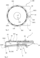
Fig. 3 is a view from below of a protective cover and a ventilation arrangement according to an example embodiment of the present invention, -
Fig. 4 is a perspective and sectional view of a protective cover according to an example embodiment of the present invention, -
Fig. 5 is a perspective view of a battery housing according to an example embodiment of the present invention, -
Fig. 6 is a side view of a vehicle according to an example embodiment of the present invention, and -
Fig. 7 show schematic views of protective covers according to example embodiments of the present invention. - The drawings are schematic and not necessarily drawn to scale. It shall be understood that the embodiments shown and described are exemplifying and that the disclosure is not limited to these embodiments. It shall also be noted that some details in the drawings may be exaggerated in order to better describe and illustrate the disclosure. Like reference characters throughout the drawings refer to the same, or similar, type of element unless expressed otherwise.
-
Fig. 1 depicts a perspective view of aprotective cover 1 according to an example embodiment of the present invention.Fig. 2 depicts theprotective cover 1 infig. 1 when it is provided on aventilation device 110. Accordingly,fig. 2 also shows a ventilation arrangement 100 according to an example embodiment of the invention.Fig. 2 shows a cross-sectional view, the cross-section being defined by a plane including an axis A. The axis A corresponds to a rotational axis of theprotective cover 1 and to an axial direction of theprotective cover 1. - The
protective cover 1 is intended to protect theventilation device 110 during use. Theventilation device 110 is intended to be provided on abattery housing 1000, for example thebattery housing 1000 as shown infig. 5 . - The
ventilation device 110 comprises anairflow opening 102 which is arranged to provide an airflow between an inside of thebattery housing 1000 and an external environment. As shown infig. 2 , theairflow opening 102 may also extend along the axis A, i.e. the axis A may also represent a main flow direction of theairflow opening 102. In addition, thebattery housing 1000 and/or theventilation device 110 comprises afirst flange portion 104 which extends around theairflow opening 102, and which further extends in a radially outward direction with respect to theairflow opening 102. Accordingly, thefirst flange portion 104 extends radially outwardly with respect to the axis A. In the embodiment shown infig. 2 , theventilation device 110 comprises thefirst flange portion 104. - The
protective cover 1 comprises anairflow duct 10 extending between afirst opening 12 and asecond opening 14. Thefirst opening 12 of theairflow duct 10 is arranged to be fluidly connected to theairflow opening 102 of theventilation device 110 and thesecond opening 14 is arranged to be fluidly connected to the external environment. By fluidly connected means herein that a connection for fluid, typically air, is provided. In other words, fluid, typically air, can thereby pass between thefirst opening 12 and theairflow opening 102, and between thesecond opening 14 and the external environment. - The
protective cover 1 further comprises anattachment portion 20 which is associated with thefirst opening 12 for attaching theprotective cover 1 to thefirst flange portion 104 so that theprotective cover 1 covers theairflow opening 102. In the embodiment shown infigs. 1 and 2 , theattachment portion 20 defines thefirst opening 10. When theattachment portion 20 is attached to thefirst flange portion 104, it extends around theairflow opening 102. - The
first flange portion 104 is in this example extending continuously around theairflow opening 102, i.e. it may for example be disc-shaped. However, it shall be noted that the first flange portion may in other embodiments extend around the airflow opening in a noncontinuous manner. For example, it may be formed by a plurality of radially extending protrusions (not shown) with intermediate recesses in-between the protrusions, such as forming a number of teeth-formed elements provided around theairflow opening 102. - The
protective cover 1 further comprises at least twoseparate parts attachment portion 20 can be split into at least twoseparate attachment sections protective cover 1 to be attached to and released from thefirst flange portion 102. - As shown in the embodiment of
figs. 1 and 2 , theprotective cover 1 may be split along a plane which includes the axis A. - As further shown, the at least two
separate parts airflow duct 10 when being attached to each other. Accordingly, the at least twoseparate parts protective cover 1 which are releasably attachable to each other. - As further depicted in e.g.
figs. 1 and 2 , theattachment portion 20 may comprise a second and athird flange portion attachment portion 20, and which further extend in a radially inward direction thereof, corresponding to the radial direction of theairflow opening 102 when theprotective cover 1 is attached to thefirst flange 102. In addition, the second and thethird flange portions protective cover 1, the axial direction A being perpendicular to the radial direction of theprotective cover 1, thereby forming a gap therebetween so that thefirst flange portion 102 can be accommodated in-between the second and thethird flange portions - As further depicted, the
second flange portion 26 may compriseprotrusions 262 which extend in the radially inward direction, i.e. towards the axis A, wherein theprotrusions 262 are separated by intermediate recesses which extend radially outward so as to allow theprotective cover 1 to be attached to thefirst flange portion 102 in more than one predefined angular position with respect to thefirst flange portion 102. As shown, theprotrusions 262 may be formed as teeth, such as teeth with sharp edges, for example triangular shaped protrusions. Additionally, or alternatively, the protrusions may be formed as smooth outwardly bulging protrusions, such as curved-shaped portions. - For example, as shown, the inner perimeter surface of the
attachment portion 20 and/or of thefirst airflow opening 12 is/are annular, i.e. circular. This for example enables theprotective cover 1 to be rotated with respect to the axis A before it is firmly attached to theventilation device 110. -
Fig. 4 depicts onehalf 40 of the two separate parts as shown in e.g.fig 1 . As shown, theairflow duct 10 may comprise a firstairflow duct extension 16 associated with thefirst opening 12 and a secondairflow duct extension 18 associated with thesecond opening 14. The firstairflow duct extension 16 extends in the axial direction A of theprotective cover 1, corresponding to the axial direction of theairflow opening 102 when theprotective cover 1 is attached to thefirst flange portion 104. The secondairflow duct extension 18 is angled with respect to the firstairflow duct extension 16, in this example angled so that the secondairflow duct extension 18 extends substantially in the radial direction. In other words, theprotective cover 1 is in this example formed so that theairflow duct 10 is bent by an angle α, which in this example is 90 degrees. Other angles α are also feasible, such as a bending angle α between the two extensions in the range of 30-120 degrees. - As further depicted in e.g.
fig. 2 andfig 4 , the at least twoseparate parts separate parts connection 32 may comprise two corresponding apertures on eachseparate part - Additionally, or alternatively, the at least two
separate parts separate parts fig. 1 , the protective cover may comprise an outerperipheral surface 324, in this example an annular outer peripheral surface, which is associated with theattachment portion 20. In the shown embodiment, the outerperipheral surface 324 is provided radially outside theattachment portion 20. The outerperipheral surface 324 is adapted to receive a cable tie so that theattachment portion 20 is clamped to thefirst flange portion 104. Still optionally, as further shown in e.g.fig. 1 , at least one firstradially protruding portion 3241 may be associated with the outerperipheral surface 324 and arranged to align the cable tie on the outerperipheral surface 324 during use. In the shown example, the firstradially protruding portion 3241 is provided adjacent the outerperipheral surface 324, in this example axially above the outerperipheral surface 324. By the at least one firstradially protruding portion 3241, unintentional release of the cable tie can be avoided, i.e. the cable tie is prevented from moving upwardly in the axial direction, i.e. in a direction corresponding the axis A. Additionally, or alternatively, as further shown, at least one secondradially protruding portion 3242 may be associated with the outerperipheral surface 324 and arranged to align the cable tie on the outerperipheral surface 324 during use. In the shown example, the secondradially protruding portion 3242 is provided adjacent the outerperipheral surface 324, in this example axially below the outerperipheral surface 324. - The
protective cover 1 may further comprise a sealing member (not shown) which is provided in an attachment interface in-between the at least twoseparate parts - As further depicted in e.g.
fig. 2 , the at least twoseparate parts separate parts separate parts separate parts 40 forms a seat surface for the other portion 34 of the otherseparate part 30, wherein the other portion 34 is received on the seat surface 44. -
Fig. 3 depicts the ventilation arrangement 100 from below. - The ventilation arrangement 100 comprises the
ventilation device 110. Theventilation device 110 is arranged to provide an airflow through theairflow opening 102 between an inside of thebattery housing 1000 and an external environment. The ventilation arrangement 100 further comprises theprotective cover 1. - As shown, the
first flange portion 104 may comprises correspondingprotrusions 1041 which are configured to be in meshing engagement with theprotrusions 262 of thesecond flange portion 26. The correspondingprotrusions 1041 are here facing downwardly and away from thefirst flange portion 104. Thefirst flange portion 104 is partly concealed infig. 3 by theprotrusions 262 of theprotective cover 1. - As further shown, the
attachment portion 20 may comprise one or more spring-biasingmembers 2621 which are configured to exert a force in a radial direction on theventilation device 110. In the shown example, the spring-biasingmembers 2621 are in the form of elongated pins extending substantially in a tangential direction of the inner perimeter surface of theattachment portion 20. The spring-biasingmembers 2621 are elastic so that they can flex outwardly and/or inwardly towards and/or away from the axis A. Additionally, or alternatively, theventilation device 110 may comprise spring-biasing members (not shown) which are configured to exert a force in a radial direction on theprotective cover 1. By the spring-biasingmembers 2621, an improved and more reliable attachment between theprotective cover 1 and theventilation device 110 can be achieved. For example, by said spring-biasingmembers 2621, the risk of unwanted vibrations can be reduced. -
Fig. 5 depicts an example of abattery housing 1000 in perspective view. Thebattery housing 1000 comprises a ventilation arrangement 100 as e.g. shown infig. 2 . Accordingly, as shown in this example, twoprotective covers 1 are provided on respective ventilation devices 110 (not shown infig. 5 ) of thebattery housing 1000. The direction of the axis A of each respectiveprotective cover 1 is in this embodiment corresponding to an extension of a normal of asurface 1100 on which therespective ventilation device 110 is provided. -
Fig. 6 depicts a side view of avehicle 200 comprising abattery housing 1000 according to the invention. Thevehicle 200 is in this example a truck, more specifically a towing truck. Thetruck 200 is configured to be driven by one or more electric motors (not shown) which are powered by a battery unit (not shown). The battery unit is provided inside thebattery housing 1000. The one or more electric motors are configured to drivewheels 210, or any other type of ground engaging means, of thevehicle 200. It shall be noted that the vehicle may be any other type of vehicle as for example disclosed herein. -
Figs. 7a-c show schematic views from above of respectiveprotective covers 1 according to example embodiments of the invention. The embodiments depict that thesecond opening 14 can have different shapes. The different shapes may for example as shown be noticed when viewing theprotective cover 1 from above, i.e. in a view directed along the axis A. As shown infig. 7a , an outer peripheral portion of theprotective cover 1 defining thesecond opening 14 may be angled with respect to a main flow direction F of an airflow passing thesecond opening 14.Fig. 7b shows another example where an outer peripheral portion of theprotective cover 1 defining thesecond opening 14 comprises respective chamfered sections at respective corner portions of thesecond opening 14.Fig. 7c shows yet another example where an outer peripheral portion of theprotective cover 1 defining thesecond opening 14 is formed by two angled sections which together form a tip pointing away from theprotective cover 1 in a radial direction with respect to the axis A. It has been found that it may be advantageous if the outer peripheral portion of theprotective cover 1 defining thesecond opening 14 has an irregular shape. Thereby, the risk of ice getting stuck at the second opening during use may be reduced. More particularly, by the irregular shape, i.e. in contrast to a straight cut which is perpendicular to the main flow direction F of the airflow passing thesecond opening 14, a rattling or vibrating effect may be accomplished at the outer peripheral portion defining thesecond opening 14. This effect may reduce the risk of ice getting stuck at thesecond opening 14 during use in cold conditions. - It is to be understood that the present invention is not limited to the embodiments described above and illustrated in the drawings; rather, the skilled person will recognize that many changes and modifications may be made within the scope of the appended claims.
Claims (15)
- A protective cover (1) for protecting a ventilation device (110) of a battery housing (1000), wherein the ventilation device (110) comprises an airflow opening (102) which is arranged to provide an airflow between an inside of the battery housing (1000) and an external environment, and wherein the battery housing (1000) and/or the ventilation device (110) comprises a first flange portion (104) which extends around the airflow opening (102), and which further extends in a radially outward direction with respect to the airflow opening (102),
the protective cover (1) comprising:- an airflow duct (10) extending between a first opening (12) and a second opening (14), wherein the first opening (12) of the airflow duct (10) is arranged to be fluidly connected to the airflow opening (102) of the ventilation device (110) and wherein the second opening (14) is arranged to be fluidly connected to the external environment,- an attachment portion (20) associated with the first opening (12) for attaching the protective cover (1) to the first flange portion (104) so that the protective cover (1) covers the airflow opening (102), wherein the attachment portion (20), when being attached to the first flange portion (104), extends around the airflow opening (102),- wherein the protective cover (1) comprises at least two separate parts (30, 40) which are releasably attachable to each other and arranged so that the attachment portion (20) can be split into at least two separate attachment sections (22, 24) to allow the protective cover (1) to be attached to and released from the first flange portion (102). - The protective cover (1) according to claim 1, wherein the at least two separate parts (30, 40) are further arranged to form the airflow duct (10) when being attached to each other.
- The protective cover (1) according to any one of the preceding claims, wherein the at least two separate parts (30, 40) are two halves of the protective cover (1) which are releasably attachable to each other.
- The protective cover (1) according to any one of the preceding claims, wherein the attachment portion (20) comprises a second and a third flange portion (26, 28) which extend around an inner perimeter surface of the attachment portion (20), and which further extend in a radially inward direction thereof, corresponding to the radial direction of the airflow opening (102) when the protective cover (1) is attached to the first flange portion (104), and wherein the second and the third flange portions (26, 28) are offset from each other, as seen in an axial direction (A) of the protective cover (1), the axial direction (A) being perpendicular to the radial direction of the protective cover (1), thereby forming a gap therebetween so that the first flange portion (104) can be accommodated in-between the second and the third flange portions (26, 28).
- The protective cover (1) according to claim 4, wherein the second flange portion (26) comprises protrusions (262) which extend in the radially inward direction, wherein the protrusions are separated by intermediate recesses which extend radially outward so as to allow the protective cover (1) to be attached to the first flange portion (104) in more than one predefined angular position with respect to the first flange portion (104).
- The protective cover (1) according to claim 5, wherein the protrusions are formed as teeth, such as teeth with sharp edges, for example triangular shaped protrusions, and/or as smooth outwardly bulging protrusions, such as curved-shaped portions.
- The protective cover (1) according to any one of the preceding claims, wherein the airflow duct (10) comprises a first airflow duct extension (16) associated with the first opening (12) and a second airflow duct extension (18) associated with the second opening (14), wherein the first airflow duct extension (16) extends in an axial direction (A) of the protective cover (1), corresponding to an axial direction of the airflow opening (102) when the protective cover (1) is attached to the first flange portion (104), and wherein the second airflow duct extension (18) is angled with respect to the first airflow duct extension (16), such as angled so that the second airflow duct extension (18) extends substantially in the radial direction.
- The protective cover (1) according to any one of the preceding claims, wherein the at least two separate parts (30, 40) further comprises fastening means (32) for attaching the at least two separate parts (30, 40) to each other.
- The protective cover (1) according to claim 8, wherein the fastening means comprises any one of a screw, a bolt, a nut, a cable tie and a snap-fit connection member, such as a clip member.
- The protective cover (1) according to any one of the preceding claims, further comprising a sealing member provided in an attachment interface in-between the at least two separate parts.
- The protective cover (1) according to any one of the preceding claims, wherein the at least two separate parts (30, 40) are arranged so that respective portions (34, 44) thereof overlap each other when the at least two separate parts (30, 40) are attached to each other.
- A ventilation arrangement (100) for a battery housing (1000), comprising a ventilation device (110), wherein the ventilation device (110) is arranged to provide an airflow through an airflow opening (102) between an inside of the battery housing (1000) and an external environment, and wherein the battery housing (1000) and/or the ventilation device (110) comprises a first flange portion (104) which extends around the airflow opening (102), and which further extends in a radially outward direction with respect to the airflow opening (102), and wherein the ventilation arrangement further comprises a protective cover (1) according to any one of the preceding claims.
- The ventilation arrangement (100) according to claim 12, when also being dependent on claim 5, wherein the first flange portion (104) comprises corresponding protrusions () configured to be in meshing engagement with the protrusions (262) of the second flange portion (26).
- A battery housing (1000) comprising a ventilation arrangement (100) according to claim 12 or 13.
- A vehicle (200) comprising a battery housing (1000) according to claim 14.
Priority Applications (2)
| Application Number | Priority Date | Filing Date | Title |
|---|---|---|---|
| EP22183387.4A EP4303993B1 (en) | 2022-07-06 | 2022-07-06 | A protective cover for protecting a ventilation device of a battery housing |
| US18/343,518 US20240014508A1 (en) | 2022-07-06 | 2023-06-28 | Protective cover for protecting a ventilation device of a battery housing |
Applications Claiming Priority (1)
| Application Number | Priority Date | Filing Date | Title |
|---|---|---|---|
| EP22183387.4A EP4303993B1 (en) | 2022-07-06 | 2022-07-06 | A protective cover for protecting a ventilation device of a battery housing |
Publications (2)
| Publication Number | Publication Date |
|---|---|
| EP4303993A1 true EP4303993A1 (en) | 2024-01-10 |
| EP4303993B1 EP4303993B1 (en) | 2025-08-27 |
Family
ID=82399569
Family Applications (1)
| Application Number | Title | Priority Date | Filing Date |
|---|---|---|---|
| EP22183387.4A Active EP4303993B1 (en) | 2022-07-06 | 2022-07-06 | A protective cover for protecting a ventilation device of a battery housing |
Country Status (2)
| Country | Link |
|---|---|
| US (1) | US20240014508A1 (en) |
| EP (1) | EP4303993B1 (en) |
Citations (7)
| Publication number | Priority date | Publication date | Assignee | Title |
|---|---|---|---|---|
| JPH09245768A (en) * | 1996-03-12 | 1997-09-19 | Toyota Autom Loom Works Ltd | Battery terminal cover |
| EP0915525A1 (en) * | 1997-11-04 | 1999-05-12 | Olimpio Stocchiero | Cover for polar element for the lid of a battery |
| US7951474B2 (en) * | 2005-03-10 | 2011-05-31 | Abertax Reserach & Development Ltd | Gas release valve |
| GB2517468A (en) * | 2013-08-21 | 2015-02-25 | Jaguar Land Rover Ltd | Vent apparatus for a battery casing |
| US20160036025A1 (en) * | 2014-08-04 | 2016-02-04 | Lisa Draexlmaier Gmbh | Degassing valve |
| EP3477756A1 (en) * | 2017-10-30 | 2019-05-01 | Samsung SDI Co., Ltd. | Ventilation device for a battery |
| US20220112962A1 (en) * | 2020-10-12 | 2022-04-14 | Donaldson Company, Inc. | Enclosure vent assembly |
-
2022
- 2022-07-06 EP EP22183387.4A patent/EP4303993B1/en active Active
-
2023
- 2023-06-28 US US18/343,518 patent/US20240014508A1/en active Pending
Patent Citations (7)
| Publication number | Priority date | Publication date | Assignee | Title |
|---|---|---|---|---|
| JPH09245768A (en) * | 1996-03-12 | 1997-09-19 | Toyota Autom Loom Works Ltd | Battery terminal cover |
| EP0915525A1 (en) * | 1997-11-04 | 1999-05-12 | Olimpio Stocchiero | Cover for polar element for the lid of a battery |
| US7951474B2 (en) * | 2005-03-10 | 2011-05-31 | Abertax Reserach & Development Ltd | Gas release valve |
| GB2517468A (en) * | 2013-08-21 | 2015-02-25 | Jaguar Land Rover Ltd | Vent apparatus for a battery casing |
| US20160036025A1 (en) * | 2014-08-04 | 2016-02-04 | Lisa Draexlmaier Gmbh | Degassing valve |
| EP3477756A1 (en) * | 2017-10-30 | 2019-05-01 | Samsung SDI Co., Ltd. | Ventilation device for a battery |
| US20220112962A1 (en) * | 2020-10-12 | 2022-04-14 | Donaldson Company, Inc. | Enclosure vent assembly |
Also Published As
| Publication number | Publication date |
|---|---|
| US20240014508A1 (en) | 2024-01-11 |
| EP4303993B1 (en) | 2025-08-27 |
Similar Documents
| Publication | Publication Date | Title |
|---|---|---|
| US6056297A (en) | Intermediate shaft dash panel seal | |
| US8523447B2 (en) | Wheel bearing arrangement having gasket | |
| US20110170817A1 (en) | Device for axial fixation | |
| EP2454145B1 (en) | Steering robot | |
| EP3237158B1 (en) | Fastener retention device for a guard cover | |
| US5503189A (en) | Flange protector having flexible coupling insert and method for detachably coupling same to a conduit | |
| US20080292231A1 (en) | Sealing Device | |
| JP2018046704A (en) | Grommet mounting structure | |
| US8196625B1 (en) | Supplemental tread tire bead lock | |
| TW201206764A (en) | Vehicle provided with a driving motor | |
| EP4303993B1 (en) | A protective cover for protecting a ventilation device of a battery housing | |
| US20120129615A1 (en) | Cardan joint assembly and a cardan joint protector device | |
| CN101351654A (en) | Direct Torque Flow Constant Velocity Joint with Collet Connection | |
| JP2003527271A (en) | Component unit for supporting and drivingly coupling wheels | |
| EP1418066A2 (en) | Supporting structure of axle hub | |
| US11273671B2 (en) | Axle differential guard | |
| US12553475B2 (en) | Conductive assembly with reinforced base plate | |
| JPH0996319A (en) | Flexible boot for constant velocity joint | |
| EP1900545A1 (en) | Aircraft wheel noise reduction fairing and aircraft wheel including a noise reduction fairing | |
| US11156484B2 (en) | Vehicle sensor armor system | |
| CN113479260B (en) | Automobile and arm hanging mechanism thereof | |
| KR102647519B1 (en) | Wheel tread vairable axle assembly for agricultural working vehicle | |
| CN210461619U (en) | Protective structure of drive axle main reducer and drive axle main reducer | |
| JPH09132002A (en) | Anti-corrosion cover mounting structure | |
| US11365766B2 (en) | Protective covering |
Legal Events
| Date | Code | Title | Description |
|---|---|---|---|
| PUAI | Public reference made under article 153(3) epc to a published international application that has entered the european phase |
Free format text: ORIGINAL CODE: 0009012 |
|
| STAA | Information on the status of an ep patent application or granted ep patent |
Free format text: STATUS: THE APPLICATION HAS BEEN PUBLISHED |
|
| AK | Designated contracting states |
Kind code of ref document: A1 Designated state(s): AL AT BE BG CH CY CZ DE DK EE ES FI FR GB GR HR HU IE IS IT LI LT LU LV MC MK MT NL NO PL PT RO RS SE SI SK SM TR |
|
| STAA | Information on the status of an ep patent application or granted ep patent |
Free format text: STATUS: REQUEST FOR EXAMINATION WAS MADE |
|
| 17P | Request for examination filed |
Effective date: 20240701 |
|
| RBV | Designated contracting states (corrected) |
Designated state(s): AL AT BE BG CH CY CZ DE DK EE ES FI FR GB GR HR HU IE IS IT LI LT LU LV MC MK MT NL NO PL PT RO RS SE SI SK SM TR |
|
| STAA | Information on the status of an ep patent application or granted ep patent |
Free format text: STATUS: EXAMINATION IS IN PROGRESS |
|
| 17Q | First examination report despatched |
Effective date: 20241021 |
|
| GRAP | Despatch of communication of intention to grant a patent |
Free format text: ORIGINAL CODE: EPIDOSNIGR1 |
|
| STAA | Information on the status of an ep patent application or granted ep patent |
Free format text: STATUS: GRANT OF PATENT IS INTENDED |
|
| INTG | Intention to grant announced |
Effective date: 20250220 |
|
| GRAS | Grant fee paid |
Free format text: ORIGINAL CODE: EPIDOSNIGR3 |
|
| GRAA | (expected) grant |
Free format text: ORIGINAL CODE: 0009210 |
|
| STAA | Information on the status of an ep patent application or granted ep patent |
Free format text: STATUS: THE PATENT HAS BEEN GRANTED |
|
| AK | Designated contracting states |
Kind code of ref document: B1 Designated state(s): AL AT BE BG CH CY CZ DE DK EE ES FI FR GB GR HR HU IE IS IT LI LT LU LV MC MK MT NL NO PL PT RO RS SE SI SK SM TR |
|
| REG | Reference to a national code |
Ref country code: CH Ref legal event code: EP |
|
| REG | Reference to a national code |
Ref country code: DE Ref legal event code: R096 Ref document number: 602022020102 Country of ref document: DE |
|
| REG | Reference to a national code |
Ref country code: IE Ref legal event code: FG4D |
|
| REG | Reference to a national code |
Ref country code: NL Ref legal event code: MP Effective date: 20250827 |
|
| PG25 | Lapsed in a contracting state [announced via postgrant information from national office to epo] |
Ref country code: IS Free format text: LAPSE BECAUSE OF FAILURE TO SUBMIT A TRANSLATION OF THE DESCRIPTION OR TO PAY THE FEE WITHIN THE PRESCRIBED TIME-LIMIT Effective date: 20251227 |
|
| PG25 | Lapsed in a contracting state [announced via postgrant information from national office to epo] |
Ref country code: NO Free format text: LAPSE BECAUSE OF FAILURE TO SUBMIT A TRANSLATION OF THE DESCRIPTION OR TO PAY THE FEE WITHIN THE PRESCRIBED TIME-LIMIT Effective date: 20251127 |
|
| REG | Reference to a national code |
Ref country code: LT Ref legal event code: MG9D |
|
| PG25 | Lapsed in a contracting state [announced via postgrant information from national office to epo] |
Ref country code: PT Free format text: LAPSE BECAUSE OF FAILURE TO SUBMIT A TRANSLATION OF THE DESCRIPTION OR TO PAY THE FEE WITHIN THE PRESCRIBED TIME-LIMIT Effective date: 20251229 |
|
| PG25 | Lapsed in a contracting state [announced via postgrant information from national office to epo] |
Ref country code: FI Free format text: LAPSE BECAUSE OF FAILURE TO SUBMIT A TRANSLATION OF THE DESCRIPTION OR TO PAY THE FEE WITHIN THE PRESCRIBED TIME-LIMIT Effective date: 20250827 |
|
| PG25 | Lapsed in a contracting state [announced via postgrant information from national office to epo] |
Ref country code: HR Free format text: LAPSE BECAUSE OF FAILURE TO SUBMIT A TRANSLATION OF THE DESCRIPTION OR TO PAY THE FEE WITHIN THE PRESCRIBED TIME-LIMIT Effective date: 20250827 Ref country code: NL Free format text: LAPSE BECAUSE OF FAILURE TO SUBMIT A TRANSLATION OF THE DESCRIPTION OR TO PAY THE FEE WITHIN THE PRESCRIBED TIME-LIMIT Effective date: 20250827 |
|
| PG25 | Lapsed in a contracting state [announced via postgrant information from national office to epo] |
Ref country code: GR Free format text: LAPSE BECAUSE OF FAILURE TO SUBMIT A TRANSLATION OF THE DESCRIPTION OR TO PAY THE FEE WITHIN THE PRESCRIBED TIME-LIMIT Effective date: 20251128 |
|
| PG25 | Lapsed in a contracting state [announced via postgrant information from national office to epo] |
Ref country code: SE Free format text: LAPSE BECAUSE OF FAILURE TO SUBMIT A TRANSLATION OF THE DESCRIPTION OR TO PAY THE FEE WITHIN THE PRESCRIBED TIME-LIMIT Effective date: 20250827 |
|
| PG25 | Lapsed in a contracting state [announced via postgrant information from national office to epo] |
Ref country code: LV Free format text: LAPSE BECAUSE OF FAILURE TO SUBMIT A TRANSLATION OF THE DESCRIPTION OR TO PAY THE FEE WITHIN THE PRESCRIBED TIME-LIMIT Effective date: 20250827 |
|
| PG25 | Lapsed in a contracting state [announced via postgrant information from national office to epo] |
Ref country code: BG Free format text: LAPSE BECAUSE OF FAILURE TO SUBMIT A TRANSLATION OF THE DESCRIPTION OR TO PAY THE FEE WITHIN THE PRESCRIBED TIME-LIMIT Effective date: 20250827 Ref country code: PL Free format text: LAPSE BECAUSE OF FAILURE TO SUBMIT A TRANSLATION OF THE DESCRIPTION OR TO PAY THE FEE WITHIN THE PRESCRIBED TIME-LIMIT Effective date: 20250827 |
|
| PG25 | Lapsed in a contracting state [announced via postgrant information from national office to epo] |
Ref country code: RS Free format text: LAPSE BECAUSE OF FAILURE TO SUBMIT A TRANSLATION OF THE DESCRIPTION OR TO PAY THE FEE WITHIN THE PRESCRIBED TIME-LIMIT Effective date: 20251127 |
|
| PG25 | Lapsed in a contracting state [announced via postgrant information from national office to epo] |
Ref country code: ES Free format text: LAPSE BECAUSE OF FAILURE TO SUBMIT A TRANSLATION OF THE DESCRIPTION OR TO PAY THE FEE WITHIN THE PRESCRIBED TIME-LIMIT Effective date: 20250827 |
|
| REG | Reference to a national code |
Ref country code: AT Ref legal event code: MK05 Ref document number: 1831097 Country of ref document: AT Kind code of ref document: T Effective date: 20250827 |
|
| PG25 | Lapsed in a contracting state [announced via postgrant information from national office to epo] |
Ref country code: SM Free format text: LAPSE BECAUSE OF FAILURE TO SUBMIT A TRANSLATION OF THE DESCRIPTION OR TO PAY THE FEE WITHIN THE PRESCRIBED TIME-LIMIT Effective date: 20250827 |
|
| PG25 | Lapsed in a contracting state [announced via postgrant information from national office to epo] |
Ref country code: DK Free format text: LAPSE BECAUSE OF FAILURE TO SUBMIT A TRANSLATION OF THE DESCRIPTION OR TO PAY THE FEE WITHIN THE PRESCRIBED TIME-LIMIT Effective date: 20250827 |
|
| PG25 | Lapsed in a contracting state [announced via postgrant information from national office to epo] |
Ref country code: AT Free format text: LAPSE BECAUSE OF FAILURE TO SUBMIT A TRANSLATION OF THE DESCRIPTION OR TO PAY THE FEE WITHIN THE PRESCRIBED TIME-LIMIT Effective date: 20250827 |
|
| PG25 | Lapsed in a contracting state [announced via postgrant information from national office to epo] |
Ref country code: IT Free format text: LAPSE BECAUSE OF FAILURE TO SUBMIT A TRANSLATION OF THE DESCRIPTION OR TO PAY THE FEE WITHIN THE PRESCRIBED TIME-LIMIT Effective date: 20250827 |
|
| PG25 | Lapsed in a contracting state [announced via postgrant information from national office to epo] |
Ref country code: CZ Free format text: LAPSE BECAUSE OF FAILURE TO SUBMIT A TRANSLATION OF THE DESCRIPTION OR TO PAY THE FEE WITHIN THE PRESCRIBED TIME-LIMIT Effective date: 20250827 |
|
| PG25 | Lapsed in a contracting state [announced via postgrant information from national office to epo] |
Ref country code: SK Free format text: LAPSE BECAUSE OF FAILURE TO SUBMIT A TRANSLATION OF THE DESCRIPTION OR TO PAY THE FEE WITHIN THE PRESCRIBED TIME-LIMIT Effective date: 20250827 Ref country code: EE Free format text: LAPSE BECAUSE OF FAILURE TO SUBMIT A TRANSLATION OF THE DESCRIPTION OR TO PAY THE FEE WITHIN THE PRESCRIBED TIME-LIMIT Effective date: 20250827 |