EP4303983A1 - Electrochemical device, electrochemical device assembly, and electronic device - Google Patents
Electrochemical device, electrochemical device assembly, and electronic device Download PDFInfo
- Publication number
- EP4303983A1 EP4303983A1 EP23183764.2A EP23183764A EP4303983A1 EP 4303983 A1 EP4303983 A1 EP 4303983A1 EP 23183764 A EP23183764 A EP 23183764A EP 4303983 A1 EP4303983 A1 EP 4303983A1
- Authority
- EP
- European Patent Office
- Prior art keywords
- electrochemical device
- housing
- polymer layer
- area
- metal layer
- Prior art date
- Legal status (The legal status is an assumption and is not a legal conclusion. Google has not performed a legal analysis and makes no representation as to the accuracy of the status listed.)
- Pending
Links
Images



Classifications
-
- H—ELECTRICITY
- H01—ELECTRIC ELEMENTS
- H01M—PROCESSES OR MEANS, e.g. BATTERIES, FOR THE DIRECT CONVERSION OF CHEMICAL ENERGY INTO ELECTRICAL ENERGY
- H01M50/00—Constructional details or processes of manufacture of the non-active parts of electrochemical cells other than fuel cells, e.g. hybrid cells
- H01M50/10—Primary casings; Jackets or wrappings
- H01M50/102—Primary casings; Jackets or wrappings characterised by their shape or physical structure
- H01M50/105—Pouches or flexible bags
-
- H—ELECTRICITY
- H01—ELECTRIC ELEMENTS
- H01M—PROCESSES OR MEANS, e.g. BATTERIES, FOR THE DIRECT CONVERSION OF CHEMICAL ENERGY INTO ELECTRICAL ENERGY
- H01M10/00—Secondary cells; Manufacture thereof
- H01M10/05—Accumulators with non-aqueous electrolyte
- H01M10/052—Li-accumulators
- H01M10/0525—Rocking-chair batteries, i.e. batteries with lithium insertion or intercalation in both electrodes; Lithium-ion batteries
-
- H—ELECTRICITY
- H01—ELECTRIC ELEMENTS
- H01M—PROCESSES OR MEANS, e.g. BATTERIES, FOR THE DIRECT CONVERSION OF CHEMICAL ENERGY INTO ELECTRICAL ENERGY
- H01M10/00—Secondary cells; Manufacture thereof
- H01M10/05—Accumulators with non-aqueous electrolyte
- H01M10/054—Accumulators with insertion or intercalation of metals other than lithium, e.g. with magnesium or aluminium
-
- H—ELECTRICITY
- H01—ELECTRIC ELEMENTS
- H01M—PROCESSES OR MEANS, e.g. BATTERIES, FOR THE DIRECT CONVERSION OF CHEMICAL ENERGY INTO ELECTRICAL ENERGY
- H01M10/00—Secondary cells; Manufacture thereof
- H01M10/42—Methods or arrangements for servicing or maintenance of secondary cells or secondary half-cells
- H01M10/46—Accumulators structurally combined with charging apparatus
-
- H—ELECTRICITY
- H01—ELECTRIC ELEMENTS
- H01M—PROCESSES OR MEANS, e.g. BATTERIES, FOR THE DIRECT CONVERSION OF CHEMICAL ENERGY INTO ELECTRICAL ENERGY
- H01M10/00—Secondary cells; Manufacture thereof
- H01M10/60—Heating or cooling; Temperature control
- H01M10/61—Types of temperature control
- H01M10/613—Cooling or keeping cold
-
- H—ELECTRICITY
- H01—ELECTRIC ELEMENTS
- H01M—PROCESSES OR MEANS, e.g. BATTERIES, FOR THE DIRECT CONVERSION OF CHEMICAL ENERGY INTO ELECTRICAL ENERGY
- H01M10/00—Secondary cells; Manufacture thereof
- H01M10/60—Heating or cooling; Temperature control
- H01M10/64—Heating or cooling; Temperature control characterised by the shape of the cells
- H01M10/647—Prismatic or flat cells, e.g. pouch cells
-
- H—ELECTRICITY
- H01—ELECTRIC ELEMENTS
- H01M—PROCESSES OR MEANS, e.g. BATTERIES, FOR THE DIRECT CONVERSION OF CHEMICAL ENERGY INTO ELECTRICAL ENERGY
- H01M10/00—Secondary cells; Manufacture thereof
- H01M10/60—Heating or cooling; Temperature control
- H01M10/65—Means for temperature control structurally associated with the cells
- H01M10/653—Means for temperature control structurally associated with the cells characterised by electrically insulating or thermally conductive materials
-
- H—ELECTRICITY
- H01—ELECTRIC ELEMENTS
- H01M—PROCESSES OR MEANS, e.g. BATTERIES, FOR THE DIRECT CONVERSION OF CHEMICAL ENERGY INTO ELECTRICAL ENERGY
- H01M10/00—Secondary cells; Manufacture thereof
- H01M10/60—Heating or cooling; Temperature control
- H01M10/65—Means for temperature control structurally associated with the cells
- H01M10/655—Solid structures for heat exchange or heat conduction
-
- H—ELECTRICITY
- H01—ELECTRIC ELEMENTS
- H01M—PROCESSES OR MEANS, e.g. BATTERIES, FOR THE DIRECT CONVERSION OF CHEMICAL ENERGY INTO ELECTRICAL ENERGY
- H01M50/00—Constructional details or processes of manufacture of the non-active parts of electrochemical cells other than fuel cells, e.g. hybrid cells
- H01M50/10—Primary casings; Jackets or wrappings
- H01M50/116—Primary casings; Jackets or wrappings characterised by the material
- H01M50/117—Inorganic material
- H01M50/119—Metals
-
- H—ELECTRICITY
- H01—ELECTRIC ELEMENTS
- H01M—PROCESSES OR MEANS, e.g. BATTERIES, FOR THE DIRECT CONVERSION OF CHEMICAL ENERGY INTO ELECTRICAL ENERGY
- H01M50/00—Constructional details or processes of manufacture of the non-active parts of electrochemical cells other than fuel cells, e.g. hybrid cells
- H01M50/10—Primary casings; Jackets or wrappings
- H01M50/116—Primary casings; Jackets or wrappings characterised by the material
- H01M50/121—Organic material
-
- H—ELECTRICITY
- H01—ELECTRIC ELEMENTS
- H01M—PROCESSES OR MEANS, e.g. BATTERIES, FOR THE DIRECT CONVERSION OF CHEMICAL ENERGY INTO ELECTRICAL ENERGY
- H01M50/00—Constructional details or processes of manufacture of the non-active parts of electrochemical cells other than fuel cells, e.g. hybrid cells
- H01M50/10—Primary casings; Jackets or wrappings
- H01M50/116—Primary casings; Jackets or wrappings characterised by the material
- H01M50/124—Primary casings; Jackets or wrappings characterised by the material having a layered structure
- H01M50/1243—Primary casings; Jackets or wrappings characterised by the material having a layered structure characterised by the internal coating on the casing
-
- H—ELECTRICITY
- H01—ELECTRIC ELEMENTS
- H01M—PROCESSES OR MEANS, e.g. BATTERIES, FOR THE DIRECT CONVERSION OF CHEMICAL ENERGY INTO ELECTRICAL ENERGY
- H01M50/00—Constructional details or processes of manufacture of the non-active parts of electrochemical cells other than fuel cells, e.g. hybrid cells
- H01M50/10—Primary casings; Jackets or wrappings
- H01M50/116—Primary casings; Jackets or wrappings characterised by the material
- H01M50/124—Primary casings; Jackets or wrappings characterised by the material having a layered structure
- H01M50/126—Primary casings; Jackets or wrappings characterised by the material having a layered structure comprising three or more layers
- H01M50/129—Primary casings; Jackets or wrappings characterised by the material having a layered structure comprising three or more layers with two or more layers of only organic material
-
- Y—GENERAL TAGGING OF NEW TECHNOLOGICAL DEVELOPMENTS; GENERAL TAGGING OF CROSS-SECTIONAL TECHNOLOGIES SPANNING OVER SEVERAL SECTIONS OF THE IPC; TECHNICAL SUBJECTS COVERED BY FORMER USPC CROSS-REFERENCE ART COLLECTIONS [XRACs] AND DIGESTS
- Y02—TECHNOLOGIES OR APPLICATIONS FOR MITIGATION OR ADAPTATION AGAINST CLIMATE CHANGE
- Y02E—REDUCTION OF GREENHOUSE GAS [GHG] EMISSIONS, RELATED TO ENERGY GENERATION, TRANSMISSION OR DISTRIBUTION
- Y02E60/00—Enabling technologies; Technologies with a potential or indirect contribution to GHG emissions mitigation
- Y02E60/10—Energy storage using batteries
Definitions
- the present application relates to the technical field of energy storage, in particular to an electrochemical device, an electrochemical device component, and an electronic device.
- An electrochemical device is a device that converts external energy into electric energy and stores the electric energy therein, so as to supply power to external devices (such as portable electronic devices) at the time of need.
- an electrochemical device includes a receiving housing, an electrode assembly received in the receiving housing, and battery tabs.
- the receiving housing defines a receiving cavity for receiving the electrode assembly.
- the electrode assembly includes a first electrode plate, a second electrode plate, and a separator. A polarity of the first electrode plate is opposite to that of the second electrode plate, and the separator is arranged between the first electrode plate and the second electrode plate for separation.
- One end of one of the battery tabs is connected to the first electrode plate, and the other end of the battery tab extends out of the receiving housing; and one end of the other battery tab is connected to the second electrode plate, and the other end of the battery tab extends out of the receiving housing.
- the receiving housing of the electrochemical device generally includes a first polymer layer, a metal layer, and a second polymer layer disposed in a stacking manner.
- the first polymer layer is arranged on one side of the metal layer facing the inside of the receiving housing, and due to the arrangement of the first polymer layer, hot melt packaging of the receiving housing is facilitated.
- the second polymer layer is arranged on the side of the metal layer facing the outside of the receiving housing, so as to reduce the corrosion rate of the metal layer by the external environment.
- an electrode assembly in the operation process of an electrochemical device, may generate a large amount of heat, and the heat may accumulate continuously in a receiving housing, which may cause thermal runaway of the electrochemical device.
- the present application aims to provide an electrochemical device, an electrochemical device component, and an electronic device to reduce the risk of thermal runaway in current electrochemical devices.
- some embodiments of the present application provide an electrochemical device.
- the electrochemical device includes a receiving housing and an electrode assembly.
- the receiving housing includes a first housing and a second housing, the first housing and the second housing are arranged opposite to each other in a thickness direction of the electrochemical device, and together define a receiving cavity.
- the electrode assembly is received in the receiving cavity.
- the first housing includes a first polymer layer, a first metal layer and a second polymer layer disposed in a stacking manner, the first polymer layer is arranged on a side of the first metal layer facing the second housing, the second polymer layer is arranged on a side of the first metal layer facing away from the second housing, and the first polymer layer is provided with a first through slot penetrating in the thickness direction, so that a surface of the first metal layer facing the second housing includes a first area corresponding to the first through slot and a second area provided with the first polymer layer, and the first area is located between the electrode assembly and the second polymer layer.
- the first polymer layer is provided with the first through slot, so that heat generated by the electrode assembly in the operation process may not be blocked by the first polymer layer when transferred to the first through slot, but may be transferred outward through the first metal layer with a high thermal conductivity. Therefore, the electrochemical device provided by some embodiments of the present application can improve the current situation of continuous accumulation of internal heat in the operation process of the electrochemical device, thereby reducing the risk of thermal runaway of the electrochemical device.
- a projection of the electrode assembly on the first metal layer falls within the first area in the thickness direction of the electrochemical device.
- the electrode assembly may be in direct contact with the first area, so that heat generated by the electrode assembly in the operation process may not be blocked by the first polymer layer when transferred to the first through slot, but may be transferred outward through the first metal layer with a high thermal conductivity.
- the first housing further includes a first thermal conductive material layer.
- the first thermal conductive material layer is arranged on a side of the first area facing the first through slot, a thermal conductivity of the first metal layer is ⁇ 1 , a thermal conductivity of the first thermal conductive material layer is ⁇ 3 , and 1.1 ⁇ ⁇ 3 / ⁇ 1 ⁇ 2.5; and the electrode assembly is opposite to the first thermal conductive material layer. Since the thermal conductivity of the first thermal conductive material layer is greater than that of the first metal layer, dissipation of internal heat of the electrochemical device may be accelerated with this arrangement. In some embodiments, 1.5 ⁇ 3 / ⁇ 1 ⁇ 2, so that the bonding effect between the first thermal conductive material layer and the first metal layer may be improved, which is more conducive to the outward conduction of internal heat of the electrochemical device.
- the first housing includes a first cavity part and a first flange part.
- the first cavity part includes a first base portion and a first side portion extending from an edge of the first base portion, the first base portion and the first side portion together define a first concave cavity, and the receiving cavity includes the first concave cavity.
- the first flange part extends outward from one end of the first side portion facing away from the first base portion. The first area is located at the first cavity part, the second area is located at the first flange part, or the first area is located at the first base portion, and the second area is located at the first side portion and the first flange part.
- the second housing includes a third polymer layer, a second metal layer and a fourth polymer layer disposed in a stacking manner, the third polymer layer is disposed on a side of the second metal layer facing the first housing, and the fourth polymer layer is disposed on a side of the second metal layer facing away from the first housing.
- the third polymer layer is provided with a second through slot penetrating in the thickness direction, a surface of the second metal layer includes a third area corresponding to the second through slot and a fourth area provided with the third polymer layer, and the third area is located between the electrode assembly and the fourth polymer layer.
- the heat generated by the electrode assembly in the operation process can be directly transferred to the third area of the second metal layer through the second through slot, and then transferred outward through the fourth polymer layer, rather than first passing through the third polymer layer, and then passing through the second metal layer and the fourth polymer layer in turn to be transferred outward.
- the dissipation of internal heat in the electrochemical device may be further accelerated, thereby reducing the risk of thermal runaway of the electrochemical device.
- a projection of the electrode assembly on the second metal layer falls within the third area in the thickness direction of the electrochemical device.
- the electrode assembly may be in direct contact with the third area, so that heat generated by the electrode assembly in the operation process may not be blocked by the third polymer layer when transferred to the second through slot, but may be transferred outward through the second metal layer with a high thermal conductivity.
- the second housing further includes a second thermal conductive material layer.
- the second thermal conductive material layer is arranged on a side of the third area facing the second through slot, a thermal conductivity of the second metal layer is ⁇ 2 , a thermal conductivity of the second thermal conductive material layer is ⁇ 4 , and 1.1 ⁇ ⁇ 4 / ⁇ 2 ⁇ 2.5; and the electrode assembly is opposite to the second thermal conductive material layer. Since the thermal conductivity of the second thermal conductive material layer is greater than that of the second metal layer, dissipation of internal heat of the electrochemical device may be accelerated with the arrangement of the second thermal conductive material layer. In some embodiments, 1.5 ⁇ 4 / ⁇ 2 ⁇ 2, so that the bonding effect between the second thermal conductive material layer and the second metal layer may be improved, which is more conducive to the outward conduction of internal heat of the electrochemical device.
- the second housing includes a second cavity part and a second flange part.
- the second cavity part includes a second base portion and a second side portion extending from an edge of the second base portion, the second base portion and the second side portion together define a second concave cavity, and the receiving cavity includes the second concave cavity.
- the second flange part extends outward from one end of the second side portion facing away from the second base portion; and the third area is located at the second cavity part, the fourth area is located at the second flange part, or the third area is located at the second base portion, and the fourth area is located at the second side portion and the second flange part.
- the first polymer layer is integrally formed with the third polymer layer
- the first metal layer is integrally formed with the second metal layer
- the second polymer layer is integrally formed with the fourth polymer layer.
- some embodiments of the present application further provide an electrochemical device component.
- the electrochemical device component includes a wireless charging module and the electrochemical device described above.
- the wireless charging module includes a charging coil arranged on an outer surface of the second polymer layer. Since the electrochemical device component includes the electrochemical device in the above embodiments, the electrochemical device component can improve the current situation of continuous accumulation of internal heat in the operation process of the electrochemical device, thereby reducing the risk of thermal runaway of the electrochemical device.
- some embodiments of the present application further provide an electronic device.
- the electronic device includes the electrochemical device or electrochemical device component described above. Since the electronic device includes the electrochemical device or the electrochemical device component described above, the electronic device provided by some embodiments of the present application may improve the current situation of continuous accumulation of internal heat in the operation process of the electrochemical device to some extent, thereby reducing the risk of thermal runaway of the electrochemical device.
- mounting includes fixing or limiting a certain element or device to a specific position or place by welding, screwing, clamping, bonding, etc.
- the element or device may remain immovable or move within a limited range in a specific position or place, and may or may not be removed after being fixed or limited to a specific position or place, which is not limited in the provided embodiments of the present application.
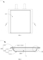
- the electrochemical device 1 includes a receiving housing 100 and an electrode assembly 200.
- the receiving housing 100 includes a first housing 110 and a second housing 120, which are arranged opposite to each other in a thickness direction Z of the electrochemical device 1 and together define a receiving cavity 101.
- the electrode assembly 200 is received in the receiving cavity 101.
- the first housing 110 includes a first polymer layer 114, a first metal layer 113 and a second polymer layer 115 disposed in a stacking manner.
- the first polymer layer 114 is disposed on a side of the first metal layer 113 facing the second housing 120, and the second polymer layer 115 is disposed on a side of the first metal layer 113 facing away from the second housing 120.
- the first polymer layer 114 is provided with a first through slot 1101 penetrating in the thickness direction, so that a surface of the first metal layer 113 includes a first area 1131 corresponding to the first through slot 1101 and a second area 1132 provided with the first polymer layer 114.
- the electrode assembly 200 is received in the receiving cavity 101.
- the first area 1131 is located between the electrode assembly 200 and the second polymer layer 115.
- the electrochemical device 1 is a soft-pack lithium ion battery.
- the electrochemical device 1 may be other electrochemical devices such as a sodium ion battery, which is not specifically limited in the present application.
- the receiving housing 100 includes a first housing 110 and a second housing 120.
- the first housing 110 and the second housing 120 are arranged opposite to each other in a thickness direction Z of the illustrated electrochemical device 1, and together define a receiving cavity 101 for receiving the electrode assembly 200.
- the first housing 110 includes a first cavity part 111 and a first flange part 112.
- the first cavity part 111 is of a box-like structure without a top, and includes a first base portion 1111 and a first side portion 1112.
- the first base portion 1111 is of a substantially flat sheet-like structure, and the first side portion 1112 extends from an edge of the first base portion 1111.
- the first base portion 1111 and the first side portion 1112 together define a first concave cavity 1011, and the first concave cavity 1011 is disposed facing the second housing 120.
- the first flange part 112 extends outward from one end of the first side portion 1112 facing away from the first base portion 1111 and is disposed integrally around the first cavity part 111.
- the second housing 120 is of a sheet-like structure and is provided at the first flange part 112 and closes the first concave cavity 1011.
- the receiving cavity 101 includes the first concave cavity 1011, and the receiving cavity 101 may further include other chambers depending on the actual shape of the receiving housing 100.
- the receiving cavity 101 further includes a concave cavity defined by the second housing 120.
- the first housing 110 is hot-melt fixed to the second housing 120 through the first flange part 112, and meanwhile achieves a seal. It will be appreciated that in other embodiments of the present application, the first housing 110 and the second housing 120 may also be fixed by other optional means such as adhesion.
- the first housing 110 includes a first metal layer 113, a first polymer layer 114, and a second polymer layer 115, and the first metal layer 113, the first polymer layer 114, and the second polymer layer 115 are stacked in the thickness direction Z.
- the first metal layer 113 is a substrate for bearing the first polymer layer 114 and the second polymer layer 115, and by virtue of the atom density distribution characteristic, the first metal layer may prevent gas-liquid exchange between the receiving cavity 101 and the electrochemical device 1, that is, prevent water vapor from entering the receiving cavity 101 from the outside and prevent electrolyte in the receiving cavity 101 from leaking from the inside to the outside.
- the first metal layer 113 has good thermal conductivity so that heat may be rapidly transferred outward when the temperature in the receiving cavity 101 is high.
- the first metal layer 113 is aluminum foil.
- the first metal layer 113 may also be other metal foil such as copper foil.
- the first polymer layer 114 is disposed on a side of the first metal layer 113 facing the second housing 120, and is provided with a first through slot 1101 penetrating in the thickness direction Z.
- the first metal layer 113 includes a first area 1131 disposed corresponding to the first through slot 1101 and a second area 1132 located outside the first area 1131.
- the first area 1131 is an area where the first polymer layer 114 is not provided
- the second area 1132 is an area where the first polymer layer 114 is provided.
- the material of the first polymer layer 114 includes at least one of: polypropylene, polycarbonate, polyamide, polyethylene, acrylonitrile-butadiene-styrene copolymer, polyoxymethylene, polyphenylene ether.
- the second polymer layer 115 is disposed on a side of the first metal layer 113 facing away from the second housing 120 and is an outer protective material layer of the first housing 110.
- the material of the second polymer layer 115 includes at least one of: polypropylene, polycarbonate, polyamide, polyethylene, acrylonitrile-butadiene-styrene copolymer, polyoxymethylene, polyphenylene ether.
- the second polymer layer 115 may or may not be of the same material as the first polymer layer 114.
- the second housing 120 includes a second metal layer 123, a third polymer layer 124, and a fourth polymer layer 125, and the second metal layer 123, the third polymer layer 124, and the fourth polymer layer 125 are stacked in the thickness direction Z.
- the second metal layer 123 is a substrate for bearing the third polymer layer 124 and the fourth polymer layer 125, and by virtue of the atom density distribution characteristic, the second metal layer may prevent gas-liquid exchange between the receiving cavity 101 and the electrochemical device 1, that is, prevent water vapor from entering the receiving cavity 101 from the outside and prevent the electrolyte in the receiving cavity 101 from leaking from the inside to the outside.
- the second metal layer 123 has good thermal conductivity so that heat may be rapidly transferred outward when the temperature in the receiving cavity 101 is high.
- the second metal layer 123 is aluminum foil.
- the second metal layer 123 may also be other metal foil such as copper foil.
- the third polymer layer 124 is disposed on a side of the second metal layer 123 facing the first housing 110, and the third polymer layer is hot-melt fixed to a portion of the first polymer layer 114 located at the first flange part 112. The selection of the material of the third polymer layer 124 may refer to the first polymer layer 114 and will not be described here.
- the third polymer layer 124 and the first polymer layer 114 are of the same material to facilitate better fusion of the two during hot-melt fixation.
- the fourth polymer layer 125 is disposed on a side of the second metal layer 123 facing away from the second housing 120 and is an outer protective material layer of the second housing 120. The selection of the material of the fourth polymer layer 125 may refer to the second polymer layer 115 and will not be described here.
- the fourth polymer layer 125 may or may not be of the same material as the third polymer layer 124.
- first housing 110 and the second housing 120 may be separately molded or may be integrally molded.
- first metal layer 113 and the second metal layer 123 are integrally molded
- first polymer layer 114 and the third polymer layer 124 are integrally molded
- second polymer layer 115 and the fourth polymer layer 125 are integrally molded.
- the electrode assembly 200 is received in the receiving cavity 101 and is a core element for realizing charging and discharging in the electrochemical device 1.
- the electrode assembly 200 includes a first electrode plate, a second electrode plate, and a separator disposed in a stacking manner. Polarities of the first electrode plate and the second electrode plate are opposite, and one of the first electrode plate and the second electrode plate is a positive electrode plate, and the other one is a negative electrode plate.
- the separator is arranged between the first electrode plate and the second electrode plate for separation.
- the electrode assembly 200 is of a winding structure.
- the electrode assembly 200 is wound into a cylindrical structure with an oblong cross section, and a thickness direction thereof coincides with the thickness direction Z, so that the electrode assembly is conveniently received in the receiving cavity 101. It will be understood that in other embodiments of the present application, the electrode assembly 200 may also be a laminated structure. Specifically, the first electrode plates and the second electrode plates are alternately arranged in the thickness direction, and the first electrode plate and the second electrode plate adjacent to the first electrode plate are separated by the separator.
- the first area 1131 is located between the electrode assembly 200 and the second polymer layer 115.
- the electrode assembly 200 is disposed in the first area 1131 (i.e., in the Z direction, a projection of the electrode assembly 200 on the first metal layer 113 falls within the first area 1131), and is in direct contact with the first area 1131.
- the first area 1131 may be provided to be large so that the projection of the electrode assembly 200 in the thickness direction Z lies entirely within the first area 1131.
- the first area 1131 may also be provided to be small so that a side of the electrode assembly 200 facing the first area 1131 is only partially in contact with the first area 1131.
- the first area 1131 is located at the first cavity part 111, and accordingly the second area 1132 is located at the first flange part 112.
- the first area 1131 is in a box shape as a whole and includes both a portion located at the first base portion 1111 and a portion located at the first side portion 1112.
- the first area 1131 may also be located at the first base portion 1111, and accordingly, the second area 1132 is located at the first side portion 1112 and the first flange part 112.
- the heat generated in the operation process of the electrode assembly 200 may be partially transferred directly to the first area 1131 of the first metal layer 113 through the first through slot 1101, and then transferred outward through the second polymer layer 115, rather than first passing through the first polymer layer 114, and then passing through the first metal layer 113 and the second polymer layer 115 in turn to be transferred outward. Therefore, with the arrangement of the first through slot 1101, dissipation of the internal heat of the electrochemical device 1 may be accelerated to a certain extent, thereby reducing the risk of thermal runaway of the electrochemical device 1.
- the present application is not limited thereto as long as it is guaranteed that: the first polymer layer 114 is provided with the first through slot 1101 to expose the first area 1131, and the first area 1131 is located between the electrode assembly 200 and the second polymer layer 115.
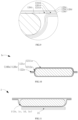
- FIG. 4 shows a cross-sectional (a cross-sectional direction may refer to the cross-sectional direction in FIG. 2 ) schematic view of an electrochemical device 1b according to another embodiment of the present application
- FIG. 5 shows a partially enlarged schematic view of a part C.
- the electrochemical device 1b still includes a receiving housing 100b and an electrode assembly 200b, and the receiving housing 100b includes a first housing 110b and a second housing 120b.
- the electrochemical device 1b is mainly different from the electrochemical device 1 described above in that: in the electrochemical device 1, the first housing 110 includes the first metal layer 113, the first polymer layer 114, and the second polymer layer 115, and the electrode assembly 200 is directly fixed to the first area 1131 of the first metal layer 113; while in the electrochemical device 1b, the first housing 110b includes a first thermal conductive material layer 116b in addition to a first metal layer 113b, a first polymer layer 114b and a second polymer layer 115b, and the electrode assembly 200b is fixed to a first area 1131b of the first metal layer 113b through the first thermal conductive material layer 116b.
- the first thermal conductive material layer 116b is disposed on a side of the first area 1131b facing a first through slot, and satisfies: 1.1 ⁇ ⁇ 3 / ⁇ 1 ⁇ 2.5, where ⁇ 1 denotes the thermal conductivity of the first metal layer 113b, and ⁇ 3 denotes the thermal conductivity of the first thermal conductive material layer 116b.
- ⁇ 1 denotes the thermal conductivity of the first metal layer 113b
- ⁇ 3 denotes the thermal conductivity of the first thermal conductive material layer 116b.
- the first metal layer is aluminum foil
- the first thermal conductive material layer 116b may be copper foil.
- the electrode assembly 200b is disposed opposite to the first thermal conductive material layer 116b. In this embodiment, the electrode assembly 200b is fixed to the first thermal conductive material layer 116b.
- the electrode assembly 200b may also be fixed to the first polymer layer 114b or the second housing 120b. Since the thermal conductivity of the first thermal conductive material layer 116b is greater than that of the first metal layer 113b, dissipation of internal heat of the electrochemical device 1b may be accelerated with arrangement of the thermal conductivity of the first thermal conductive material layer. In some embodiments, 1.5 ⁇ 3 / ⁇ 1 ⁇ 2, so that the bonding effect between the first thermal conductive material layer 116b and the first metal layer 113b may be improved, which is more conducive to the outward conduction of internal heat of the electrochemical device 1b.
- FIG. 6 shows a cross-sectional (a cross-sectional direction may refer to the cross-sectional direction in FIG. 2 ) schematic view of an electrochemical device 1c according to yet another embodiment of the present application
- FIG. 7 shows a partially enlarged schematic view of a part D
- the electrochemical device 1c still includes a receiving housing 100c and an electrode assembly 200c
- the receiving housing 100c includes a first housing 110c and a second housing 120c.
- the electrochemical device 1c is mainly different from the electrochemical device 1 described above in that: in the electrochemical device 1, only the first polymer layer 114 of the first housing 110 is provided with the first through slot 1101 to expose a portion of the first metal layer 113, i.e., the first area 1131; while in the electrochemical device 1c, the first housing 110c is provided in the same manner, and a third polymer layer 124c in the second housing 120c is provided with a second through slot 1201c penetrating in the thickness direction Z so as to expose a portion of a second metal layer 123c.
- the second metal layer 123c includes a third area 1231c disposed corresponding to the second through slot 1201c, and a fourth area 1232c located outside the third area 1231c, and the fourth area 1232c is an area provided with the third polymer layer 124c.
- the third area 1231c is located between the electrode assembly 200 and the fourth polymer layer 125c.
- a projection of the electrode assembly 200c on the second metal layer 123c falls within the third area 1231c in the thickness direction Z.
- the heat generated in the operation process of the electrode assembly 200c may be directly transferred to the third area 1231c of the second metal layer 123c through the second through slot 1201c, and then transferred outward through the fourth polymer layer 125c, rather than first passing through the third polymer layer 124c, and then passing through the second metal layer 123c and the fourth polymer layer 125c in turn to be transferred outward.
- the second through slot 1201c With the arrangement of the second through slot 1201c, dissipation of the internal heat of the electrochemical device 1 may be further accelerated, thereby reducing the risk of thermal runaway of the electrochemical device.
- FIG. 8 shows a cross-sectional (a cross-sectional direction may refer to the cross-sectional direction in FIG. 2 ) schematic view of an electrochemical device 1d according to yet another embodiment of the present application
- FIG. 9 shows a partially enlarged schematic view of a part E.
- the electrochemical device 1d still includes a receiving housing 100d and an electrode assembly 200d, and the receiving housing 100d includes a first housing 110d and a second housing 120d.
- the electrochemical device 1d is mainly different from the electrochemical device 1c described above in that: in the electrochemical device 1c, the second housing 120c includes the second metal layer 123c, the third polymer layer 124c and the fourth polymer layer 125c, and the electrode assembly 200c is directly fixed to the first area 1131 of the first metal layer 113 and the third area 1231 of the second metal layer 123c; while in the electrochemical device 1d, the second housing 120d includes a second thermal conductive material layer 126d in addition to a second metal layer 123d, a third polymer layer 124d and a fourth polymer layer 125d, and the electrode assembly 200d is fixed to a third area of the second metal layer 123d through the second thermal conductive material layer 126d.
- the second thermal conductive material layer 126 is disposed on a side of the third area 1231d facing a second through slot 1201d, and satisfies: 1.1 ⁇ ⁇ 4 / ⁇ 2 ⁇ 2.5, where ⁇ 2 denotes the thermal conductivity of the second metal layer 123d, and ⁇ 4 denotes the thermal conductivity of the second thermal conductive material layer 126d.
- the second metal layer is aluminum foil
- the second thermal conductive material layer 126d may be copper foil.
- the electrode assembly 200d is disposed opposite to the second thermal conductive material layer 126d. In this embodiment, the electrode assembly 200d is fixed to the second thermal conductive material layer 126d.
- the electrode assembly 200d may be fixed to the first polymer layer described above. Since the thermal conductivity of the second thermal conductive material layer 126d is greater than that of the second metal layer 121d, dissipation of internal heat of the electrochemical device may be accelerated with the arrangement of the second thermal conductive material layer. In some embodiments, 1.5 ⁇ 4 / ⁇ 2 ⁇ 2, so that the bonding effect between the second thermal conductive material layer 126d and the second metal layer 121d may be better, which is more conducive to the outward conduction of internal heat of the electrochemical device 1b.
- the second housing in each of the above embodiments is flat, in fact, the second housing may be in a shape similar to that of the first housing.
- the first housing in each embodiment is box-shaped, the first housing may also be of a flat structure, and the specific shapes of the first housing and the second housing are not limited herein.
- FIG. 10 which shows a cross-sectional schematic view of an electrochemical device 1e according to an embodiment of the present application, the electrochemical device is mainly different from the electrochemical devices provided by the above embodiments in that: a second housing 120e of the electrochemical device 1e is not flat but is of a substantially box-shaped structure and includes a second cavity part 121e and a second flange part 122e.
- the second cavity part 121e is of a box-like structure without a top and includes a second base portion 1211e and a second side portion 1212e.
- the second base portion 1211e is of a substantially flat sheet-like structure, and the second side portion 1212e extends from an edge of the second base portion 1211e.
- the second base portion 1211e and the second side portion 1212e together define a second concave cavity, the second concave cavity is arranged facing the first housing 110e, and the receiving cavity includes the second concave cavity.
- the second flange part 122e extends outward from one end of the second side portion 1212e facing away from the second base portion 1211e and is disposed integrally around the second cavity part 121e.
- the second flange part 122e is stacked and fixed to the first flange part so that the second housing 120e and the first housing together define the receiving cavity.
- the third area may be located in the second cavity part 121, and accordingly, the fourth area is located in the second flange part.
- the third area is located at the second base portion, and accordingly, the fourth area is located at the second side portion and the second flange part.
- the electrochemical device 1 provided in the present application includes the receiving housing 100 and the electrode assembly 200.
- the receiving housing 100 includes the first housing 110 and the second housing 120.
- the first housing 110 includes the first polymer layer 114, the first metal layer 113 and the second polymer layer 115 disposed in a stacking manner.
- the first polymer layer 114 is disposed on the side of the first metal layer 113 facing the second housing 120.
- the first polymer layer 114 is provided with the first through slot 1101, so that the first metal layer 113 includes the first area 1131 provided corresponding to the first through slot 1101 and the second area 1132 provided with the first polymer layer 114.
- the first area 1131 is located between the electrode assembly 200 and the second polymer layer 115.
- the electrochemical device With the arrangement of the first through slot 1101, heat generated in the operation process of the electrode assembly may not be blocked by the first polymer layer 114 when transferred to the first through slot 1101, but may be transferred outward through the first metal layer 113 with a high thermal conductivity. Therefore, the electrochemical device provided by some embodiments of the present application can improve the current situation of continuous accumulation of internal heat in the operation process of the electrochemical device, thereby reducing the risk of thermal runaway of the electrochemical device.
- the present application further provides an electrochemical device component 2.
- the electrochemical device component 2 includes a wireless charging module 21 and the electrochemical devices 1 (1b, 1c, 1d, and 1e) in the above-described embodiments.
- the wireless charging module 21 includes a charging coil, and the wireless charging module 21 is arranged on the outer surface of the second polymer layer 115.
- the wireless charging module 21 is electrically connected to the electrochemical device 1 and is used for charging the electrochemical device 1.
- the wireless charging module 21 is disposed opposite to the first area.
- the electrochemical device component 2 is a wireless rechargeable battery.
- the electrochemical device component 2 may also be a module or other device in a wireless rechargeable battery.
- the electrochemical device component includes the electrochemical device in the above embodiments, the electrochemical device component 2 can improve the current situation of continuous accumulation of internal heat in the operation process of the electrochemical device, thereby reducing the risk of thermal runaway of the electrochemical device.
- the wireless rechargeable battery on the market at present needs to be additionally provided with a graphite material layer with high thermal conductivity in the wireless charging module due to the poor heat dissipation performance of electrochemical devices, which leads to the large overall size of the wireless rechargeable battery.
- the electrochemical device in the electrochemical device component 2 provided by some embodiments of the present application has better heat dissipation performance, so that the graphite material layer in the wireless charging module can be omitted, and further the current situation that the current wireless rechargeable battery occupies a large size can be improved.
- the present application further provides an electronic device 3.
- the electronic device includes the electrochemical device component 2 in the above embodiment and a load structure powered by the electrochemical device component 2.
- the electronic device 3 includes a mobile phone. It will be appreciated that in other embodiments of the present application, the electronic device may also be a tablet computer, a computer, a drone or other electrically powered device.
- the electronic device 3 may further include only the electrochemical device described in any one of the above embodiments.
- the electronic device 3 can improve the current situation of continuous accumulation of internal heat in the operation process of the electrochemical device, thereby reducing the risk of thermal runaway of the electrochemical device.
Landscapes
- Chemical & Material Sciences (AREA)
- Chemical Kinetics & Catalysis (AREA)
- Electrochemistry (AREA)
- General Chemical & Material Sciences (AREA)
- Engineering & Computer Science (AREA)
- Manufacturing & Machinery (AREA)
- Inorganic Chemistry (AREA)
- Materials Engineering (AREA)
- Sealing Battery Cases Or Jackets (AREA)
Abstract
The present application relates to the technical field of energy storage, and discloses an electrochemical device (1), an electrochemical device component (2), and an electronic device (3). The electrochemical device (1) includes a receiving housing (100) and an electrode assembly (200). The receiving housing (100) includes a first housing (110) and a second housing (120), the first housing (110) and the second housing (120) are arranged opposite to each other in a thickness direction of the electrochemical device (1), and together define a receiving cavity (101). The first housing (110) includes a first polymer layer (114), a first metal layer (113) and a second polymer layer (115) disposed in a stacking manner, the first polymer layer (114) is arranged on a side of the first metal layer (113) facing the second housing (120), and the first polymer layer (114) is provided with a first through slot (1101) penetrating in the thickness direction, so that a surface of the first metal layer (113) includes a first area (1131) corresponding to the first through slot (1101) and a second area provided with the first polymer layer (114), and the first area is located between the electrode assembly (200) and the second polymer layer (115). The electrochemical device (1) can improve the current situation of continuous accumulation of internal heat in the operation process of the electrochemical device (1), thereby reducing the risk of thermal runaway of the electrochemical device (1).
Description
- The present application relates to the technical field of energy storage, in particular to an electrochemical device, an electrochemical device component, and an electronic device.
- An electrochemical device is a device that converts external energy into electric energy and stores the electric energy therein, so as to supply power to external devices (such as portable electronic devices) at the time of need. Generally, an electrochemical device includes a receiving housing, an electrode assembly received in the receiving housing, and battery tabs. The receiving housing defines a receiving cavity for receiving the electrode assembly. The electrode assembly includes a first electrode plate, a second electrode plate, and a separator. A polarity of the first electrode plate is opposite to that of the second electrode plate, and the separator is arranged between the first electrode plate and the second electrode plate for separation. One end of one of the battery tabs is connected to the first electrode plate, and the other end of the battery tab extends out of the receiving housing; and one end of the other battery tab is connected to the second electrode plate, and the other end of the battery tab extends out of the receiving housing.
- Presently, the receiving housing of the electrochemical device generally includes a first polymer layer, a metal layer, and a second polymer layer disposed in a stacking manner. The first polymer layer is arranged on one side of the metal layer facing the inside of the receiving housing, and due to the arrangement of the first polymer layer, hot melt packaging of the receiving housing is facilitated. The second polymer layer is arranged on the side of the metal layer facing the outside of the receiving housing, so as to reduce the corrosion rate of the metal layer by the external environment.
- The applicant(s) of the present application has discovered in the process of implementing the present application that: in the operation process of an electrochemical device, an electrode assembly may generate a large amount of heat, and the heat may accumulate continuously in a receiving housing, which may cause thermal runaway of the electrochemical device.
- The present application aims to provide an electrochemical device, an electrochemical device component, and an electronic device to reduce the risk of thermal runaway in current electrochemical devices.
- In order to solve the above technical problems, the present application adopts the following technical solutions:
In a first aspect, some embodiments of the present application provide an electrochemical device. The electrochemical device includes a receiving housing and an electrode assembly. The receiving housing includes a first housing and a second housing, the first housing and the second housing are arranged opposite to each other in a thickness direction of the electrochemical device, and together define a receiving cavity. The electrode assembly is received in the receiving cavity. The first housing includes a first polymer layer, a first metal layer and a second polymer layer disposed in a stacking manner, the first polymer layer is arranged on a side of the first metal layer facing the second housing, the second polymer layer is arranged on a side of the first metal layer facing away from the second housing, and the first polymer layer is provided with a first through slot penetrating in the thickness direction, so that a surface of the first metal layer facing the second housing includes a first area corresponding to the first through slot and a second area provided with the first polymer layer, and the first area is located between the electrode assembly and the second polymer layer. - In the electrochemical device provided by some embodiments of the present application, the first polymer layer is provided with the first through slot, so that heat generated by the electrode assembly in the operation process may not be blocked by the first polymer layer when transferred to the first through slot, but may be transferred outward through the first metal layer with a high thermal conductivity. Therefore, the electrochemical device provided by some embodiments of the present application can improve the current situation of continuous accumulation of internal heat in the operation process of the electrochemical device, thereby reducing the risk of thermal runaway of the electrochemical device.
- In some embodiments, a projection of the electrode assembly on the first metal layer falls within the first area in the thickness direction of the electrochemical device. With this arrangement, the electrode assembly may be in direct contact with the first area, so that heat generated by the electrode assembly in the operation process may not be blocked by the first polymer layer when transferred to the first through slot, but may be transferred outward through the first metal layer with a high thermal conductivity.
- In some embodiments, the first housing further includes a first thermal conductive material layer. The first thermal conductive material layer is arranged on a side of the first area facing the first through slot, a thermal conductivity of the first metal layer is λ1, a thermal conductivity of the first thermal conductive material layer is λ3, and 1.1 ≤ λ3/λ1 ≤ 2.5; and the electrode assembly is opposite to the first thermal conductive material layer. Since the thermal conductivity of the first thermal conductive material layer is greater than that of the first metal layer, dissipation of internal heat of the electrochemical device may be accelerated with this arrangement. In some embodiments, 1.5≤λ3/λ1≤2, so that the bonding effect between the first thermal conductive material layer and the first metal layer may be improved, which is more conducive to the outward conduction of internal heat of the electrochemical device.
- In some embodiments, the first housing includes a first cavity part and a first flange part. The first cavity part includes a first base portion and a first side portion extending from an edge of the first base portion, the first base portion and the first side portion together define a first concave cavity, and the receiving cavity includes the first concave cavity. The first flange part extends outward from one end of the first side portion facing away from the first base portion. The first area is located at the first cavity part, the second area is located at the first flange part, or the first area is located at the first base portion, and the second area is located at the first side portion and the first flange part.
- In some embodiments, the second housing includes a third polymer layer, a second metal layer and a fourth polymer layer disposed in a stacking manner, the third polymer layer is disposed on a side of the second metal layer facing the first housing, and the fourth polymer layer is disposed on a side of the second metal layer facing away from the first housing. The third polymer layer is provided with a second through slot penetrating in the thickness direction, a surface of the second metal layer includes a third area corresponding to the second through slot and a fourth area provided with the third polymer layer, and the third area is located between the electrode assembly and the fourth polymer layer.
- In this way, the heat generated by the electrode assembly in the operation process can be directly transferred to the third area of the second metal layer through the second through slot, and then transferred outward through the fourth polymer layer, rather than first passing through the third polymer layer, and then passing through the second metal layer and the fourth polymer layer in turn to be transferred outward. With the arrangement of the second through slot, the dissipation of internal heat in the electrochemical device may be further accelerated, thereby reducing the risk of thermal runaway of the electrochemical device.
- In some embodiments, a projection of the electrode assembly on the second metal layer falls within the third area in the thickness direction of the electrochemical device. With this arrangement, the electrode assembly may be in direct contact with the third area, so that heat generated by the electrode assembly in the operation process may not be blocked by the third polymer layer when transferred to the second through slot, but may be transferred outward through the second metal layer with a high thermal conductivity.
- In some embodiments, the second housing further includes a second thermal conductive material layer. The second thermal conductive material layer is arranged on a side of the third area facing the second through slot, a thermal conductivity of the second metal layer is λ2, a thermal conductivity of the second thermal conductive material layer is λ4, and 1.1 ≤ λ4/λ2 ≤ 2.5; and the electrode assembly is opposite to the second thermal conductive material layer. Since the thermal conductivity of the second thermal conductive material layer is greater than that of the second metal layer, dissipation of internal heat of the electrochemical device may be accelerated with the arrangement of the second thermal conductive material layer. In some embodiments, 1.5≤λ4/λ2≤2, so that the bonding effect between the second thermal conductive material layer and the second metal layer may be improved, which is more conducive to the outward conduction of internal heat of the electrochemical device.
- In some embodiments, the second housing includes a second cavity part and a second flange part. The second cavity part includes a second base portion and a second side portion extending from an edge of the second base portion, the second base portion and the second side portion together define a second concave cavity, and the receiving cavity includes the second concave cavity. The second flange part extends outward from one end of the second side portion facing away from the second base portion; and the third area is located at the second cavity part, the fourth area is located at the second flange part, or the third area is located at the second base portion, and the fourth area is located at the second side portion and the second flange part.
- In some embodiments, the first polymer layer is integrally formed with the third polymer layer, the first metal layer is integrally formed with the second metal layer, and the second polymer layer is integrally formed with the fourth polymer layer. By adopting this solution, the packaging process may be simplified.
- In a second aspect, some embodiments of the present application further provide an electrochemical device component. The electrochemical device component includes a wireless charging module and the electrochemical device described above. The wireless charging module includes a charging coil arranged on an outer surface of the second polymer layer. Since the electrochemical device component includes the electrochemical device in the above embodiments, the electrochemical device component can improve the current situation of continuous accumulation of internal heat in the operation process of the electrochemical device, thereby reducing the risk of thermal runaway of the electrochemical device.
- In a third aspect, some embodiments of the present application further provide an electronic device. The electronic device includes the electrochemical device or electrochemical device component described above. Since the electronic device includes the electrochemical device or the electrochemical device component described above, the electronic device provided by some embodiments of the present application may improve the current situation of continuous accumulation of internal heat in the operation process of the electrochemical device to some extent, thereby reducing the risk of thermal runaway of the electrochemical device.
- In order to more clearly illustrate the technical solutions in embodiments of the present application, the following will briefly introduce the drawings that are desired to be used in the description of the provided embodiments. Apparently, the drawings in the following description are merely some embodiments of the present application, from which other drawings can be obtained by those ordinarily skilled in the art according to the structures shown in these drawings.
-
FIG. 1 is a schematic diagram of an electrochemical device according to an embodiment of the present application; -
FIG. 2 is a cross-sectional schematic view of the electrochemical device inFIG. 1 taken in a line A-A; -
FIG. 3 is a partially enlarged schematic view of a part B inFIG. 2 ; -
FIG. 4 is a cross-sectional schematic view of an electrochemical device according to another embodiment of the present application; -
FIG. 5 is a partially enlarged schematic view of a part C inFIG. 4 ; -
FIG. 6 is a cross-sectional schematic view of an electrochemical device according to yet another embodiment of the present application; -
FIG. 7 is a partially enlarged schematic view of a part D inFIG. 6 ; -
FIG. 8 is a cross-sectional schematic view of an electrochemical device according to yet another embodiment of the present application; -
FIG. 9 is a partially enlarged schematic view of a part E inFIG. 8 ; -
FIG. 10 is a cross-sectional schematic view of an electrochemical device according to an embodiment of the present application; -
FIG. 11 is a cross-sectional schematic view of an electrochemical device component according to an embodiment of the present application; and -
FIG. 12 is a schematic diagram of an electronic device according to an embodiment of the present application. - In the drawings:
- 1, Electrochemical device;
- 100. Receiving housing; 110. First housing; 120. Second housing; 111. First cavity part; 112. First flange part; 113. First metal layer; 114. First polymer layer; 115. Second polymer layer; 123. Second metal layer; 124. Third polymer layer; 125. Fourth polymer layer; 1111. First base portion; 1112. First side portion; 1131. First area; 1132. Second area; 101. Receiving cavity; 1011. First concave cavity; 1101. First through slot;
- 200. Electrode assembly;
- 100b. Receiving housing; 110b. First housing; 120b. Second housing; 113b. First metal layer; 114b. First polymer layer; 115b. Second polymer layer; 1131b. First area; 1132b. Second area; 116b. First thermal conductive material layer;
- 200b. Electrode assembly;
- 100c. Receiving housing; 110c. First housing; 120c. Second housing; 123c. Second metal layer; 124c. Third polymer layer; 125c. Fourth polymer layer; 126d. Second thermal conductive material layer; 1131c. First area; 1231c. Third area; 1232. Fourth area; 1201c. Second through slot;
- 200d. Electrode assembly;
- 100e. Receiving housing; 120e. Second housing; 121e. Second cavity part; 122e. Second flange part; 1211e. Second base portion; 1212e. Second side portion;
- 2. Electrochemical device component; 21. Wireless charging module; and
- 3. Electronic device.
- For ease of understanding the present application, a more detailed description of the present application is given below in conjunction with the accompanying drawings and specific embodiments. It should be noted that when an element is expressed as "fixed to"/"secured to" another element, it may be directly on the other element, or there may be one or more intervening elements there between. When an element is described as "connected" to another element, it may be directly connected to the other element, or there may be one or more intervening elements there between. The terms "vertical", "horizontal", "left", "right", "inside", "outside" and similar expressions used in the description are for illustrative purposes only.
- Unless otherwise defined, all technical and scientific terms used herein have the same meanings as commonly understood by those skilled in the art of the present application. Terms used in the description of the present application are for the purpose of describing specific embodiments only and are not intended to limit the present application. The term "and/or" as used herein includes any and all combinations of one or more related listed items.
- Further, the technical features described below in different embodiments of the present application may be combined with each other as long as they do not conflict with each other.
- In the description, "mounting" includes fixing or limiting a certain element or device to a specific position or place by welding, screwing, clamping, bonding, etc. The element or device may remain immovable or move within a limited range in a specific position or place, and may or may not be removed after being fixed or limited to a specific position or place, which is not limited in the provided embodiments of the present application.
- Referring to
FIG. 1 to FIG. 3 , which respectively show a schematic diagram of anelectrochemical device 1 provided by an embodiment of the present application, a sectional schematic diagram of theelectrochemical device 1 taken in line A-A, and a partially enlarged schematic diagram of a part B, theelectrochemical device 1 includes a receivinghousing 100 and anelectrode assembly 200. The receivinghousing 100 includes afirst housing 110 and asecond housing 120, which are arranged opposite to each other in a thickness direction Z of theelectrochemical device 1 and together define a receivingcavity 101. Theelectrode assembly 200 is received in the receivingcavity 101. Thefirst housing 110 includes afirst polymer layer 114, afirst metal layer 113 and asecond polymer layer 115 disposed in a stacking manner. Thefirst polymer layer 114 is disposed on a side of thefirst metal layer 113 facing thesecond housing 120, and thesecond polymer layer 115 is disposed on a side of thefirst metal layer 113 facing away from thesecond housing 120. Thefirst polymer layer 114 is provided with a first throughslot 1101 penetrating in the thickness direction, so that a surface of thefirst metal layer 113 includes afirst area 1131 corresponding to the first throughslot 1101 and asecond area 1132 provided with thefirst polymer layer 114. Theelectrode assembly 200 is received in the receivingcavity 101. Thefirst area 1131 is located between theelectrode assembly 200 and thesecond polymer layer 115. Next, the specific structure of theelectrochemical device 1 is described in the case where theelectrochemical device 1 is a soft-pack lithium ion battery. However, it should be understood that in other embodiments of the present application, theelectrochemical device 1 may be other electrochemical devices such as a sodium ion battery, which is not specifically limited in the present application. - For the receiving
housing 100, referring toFIG. 1 and FIG. 2 firstly, the receivinghousing 100 includes afirst housing 110 and asecond housing 120. Thefirst housing 110 and thesecond housing 120 are arranged opposite to each other in a thickness direction Z of the illustratedelectrochemical device 1, and together define a receivingcavity 101 for receiving theelectrode assembly 200. - Referring further to
FIG. 1 to FIG. 3 , thefirst housing 110 includes afirst cavity part 111 and afirst flange part 112. Thefirst cavity part 111 is of a box-like structure without a top, and includes afirst base portion 1111 and afirst side portion 1112. Thefirst base portion 1111 is of a substantially flat sheet-like structure, and thefirst side portion 1112 extends from an edge of thefirst base portion 1111. Thefirst base portion 1111 and thefirst side portion 1112 together define a firstconcave cavity 1011, and the firstconcave cavity 1011 is disposed facing thesecond housing 120. Thefirst flange part 112 extends outward from one end of thefirst side portion 1112 facing away from thefirst base portion 1111 and is disposed integrally around thefirst cavity part 111. - Referring further to
FIG. 1 to FIG. 3 , thesecond housing 120 is of a sheet-like structure and is provided at thefirst flange part 112 and closes the firstconcave cavity 1011. Thus, thefirst housing 110 and thesecond housing 120 together define the receivingcavity 101. The receivingcavity 101 includes the firstconcave cavity 1011, and the receivingcavity 101 may further include other chambers depending on the actual shape of the receivinghousing 100. For example, when thesecond housing 120 partially expands facing away from thefirst housing 110, the receivingcavity 101 further includes a concave cavity defined by thesecond housing 120. In this embodiment, thefirst housing 110 is hot-melt fixed to thesecond housing 120 through thefirst flange part 112, and meanwhile achieves a seal. It will be appreciated that in other embodiments of the present application, thefirst housing 110 and thesecond housing 120 may also be fixed by other optional means such as adhesion. - Next, the configurations of the
first housing 110 and thesecond housing 120 will be described respectively. - Referring to
FIG. 3 , thefirst housing 110 includes afirst metal layer 113, afirst polymer layer 114, and asecond polymer layer 115, and thefirst metal layer 113, thefirst polymer layer 114, and thesecond polymer layer 115 are stacked in the thickness direction Z. Thefirst metal layer 113 is a substrate for bearing thefirst polymer layer 114 and thesecond polymer layer 115, and by virtue of the atom density distribution characteristic, the first metal layer may prevent gas-liquid exchange between the receivingcavity 101 and theelectrochemical device 1, that is, prevent water vapor from entering the receivingcavity 101 from the outside and prevent electrolyte in the receivingcavity 101 from leaking from the inside to the outside. In addition, thefirst metal layer 113 has good thermal conductivity so that heat may be rapidly transferred outward when the temperature in the receivingcavity 101 is high. Optionally, thefirst metal layer 113 is aluminum foil. Of course, in other embodiments of the present application, thefirst metal layer 113 may also be other metal foil such as copper foil. Thefirst polymer layer 114 is disposed on a side of thefirst metal layer 113 facing thesecond housing 120, and is provided with a first throughslot 1101 penetrating in the thickness direction Z. Thus, thefirst metal layer 113 includes afirst area 1131 disposed corresponding to the first throughslot 1101 and asecond area 1132 located outside thefirst area 1131. In other words, thefirst area 1131 is an area where thefirst polymer layer 114 is not provided, and thesecond area 1132 is an area where thefirst polymer layer 114 is provided. Optionally, the material of thefirst polymer layer 114 includes at least one of: polypropylene, polycarbonate, polyamide, polyethylene, acrylonitrile-butadiene-styrene copolymer, polyoxymethylene, polyphenylene ether. Thesecond polymer layer 115 is disposed on a side of thefirst metal layer 113 facing away from thesecond housing 120 and is an outer protective material layer of thefirst housing 110. Optionally, the material of thesecond polymer layer 115 includes at least one of: polypropylene, polycarbonate, polyamide, polyethylene, acrylonitrile-butadiene-styrene copolymer, polyoxymethylene, polyphenylene ether. Thesecond polymer layer 115 may or may not be of the same material as thefirst polymer layer 114. - Referring further to
FIG. 3 , thesecond housing 120 includes asecond metal layer 123, athird polymer layer 124, and afourth polymer layer 125, and thesecond metal layer 123, thethird polymer layer 124, and thefourth polymer layer 125 are stacked in the thickness direction Z. Thesecond metal layer 123 is a substrate for bearing thethird polymer layer 124 and thefourth polymer layer 125, and by virtue of the atom density distribution characteristic, the second metal layer may prevent gas-liquid exchange between the receivingcavity 101 and theelectrochemical device 1, that is, prevent water vapor from entering the receivingcavity 101 from the outside and prevent the electrolyte in the receivingcavity 101 from leaking from the inside to the outside. In addition, thesecond metal layer 123 has good thermal conductivity so that heat may be rapidly transferred outward when the temperature in the receivingcavity 101 is high. Optionally, thesecond metal layer 123 is aluminum foil. Of course, in other embodiments of the present application, thesecond metal layer 123 may also be other metal foil such as copper foil. Thethird polymer layer 124 is disposed on a side of thesecond metal layer 123 facing thefirst housing 110, and the third polymer layer is hot-melt fixed to a portion of thefirst polymer layer 114 located at thefirst flange part 112. The selection of the material of thethird polymer layer 124 may refer to thefirst polymer layer 114 and will not be described here. Optionally, thethird polymer layer 124 and thefirst polymer layer 114 are of the same material to facilitate better fusion of the two during hot-melt fixation. Thefourth polymer layer 125 is disposed on a side of thesecond metal layer 123 facing away from thesecond housing 120 and is an outer protective material layer of thesecond housing 120. The selection of the material of thefourth polymer layer 125 may refer to thesecond polymer layer 115 and will not be described here. Thefourth polymer layer 125 may or may not be of the same material as thethird polymer layer 124. - It is worth mentioning that the
first housing 110 and thesecond housing 120 may be separately molded or may be integrally molded. When the first housing and the second housing are integrally molded, thefirst metal layer 113 and thesecond metal layer 123 are integrally molded, thefirst polymer layer 114 and thethird polymer layer 124 are integrally molded, and thesecond polymer layer 115 and thefourth polymer layer 125 are integrally molded. - Referring to
FIG. 2 , for theelectrode assembly 200, theelectrode assembly 200 is received in the receivingcavity 101 and is a core element for realizing charging and discharging in theelectrochemical device 1. Theelectrode assembly 200 includes a first electrode plate, a second electrode plate, and a separator disposed in a stacking manner. Polarities of the first electrode plate and the second electrode plate are opposite, and one of the first electrode plate and the second electrode plate is a positive electrode plate, and the other one is a negative electrode plate. The separator is arranged between the first electrode plate and the second electrode plate for separation. In this embodiment, theelectrode assembly 200 is of a winding structure. Specifically, theelectrode assembly 200 is wound into a cylindrical structure with an oblong cross section, and a thickness direction thereof coincides with the thickness direction Z, so that the electrode assembly is conveniently received in the receivingcavity 101. It will be understood that in other embodiments of the present application, theelectrode assembly 200 may also be a laminated structure. Specifically, the first electrode plates and the second electrode plates are alternately arranged in the thickness direction, and the first electrode plate and the second electrode plate adjacent to the first electrode plate are separated by the separator. - In this embodiment, the
first area 1131 is located between theelectrode assembly 200 and thesecond polymer layer 115. In another embodiment, theelectrode assembly 200 is disposed in the first area 1131 (i.e., in the Z direction, a projection of theelectrode assembly 200 on thefirst metal layer 113 falls within the first area 1131), and is in direct contact with thefirst area 1131. Thefirst area 1131 may be provided to be large so that the projection of theelectrode assembly 200 in the thickness direction Z lies entirely within thefirst area 1131. Of course, thefirst area 1131 may also be provided to be small so that a side of theelectrode assembly 200 facing thefirst area 1131 is only partially in contact with thefirst area 1131. For example, in some embodiments, thefirst area 1131 is located at thefirst cavity part 111, and accordingly thesecond area 1132 is located at thefirst flange part 112. In this case, thefirst area 1131 is in a box shape as a whole and includes both a portion located at thefirst base portion 1111 and a portion located at thefirst side portion 1112. For another example, in other embodiments, thefirst area 1131 may also be located at thefirst base portion 1111, and accordingly, thesecond area 1132 is located at thefirst side portion 1112 and thefirst flange part 112. - The heat generated in the operation process of the
electrode assembly 200 may be partially transferred directly to thefirst area 1131 of thefirst metal layer 113 through the first throughslot 1101, and then transferred outward through thesecond polymer layer 115, rather than first passing through thefirst polymer layer 114, and then passing through thefirst metal layer 113 and thesecond polymer layer 115 in turn to be transferred outward. Therefore, with the arrangement of the first throughslot 1101, dissipation of the internal heat of theelectrochemical device 1 may be accelerated to a certain extent, thereby reducing the risk of thermal runaway of theelectrochemical device 1. - It should be understood that even though this embodiment is described with the
first housing 110 being of a box-shaped structure and theelectrode assembly 200 being in direct contact with thefirst area 1131 in thefirst housing 110, the present application is not limited thereto as long as it is guaranteed that: thefirst polymer layer 114 is provided with the first throughslot 1101 to expose thefirst area 1131, and thefirst area 1131 is located between theelectrode assembly 200 and thesecond polymer layer 115. - For example,
FIG. 4 shows a cross-sectional (a cross-sectional direction may refer to the cross-sectional direction inFIG. 2 ) schematic view of anelectrochemical device 1b according to another embodiment of the present application, andFIG. 5 shows a partially enlarged schematic view of a part C. Theelectrochemical device 1b still includes a receivinghousing 100b and anelectrode assembly 200b, and the receivinghousing 100b includes afirst housing 110b and asecond housing 120b. Theelectrochemical device 1b is mainly different from theelectrochemical device 1 described above in that: in theelectrochemical device 1, thefirst housing 110 includes thefirst metal layer 113, thefirst polymer layer 114, and thesecond polymer layer 115, and theelectrode assembly 200 is directly fixed to thefirst area 1131 of thefirst metal layer 113; while in theelectrochemical device 1b, thefirst housing 110b includes a first thermalconductive material layer 116b in addition to a first metal layer 113b, afirst polymer layer 114b and a second polymer layer 115b, and theelectrode assembly 200b is fixed to afirst area 1131b of the first metal layer 113b through the first thermalconductive material layer 116b. Specifically, the first thermalconductive material layer 116b is disposed on a side of thefirst area 1131b facing a first through slot, and satisfies: 1.1 ≤ λ3/λ1 ≤ 2.5, where λ1 denotes the thermal conductivity of the first metal layer 113b, and λ3 denotes the thermal conductivity of the first thermalconductive material layer 116b. For example, when the first metal layer is aluminum foil, the first thermalconductive material layer 116b may be copper foil. Theelectrode assembly 200b is disposed opposite to the first thermalconductive material layer 116b. In this embodiment, theelectrode assembly 200b is fixed to the first thermalconductive material layer 116b. Of course, in other embodiments, theelectrode assembly 200b may also be fixed to thefirst polymer layer 114b or thesecond housing 120b. Since the thermal conductivity of the first thermalconductive material layer 116b is greater than that of the first metal layer 113b, dissipation of internal heat of theelectrochemical device 1b may be accelerated with arrangement of the thermal conductivity of the first thermal conductive material layer. In some embodiments, 1.5≤λ3/λ1≤2, so that the bonding effect between the first thermalconductive material layer 116b and the first metal layer 113b may be improved, which is more conducive to the outward conduction of internal heat of theelectrochemical device 1b. - For example,
FIG. 6 shows a cross-sectional (a cross-sectional direction may refer to the cross-sectional direction inFIG. 2 ) schematic view of anelectrochemical device 1c according to yet another embodiment of the present application, andFIG. 7 shows a partially enlarged schematic view of a part D, theelectrochemical device 1c still includes a receivinghousing 100c and anelectrode assembly 200c, and the receivinghousing 100c includes afirst housing 110c and asecond housing 120c. Theelectrochemical device 1c is mainly different from theelectrochemical device 1 described above in that: in theelectrochemical device 1, only thefirst polymer layer 114 of thefirst housing 110 is provided with the first throughslot 1101 to expose a portion of thefirst metal layer 113, i.e., thefirst area 1131; while in theelectrochemical device 1c, thefirst housing 110c is provided in the same manner, and athird polymer layer 124c in thesecond housing 120c is provided with a second throughslot 1201c penetrating in the thickness direction Z so as to expose a portion of asecond metal layer 123c. Specifically, thesecond metal layer 123c includes athird area 1231c disposed corresponding to the second throughslot 1201c, and afourth area 1232c located outside thethird area 1231c, and thefourth area 1232c is an area provided with thethird polymer layer 124c. Thethird area 1231c is located between theelectrode assembly 200 and the fourth polymer layer 125c. In this embodiment, a projection of theelectrode assembly 200c on thesecond metal layer 123c falls within thethird area 1231c in the thickness direction Z. Thus, the heat generated in the operation process of theelectrode assembly 200c may be directly transferred to thethird area 1231c of thesecond metal layer 123c through the second throughslot 1201c, and then transferred outward through the fourth polymer layer 125c, rather than first passing through thethird polymer layer 124c, and then passing through thesecond metal layer 123c and the fourth polymer layer 125c in turn to be transferred outward. With the arrangement of the second throughslot 1201c, dissipation of the internal heat of theelectrochemical device 1 may be further accelerated, thereby reducing the risk of thermal runaway of the electrochemical device. - For example,
FIG. 8 shows a cross-sectional (a cross-sectional direction may refer to the cross-sectional direction inFIG. 2 ) schematic view of an electrochemical device 1d according to yet another embodiment of the present application, andFIG. 9 shows a partially enlarged schematic view of a part E. The electrochemical device 1d still includes a receivinghousing 100d and anelectrode assembly 200d, and the receivinghousing 100d includes afirst housing 110d and asecond housing 120d. The electrochemical device 1d is mainly different from theelectrochemical device 1c described above in that: in theelectrochemical device 1c, thesecond housing 120c includes thesecond metal layer 123c, thethird polymer layer 124c and the fourth polymer layer 125c, and theelectrode assembly 200c is directly fixed to thefirst area 1131 of thefirst metal layer 113 and the third area 1231 of thesecond metal layer 123c; while in the electrochemical device 1d, thesecond housing 120d includes a second thermalconductive material layer 126d in addition to asecond metal layer 123d, athird polymer layer 124d and afourth polymer layer 125d, and theelectrode assembly 200d is fixed to a third area of thesecond metal layer 123d through the second thermalconductive material layer 126d. Specifically, the second thermal conductive material layer 126 is disposed on a side of thethird area 1231d facing a second throughslot 1201d, and satisfies: 1.1 ≤ λ4/λ2 ≤ 2.5, where λ2 denotes the thermal conductivity of thesecond metal layer 123d, and λ4 denotes the thermal conductivity of the second thermalconductive material layer 126d. For example, when the second metal layer is aluminum foil, the second thermalconductive material layer 126d may be copper foil. Theelectrode assembly 200d is disposed opposite to the second thermalconductive material layer 126d. In this embodiment, theelectrode assembly 200d is fixed to the second thermalconductive material layer 126d. Of course, in other embodiments, theelectrode assembly 200d may be fixed to the first polymer layer described above. Since the thermal conductivity of the second thermalconductive material layer 126d is greater than that of the second metal layer 121d, dissipation of internal heat of the electrochemical device may be accelerated with the arrangement of the second thermal conductive material layer. In some embodiments, 1.5≤λ4/λ2≤2, so that the bonding effect between the second thermalconductive material layer 126d and the second metal layer 121d may be better, which is more conducive to the outward conduction of internal heat of theelectrochemical device 1b. - It is to be understood that the present application may also be adaptively combined or modified on the basis of the above embodiments, which will not be described herein.
- In addition, even though the second housing in each of the above embodiments is flat, in fact, the second housing may be in a shape similar to that of the first housing. Similarly, even though the first housing in each embodiment is box-shaped, the first housing may also be of a flat structure, and the specific shapes of the first housing and the second housing are not limited herein. For example, referring to
FIG. 10 , which shows a cross-sectional schematic view of an electrochemical device 1e according to an embodiment of the present application, the electrochemical device is mainly different from the electrochemical devices provided by the above embodiments in that: asecond housing 120e of the electrochemical device 1e is not flat but is of a substantially box-shaped structure and includes asecond cavity part 121e and asecond flange part 122e. Thesecond cavity part 121e is of a box-like structure without a top and includes asecond base portion 1211e and asecond side portion 1212e. Thesecond base portion 1211e is of a substantially flat sheet-like structure, and thesecond side portion 1212e extends from an edge of thesecond base portion 1211e. Thesecond base portion 1211e and thesecond side portion 1212e together define a second concave cavity, the second concave cavity is arranged facing the first housing 110e, and the receiving cavity includes the second concave cavity. Thesecond flange part 122e extends outward from one end of thesecond side portion 1212e facing away from thesecond base portion 1211e and is disposed integrally around thesecond cavity part 121e. Thesecond flange part 122e is stacked and fixed to the first flange part so that thesecond housing 120e and the first housing together define the receiving cavity. When thesecond housing 120e has the third area and the fourth area, the third area may be located in the second cavity part 121, and accordingly, the fourth area is located in the second flange part. Alternatively, the third area is located at the second base portion, and accordingly, the fourth area is located at the second side portion and the second flange part. - In summary, the
electrochemical device 1 provided in the present application includes the receivinghousing 100 and theelectrode assembly 200. The receivinghousing 100 includes thefirst housing 110 and thesecond housing 120. Thefirst housing 110 includes thefirst polymer layer 114, thefirst metal layer 113 and thesecond polymer layer 115 disposed in a stacking manner. Thefirst polymer layer 114 is disposed on the side of thefirst metal layer 113 facing thesecond housing 120. Thefirst polymer layer 114 is provided with the first throughslot 1101, so that thefirst metal layer 113 includes thefirst area 1131 provided corresponding to the first throughslot 1101 and thesecond area 1132 provided with thefirst polymer layer 114. Thefirst area 1131 is located between theelectrode assembly 200 and thesecond polymer layer 115. - With the arrangement of the first through
slot 1101, heat generated in the operation process of the electrode assembly may not be blocked by thefirst polymer layer 114 when transferred to the first throughslot 1101, but may be transferred outward through thefirst metal layer 113 with a high thermal conductivity. Therefore, the electrochemical device provided by some embodiments of the present application can improve the current situation of continuous accumulation of internal heat in the operation process of the electrochemical device, thereby reducing the risk of thermal runaway of the electrochemical device. - Based on the same inventive concept, the present application further provides an
electrochemical device component 2. Referring toFIG. 11 , which shows a cross-sectional schematic view of theelectrochemical device component 2, in conjunction with other drawings, theelectrochemical device component 2 includes awireless charging module 21 and the electrochemical devices 1 (1b, 1c, 1d, and 1e) in the above-described embodiments. Thewireless charging module 21 includes a charging coil, and thewireless charging module 21 is arranged on the outer surface of thesecond polymer layer 115. Thewireless charging module 21 is electrically connected to theelectrochemical device 1 and is used for charging theelectrochemical device 1. Preferably, thewireless charging module 21 is disposed opposite to the first area. In this embodiment, theelectrochemical device component 2 is a wireless rechargeable battery. Of course, in other embodiments of the present application, theelectrochemical device component 2 may also be a module or other device in a wireless rechargeable battery. - Since the electrochemical device component includes the electrochemical device in the above embodiments, the
electrochemical device component 2 can improve the current situation of continuous accumulation of internal heat in the operation process of the electrochemical device, thereby reducing the risk of thermal runaway of the electrochemical device. - In addition, it is worth adding that the wireless rechargeable battery on the market at present needs to be additionally provided with a graphite material layer with high thermal conductivity in the wireless charging module due to the poor heat dissipation performance of electrochemical devices, which leads to the large overall size of the wireless rechargeable battery. In contrast, the electrochemical device in the
electrochemical device component 2 provided by some embodiments of the present application has better heat dissipation performance, so that the graphite material layer in the wireless charging module can be omitted, and further the current situation that the current wireless rechargeable battery occupies a large size can be improved. - Based on the same inventive concept, the present application further provides an
electronic device 3. Referring toFIG. 12 , which shows a schematic diagram of theelectronic device 3 provided by an embodiment of the present application, the electronic device includes theelectrochemical device component 2 in the above embodiment and a load structure powered by theelectrochemical device component 2. In this embodiment, theelectronic device 3 includes a mobile phone. It will be appreciated that in other embodiments of the present application, the electronic device may also be a tablet computer, a computer, a drone or other electrically powered device. - In other embodiments of the present application, the
electronic device 3 may further include only the electrochemical device described in any one of the above embodiments. - Since the electronic device includes the electrochemical device in the above-described embodiment, the
electronic device 3 can improve the current situation of continuous accumulation of internal heat in the operation process of the electrochemical device, thereby reducing the risk of thermal runaway of the electrochemical device. - Finally, it should be noted that: The above embodiments are only used to illustrate the technical solutions of the present application, not to limit it. In the ideas of the present application, the technical features of the above embodiments or different embodiments may also be combined, the steps may be carried out in any order, and there are many other variations of different aspects of the present application as described above, which are not provided in detail for brevity. Although the present application has been described in detail with reference to the foregoing embodiments, it should be understood by those of ordinary skill in the art that the technical solutions described in the foregoing embodiments can still be modified or some of the technical features thereof can be equivalently replaced. However, these modifications or substitutions do not depart the essence of the corresponding technical solution from the scope of the technical solution of each embodiment of the present application.
Claims (15)
- An electrochemical device (1), comprising:a receiving housing (100) comprising a first housing (110) and a second housing (120), wherein the first housing (110) and the second housing (120) are opposite to each other in a thickness direction of the electrochemical device (1) and together define a receiving cavity (101); andan electrode assembly (200) received in the receiving cavity (101), characterized in that,the first housing (110) comprises a first polymer layer (114), a first metal layer (113) and a second polymer layer (115) stacked together;the first polymer layer (114) is arranged on a side of the first metal layer (113) facing the second housing (120), the second polymer layer (115) is arranged on a side of the first metal layer (113) facing away from the second housing (120); andthe first polymer layer (114) is provided with a first through slot penetrating in the thickness direction, so that a surface of the first metal layer (113) facing the second housing (120) comprises a first area (1131) corresponding to the first through slot and a second area(1132) provided with the first polymer layer (114), and the first area (1131) is located between the electrode assembly (200) and the second polymer layer (115).
- The electrochemical device (1) according to claim 1, characterized in that, a projection of the electrode assembly (200) on the first metal layer (113) falls within the first area (1131); the projection of the electrode assembly (200) on the first metal layer (113) being in the thickness direction of the electrochemical device (1).
- The electrochemical device (1) according to any one of claims 1 to 2, characterized in that, the first housing (110) further comprises a first thermal conductive material layer,wherein the first thermal conductive material layer is arranged on a side of the first area (1131) facing the first through slot, a thermal conductivity of the first metal layer (113) is λ1, a thermal conductivity of the first thermal conductive material layer is λ3, and 1.1 ≤ λ3/λ1 ≤ 2.5; andthe electrode assembly (200) is opposite to the first thermal conductive material layer.
- The electrochemical device (1) according to any one of claims 1 to 3, characterized in that 1.5≤λ3/λ1≤2.
- The electrochemical device (1) according to any one of claims 1 to 4, characterized in that the first housing (110) comprises:a first cavity part (111) comprising a first base portion (1111) and a first side portion (1112) extending from an edge of the first base portion (1111), wherein the first base portion (1111) and the first side portion (1112) together define a first concave cavity (1011), and the receiving cavity (101) comprises the first concave cavity (1011); anda first flange part (112) extending outward from one end of the first side portion (1112) facing away from the first base portion (1111),wherein the first area (1131) is located at the first cavity part (111) and the second area (1132) is located at the first flange part (112); or the first area (1131) is located at the first base portion (1111), and the second area (1132) is located at the first side portion (1112) and the first flange part (112).
- The electrochemical device (1) according to any one of claims 1 to 5, characterized in that the second housing (120) comprises a third polymer layer (124), a second metal layer (123) and a fourth polymer layer (125) stacked together; the third polymer layer (124) is disposed on a side of the second metal layer (123) facing the first housing (110), and the fourth polymer layer (125) is disposed on a side of the second metal layer (123) facing away from the first housing (110); and
the third polymer layer (124) is provided with a second through slot penetrating in the thickness direction, a surface of the second metal layer (123) comprises a third area corresponding to the second through slot and a fourth area provided with the third polymer layer (124), and the third area is located between the electrode assembly (200) and the fourth polymer layer (125). - The electrochemical device (1) according to claim 6, characterized in that a projection of the electrode assembly (200) on the second metal layer (123) falls within the third area; the projection of the electrode assembly (200) on the second metal layer (123) being in the thickness direction of the electrochemical device (1).
- The electrochemical device (1) according to claim 6, characterized in that the second housing (120) further comprises a second thermal conductive material layer,wherein the second thermal conductive material layer is arranged on a side of the third area facing the second through slot, a thermal conductivity of the second metal layer (123) is λ2, and a thermal conductivity of the second thermal conductive material layer is λ4, 1.1 ≤ λ4/λ2 ≤ 2.5; andthe electrode assembly (200) is opposite to the second thermal conductive material layer.
- The electrochemical device (1) according to claim 6, characterized in that 1.5≤λ4/λ2≤2.
- The electrochemical device (1) according to claim 6, characterized in that the second housing (120) comprises:a second cavity part comprising a second base portion and a second side portion extending from an edge of the second base portion, wherein the second base portion and the second side portion together define a second concave cavity, and the receiving cavity (101) comprises the second concave cavity; anda second flange part extending outward from one end of the second side portion facing away from the second base portion,wherein the third area is located at the second cavity part and the fourth area is located at the second flange part; or the third area is located at the second base portion, and the fourth area is located at the second side portion and the second flange part.
- The electrochemical device (1) according to any one of claims 1 to 10, characterized in that the material of the first polymer layer (114) includes at least one of the following materials: polypropylene, polycarbonate, polyamide, polyethylene, acrylonitrile-butadiene-styrene copolymer, polyformaldehyde or polybenzene ether.
- The electrochemical device (1) according to any one of claims 1 to 11, characterized in that the material of the second polymer layer (115) includes at least one of the following materials: polypropylene, polycarbonate, polyamide, polyethylene, acrylonitrile-butadiene-styrene copolymer, polyformaldehyde or polybenzene ether.
- The electrochemical device (1) according to claim 6, characterized in that the first polymer layer (114) and the third polymer layer (124) are integrated together.
- An electrochemical device (1) component, characterized in that the electrochemical device (1) component comprises:a wireless charging module (21) comprising a charging coil; andthe electrochemical device according to any one of claims 1 to 13, wherein the wireless charging module (21) is arranged on an outer surface of the second polymer layer (115) opposite to the first area (1131).
- An electronic device (3), characterized in that the electronic device (3) comprises:the electrochemical device (1) according to any one of claims 1 to 13; or,the electrochemical device (1) component according to claim 14.
Applications Claiming Priority (1)
| Application Number | Priority Date | Filing Date | Title |
|---|---|---|---|
| CN202210790529.2A CN115172950B (en) | 2022-07-06 | 2022-07-06 | Electrochemical device, electrochemical device assembly, and electronic device |
Publications (1)
| Publication Number | Publication Date |
|---|---|
| EP4303983A1 true EP4303983A1 (en) | 2024-01-10 |
Family
ID=83491006
Family Applications (1)
| Application Number | Title | Priority Date | Filing Date |
|---|---|---|---|
| EP23183764.2A Pending EP4303983A1 (en) | 2022-07-06 | 2023-07-06 | Electrochemical device, electrochemical device assembly, and electronic device |
Country Status (2)
| Country | Link |
|---|---|
| EP (1) | EP4303983A1 (en) |
| CN (1) | CN115172950B (en) |
Families Citing this family (1)
| Publication number | Priority date | Publication date | Assignee | Title |
|---|---|---|---|---|
| CN115332691B (en) * | 2022-10-13 | 2023-03-24 | 宁德新能源科技有限公司 | Packaging bag, electrochemical device, and electronic apparatus |
Citations (3)
| Publication number | Priority date | Publication date | Assignee | Title |
|---|---|---|---|---|
| JP2005276486A (en) * | 2004-03-23 | 2005-10-06 | Nissan Motor Co Ltd | Multilayer battery, battery pack and vehicle |
| US20060105237A1 (en) * | 2004-09-24 | 2006-05-18 | Oh Jeong W | Lithium polymer battery with reinforcement layer and its manufacturing method |
| US10559809B2 (en) * | 2015-10-02 | 2020-02-11 | Showa Denko Packaging Co., Ltd. | Power storage device |
Family Cites Families (8)
| Publication number | Priority date | Publication date | Assignee | Title |
|---|---|---|---|---|
| KR100624950B1 (en) * | 2004-10-18 | 2006-09-15 | 삼성에스디아이 주식회사 | Battery exterior material with heat dissipation layer and lithium polymer battery using same |
| KR101001320B1 (en) * | 2007-11-09 | 2010-12-14 | 주식회사 엘지화학 | Battery cell of improved thermal stability and medium and large battery module including the same |
| KR101488411B1 (en) * | 2012-01-02 | 2015-02-03 | 주식회사 엘지화학 | Battery Pack Including Connecting member, Side Supporting Member and Bottom Supporting Member |
| US9401501B2 (en) * | 2012-05-18 | 2016-07-26 | 24M Technologies, Inc. | Electrochemical cells and methods of manufacturing the same |
| JP6908261B2 (en) * | 2017-03-16 | 2021-07-21 | エリーパワー株式会社 | Sealed battery, assembled battery and engine start battery |
| US10992005B2 (en) * | 2018-12-06 | 2021-04-27 | Robert Bosch Battery Systems Llc | Deep pouch cell and method of manufacturing same |
| CN110336902B (en) * | 2019-06-28 | 2021-03-12 | Oppo广东移动通信有限公司 | Back case of electronic device, method of making the same, housing assembly, and electronic device |
| CN114614190B (en) * | 2022-03-03 | 2024-07-02 | 宁德新能源科技有限公司 | Electrochemical device and electronic equipment |
-
2022
- 2022-07-06 CN CN202210790529.2A patent/CN115172950B/en active Active
-
2023
- 2023-07-06 EP EP23183764.2A patent/EP4303983A1/en active Pending
Patent Citations (3)
| Publication number | Priority date | Publication date | Assignee | Title |
|---|---|---|---|---|
| JP2005276486A (en) * | 2004-03-23 | 2005-10-06 | Nissan Motor Co Ltd | Multilayer battery, battery pack and vehicle |
| US20060105237A1 (en) * | 2004-09-24 | 2006-05-18 | Oh Jeong W | Lithium polymer battery with reinforcement layer and its manufacturing method |
| US10559809B2 (en) * | 2015-10-02 | 2020-02-11 | Showa Denko Packaging Co., Ltd. | Power storage device |
Also Published As
| Publication number | Publication date |
|---|---|
| CN115172950B (en) | 2024-07-30 |
| CN115172950A (en) | 2022-10-11 |
Similar Documents
| Publication | Publication Date | Title |
|---|---|---|
| US10056577B2 (en) | Battery cell of novel structure | |
| CN101546820B (en) | Protective circuit board and battery pack using the same | |
| CN104871358B (en) | Battery cell including hierarchic structure | |
| KR200207948Y1 (en) | Lithium ion polymer battery | |
| US9269984B2 (en) | Electrode assembly and rechargeable battery using the same | |
| KR102051109B1 (en) | Battery Module | |
| US9887404B2 (en) | Secondary battery | |
| US20150086842A1 (en) | Battery pack of irregular structure | |
| CN100479232C (en) | Electrode assembly and lithium ion secondary battery using the same | |
| US12224405B2 (en) | Electrode assembly, secondary battery, and battery-powered apparatus | |
| KR102442035B1 (en) | Secondary battery and device including same | |
| US9461295B2 (en) | Rechargeable battery including terminal portion having auxiliary plate for reducing current flow along short circuit current path | |
| WO2020233302A1 (en) | Secondary battery, battery pack and electric device | |
| KR101583371B1 (en) | Pouch type secondary battery and secondary battery module comprising the same | |
| US9502733B2 (en) | Electrode assembly and secondary battery having the same | |
| KR102459970B1 (en) | Cylindrical type secondary battery | |
| KR20170027579A (en) | A battery module having an improved cooling structure | |
| US20110189534A1 (en) | Rechargeable battery | |
| JP7230061B2 (en) | electrochemical cell | |
| CN104934565B (en) | secondary battery | |
| CN115172950B (en) | Electrochemical device, electrochemical device assembly, and electronic device | |
| CN115004459A (en) | Battery cell, battery pack, and electronic device | |
| WO2024221820A1 (en) | Negative electrode sheet, secondary battery, battery module, battery pack, and electric apparatus | |
| JP5812956B2 (en) | Constituent body of prismatic battery, its assembled battery, and cooling device | |
| KR101327765B1 (en) | Battery cell |
Legal Events
| Date | Code | Title | Description |
|---|---|---|---|
| PUAI | Public reference made under article 153(3) epc to a published international application that has entered the european phase |
Free format text: ORIGINAL CODE: 0009012 |
|
| STAA | Information on the status of an ep patent application or granted ep patent |
Free format text: STATUS: REQUEST FOR EXAMINATION WAS MADE |
|
| 17P | Request for examination filed |
Effective date: 20230706 |
|
| AK | Designated contracting states |
Kind code of ref document: A1 Designated state(s): AL AT BE BG CH CY CZ DE DK EE ES FI FR GB GR HR HU IE IS IT LI LT LU LV MC ME MK MT NL NO PL PT RO RS SE SI SK SM TR |
|
| STAA | Information on the status of an ep patent application or granted ep patent |
Free format text: STATUS: EXAMINATION IS IN PROGRESS |
|
| 17Q | First examination report despatched |
Effective date: 20251211 |