EP4303721A1 - Method of rewriting programs of plurality of electronic devices in watercraft system and watercraft system - Google Patents
Method of rewriting programs of plurality of electronic devices in watercraft system and watercraft system Download PDFInfo
- Publication number
- EP4303721A1 EP4303721A1 EP23174506.8A EP23174506A EP4303721A1 EP 4303721 A1 EP4303721 A1 EP 4303721A1 EP 23174506 A EP23174506 A EP 23174506A EP 4303721 A1 EP4303721 A1 EP 4303721A1
- Authority
- EP
- European Patent Office
- Prior art keywords
- electronic control
- program
- rewriting
- control device
- rewrite
- Prior art date
- Legal status (The legal status is an assumption and is not a legal conclusion. Google has not performed a legal analysis and makes no representation as to the accuracy of the status listed.)
- Granted
Links
Images


Classifications
-
- G—PHYSICS
- G06—COMPUTING OR CALCULATING; COUNTING
- G06F—ELECTRIC DIGITAL DATA PROCESSING
- G06F8/00—Arrangements for software engineering
- G06F8/30—Creation or generation of source code
-
- G—PHYSICS
- G06—COMPUTING OR CALCULATING; COUNTING
- G06F—ELECTRIC DIGITAL DATA PROCESSING
- G06F8/00—Arrangements for software engineering
- G06F8/60—Software deployment
- G06F8/65—Updates
-
- B—PERFORMING OPERATIONS; TRANSPORTING
- B63—SHIPS OR OTHER WATERBORNE VESSELS; RELATED EQUIPMENT
- B63H—MARINE PROPULSION OR STEERING
- B63H21/00—Use of propulsion power plant or units on vessels
- B63H21/21—Control means for engine or transmission, specially adapted for use on marine vessels
-
- B—PERFORMING OPERATIONS; TRANSPORTING
- B63—SHIPS OR OTHER WATERBORNE VESSELS; RELATED EQUIPMENT
- B63H—MARINE PROPULSION OR STEERING
- B63H20/00—Outboard propulsion units, e.g. outboard motors or Z-drives; Arrangements thereof on vessels
- B63H2020/003—Arrangements of two, or more outboard propulsion units
Definitions
- the present invention relates to a method of rewriting programs of a plurality of electronic devices in a watercraft system and also relates to a watercraft system.
- a marine propulsion device such as an outboard motor is mounted to a watercraft.
- the marine propulsion device includes an electronic control device.
- the electronic control device is connected to a communication network such as a CAN (Controller Area Network).
- a communication network such as a CAN (Controller Area Network).
- UDS Unified Diagnostic Services
- a type of watercraft provided with a system including a plurality of marine propulsion devices.
- a plurality of electronic control devices of the plurality of marine propulsion devices are connected to each other through a communication network.
- the electronic control devices are identical in function to each other but are identified as discrete devices in the communication network. Because of this, identifiers are uniquely assigned to the electronic control devices, respectively.
- the computer when the programs of the electronic control devices are rewritten, the computer is configured to rewrite the programs of the electronic control devices, separately. Because of this, a length of time required for rewriting the programs inevitably increases with increase in number of the electronic control devices.
- a method according to an aspect of the present invention relates to a method of rewriting a program of a first electronic control device and a program of a second electronic control device in a watercraft system.
- the watercraft system includes a first marine propulsion device, a second marine propulsion device, and a communication network.
- the first marine propulsion device includes the first electronic control device.
- the second marine propulsion device includes the second electronic control device.
- the communication network connects the first electronic control device and the second electronic control device therethrough.
- the method includes transmitting data for rewriting each of the programs to each of the first and second electronic control devices with a common identifier through the communication network, causing the first electronic control device to determine whether or not to rewrite the program thereof and then either causing the first electronic control device to execute rewriting the program thereof when the first electronic control device determines to rewrite the program thereof or causing the first electronic control device not to execute rewriting the program thereof when the first electronic control device determines not to rewrite the program thereof, and causing the second electronic control device to determine whether or not to rewrite the program thereof and then either causing the second electronic control device to execute rewriting the program thereof when the second electronic control device determines to rewrite the program thereof or causing the second electronic control device not to execute rewriting the program thereof when the second electronic control device determines not to rewrite the program thereof.
- a watercraft system includes a first marine propulsion device, a second marine propulsion device, a communication network, and a computer.
- the first marine propulsion device includes a first electronic control device.
- the second marine propulsion device includes a second electronic control device.
- the communication network connects the first electronic control device and the second electronic control device therethrough.
- the computer is connected to the communication network and rewrites a program of the first electronic control device and a program of the second electronic control device.
- the computer transmits data for rewriting each of the programs to each of the first and second electronic control devices with a common identifier through the communication network.
- the first electronic control device receives the data and determines whether or not to rewrite the program thereof
- the first electronic control device executes rewriting the program thereof when determining to rewrite the program thereof but does not execute rewriting the program thereof when determining not to rewrite the program thereof.
- the second electronic control device receives the data and determines whether or not to rewrite the program thereof
- the second electronic control device executes rewriting the program thereof when determining to rewrite the program thereof but does not execute rewriting the program thereof when determining not to rewrite the program thereof.
- the data for rewriting each of the programs are transmitted to each of the plural electronic control devices with the common identifier through the communication network. This results in reduction in length of time required for rewriting the programs of the plural electronic control devices. Besides, each of the plural electronic control devices determines whether or not to rewrite the program thereof. Because of this, the computer for rewriting the programs is not required to determine whether or not to rewrite the program in each of the plural electronic control devices; hence, the processing to be executed by the computer is simplified.
- FIG. 1 is a perspective view of a watercraft 100 according to the preferred embodiment.
- a plurality of marine propulsion devices 1Ato 1C are attached to the stem ofthe watercraft 100.
- Each ofthe marine propulsion devices 1A to 1C generates a thrust for propelling the watercraft 100.
- the marine propulsion devices 1A to 1C are outboard motors.
- the marine propulsion devices 1Ato 1C include a first marine propulsion device 1A, a second marine propulsion device 1B, and a third marine propulsion device 1C.
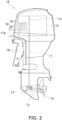
- FIG. 2 is a side view of the first marine propulsion device 1A.
- the first marine propulsion device 1A includes an engine 10, a drive shaft 11, a propeller shaft 12, and a shift mechanism 13.
- the engine 10 generates the thrust for propelling the watercraft 100.
- the engine 10 includes a crankshaft 14.
- the crankshaft 14 extends in the vertical direction.
- the drive shaft 11 is connected to the crankshaft 14.
- the drive shaft 11 extends in the vertical direction.
- the drive shaft 11 extends downward from the engine 10.
- the first marine propulsion device 1A includes a first ECU (Engine Control Unit) 17A.
- the first ECU 17A is an electronic control device for controlling the engine 10.
- the first ECU 17A includes a processor 18 such as a CPU (Central Processing Unit), a RAM (Random Access Memory) 19, and a flash ROM (Read Only Memory) 20.
- the flash ROM 20 stores programs for controlling the engine 10.
- the first ECU 17A is programmed to electrically control the engine 10.
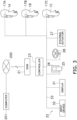
- FIG. 3 is a schematic diagram showing a configuration of a watercraft system installed in the watercraft 100.
- the second marine propulsion device 1B includes a second ECU 17B.
- the third marine propulsion device 1C includes a third ECU 17C.
- Each of the second and third ECUs 17B and 17C is similar in configuration and function to the first ECU 17A.
- the other constituent elements in each of the second and third marine propulsion devices 1B and 1C are similar to those in the first marine propulsion device 1A.
- the watercraft system includes a data communication module (hereinafter referred to as DCM) 21, a device system 22, and a controller 23.
- the DCM 21 performs wireless communication with an external computer 201.
- the DCM 21 is capable of performing data transmission with the external computer 201 through a mobile communication network 200.
- the mobile communication network 200 is, for instance, a network of a 3G, 4G, or 5G mobile communication system.
- the device system 22 includes electric devices installed in the watercraft 100.
- the device system 22 includes the first to third ECUs 17A to 17C described above.
- the device system 22 includes a throttle-shift operating device 25.
- the throttle-shift operating device 25 is operable by an operator to regulate the rotational speed of the engine 10 in each of the first to third marine propulsion devices 1A to 1C.
- the throttle-shift operating device 25 is operable by the operator to perform switching between a forward moving action and a rearward moving action by each of the first to third marine propulsion devices 1Ato 1C.
- the throttle-shift operating device 25 includes a throttle lever 26.
- the throttle lever 26 is operable from a neutral position to a forward moving position and a rearward moving position.
- the throttle-shift operating device 25 outputs a throttle signal indicating the operating position of the throttle lever 26.
- Each ECU 17A, 17B, 17C receives the throttle signal from the throttle-shift operating device 25.
- Each ECU 17A, 17B, 17C controls the shift mechanism 13 relevant thereto in accordance with the operating position of the throttle lever 26. Accordingly, the rotational direction of the propeller shaft 12 relevant thereto is switched between a forward moving direction and a rearward moving direction.
- each ECUs 17A, 17B, 17C controls the rotational speed of the engine 10 relevant thereto depending on the operating position of the throttle lever 26.
- the device system 22 includes a steering actuator 27 and a steering operating device 28.
- the steering actuator 27 turns each marine propulsion device 1A, 1B, 1C right and left so as to change the rudder angle of each marine propulsion device 1A, 1B, 1C.
- the steering actuator 27 is, for instance, an electric motor.
- the steering actuator 27 may include an electric pump and a hydraulic cylinder.
- the steering operating device 28 is operable by the operator to adjust the rudder angle of each marine propulsion device 1A, 1B, 1C.
- the steering operating device 28 is, for instance, a steering wheel. Alternatively, the steering operating device 28 may be another type of operating device such as a joystick.
- the steering operating device 28 is operable right and left from a neutral position.
- the steering operating device 28 outputs a steering signal indicating the operating position thereof.
- the steering actuator 27 is controlled depending on the operating position of the steering operating device 28, whereby the rudder angle of each marine propulsion device 1A, 1B, 1C is controlled.
- the device system 22 includes a display 31 and an input device 32.
- the display 31 displays information regarding each marine propulsion device 1A, 1B, 1C.
- the display 31 displays an image in accordance with an image signal inputted thereto.
- the input device 32 receives an operational input by a user.
- the input device 32 outputs an input signal indicating the operational input by the user.
- the input device 32 is, for instance, a touchscreen. However, the input device 32 may include at least one hardware key.
- the device system 22 includes a CAN (Controller Area Network) 33.
- the CAN 33 is a communication network that the electric devices, included in the device system 22, are connected therethrough to each other.
- the controller 23 includes a processor such as a CPU and memories such as a RAM and a ROM.
- the controller 23 controls the device system 22.
- the controller 23 controls the device system 22 in accordance with the input signal transmitted thereto from the input device 32.
- the controller 23 outputs the image signal to the display 31 so as to cause the display 31 to display a desired image.
- the device system 22 is connected to the DCM 21 through the controller 23.
- a computer 201 is connected to the CAN 33 through the DCM 21.
- the computer 201 rewrites a program of each ECU 17A, 17B, 17C by utilizing a protocol for rewriting the program such as UDS (Unified Diagnostic Services).
- UDS Unified Diagnostic Services
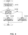
- FIG. 4 is a flowchart showing a series of processing executed by the computer 201 to rewrite the program of each ECU 17A, 17B, 17C.
- the computer 201 obtains ECU information from each ECU 17A, 17B, 17C.
- the ECU information includes the protocol version, the frequency of rewriting the program, and the serial number of each ECU 17A, 17B, 17C.
- the computer 201 herein obtains the ECU information by another communication protocol different from the rewriting protocol in the CAN 33 described above.
- IDs are set for a plurality of ECUs so as to distinguish the ECUs from one another even when the ECUs are of an identical type.
- SAE J1939 may be employed as another communication protocol herein described. This is because, when receiving multiple packet responses from the ECUs 17A to 17C in communication under the rewriting protocol, the computer 201 cannot correctly distinguish the responses from the ECUs 17A to 17C from one another.
- step S102 the computer 201 determines whether or not each ECU 17A, 17B, 17C is compatible with batch rewriting.
- the computer 201 determines whether or not each ECU 17A, 17B, 17C is compatible with the batch rewriting based on the version of the protocol of each ECU 17A, 17B, 17C.
- step S103 the computer 201 transmits data for rewriting the program of each ECU 17A, 17B, 17C to each ECU 17A, 17B, 17C with a common identifier for the batch rewriting.
- the common identifier has been preliminarily set to each ECU 17A, 17B, 17C having a protocol version compatible with the batch rewriting.
- step S104 the computer 201 transmits the data for rewriting the program to each ECU 17A, 17B, 17C with a unique identifier for discrete rewriting.
- the unique identifier has been preliminarily assigned and set to each ECU 17A, 17B, 17C having a protocol version incompatible with the batch rewriting.
- the computer 201 when determining that the first and second ECUs 17A and 17B are compatible with the batch rewriting, the computer 201 simultaneously transmits the data for rewriting the program to the first and second ECUs 17A and 17B with an identifier common to the first and second ECUs 17A and 17B.
- the computer 201 when determining that the third ECU 17C is incompatible with the batch rewriting, the computer 201 transmits the data for rewriting the program to the third ECU 17C with an identifier uniquely assigned to the third ECU 17C. In other words, the computer 201 separately executes data transmission to the first and second ECUs 17A and 17B with the common identifier and data transmission to the third ECU 17C with the unique identifier.
- the computer 201 when determining that all the first to third ECUs 17A to 17C are compatible with the batch rewriting, the computer 201 simultaneously transits the data for rewriting the program to the first to third ECUs 17A to 17C with an identifier common to the first to third ECUs 17A to 17C. Contrarily, when determining that all the first to third ECUs 17A to 17C are incompatible with the batch rewriting, the computer 201 sequentially transmits the data for rewriting the program to the first to third ECUs 17A to 17C with identifiers uniquely assigned to the first to third ECUs 17A to 17C, respectively.
- the computer 201 executes a series of processing shown in FIG. 5 to transmit data to the given ECUs with an identifier common to the given ECUs.
- the first and second ECUs 17A and B are compatible with the batch rewriting, whereas the third ECU 17C is incompatible with the batch rewriting.
- step S201 the computer 201 transmits a request to proceed to an extensive diagnostic session to each ECU 17A, 17B.
- the computer 201 transmits a request to proceed to a reprogramming session to each ECU 17A, 17B.
- step S203 the computer 201 transmits "Seed” for secure access to each ECU 17A, 17B.
- step S204 the computer 201 transmits "Key” for secure access to each ECU 17A, 17B.
- the Key is processed as an error in a given ECU other than each ECU 17A, 17B associated with the Key; hence, the number of Keys transmitted from the computer 201 is equal to the number of the ECUs 17A and 17B associated with the Keys.
- the ECUs 17A and 17B allow errors to occur at a frequency of "the number of ECUs - 1".
- step S205 the computer 201 transmits a command to update the frequency of rewriting.
- the computer 201 transmits, not a specific value of frequency, but a command to increase by one the frequency of rewriting, to each ECU 17A, 17B.
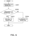
- FIG. 6 is a flowchart showing a series of processing executed by each ECU 17A, 17B when each ECU 17A, 17B receives the command to update the frequency of rewriting. For example, suppose the first ECU 17A receives the command to update the frequency of rewriting. As shown in FIG. 6 , the first ECU 17A increases by one the frequency of rewriting executed therein in step S301. When the upper limit is set for the frequency of rewriting in the ECU 17A, the first ECU 17A determines whether or not the frequency of rewriting is greater than a set value A1 in step S302.
- step S303 the first ECU 17A refuses to rewrite the program.
- the first ECU 17A transmits a negative response to the computer 201.
- the computer 201 determines that the program is not rewritable in the first ECU 17A.
- step S304 the first ECU 17A accepts rewriting of the program. In this case, the first ECU 17A transmits a positive response to the computer 201. It should be noted that, even when the upper limit is not set for the frequency of rewriting in the first ECU 17A, the first ECU 17A transmits the positive response to the computer 201. When receiving the positive response from the first ECU 17A, the computer 201 determines that the program is rewritable in the first ECU 17A. Likewise, the second ECU 17B executes the series of processing described above, when receiving the command to update the frequency of rewriting.
- step S206 the computer 201 transmits a command to erase the flash ROM to each ECU 17A, 17B. It should be noted that a given ECU, in which the program is not rewritable, transmits a negative response with respect to the series of processing in step S206 and thereafter, whereas only another ECU, in which the program is rewritable, continues executing the series of processing in step S206 and thereafter.
- step S207 the computer 201 transmits a download request to each ECU 17A, 17B.
- the computer 201 executes data transfer in accordance with the loosest one of the conditions obtained from the responses.
- each ECU 17A, 17B transmits a response based on the volume of data transmission declared by the computer 201.
- the computer 201 does not execute processing depending on a value requested by each ECU 17A, 17B.
- step S208 the computer 201 transmits updated program data to each ECU 17A, 17B.
- Each ECU 17A, 17B rewrites the program based on the received program data. For example, when accepting to rewrite the program, the first ECU 17A rewrites the program based on the program data received from the computer 201. When refusing to rewrite the program, the first ECU 17A does not rewrite the program.
- the computer 201 transmits a checksum verification to each ECU 17A, 17B in step S209.
- the computer 201 transmits a reboot command to each ECU 17A, 17B.
- the computer 201 transmits a request to proceed to an extensive diagnostic session to each ECU 17A, 17B.
- the computer 201 transmits a request to proceed to a default session to each ECU 17A, 17B.
- step S213 the computer 201 transmits an ECU information request to each ECU 17A, 17B.
- the computer 201 herein obtains the ECU information with another communication protocol different from the rewriting protocol in the CAN 33.
- each ECU 17A, 17B transmits a response with respect to each processing described above; then, the computer 201 executes the following processing after receiving the response from each ECU 17A, 17B.
- the computer 201 determines that the program is not rewritable in the ECU in which any kind of error occurs but continues executing the batch rewriting.
- the computer 201 executes the batch rewriting till the end.
- the computer 201 executes the series of processing with respect to the given ECU till the end of rewriting. Accordingly, occurrence of damage or breakage of software can be inhibited in each ECU 17A, 17B.
- the computer 201 transmits data to the third ECU 17C incompatible with the batch rewriting with an identifier uniquely assigned to the third ECU 17C in a series of processing similar to that described above.
- the data for rewriting the program are transmitted to each of the plural ECUs 17A and 17B with the common identifier through the CAN 33. Because of this, rewriting of the program is simultaneously executed with respect to the ECUs 17A and 17B compatible with the batch rewriting. This results in reduction in length of time required for rewriting the programs of the plural ECUs 17A and 17B.
- the plural ECUs 17A to 17C include not only one or more ECUs compatible with the batch rewriting but also one or more ECUs incompatible with the batch rewriting, the discrete rewriting of the program can be executed with respect to the one or more ECUs incompatible with the batch rewriting.
- Each of the plural ECUs 17A and 17B determines whether or not to rewrite the program thereof. Because of this, the computer 201 is not required to determine whether or not to rewrite the program in each of the plural ECUs 17A and 17B; hence, the processing to be executed by the computer 201 is simplified.
- Each marine propulsion device 1A, 1B, 1C is not limited to the outboard motor, and alternatively, may be another type of propulsion device such as an inboard engine outboard drive or a jet propulsion device.
- the structure of each marine propulsion device 1A, 1B, 1C is not limited to that in the preferred embodiment described above and may be changed.
- each marine propulsion device 1A, 1B, 1C may include an electric motor instead of the engine.
- the number of marine propulsion devices is not limited to three.
- the number of marine propulsion devices may be two or may be more than three.
- the electronic control device is not limited to the ECU described above and may be changed.
- the electronic control device may be a motor controller for controlling the electric motor.
- the condition for rewriting the program is not limited to that the frequency of rewriting the program has not reached the set value.
- Another condition may be set as an additional condition for rewriting the program.
- a condition that at least one of the marine propulsion devices is not in operation or a condition that a voltage applied to each ECU is greater than or equal to a predetermined value may be set as an additional condition for rewriting the program.
- the computer 201 is connected to the CAN 33 through the mobile communication network 200.
- the computer 201 may be connected to the CAN 33 through a wired communication or a short-range wireless communication including a WLAN (wireless local area network), Bluetooth (registered trademark), or so forth.
- WLAN wireless local area network
- Bluetooth registered trademark
Landscapes
- Engineering & Computer Science (AREA)
- Software Systems (AREA)
- General Engineering & Computer Science (AREA)
- Theoretical Computer Science (AREA)
- Physics & Mathematics (AREA)
- General Physics & Mathematics (AREA)
- Chemical & Material Sciences (AREA)
- Combustion & Propulsion (AREA)
- Mechanical Engineering (AREA)
- Ocean & Marine Engineering (AREA)
- Computer Security & Cryptography (AREA)
- Stored Programmes (AREA)
Abstract
Description
- The present invention relates to a method of rewriting programs of a plurality of electronic devices in a watercraft system and also relates to a watercraft system.
- A marine propulsion device such as an outboard motor is mounted to a watercraft. The marine propulsion device includes an electronic control device. The electronic control device is connected to a communication network such as a CAN (Controller Area Network). For example, as described in
Japan Laid-open Patent Application Publication No. JP 2020-179748 A - There is a type of watercraft provided with a system including a plurality of marine propulsion devices. In the system described herein, a plurality of electronic control devices of the plurality of marine propulsion devices are connected to each other through a communication network. The electronic control devices are identical in function to each other but are identified as discrete devices in the communication network. Because of this, identifiers are uniquely assigned to the electronic control devices, respectively.
- In the system including the marine propulsion devices as described above, when the programs of the electronic control devices are rewritten, the computer is configured to rewrite the programs of the electronic control devices, separately. Because of this, a length of time required for rewriting the programs inevitably increases with increase in number of the electronic control devices.
- It is an object of the present invention to reduce a length of time required for rewriting programs of a plurality of electronic control devices in a system for a watercraft including a plurality of marine propulsion devices.
- A method according to an aspect of the present invention relates to a method of rewriting a program of a first electronic control device and a program of a second electronic control device in a watercraft system. The watercraft system includes a first marine propulsion device, a second marine propulsion device, and a communication network. The first marine propulsion device includes the first electronic control device. The second marine propulsion device includes the second electronic control device. The communication network connects the first electronic control device and the second electronic control device therethrough. The method includes transmitting data for rewriting each of the programs to each of the first and second electronic control devices with a common identifier through the communication network, causing the first electronic control device to determine whether or not to rewrite the program thereof and then either causing the first electronic control device to execute rewriting the program thereof when the first electronic control device determines to rewrite the program thereof or causing the first electronic control device not to execute rewriting the program thereof when the first electronic control device determines not to rewrite the program thereof, and causing the second electronic control device to determine whether or not to rewrite the program thereof and then either causing the second electronic control device to execute rewriting the program thereof when the second electronic control device determines to rewrite the program thereof or causing the second electronic control device not to execute rewriting the program thereof when the second electronic control device determines not to rewrite the program thereof.
- A watercraft system according to another aspect of the present invention includes a first marine propulsion device, a second marine propulsion device, a communication network, and a computer. The first marine propulsion device includes a first electronic control device. The second marine propulsion device includes a second electronic control device. The communication network connects the first electronic control device and the second electronic control device therethrough. The computer is connected to the communication network and rewrites a program of the first electronic control device and a program of the second electronic control device. The computer transmits data for rewriting each of the programs to each of the first and second electronic control devices with a common identifier through the communication network. The first electronic control device receives the data and determines whether or not to rewrite the program thereof The first electronic control device executes rewriting the program thereof when determining to rewrite the program thereof but does not execute rewriting the program thereof when determining not to rewrite the program thereof. The second electronic control device receives the data and determines whether or not to rewrite the program thereof The second electronic control device executes rewriting the program thereof when determining to rewrite the program thereof but does not execute rewriting the program thereof when determining not to rewrite the program thereof.
- According to the present invention, the data for rewriting each of the programs are transmitted to each of the plural electronic control devices with the common identifier through the communication network. This results in reduction in length of time required for rewriting the programs of the plural electronic control devices. Besides, each of the plural electronic control devices determines whether or not to rewrite the program thereof. Because of this, the computer for rewriting the programs is not required to determine whether or not to rewrite the program in each of the plural electronic control devices; hence, the processing to be executed by the computer is simplified.
-
-
FIG. 1 is a schematic diagram showing a watercraft according to a preferred embodiment. -
FIG. 2 is a side view of a marine propulsion device. -
FIG. 3 is a schematic diagram showing a control system for the watercraft. -
FIG. 4 is a flowchart showing a series of processing executed by a computer to rewrite a program of an ECU (Engine Control Unit). -
FIG. 5 is a flowchart showing a series of processing executed by the computer to rewrite the program of the ECU. -
FIG. 6 is a flowchart showing a series of processing executed by the ECU when the ECU receives a command to update the frequency of rewriting. - A preferred embodiment will be hereinafter explained with reference to drawings.
FIG. 1 is a perspective view of awatercraft 100 according to the preferred embodiment. A plurality of marinepropulsion devices 1Ato 1C are attached to the stem ofthewatercraft 100. Each ofthemarine propulsion devices 1A to 1C generates a thrust for propelling thewatercraft 100. In the present preferred embodiment, themarine propulsion devices 1A to 1C are outboard motors. The marine propulsion devices 1Ato 1C include a firstmarine propulsion device 1A, a second marine propulsion device 1B, and a thirdmarine propulsion device 1C. -
FIG. 2 is a side view of the firstmarine propulsion device 1A. As shown inFIG. 2 , the firstmarine propulsion device 1A includes anengine 10, adrive shaft 11, apropeller shaft 12, and ashift mechanism 13. Theengine 10 generates the thrust for propelling thewatercraft 100. Theengine 10 includes acrankshaft 14. Thecrankshaft 14 extends in the vertical direction. Thedrive shaft 11 is connected to thecrankshaft 14. Thedrive shaft 11 extends in the vertical direction. Thedrive shaft 11 extends downward from theengine 10. - The
propeller shaft 12 extends in the back-and-forth direction ofthe firstmarine propulsion device 1A. Thepropeller shaft 12 is connected to thedrive shaft 11 through theshift mechanism 13. Apropeller 15 is connected to thepropeller shaft 12. Theshift mechanism 13 switches the rotational direction of mechanical power to be transmitted from thedrive shaft 11 to thepropeller shaft 12. Theshift mechanism 13 includes, for instance, a plurality of gears and a clutch that changes meshing of the gears. The firstmarine propulsion device 1A is attached to thewatercraft 100 through abracket 16. - The first
marine propulsion device 1A includes a first ECU (Engine Control Unit) 17A. The first ECU 17A is an electronic control device for controlling theengine 10. The first ECU 17A includes aprocessor 18 such as a CPU (Central Processing Unit), a RAM (Random Access Memory) 19, and a flash ROM (Read Only Memory) 20. Theflash ROM 20 stores programs for controlling theengine 10. The first ECU 17Ais programmed to electrically control theengine 10. -
FIG. 3 is a schematic diagram showing a configuration of a watercraft system installed in thewatercraft 100. As shown inFIG. 3 , the second marine propulsion device 1B includes asecond ECU 17B. The thirdmarine propulsion device 1C includes athird ECU 17C. Each of the second andthird ECUs first ECU 17A. The other constituent elements in each of the second and thirdmarine propulsion devices 1B and 1C are similar to those in the firstmarine propulsion device 1A. - As shown in
FIG. 3 , the watercraft system includes a data communication module (hereinafter referred to as DCM) 21, adevice system 22, and acontroller 23. TheDCM 21 performs wireless communication with anexternal computer 201. For example, theDCM 21 is capable of performing data transmission with theexternal computer 201 through amobile communication network 200. Themobile communication network 200 is, for instance, a network of a 3G, 4G, or 5G mobile communication system. - The
device system 22 includes electric devices installed in thewatercraft 100. For example, thedevice system 22 includes the first tothird ECUs 17A to 17C described above. Thedevice system 22 includes a throttle-shift operating device 25. The throttle-shift operating device 25 is operable by an operator to regulate the rotational speed of theengine 10 in each of the first to thirdmarine propulsion devices 1A to 1C. Besides, the throttle-shift operating device 25 is operable by the operator to perform switching between a forward moving action and a rearward moving action by each of the first to third marinepropulsion devices 1Ato 1C. - The throttle-
shift operating device 25 includes athrottle lever 26. Thethrottle lever 26 is operable from a neutral position to a forward moving position and a rearward moving position. The throttle-shift operating device 25 outputs a throttle signal indicating the operating position of thethrottle lever 26. EachECU shift operating device 25. EachECU shift mechanism 13 relevant thereto in accordance with the operating position of thethrottle lever 26. Accordingly, the rotational direction of thepropeller shaft 12 relevant thereto is switched between a forward moving direction and a rearward moving direction. Besides, eachECUs engine 10 relevant thereto depending on the operating position of thethrottle lever 26. - The
device system 22 includes asteering actuator 27 and asteering operating device 28. The steeringactuator 27 turns eachmarine propulsion device marine propulsion device actuator 27 is, for instance, an electric motor. Alternatively, the steeringactuator 27 may include an electric pump and a hydraulic cylinder. - The
steering operating device 28 is operable by the operator to adjust the rudder angle of eachmarine propulsion device steering operating device 28 is, for instance, a steering wheel. Alternatively, thesteering operating device 28 may be another type of operating device such as a joystick. Thesteering operating device 28 is operable right and left from a neutral position. Thesteering operating device 28 outputs a steering signal indicating the operating position thereof. The steeringactuator 27 is controlled depending on the operating position of thesteering operating device 28, whereby the rudder angle of eachmarine propulsion device - The
device system 22 includes adisplay 31 and aninput device 32. Thedisplay 31 displays information regarding eachmarine propulsion device display 31 displays an image in accordance with an image signal inputted thereto. Theinput device 32 receives an operational input by a user. Theinput device 32 outputs an input signal indicating the operational input by the user. Theinput device 32 is, for instance, a touchscreen. However, theinput device 32 may include at least one hardware key. Thedevice system 22 includes a CAN (Controller Area Network) 33. TheCAN 33 is a communication network that the electric devices, included in thedevice system 22, are connected therethrough to each other. - The
controller 23 includes a processor such as a CPU and memories such as a RAM and a ROM. Thecontroller 23 controls thedevice system 22. For example, thecontroller 23 controls thedevice system 22 in accordance with the input signal transmitted thereto from theinput device 32. Thecontroller 23 outputs the image signal to thedisplay 31 so as to cause thedisplay 31 to display a desired image. Thedevice system 22 is connected to theDCM 21 through thecontroller 23. - A
computer 201 is connected to theCAN 33 through theDCM 21. Thecomputer 201 rewrites a program of eachECU ECU -
FIG. 4 is a flowchart showing a series of processing executed by thecomputer 201 to rewrite the program of eachECU FIG. 4 , in step S101, thecomputer 201 obtains ECU information from eachECU ECU computer 201 herein obtains the ECU information by another communication protocol different from the rewriting protocol in theCAN 33 described above. In another communication protocol herein described, IDs are set for a plurality of ECUs so as to distinguish the ECUs from one another even when the ECUs are of an identical type. For instance, SAE J1939 may be employed as another communication protocol herein described. This is because, when receiving multiple packet responses from theECUs 17A to 17C in communication under the rewriting protocol, thecomputer 201 cannot correctly distinguish the responses from theECUs 17A to 17C from one another. - In step S102, the
computer 201 determines whether or not eachECU computer 201 determines whether or not eachECU ECU - When each
ECU computer 201 transmits data for rewriting the program of eachECU ECU ECU - When each
ECU computer 201 transmits the data for rewriting the program to eachECU ECU - For example, when determining that the first and
second ECUs computer 201 simultaneously transmits the data for rewriting the program to the first andsecond ECUs second ECUs third ECU 17C is incompatible with the batch rewriting, thecomputer 201 transmits the data for rewriting the program to thethird ECU 17C with an identifier uniquely assigned to thethird ECU 17C. In other words, thecomputer 201 separately executes data transmission to the first andsecond ECUs third ECU 17C with the unique identifier. - Alternatively, when determining that all the first to
third ECUs 17A to 17C are compatible with the batch rewriting, thecomputer 201 simultaneously transits the data for rewriting the program to the first tothird ECUs 17A to 17C with an identifier common to the first tothird ECUs 17A to 17C. Contrarily, when determining that all the first tothird ECUs 17A to 17C are incompatible with the batch rewriting, thecomputer 201 sequentially transmits the data for rewriting the program to the first tothird ECUs 17A to 17C with identifiers uniquely assigned to the first tothird ECUs 17A to 17C, respectively. - When given ECUs are compatible with the batch rewriting, the
computer 201 executes a series of processing shown inFIG. 5 to transmit data to the given ECUs with an identifier common to the given ECUs. In the following explanation, it is assumed that the first andsecond ECUs 17A and B are compatible with the batch rewriting, whereas thethird ECU 17C is incompatible with the batch rewriting. - As shown in
FIG. 5 , in step S201, thecomputer 201 transmits a request to proceed to an extensive diagnostic session to eachECU computer 201 transmits a request to proceed to a reprogramming session to eachECU - In step S203, the
computer 201 transmits "Seed" for secure access to eachECU computer 201 transmits "Key" for secure access to eachECU ECU computer 201 is equal to the number of theECUs ECUs - In step S205, the
computer 201 transmits a command to update the frequency of rewriting. Thecomputer 201 transmits, not a specific value of frequency, but a command to increase by one the frequency of rewriting, to eachECU -
FIG. 6 is a flowchart showing a series of processing executed by eachECU ECU first ECU 17A receives the command to update the frequency of rewriting. As shown inFIG. 6 , thefirst ECU 17A increases by one the frequency of rewriting executed therein in step S301. When the upper limit is set for the frequency of rewriting in theECU 17A, thefirst ECU 17A determines whether or not the frequency of rewriting is greater than a set value A1 in step S302. - When the
first ECU 17A determines that the frequency of rewriting is greater than the set value A1 in step S302, the processing proceeds to step S303. In step S303, thefirst ECU 17A refuses to rewrite the program. In this case, thefirst ECU 17A transmits a negative response to thecomputer 201. When receiving the negative response from thefirst ECU 17A, thecomputer 201 determines that the program is not rewritable in thefirst ECU 17A. - When the
first ECU 17A determines that the frequency of rewriting is not greater than the set value A1 in step S302, the processing proceeds to step S304. In step S304, thefirst ECU 17A accepts rewriting of the program. In this case, thefirst ECU 17A transmits a positive response to thecomputer 201. It should be noted that, even when the upper limit is not set for the frequency of rewriting in thefirst ECU 17A, thefirst ECU 17A transmits the positive response to thecomputer 201. When receiving the positive response from thefirst ECU 17A, thecomputer 201 determines that the program is rewritable in thefirst ECU 17A. Likewise, thesecond ECU 17B executes the series of processing described above, when receiving the command to update the frequency of rewriting. - In step S206, the
computer 201 transmits a command to erase the flash ROM to eachECU - In step S207, the
computer 201 transmits a download request to eachECU ECUs 17Aand 17B (e.g., a difference in volume of acceptable data or a difference in request for intervals of communication time), thecomputer 201 executes data transfer in accordance with the loosest one of the conditions obtained from the responses. Besides, eachECU computer 201. In short, thecomputer 201 does not execute processing depending on a value requested by eachECU - In step S208, the
computer 201 transmits updated program data to eachECU ECU first ECU 17A rewrites the program based on the program data received from thecomputer 201. When refusing to rewrite the program, thefirst ECU 17A does not rewrite the program. - When transmission of the program data is completed, the
computer 201 transmits a checksum verification to eachECU computer 201 transmits a reboot command to eachECU computer 201 transmits a request to proceed to an extensive diagnostic session to eachECU computer 201 transmits a request to proceed to a default session to eachECU - In step S213, the
computer 201 transmits an ECU information request to eachECU computer 201 herein obtains the ECU information with another communication protocol different from the rewriting protocol in theCAN 33. - It should be noted that each
ECU computer 201 executes the following processing after receiving the response from eachECU ECU 17A or theECU 17B in the series of processing executed before the processing step of erasing the flash ROM, thecomputer 201 determines that the program is not rewritable in the ECU in which any kind of error occurs but continues executing the batch rewriting. On the other hand, even when any kind of error occurs in either theECU 17A or theECU 17B in the series of processing at and after the processing step of erasing the flash ROM, thecomputer 201 executes the batch rewriting till the end. In other words, when a given ECU has a chance of success of rewriting, thecomputer 201 executes the series of processing with respect to the given ECU till the end of rewriting. Accordingly, occurrence of damage or breakage of software can be inhibited in eachECU - The
computer 201 transmits data to thethird ECU 17C incompatible with the batch rewriting with an identifier uniquely assigned to thethird ECU 17C in a series of processing similar to that described above. - In the watercraft system according to the present preferred embodiment explained above, the data for rewriting the program are transmitted to each of the
plural ECUs CAN 33. Because of this, rewriting of the program is simultaneously executed with respect to theECUs plural ECUs plural ECUs 17A to 17C include not only one or more ECUs compatible with the batch rewriting but also one or more ECUs incompatible with the batch rewriting, the discrete rewriting of the program can be executed with respect to the one or more ECUs incompatible with the batch rewriting. - Each of the
plural ECUs computer 201 is not required to determine whether or not to rewrite the program in each of theplural ECUs computer 201 is simplified. - One preferred embodiment of the present invention has been explained above. However, the present invention is not limited to the preferred embodiment described above, and a variety of changes can be made without departing from the gist of the present invention.
- Each
marine propulsion device marine propulsion device marine propulsion device - The number of marine propulsion devices is not limited to three. The number of marine propulsion devices may be two or may be more than three. The electronic control device is not limited to the ECU described above and may be changed. For example, when each marine propulsion device includes an electric motor as a drive source, the electronic control device may be a motor controller for controlling the electric motor.
- The condition for rewriting the program is not limited to that the frequency of rewriting the program has not reached the set value. Another condition may be set as an additional condition for rewriting the program. For example, a condition that at least one of the marine propulsion devices is not in operation or a condition that a voltage applied to each ECU is greater than or equal to a predetermined value may be set as an additional condition for rewriting the program.
- In the preferred embodiment described above, the
computer 201 is connected to theCAN 33 through themobile communication network 200. However, thecomputer 201 may be connected to theCAN 33 through a wired communication or a short-range wireless communication including a WLAN (wireless local area network), Bluetooth (registered trademark), or so forth. -
- 1A
- First marine propulsion device
- 1B
- Second marine propulsion device
- 1C
- Third marine propulsion device
- 17A
- First ECU
- 17B
- Second ECU
- 17C
- Third ECU
- 33
- CAN
- 201
- Computer
Claims (10)
- A method of rewriting a program of a first electronic control device (17A) and a program of a second electronic control device (17B) in a watercraft system, the watercraft system including a first marine propulsion device (1A), a second marine propulsion device (1B), and a communication network (33), the first marine propulsion device (1A) including the first electronic control device (17A), the second marine propulsion device (1B) including the second electronic control device (17B), the communication network (33) connecting the first electronic control device (17A) and the second electronic control device (17B) therethrough, the method comprising:transmitting data for rewriting each of the programs to each of the first and second electronic control devices (17A, 17B) with a common identifier through the communication network (33);causing the first electronic control device (17A) to determine whether or not to rewrite the program thereof and then either causing the first electronic control device (17A) to execute rewriting the program thereof when the first electronic control device (17A) determines to rewrite the program thereof or causing the first electronic control device (17A) not to execute rewriting the program thereof when the first electronic control device (17A) determines not to rewrite the program thereof; andcausing the second electronic control device (17B) to determine whether or not to rewrite the program thereof and then either causing the second electronic control device (17B) to execute rewriting the program thereof when the second electronic control device (17B) determines to rewrite the program thereof or causing the second electronic control device (17B) not to execute rewriting the program thereof when the second electronic control device (17B) determines not to rewrite the program thereof.
- The method according to claim 1, wherein
the watercraft system further includes a third marine propulsion device (1C), the third marine propulsion device (1C) including a third electronic control device (17C), the method further comprising:determining whether or not each of the first, second, and third electronic control devices (17A, 17B, 17C) is compatible with batch rewriting of the program of the first electronic control device (17A), the program of the second electronic control device (17B), and a program of the third electronic control device (17C) with the common identifier;transmitting the data for rewriting the each of the programs to the each of the first and second electronic control devices (17A, 17B) with the common identifier when the first and second electronic control devices (17A, 17B) are determined to be compatible with the batch rewriting; andtransmitting data for rewriting the program of the third electronic control device (17C) to the third electronic control device (17C) with an identifier uniquely assigned to the third electronic control device (17C) so as to be different from the common identifier when the third electronic control device (17C) is determined to be incompatible with the batch rewriting. - The method according to claim 2, further comprising:obtaining a version of a protocol for rewriting each of the programs of the first, second, and third electronic control devices (17A, 17B, 17C) from the each of the first, second, and third electronic control devices (17A, 17B, 17C); anddetermining whether or not the each of the first, second, and third electronic control devices (17A, 17B, 17C) is compatible with the batch rewriting based on the version of the protocol thereof.
- The method according to claim 1, further comprising:causing the each of the first and second electronic control devices (17A, 17B) to determine whether or not a predetermined rewriting condition is satisfied therein;causing the each of the first and second electronic control devices (17A, 17B) to determine to rewrite the program thereof when the predetermined rewriting condition is satisfied therein; andcausing the each of the first and second electronic control devices (17A, 17B) to determine not to rewrite the program thereof when the predetermined rewriting condition is not satisfied therein.
- The method according to claim 4, wherein the predetermined rewriting condition is one of a plurality of rewriting conditions including that a frequency of rewriting the each of the programs has not reached a set value.
- A watercraft system comprising:a first marine propulsion device (1A) including a first electronic control device (17A);a second marine propulsion device (1B) including a second electronic control device (17B);a communication network (33) connecting the first electronic control device (17A) and the second electronic control device (17B) therethrough; anda computer (201) connected to the communication network (33), the computer (201) being configured to rewrite a program of the first electronic control device (17A) and a program of the second electronic control device (17B), whereinthe computer (201) is configured to transmit data for rewriting each of the programs to each of the first and second electronic control devices (17A, 17B) with a common identifier through the communication network (33),the first electronic control device (17A) is configured toreceive the data,determine whether or not to rewrite the program thereof,execute rewriting the program thereof when determining to rewrite the program thereof,refuse rewriting the program thereof when determining not to rewrite the program thereof, andthe second electronic control device (17B) is configured toreceive the data,determine whether or not to rewrite the program thereof,execute rewriting the program thereof when determining to rewrite the program thereof,refuse rewriting the program thereof when determining not to rewrite the program thereof.
- The watercraft system according to claim 6, further comprising:a third marine propulsion device (1C) including a third electronic control device (17C),
whereinthe computer (201) determines whether or not each of the first, second, and third electronic control devices (17A, 17B, 17C) is compatible with batch rewriting of the program of the first electronic control device (17A), the program of the second electronic control device (17B), and a program of the third electronic control device (17C) with the common identifier,the computer (201) is configured totransmit the data for rewriting the each of the programs to the each of the first and second electronic control devices (17A, 17B) with the common identifier when determining that the first and second electronic control devices (17A, 17B) are compatible with the batch rewriting, andtransmit data for rewriting the program of the third electronic control device (17C) to the third electronic control device (17C) with an identifier uniquely assigned to the third electronic control device (17C) so as to be different from the common identifier when determining that the third electronic control device (17C) is incompatible with the batch rewriting. - The watercraft system according to claim 7, wherein
the computer (201) is configured to
obtain a version of a protocol for rewriting each of the programs of the first, second, and third electronic control devices (17A, 17B, 17C) from the each of the first, second, and third electronic control devices (17A, 17B, 17C), and determine whether or not the each of the first, second, and third electronic control devices (17A, 17B, 17C) is compatible with the batch rewriting based on the version of the protocol thereof. - The watercraft system according to claim 6, wherein
the each of the first and second electronic control devices (17A, 17B) is configured todetermine whether or not a predetermined rewriting condition is satisfied therein,determine to rewrite the program thereof when the predetermined rewriting condition is satisfied therein, anddetermine not to rewrite the program thereof when the predetermined rewriting condition is not satisfied therein. - The watercraft system according to claim 9, wherein the predetermined rewriting condition is one of a plurality of rewriting conditions including that a frequency of rewriting the each of the programs has not reached a set value.
Applications Claiming Priority (1)
| Application Number | Priority Date | Filing Date | Title |
|---|---|---|---|
| JP2022110636A JP2024008622A (en) | 2022-07-08 | 2022-07-08 | Method of rewriting programs of multiple electronic control devices in a ship system, and ship system |
Publications (2)
| Publication Number | Publication Date |
|---|---|
| EP4303721A1 true EP4303721A1 (en) | 2024-01-10 |
| EP4303721B1 EP4303721B1 (en) | 2025-07-02 |
Family
ID=86497536
Family Applications (1)
| Application Number | Title | Priority Date | Filing Date |
|---|---|---|---|
| EP23174506.8A Active EP4303721B1 (en) | 2022-07-08 | 2023-05-22 | Method of rewriting programs of plurality of electronic devices in watercraft system and watercraft system |
Country Status (3)
| Country | Link |
|---|---|
| US (1) | US20240012621A1 (en) |
| EP (1) | EP4303721B1 (en) |
| JP (1) | JP2024008622A (en) |
Citations (4)
| Publication number | Priority date | Publication date | Assignee | Title |
|---|---|---|---|---|
| US6872106B2 (en) * | 2001-10-25 | 2005-03-29 | Yamaha Marine Kabuskiki Kaisha | Propulsion unit network |
| US20050256614A1 (en) * | 2004-05-13 | 2005-11-17 | General Motors Corporation | Method and system for remote reflash |
| JP6221866B2 (en) * | 2014-03-19 | 2017-11-01 | 株式会社デンソー | Program rewriting system and electronic control unit |
| JP2020179748A (en) | 2019-04-24 | 2020-11-05 | ヤマハ発動機株式会社 | Vessel propulsion system and device and method for diagnosis of the same |
Family Cites Families (9)
| Publication number | Priority date | Publication date | Assignee | Title |
|---|---|---|---|---|
| US8539477B2 (en) * | 2009-02-24 | 2013-09-17 | Microsoft Corporation | Managed environment update selection |
| US20130110329A1 (en) * | 2011-10-31 | 2013-05-02 | Yamaha Hatsudoki Kabushiki Kaisha | Watercraft |
| US11816465B2 (en) * | 2013-03-15 | 2023-11-14 | Ei Electronics Llc | Devices, systems and methods for tracking and upgrading firmware in intelligent electronic devices |
| EP3412514B1 (en) * | 2014-11-12 | 2019-12-04 | Panasonic Intellectual Property Corporation of America | Update management method, update management device, and control program |
| JP2017084322A (en) * | 2015-10-26 | 2017-05-18 | 株式会社リコー | Information system, program, and recording medium |
| US10572240B2 (en) * | 2016-12-19 | 2020-02-25 | Vmware Inc. | Operating system update management for enrolled devices |
| KR102417004B1 (en) * | 2017-09-19 | 2022-07-07 | 삼성전자주식회사 | Method and apparatus for controlling a update of software of an electronic device |
| US11334338B2 (en) * | 2019-01-25 | 2022-05-17 | Vmware, Inc. | Operating system update management |
| WO2023280412A1 (en) * | 2021-07-08 | 2023-01-12 | Cariad Se | Electronic control unit, vehicle with an electronic control unit and method for updating an electronic control unit |
-
2022
- 2022-07-08 JP JP2022110636A patent/JP2024008622A/en active Pending
-
2023
- 2023-05-22 EP EP23174506.8A patent/EP4303721B1/en active Active
- 2023-06-13 US US18/208,906 patent/US20240012621A1/en active Pending
Patent Citations (4)
| Publication number | Priority date | Publication date | Assignee | Title |
|---|---|---|---|---|
| US6872106B2 (en) * | 2001-10-25 | 2005-03-29 | Yamaha Marine Kabuskiki Kaisha | Propulsion unit network |
| US20050256614A1 (en) * | 2004-05-13 | 2005-11-17 | General Motors Corporation | Method and system for remote reflash |
| JP6221866B2 (en) * | 2014-03-19 | 2017-11-01 | 株式会社デンソー | Program rewriting system and electronic control unit |
| JP2020179748A (en) | 2019-04-24 | 2020-11-05 | ヤマハ発動機株式会社 | Vessel propulsion system and device and method for diagnosis of the same |
Also Published As
| Publication number | Publication date |
|---|---|
| JP2024008622A (en) | 2024-01-19 |
| US20240012621A1 (en) | 2024-01-11 |
| EP4303721B1 (en) | 2025-07-02 |
Similar Documents
| Publication | Publication Date | Title |
|---|---|---|
| US7593344B2 (en) | System and method for reprogramming nodes in an automotive switch fabric network | |
| CN115190214B (en) | Scanning control system, method and computing device | |
| EP1156417B1 (en) | Method and apparatus for multi-function processing capable of performing a program dowloading using a common single connection, and a medium storing the method | |
| EP4303721B1 (en) | Method of rewriting programs of plurality of electronic devices in watercraft system and watercraft system | |
| US12449801B2 (en) | Electronic control device and method for setting control data | |
| EP4303722B1 (en) | Method of rewriting programs of plurality of electronic devices in watercraft system and watercraft system | |
| JP5966697B2 (en) | Information processing device | |
| US12077272B2 (en) | System for and method of controlling watercraft including marine propulsion device | |
| JPH11303151A (en) | Display control device for construction machinery | |
| US12327106B2 (en) | Dynamic switching of communication protocols for over-the-air vehicle updates | |
| EP3923139B1 (en) | Electronic control device and method for using non-volatile memory | |
| US12012196B2 (en) | System for and method of controlling watercraft | |
| EP3806428A1 (en) | Transformation device, transformation method and storage medium | |
| CN119781444A (en) | Dynamic matching method, device, equipment and medium for vehicle diagnosis protocol | |
| JP2022013263A (en) | On-vehicle processing device of learning data | |
| US12223828B2 (en) | System for and method of controlling watercraft | |
| JPH11120077A (en) | Use of internal and external memory | |
| JP6945672B2 (en) | Fail-safe system | |
| JP7382246B2 (en) | How to rewrite the program of vehicle control device | |
| JP2010178032A (en) | Communication system of working machine | |
| CN115070482B (en) | Servo tool magazine control method and system and electronic equipment | |
| JP4499233B2 (en) | Distributed control system | |
| KR100463850B1 (en) | Method for loading Using Distributed System Startup Loader in Private Branch Exchange | |
| KR102186040B1 (en) | How to perform interface diagnosis of vehicle diagnostic information collection device | |
| CN118805364A (en) | Communication control device, vehicle, communication control method, and communication control program |
Legal Events
| Date | Code | Title | Description |
|---|---|---|---|
| PUAI | Public reference made under article 153(3) epc to a published international application that has entered the european phase |
Free format text: ORIGINAL CODE: 0009012 |
|
| STAA | Information on the status of an ep patent application or granted ep patent |
Free format text: STATUS: THE APPLICATION HAS BEEN PUBLISHED |
|
| AK | Designated contracting states |
Kind code of ref document: A1 Designated state(s): AL AT BE BG CH CY CZ DE DK EE ES FI FR GB GR HR HU IE IS IT LI LT LU LV MC ME MK MT NL NO PL PT RO RS SE SI SK SM TR |
|
| STAA | Information on the status of an ep patent application or granted ep patent |
Free format text: STATUS: REQUEST FOR EXAMINATION WAS MADE |
|
| 17P | Request for examination filed |
Effective date: 20240527 |
|
| RBV | Designated contracting states (corrected) |
Designated state(s): AL AT BE BG CH CY CZ DE DK EE ES FI FR GB GR HR HU IE IS IT LI LT LU LV MC ME MK MT NL NO PL PT RO RS SE SI SK SM TR |
|
| P01 | Opt-out of the competence of the unified patent court (upc) registered |
Free format text: CASE NUMBER: APP_37603/2024 Effective date: 20240624 |
|
| STAA | Information on the status of an ep patent application or granted ep patent |
Free format text: STATUS: EXAMINATION IS IN PROGRESS |
|
| 17Q | First examination report despatched |
Effective date: 20240918 |
|
| GRAP | Despatch of communication of intention to grant a patent |
Free format text: ORIGINAL CODE: EPIDOSNIGR1 |
|
| STAA | Information on the status of an ep patent application or granted ep patent |
Free format text: STATUS: GRANT OF PATENT IS INTENDED |
|
| RIC1 | Information provided on ipc code assigned before grant |
Ipc: B63H 21/21 20060101ALI20250306BHEP Ipc: B63H 20/00 20060101ALI20250306BHEP Ipc: G06F 8/65 20180101AFI20250306BHEP |
|
| INTG | Intention to grant announced |
Effective date: 20250321 |
|
| GRAS | Grant fee paid |
Free format text: ORIGINAL CODE: EPIDOSNIGR3 |
|
| GRAA | (expected) grant |
Free format text: ORIGINAL CODE: 0009210 |
|
| STAA | Information on the status of an ep patent application or granted ep patent |
Free format text: STATUS: THE PATENT HAS BEEN GRANTED |
|
| AK | Designated contracting states |
Kind code of ref document: B1 Designated state(s): AL AT BE BG CH CY CZ DE DK EE ES FI FR GB GR HR HU IE IS IT LI LT LU LV MC ME MK MT NL NO PL PT RO RS SE SI SK SM TR |
|
| REG | Reference to a national code |
Ref country code: GB Ref legal event code: FG4D |
|
| REG | Reference to a national code |
Ref country code: CH Ref legal event code: EP |
|
| REG | Reference to a national code |
Ref country code: DE Ref legal event code: R096 Ref document number: 602023004442 Country of ref document: DE |
|
| REG | Reference to a national code |
Ref country code: IE Ref legal event code: FG4D |
|
| REG | Reference to a national code |
Ref country code: NL Ref legal event code: MP Effective date: 20250702 |
|
| PG25 | Lapsed in a contracting state [announced via postgrant information from national office to epo] |
Ref country code: PT Free format text: LAPSE BECAUSE OF FAILURE TO SUBMIT A TRANSLATION OF THE DESCRIPTION OR TO PAY THE FEE WITHIN THE PRESCRIBED TIME-LIMIT Effective date: 20251103 |
|
| PG25 | Lapsed in a contracting state [announced via postgrant information from national office to epo] |
Ref country code: NL Free format text: LAPSE BECAUSE OF FAILURE TO SUBMIT A TRANSLATION OF THE DESCRIPTION OR TO PAY THE FEE WITHIN THE PRESCRIBED TIME-LIMIT Effective date: 20250702 |
|
| REG | Reference to a national code |
Ref country code: AT Ref legal event code: MK05 Ref document number: 1810009 Country of ref document: AT Kind code of ref document: T Effective date: 20250702 |
|
| PG25 | Lapsed in a contracting state [announced via postgrant information from national office to epo] |
Ref country code: IS Free format text: LAPSE BECAUSE OF FAILURE TO SUBMIT A TRANSLATION OF THE DESCRIPTION OR TO PAY THE FEE WITHIN THE PRESCRIBED TIME-LIMIT Effective date: 20251102 |
|
| PG25 | Lapsed in a contracting state [announced via postgrant information from national office to epo] |
Ref country code: NO Free format text: LAPSE BECAUSE OF FAILURE TO SUBMIT A TRANSLATION OF THE DESCRIPTION OR TO PAY THE FEE WITHIN THE PRESCRIBED TIME-LIMIT Effective date: 20251002 |
|
| REG | Reference to a national code |
Ref country code: LT Ref legal event code: MG9D |
|
| PG25 | Lapsed in a contracting state [announced via postgrant information from national office to epo] |
Ref country code: AT Free format text: LAPSE BECAUSE OF FAILURE TO SUBMIT A TRANSLATION OF THE DESCRIPTION OR TO PAY THE FEE WITHIN THE PRESCRIBED TIME-LIMIT Effective date: 20250702 |
|
| PG25 | Lapsed in a contracting state [announced via postgrant information from national office to epo] |
Ref country code: FI Free format text: LAPSE BECAUSE OF FAILURE TO SUBMIT A TRANSLATION OF THE DESCRIPTION OR TO PAY THE FEE WITHIN THE PRESCRIBED TIME-LIMIT Effective date: 20250702 |
|
| PG25 | Lapsed in a contracting state [announced via postgrant information from national office to epo] |
Ref country code: HR Free format text: LAPSE BECAUSE OF FAILURE TO SUBMIT A TRANSLATION OF THE DESCRIPTION OR TO PAY THE FEE WITHIN THE PRESCRIBED TIME-LIMIT Effective date: 20250702 |
|
| PG25 | Lapsed in a contracting state [announced via postgrant information from national office to epo] |
Ref country code: GR Free format text: LAPSE BECAUSE OF FAILURE TO SUBMIT A TRANSLATION OF THE DESCRIPTION OR TO PAY THE FEE WITHIN THE PRESCRIBED TIME-LIMIT Effective date: 20251003 |
|
| PG25 | Lapsed in a contracting state [announced via postgrant information from national office to epo] |
Ref country code: CZ Free format text: LAPSE BECAUSE OF FAILURE TO SUBMIT A TRANSLATION OF THE DESCRIPTION OR TO PAY THE FEE WITHIN THE PRESCRIBED TIME-LIMIT Effective date: 20250702 Ref country code: SE Free format text: LAPSE BECAUSE OF FAILURE TO SUBMIT A TRANSLATION OF THE DESCRIPTION OR TO PAY THE FEE WITHIN THE PRESCRIBED TIME-LIMIT Effective date: 20250702 |
|
| PG25 | Lapsed in a contracting state [announced via postgrant information from national office to epo] |
Ref country code: LV Free format text: LAPSE BECAUSE OF FAILURE TO SUBMIT A TRANSLATION OF THE DESCRIPTION OR TO PAY THE FEE WITHIN THE PRESCRIBED TIME-LIMIT Effective date: 20250702 |
|
| PG25 | Lapsed in a contracting state [announced via postgrant information from national office to epo] |
Ref country code: BG Free format text: LAPSE BECAUSE OF FAILURE TO SUBMIT A TRANSLATION OF THE DESCRIPTION OR TO PAY THE FEE WITHIN THE PRESCRIBED TIME-LIMIT Effective date: 20250702 Ref country code: PL Free format text: LAPSE BECAUSE OF FAILURE TO SUBMIT A TRANSLATION OF THE DESCRIPTION OR TO PAY THE FEE WITHIN THE PRESCRIBED TIME-LIMIT Effective date: 20250702 |
|
| PG25 | Lapsed in a contracting state [announced via postgrant information from national office to epo] |
Ref country code: RS Free format text: LAPSE BECAUSE OF FAILURE TO SUBMIT A TRANSLATION OF THE DESCRIPTION OR TO PAY THE FEE WITHIN THE PRESCRIBED TIME-LIMIT Effective date: 20251002 |
|
| PG25 | Lapsed in a contracting state [announced via postgrant information from national office to epo] |
Ref country code: ES Free format text: LAPSE BECAUSE OF FAILURE TO SUBMIT A TRANSLATION OF THE DESCRIPTION OR TO PAY THE FEE WITHIN THE PRESCRIBED TIME-LIMIT Effective date: 20250702 |
|
| PG25 | Lapsed in a contracting state [announced via postgrant information from national office to epo] |
Ref country code: SM Free format text: LAPSE BECAUSE OF FAILURE TO SUBMIT A TRANSLATION OF THE DESCRIPTION OR TO PAY THE FEE WITHIN THE PRESCRIBED TIME-LIMIT Effective date: 20250702 |
|
| REG | Reference to a national code |
Ref country code: DE Ref legal event code: R097 Ref document number: 602023004442 Country of ref document: DE |
|
| PG25 | Lapsed in a contracting state [announced via postgrant information from national office to epo] |
Ref country code: DK Free format text: LAPSE BECAUSE OF FAILURE TO SUBMIT A TRANSLATION OF THE DESCRIPTION OR TO PAY THE FEE WITHIN THE PRESCRIBED TIME-LIMIT Effective date: 20250702 |
|
| PG25 | Lapsed in a contracting state [announced via postgrant information from national office to epo] |
Ref country code: SK Free format text: LAPSE BECAUSE OF FAILURE TO SUBMIT A TRANSLATION OF THE DESCRIPTION OR TO PAY THE FEE WITHIN THE PRESCRIBED TIME-LIMIT Effective date: 20250702 Ref country code: EE Free format text: LAPSE BECAUSE OF FAILURE TO SUBMIT A TRANSLATION OF THE DESCRIPTION OR TO PAY THE FEE WITHIN THE PRESCRIBED TIME-LIMIT Effective date: 20250702 |
|
| PLBE | No opposition filed within time limit |
Free format text: ORIGINAL CODE: 0009261 |
|
| STAA | Information on the status of an ep patent application or granted ep patent |
Free format text: STATUS: NO OPPOSITION FILED WITHIN TIME LIMIT |
|
| REG | Reference to a national code |
Ref country code: CH Ref legal event code: L10 Free format text: ST27 STATUS EVENT CODE: U-0-0-L10-L00 (AS PROVIDED BY THE NATIONAL OFFICE) Effective date: 20260518 |
|
| 26N | No opposition filed |
Effective date: 20260407 |
|
| PG25 | Lapsed in a contracting state [announced via postgrant information from national office to epo] |
Ref country code: LT Free format text: LAPSE BECAUSE OF FAILURE TO SUBMIT A TRANSLATION OF THE DESCRIPTION OR TO PAY THE FEE WITHIN THE PRESCRIBED TIME-LIMIT Effective date: 20250702 |
|
| PGFP | Annual fee paid to national office [announced via postgrant information from national office to epo] |
Ref country code: IT Payment date: 20260601 Year of fee payment: 4 |
|
| PGFP | Annual fee paid to national office [announced via postgrant information from national office to epo] |
Ref country code: DE Payment date: 20260522 Year of fee payment: 4 |
|
| PGFP | Annual fee paid to national office [announced via postgrant information from national office to epo] |
Ref country code: FR Payment date: 20260526 Year of fee payment: 4 |