EP4303557A1 - Gas analysis device - Google Patents
Gas analysis device Download PDFInfo
- Publication number
- EP4303557A1 EP4303557A1 EP21929165.5A EP21929165A EP4303557A1 EP 4303557 A1 EP4303557 A1 EP 4303557A1 EP 21929165 A EP21929165 A EP 21929165A EP 4303557 A1 EP4303557 A1 EP 4303557A1
- Authority
- EP
- European Patent Office
- Prior art keywords
- gas
- drain
- flow path
- analysis target
- introduction space
- Prior art date
- Legal status (The legal status is an assumption and is not a legal conclusion. Google has not performed a legal analysis and makes no representation as to the accuracy of the status listed.)
- Pending
Links
Images

Classifications
-
- G—PHYSICS
- G01—MEASURING; TESTING
- G01N—INVESTIGATING OR ANALYSING MATERIALS BY DETERMINING THEIR CHEMICAL OR PHYSICAL PROPERTIES
- G01N1/00—Sampling; Preparing specimens for investigation
- G01N1/02—Devices for withdrawing samples
- G01N1/22—Devices for withdrawing samples in the gaseous state
- G01N1/2273—Atmospheric sampling
-
- G—PHYSICS
- G01—MEASURING; TESTING
- G01N—INVESTIGATING OR ANALYSING MATERIALS BY DETERMINING THEIR CHEMICAL OR PHYSICAL PROPERTIES
- G01N33/00—Investigating or analysing materials by specific methods not covered by groups G01N1/00 - G01N31/00
- G01N33/0004—Gaseous mixtures, e.g. polluted air
- G01N33/0009—General constructional details of gas analysers, e.g. portable test equipment
- G01N33/0011—Sample conditioning
- G01N33/0016—Sample conditioning by regulating a physical variable, e.g. pressure or temperature
-
- G—PHYSICS
- G01—MEASURING; TESTING
- G01N—INVESTIGATING OR ANALYSING MATERIALS BY DETERMINING THEIR CHEMICAL OR PHYSICAL PROPERTIES
- G01N1/00—Sampling; Preparing specimens for investigation
- G01N1/02—Devices for withdrawing samples
- G01N1/22—Devices for withdrawing samples in the gaseous state
- G01N1/24—Suction devices
-
- G—PHYSICS
- G01—MEASURING; TESTING
- G01N—INVESTIGATING OR ANALYSING MATERIALS BY DETERMINING THEIR CHEMICAL OR PHYSICAL PROPERTIES
- G01N1/00—Sampling; Preparing specimens for investigation
- G01N1/28—Preparing specimens for investigation including physical details of (bio-)chemical methods covered elsewhere, e.g. G01N33/50, C12Q
- G01N1/40—Concentrating samples
- G01N1/4005—Concentrating samples by transferring a selected component through a membrane
-
- G—PHYSICS
- G01—MEASURING; TESTING
- G01N—INVESTIGATING OR ANALYSING MATERIALS BY DETERMINING THEIR CHEMICAL OR PHYSICAL PROPERTIES
- G01N1/00—Sampling; Preparing specimens for investigation
- G01N1/28—Preparing specimens for investigation including physical details of (bio-)chemical methods covered elsewhere, e.g. G01N33/50, C12Q
- G01N1/42—Low-temperature sample treatment, e.g. cryofixation
-
- G—PHYSICS
- G01—MEASURING; TESTING
- G01N—INVESTIGATING OR ANALYSING MATERIALS BY DETERMINING THEIR CHEMICAL OR PHYSICAL PROPERTIES
- G01N1/00—Sampling; Preparing specimens for investigation
- G01N1/02—Devices for withdrawing samples
- G01N1/22—Devices for withdrawing samples in the gaseous state
- G01N1/2247—Sampling from a flowing stream of gas
- G01N1/2258—Sampling from a flowing stream of gas in a stack or chimney
Definitions
- the present invention relates to a gas analyzer having a drain pot.
- the exhaust gas generated in the facilities described above generally contains water vapor, and if such exhaust gas is introduced into the analyzer as it is, accurate measurement cannot be performed. Therefore, a cooler which cools the analysis target gas is provided in the gas flow path connecting a sampling point of the exhaust gas and the analyzer. When the exhaust gas is cooled in this manner, water vapor is liquefied in the cooler, and the water vapor is removed from the analysis target gas.
- the liquefied water (drain water) is introduced into a drain pot through a drain flow path (drain pipe) (for example, Patent Literature 1).
- An overflow drain pot is a water storage container having a side surface provided with a drain port which is always open to the atmosphere, and a distal end of a drain flow path extending from the cooler is disposed below the drain port in the water storage container.
- a drain port which is always open to the atmosphere
- a distal end of a drain flow path extending from the cooler is disposed below the drain port in the water storage container.
- water is always stored above the distal end of the drain flow path, and thus external gas is prevented from flowing into the gas flow path through the drain pot, the drain flow path, and the cooler.
- the amount of water in the drain pot increases due to inflow of water from the cooler, the water pours out of the drain pot from the drain port.
- a closed drain pot is a water storage container provided with a drain port having an on-off valve, and the distal end of the drain flow path extending from the cooler is inserted into the water storage container.
- the drain port may be disposed on a side wall or on a bottom of the water storage container, and the height of the distal end of the drain flow path does not depend on a height of the drain port.
- the water storage container is usually closed by closing the on-off valve, which prevents external gas from flowing into the gas flow path. Since the amount of water in the drain pot increases as the water flows in from the cooler, an operator of the facility periodically stops an operation of the gas analyzer and then opens the on-off valve to discharge the water from the drain port to the outside of the drain pot.
- Non Patent Literature 1 " SWT series”, [online], AGC Engineering Co., Ltd., [searched on June 12, 2020], Internet ⁇ URL: https://www.agec.co.jp/product/sunsep/swt.html>
- Water generated in a cooler becomes nitric acid or sulfuric acid when nitrogen oxides or sulfur oxides contained in an exhaust gas are dissolved in the water. Such water cannot be discharged outside unless appropriate treatment is performed, but in a conventional drain pot, water containing nitric acid or sulfuric acid generated in the cooler is discharged as it is.
- An object of the present invention is to provide a gas analyzer capable of facilitating the treatment of water generated from an analysis target gas and collected in a drain pot.
- a gas analyzer according to the present invention made to solve the above problems includes:
- the inside of a closed container is divided into a drain introduction space connected to a drain flow path and a gas introduction space into which a gas is introduced by a gas source by a selective permeation member configured to selectively let gas-phase water permeate.
- a gas different from the analysis target gas
- only water out of water containing nitric acid or sulfuric acid generated in a cooling unit and introduced into the drain introduction space of the closed container from a drain flow path permeates through the selective permeation member and enters the gas introduction space.
- the water that has entered the gas introduction space is taken into the gas and discharged to the outside from a gas discharge port. At that time, since the gas neither contains nitric acid nor sulfuric acid, there is no problem even if the gas is released into the environment without any treatment.
- nitric acid and sulfuric acid in the drain introduction space need to be collected periodically (for example, when a facility is stopped for maintenance), but since a frequency of collection can be reduced as compared with a case where nitric acid and sulfuric acid are collected in a state of being contained in water as in the conventional case, it is possible to reduce labor.
- a gas analyzer 10 of the present embodiment is used to measure the concentration of a predetermined substance (for example, nitrogen oxides, sulfur oxides, carbon monoxide, carbon dioxide, and oxygen) contained in an exhaust gas collected by a gas collection probe 91 attached to a gas discharge unit of an exhaust gas generation facility 90, such as a thermal power plant, a waste incineration plant, and a factory, and introduced through a pipeline 92.
- a predetermined substance for example, nitrogen oxides, sulfur oxides, carbon monoxide, carbon dioxide, and oxygen
- the gas analyzer 10 includes a gas intake port 11 and a gas analysis unit 12, which are connected by an analysis target gas flow path 13.
- a gas analysis unit 12 for example, a non-dispersive infrared (NDIR) spectrometer is used.
- an analysis target gas pump 15 is connected to the analysis target gas flow path 13.
- the gas analyzer 10 includes a cooling unit (cooler) 14 in the middle of the analysis target gas flow path 13 from the gas intake port 11 to the gas analysis unit 12.
- the analysis target gas is cooled to a predetermined temperature by the cooling unit 14 and then introduced into the gas analysis unit 12.
- a cooling unit 14 is provided in the present embodiment, an analysis target gas may be cooled in stages by arranging a plurality of cooling units.
- a drain flow path 141 is connected to the analysis target gas flow path 13.
- the drain flow path 141 extends vertically downward. Liquid (drain) such as water generated by cooling of an analysis target gas in the cooling unit 14 is discharged to a closed container 20 described later through the drain flow path 141.
- the gas analyzer 10 includes a drain separator 16 closer to the gas intake port 11 than the cooling unit 14 of the analysis target gas flow path 13 is.
- the drain separator 16 separates and collects drain generated in the analysis target gas flow path 13 at a preceding stage of the cooling unit 14 from the exhaust gas.
- the drain separator 16 is also provided with a drain flow path 161 extending vertically downward and reaching the closed container 20.
- the closed container 20 is a closed drain pot and stores drain introduced from the cooling unit 14 and the drain separator 16 through the drain flow paths 141 and 161.
- a lid 201 is provided on an upper surface of the closed container 20, and the closed container 20 is closed by the lid 201 during use of the gas analyzer 10. At the time of maintenance of the gas analyzer 10, the lid 201 is removed, and removal of liquid remaining in the closed container 20 and cleaning of the inside of the closed container 20 can be performed as described later.
- a tube 21 is accommodated in the closed container 20. Both ends of the tube 21 extend to the outside of the closed container 20.
- a part of the tube 21 disposed in the closed container 20 is a selective permeation member 211.
- the selective permeation member 211 is a tube which selectively let gas-phase water permeate, and for example, those described in Patent Literature 2 and Non Patent Literature 1 are used as the selective permeation member 211.
- the tubes described in these documents are made of a fluorine-based cation exchange resin having a cation exchange group, and have a characteristic in which only water can selectively permeate (nitric acid or sulfuric acid does not permeate) to a side with a lower partial pressure of water vapor between the inside and the outside of the tube.
- a portion of the tube 21 on both end sides of the selective permeation member 211 is made of rubber, plastic, or the like different from the material of the selective permeation member 211.
- An exhaust port of a pump 22 (different from the analysis target gas pump 15) is connected to one end (first end 23) of the tube 21.
- One end of an intake pipe 24 is connected to the intake port side of the pump 22, and the other end of the intake pipe 24 is a gas introduction port 25 opened to the atmosphere.
- the pump 22 is a gas source which introduces an atmospheric air, which is a gas different from the analysis target gas, from one end of the tube 21 into the selective permeation member 211 in the tube 21.
- the inside of the selective permeation member 211 into which a gas is introduced from a gas source corresponds to a gas introduction space 210
- a space in the closed container 20 other than the tube 21 corresponds to a drain introduction space 200.
- the other end (second end) of the tube 21 is a gas discharge port 26 opened to the atmosphere.
- the gas analyzer 10 of the present embodiment will be described.
- the gas intake port 11 is opened and the analysis target gas pump 15 is operated under the control of a control unit (not illustrated).
- the analysis target gas collected by the gas collection probe 91 is taken in from the gas intake port 11 through the pipeline 92, introduced into the gas analysis unit 12 through the analysis target gas flow path 13, and analyzed.
- the analysis target gas is cooled by the cooling unit 14 provided in the middle of the analysis target gas flow path 13, and thus drain is generated.
- the drain is discharged to the drain introduction space 200 in the closed container 20 through the drain flow path 141.
- the drain separated from the analysis target gas by the drain separator 16 is also discharged to the drain introduction space 200 through the drain flow path 161.
- the drain contains water derived from water vapor contained in the exhaust gas having been liquefied and the components of nitric acid and sulfuric acid obtained by dissolving, in that water, nitrogen oxides and sulfur oxides having been contained in the exhaust gas.
- the atmospheric air is continuously supplied from the gas introduction port 25 to the tube 21 by operating the pump (gas source) 22.
- the pump (gas source) 22 When a storage amount of the drain discharged into the closed container 20 increases, the selective permeation member 211 disposed in the closed container 20 comes into contact with the drain.
- the water vapor partial pressure inside the selective permeation member 211 which is a part of the tube 21, that is, the gas introduction space 210 becomes lower than the water vapor partial pressure outside the selective permeation member 211, that is, the drain introduction space 200, the water contained in the drain selectively permeates from the outside to the inside of the selective permeation member 211, that is, from the drain introduction space 200 toward the gas introduction space 210 (components of nitric acid and sulfuric acid do not permeate).
- the water that thus permeated through the gas introduction space 210 is taken into the atmospheric air passing through the tube 21 and discharged from the gas discharge port 26. Since the gas discharged from the gas discharge port 26 contains only the atmospheric air taken in from the gas introduction port 25 and water selectively collected from the drain, the gas can be released into the environment without any treatment.
- a collection frequency depends on a capacity of the closed container 20, if, for example, a capacity for one cycle or more of a periodic inspection of the exhaust gas generation facility 90 is secured, it is not necessary to pay attention to an amount of drain in the closed container 20 except for the time of maintenance, so that the management can be remarkably simplified.
- the pump 22 is used as the gas source, but instead, as in a gas analyzer 30 illustrated in Fig. 2 , a gas cylinder 32 may be used as the gas source.
- a gas supplied from the gas cylinder 32 for example, dry air can be used.
- an inert gas such as nitrogen gas or argon gas may be used, or a gas other than the inert gas may be used.
- a combination of a compressor and a filter regulator may be used.
- the filter regulator functions as a filter that removes dust or the like contained in the atmospheric air supplied from the compressor, and has a function of adjusting a pressure of the atmospheric air supplied to the tube 21.
- the gas discharged from the gas analysis unit 12 may be introduced from the gas introduction port 25.
- the drain separator 16 is provided in the analysis target gas flow path 13 in addition to the cooling unit 14, but, as in the gas analyzer 30 illustrated in Fig. 2 , the drain separator 16 may be omitted.
- Fig. 2 illustrates an example in which the gas cylinder 32 is provided and the drain separator 16 is omitted, the pump 22 may be provided instead of the gas cylinder 32 to omit the drain separator 16, or the gas cylinder 32 and the drain separator 16 may be provided.
- the inside of the closed container 20 may be partitioned into two spaces by a membrane (selective permeation member) 42 made of a material that selectively lets gas-phase water permeate
- the drain flow path 141 (the drain flow path 161 in a case where the drain separator 16 is provided) may be connected to a drain introduction space 202 which is one space
- a gas flow path 41 from the gas source (the pump 22 in Fig. 3 ) may be connected to a gas introduction space 203 which is the other space.
- a gas discharge path 410 leading to the gas discharge port 26 is further connected to the gas introduction space 203.
- the gas cylinder 32 or the combination of the compressor and the filter regulator may be provided instead of the pump 22, or a gas discharged from the gas analysis unit 12 may be introduced into the gas introduction space 203.
- the drain separator 16 may be omitted.
- a gas analyzer according to clause 1 includes:
- the inside of the closed container (closed drain pot) is divided into the drain introduction space connected to the drain flow path and the gas introduction space into which a gas is introduced by the gas source by the selective permeation member configured to selectively let gas-phase water permeate.
- a gas different from an analysis target gas
- only water out of water containing nitric acid or sulfuric acid generated in a cooling unit and introduced into the drain introduction space of the closed container from a drain flow path permeates through the selective permeation member and enters the gas introduction space.
- the water that has entered the gas introduction space is taken into the gas and discharged to the outside from a gas discharge port.
- nitric acid and sulfuric acid in the drain introduction space need to be collected periodically (for example, when a facility is stopped for maintenance), but since a frequency of collection can be reduced as compared with a case where nitric acid and sulfuric acid are collected in a state of being contained in water as in the conventional case, it is possible to reduce labor.
- a gas analyzer according to clause 2 is a gas analyzer according to clause 1, further including a tube having a first end and a second end disposed outside the closed container, wherein
- the selective permeation member can be easily configured using a commercially available tube, such as a tube made of a fluorine-based cation exchange resin having a cation exchange group described in Patent Literature 2 or Non Patent Literature 1.
- a gas analyzer according to clause 3 is the gas analyzer according to clause 1 or 2, wherein the gas source is a pump configured to supply an atmospheric air to the gas introduction space.
- a gas analyzer according to clause 4 is the gas analyzer according to clause 1 or 2, wherein the gas source is a gas cylinder configured to store a dry gas.
- the partial pressure of water in the tube is lowered by using the dry gas (for example, an air having a water vapor content lower than that of the atmospheric air, a nitrogen gas, or the like) as the gas, and the discharge of the water vapor from the closed container into the tube can be promoted.
- the dry gas for example, an air having a water vapor content lower than that of the atmospheric air, a nitrogen gas, or the like
- a gas analyzer according to clause 5 is the gas analyzer according to any one of clauses 1 to 4, further including an analysis unit provided on a downstream side of the analysis target gas flow path and configured to analyze the analysis target gas, wherein the cooling unit is provided on an upstream side of the analysis unit in the analysis target gas flow path.
- the analysis unit can be protected from heat by providing the cooling unit on the upstream side of the analysis unit.
- a drain treatment method is a method for treating liquid generated by cooling an analysis target gas in a gas analyzer, the method including:
- a drain treatment method is the drain treatment method according to clause 6, wherein, in the water separation step, water is separated from the liquid by a selective permeation member made of a material that selectively lets gas-phase water permeate.
- a drain treatment method according to clause 8 is the drain treatment method according to clause 7, wherein, in the water separation step, a gas is introduced into a tube having the selective permeation member.
Landscapes
- Health & Medical Sciences (AREA)
- Life Sciences & Earth Sciences (AREA)
- Chemical & Material Sciences (AREA)
- Analytical Chemistry (AREA)
- General Health & Medical Sciences (AREA)
- Pathology (AREA)
- Immunology (AREA)
- Physics & Mathematics (AREA)
- General Physics & Mathematics (AREA)
- Biochemistry (AREA)
- Engineering & Computer Science (AREA)
- Biomedical Technology (AREA)
- Molecular Biology (AREA)
- Combustion & Propulsion (AREA)
- Medicinal Chemistry (AREA)
- Food Science & Technology (AREA)
- Sampling And Sample Adjustment (AREA)
Abstract
Description
- The present invention relates to a gas analyzer having a drain pot.
- In facilities like thermal power plants and waste incineration plants, high-temperature exhaust gas generated by combustion is discharged. In order to confirm that the amount of a specific component contained in the exhaust gas does not exceed a criterion value prescribed by law, a gas analyzer is used in these facilities.
- The exhaust gas generated in the facilities described above generally contains water vapor, and if such exhaust gas is introduced into the analyzer as it is, accurate measurement cannot be performed. Therefore, a cooler which cools the analysis target gas is provided in the gas flow path connecting a sampling point of the exhaust gas and the analyzer. When the exhaust gas is cooled in this manner, water vapor is liquefied in the cooler, and the water vapor is removed from the analysis target gas. The liquefied water (drain water) is introduced into a drain pot through a drain flow path (drain pipe) (for example, Patent Literature 1).
- An overflow drain pot is a water storage container having a side surface provided with a drain port which is always open to the atmosphere, and a distal end of a drain flow path extending from the cooler is disposed below the drain port in the water storage container. In the overflow drain pot, water is always stored above the distal end of the drain flow path, and thus external gas is prevented from flowing into the gas flow path through the drain pot, the drain flow path, and the cooler. When the amount of water in the drain pot increases due to inflow of water from the cooler, the water pours out of the drain pot from the drain port.
- A closed drain pot is a water storage container provided with a drain port having an on-off valve, and the distal end of the drain flow path extending from the cooler is inserted into the water storage container. The drain port may be disposed on a side wall or on a bottom of the water storage container, and the height of the distal end of the drain flow path does not depend on a height of the drain port. In the closed drain pot, the water storage container is usually closed by closing the on-off valve, which prevents external gas from flowing into the gas flow path. Since the amount of water in the drain pot increases as the water flows in from the cooler, an operator of the facility periodically stops an operation of the gas analyzer and then opens the on-off valve to discharge the water from the drain port to the outside of the drain pot.
-
- Patent Literature 1:
JP 2005-195327 A - Patent Literature 2:
JP 2017-213477 A - Non Patent Literature 1: "SWT series", [online], AGC Engineering Co., Ltd., [searched on June 12, 2020], Internet <URL: https://www.agec.co.jp/product/sunsep/swt.html>
- Water generated in a cooler becomes nitric acid or sulfuric acid when nitrogen oxides or sulfur oxides contained in an exhaust gas are dissolved in the water. Such water cannot be discharged outside unless appropriate treatment is performed, but in a conventional drain pot, water containing nitric acid or sulfuric acid generated in the cooler is discharged as it is.
- An object of the present invention is to provide a gas analyzer capable of facilitating the treatment of water generated from an analysis target gas and collected in a drain pot.
- A gas analyzer according to the present invention made to solve the above problems includes:
- an analysis target gas flow path through which an analysis target gas flows;
- a cooling unit which is provided in the analysis target gas flow path and configured to cool the analysis target gas;
- a drain flow path through which liquid generated in the cooling unit is discharged;
- a closed container connected to the drain flow path;
- a selective permeation member which is a member partitioning the inside of the closed container into a drain introduction space connected to the drain flow path and a gas introduction space and configured to selectively let gas-phase water permeate from the drain introduction space to the gas introduction space;
- a gas source configured to introduce a gas into the gas introduction space; and
- a gas discharge port through which the gas in the gas introduction space is discharged.
- In the present invention, the inside of a closed container (closed drain pot) is divided into a drain introduction space connected to a drain flow path and a gas introduction space into which a gas is introduced by a gas source by a selective permeation member configured to selectively let gas-phase water permeate. When a gas (different from the analysis target gas) is introduced into the gas introduction space by a gas source, only water out of water containing nitric acid or sulfuric acid generated in a cooling unit and introduced into the drain introduction space of the closed container from a drain flow path permeates through the selective permeation member and enters the gas introduction space. The water that has entered the gas introduction space is taken into the gas and discharged to the outside from a gas discharge port. At that time, since the gas neither contains nitric acid nor sulfuric acid, there is no problem even if the gas is released into the environment without any treatment.
- As described above, water is discharged from the closed container, and nitric acid and sulfuric acid are concentrated and stored in the drain introduction space of the closed container. Note that nitric acid and sulfuric acid in the drain introduction space need to be collected periodically (for example, when a facility is stopped for maintenance), but since a frequency of collection can be reduced as compared with a case where nitric acid and sulfuric acid are collected in a state of being contained in water as in the conventional case, it is possible to reduce labor.
- As described above, with the present invention, it is possible to easily treat water generated from an analysis target gas and collected in the closed container (closed drain pot).
-
- [
Fig. 1] Fig. 1 is a schematic configuration diagram illustrating an embodiment of a gas analyzer according to the present invention. - [
Fig. 2] Fig. 2 is a schematic configuration diagram illustrating a modification of a gas analyzer according to the present invention. - [
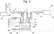
Fig. 3] Fig. 3 is a schematic configuration diagram illustrating another modification of a gas analyzer according to the present invention. - Embodiments of a gas analyzer according to the present invention will be described with reference to
Figs. 1 to 3 . - A
gas analyzer 10 of the present embodiment is used to measure the concentration of a predetermined substance (for example, nitrogen oxides, sulfur oxides, carbon monoxide, carbon dioxide, and oxygen) contained in an exhaust gas collected by agas collection probe 91 attached to a gas discharge unit of an exhaustgas generation facility 90, such as a thermal power plant, a waste incineration plant, and a factory, and introduced through apipeline 92. - The
gas analyzer 10 includes agas intake port 11 and agas analysis unit 12, which are connected by an analysis targetgas flow path 13. For thegas analysis unit 12, for example, a non-dispersive infrared (NDIR) spectrometer is used. In addition, an analysistarget gas pump 15 is connected to the analysis targetgas flow path 13. - When the analysis target gas containing water vapor is introduced into the analyzer after calibration of the analyzer, an amount of water vapor in the analyzer is different between the time of calibration and the time of measurement, and the reliability of the measurement result is lowered. Therefore, the
gas analyzer 10 includes a cooling unit (cooler) 14 in the middle of the analysis targetgas flow path 13 from thegas intake port 11 to thegas analysis unit 12. The analysis target gas is cooled to a predetermined temperature by thecooling unit 14 and then introduced into thegas analysis unit 12. Although onecooling unit 14 is provided in the present embodiment, an analysis target gas may be cooled in stages by arranging a plurality of cooling units. - In the
cooling unit 14, adrain flow path 141 is connected to the analysis targetgas flow path 13. Thedrain flow path 141 extends vertically downward. Liquid (drain) such as water generated by cooling of an analysis target gas in thecooling unit 14 is discharged to a closedcontainer 20 described later through thedrain flow path 141. - In addition, the
gas analyzer 10 includes adrain separator 16 closer to thegas intake port 11 than thecooling unit 14 of the analysis targetgas flow path 13 is. Thedrain separator 16 separates and collects drain generated in the analysis targetgas flow path 13 at a preceding stage of thecooling unit 14 from the exhaust gas. Thedrain separator 16 is also provided with adrain flow path 161 extending vertically downward and reaching the closedcontainer 20. - The closed
container 20 is a closed drain pot and stores drain introduced from thecooling unit 14 and thedrain separator 16 through thedrain flow paths lid 201 is provided on an upper surface of the closedcontainer 20, and the closedcontainer 20 is closed by thelid 201 during use of thegas analyzer 10. At the time of maintenance of thegas analyzer 10, thelid 201 is removed, and removal of liquid remaining in theclosed container 20 and cleaning of the inside of theclosed container 20 can be performed as described later. - A
tube 21 is accommodated in theclosed container 20. Both ends of thetube 21 extend to the outside of theclosed container 20. A part of thetube 21 disposed in theclosed container 20 is aselective permeation member 211. Theselective permeation member 211 is a tube which selectively let gas-phase water permeate, and for example, those described inPatent Literature 2 andNon Patent Literature 1 are used as theselective permeation member 211. The tubes described in these documents are made of a fluorine-based cation exchange resin having a cation exchange group, and have a characteristic in which only water can selectively permeate (nitric acid or sulfuric acid does not permeate) to a side with a lower partial pressure of water vapor between the inside and the outside of the tube. A portion of thetube 21 on both end sides of theselective permeation member 211 is made of rubber, plastic, or the like different from the material of theselective permeation member 211. - An exhaust port of a pump 22 (different from the analysis target gas pump 15) is connected to one end (first end 23) of the
tube 21. One end of anintake pipe 24 is connected to the intake port side of the pump 22, and the other end of theintake pipe 24 is agas introduction port 25 opened to the atmosphere. The pump 22 is a gas source which introduces an atmospheric air, which is a gas different from the analysis target gas, from one end of thetube 21 into theselective permeation member 211 in thetube 21. As described above, the inside of theselective permeation member 211 into which a gas is introduced from a gas source corresponds to agas introduction space 210, and a space in theclosed container 20 other than thetube 21 corresponds to adrain introduction space 200. - The other end (second end) of the
tube 21 is agas discharge port 26 opened to the atmosphere. - The operation of the
gas analyzer 10 of the present embodiment will be described. In a state where the exhaustgas generation facility 90 is in operation, thegas intake port 11 is opened and the analysistarget gas pump 15 is operated under the control of a control unit (not illustrated). As a result, the analysis target gas collected by thegas collection probe 91 is taken in from thegas intake port 11 through thepipeline 92, introduced into thegas analysis unit 12 through the analysis targetgas flow path 13, and analyzed. - During the analysis, the analysis target gas is cooled by the cooling
unit 14 provided in the middle of the analysis targetgas flow path 13, and thus drain is generated. The drain is discharged to thedrain introduction space 200 in theclosed container 20 through thedrain flow path 141. In addition, the drain separated from the analysis target gas by thedrain separator 16 is also discharged to thedrain introduction space 200 through thedrain flow path 161. The drain contains water derived from water vapor contained in the exhaust gas having been liquefied and the components of nitric acid and sulfuric acid obtained by dissolving, in that water, nitrogen oxides and sulfur oxides having been contained in the exhaust gas. - During the analysis, the atmospheric air is continuously supplied from the
gas introduction port 25 to thetube 21 by operating the pump (gas source) 22. When a storage amount of the drain discharged into theclosed container 20 increases, theselective permeation member 211 disposed in theclosed container 20 comes into contact with the drain. Then, since the water vapor partial pressure inside theselective permeation member 211 which is a part of thetube 21, that is, thegas introduction space 210 becomes lower than the water vapor partial pressure outside theselective permeation member 211, that is, thedrain introduction space 200, the water contained in the drain selectively permeates from the outside to the inside of theselective permeation member 211, that is, from thedrain introduction space 200 toward the gas introduction space 210 (components of nitric acid and sulfuric acid do not permeate). - The water that thus permeated through the
gas introduction space 210 is taken into the atmospheric air passing through thetube 21 and discharged from thegas discharge port 26. Since the gas discharged from thegas discharge port 26 contains only the atmospheric air taken in from thegas introduction port 25 and water selectively collected from the drain, the gas can be released into the environment without any treatment. - By continuously supplying the atmospheric air from the pump 22 to the
tube 21 in this manner, water is discharged from theclosed container 20. Although liquid other than water, such as nitric acid and sulfuric acid, remains in theclosed container 20, the amount of remaining liquid can be suppressed because water is discharged in this manner. As a result, a frequency of collection of the liquid in theclosed container 20 can be reduced as compared with a case where the drain is collected in a state where the water is still contained, and thus the trouble can be reduced. Although a collection frequency depends on a capacity of theclosed container 20, if, for example, a capacity for one cycle or more of a periodic inspection of the exhaustgas generation facility 90 is secured, it is not necessary to pay attention to an amount of drain in theclosed container 20 except for the time of maintenance, so that the management can be remarkably simplified. - The present invention is not limited to the above embodiment, and various variations are possible. For example, in the above embodiment, the pump 22 is used as the gas source, but instead, as in a
gas analyzer 30 illustrated inFig. 2 , agas cylinder 32 may be used as the gas source. As a gas supplied from thegas cylinder 32, for example, dry air can be used. Alternatively, an inert gas such as nitrogen gas or argon gas may be used, or a gas other than the inert gas may be used. By introducing a dry gas such as dry air from thegas cylinder 32 into thetube 21, a partial pressure of water in thetube 21 can be lowered, so that the discharge of water vapor from theclosed container 20 into thetube 21 can be prompted. - In addition, instead of the pump 22, a combination of a compressor and a filter regulator may be used. The filter regulator functions as a filter that removes dust or the like contained in the atmospheric air supplied from the compressor, and has a function of adjusting a pressure of the atmospheric air supplied to the
tube 21. - Alternatively, instead of using the pump 22, the gas discharged from the
gas analysis unit 12 may be introduced from thegas introduction port 25. - In the above embodiment, the
drain separator 16 is provided in the analysis targetgas flow path 13 in addition to thecooling unit 14, but, as in thegas analyzer 30 illustrated inFig. 2 , thedrain separator 16 may be omitted. Note that althoughFig. 2 illustrates an example in which thegas cylinder 32 is provided and thedrain separator 16 is omitted, the pump 22 may be provided instead of thegas cylinder 32 to omit thedrain separator 16, or thegas cylinder 32 and thedrain separator 16 may be provided. - In addition, as in a
gas analyzer 40 illustrated inFig. 3 , the inside of theclosed container 20 may be partitioned into two spaces by a membrane (selective permeation member) 42 made of a material that selectively lets gas-phase water permeate, the drain flow path 141 (thedrain flow path 161 in a case where thedrain separator 16 is provided) may be connected to adrain introduction space 202 which is one space, and a gas flow path 41 from the gas source (the pump 22 inFig. 3 ) may be connected to agas introduction space 203 which is the other space. Agas discharge path 410 leading to thegas discharge port 26 is further connected to thegas introduction space 203. Also in this example, thegas cylinder 32 or the combination of the compressor and the filter regulator may be provided instead of the pump 22, or a gas discharged from thegas analysis unit 12 may be introduced into thegas introduction space 203. In addition, in this example, thedrain separator 16 may be omitted. - With this configuration, by supplying a gas from the gas source (pump 22) to the
gas introduction space 203 through the gas flow path 41 in a state where drain supplied from the drain flow paths 141 (and 161) is stored in thedrain introduction space 202, only water in the drain selectively permeates themembrane 42 and enters thegas introduction space 203. The water that has entered thegas introduction space 203 is taken into the gas, and then discharged to the outside from thegas discharge port 26 via thegas discharge path 410. - It will be understood by those skilled in the art that the exemplary embodiments described above are specific examples of the following aspects.
- A gas analyzer according to
clause 1 includes: - an analysis target gas flow path through which an analysis target gas flows;
- a cooling unit which is provided in the analysis target gas flow path and configured to cool the analysis target gas;
- a drain flow path through which liquid generated in the cooling unit is discharged;
- a closed container connected to the drain flow path;
- a selective permeation member which is a member partitioning the inside of the closed container into a drain introduction space connected to the drain flow path and a gas introduction space and configured to selectively let gas-phase water permeate from the drain introduction space to the gas introduction space;
- a gas source configured to introduce a gas into the gas introduction space; and
- a gas discharge port through which the gas in the gas introduction space is discharged.
- With the gas analyzer according to
clause 1, the inside of the closed container (closed drain pot) is divided into the drain introduction space connected to the drain flow path and the gas introduction space into which a gas is introduced by the gas source by the selective permeation member configured to selectively let gas-phase water permeate. When a gas (different from an analysis target gas) is introduced into the gas introduction space by a gas source, only water out of water containing nitric acid or sulfuric acid generated in a cooling unit and introduced into the drain introduction space of the closed container from a drain flow path permeates through the selective permeation member and enters the gas introduction space. The water that has entered the gas introduction space is taken into the gas and discharged to the outside from a gas discharge port. At that time, since the gas neither contains nitric acid nor sulfuric acid, there is no problem even if the gas is released into the environment without any treatment. Water is discharged from the closed container in this manner, and nitric acid and sulfuric acid are concentrated and stored in the drain introduction space of the closed container. Note that nitric acid and sulfuric acid in the drain introduction space need to be collected periodically (for example, when a facility is stopped for maintenance), but since a frequency of collection can be reduced as compared with a case where nitric acid and sulfuric acid are collected in a state of being contained in water as in the conventional case, it is possible to reduce labor. As described above, with the present invention, it is possible to easily treat water generated from an analysis target gas and collected in the closed container (closed drain pot). - A gas analyzer according to
clause 2 is a gas analyzer according toclause 1, further including a tube having a first end and a second end disposed outside the closed container, wherein - the selective permeation member is provided between the first end and the second end of the tube, and
- the gas source is connected to the first end of the tube.
- With the gas analyzer according to
clause 2, the selective permeation member can be easily configured using a commercially available tube, such as a tube made of a fluorine-based cation exchange resin having a cation exchange group described inPatent Literature 2 orNon Patent Literature 1. - A gas analyzer according to clause 3 is the gas analyzer according to
clause - With the gas analyzer according to clause 3, since the atmospheric air is used as the gas, it is not necessary to manage a remaining amount of the gas and the like as in a case of using a gas cylinder, and the management is facilitated.
- A gas analyzer according to clause 4 is the gas analyzer according to
clause - With the gas analyzer according to clause 4, the partial pressure of water in the tube is lowered by using the dry gas (for example, an air having a water vapor content lower than that of the atmospheric air, a nitrogen gas, or the like) as the gas, and the discharge of the water vapor from the closed container into the tube can be promoted.
- A gas analyzer according to clause 5 is the gas analyzer according to any one of
clauses 1 to 4, further including an analysis unit provided on a downstream side of the analysis target gas flow path and configured to analyze the analysis target gas, wherein
the cooling unit is provided on an upstream side of the analysis unit in the analysis target gas flow path. - With the gas analyzer according to clause 5, the analysis unit can be protected from heat by providing the cooling unit on the upstream side of the analysis unit.
- A drain treatment method according to clause 6 is a method for treating liquid generated by cooling an analysis target gas in a gas analyzer, the method including:
- a collecting step of collecting the liquid in a closed container;
- a water separation step of separating water from the liquid in the closed container without separating nitric acid and sulfuric acid; and
- a water discharging step of discharging the water to the outside of the closed container.
- A drain treatment method according to clause 7 is the drain treatment method according to clause 6, wherein, in the water separation step, water is separated from the liquid by a selective permeation member made of a material that selectively lets gas-phase water permeate.
- A drain treatment method according to clause 8 is the drain treatment method according to clause 7, wherein, in the water separation step, a gas is introduced into a tube having the selective permeation member.
- With the drain treatment methods according to clauses 6 to 8, water generated from the analysis target gas and collected in the closed container can be easily treated.
-
- 10, 30, 40... Gas Analyzer
- 11... Gas Intake Port
- 12... Gas Analysis Unit
- 13... Analysis Target Gas Flow Path
- 14... Cooling Unit
- 141, 161... Drain Flow Path
- 15... Analysis Target Gas Pump
- 16... Drain Separator
- 20... Closed Container
- 200... Drain Introduction Space
- 201... Lid
- 202... Storage Space
- 203... Gas Introduction Space
- 21... Tube
- 210... Gas Introduction Space
- 211... Selective Permeation Member
- 22... Pump
- 23... First End
- 24... Intake Pipe
- 25... Gas Introduction Port
- 26... Gas Discharge Port (Second End)
- 32... Gas Cylinder
- 41... Gas Flow Path
- 410... Gas Discharge Path
- 42... Membrane (Selective Permeation Member)
- 90... Exhaust Gas Generation Facility
- 91... Gas Collection Probe
- 92... Pipeline
Claims (8)
- A gas analyzer comprising:an analysis target gas flow path through which an analysis target gas flows;a cooling unit which is provided in the analysis target gas flow path and configured to cool the analysis target gas;a drain flow path through which liquid generated in the cooling unit is discharged;a closed container connected to the drain flow path;a selective permeation member which is a member partitioning an inside of the closed container into a drain introduction space connected to the drain flow path and a gas introduction space and configured to selectively let gas-phase water permeate from the drain introduction space to the gas introduction space;a gas source configured to introduce a gas into the gas introduction space; anda gas discharge port through which the gas in the gas introduction space is discharged.
- The gas analyzer according to claim 1, further comprising a tube having a first end and a second end disposed outside the closed container, whereinthe selective permeation member is provided between the first end and the second end of the tube, andthe gas source is connected to the first end of the tube.
- The gas analyzer according to claim 1, wherein the gas source is a gas cylinder configured to store a dry gas.
- The gas analyzer according to claim 1, wherein the gas source is a pump configured to supply an atmospheric air to the gas introduction space.
- The gas analyzer according to claim 1, further comprising an analysis unit provided on a downstream side of the analysis target gas flow path and configured to analyze the analysis target gas, wherein
the cooling unit is provided on an upstream side of the analysis unit in the analysis target gas flow path. - A drain treatment method for treating liquid generated by cooling an analysis target gas in a gas analyzer, the method comprising:a collecting step of collecting the liquid in a closed container;a water separation step of separating water from the liquid in the closed container without separating nitric acid and sulfuric acid; anda water discharging step of discharging the water to an outside of the closed container.
- The drain treatment method according to claim 6, wherein, in the water separation step, water is separated from the liquid by a selective permeation member made of a material that selectively lets gas-phase water permeate.
- The drain treatment method according to claim 7, wherein, in the water separation step, a gas is introduced into a tube having the selective permeation member.
Applications Claiming Priority (2)
| Application Number | Priority Date | Filing Date | Title |
|---|---|---|---|
| JP2021034137 | 2021-03-04 | ||
| PCT/JP2021/039007 WO2022185604A1 (en) | 2021-03-04 | 2021-10-21 | Gas analysis device |
Publications (2)
| Publication Number | Publication Date |
|---|---|
| EP4303557A1 true EP4303557A1 (en) | 2024-01-10 |
| EP4303557A4 EP4303557A4 (en) | 2024-08-14 |
Family
ID=83154221
Family Applications (1)
| Application Number | Title | Priority Date | Filing Date |
|---|---|---|---|
| EP21929165.5A Pending EP4303557A4 (en) | 2021-03-04 | 2021-10-21 | GAS ANALYSIS DEVICE |
Country Status (5)
| Country | Link |
|---|---|
| US (1) | US20240183761A1 (en) |
| EP (1) | EP4303557A4 (en) |
| JP (1) | JP7521684B2 (en) |
| CN (1) | CN116997786A (en) |
| WO (1) | WO2022185604A1 (en) |
Family Cites Families (16)
| Publication number | Priority date | Publication date | Assignee | Title |
|---|---|---|---|---|
| JPS59183367A (en) * | 1983-04-04 | 1984-10-18 | Ishikawa Seisakusho:Kk | Volatile component concentration measuring device |
| JP2893797B2 (en) * | 1990-02-19 | 1999-05-24 | 株式会社島津製作所 | Humidifier |
| JPH0650950A (en) * | 1992-07-29 | 1994-02-25 | Nec Corp | Specimen concentration-trap device |
| JP3268298B2 (en) * | 1997-07-07 | 2002-03-25 | 株式会社カマタテクナス | High pressure air dehumidifier |
| JP3984364B2 (en) * | 1998-05-22 | 2007-10-03 | 株式会社堀場製作所 | Gas analyzer sampling device |
| JP2000206013A (en) | 1999-01-07 | 2000-07-28 | Horiba Ltd | Dehumidifier for gas analyzer |
| JP2003075307A (en) | 2001-08-31 | 2003-03-12 | Nikkiso Co Ltd | Sampling system for exhaust gas sampling gas containing radioactive substances |
| JP4193692B2 (en) | 2003-12-26 | 2008-12-10 | 株式会社島津製作所 | Sample analyzer for gas analyzer |
| JP4573746B2 (en) | 2005-10-17 | 2010-11-04 | 三菱電機株式会社 | Tritium monitor |
| JP4832392B2 (en) * | 2007-09-20 | 2011-12-07 | Agcエンジニアリング株式会社 | Coagulated water remover |
| JP5630099B2 (en) | 2010-06-29 | 2014-11-26 | 三洋電機株式会社 | Drain water neutralizer |
| JP2017213477A (en) | 2014-10-14 | 2017-12-07 | Agcエンジニアリング株式会社 | Water vapor selection permeable tube |
| JP2016156689A (en) | 2015-02-24 | 2016-09-01 | 三菱重工業株式会社 | Gas analysis system, gas calorific power monitoring system, gas plant, and gas analysis method |
| AU2018355018B2 (en) | 2017-10-25 | 2024-02-08 | Memsift Innovations Pte. Ltd. | Membrane water treatment system and method thereof |
| CN209264548U (en) * | 2018-12-10 | 2019-08-16 | 青岛国瑞力恒环保科技有限公司 | A kind of preprocessing unit of optics flue gas analyzer |
| JP7151650B2 (en) * | 2019-07-11 | 2022-10-12 | 株式会社島津製作所 | gas analyzer |
-
2021
- 2021-10-21 EP EP21929165.5A patent/EP4303557A4/en active Pending
- 2021-10-21 CN CN202180095090.5A patent/CN116997786A/en active Pending
- 2021-10-21 JP JP2023503369A patent/JP7521684B2/en active Active
- 2021-10-21 US US18/279,295 patent/US20240183761A1/en active Pending
- 2021-10-21 WO PCT/JP2021/039007 patent/WO2022185604A1/en not_active Ceased
Also Published As
| Publication number | Publication date |
|---|---|
| JP7521684B2 (en) | 2024-07-24 |
| US20240183761A1 (en) | 2024-06-06 |
| CN116997786A (en) | 2023-11-03 |
| JPWO2022185604A1 (en) | 2022-09-09 |
| WO2022185604A1 (en) | 2022-09-09 |
| EP4303557A4 (en) | 2024-08-14 |
Similar Documents
| Publication | Publication Date | Title |
|---|---|---|
| KR102223988B1 (en) | Low Pressure Biogas Sample Takeoff and Conditioning System | |
| US20020019058A1 (en) | Device to alternately supply a fluid to an analyzer | |
| EP2418470A1 (en) | Measurement device, measurement method, and carbon dioxide recovery system | |
| CN110869731B (en) | Device for treating a liquid to be analyzed | |
| EP4303557A1 (en) | Gas analysis device | |
| CN119715870A (en) | Device and method for monitoring ozone layer depletion substances and hydrofluorocarbon in atmosphere | |
| CN109588052B (en) | System and apparatus for evaluating the performance of carbon dioxide separation membrane modules | |
| CN212348021U (en) | Pretreatment device for kiln tail gas | |
| US4272481A (en) | System and method for providing a vapor phase sample for analysis | |
| JP5123833B2 (en) | Gas collector, gas sampling system, exhaust gas separation method and exhaust gas analysis method | |
| CN208366946U (en) | The device that gas is analyzed in a kind of pair of high-sulfur atmosphere | |
| US9714888B2 (en) | Apparatus for fast high pressure syngas sampling | |
| CN101046481B (en) | Sample treating device, and measuring instrument provided therewith | |
| JPH09329533A (en) | Metal sampling method for unhydrolyzable gas, and system therefor | |
| KR102397855B1 (en) | Cooling system for sample collection of reactor | |
| US8875559B2 (en) | System and method for measuring the concentration of impurities mixed with hydrogen gas | |
| CN213364369U (en) | Purification, transmission and sampling device for volatile organic compounds in waste gas of fixed pollution source | |
| JP4804297B2 (en) | Gas sampling apparatus and gas sampling method | |
| US12416447B2 (en) | Carbon dioxide reusing system and method | |
| CN208255166U (en) | Gas-detecting device | |
| CN108872480A (en) | The device that gas is analyzed in a kind of pair of high-sulfur atmosphere | |
| JP2000009611A (en) | Sampling gas analyzer | |
| CN116223603A (en) | Electrochemical Differential Mass Spectrometry Test System Applied to Electrolyte System | |
| CN222439375U (en) | Transformer oil spectral analysis degassing measurement device based on double gas chamber headspace degassing | |
| CN116659945A (en) | Amine liquid sampling device for carbon dioxide capture and carbon dioxide capture system |
Legal Events
| Date | Code | Title | Description |
|---|---|---|---|
| STAA | Information on the status of an ep patent application or granted ep patent |
Free format text: STATUS: THE INTERNATIONAL PUBLICATION HAS BEEN MADE |
|
| PUAI | Public reference made under article 153(3) epc to a published international application that has entered the european phase |
Free format text: ORIGINAL CODE: 0009012 |
|
| STAA | Information on the status of an ep patent application or granted ep patent |
Free format text: STATUS: REQUEST FOR EXAMINATION WAS MADE |
|
| 17P | Request for examination filed |
Effective date: 20230929 |
|
| AK | Designated contracting states |
Kind code of ref document: A1 Designated state(s): AL AT BE BG CH CY CZ DE DK EE ES FI FR GB GR HR HU IE IS IT LI LT LU LV MC MK MT NL NO PL PT RO RS SE SI SK SM TR |
|
| DAV | Request for validation of the european patent (deleted) | ||
| DAX | Request for extension of the european patent (deleted) | ||
| A4 | Supplementary search report drawn up and despatched |
Effective date: 20240712 |
|
| RIC1 | Information provided on ipc code assigned before grant |
Ipc: G01N 1/22 20060101AFI20240708BHEP |
|
| GRAP | Despatch of communication of intention to grant a patent |
Free format text: ORIGINAL CODE: EPIDOSNIGR1 |
|
| STAA | Information on the status of an ep patent application or granted ep patent |
Free format text: STATUS: GRANT OF PATENT IS INTENDED |
|
| INTG | Intention to grant announced |
Effective date: 20251002 |