EP4303444A1 - Kreiselpumpe mit einem gehäuse - Google Patents
Kreiselpumpe mit einem gehäuse Download PDFInfo
- Publication number
- EP4303444A1 EP4303444A1 EP23183565.3A EP23183565A EP4303444A1 EP 4303444 A1 EP4303444 A1 EP 4303444A1 EP 23183565 A EP23183565 A EP 23183565A EP 4303444 A1 EP4303444 A1 EP 4303444A1
- Authority
- EP
- European Patent Office
- Prior art keywords
- coil
- housing
- circuit board
- centrifugal pump
- spacing device
- Prior art date
- Legal status (The legal status is an assumption and is not a legal conclusion. Google has not performed a legal analysis and makes no representation as to the accuracy of the status listed.)
- Granted
Links
Images

Classifications
-
- F—MECHANICAL ENGINEERING; LIGHTING; HEATING; WEAPONS; BLASTING
- F04—POSITIVE - DISPLACEMENT MACHINES FOR LIQUIDS; PUMPS FOR LIQUIDS OR ELASTIC FLUIDS
- F04D—NON-POSITIVE-DISPLACEMENT PUMPS
- F04D13/00—Pumping installations or systems
- F04D13/02—Units comprising pumps and their driving means
- F04D13/06—Units comprising pumps and their driving means the pump being electrically driven
- F04D13/0686—Mechanical details of the pump control unit
-
- F—MECHANICAL ENGINEERING; LIGHTING; HEATING; WEAPONS; BLASTING
- F04—POSITIVE - DISPLACEMENT MACHINES FOR LIQUIDS; PUMPS FOR LIQUIDS OR ELASTIC FLUIDS
- F04D—NON-POSITIVE-DISPLACEMENT PUMPS
- F04D29/00—Details, component parts, or accessories
- F04D29/40—Casings; Connections of working fluid
- F04D29/42—Casings; Connections of working fluid for radial or helico-centrifugal pumps
- F04D29/426—Casings; Connections of working fluid for radial or helico-centrifugal pumps especially adapted for liquid pumps
-
- F—MECHANICAL ENGINEERING; LIGHTING; HEATING; WEAPONS; BLASTING
- F04—POSITIVE - DISPLACEMENT MACHINES FOR LIQUIDS; PUMPS FOR LIQUIDS OR ELASTIC FLUIDS
- F04D—NON-POSITIVE-DISPLACEMENT PUMPS
- F04D29/00—Details, component parts, or accessories
- F04D29/58—Cooling; Heating; Diminishing heat transfer
- F04D29/5813—Cooling the control unit
-
- H—ELECTRICITY
- H02—GENERATION; CONVERSION OR DISTRIBUTION OF ELECTRIC POWER
- H02K—DYNAMO-ELECTRIC MACHINES
- H02K11/00—Structural association of dynamo-electric machines with electric components or with devices for shielding, monitoring or protection
- H02K11/0094—Structural association with other electrical or electronic devices
-
- H—ELECTRICITY
- H02—GENERATION; CONVERSION OR DISTRIBUTION OF ELECTRIC POWER
- H02K—DYNAMO-ELECTRIC MACHINES
- H02K11/00—Structural association of dynamo-electric machines with electric components or with devices for shielding, monitoring or protection
- H02K11/30—Structural association with control circuits or drive circuits
- H02K11/33—Drive circuits, e.g. power electronics
-
- F—MECHANICAL ENGINEERING; LIGHTING; HEATING; WEAPONS; BLASTING
- F05—INDEXING SCHEMES RELATING TO ENGINES OR PUMPS IN VARIOUS SUBCLASSES OF CLASSES F01-F04
- F05D—INDEXING SCHEME FOR ASPECTS RELATING TO NON-POSITIVE-DISPLACEMENT MACHINES OR ENGINES, GAS-TURBINES OR JET-PROPULSION PLANTS
- F05D2260/00—Function
- F05D2260/20—Heat transfer, e.g. cooling
- F05D2260/221—Improvement of heat transfer
- F05D2260/2214—Improvement of heat transfer by increasing the heat transfer surface
- F05D2260/22141—Improvement of heat transfer by increasing the heat transfer surface using fins or ribs
-
- H—ELECTRICITY
- H02—GENERATION; CONVERSION OR DISTRIBUTION OF ELECTRIC POWER
- H02K—DYNAMO-ELECTRIC MACHINES
- H02K2211/00—Specific aspects not provided for in the other groups of this subclass relating to measuring or protective devices or electric components
- H02K2211/03—Machines characterised by circuit boards, e.g. pcb
Definitions
- the invention relates to a centrifugal pump having a motor for conveying a fluid and a housing having a circuit board.
- the invention further relates to a method for arranging an electronic component in a housing of a centrifugal pump having a motor for conveying a fluid.
- the invention further relates to a corresponding use.
- Centrifugal pumps are known from the prior art and are used to convey a fluid by means of a rotary movement of an impeller.
- the fluid to be pumped enters a pump chamber of the centrifugal pump via a suction opening, is captured by the rotating impeller and is subsequently transported into a line section, which is also referred to as a pressure pipe.
- centrifugal pumps often have a housing, which can be designed in two parts as a motor housing and an electronics housing.
- a motor for driving the impeller is provided in the motor housing and a circuit board with electronic components is provided in the electronics housing, which often form a frequency converter for controlling the motor.
- the electronic components regularly include capacitors and coils, which, depending on the pump performance of the centrifugal pump, are much larger in terms of the space required in the electronics housing than, for example, resistors, microprocessors and transistors required to control the centrifugal pump.
- a centrifugal pump having a motor for conveying a fluid and a housing, wherein in the housing a circuit board, a coil electronically conductively connected to the circuit board, having a bottom and a top side, and a spacing device arranged on the circuit board are provided is, the underside of the coil is arranged on the spacing device and the coil is spaced apart from the circuit board, and the top of the coil is thermally connected to the housing on the inside.
- the coil is arranged at a distance from the circuit board, a higher packing density of electronic components on the circuit board can be achieved, since further electronic components can be arranged on the circuit board under the coil.
- the dimensions of the circuit board and thus the housing of the centrifugal pump can be reduced, which leads to a more compact design of the centrifugal pump and lower manufacturing costs for the centrifugal pump.
- the thermal connection to the housing allows for better heat transfer for improved cooling of the coil on the other hand, an improved fixation of the coil in the housing, so that the coil becomes less sensitive to vibrations that regularly occur in centrifugal pumps.
- the centrifugal pump is generally suitable for pumping any fluid. Due to its robustness against solids and chemicals, the centrifugal pump is particularly suitable for use as a dirty water and/or wastewater submersible pump. Dirty water and/or wastewater submersible pumps are used in particular for pumping out dirty water, for example from floodwaters, in flooded construction pits, in laundry rooms, in muddy pits, in biotopes and/or from garden ponds, from seepage shafts and in cellars, and in particular for pumping water with different degrees of contamination such as stones, mud, debris or feces.
- centrifugal pump can also be used for heating with radiators, radiator heating, underfloor heating, ceiling cooling, water circulation in a drinking water system or a drinking water system with a storage charging system, although the above list is not exhaustive, but includes other types of systems not mentioned here can.
- the motor is preferably arranged within the housing, which housing is preferably designed to be moisture-tight.
- the motor regularly drives an impeller connected to the motor via a motor shaft to convey the fluid.
- the housing preferably has a cylindrical shape, with the impeller being provided on one end face and the circuit board opposite thereto on the other end face, so that the motor is arranged between the impeller and the circuit board.
- the printed circuit board is preferably made of an electrically insulating material such as fiber-reinforced plastic with conductive connections adhering to it as conductor tracks. Even if the circuit board can in principle extend axially, it is preferably provided that the circuit board extends radially with respect to the cylindrical housing, which enables a compact design of the centrifugal pump. Accordingly, it is particularly preferred if the circuit board has a circular shape, although other shapes are also conceivable.
- the coil is preferably soldered to the conductor tracks of the circuit board. Further preferably, connections of the coil, in particular wire connections, are guided down from the spaced position of the coil onto the circuit board.
- the connections typically two or four connections, can be guided, for example, through holes in a surface of the spacing device or can be guided onto the circuit board on the outside of the spacing device.
- the coil preferably rests with its underside touching the spacing device.
- a plurality of coils can be provided on the spacing device, for example 2, 3 or 4 coils, which are provided next to one another on the spacing device.
- Arranged on the spacer device means in particular that the coil is arranged oriented away from the spacer device with respect to the circuit board.
- the coil preferably has an inductance of 2, 3, 5, 7 or 10 mH.
- the coil is provided on the spacing device, but is oriented towards the circuit board and is also arranged at a distance from the circuit board.
- two coils can be provided on the spacing device, once oriented from the base surface towards the circuit board and once oriented away from the base surface away from the circuit board.
- three levels of electronic components can even be provided. Complained means that the coil, apart from the connections, does not rest on the circuit board, in particular it does not touch the circuit board.
- a coil is understood to mean, in particular, one or more windings that are suitable for generating or detecting a magnetic field, or that act as a filter, in particular an inductive passive component whose essential property is a defined inductance.
- the coil is preferably designed like a cylinder, with the end faces forming the bottom and top. Thermally bonded means that the coil can transfer heat to the housing.
- the centrifugal pump has at least one electronic component which is arranged between the coil and the circuit board.
- the electronic component is preferably arranged below the spacing device and/or connected to the circuit board in an electronically conductive manner.
- the electronic component can comprise a capacitor, in particular a cuboid film capacitor, a further coil, a resistor, a transistor and/or a combination and/or plurality of the aforementioned electronic components.
- the top of the coil is in contact with the housing and/or a thermal paste is provided between the top of the coil and the housing.
- the coil preferably lies against the housing with its entire end face and particularly preferably with part of the lateral surface, the end face of the coil preferably extending parallel to the end face of the housing.
- the thermal paste also called gap filler or gap pad, can be provided between the coil and the housing for better heat transfer.
- the thermal paste can preferably comprise silicone oil, whereby a silicone-free thermal paste made of polyethylene glycol (PEG) with filler zinc oxide, or with aluminum, copper, graphite and silver particles can be provided.
- the housing has cooling fins on the outside in the area of the coil.
- a plurality of cooling fins are preferably provided, which extend over part or the entire end face of the housing.
- the cooling fins increase the size of the outside of the housing in order to improve heat transfer to the environment and thus cooling of the coil.
- the cooling fins can be milled into the housing or produced by casting the housing.
- the spacing device is mechanically connected to the circuit board, in particular by means of locking hooks, and/or the spacing device is soldered to the circuit board.
- the mechanical connection makes the spacing device and the coil provided thereon less sensitive to vibrations of the centrifugal pump, which can occur regularly during operation of the centrifugal pump.
- the spacing device can be glued to the circuit board, screwed or otherwise fixedly connected to the circuit board.
- the spacing device is designed like a table with legs, which legs are attached to the circuit board.
- the legs preferably extend vertically from a base area of the spacing device which accommodates the coil towards the circuit board.
- the base area preferably extends parallel to the circuit board.
- the spacing device preferably has three or four or even more legs, which are provided in particular at corners of the base area.
- the base area can be rectangular or square, although other shapes are also conceivable.
- Connections of the coil are preferably routed along the legs from the circuit board to the coil and more preferably soldered to conductor tracks of the circuit board in order to achieve a stationary fixation of the coil in relation to the circuit board.
- the spacing device can be made of plastic, although other materials such as metal are also conceivable.
- the legs can also be made of plastic, with metal soldering feet being provided at the end of the legs for soldering to the circuit board.
- the housing has a recess on the inside, from which the top of the coil is received, in particular in a form-fitting manner.
- the recesses can be designed as a recess and/or circular, with an inner diameter of such a circular recess corresponding to the outer diameter of the coil.
- the centrifugal pump has at least one capacitor, which is arranged next to the spacing device on the circuit board and in particular rests on the inside of the housing.
- the capacitor can be held stationary by the housing as well as the coil and heat can be transferred from the capacitor to the housing, a recess corresponding to the shape of the capacitor can also be provided on the housing.
- the capacitor can have an extension oriented away from the circuit board, which is the same or substantially the same as the extension of the spacing device, oriented away from the circuit board, together with the coil arranged thereon.
- a plurality of capacitors can be provided on the circuit board.
- the capacitor is preferably designed as a film capacitor, as an electrolytic capacitor and/or having a cylindrical shape.
- the capacitor preferably has a capacity of 0.5, 1, 3 or 5 ⁇ F.
- a frequency converter for the motor comprising the coil is provided on the circuit board.
- the coil, the capacitor and the other electronic components form the frequency converter.
- the frequency converter preferably has a rectifier that feeds a DC intermediate circuit and an inverter fed from this intermediate circuit, whereby an intermediate circuit capacitor, often an electrolytic capacitor, serves to smooth the DC voltage and the capacitor and the coil can serve to suppress interference.
- the inverter preferably has power transistors, for example MOSFETs, IBGTs or IGCTs.
- a control for the motor and/or the frequency converter comprising a microcontroller can also be provided.
- the housing has a motor housing that accommodates the motor and an electronics housing that accommodates the circuit board, and the electronics housing is placed on the motor housing.
- the motor housing and the electronics housing can therefore be designed in two pieces or in one piece.
- the electronics housing is preferably designed like a pot, with the cooling fins being provided on the end face of the pot.
- the motor housing and/or the electronics housing are also preferred has a cylindrical shape, wherein the pot-like electronics housing can be placed with its edge on the motor housing, so that the electronics housing and the motor housing are arranged axially one behind the other.
- Both the electronics housing and the motor housing are preferably made of metal, in particular gray cast iron.
- the electronics housing and the motor housing are preferably screwed together. Cables preferably lead from the circuit board through an end face of the motor housing to the motor.
- the motor housing and/or the electronics housing can each be designed to be moisture-tight.
- the proposed method makes it possible to increase the packing density of electronic components on the circuit board, since in other words the coil is arranged in a second level, so that part of the electronic components can be arranged on the circuit board in the first level.
- the size of the circuit board and the volume of the centrifugal pump can be reduced, resulting in cost savings due to lower material consumption for the housing.
- This makes it possible to provide the circuit board in the housing so that it extends radially.
- the coil is fixed in place not only on the circuit board but also through the housing and is therefore less susceptible to damage caused by vibrations.
- the method has the following step: Potting the circuit board, spacer and coil in the housing.
- the coil, the spacing device and other electronic components provided on the circuit board can be fixed in a stationary manner on the housing, in particular in the electronics housing, so that the aforementioned components are protected against mechanical damage and/or against the ingress of moisture.
- Different casting resins such as epoxy, polyester, polyurethane and silicone can be used for casting.
- the entire pot in which the circuit board with the aforementioned electronic components is provided is preferably cast and can be mounted on the motor housing after the casting resin has hardened.
- the object of the invention is further achieved by using a spacing device, through which spacing device a coil is arranged spaced on a circuit board and electronically connected to it in an electronically conductive manner, the circuit board being provided in a housing of a centrifugal pump having a motor for conveying a fluid
- the underside of the coil is arranged on the spacing device and an upper side of the coil is thermally connected to the housing on the inside.
- Fig. 1 shows a perspective schematic view of a centrifugal pump 1 with a partially opened housing 2 according to a preferred embodiment of the invention
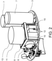
- Fig. 2 shows a perspective schematic view of a circuit board 3 of the centrifugal pump 1 according to the preferred embodiment of the invention.
- the centrifugal pump 1 has a motor 4 arranged in the housing 2 for driving an impeller, not shown, for conveying a fluid.
- the housing 2 is divided into two into a motor housing 5, within which the motor 5 is arranged, and into an electronics housing 6, within which the circuit board 3 is arranged.
- the electronics housing 6 is designed like a pot and its edge is placed in a fixed position on the cylindrical motor housing 5.
- the motor housing 5 is sealed in a particularly moisture-tight manner on its end face facing the electronics housing 6, with cables (not shown) being guided from the circuit board 3 through the end face to the motor 5.
- Both the motor housing 5 and the electronics housing 6 are made of gray cast iron.
- capacitors 7 are electronically conductively connected as electronic components to conductor tracks, not shown, of the printed circuit board 3 and lie with their underside on the printed circuit board 3.
- the capacitors 7 that can be used to smooth an intermediate circuit voltage each have a capacity of > 50 ⁇ F and are designed as cylindrical electrolytic capacitors.
- a table-like spacer 8 made of a plastic material is provided.
- the spacing device 8 has a rectangular, flat base surface 9, the respective corners of which are assigned legs 10 that extend vertically away from the base surface 9.
- the legs 10 are mechanically fastened in a stationary manner to the circuit board 3 by means of locking hooks guided through holes in the circuit board 3, so that the base area 9 extends parallel to the circuit board 3 at a distance of three cm.
- the legs 10 are made of metal and are soldered accordingly to the circuit board 3.
- the base area 9 can be arranged at a distance from the circuit board 3 by, for example, 2, 4, 5 or 7 cm.
- a coil 11 is arranged on the spacing device 8 and correspondingly spaced from the circuit board 3.
- the coil 11 has the shape of a cylinder, the lower end face of which rests touching the base surface 9 as the underside, and has an inductance of 7 mH. Connections of the coil 11 are passed through the base surface 9, guided along the legs 10 and connected in an electronically conductive manner to conductor tracks, not shown, of the circuit board 3.
- three further electronic components 12 are arranged next to one another in an electronically conductive manner with the circuit board 3, which in the present case are also designed as capacitors, but have a lower capacity than the electrolytic capacitors 7, for example have a capacity between 5 nF and ⁇ F, and as Film capacitors are designed with a cuboid shape.
- the further electronic components 12 and the coil 11 are therefore arranged one above the other in two planes or axially one above the other in relation to the housing 2.
- circuit board 3 in addition to the spacing device 8, further electronic components not shown in the figures, such as resistors, transistors or further coils, are provided on the circuit board 3. These electronic components, together with the coil 11, the other electronic components 12 and the capacitors 7, form a frequency converter and/or a controller for the motor 4.
- Fig. 1 is an upper end face as a top 13 of the coil 11 thermally connected to the housing 2 or the electronics housing 6.
- a circular recess 14 is provided on the inside of the electronics housing 6, the inner diameter of which corresponds to the outer diameter of the cylindrical coil 11, so that the coil 11 lies in contact with the electronics housing 6 and its upper side 13 rests in a form-fitting manner. In this way, the coil 11 is fixed in place with respect to vibrations that regularly occur on the centrifugal pump 1 and cannot tear off the circuit board 3.
- a thermally conductive gap filler or a thermal paste can be provided between the top 13 of the coil 11 and the electronics housing 6 in order to realize the thermal connection.
- the thermal paste may include silicone oil, polyethylene glycol (PEG) with zinc oxide or aluminum, copper, graphite and silver particles as a filler.
- a plurality of spaced cooling fins 15 are provided on the outside of the electronics housing 6 and are arranged axially corresponding to the top side 13 of the coil 11.
- the capacitors 7 also touch the inside of the electronics housing 6 with their respective top sides.
- the capacitors 7 are also thermally connected to the electronics housing 6 and, like the coil 11, can emit heat to an area surrounding the centrifugal pump 1 by means of the cooling fins 15.
- the capacitors 7 are also fixed in their position and are therefore arranged insensitive to vibrations of the centrifugal pump 1.
- the spacing device 8 is first arranged on the circuit board 3 in the housing 2 and mechanically connected to the circuit board 3.
- the coil 11 is arranged with its underside on the spacing device 8, so that the coil 11 comes to lie abutting the circuit board 3.
- the coil 11 becomes stationary with respect to the spacing device 8 and the circuit board 3 fixed.
- the top 13 of the coil 11 is thermally connected to the inside of the housing 2.
- the pot-shaped electronics housing 6, in which the circuit board 3 with the coil 11 and the spacing device 8, the capacitors 7 and the other electronic components 12, can be cast with a resin.
- a vibration-stable arrangement, in particular of the coil 11 in the electronics housing 6, as well as a higher packing density on the circuit board 3 can be achieved.
- the spacing device 8 aims to arrange the coil 11 at a distance from the circuit board 3 and to connect it electronically in a conductive manner, the circuit board 3 being provided in the housing 2 of the centrifugal pump 1 having the motor 4 for conveying a fluid, an underside the coil 11 is arranged on the spacing device 8 and the top 13 of the coil 11 is thermally connected to the housing 2.
- centrifugal pump 1 Housing 2 Circuit board 3 engine 4 Motor housing 5 Electronics housing 6 capacitor 7 Distance facility 8th Floor space 9 leg 10 Kitchen sink 11 Electronic component 12 Top 13 recess 14 cooling fin 15
Landscapes
- Engineering & Computer Science (AREA)
- Mechanical Engineering (AREA)
- General Engineering & Computer Science (AREA)
- Power Engineering (AREA)
- Physics & Mathematics (AREA)
- Thermal Sciences (AREA)
- Microelectronics & Electronic Packaging (AREA)
- Structures Of Non-Positive Displacement Pumps (AREA)
Abstract
Description
- Die Erfindung betrifft eine Kreiselpumpe aufweisend einen Motor zum Fördern eines Fluids und ein Gehäuse aufweisend eine Leiterplatte. Die Erfindung betrifft ferner ein Verfahren zum Anordnen eines elektronischen Bauelements in einem Gehäuse einer Kreiselpumpe aufweisend einen Motor zum Fördern eines Fluids. Die Erfindung betrifft weiterhin eine entsprechende Verwendung.
- Kreiselpumpen sind aus dem Stand der Technik bekannt und dienen zum Fördern eines Fluids mittels einer Drehbewegung eines Laufrades. Das zu fördernde Fluid tritt über eine Saugöffnung in einen Pumpenraum der Kreiselpumpe ein, wird von dem rotierenden Laufrad erfasst und in der Folge in einen Leitungsabschnitt, der auch als Druckrohr bezeichnet wird, befördert.
- Derartige Kreiselpumpen weisen oftmals ein Gehäuse auf, welches zweigeteilt als Motorgehäuse und Elektronikgehäuse gestaltet sein kann. In dem Motorgehäuse ist ein Motor zum Antreiben des Laufrads und in dem Elektronikgehäuse ist eine Leiterplatte mit elektronischen Bauelementen vorgesehen, die vielfach einen Frequenzumrichter zum Ansteuern des Motors ausbilden. Die elektronischen Bauelemente umfassen regelmäßig Kondensatoren und Spulen, die in Abhängigkeit von der Pumpenleistung der Kreiselpumpe hinsichtlich ihres in den Elektronikgehäuse benötigten Bauraums wesentlich großvolumigen sind als beispielsweise ebenso für eine Steuerung der Kreiselpumpe benötigte Widerstände, Mikroprozessoren und Transistoren.
- Trotz hoher Packungsdichte derartiger elektronischer Bauelemente wird regelmäßig unverhältnismäßig viel Platz für eine solche Leiterplatte in dem Gehäuse einer Kreiselpumpe benötigt. Infolge davon muss das Gehäuse der Kreiselpumpe unverhältnismäßig groß dimensioniert werden, was zu entsprechenden Mehrkosten bei einer Herstellung und Einschränkungen bei einer Installation der Kreiselpumpe unter beengten Platzverhältnissen führt.
- Ausgehend von dieser Situation ist es eine Aufgabe der vorliegenden Erfindung, eine Kreiselpumpe, und ein entsprechendes Verfahren sowie eine entsprechende Verwendung, anzugeben, die in ihren Abmessungen kompakter und daher kostengünstiger herzustellen ist.
- Die Aufgabe der Erfindung wird durch die Merkmale der unabhängigen Ansprüche gelöst. Vorteilhafte Ausgestaltungen sind in den Unteransprüchen angegeben.
- Demnach wird die Aufgabe gelöst durch eine Kreiselpumpe aufweisend einem Motor zum Fördern eines Fluids und ein Gehäuse, wobei in dem Gehäuse eine Leiterplatte, eine mit der Leiterplatte elektronisch leitend verbundene Spule, aufweisend eine Unterseite und eine Oberseite, und eine auf der Leiterplatte angeordnete Abstandseinrichtung vorgesehen ist, die Unterseite der Spule auf der Abstandseinrichtung und die Spule derart beabstandet zu der Leiterplatte angeordnet ist, und die Oberseite der Spule innenseitig thermisch an das Gehäuse angebunden ist.
- Dadurch, dass die Spule beabstandet zu der Leiterplatte angeordnet ist, lässt sich eine höhere Packungsdichte an elektronischen Bauelementen auf der Leiterplatte erzielen, da unter der Spule weitere elektronische Bauelemente auf der Leiterplatte angeordnet werden können. Gegenüber aus dem Stand der Technik bekannten Ausgestaltungen kann derart die Abmessung der Leiterplatte und damit des Gehäuses der Kreiselpumpe verkleinert werden, was zu einem kompakteren Design der Kreiselpumpe und geringeren Herstellungskosten für die Kreiselpumpe führt. Zudem erlaubt die thermische Anbindung an das Gehäuse einerseits eine bessere Wärmeübertragung zwecks verbesserter Kühlung der Spule sowie andererseits eine verbesserte Fixierung der Spule in dem Gehäuse, sodass die Spule unempfindlicher gegenüber regelmäßig bei Kreiselpumpen auftretenden Schwingungen wird.
- Die Kreiselpumpe eignet sich grundsätzlich zur Förderung jeglichen Fluids. Aufgrund ihrer Robustheit gegenüber Feststoffen und Chemikalien eignet sich die Kreiselpumpe insbesondere zur Verwendung als Schmutzwasser- und/oder Abwasser-Tauchpumpe. Schmutzwasser- und/oder Abwasser-Tauchpumpen dienen insbesondere zum Abpumpen von verdrecktem Wasser beispielsweise von Hochwasser, in überfluteten Baugruben, in Waschküchen, in schlammigen Gruben, in Biotopen und/oder von Gartenteichen, von Sickerschächten sowie in Kellern, und insbesondere zum Pumpen von Wasser mit verschiedenen Verunreinigungsgraden wie beispielsweise Steine, Schlamm Geröll oder Fäkalien. Darüber hinaus kann die Kreiselpumpe auch für eine Heizung mit Heizkörpern, eine Radiatorheizung, eine Fußbodenheizung, eine Deckenkühlung, eine Wasserzirkulation in einer Trinkwasseranlage oder eine Trinkwasseranlage mit Speicherladesystem verwendet werden, wobei vorstehende Aufzählung nicht abschließend ist, sondern weitere, hier nicht genannte Anlagenarten umfasst sein können.
- Der Motor ist bevorzugt innerhalb des Gehäuses angeordnet, welches Gehäuse bevorzugt feuchtigkeitsdicht gestaltet ist. Durch den Motor wird regelmäßig ein über eine Motorwelle an den Motor angebundenes Laufrad zum Fördern des Fluids angetrieben. Das Gehäuse weist bevorzugt eine zylinderartige Form auf, wobei an einer Stirnseite das Laufrad und gegenüberliegend dazu an der anderen Stirnseite die Leiterplatte vorgesehen ist, sodass der Motor zwischen dem Laufrad und der Leiterplatte angeordnet ist. Die Leiterplatte, englisch printed circuit board, ist bevorzugt aus einem elektrisch isolierenden Material wie faserverstärkter Kunststoff mit daran haftenden, leitenden Verbindungen als Leiterbahnen ausgestaltet. Auch wenn sich die Leiterplatte grundsätzlich axial erstrecken kann, ist bevorzugt vorgesehen, dass sich die Leiterplatte radial in Bezug auf das zylinderartige Gehäuse erstreckt, was eine kompakte Bauweise der Kreiselpumpe ermöglicht. Entsprechend ist besonders bevorzugt, wenn die Leiterplatte eine kreisrunde Form aufweist, wobei auch andere Formen denkbar sind.
- Die Spule ist bevorzugt mit den Leiterbahnen der Leiterplatte verlötet. Weiter bevorzugt sind Anschlüsse der Spule, insbesondere Drahtanschlüsse, von der beabstandeten Position der Spule auf die Leiterplatte herunter geführt. Dazu können die Anschlüsse, typischerweise zwei oder vier Anschlüsse, beispielsweise durch Bohrungen einer Oberfläche der Abstandseinrichtung hindurchgeführt sein oder außen an der Abstandseinrichtung auf die Leiterplatte geführt sein. Bevorzugt liegt die Spule mit ihrer Unterseite berührend auf der Abstandseinrichtung auf. Auf der Abstandseinrichtung können eine Mehrzahl Spulen vorgesehen sein, beispielsweise 2, 3 oder 4 Spulen, die nebeneinander auf der Abstandseinrichtung vorgesehen sind. Auf der Abstandseinrichtung angeordnet bedeutet insbesondere, dass die Spule in Bezug auf die Leiterplatte von der Abstandseinrichtung weg orientiert angeordnet ist. Die Spule weist bevorzugt eine Induktivität von 2, 3, 5, 7 oder 10 mH auf.
- Ebenso ist alternativ oder zusätzlich denkbar, dass die Spule an der Abstandseinrichtung vorgesehen ist, jedoch hin zu der Leiterplatte orientiert ist und ebenso beabstandet zu der Leiterplatte angeordnet ist. Insofern können zwei Spulen an der Abstandseinrichtung vorgesehen sein, einmal von der Grundfläche hin zur Leiterplatte orientiert und einmal von der Grundfläche weg von der Leiterplatte orientiert ist. Derart können sogar drei Ebenen von elektronischen Bauelementen vorgesehen sein. Beanstandet bedeutet, dass die Spule, abgesehen von den Anschlüssen, nicht auf der Leiterplatte aufliegt, insbesondere die Leiterplatte nicht berührt.
- Beanstandet bedeutet insbesondere, dass Wicklungen der Spule beispielsweise 2, 3, 5, 6 oder 10 cm beastandet von der Leiterplatte angeordnet sind. Daneben sind auch andere Abstände denkbar. Als Spule wird insbesondere eine oder mehrere Wicklungen verstanden, die geeignet sind, ein Magnetfeld zu erzeugen oder zu detektieren, oder als Filter wirken, insbesondere ein induktives passives Bauelement, dessen wesentliche Eigenschaft eine definierte Induktivität ist. Bevorzugt ist die Spule zylinderartig gestaltet, wobei die Stirnflächen die Unterseite und die Oberseite ausbilden. Thermisch angebunden bedeutet, dass die Spule Wärme an das Gehäuse abgeben kann.
- Nach einer bevorzugten Ausgestaltung weist die Kreiselpumpe wenigstens ein elektronisches Bauelement auf, welches zwischen der Spule und der Leiterplatte angeordnet ist.
- Bevorzugt ist das elektronische Bauelement unterhalb der Abstandseinrichtung angeordnet und/oder elektronisch leitend mit der Leiterplatte verbunden. Das elektronische Bauelement kann ein Kondensator, insbesondere ein quaderartiger Folienkondensator, eine weitere Spule, einen Widerstand, einen Transistor und/oder eine Kombination und/oder Mehrzahl der vorgenannten elektronischen Bauelemente umfassen. Durch die derartige Anordnung des elektronischen Bauelements und der Spule mittels der Abstandseinrichtung übereinander wird der Bauraum der elektronischen Bauelemente gegenüber einer Anordnung nur auf einer Ebene verringert, sodass die Größe der Leiterplatte und damit auch der Kreiselpumpe verkleinert werden kann.
- Gemäß einer anderen bevorzugten Ausgestaltung liegt die Oberseite der Spule berührend an dem Gehäuse an und/oder ist zwischen der Oberseite der Spule und dem Gehäuse eine Wärmeleitpaste vorgesehen ist. Bevorzugt liegt die Spule, im Falle einer zylinderartigen Ausgestaltung, mit ihrer gesamten Stirnfläche und besonders bevorzugt mit einem Teil der Mantelfläche an dem Gehäuse an, wobei sich die Stirnfläche der Spule bevorzugt parallel zur Stirnfläche des Gehäuses erstreckt. Zusätzlich oder alternativ kann zwischen der Spule und dem Gehäuse zwecks besserer Wärmeübertragung die Wärmeleitpaste, auch Gap-Filler oder Gap-Pad genannt, vorgesehen sein. Die Wärmeleitpaste kann bevorzugt Silikonöl umfassen, wobei eine silikonfreie Wärmeleitpaste aus Polyethylenglykol (PEG) mit Füllstoff Zinkoxid, oder mit Aluminium-, Kupfer-, Graphit- und Silberpartikel vorgesehen sein kann.
- Nach einer bevorzugten Weiterbildung weist das Gehäuse außenseitig im Bereich der Spule Kühlrippen auf. Bevorzugt sind eine Mehrzahl Kühlrippen vorgesehen, die sich über ein Teil oder die vollständige Stirnfläche des Gehäuses erstrecken. Im Bereich der Spule bedeutet insbesondere, dass die Oberseite der Spule an der Innenseite des Gehäuses und die Kühlrippe an der entsprechenden Außenseite des Gehäuses vorgesehen ist, insbesondere in axialer Richtung. Durch die Kühlrippen wird eine Vergrößerung der Außenseite des Gehäuses erreicht, um eine Wärmeübertragung an die Umgebung und damit eine Kühlung der Spule zu verbessern. Dazu können die Kühlrippen in das Gehäuse eingefräst oder durch eine Gussform des Gehäuses hergestellt werden.
- Gemäß einer anderen bevorzugten Ausgestaltung ist die Abstandseinrichtung mechanisch mit der Leiterplatte verbunden, insbesondere mittels Rasthaken, und/oder ist die Abstandseinrichtung mit der Leiterplatte verlötet. Durch die mechanische Verbindung wird die Abstandseinrichtung und derart die darauf vorgesehene Spule unempfindlicher gegenüber Schwingungen der Kreiselpumpe, welche regelmäßig beim Betrieb der Kreiselpumpe auftreten können. Darüber hinaus kann die Abstandseinrichtung mit der Leiterplatte verklebt, verschraubt oder in sonstiger Weise ortsfest mit der Leiterplatte verbunden sein.
- Nach einer bevorzugten Weiterbildung ist die Abstandseinrichtung tischartig mit Beinen gestaltet, welche Beine an der Leiterplatte befestigt sind. Die Beine erstrecken sich bevorzugt senkrecht von einer die Spule aufnehmen Grundfläche der Abstandseinrichtung weg hin zur Leiterplatte. Die Grundfläche erstreckt sich bevorzugt parallel zur Leiterplatte. Bevorzugt weist die Abstandseinrichtung drei oder vier oder noch mehr Beine auf, welche insbesondere an Ecken der Grundfläche vorgesehen sind.
- Die Grundfläche kann rechteckig oder quadratisch gestaltet sein, wobei auch andere Formen denkbar sind. Anschlüsse der Spule sind bevorzugt entlang der Beine von der Leiterplatte hin zur Spule geführt und weiter bevorzugt mit Leiterbahnen der Leiterplatte verlötet, um eine ortsfeste Fixierung der Spule in Bezug auf die Leiterplatte zu erreichen. Die Abstandseinrichtung kann aus Kunststoff gestaltet sein, wobei auch andere Materialien wie Metall denkbar sind. Ebenso können die Beine aus Kunststoff gestaltet sein, wobei metallene Lötfüße an Ende der Beine zum Verlöten mit der Leiterplatte vorgesehen sein können.
- Gemäß einer anderen bevorzugten Ausgestaltung weist das Gehäuse innenseitig eine Ausnehmung auf, von welcher die Oberseite der Spule insbesondere formschlüssig aufgenommen ist. Die Ausnehmungen kann als Aussparung und/oder kreisrund gestaltet sein, wobei ein Innendurchmesser einer solchen kreisrunden Aussparung zum Außendurchmesser der Spule korrespondiert. Mit einer derartigen Ausnehmung wird einerseits eine besonders verlässliche Fixierung der Spule an dem Gehäuse erreicht, wodurch Beschädigungen an der Spule beispielsweise durch Schwingungen verhindert werden, und andererseits eine hohe Wärmeübertragung von der Spule auf das Gehäuse insbesondere hin zu den Kühlrippen erreicht.
- Nach einer bevorzugten Weiterbildung weist die Kreiselpumpe wenigstens einen Kondensator auf, welcher neben der Abstandseinrichtung auf der Leiterplatte angeordnet ist und insbesondere innenseitig an dem Gehäuse anliegt. Derart kann der Kondensator durch das Gehäuse ebenso wie die Spule ortsfest gehalten und Wärme von dem Kondensator auf das Gehäuse übertragen werden, wobei an dem Gehäuse auch eine zu der Form des Kondensators korrespondierende Ausnehmung vorgesehen sein kann. Mit anderen Worten kann der Kondensator eine von der Leiterplatte weg orientierte Erstreckung aufweisen, die der von der Leiterplatte weg orientierten Erstreckung der Abstandseinrichtung zusammen mit der darauf angeordneten Spule gleicht oder im Wesentlichen gleicht. Selbstredend kann eine Mehrzahl Kondensatoren auf der Leiterplatte vorgesehen sein. Bevorzugt ist der Kondensator als Folienkondensator, als Elektrolytkondensator und/oder aufweisend eine Zylinderform ausgestaltet. Bei der bevorzugt weist der Kondensator eine Kapazität von 0,5, 1, 3 oder 5 µF auf.
- Gemäß einer anderen bevorzugten Ausgestaltung ist auf der Leiterplatte ein Frequenzumrichter für den Motor umfassend die Spule vorgesehen. Insbesondere bilden die Spule, der Kondensator und die weiteren elektronischen Bauteile den Frequenzumrichter aus. Der Frequenzrichter weist bevorzugt einen Gleichrichter, der einen Gleichspannungs-Zwischenkreis speist, und einen aus diesem Zwischenkreis gespeisten Wechselrichter auf, wobei ein Zwischenkreis-Kondensator, häufig ein Elektrolytkondensator, zur Glättung der Gleichspannung dient und der Kondensator und die Spule zur Entstörung dienen kann. Der Wechselrichter weist bevorzugt Leistungstransistoren auf, beispielsweise MOSFETs, IBGTs oder IGCTs. Neben den Frequenzumrichter kann auch eine Steuerung für den Motor und/oder den Frequenzumrichter umfassend einen Mikrocontroller vorgesehen sein.
- Nach einer bevorzugten Weiterbildung weist das Gehäuse ein den Motor aufnehmendes Motorgehäuse und ein die Leiterplatte aufnehmendes Elektronikgehäuse auf und ist das Elektronikgehäuse auf das Motorgehäuse aufgesetzt. Das Motorgehäuse und das Elektronikgehäuse können insofern zweistückig oder einstückig gestaltet sein. Das Elektronikgehäuse ist bevorzugt topfartig gestaltet, wobei die Kühlrippen an der Stirnfläche des Topfes vorgesehen sind. Das Motorgehäuse und/oder das Elektronikgehäuse weisen ferner bevorzugt eine zylinderartige Form auf, wobei das topfartige Elektronikgehäuse mit seinem Rand auf das Motorgehäuse aufgesetzt sein kann, sodass das Elektronikgehäuse und das Motorgehäuse axial hintereinander angeordnet sind. Sowohl das Elektronikgehäuse als auch das Motorgehäuse sind bevorzugt aus Metall gestaltet, insbesondere Grauguss. Bevorzugt sind das Elektronikgehäuse und das Motorgehäuse miteinander verschraubt. Von der Leiterplatte führen bevorzugt Kabel durch eine Stirnfläche des Motorgehäuse hin zum Motor. Das Motorgehäuse und/oder das Elektronikgehäuse können jeweils feuchtigkeitsdicht gestaltet sein.
- Die Aufgabe der Erfindung wird weiterhin gelöst durch ein Verfahren zum Anordnen einer Spule, aufweisend eine Unterseite und eine Oberseite, in einem Gehäuse einer Kreiselpumpe aufweisend eine Motorgehäuse mit einem Motor zum Fördern eines Fluids, mit den Schritten:
- Anordnen einer Abstandseinrichtung auf einer Leiterplatte in dem Gehäuse,
- Anordnen der Unterseite der Spule auf der Abstandseinrichtung, so dass die Spule beabstandet zu der Leiterplatte angeordnet ist,
- elektronisch leitendes Verbinden der Spule mit der Leiterplatte, und
- thermisches Anbinden der Oberseite der Spule an das Gehäuse.
- Durch das vorgeschlagene Verfahren lässt sich die Packungsdichte elektronischer Bauelemente auf der Leiterplatte erhöhen, da in anderen Worten die Spule in einer zweiten Ebene angeordnet wird, sodass in der ersten Ebene ein Teil der elektronischen Bauelemente auf der Leiterplatte angeordnet werden kann. Als unmittelbare Konsequenz davon lässt sich die Größe der Leiterplatte und das Volumen der Kreiselpumpe reduzieren, was zu Kosteneinsparungen aufgrund geringerem Materialverbrauch für das Gehäuse führt. Derart wird es möglich, die Leiterplatte radial erstreckend in dem Gehäuse vorzusehen. Ferner lässt sich durch das thermische Anbinden der Oberseite der Spule an das Gehäuse einerseits eine bessere Wärmeabfuhr von der Spule an das Gehäuse erreichen. Andererseits wird die Spule nicht nur an der Leiterplatte sondern auch durch das Gehäuse ortsfest in diesem fixiert und wird insofern weniger anfällig gegenüber Beschädigungen durch Schwingungen.
- Gemäß einer bevorzugten Weiterbildung weist das Verfahren den Schritt auf:
Vergießen der Leiterplatte, der Abstandseinrichtung und der Spule in dem Gehäuse. - Durch ein derartiges Vergießen lassen sich die Spule, die Abstandseinrichtung sowie weitere auf der Leiterplatte vorgesehene elektronische Bauteile ortsfest an dem Gehäuse, insbesondere in den Elektronikgehäuse, fixieren, sodass die vorgenannten Bauteile gegen mechanische Beschädigungen und/oder gegen Feuchtigkeitseintritt geschützt sind. Zum Vergießen lassen sich unterschiedliche Gießharze wie beispielsweise Epoxid, Polyester, Polyurethan und Silikon verwenden. Im Falle einer topfartigen Ausgestaltung des Elektronikgehäuses wird bevorzugt der vollständige Topf, in dem die Leiterplatte mit den vorgenannten Elektronikbauteilen vorgesehen ist, vergossen und kann nach einem Aushärten des Gießharzes auf das Motorgehäuse montiert werden.
- Die Aufgabe der Erfindung wird weiter durch eine Verwendung einer Abstandseinrichtung gelöst, durch welche Abstandseinrichtung eine Spule beabstandet auf einer Leiterplatte und mit dieser elektronisch leitend verbunden angeordnet ist, wobei die Leiterplatte in einem Gehäuse einer Kreiselpumpe aufweisend einem Motor zum Fördern eines Fluids vorgesehen ist, eine Unterseite der Spule auf der Abstandseinrichtung angeordnet ist und eine Oberseite der Spule innenseitig thermisch an das Gehäuse angebunden ist.
- Weitere Ausgestaltungen und Vorteile des Verfahrens und der Verwendung ergeben sich für den Fachmann in Analogie zu der oben beschriebenen Kreiselpumpe.
- Nachfolgend wird die Erfindung unter Bezugnahme auf die anliegenden Zeichnungen anhand bevorzugter Ausführungsbeispiele näher erläutert.
- In den Zeichnungen zeigen
- Fig. 1
- eine perspektiv schematische Ansicht einer Kreiselpumpe mit teilweise geöffnetem Gehäuse gemäß einem bevorzugten Ausführungsbeispiel der Erfindung, und
- Fig. 2
- eine perspektiv schematische Ansicht einer Leiterplatte der Kreiselpumpe gemäß dem bevorzugten Ausführungsbeispiel der Erfindung.
-
Fig. 1 zeigt eine perspektiv schematische Ansicht einer Kreiselpumpe 1 mit teilweise geöffnetem Gehäuse 2 gemäß einem bevorzugten Ausführungsbeispiel der Erfindung undFig. 2 zeigt eine perspektiv schematische Ansicht einer Leiterplatte 3 der Kreiselpumpe 1 gemäß dem bevorzugten Ausführungsbeispiel der Erfindung. - Die Kreiselpumpe 1 weist einen in dem Gehäuse 2 angeordneten Motor 4 zum Antreiben eines nicht gezeigten Laufrads zum Fördern eines Fluids auf. Das Gehäuse 2 ist zweigeteilt in ein Motorgehäuse 5, innerhalb dessen der Motor 5 angeordnet ist, und in ein Elektronikgehäuse 6, innerhalb dessen die Leiterplatte 3 angeordnet ist. Das Elektronikgehäuse 6 ist topfartig gestaltet und mit seinem Rand auf das zylinderartig gestaltete Motorgehäuse 5 ortsfest fixiert aufgesetzt. Das Motorgehäuse 5 ist an seiner dem Elektronikgehäuse 6 zugewandten Stirnfläche insbesondere feuchtigkeitsdicht verschlossen, wobei nicht gezeigte Kabel von der Leiterplatte 3 durch die Stirnfläche hin zum Motor 5 geführt sind. Sowohl das Motorgehäuse 5 als auch das Elektronikgehäuse 6 sind aus Grauguss gestaltet.
- Auf der in
Fig. 2 im Detail dargestellten Leiterplatte 3 sind als elektronische Bauelemente zwei Kondensatoren 7 elektronisch leitend mit nicht gezeigten Leiterbahnen der Leiterplatte 3 verbunden und liegen mit ihrer Unterseite auf der Leiterplatte 3 auf. Die zur Glättung einer Zwischenkreisspannung verwendbaren Kondensatoren 7 weisen eine Kapazität von jeweils > 50 µF auf und sind als zylinderförmige Elektrolytkondensatoren ausgeführt. - Neben den Kondensatoren 7 ist eine tischartig aus einem Kunststoffmaterial gestaltete Abstandseinrichtung 8 vorgesehen. Die Abstandseinrichtung 8 weist eine rechteckige ebene Grundfläche 9 auf, deren jeweiligen Ecken sich von der Grundfläche 9 senkrecht weg erstreckende Beine 10 zugeordnet sind. Die Beine 10 sind mittels durch Bohrungen der Leiterplatte 3 geführte Rasthaken ortsfest an der Leiterplatte 3 mechanisch befestigt, sodass sich die Grundfläche 9 drei cm beanstandet parallel zu der Leiterplatte 3 erstreckt. Daneben sind Ausgestaltungen denkbar, bei denen die Beine 10 aus Metall gestaltet und entsprechend mit der Leiterplatte 3 verlötet sind. In weiteren nicht gezeigten Ausgestaltungen kann die Grundfläche 9 um beispielsweise 2, 4, 5 oder 7 cm beanstandet zu der Leiterplatte 3 angeordnet sein.
- Auf der Abstandseinrichtung 8 und entsprechend beabstandet von der Leiterplatte 3 ist eine Spule 11 angeordnet. Die Spule 11 weist die Form eines Zylinders auf, dessen untere Stirnfläche als Unterseite berührend auf der Grundfläche 9 aufliegt, und weist eine Induktivität von 7 mH auf. Anschlüsse der Spule 11 sind durch die Grundfläche 9 hindurchgeführt, an den Beinen 10 entlanggeführt und elektronisch leitend mit nicht gezeigten Leiterbahnen der Leiterplatte 3 verbunden.
- Unterhalb der Grundfläche 9 sind elektronisch leitend mit der Leiterplatte 3 verbunden drei weitere elektronische Bauelemente 12 nebeneinander angeordnet, die vorliegend ebenso als Kondensatoren ausgeführt sind, jedoch eine geringere Kapazität als die Elektrolytkondensatoren 7 aufweisen, beispielsweise eine Kapazität zwischen 5 nF und µF aufweisen, und als Folienkondensatoren mit einer quaderartigen Form ausgeführt sind. Die weiteren elektronischen Bauelemente 12 und die Spule 11 sind also übereinander in zwei Ebenen bzw. bezogen auf das Gehäuse 2 axial übereinander angeordnet.
- In Draufsicht auf die Leiterplatte 3 sind neben der Abstandseinrichtung 8 weitere in den Figuren nicht bezeichnete elektronische Bauelemente wie beispielsweise Widerstände, Transistoren oder weitere Spulen auf der Leiterplatte 3 vorgesehen. Diese elektronischen Bauelemente bilden zusammen mit der Spule 11, den weiteren elektronischen Bauelementen 12 und den Kondensatoren 7 einen Frequenzumrichter und/oder eine Steuerung für den Motor 4 aus.
- Zurückkommend auf
Fig. 1 ist eine obere Stirnfläche als Oberseite 13 der Spule 11 thermisch an das Gehäuse 2 bzw. das Elektronikgehäuse 6 angebunden. Dazu ist in den Elektronikgehäuse 6 innenseitig an diesem eine kreisrunde Ausnehmung 14 vorgesehen, die in ihrem Innendurchmesser zum Außendurchmesser der zylinderförmigen Spule 11 korrespondiert, sodass die Spule 11 berührend und mit ihrer Oberseite 13 formschlüssig an dem Elektronikgehäuse 6 anliegt. Derart ist die Spule 11 in Bezug auf regelmäßig an der Kreiselpumpe 1 auftretende Schwingungen ortsfest fixiert und kann nicht von der Leiterplatte 3 abreißen. - Alternativ oder zusätzlich kann zwischen der Oberseite 13 der Spule 11 und dem Elektronikgehäuse 6 ein wärmeleitfähiger Gap Filler bzw. eine Wärmeleitpaste vorgesehen sein, um die thermische Anbindung zu realisieren. Die Wärmeleitpaste kann Silikonöl, Polyethylenglykol (PEG) mit Zinkoxid oder Aluminium-, Kupfer-, Graphit- und Silberpartikel als Füllstoff umfassen.
- Außenseitig an dem Elektronikgehäuse 6 sind eine Mehrzahl beanstandeter Kühlrippen 15 vorgesehen, die axial korrespondierend zu der Oberseite 13 der Spule 11 angeordnet sind. Die Kondensatoren 7 liegen mit ihrer jeweiligen Oberseite jeweils auch berührend an der Innenseite des Elektronikgehäuses 6 an. Derart sind die Kondensatoren 7 ebenso thermisch an das Elektronikgehäuse 6 angebunden und können ebenso wie die Spule 11 mittels der Kühlrippen 15 Wärme an ein Umfeld der Kreiselpumpe 1 abgeben. Ferner sind die Kondensatoren 7 derart auch in ihre Position fixiert und insofern unempfindlich gegenüber Schwingungen der Kreiselpumpe 1 angeordnet.
- Bei einem analogen Verfahren zum Anordnen der Spule 11 in dem Gehäuse 2 der Kreiselpumpe 1 wird zunächst die Abstandseinrichtung 8 auf der Leiterplatte 3 in dem Gehäuse 2 angeordnet und mit der Leiterplatte 3 mechanisch verbunden. Die Spule 11 wird mit ihrer Unterseite auf der Abstandseinrichtung 8 angeordnet, sodass die Spule 11 beanstandet zu der Leiterplatte 3 zu liegen kommt. Durch elektronisches Verbinden von Anschlüssen der Spule 11 mit der Leiterplatte 3 wird die Spule 11 ortsfest in Bezug auf die Abstandseinrichtung 8 sowie die Leiterplatte 3 fixiert. Schließlich erfolgt das thermische Anbinden der Oberseite 13 der Spule 11 mit der Innenseite des Gehäuses 2.
- In einem letzten Schritt kann das topfartig gestaltete Elektronikgehäuse 6, in dem die Leiterplatte 3 mit der Spule 11 sowie der Abstandseinrichtung 8, den Kondensatoren 7 sowie den weiteren elektronischen Bauelementen 12 mit einem Harz vergossen werden. Im Ergebnis lässt sich derart eine schwingungsstabile Anordnung insbesondere der Spule 11 in den Elektronikgehäuse 6 sowie eine höhere Packungsdichte auf der Leiterplatte 3 erreichen.
- Entsprechend zielt eine Verwendung der Abstandseinrichtung 8 darauf ab, die Spule 11 beabstandet der Leiterplatte 3 anzuordnen und mit dieser elektronisch leitend zu verbinden, wobei die Leiterplatte 3 in dem Gehäuse 2 der Kreiselpumpe 1 aufweisend den Motor 4 zum Fördern eines Fluids vorgesehen ist, eine Unterseite der Spule 11 auf der Abstandseinrichtung 8 angeordnet ist und die Oberseite 13 der Spule 11 thermisch an das Gehäuse 2 angebunden ist.
- Die beschriebenen Ausführungsbeispiels sind lediglich Beispiele, die im Rahmen der Ansprüche auf vielfältige Weise modifiziert und/oder ergänzt werden können. Jedes Merkmal, das für ein bestimmtes Ausführungsbeispiel beschrieben wurde, kann eigenständig oder in Kombination mit anderen Merkmalen in einem beliebigen anderen Ausführungsbeispiel genutzt werden. Jedes Merkmal, dass für ein Ausführungsbeispiel einer bestimmten Kategorie beschrieben wurde, kann auch in entsprechender Weise in einem Ausführungsbeispiel einer anderen Kategorie eingesetzt werden.
-
Kreiselpumpe 1 Gehäuse 2 Leiterplatte 3 Motor 4 Motorgehäuse 5 Elektronikgehäuse 6 Kondensator 7 Abstandseinrichtung 8 Grundfläche 9 Bein 10 Spule 11 Elektronisches Bauelement 12 Oberseite 13 Ausnehmung 14 Kühlrippe 15
Claims (13)
- Kreiselpumpe (1) aufweisend einem Motor (4) zum Fördern eines Fluids und ein Gehäuse (2), wobei in dem Gehäuse (2) eine Leiterplatte (3), eine mit der Leiterplatte (3) elektronisch leitend verbundene Spule (11), aufweisend eine Unterseite und eine Oberseite (13), und eine auf der Leiterplatte (3) angeordnete Abstandseinrichtung (8) vorgesehen ist, die Unterseite der Spule (11) auf der Abstandseinrichtung (8) und die Spule (11) derart beabstandet zu der Leiterplatte (3) angeordnet ist, und die Oberseite (13) der Spule (11) thermisch an das Gehäuse (2) angebunden ist.
- Kreiselpumpe (10) nach dem vorhergehenden Anspruch, mit wenigstens einem elektronischen Bauelement (12), welches zwischen der Spule (11) und der Leiterplatte (3) angeordnet ist.
- Kreiselpumpe (1) nach einem der vorhergehenden Ansprüche, wobei die Oberseite (13) der Spule (11) berührend an dem Gehäuse (2) anliegt und/oder zwischen der Oberseite (13) der Spule (11) und dem Gehäuse (2) eine Wärmeleitpaste vorgesehen ist.
- Kreiselpumpe (1) nach einem der vorhergehenden Ansprüche, wobei das Gehäuse (2) außenseitig im Bereich der Spule (11) Kühlrippen (15) aufweist.
- Kreiselpumpe (1) nach einem der vorhergehenden Ansprüche, wobei die Abstandseinrichtung (8) mechanisch mit der Leiterplatte (3) verbunden ist, insbesondere mittels Rasthaken, und/oder mit der Leiterplatte (3) verlötet ist.
- Kreiselpumpe (1) nach einem der vorhergehenden Ansprüche, wobei die Abstandseinrichtung (8) tischartig mit Beinen (10) gestaltet ist, welche Beine (10) an der Leiterplatte (3) befestigt sind.
- Kreiselpumpe (1) nach einem der vorhergehenden Ansprüche, wobei das Gehäuse (2) innenseitig eine Ausnehmung (14) aufweist, von welcher die Oberseite (13) der Spule (11) insbesondere formschlüssig aufgenommen ist.
- Kreiselpumpe (1) nach einem der vorhergehenden Ansprüche, mit wenigstens einem Kondensator (7), welcher neben der Abstandseinrichtung (8) auf der Leiterplatte (3) angeordnet ist und insbesondere innenseitig an dem Gehäuse (2) anliegt.
- Kreiselpumpe (1) nach einem der vorhergehenden Ansprüche, wobei auf der Leiterplatte (3) ein Frequenzumrichter für den Motor (4) umfassend die Spule (11) vorgesehen ist.
- Kreiselpumpe (1) nach einem der vorhergehenden Ansprüche, wobei das Gehäuse (2) ein den Motor (4) aufnehmendes Motorgehäuse (5) und ein die Leiterplatte (3) aufnehmendes Elektronikgehäuse (6) aufweist und das Elektronikgehäuse (6) auf das Motorgehäuse (5) aufgesetzt ist.
- Verfahren zum Anordnen einer Spule (11), aufweisend eine Unterseite und eine Oberseite (13), in einem Gehäuse (2) einer Kreiselpumpe (1) mit einem Motor (4) zum Fördern eines Fluids, mit den Schritten:Anordnen einer Abstandseinrichtung (8) auf einer Leiterplatte (3) in dem Gehäuse (2),Anordnen der Unterseite der Spule (11) auf der Abstandseinrichtung (8), so dass die Spule (11) beabstandet zu der Leiterplatte (3) angeordnet ist,elektronisch leitendes Verbinden der Spule (11) mit der Leiterplatte (3), undthermisches Anbinden der Oberseite (13) der Spule (11) an das Gehäuse (2).
- Verfahren nach dem vorhergehenden Anspruch, mit dem Schritt:
Vergießen der Leiterplatte (3), der Abstandseinrichtung (8) und der Spule (11) in dem Gehäuse (2). - Verwendung einer Abstandseinrichtung (8), durch welche eine Spule (11) beabstandet auf einer Leiterplatte (3) und mit dieser elektronisch leitend verbunden angeordnet ist, wobei die Leiterplatte (3) in einem Gehäuse (2) einer Kreiselpumpe (1) aufweisend einem Motor (4) zum Fördern eines Fluids vorgesehen ist, eine Unterseite der Spule (11) auf der Abstandseinrichtung (8) angeordnet ist und eine Oberseite (13) der Spule (11) thermisch an das Gehäuse (2) angebunden ist.
Applications Claiming Priority (1)
| Application Number | Priority Date | Filing Date | Title |
|---|---|---|---|
| LU102976A LU102976B1 (de) | 2022-07-05 | 2022-07-05 | Kreiselpumpe mit einem Gehäuse |
Publications (2)
| Publication Number | Publication Date |
|---|---|
| EP4303444A1 true EP4303444A1 (de) | 2024-01-10 |
| EP4303444B1 EP4303444B1 (de) | 2025-08-27 |
Family
ID=83193433
Family Applications (1)
| Application Number | Title | Priority Date | Filing Date |
|---|---|---|---|
| EP23183565.3A Active EP4303444B1 (de) | 2022-07-05 | 2023-07-05 | Kreiselpumpe mit einem gehäuse |
Country Status (4)
| Country | Link |
|---|---|
| EP (1) | EP4303444B1 (de) |
| KR (1) | KR20240000074U (de) |
| CN (1) | CN221081698U (de) |
| LU (1) | LU102976B1 (de) |
Citations (5)
| Publication number | Priority date | Publication date | Assignee | Title |
|---|---|---|---|---|
| DE102007054060A1 (de) * | 2006-11-20 | 2008-05-29 | Aisan Kogyo Kabushiki Kaisha, Obu | Fluidpumpe |
| DE102017106613A1 (de) * | 2016-03-31 | 2017-10-05 | Kabushiki Kaisha Toyota Jidoshokki | Fluidmaschine |
| DE102016206404A1 (de) * | 2016-04-15 | 2017-10-19 | Bühler Motor GmbH | Elektromotor, insbesondere Pumpenmotor |
| DE102016206402A1 (de) * | 2016-04-15 | 2017-10-19 | Bühler Motor GmbH | Kreiselpumpenmotor |
| EP3667873A1 (de) * | 2018-12-10 | 2020-06-17 | Wilo Se | Pumpenelektronik |
-
2022
- 2022-07-05 LU LU102976A patent/LU102976B1/de active
-
2023
- 2023-07-04 KR KR2020230001366U patent/KR20240000074U/ko active Pending
- 2023-07-05 CN CN202321772780.2U patent/CN221081698U/zh active Active
- 2023-07-05 EP EP23183565.3A patent/EP4303444B1/de active Active
Patent Citations (5)
| Publication number | Priority date | Publication date | Assignee | Title |
|---|---|---|---|---|
| DE102007054060A1 (de) * | 2006-11-20 | 2008-05-29 | Aisan Kogyo Kabushiki Kaisha, Obu | Fluidpumpe |
| DE102017106613A1 (de) * | 2016-03-31 | 2017-10-05 | Kabushiki Kaisha Toyota Jidoshokki | Fluidmaschine |
| DE102016206404A1 (de) * | 2016-04-15 | 2017-10-19 | Bühler Motor GmbH | Elektromotor, insbesondere Pumpenmotor |
| DE102016206402A1 (de) * | 2016-04-15 | 2017-10-19 | Bühler Motor GmbH | Kreiselpumpenmotor |
| EP3667873A1 (de) * | 2018-12-10 | 2020-06-17 | Wilo Se | Pumpenelektronik |
Also Published As
| Publication number | Publication date |
|---|---|
| CN221081698U (zh) | 2024-06-04 |
| KR20240000074U (ko) | 2024-01-12 |
| EP4303444B1 (de) | 2025-08-27 |
| LU102976B1 (de) | 2024-01-09 |
Similar Documents
| Publication | Publication Date | Title |
|---|---|---|
| EP1532723B1 (de) | Anordnung zur unterbringung der leistungs- und steuerelektronik eines elektromotors | |
| DE60125909T2 (de) | Stellantrieb mit angebautem Elektronikmodul, welches mit dem Stellantrieb über eine schwingungsdämpfende Koppeleinrichtung verbunden ist | |
| DE69533291T2 (de) | Einheit mit Drehkolbenpumpe und Motor | |
| EP3232543B1 (de) | Pumpenmotor mit einem spalttopf | |
| DE60215758T2 (de) | Elektromotor | |
| DE112014000153B4 (de) | Leistungsumsetzungsvorrichtung | |
| EP2849549B1 (de) | Anordnung elektrischer Bauteile und elektrischer Antriebsmotor mit einer solchen Bauteileanordnung | |
| DE102015214472A1 (de) | Ansteuereinheit und die ansteuereinheit aufweisende elektrische servolenkungsvorrichtung | |
| DE102011056365A1 (de) | Antriebsvorrichtung | |
| EP3467317A1 (de) | Flüssigkeitspumpe | |
| LU102976B1 (de) | Kreiselpumpe mit einem Gehäuse | |
| DE102017118114A1 (de) | Gebläse | |
| DE102016201312A1 (de) | Pumpeneinrichtung | |
| WO2012171792A1 (de) | Tauchpumpe und verfahren zum zusammenbau einer tauchpumpe | |
| DE202019104925U1 (de) | Motor, Leiterplatte, und den Motor aufweisendes Antriebsmotorkühllüftermodul | |
| DE10045597C1 (de) | Pumpe mit einem elektronisch kommutierten Gleichstrommotor | |
| DE102018007042B4 (de) | Leistungselektronik | |
| DE19709778A1 (de) | Elektromotor-Pumpenaggregat | |
| DE112023001057T5 (de) | Elektrisch angetriebener Verdichter | |
| EP3784012B1 (de) | Leistungselektronik für ein flurförderzeug | |
| DE112019005598B4 (de) | Elektrische Ölpumpe | |
| EP3477829A1 (de) | Radiallüfter mit einem aussenläufermotor | |
| DE112023001062T5 (de) | Elektrisch angetriebener verdichter | |
| DE102017110107A1 (de) | Leiterplatte und Motor | |
| WO2017149020A1 (de) | Elektromotor für ein kraftfahrzeug |
Legal Events
| Date | Code | Title | Description |
|---|---|---|---|
| PUAI | Public reference made under article 153(3) epc to a published international application that has entered the european phase |
Free format text: ORIGINAL CODE: 0009012 |
|
| STAA | Information on the status of an ep patent application or granted ep patent |
Free format text: STATUS: REQUEST FOR EXAMINATION WAS MADE |
|
| 17P | Request for examination filed |
Effective date: 20231128 |
|
| AK | Designated contracting states |
Kind code of ref document: A1 Designated state(s): AL AT BE BG CH CY CZ DE DK EE ES FI FR GB GR HR HU IE IS IT LI LT LU LV MC ME MK MT NL NO PL PT RO RS SE SI SK SM TR |
|
| GRAP | Despatch of communication of intention to grant a patent |
Free format text: ORIGINAL CODE: EPIDOSNIGR1 |
|
| STAA | Information on the status of an ep patent application or granted ep patent |
Free format text: STATUS: GRANT OF PATENT IS INTENDED |
|
| RIC1 | Information provided on ipc code assigned before grant |
Ipc: F04D 29/58 20060101ALI20250314BHEP Ipc: H02K 11/33 20160101ALI20250314BHEP Ipc: F04D 29/42 20060101ALI20250314BHEP Ipc: F04D 13/06 20060101AFI20250314BHEP |
|
| INTG | Intention to grant announced |
Effective date: 20250402 |
|
| GRAS | Grant fee paid |
Free format text: ORIGINAL CODE: EPIDOSNIGR3 |
|
| GRAA | (expected) grant |
Free format text: ORIGINAL CODE: 0009210 |
|
| STAA | Information on the status of an ep patent application or granted ep patent |
Free format text: STATUS: THE PATENT HAS BEEN GRANTED |
|
| AK | Designated contracting states |
Kind code of ref document: B1 Designated state(s): AL AT BE BG CH CY CZ DE DK EE ES FI FR GB GR HR HU IE IS IT LI LT LU LV MC ME MK MT NL NO PL PT RO RS SE SI SK SM TR |
|
| REG | Reference to a national code |
Ref country code: CH Ref legal event code: EP |
|
| REG | Reference to a national code |
Ref country code: DE Ref legal event code: R096 Ref document number: 502023001661 Country of ref document: DE |
|
| REG | Reference to a national code |
Ref country code: IE Ref legal event code: FG4D Free format text: LANGUAGE OF EP DOCUMENT: GERMAN |
|
| REG | Reference to a national code |
Ref country code: NL Ref legal event code: MP Effective date: 20250827 |
|
| PG25 | Lapsed in a contracting state [announced via postgrant information from national office to epo] |
Ref country code: IS Free format text: LAPSE BECAUSE OF FAILURE TO SUBMIT A TRANSLATION OF THE DESCRIPTION OR TO PAY THE FEE WITHIN THE PRESCRIBED TIME-LIMIT Effective date: 20251227 |
|
| PG25 | Lapsed in a contracting state [announced via postgrant information from national office to epo] |
Ref country code: NO Free format text: LAPSE BECAUSE OF FAILURE TO SUBMIT A TRANSLATION OF THE DESCRIPTION OR TO PAY THE FEE WITHIN THE PRESCRIBED TIME-LIMIT Effective date: 20251127 |
|
| REG | Reference to a national code |
Ref country code: LT Ref legal event code: MG9D |
|
| PG25 | Lapsed in a contracting state [announced via postgrant information from national office to epo] |
Ref country code: PT Free format text: LAPSE BECAUSE OF FAILURE TO SUBMIT A TRANSLATION OF THE DESCRIPTION OR TO PAY THE FEE WITHIN THE PRESCRIBED TIME-LIMIT Effective date: 20251229 |
|
| PG25 | Lapsed in a contracting state [announced via postgrant information from national office to epo] |
Ref country code: FI Free format text: LAPSE BECAUSE OF FAILURE TO SUBMIT A TRANSLATION OF THE DESCRIPTION OR TO PAY THE FEE WITHIN THE PRESCRIBED TIME-LIMIT Effective date: 20250827 |
|
| PG25 | Lapsed in a contracting state [announced via postgrant information from national office to epo] |
Ref country code: HR Free format text: LAPSE BECAUSE OF FAILURE TO SUBMIT A TRANSLATION OF THE DESCRIPTION OR TO PAY THE FEE WITHIN THE PRESCRIBED TIME-LIMIT Effective date: 20250827 Ref country code: NL Free format text: LAPSE BECAUSE OF FAILURE TO SUBMIT A TRANSLATION OF THE DESCRIPTION OR TO PAY THE FEE WITHIN THE PRESCRIBED TIME-LIMIT Effective date: 20250827 |
|
| PG25 | Lapsed in a contracting state [announced via postgrant information from national office to epo] |
Ref country code: GR Free format text: LAPSE BECAUSE OF FAILURE TO SUBMIT A TRANSLATION OF THE DESCRIPTION OR TO PAY THE FEE WITHIN THE PRESCRIBED TIME-LIMIT Effective date: 20251128 |
|
| PG25 | Lapsed in a contracting state [announced via postgrant information from national office to epo] |
Ref country code: SE Free format text: LAPSE BECAUSE OF FAILURE TO SUBMIT A TRANSLATION OF THE DESCRIPTION OR TO PAY THE FEE WITHIN THE PRESCRIBED TIME-LIMIT Effective date: 20250827 |
|
| PG25 | Lapsed in a contracting state [announced via postgrant information from national office to epo] |
Ref country code: LV Free format text: LAPSE BECAUSE OF FAILURE TO SUBMIT A TRANSLATION OF THE DESCRIPTION OR TO PAY THE FEE WITHIN THE PRESCRIBED TIME-LIMIT Effective date: 20250827 |
|
| PG25 | Lapsed in a contracting state [announced via postgrant information from national office to epo] |
Ref country code: PL Free format text: LAPSE BECAUSE OF FAILURE TO SUBMIT A TRANSLATION OF THE DESCRIPTION OR TO PAY THE FEE WITHIN THE PRESCRIBED TIME-LIMIT Effective date: 20250827 Ref country code: BG Free format text: LAPSE BECAUSE OF FAILURE TO SUBMIT A TRANSLATION OF THE DESCRIPTION OR TO PAY THE FEE WITHIN THE PRESCRIBED TIME-LIMIT Effective date: 20250827 |
|
| PG25 | Lapsed in a contracting state [announced via postgrant information from national office to epo] |
Ref country code: RS Free format text: LAPSE BECAUSE OF FAILURE TO SUBMIT A TRANSLATION OF THE DESCRIPTION OR TO PAY THE FEE WITHIN THE PRESCRIBED TIME-LIMIT Effective date: 20251127 |
|
| PG25 | Lapsed in a contracting state [announced via postgrant information from national office to epo] |
Ref country code: ES Free format text: LAPSE BECAUSE OF FAILURE TO SUBMIT A TRANSLATION OF THE DESCRIPTION OR TO PAY THE FEE WITHIN THE PRESCRIBED TIME-LIMIT Effective date: 20250827 |
|
| PG25 | Lapsed in a contracting state [announced via postgrant information from national office to epo] |
Ref country code: SM Free format text: LAPSE BECAUSE OF FAILURE TO SUBMIT A TRANSLATION OF THE DESCRIPTION OR TO PAY THE FEE WITHIN THE PRESCRIBED TIME-LIMIT Effective date: 20250827 |
|
| PG25 | Lapsed in a contracting state [announced via postgrant information from national office to epo] |
Ref country code: DK Free format text: LAPSE BECAUSE OF FAILURE TO SUBMIT A TRANSLATION OF THE DESCRIPTION OR TO PAY THE FEE WITHIN THE PRESCRIBED TIME-LIMIT Effective date: 20250827 |
|
| PG25 | Lapsed in a contracting state [announced via postgrant information from national office to epo] |
Ref country code: CZ Free format text: LAPSE BECAUSE OF FAILURE TO SUBMIT A TRANSLATION OF THE DESCRIPTION OR TO PAY THE FEE WITHIN THE PRESCRIBED TIME-LIMIT Effective date: 20250827 |
|
| PG25 | Lapsed in a contracting state [announced via postgrant information from national office to epo] |
Ref country code: SK Free format text: LAPSE BECAUSE OF FAILURE TO SUBMIT A TRANSLATION OF THE DESCRIPTION OR TO PAY THE FEE WITHIN THE PRESCRIBED TIME-LIMIT Effective date: 20250827 Ref country code: EE Free format text: LAPSE BECAUSE OF FAILURE TO SUBMIT A TRANSLATION OF THE DESCRIPTION OR TO PAY THE FEE WITHIN THE PRESCRIBED TIME-LIMIT Effective date: 20250827 |