EP4303442A1 - Compressor and refrigeration cycle device - Google Patents
Compressor and refrigeration cycle device Download PDFInfo
- Publication number
- EP4303442A1 EP4303442A1 EP22763012.6A EP22763012A EP4303442A1 EP 4303442 A1 EP4303442 A1 EP 4303442A1 EP 22763012 A EP22763012 A EP 22763012A EP 4303442 A1 EP4303442 A1 EP 4303442A1
- Authority
- EP
- European Patent Office
- Prior art keywords
- hole
- welding pin
- casing
- housing
- low rigidity
- Prior art date
- Legal status (The legal status is an assumption and is not a legal conclusion. Google has not performed a legal analysis and makes no representation as to the accuracy of the status listed.)
- Granted
Links
Images


Classifications
-
- F—MECHANICAL ENGINEERING; LIGHTING; HEATING; WEAPONS; BLASTING
- F25—REFRIGERATION OR COOLING; COMBINED HEATING AND REFRIGERATION SYSTEMS; HEAT PUMP SYSTEMS; MANUFACTURE OR STORAGE OF ICE; LIQUEFACTION SOLIDIFICATION OF GASES
- F25B—REFRIGERATION MACHINES, PLANTS OR SYSTEMS; COMBINED HEATING AND REFRIGERATION SYSTEMS; HEAT PUMP SYSTEMS
- F25B31/00—Compressor arrangements
- F25B31/02—Compressor arrangements of motor-compressor units
- F25B31/026—Compressor arrangements of motor-compressor units with compressor of rotary type
-
- F—MECHANICAL ENGINEERING; LIGHTING; HEATING; WEAPONS; BLASTING
- F04—POSITIVE - DISPLACEMENT MACHINES FOR LIQUIDS; PUMPS FOR LIQUIDS OR ELASTIC FLUIDS
- F04B—POSITIVE-DISPLACEMENT MACHINES FOR LIQUIDS; PUMPS
- F04B39/00—Component parts, details, or accessories, of pumps or pumping systems specially adapted for elastic fluids, not otherwise provided for in, or of interest apart from, groups F04B25/00 - F04B37/00
- F04B39/12—Casings; Cylinders; Cylinder heads; Fluid connections
- F04B39/121—Casings
-
- F—MECHANICAL ENGINEERING; LIGHTING; HEATING; WEAPONS; BLASTING
- F04—POSITIVE - DISPLACEMENT MACHINES FOR LIQUIDS; PUMPS FOR LIQUIDS OR ELASTIC FLUIDS
- F04C—ROTARY-PISTON, OR OSCILLATING-PISTON, POSITIVE-DISPLACEMENT MACHINES FOR LIQUIDS; ROTARY-PISTON, OR OSCILLATING-PISTON, POSITIVE-DISPLACEMENT PUMPS
- F04C18/00—Rotary-piston pumps specially adapted for elastic fluids
- F04C18/02—Rotary-piston pumps specially adapted for elastic fluids of arcuate-engagement type, i.e. with circular translatory movement of co-operating members, each member having the same number of teeth or tooth-equivalents
- F04C18/0207—Rotary-piston pumps specially adapted for elastic fluids of arcuate-engagement type, i.e. with circular translatory movement of co-operating members, each member having the same number of teeth or tooth-equivalents both members having co-operating elements in spiral form
- F04C18/0215—Rotary-piston pumps specially adapted for elastic fluids of arcuate-engagement type, i.e. with circular translatory movement of co-operating members, each member having the same number of teeth or tooth-equivalents both members having co-operating elements in spiral form where only one member is moving
-
- F—MECHANICAL ENGINEERING; LIGHTING; HEATING; WEAPONS; BLASTING
- F04—POSITIVE - DISPLACEMENT MACHINES FOR LIQUIDS; PUMPS FOR LIQUIDS OR ELASTIC FLUIDS
- F04C—ROTARY-PISTON, OR OSCILLATING-PISTON, POSITIVE-DISPLACEMENT MACHINES FOR LIQUIDS; ROTARY-PISTON, OR OSCILLATING-PISTON, POSITIVE-DISPLACEMENT PUMPS
- F04C23/00—Combinations of two or more pumps, each being of rotary-piston or oscillating-piston type, specially adapted for elastic fluids; Pumping installations specially adapted for elastic fluids; Multi-stage pumps specially adapted for elastic fluids
- F04C23/008—Hermetic pumps
-
- F—MECHANICAL ENGINEERING; LIGHTING; HEATING; WEAPONS; BLASTING
- F04—POSITIVE - DISPLACEMENT MACHINES FOR LIQUIDS; PUMPS FOR LIQUIDS OR ELASTIC FLUIDS
- F04C—ROTARY-PISTON, OR OSCILLATING-PISTON, POSITIVE-DISPLACEMENT MACHINES FOR LIQUIDS; ROTARY-PISTON, OR OSCILLATING-PISTON, POSITIVE-DISPLACEMENT PUMPS
- F04C2230/00—Manufacture
- F04C2230/20—Manufacture essentially without removing material
- F04C2230/23—Manufacture essentially without removing material by permanently joining parts together
- F04C2230/231—Manufacture essentially without removing material by permanently joining parts together by welding
-
- F—MECHANICAL ENGINEERING; LIGHTING; HEATING; WEAPONS; BLASTING
- F04—POSITIVE - DISPLACEMENT MACHINES FOR LIQUIDS; PUMPS FOR LIQUIDS OR ELASTIC FLUIDS
- F04C—ROTARY-PISTON, OR OSCILLATING-PISTON, POSITIVE-DISPLACEMENT MACHINES FOR LIQUIDS; ROTARY-PISTON, OR OSCILLATING-PISTON, POSITIVE-DISPLACEMENT PUMPS
- F04C2240/00—Components
- F04C2240/30—Casings or housings
-
- F—MECHANICAL ENGINEERING; LIGHTING; HEATING; WEAPONS; BLASTING
- F04—POSITIVE - DISPLACEMENT MACHINES FOR LIQUIDS; PUMPS FOR LIQUIDS OR ELASTIC FLUIDS
- F04C—ROTARY-PISTON, OR OSCILLATING-PISTON, POSITIVE-DISPLACEMENT MACHINES FOR LIQUIDS; ROTARY-PISTON, OR OSCILLATING-PISTON, POSITIVE-DISPLACEMENT PUMPS
- F04C2240/00—Components
- F04C2240/80—Other components
-
- F—MECHANICAL ENGINEERING; LIGHTING; HEATING; WEAPONS; BLASTING
- F04—POSITIVE - DISPLACEMENT MACHINES FOR LIQUIDS; PUMPS FOR LIQUIDS OR ELASTIC FLUIDS
- F04C—ROTARY-PISTON, OR OSCILLATING-PISTON, POSITIVE-DISPLACEMENT MACHINES FOR LIQUIDS; ROTARY-PISTON, OR OSCILLATING-PISTON, POSITIVE-DISPLACEMENT PUMPS
- F04C2250/00—Geometry
-
- F—MECHANICAL ENGINEERING; LIGHTING; HEATING; WEAPONS; BLASTING
- F25—REFRIGERATION OR COOLING; COMBINED HEATING AND REFRIGERATION SYSTEMS; HEAT PUMP SYSTEMS; MANUFACTURE OR STORAGE OF ICE; LIQUEFACTION SOLIDIFICATION OF GASES
- F25B—REFRIGERATION MACHINES, PLANTS OR SYSTEMS; COMBINED HEATING AND REFRIGERATION SYSTEMS; HEAT PUMP SYSTEMS
- F25B2400/00—Component parts or details not otherwise provided for in this subclass
- F25B2400/13—Economisers
-
- F—MECHANICAL ENGINEERING; LIGHTING; HEATING; WEAPONS; BLASTING
- F25—REFRIGERATION OR COOLING; COMBINED HEATING AND REFRIGERATION SYSTEMS; HEAT PUMP SYSTEMS; MANUFACTURE OR STORAGE OF ICE; LIQUEFACTION SOLIDIFICATION OF GASES
- F25B—REFRIGERATION MACHINES, PLANTS OR SYSTEMS; COMBINED HEATING AND REFRIGERATION SYSTEMS; HEAT PUMP SYSTEMS
- F25B2400/00—Component parts or details not otherwise provided for in this subclass
- F25B2400/23—Separators
Definitions
- the present disclosure relates to a compressor and a refrigeration cycle apparatus including the compressor. Specifically, the present disclosure relates to a compressor in which a welding pin is press-fitted into a hole on an outer surface of a support that supports a bearing, and the welding pin and a casing are welded and fixed to each other, and a refrigeration cycle apparatus including the compressor.
- Patent Literature 1 JP 2017-25762A
- a compressor in which a welding pin is press-fitted into a hole formed on an outer surface of a support that supports a bearing, and the welding pin and a casing are welded to fix the support to the casing.
- a compressor includes an actuator, a compression mechanism, a drive shaft, a support, a casing, and a welding pin.
- the drive shaft transmits a driving force of the actuator to the compression mechanism.
- the support supports a bearing that is configured to rotatably support the drive shaft. At least one hole is formed in an outer surface of the support.
- the casing accommodates the drive shaft and the support therein.
- the casing has a cylindrical shape.
- the welding pin is press-fitted into the hole of the support and is welded and fixed to the casing.
- a low rigidity region is provided at least a part of a periphery of an adjacent portion adjacent to the hole of the support.
- the low rigidity region has lower rigidity than the adjacent portion.
- the low rigidity region includes a thin portion having a smaller thickness in a radial direction of the casing than the adjacent portion.
- the periphery of the adjacent portion adjacent to the hole of the support into which the welding pin is press-fitted is provided with the low rigidity region including the thin portion and having lower rigidity than the adjacent portion.
- a compressor according to a second aspect is the compressor according to the first aspect, wherein, in the low rigidity region, a downgage is formed closer to a center axis of the casing than the outer surface of the support.
- a compressor according to a third aspect is the compressor according to the first or second aspect, wherein, when the hole is viewed from a position just facing the hole, the low rigidity region is provided in a region at 180° or more around a center of the hole.
- the support by providing the low rigidity region in the region at 180° or more around the center of the hole, the support can deform when the welding pin is thermally expanded and excessive plastic deformation of the welding pin is suppressed.
- a compressor according to a fourth aspect is the compressor according to any one of the first to third aspects, wherein a ratio of a minimum distance from the hole to the low rigidity region to a diameter of the hole is 0.25 or more and 0.85 or less.
- the compressor according to the fourth aspect can maintain a strength of the support that holds the welding pin.
- the ratio of the minimum distance from the hole to the low rigidity region to the diameter of the hole is 0.85 or less.
- the low rigidity region is disposed relatively close to the hole.
- a compressor according to a fifth aspect is the compressor according to any one of the first to fourth aspects, wherein the plurality of holes are disposed in an axial direction of the drive shaft.
- the low rigidity region is provided at least a part of a periphery of a first adjacent portion adjacent to a first hole disposed closest to the bearing in the axial direction of the drive shaft among the holes.
- the low rigidity region has lower rigidity than the first adjacent portion.
- the low rigidity region is provided at least around the first hole where the welding pin may receive a largest force (moment) during operation of the compressor.
- a compressor according to a sixth aspect is the compressor according to any one of the first to fifth aspects, wherein the compressor is a scroll compressor.
- the support supports the bearing disposed closer to the compression mechanism than the actuator.
- the compressor according to the sixth aspect can suppress lowering of the holding force of the welding pin after welding, which is used for the support of the scroll compressor on which a large force tends to act.
- a compressor according to a seventh aspect is the compressor according to any one of the first to sixth aspects, wherein the low rigidity region includes a first portion and a second portion.
- the first portion is disposed, so as to interpose the hole, on both sides of the hole in a circumferential direction of the casing.
- the second portion is disposed closer to the actuator than the hole in the axial direction of the drive shaft.
- the support can deform relatively largely when the welding pin is thermally expanded and it is possible to suppress excessive plastic deformation of the welding pin.
- a compressor according to an eighth aspect is the compressor according to the second aspect, wherein the downgage is disposed, so as to interpose the hole, on both sides of the hole in a circumferential direction of the casing.
- the welding pin has a first length in a radial direction of the casing. In the radial direction of the casing, a region where the downgage exists and a region where the welding pin exists overlap with each other in a range of 10% or more of the first length.
- the region where the downgage exists and the region where the welding pin exists overlap with each other in the range of 10% or more of the first length of the welding pin. Therefore, when the welding pin is thermally expanded, it is easy to suppress excessive plastic deformation of the welding pin.
- a compressor according to a ninth aspect is the compressor according to any one of the first to eighth aspects, wherein the welding pin has a concave-convex surface having a concave-convex shape on an outer periphery thereof.
- the concave-convex surface is provided on the outer periphery of the welding pin.
- a convex portion of the concave-convex surface particularly tends to be plastically deformed when the welding pin is press-fitted into the support.
- the convex portion of the concave-convex surface of the welding pin is pressed against the support by thermal expansion, and the convex portion is further plastically deformed.
- the holding force (force to fix the welding pin to the support) of the welding pin after welding may be lowered.
- the low rigidity region having lower rigidity than the adjacent portion is provided around the adjacent portion adjacent to the hole of the support into which the welding pin is press-fitted. Therefore, when the welding pin is thermally expanded during welding, the support can deform to suppress excessive plastic deformation of the convex portion of the concave-convex surface. As a result, a relatively large holding force of the welding pin after welding can be maintained.
- a refrigeration cycle apparatus includes a refrigerant circuit that includes the compressor according to any one of the first to ninth aspects.
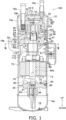
- FIG. 1 is a schematic longitudinal cross-sectional view of the scroll compressor 100.
- the scroll compressor 100 is used in a refrigeration cycle apparatus 1 using a vapor compression refrigeration cycle such as an air conditioner, a hot water supply apparatus, and a floor heating device.
- a vapor compression refrigeration cycle such as an air conditioner, a hot water supply apparatus, and a floor heating device.
- the scroll compressor 100 is mounted in a heat source unit of the refrigeration cycle apparatus 1, and constitutes a part of a refrigerant circuit of the refrigeration cycle apparatus 1.
- the refrigeration cycle apparatus 1 includes, for example, a refrigerant circuit 5 as illustrated in FIG. 10 .
- the refrigerant circuit 5 mainly includes the scroll compressor 100, a condenser (radiator) 2, an expansion device 3, and an evaporator 4.
- the scroll compressor 100, the condenser 2, the expansion device 3, and the evaporator 4 are connected by pipes as illustrated in FIG. 10 .
- the condenser 2 and the evaporator 4 are heat exchangers.
- the expansion device 3 may be an electric expansion valve whose opening degree is variable or a capillary tube.
- the refrigerant circuit 5 includes a subcooling heat exchanger 6 and a bypass expansion device 7.
- the subcooling heat exchanger 6 is a heat exchanger in which a refrigerant flowing through a bypass pipe 8 and a refrigerant flowing through the refrigerant circuit 5 from the condenser 2 to the expansion device 3 exchange heat.
- the bypass pipe 8 is a pipe connecting a branch portion 9, on a pipe connecting the condenser 2 and the expansion device 3 in the refrigerant circuit 5, and a below-mentioned injection pipe 18c of the scroll compressor 100.
- the bypass expansion device 7 is, for example, an electric expansion valve whose opening degree is variable.
- the refrigerant flowing through the refrigerant circuit 5 from the condenser 2 to the expansion device 3 is cooled by heat exchange performed in the subcooling heat exchanger 6, becomes a refrigerant in a subcooled state, and flows to the expansion device 3.
- the refrigerant that has flowed through the bypass pipe 8 has been decompressed to an intermediate pressure in a refrigeration cycle (pressure between high and low pressure in the refrigeration cycle, hereinbelow sometimes simply referred to as an intermediate pressure) in the bypass expansion device 7, and has been subjected to heat exchange with the refrigerant flowing through the subcooling heat exchanger 6 from the condenser 2 to the expansion device 3 is injected into a below-mentioned compression mechanism 20 of the scroll compressor 100.
- the scroll compressor 100 sucks a gas refrigerant having a low pressure in the refrigeration cycle (hereinbelow sometimes simply referred to as a low pressure) and compresses the gas refrigerant in the compression mechanism 20.
- the gas refrigerant having a high pressure in the refrigeration cycle (hereinbelow sometimes simply referred to as a high pressure) compressed in the compression mechanism 20 and discharged from the scroll compressor 100 radiates heat and condenses in the condenser 2 to become a high-pressure liquid refrigerant.
- the refrigerant condensed in the condenser 2 flows to the expansion device 3.
- the low-pressure gas-liquid two-phase refrigerant having flowed through the subcooling heat exchanger 6 and decompressed in the expansion device 3, absorbs heat in the evaporator 4 and evaporates to become a low-pressure gas refrigerant.
- the low-pressure gas refrigerant that has exited the evaporator 4 is sucked into the scroll compressor 100 again and compressed.
- the refrigeration cycle apparatus 1 in a case where the refrigeration cycle apparatus 1 is an air conditioner, during cooling operation, a heat exchanger mounted on a utilization unit functions as the evaporator 4 and a heat exchanger mounted on a heat source unit functions as the condenser 2. Whereas, during heating operation, the heat exchanger mounted on the utilization unit functions as the condenser 2 and the heat exchanger mounted on the heat source unit functions as the evaporator 4.
- the refrigeration cycle apparatus 1 further includes a flow path switching mechanism (not illustrated) such as a four-way switching valve to be used to switch between cooling operation and heating operation.
- the scroll compressor 100 of the present disclosure is a fully hermetic compressor. As described above, the scroll compressor 100 sucks the low-pressure refrigerant, compresses the sucked refrigerant into a high-pressure refrigerant in the refrigeration cycle, and discharges the high-pressure refrigerant.
- the refrigerant is, for example, an HFC refrigerant R32. Note that R32 is merely an example of the refrigerant, and the scroll compressor 100 may be a device that compresses one or more HFC refrigerant other than R32 or one or more HFO refrigerant. Also, for example, the scroll compressor 100 may be a device that compresses and discharges a natural refrigerant such as carbon dioxide.
- the scroll compressor 100 mainly includes a casing 10, the compression mechanism 20, a housing 50, a welding pin 60, a motor 70, a drive shaft 80, and a lower bearing housing 90.
- the scroll compressor 100 includes the casing 10 having a longitudinally elongated cylindrical shape (refer to FIG. 1 ).
- the casing 10 mainly includes a cylindrical member 12, an upper lid 14a, and a lower lid 14b.
- the cylindrical member 12 is a cylindrical member extending along a center axis O and opened on upper and lower sides.
- the upper lid 14a is provided on an upper side of the cylindrical member 12 and closes an upper opening of the cylindrical member 12.
- the lower lid 14b is provided on the lower side of the cylindrical member 12 and closes a lower opening of the cylindrical member 12.
- the cylindrical member 12, the upper lid 14a, and the lower lid 14b are fixed by welding to maintain a hermetic state.
- the casing 10 houses therein various members constituting the scroll compressor 100 including the compression mechanism 20, the housing 50, the motor 70, the drive shaft 80, and the lower bearing housing 90 (refer to FIG. 1 ).
- the compression mechanism 20 is disposed in an upper part of the casing 10.
- the housing 50 is disposed below the compression mechanism 20.
- the motor 70 is disposed below the housing 50.
- the lower bearing housing 90 is disposed below the motor 70.
- An oil reservoir space 16 is formed in a bottom part of the casing 10. Refrigerator oil for lubricating various sliding portions of the scroll compressor 100 is stored in the oil reservoir space 16.
- the motor 70 is disposed in a first space S1 of the scroll compressor 100.
- the first space S1 is a space into which a high-pressure refrigerant compressed by the compression mechanism 20 flows.
- the scroll compressor 100 of the present embodiment is a so-called high-pressure dome-type scroll compressor.
- the first space S1 communicates with the oil reservoir space 16 in a lower part of the casing 10 via a gap or the like formed between the cylindrical member 12 of the casing 10 and a below-mentioned stator 72 of the motor 70 (refer to FIG. 1 ).
- the scroll compressor 100 does not need to be is a high-pressure dome-type scroll compressor.
- the compressor of the present disclosure may be a so-called low-pressure dome-type scroll compressor in which a motor is disposed in a space into which a low-pressure refrigerant flows from the refrigerant circuit 5 of the refrigeration cycle apparatus 1.
- a suction pipe 18a, a discharge pipe 18b, and the injection pipe 18c are attached to the casing 10 so that an inside of the casing 10 communicate with an outside of the casing 10 via these pipes (refer to FIG. 1 ).
- the suction pipe 18a is provided to penetrate the upper lid 14a of the casing 10.
- One end (an end portion outside the casing 10) of the suction pipe 18a is connected to a pipe extending from the evaporator 4 of the refrigerant circuit 5 of the refrigeration cycle apparatus 1, and the other end (an end portion inside the casing 10) of the suction pipe 18a is connected to a suction port 36a of a fixed scroll 30 of the compression mechanism 20.
- the suction pipe 18a communicates with a below-mentioned compression chamber Sc on an outer peripheral side of the compression mechanism 20 via the suction port 36a.
- the scroll compressor 100 sucks a low-pressure refrigerant in the refrigeration cycle of the refrigeration cycle apparatus 1 via the suction pipe 18a.
- the discharge pipe 18b is provided at a center of the cylindrical member 12 in an up-down direction so as to penetrate the cylindrical member 12.
- One end (an end portion outside the casing 10) of the discharge pipe 18b is connected to a pipe extending to the condenser 2 of the refrigerant circuit 5 of the refrigeration cycle apparatus 1, and the other end (an end portion inside the casing 10) of the discharge pipe 18b is disposed between the housing 50 and the motor 70 in the first space S1.
- the scroll compressor 100 discharges a high-pressure refrigerant compressed by the compression mechanism 20 via the discharge pipe 18b.
- the injection pipe 18c is provided to penetrate the upper lid 14a of the casing 10.
- One end (an end portion outside the casing 10) of the injection pipe 18c is connected to the bypass pipe 8 of the refrigerant circuit 5 of the refrigeration cycle apparatus 1, and the other end (an end portion inside the casing 10) of the injection pipe 18c is connected to the fixed scroll 30 of the compression mechanism 20.
- the injection pipe 18c communicates with the compression chamber Sc being in a midstream of compression in the compression mechanism 20 via a not-illustrated passage formed in the fixed scroll 30.
- the compression chamber Sc, with which the injection pipe 18c communicates and which is in the midstream of compression is supplied with an intermediate-pressure refrigerant in the refrigeration cycle from the refrigerant circuit 5 of the refrigeration cycle apparatus 1 via the injection pipe 18c.
- the compression mechanism 20 mainly includes the fixed scroll 30 and a movable scroll 40.
- the fixed scroll 30 and the movable scroll 40 are combined to form the compression chamber Sc.
- the compression mechanism 20 compresses a refrigerant in the compression chamber Sc and discharges the compressed refrigerant.
- the fixed scroll 30 is mounted on and fastened to the housing 50 with a not-illustrated fixing means (for example, a bolt).
- a not-illustrated fixing means for example, a bolt
- the fixed scroll 30 mainly includes a fixed-side end plate 32, a fixed-side wrap 34, and a peripheral edge portion 36.
- the fixed-side end plate 32 is a circular plate-shaped member.
- the fixed-side wrap 34 is a wall-shaped member protruding toward the movable scroll 40 from a front surface 32a (lower surface) of the fixed-side end plate 32.
- the fixed-side wrap 34 is formed in a spiral shape (an involute shape) from a region near a center toward an outer periphery of the fixed-side end plate 32.
- the peripheral edge portion 36 is a thick cylindrical member protruding from the front surface 32a of the fixed-side end plate 32 toward the movable scroll 40.
- the peripheral edge portion 36 is disposed to surround the periphery of the fixed-side wrap 34.
- the peripheral edge portion 36 is provided with the suction port 36a. A downstream end of the suction pipe 18a is connected to the suction port 36a.
- the fixed-side wrap 34 of the fixed scroll 30 and a movable-side wrap 44 of the movable scroll 40 are combined to form the compression chamber Sc.
- the fixed scroll 30 and the movable scroll 40 are combined in a state where the front surface 32a of the fixed-side end plate 32 and a front surface 42a (upper surface) of a movable-side end plate 42 are opposed to each other.
- the compression chamber Sc surrounded by the fixed-side end plate 32, the fixed-side wrap 34, the movable-side wrap 44, and the below-mentioned movable-side end plate 42 of the movable scroll 40 is formed (refer to FIG. 1 ).
- the fixed-side end plate 32 has at its approximately center part a discharge port 33 through which the refrigerant compressed by the compression mechanism 20 is discharged.
- the discharge port 33 is formed to penetrate the fixed-side end plate 32 in a thickness direction (up-down direction) (refer to FIG. 1 ).
- the discharge port 33 communicates with the center-side (innermost-side) compression chamber Sc in the compression mechanism 20.
- a discharge valve 22 that opens and closes the discharge port 33 is attached to an upper side of the fixed-side end plate 32.
- the discharge valve 22 When a pressure in the innermost-side compression chamber Sc, with which the discharge port 33 communicates, is equal to or higher than a pressure in a discharge space Sa above the discharge valve 22 by a predetermined value, the discharge valve 22 is opened to cause the refrigerant in the innermost-side compression chamber Sc to pass through the discharge port 33 and flow into the discharge space Sa above the fixed-side end plate 32.
- the discharge space Sa communicates with a not-illustrated refrigerant passage formed over the fixed scroll 30 and the housing 50.
- the refrigerant passage is a passage that causes the discharge space Sa and the first space S1 below the housing 50 to communicate with each other. The refrigerant compressed by the compression mechanism 20 and then flowing into the discharge space Sa passes through the refrigerant passage and flows into the first space S1.
- the movable scroll 40 mainly includes the movable-side end plate 42, the movable-side wrap 44, and a boss portion 46.
- the movable-side end plate 42 is a circular plate-shaped member.
- the movable-side wrap 44 is a wall-shaped member protruding toward the fixed scroll 30 from the front surface 42a (upper surface) of the movable-side end plate 42.
- the movable-side wrap 44 is formed in a spiral shape (an involute shape) from a region near a center toward an outer periphery of the movable-side end plate 42.
- the boss portion 46 is a cylindrical member protruding from a back surface 42b (lower surface) of the movable-side end plate 42 toward the motor 70.
- the movable scroll 40 While the scroll compressor 100 is operating, the movable scroll 40 is pressed against the fixed scroll 30 by a pressure of a crank chamber 52 and a back pressure space 54, which will be described below, disposed on a side of a back surface 42b of the movable-side end plate 42. Since the movable scroll 40 is pressed against the fixed scroll 30, leakage of the refrigerant from a gap between a tip of the fixed-side wrap 34 and the movable-side end plate 42 and a gap between a tip of the movable-side wrap 44 and the fixed-side end plate 32 is reduced.
- the boss portion 46 is disposed in the below-mentioned crank chamber 52 formed by the housing 50.
- the boss portion 46 is formed in a cylindrical shape.
- the boss portion 46 extends to protrude downward from the back surface 42b of the movable-side end plate 42.
- An upper portion of the cylindrical boss portion 46 is closed by the movable-side end plate 42.
- a bearing metal 47 is disposed in a hollow part of the boss portion 46.
- a below-mentioned eccentric portion 84 of the drive shaft 80 is inserted into the hollow part of the boss portion 46 (refer to FIG. 1 ).
- the drive shaft 80 is connected to a rotor 74 of the motor 70 as described below. Therefore, when the motor 70 is operated and the rotor 74 rotates, the movable scroll 40 turns.
- the movable scroll 40 which is turned by the motor 70, does not rotate by itself but moves in orbit with respect to the fixed scroll 30 by means of an Oldham coupling 24 (refer to FIG. 1 ) disposed on the side of the back surface 42b of the movable scroll 40.
- the gas refrigerant in the compression chamber Sc of the compression mechanism 20 is compressed. More specifically, when the movable scroll 40 moves in orbit, the gas refrigerant is sucked from the suction pipe 18a via the suction port 36a into the peripheral edge-side compression chamber Sc, and thereafter, the compression chamber Sc moves toward a center of the compression mechanism 20 (center of the fixed-side end plate 32). As the compression chamber Sc moves toward the center of the compression mechanism 20, a volume of the compression chamber Sc decreases and a pressure in the compression chamber Sc increases. As a result, the center-side compression chamber Sc has a higher pressure than the peripheral edge-side compression chamber Sc.
- the gas refrigerant compressed by the compression mechanism 20 to have a high pressure is discharged from the center-side compression chamber Sc through the discharge port 33 formed in the fixed-side end plate 32 into the discharge space Sa.
- the refrigerant discharged into the discharge space Sa passes through the not-illustrated refrigerant passage formed through the fixed scroll 30 and the housing 50, and flows into the first space S1 below the housing 50.
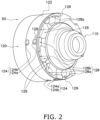
- the housing 50 will be described with reference to FIGS. 2 to 4 as well.
- FIG. 2 is a perspective view of the housing 50 as viewed from below.
- FIG. 3 is a schematic side view of the housing 50.
- FIG. 4 is a schematic view of a fixed state between the casing 10 and the welding pin 60.
- the housing 50 is a cast product. As illustrated in FIG. 1 , the housing 50 mainly includes a main body portion 120 and an upper bearing housing 110.
- the main body portion 120 is a cylindrical part.
- the upper bearing housing 110 also has a cylindrical shape.
- the upper bearing housing 110 is disposed closer to the motor 70 than the main body portion 120 in an axial direction of the drive shaft 80.
- the upper bearing housing 110 is disposed close to the compression mechanism 20 than the motor 70.
- the housing 50 is an example of a support.
- the housing 50 supports a bearing metal 112 provided in the upper bearing housing 110.
- the fixed scroll 30 is fixed to the main body portion 120 of the housing 50. Specifically, the fixed scroll 30 is mounted on the housing 50 in a state where a lower surface of the peripheral edge portion 36 of the fixed scroll 30 is opposed to an upper surface of the housing 50, and is fixed to the housing 50 by a not-illustrated fixing member (for example, a bolt).
- the housing 50 supports the fixed scroll 30 fixed to the main body portion 120.
- the housing 50 also supports the movable scroll 40 disposed between the fixed scroll 30 and the main body portion 120 of the housing 50.
- the housing 50 supports the movable scroll 40 from below via the Oldham coupling 24 disposed on an upper side of the housing 50.
- the main body portion 120 of the housing 50 is a cylindrical member.
- the main body portion 120 of the housing 50 is fixed to an inner peripheral surface of the cylindrical member 12 of the casing 10.
- the housing 50 is press-fitted into the cylindrical member 12 of the casing 10, and an outer peripheral surface of the main body portion 120 is in close contact with an inner peripheral surface of the cylindrical member 12, partially in the axial direction of the drive shaft 80, in entire circumference.
- the housing 50 is further fixed to the cylindrical member 12 of the casing 10 by welding.
- the fixing of the housing 50 to the cylindrical member 12 by welding will specifically be described.
- holes 124 into which the welding pins 60 are press-fitted are formed on an outer surface 122 (outside surface) of the main body portion 120 of the housing 50.
- Each of the holes 124 have a substantially equal shape to a cross section of the welding pin 60 obtained by cutting the welding pin 60 in a direction orthogonal to a press-fitting direction of the welding pin 60 (a direction in which the welding pin 60 is press-fitted into the hole 124).
- each of the holes 124 has a circular shape.
- the holes 124 do not penetrate the main body portion 120 in a radial direction of the cylindrical member 12 of the casing 10.
- the holes 124 are concave portions that do not penetrate the housing 50 in the radial direction of the cylindrical member 12.
- a diameter D of the hole 124 is 12 mm, and a depth A of a portion having the diameter D is 9 mm.
- the depth A of the hole 124 means a depth of the hole 124 from the outer surface 122 to a bottom portion 125 of the hole 124 of the main body portion 120 of the housing 50.
- the bottom portion 125 of the hole 124 means an inner wall portion of the portion having the diameter D of the hole 124 in the radial direction of the cylindrical member 12.
- the holes 124 are formed at a total of eight positions on the outer surface 122 of the housing 50.
- the holes 124 are formed at four locations at intervals of 90° in a circumferential direction. At each of four locations, the holes 124 are formed at two positions in the axial direction (here, an up-down direction) of the drive shaft 80.
- the shapes and dimensions of the holes 124 are all equal. However, the present invention is not limited thereto, and the shape and dimension of the hole 124 may vary depending on the position.
- a hole disposed on an upper side is labeled with reference sign 124b
- a hole disposed on a lower side is labeled with reference sign 124a.
- the hole 124 disposed on the lower side is referred to as a first hole 124a
- the hole 124 disposed on the upper side is referred to as a second hole 124b.
- a low rigidity region 128 is provided at least a part of a periphery of an adjacent portion 126 adjacent to the hole 124 of the housing 50.
- the low rigidity region 128 has lower rigidity than the adjacent portion 126 and including a thin portion 128a to be described below.
- the low rigidity region 128 will be described below.
- a through hole 12a is formed at positions of the cylindrical member 12 of the casing 10 that correspond to the welding pin 60 of the housing 50 press-fitted into the cylindrical member 12 (a position corresponding to the hole 124 of the housing 50) as illustrated in FIG. 4 .
- the welding pin 60 press-fitted into the hole 124 and the cylindrical member 12 of the casing 10 are welded and fixed.
- a portion indicated by reference sign 68 in FIG. 4 indicates a welded portion between the welding pin 60 and the cylindrical member 12.
- housing 50 and the casing 10 are not directly welded, but the welding pin 60 and the casing 10 are welded. This is because the housing 50 is a cast product and it is generally difficult to weld the cast product.
- the housing 50 will further be described.
- the main body portion 120 of the housing 50 includes a first concave portion 56 disposed to be recessed at a center and a second concave portion 58 disposed to surround the first concave portion 56.
- the first concave portion 56 constitutes a side surface of the crank chamber 52 in which the boss portion 46 of the movable scroll 40 is disposed.
- the second concave portion 58 forms the annular back pressure space 54 on the side of the back surface 42b of the movable-side end plate 42.
- the refrigerator oil flows into the crank chamber 52 from the oil reservoir space 16. Therefore, during steady operation of the scroll compressor 100 (in a state where operation of the scroll compressor 100 is stable), a pressure of the crank chamber 52 becomes a high pressure in the refrigeration cycle of the refrigeration cycle apparatus 1. As a result, during the steady operation of the scroll compressor 100, a center portion of the back surface 42b of the movable-side end plate 42 facing the crank chamber 52 is pushed toward the fixed scroll 30 at the high pressure.
- the back pressure space 54 communicates with the compression chamber Sc in the midstream of compression via a not-illustrated hole formed in the movable-side end plate 42 for a predetermined period during one turn of the movable scroll 40. Therefore, during the steady operation of the scroll compressor 100, a pressure in the back pressure space 54 becomes the intermediate pressure in the refrigeration cycle of the refrigeration cycle apparatus 1 (a pressure between the high and low pressure in the refrigeration cycle of the refrigeration cycle apparatus 1). As a result, during the steady operation of the scroll compressor 100, a peripheral edge portion of the back surface 42b of the movable-side end plate 42 facing the back pressure space 54 is pushed toward the fixed scroll 30 at the intermediate pressure.
- the movable scroll 40 is pressed against the fixed scroll 30 by the high pressure in the crank chamber 52 and the intermediate pressure in the back pressure space 54.
- the crank chamber 52 and the back pressure space 54 are separated from each other by an annular wall portion 57 disposed at a boundary between the first concave portion 56 and the second concave portion 58 (refer to FIG. 1 ).
- a not-illustrated seal ring is disposed on an upper end of the wall portion 57 opposed to the back surface 42b of the movable-side end plate 42 so as to seal a space between the crank chamber 52 and the back pressure space 54.
- the upper bearing housing 110 has a cylindrical shape.
- the bearing metal 112 that rotatably supports the drive shaft 80 is provided inside the cylindrical upper bearing housing 110.
- the bearing metal 112 is an example of a bearing.
- An elastic groove 115 is formed in a connection portion between the upper bearing housing 110 and the main body portion 120 so as to allow inclination of the upper bearing housing 110 when the moment acts on the drive shaft 80.
- the welding pin 60 is a member press-fitted into the hole 124 of the main body portion 120 of the housing 50 and a hole 96 of the lower bearing housing 90 described below.
- FIG. 5 is a view of the welding pin 60 before being press-fitted into the hole 124 of the main body portion 120 of the housing 50 or the hole 96 of the lower bearing housing 90 as viewed along the direction orthogonal to the press-fitting direction of the welding pin 60.
- FIG. 6 is a view of the welding pin 60 before being press-fitted into the hole 124 of the main body portion 120 of the housing 50 or the hole 96 of the lower bearing housing 90 as viewed along the press-fitting direction of the welding pin 60.
- the press-fitting direction of the welding pin 60 means a direction in which the welding pin 60 is press-fitted into the hole 124 of the main body portion 120 of the housing 50 or the hole 96 of the lower bearing housing 90.
- the welding pin 60 will be described by taking the welding pin 60 press-fitted into the hole 124 of the main body portion 120 of the housing 50 as an example.
- the welding pin 60 is a substantially cylindrical member. As illustrated in FIG. 6 , the welding pin 60 has a substantially circular shape when viewed along the press-fitting direction of the welding pin 60.
- a concave-convex surface 64 having a concave-convex shape is provided on an outer periphery of the welding pin 60.
- a plurality of grooves 62 are formed along the press-fitting direction of the welding pin 60 on the outer periphery of the welding pin 60.
- a flat knurling is formed on at least a part of an outer peripheral surface of the welding pin 60 by knurling.
- a dimension of the welding pin 60 in a radial direction (direction orthogonal to the press-fitting direction of the welding pin 60), a length L of the welding pin 60 (length in the press-fitting direction of the welding pin 60), and a shape of the welding pin 60 are appropriately designed so that the welding pin 60 can be press-fitted into the hole 124.
- the length L of the welding pin 60 is 8 mm.
- the welding pin 60 is fixed to the main body portion 120 of the housing 50 by being press-fitted into the hole 124 of the main body portion 120 of the housing 50.
- the convex portion 62a of the welding pin 60 is partially plastically deformed.
- the welding pin 60 is expanded due to heat input at a time of welding with the cylindrical member 12 of the casing 10, and the convex portion 62a of the welding pin 60 is pressed against an inner surface of the hole 124, so that the convex portion 62a of the welding pin 60 is further plastically deformed at the time of welding.
- a holding force of the welding pin 60 with respect to the main body portion 120 of the housing 50 may be lower than that before welding because an elasticity of the convex portion 62a is lowered due to plastic deformation.
- the holding force of the welding pin 60 with respect to the main body portion 120 of the housing 50 means a magnitude of a maximum force with which the welding pin 60 does not move in a direction opposite to the press-fitting direction when a force in the direction opposite to the press-fitting direction of the welding pin 60 is applied to the welding pin 60 press-fitted into the main body portion 120.
- the low rigidity region 128 has lower rigidity than the adjacent portion 126 and includes the thin portion 128a to be described below.
- the motor 70 is an example of an actuator.
- the motor 70 includes an annular stator 72 fixed to an inner wall surface of the cylindrical member 12 of the casing 10, and the rotor 74 disposed on an inner side of the stator 72 (refer to FIG. 1 ).
- the rotor 74 is rotatably housed on the inner side of the stator 72 with a small gap (not illustrated) from the stator 72.
- the rotor 74 is coupled to the movable scroll 40 of the compression mechanism 20 via the drive shaft 80.
- the rotor 74 is coupled to the boss portion 46 of the movable scroll 40 via the drive shaft 80 (refer to FIG. 1 ).
- the motor 70 turns the movable scroll 40 by rotating the rotor 74.
- the drive shaft 80 couples the rotor 74 of the motor 70 to the movable scroll 40 of the compression mechanism 20.
- the drive shaft 80 extends in the up-down direction.
- the drive shaft 80 transmits a driving force of the motor 70 to the movable scroll 40 of the compression mechanism 20.
- the drive shaft 80 mainly includes a main shaft 82 and the eccentric portion 84 (refer to FIG. 1 ).
- the main shaft 82 extends in the up-down direction from the oil reservoir space 16 to the crank chamber 52.
- the main shaft 82 is rotatably supported by the bearing metal 112 of the upper bearing housing 110 and a bearing metal 91 disposed in the lower bearing housing 90.
- the main shaft 82 is inserted into and coupled to the rotor 74 of the motor 70 at a position between the upper bearing housing 110 of the housing 50 and the lower bearing housing 90.
- a center axis of the main shaft 82 coincides with the center axis O of the cylindrical member 12 of the casing 10.
- the eccentric portion 84 is disposed at an upper end of the main shaft 82.
- a center axis of the eccentric portion 84 is eccentric to the center axis of the main shaft 82.
- the eccentric portion 84 is inserted into the boss portion 46 of the movable scroll 40 and is rotatably supported by the bearing metal 47 disposed inside the boss portion 46.
- the drive shaft 80 has an oil passage 86.
- the oil passage 86 includes a main passage 86a and a branch passage (not illustrated).
- the main passage 86a extends from a lower end to an upper end of the drive shaft 80 in the axial direction of the drive shaft 80.
- the branch passage branches off the main passage and extends in a direction intersecting with the axial direction of the drive shaft 80.
- the refrigerator oil in the oil reservoir space 16 is pumped up by a pump (not illustrated) disposed at the lower end of the drive shaft 80, and is then supplied to, for example, sliding portions between the drive shaft 80 and the bearing metals 47, 112, and 91, and a sliding portion of the compression mechanism 20, via the oil passage 86.
- the lower bearing housing 90 (refer to FIG. 1 ) is disposed below the motor 70.
- the lower bearing housing 90 mainly includes a main body portion 92 and a plurality of arms 94 extending from the main body portion 92 in the radial direction of the cylindrical member 12 of the casing 10. Although a number is not limited, the lower bearing housing 90 has three arms 94.
- the lower bearing housing 90 is a cast product.
- the main body portion 92 is formed in a cylindrical shape.
- the bearing metal 91 that rotatably supports the drive shaft 80 is provided inside the cylindrical main body portion 92.
- the three arms 94 are provided at substantially equal intervals (at 120° intervals) in a circumferential direction of the cylindrical member 12 of the casing 10.
- the hole 96 into which the welding pin 60 is press-fitted is formed.
- a shape of the hole 96 formed in the arm 94 is equal to the hole 124 formed in the main body portion 120 of the housing 50.
- the shape of the hole 96 formed in the arm 94 is not limited thereto, and for example, the shape of the hole 96 may be different from the hole 124 formed in the main body portion 120 of the housing 50.
- a detailed description of the hole 96 is omitted in order to avoid duplication of description.
- Holes similar to the through hole 12a illustrated in FIG. 4 are formed in the cylindrical member 12 of the casing 10 at a position corresponding to the welding pin 60 of the lower bearing housing 90 (a position corresponding to the hole 96 of the lower bearing housing 90).
- the welding pin 60 and the cylindrical member 12 of the casing 10 are fixed by welding.
- the lower bearing housing 90 is fixed to the cylindrical member 12 of the casing 10 by welding.
- the low rigidity region 128 has lower rigidity than the adjacent portion 126 and includes the thin portion 128a to be described below.
- the reason why the excessive lowering of the holding force of the welding pin 60 is suppressed by providing the low rigidity region 128 is generally as follows.
- the welding pin 60 press-fitted into the hole 124 is welded, the welding pin 60 is thermally expanded by heat input. If the low rigidity region 128 including the thin portion 128a does not exist, a deformation around the hole 124 is relatively strongly restricted. Therefore, a large force acts on the thermally expanded welding pin 60 from the main body portion 120 of the housing 50, and a plastic deformation of the convex portion 62a of the welding pin 60 tends to progress.
- the low rigidity region 128 including the thin portion 128a having lower rigidity than the adjacent portion 126 exists as shown in the present embodiment
- the adjacent portion 126 adjacent to the hole 124 is relatively easily deformed in accordance with the thermal expansion of the welding pin 60. Therefore, a force exerted on the welding pin 60 by the adjacent portion 126 becomes relatively small, and the plastic deformation of the convex portion 62a of the welding pin 60 tends to be suppressed.
- the low rigidity region 128 including the thin portion 128a is a deformation allowing region that allows deformation of the housing 50 when the welding pin 60 is thermally expanded.
- the low rigidity regions 128 are disposed around the first holes 124a out of the holes 124 of the main body portion 120 of the housing 50 provided at two positions in the axial direction of the drive shaft 80 at each of four locations in the circumferential direction of the cylindrical member 12 of the casing 10.
- the first hole 124a is a hole disposed closest to the bearing metal 112 in the axial direction of the drive shaft 80 out of the two holes 124 provided in the axial direction of the drive shaft 80.
- FIG. 7 is a schematic partial cross-sectional view taken along line VII-VII in FIG. 1 .
- the welding pin 60 is not drawn.
- FIG. 8 is a schematic partial longitudinal cross-sectional view for explaining an overlapping state between a region where a downgage 129 to be described below exists and a region where the welding pin 60 exists.
- the adjacent portion 126 exists at a position adjacent to the first hole 124a of the main body portion 120 of the housing 50.
- the adjacent portion 126 is disposed so as to surround an entire circumference of the first hole 124a when the first hole 124a formed in the outer surface 122 of the main body portion 120 is viewed from a position just facing the first hole 124a.
- a member cast product constituting the housing 50 exists from the outer surface 122 of the main body portion 120 of the housing 50 to at least a position of the depth A of the first hole 124a.
- the adjacent portion 126 has a thickness of at least "A" in the radial direction of the cylindrical member 12 of the casing 10.
- the member in the adjacent portion 126, exists in a range from the outer surface 122 of the main body portion 120 to the crank chamber 52 in the radial direction of the cylindrical member 12 of the casing 10.
- a member having a thickness of K at minimum exists in the radial direction of the cylindrical member 12 of the casing 10.
- the low rigidity region 128 having lower rigidity than the adjacent portion 126 is provided in at least a part of the periphery of the adjacent portion 126.
- the low rigidity region 128 includes the thin portion 128a having a smaller thickness in the radial direction of the cylindrical member 12 of the casing 10 than the adjacent portion 126.
- the low rigidity region 128 includes a void portion 128b in which the main body portion 120 (member constituting the main body portion 120) does not exist.
- the thin portion 128a is disposed, so as to interpose the first hole 124a, on both sides of the first hole 124a in the circumferential direction of the cylindrical member 12 of the casing 10 (refer to FIGS. 2 and 3 ).
- the thin portion 128a is an example of a first portion.
- the downgage 129 is formed closer to the center axis O (refer to FIG. 3 ) of the cylindrical member 12 of the casing 10 than the outer surface 122 of the main body portion 120 of the housing 50.
- a concave portion 129 is formed closer to the center axis O of the cylindrical member 12 of the casing 10 than the outer surface 122 of the main body portion 120 of the housing 50 (refer to FIG. 7 ).
- the downgage 129 is disposed on both sides of each of the four first holes 124a in the circumferential direction of the cylindrical member 12 of the casing 10 so as to interpose the first hole 124a.
- the downgage 129 that is, the concave portion 129, is formed from a bottom portion of the main body portion 120 of the housing 50 to an intermediate portion between the first hole 124a and the second hole 124b in the axial direction of the drive shaft 80 (refer to FIGS. 3 and 8 ).
- the downgage 129 may be provided during casting or by machining the cast product.
- a thickness M of the thin portion 128a of the casing 10 in the radial direction of the cylindrical member 12 is smaller than a minimum thickness K of the adjacent portion 126.
- the thickness M of the thin portion 128a in the radial direction of the cylindrical member 12 means a total thickness of a portion where a member exists, disposed between the outer surface 122 of the main body portion 120 and the crank chamber 52 in the circumferential direction of the cylindrical member 12.
- a total of a thickness M1 and a thickness M2 is the thickness M of the thin portion 128a in the radial direction of the cylindrical member 12.
- the thickness M of the thin portion 128a does not need to be uniform as illustrated in FIG. 8 , or the thin portion 128a may be formed so that the thickness M is uniform.
- the thickness M1 from the outer surface 122 of the main body portion 120 to the downgage 129 is smaller than the depth A of the first hole 124a in the radial direction of the cylindrical member 12 of the casing 10.
- the region where the downgage 129 exists and the region where the welding pin 60 press-fitted into the first hole 124a exists preferably overlap with each other in a range of 10% or more of a length of the welding pin 60 press-fitted into the first hole 124a in the radial direction of the cylindrical member 12 of the casing 10 (in other words, the length L of the welding pin 60 in the press-fitting direction). It is assumed that the welding pin 60 is press-fitted to a position where the welding pin abuts against the bottom portion 125 of the first hole 124a.
- a value B obtained by subtracting the thickness M1 from the outer surface 122 of the main body portion 120 to the downgage 129 in the thin portion 128a from the depth A of the first hole 124a is preferably 10% or more of the length L of the welding pin 60 in the press-fitting direction. More specifically, for example, in the radial direction of the cylindrical member 12 of the casing 10, a value obtained by subtracting an average of the thicknesses from the outer surface 122 of the main body portion 120 to the downgage 129 in the thin portion 128a from the depth A of the first hole 124a is preferably 10% or more of the length L of the welding pin 60 in the press-fitting direction.
- the void portion 128b is disposed closer to the motor 70 than the first hole 124a in the axial direction of the drive shaft 80. In other words, the void portion 128b is disposed below the first hole 124a in the axial direction of the drive shaft 80. In short, as illustrated in FIG. 4 , the main body portion 120 (member constituting the main body portion 120) does not exist in at least a partial region below the adjacent portion 126 below the first hole 124a.
- a thickness C of the main body portion 120 outside a position of the bottom portion 125 of the first hole 124a in the radial direction of the cylindrical member 12 of the casing 10 at a height position where the void portion 128b exists below the adjacent portion 126 below the first hole 124a is smaller than the depth A of the first hole 124a (refer to FIG. 4 ).
- FIG. 4 a mode in which the main body portion 120 exists in a partial region immediately below the adjacent portion 126 adjacent below the first hole 124a is illustrated, but the present invention is not limited thereto.
- the main body portion 120 does not need to exist immediately below the adjacent portion 126 adjacent below the first hole 124a. In other words, for example, only the void portion 128b may be disposed immediately below the adjacent portion 126 adjacent below the first hole 124a.
- the low rigidity region 128 is provided in a region (angular region indicated by " ⁇ " in FIG. 3 ) at 180° or more around a center of the first hole 124a when the first hole 124a is viewed from a position just facing the first hole 124a (when the first hole 124a is viewed from its front in a horizontal direction orthogonal to the axial direction of the drive shaft 80).
- a ratio of a minimum distance d from the first hole 124a to the low rigidity region 128 to the diameter D of the first hole 124a is preferably 0.25 or more and 0.85 or less.
- the minimum distance d from the first hole 124a to the low rigidity region 128 is preferably 3.0 mm or more and 10.2 mm or less.
- the downgage 129 is preferably disposed to be away from the first hole 124a by 3.0 mm or more and not to be away from the first hole 124a by more than 10.2 mm.
- the void portion 128b is preferably disposed to be away from the first hole 124a by 3.0 mm or more and not to be away from the first hole 124a by more than 10.2 mm.
- the first hole 124a away from the low rigidity region 128 by 3.0 mm or more that is, by providing the adjacent portion 126 of 3.0 mm or more around the first hole 124a, it is possible to avoid a problem that a rigidity of the adjacent portion 126 is lowered and the welding pin 60 cannot firmly be held.
- the ratio of the minimum distance d from the first hole 124a to the low rigidity region 128 to the diameter D of the first hole 124a to 0.25 or more and providing the adjacent portion 126 of 0.25 ⁇ D or more around the first hole 124a, it is possible to avoid a problem that the rigidity of the adjacent portion 126 is excessively lowered and the welding pin 60 cannot be held.
- the minimum distance d from the first hole 124a to the low rigidity region 128 is designed in a range of 5 mm to 7 mm.
- the ratio of the minimum distance d from the first hole 124a to the low rigidity region 128 to the diameter D of the first hole 124a is preferably in a range of 0.42 to 0.58.
- a comparison experiment of the holding force of the welding pin 60 press-fitted into the first hole 124a was conducted between a case where the thin portion 128a is provided in the scroll compressor 100 and a case where the thin portion 128a is not provided in the scroll compressor 100.
- the comparative experiment was performed under an equal condition except whether or not to provide the thin portion 128a (for example, dimensions and materials of the welding pin 60 and the main body portion 120, welding conditions, and the like and the like are set to the same in the both experiments).
- an average value P2 of the holding forces of the welding pins 60 press-fitted into the first holes 124a in the case where the thin portion 128a is provided is about 1.75 times an average value P1 of the holding forces of the welding pins 60 press-fitted into the first holes 124a in the case where the thin portion 128a is not provided (P2 ⁇ 1.75 P1).
- the intermediate-pressure (pressure between high and low pressure) refrigerant in the refrigeration cycle of the refrigeration cycle apparatus 1 is injected into the compression chamber Sc in the midstream of compression from the injection pipe 18c as needed.
- the pressure of the refrigerant increases as the refrigerant approaches the center-side (inner side) compression chamber Sc from the peripheral edge-side (outer side) compression chamber Sc and finally becomes a high pressure in the refrigeration cycle of the refrigeration cycle apparatus 1.
- the refrigerant compressed by the compression mechanism 20 is discharged from the discharge port 33 located near a center of the fixed-side end plate 32, passes through the not-illustrated refrigerant passage formed through the fixed scroll 30 and the housing 50, and flows into the first space S1.
- the high-pressure refrigerant in the refrigeration cycle is discharged from the first space S1 through the discharge pipe 18b.
- the scroll compressor 100 of the present embodiment includes the motor 70 as an example of a actuator, the compression mechanism 20, the drive shaft 80, the housing 50 as an example of a support, the casing 10, and the welding pin 60.
- the drive shaft 80 transmits a driving force of the motor 70 to the compression mechanism 20.
- the housing 50 supports the bearing metal 112 (a bearing metal 112 provided in an upper bearing housing 110) as an example of a bearing that rotatably supports the drive shaft 80.
- At least one hole 124 is formed in the outer surface 122 of the main body portion 120 of the housing 50.
- the casing 10 accommodates the drive shaft 80 and the housing 50 therein.
- the casing 10, in particular, the cylindrical member 12, has a cylindrical shape.
- the concave-convex surface 64 having a concave-convex shape is provided on the outer periphery of the welding pin 60.
- the welding pin 60 is press-fitted into the hole 124 of the housing 50 and is welded and fixed to the casing 10. At least a part of the periphery of the adjacent portion adjacent to the hole 124 of the housing 50, particularly in the present embodiment, at least a part of the periphery of the adjacent portion 126 adjacent to a first hole 124a, is provided with the low rigidity region 128 having lower rigidity than the adjacent portion 126.
- the low rigidity region 128 includes the thin portion 128a having a smaller thickness in the radial direction of the casing 10 than the adjacent portion 126.
- the periphery of the adjacent portion 126 adjacent to the hole 124 of the housing 50 into which the welding pin 60 is press-fitted is provided with the low rigidity region 128 including the thin portion 128a and having lower rigidity than the adjacent portion 126.
- the housing 50 can deform when the welding pin 60 is thermally expanded at a time of welding, and plastic deformation of a convex portion 62a of a concave-convex surface 64 of the welding pin 60 can be suppressed.
- a relatively large holding force of the welding pin 60 can be maintained after welding.
- the downgage 129 is formed closer to a center axis O of the casing 10 than the outer surface 122 of the main body portion 120 of the housing 50.
- the scroll compressor 100 of the present embodiment by forming the downgage 129 around the adjacent portion 126, it is possible to suppress plastic deformation of the convex portion 62a of the concave-convex surface 64 of the welding pin 60 when the welding pin 60 is thermally expanded.
- the low rigidity region 128 is provided in a region at 180° or more around a center of the first hole 124a.
- the housing 50 can deform when the welding pin 60 is thermally expanded and plastic deformation of the convex portion 62a of the concave-convex surface 64 of the welding pin 60 may be suppressed.
- the scroll compressor 100 of the present embodiment can maintain a strength of the housing 50 holding the welding pin 60.
- the low rigidity region 128 is disposed relatively close to the first hole 124a.
- the plurality of holes 124 are disposed in an axial direction of the drive shaft 80.
- the first hole 124a and the second hole 124b are provided in the axial direction of the drive shaft 80.
- the low rigidity region 128 having lower rigidity than the adjacent portion 126 is provided at least a part of the periphery of the adjacent portion 126 (an example of the first adjacent portion) adjacent to the first hole 124a disposed closest to the bearing metal 112 in the axial direction of the drive shaft 80 among the holes.
- the low rigidity region 128 is provided at least around the first hole 124a where the welding pin 60 may receive a largest force (moment) during operation of the compressor. As a result, it is possible to suppress lowering of the holding force of the welding pin 60 press-fitted into the first hole 124a after welding.
- the compressor of the present embodiment is the scroll compressor 100, and the housing 50 supports the bearing (bearing metal 112) disposed closer to the compression mechanism 20 than the motor 70.
- the scroll compressor 100 of the present embodiment can suppress lowering of the holding force of the welding pin 60 after welding, which is used for the housing 50 of the scroll compressor 100 on which a large force tends to act.
- the low rigidity region 128 includes the thin portion 128a as an example of a first portion and the void portion 128b as an example of a second portion.
- the thin portion 128a is disposed, so as to interpose the first hole 124a, on both sides of the first hole 124a in a circumferential direction of the cylindrical member 12 of the casing 10.
- the void portion 128b is disposed closer to the motor 70 than the first hole 124a in the axial direction of the drive shaft 80.
- the housing 50 can deform relatively largely when the welding pin 60 is thermally expanded and it is possible to suppress plastic deformation of the convex portion 62a of the concave-convex surface 64 of the welding pin 60.
- the downgage 129 is disposed, so as to interpose the first hole 124a, on both sides of the first hole 124a in the circumferential direction of the cylindrical member 12 of the casing 10.
- the welding pin 60 has the first length L in the radial direction of the cylindrical member 12 of the casing 10. In other words, the welding pin 60 has the first length L in the press-fitting direction.
- the region where the downgage 129 exists and the region where the welding pin 60 exists overlap with each other in a range of 10% or more of the first length L.
- the region where the downgage 129 exists and the region where the welding pin 60 exists overlap with each other in the range of 10% or more of the first length L of the welding pin 60. Therefore, plastic deformation of the convex portion 62a of the concave-convex surface 64 of the welding pin 60 is easily suppressed when the welding pin 60 is thermally expanded.
- the compressor has been described by taking the scroll compressor 100 as an example, but the type of compressor is not limited to the scroll compressor.
- the configuration of the present disclosure in which the low rigidity region is provided in the support that supports the bearing that rotatably supports the drive shaft is widely applicable to a compressor in which a hole for press-fitting a welding pin is provided in a support, and the welding pin and a casing are fixed by welding.
- the compressor of the present disclosure may be a rotary compressor.
- the thin portion 128a is provided on both sides of the first hole 124a of the main body portion 120 of the housing 50 in the circumferential direction of the cylindrical member 12 of the casing 10.
- the thin portion 128a is not provided on both sides of the second hole 124b (the hole disposed above the first hole 124a) of the main body portion 120 of the housing 50.
- the present invention is not limited thereto, and for example, the thin portion 128a may be provided on both sides of the adjacent portion of the second hole 124b of the main body portion 120 of the housing 50 in the circumferential direction of the cylindrical member 12 of the casing 10 by increasing a depth of the downgage 129.
- the housing 50 can be deformed to suppress plastic deformation of the convex portion 62a of the concave-convex surface 64 of the welding pin 60.
- the holes 124 are provided at two positions in the axial direction of the drive shaft 80 at each of four locations in the circumferential direction of the cylindrical member 12 of the casing 10.
- the present invention is not limited thereto, and for example, in the main body portion 120 of the housing 50, the hole 124 may be provided at only one position at each of four locations in the circumferential direction of the cylindrical member 12 of the casing 10.
- the welding pins 60 press-fitted into the second hole 124b and the second hole 124b in the above embodiment may be omitted.
- three or more holes 124 may be provided at each of four locations in the circumferential direction of the cylindrical member 12 of the casing 10.
- at least a part of the periphery of the adjacent portion adjacent to the hole 124 disposed closest to the bearing metal 112 in the axial direction of the drive shaft 80 among the holes 124 is preferably provided with the low rigidity region having lower rigidity than the adjacent portion.
- the holes 124 are provided at two positions in the axial direction of the drive shaft 80 so that the holes 124 are arrayed in the axial direction of the drive shaft 80 at each of four locations in the circumferential direction of the cylindrical member 12 of the casing 10.
- the present invention is not limited thereto, and for example, the hole 124 disposed on the lower side of the main body portion 120 of the housing 50 (the first hole 124a in the above embodiment) and the hole 124 disposed on the upper side of the main body portion 120 of the housing 50 (the second hole 124b in the above embodiment) may be disposed at different positions in the circumferential direction of the cylindrical member 12 of the casing 10.
- the thin portion 128a of the low rigidity region 128 is formed by forming the downgage 129 closer to the center axis O of the casing 10 than the outer surface 122 of the housing 50.
- a method of forming the thin portion 128a is not limited thereto.
- a thin portion 228a may be provided by providing a groove 229 on the outer surface 122 of the main body portion 220 of the housing 250 instead of the downgage 129.
- the groove 229 is provided on both sides of the hole 124 (the first hole 124a and the second hole 124b) in the circumferential direction of the cylindrical member 12 of the casing 10 so as to interpose the hole 124.
- the groove 229 is recessed radially inward of the casing 10 with respect to the outer surface 122 of the main body portion 220 and extends along the axial direction of the drive shaft 80.
- a thickness of the thin portion 228a in the radial direction of the cylindrical member 12 of the casing 10 is smaller than the minimum thickness K of the adjacent portion 126.
- a thickness from a bottom portion of the groove 229 to a position where the bottom portion 125 of the hole 124 exists is smaller than the depth A of the hole 124 in the radial direction of the cylindrical member 12 of the casing 10.
- a member having the thickness A exists from the position where the bottom portion 125 of the hole 124 to the outer surface 122 of the main body portion 120, whereas a thickness from the position where the bottom portion 125 of the hole 124 exists to the bottom portion of the groove 229 of the thin portion 228a is smaller than the thickness A.
- the thickness of the thin portion 228a existing further on an outer side than the position of the bottom portion 125 of the hole 124 is thinner than the depth A of the hole 124 by a depth of the groove 229 in the radial direction of the cylindrical member 12 of the casing 10.
- a region where the groove 229 exists and the region where the welding pin 60 press-fitted into the hole 124 exists preferably overlap with each other in a range of 10% or more of the length of the welding pin 60 press-fitted into the hole 124 in the radial direction of the cylindrical member 12 of the casing 10 (in other words, the length L of the welding pin 60 in the press-fitting direction).
- the welding pin 60 is press-fitted to a position where the welding pin abuts against the bottom portion 125 of the hole 124.
- the low rigidity region 228 provided in the main body portion 220 of the housing 250 of the present modification includes the void portion 128b in addition to the thin portion 228a. Description of the void portion 128b is omitted since the void portion 128b is similar to that in the above embodiment.
- the housing 250 when the welding pin 60 is thermally expanded at the time of welding to the casing 10, the housing 250 can be deformed to suppress plastic deformation of the convex portion 62a of the concave-convex surface 64 of the welding pin 60.
- a relatively large holding force of the welding pin 60 after welding can be maintained.
- the housing 250 can be deformed to suppress plastic deformation of the convex portion 62a of the concave-convex surface 64 of the welding pin 60.
- a relatively large holding force of the welding pin 60 after welding can be maintained.
- the thin portion 128a formed by providing the downgage 129 as in the above embodiment and the thin portion 228a formed by providing the groove 229 as in the present modification example may be mixed.
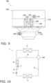
- a groove 230 may further be provided along the circumferential direction of the cylindrical member 12 of the casing 10 between the first hole 124a and the second hole 124b (refer to a broken line in FIG. 9 ).
- the housing 50 is fixed by press fitting and welding.
- the present invention is not limited thereto, and for example, the housing 50 may be fixed to the casing 10 only by welding (only by welding of the welding pin 60 press-fitted into the hole 124 of the main body portion 120 and the casing 10).
- the vertical scroll compressor in which the axial direction of the drive shaft 80 is a vertical direction is described as an example, but the compressor may be a horizontal compressor in which the axial direction of the drive shaft 80 is a horizontal direction.
- the low rigidity region 128 when the first hole 124a is viewed from a position just facing the first hole 124a, the low rigidity region 128 is provided in the region at 180° or more around the center of the first hole 124a, but the present invention is not limited thereto.
- the low rigidity region 128 may be provided in a region smaller than the region at 180° around the center of the first hole 124a.
- the low rigidity region 128 in the region at 180° or more around the center of the first hole 124a when the first hole 124a is viewed from a position just facing the first hole 124a, plastic deformation of the convex portion 62a of the concave-convex surface 64 of the welding pin 60 press-fitted into the first hole 124a tends to be particularly suppressed.
- the housing 50 and the lower bearing housing 90 support the bearing metal 112 and the bearing metal 91 as examples of bearings, respectively, but the present invention is not limited thereto.
- the housing 50 and the lower bearing housing 90 may support roller bearings such as ball bearings instead of the bearing metals 112 and 91.
- the scroll compressor of the present disclosure is described by taking, as an example, a case where the welding pin 60 has the concave-convex surface 64 having a concave-convex shape on the outer periphery.
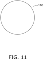
- the welding pin before press-fitting used in the scroll compressor of the present disclosure may be a cylindrical welding pin 160 not having the concave-convex surface 64.
- the welding pin 160 before press-fitting may have a circular shape when viewed along the press-fitting direction.
- a scroll compressor according to the modification example J described herein is similar to the scroll compressor of the above embodiment except for the welding pin 160.
- a scroll compressor 100 of the modification example J includes a motor 70, a compression mechanism 20, a drive shaft 80, a housing 50, a casing 10, and a welding pin 160.
- the drive shaft 80 transmits a driving force of the motor 70 to the compression mechanism 20.
- the housing 50 supports a bearing metal 112, provided in an upper bearing housing 110, that rotatably supports the drive shaft 80.
- At least one hole 124 is formed in an outer surface 122 of a main body portion 120 of the housing 50.
- the casing 10 accommodates the drive shaft 80 and the housing 50 therein.
- the casing 10, in particular, a cylindrical member 12, has a cylindrical shape.
- the welding pin 160 is press-fitted into the hole 124 of the housing 50 and is welded and fixed to the casing 10.
- a low rigidity region 128 is provided at least a part of a periphery of an adjacent portion adjacent to the hole 124 of the housing 50, particularly in the present embodiment, at least a part of a periphery of an adjacent portion 126 adjacent to a first hole 124a.
- the low rigidity region 128 has lower rigidity than the adjacent portion 126.
- the low rigidity region 128 includes a thin portion 128a having a smaller thickness in a radial direction of the casing 10 than the adjacent portion 126.
- the housing 50 can deform when the welding pin 160 is thermally expanded during welding, and excessive plastic deformation of the welding pin 160 can be suppressed. As a result of suppressing the plastic deformation of the welding pin 160, a relatively large holding force of the welding pin 160 after welding can be maintained.
- the scroll compressor 100 according to the modification example J preferably has the characteristics described in (5-2) to (5-8) of the above embodiment except that the welding pin 160 does not have the concave-convex surface.
- the present disclosure is widely applicable and useful to a compressor in which a welding pin is press-fitted into a hole on an outer surface of a support that supports a bearing, and the welding pin and a casing are welded and fixed.
- Patent Literature 1 JP 2017-25762 A
Landscapes
- Engineering & Computer Science (AREA)
- Mechanical Engineering (AREA)
- General Engineering & Computer Science (AREA)
- Physics & Mathematics (AREA)
- Thermal Sciences (AREA)
- Applications Or Details Of Rotary Compressors (AREA)
- Rotary Pumps (AREA)
- Compressor (AREA)
Abstract
Description
- The present disclosure relates to a compressor and a refrigeration cycle apparatus including the compressor. Specifically, the present disclosure relates to a compressor in which a welding pin is press-fitted into a hole on an outer surface of a support that supports a bearing, and the welding pin and a casing are welded and fixed to each other, and a refrigeration cycle apparatus including the compressor.
- Conventionally, as in Patent Literature 1 (
JP 2017-25762A - In such a compressor, when the welding pin is press-fitted into the support, the welding pin is plastically deformed. Also, when the welding pin and the casing are welded, the welding pin is pressed against the support by thermal expansion of the welding pin, and the welding pin is further plastically deformed. When the welding pin is excessively plastically deformed, a holding force of the welding pin after welding may decrease.
- A compressor according to a first aspect includes an actuator, a compression mechanism, a drive shaft, a support, a casing, and a welding pin. The drive shaft transmits a driving force of the actuator to the compression mechanism. The support supports a bearing that is configured to rotatably support the drive shaft. At least one hole is formed in an outer surface of the support. The casing accommodates the drive shaft and the support therein. The casing has a cylindrical shape. The welding pin is press-fitted into the hole of the support and is welded and fixed to the casing. A low rigidity region is provided at least a part of a periphery of an adjacent portion adjacent to the hole of the support. The low rigidity region has lower rigidity than the adjacent portion. The low rigidity region includes a thin portion having a smaller thickness in a radial direction of the casing than the adjacent portion.
- In the compressor according to the first aspect, the periphery of the adjacent portion adjacent to the hole of the support into which the welding pin is press-fitted is provided with the low rigidity region including the thin portion and having lower rigidity than the adjacent portion. By providing the low rigidity region, the support can deform when the welding pin is thermally expanded at a time of welding, and excessive plastic deformation of the welding pin can be suppressed. As a result of suppressing the plastic deformation of the welding pin, a relatively large holding force of the welding pin can be maintained after welding.
- A compressor according to a second aspect is the compressor according to the first aspect, wherein, in the low rigidity region, a downgage is formed closer to a center axis of the casing than the outer surface of the support.
- In the compressor according to the second aspect, by forming the downgage around the adjacent portion, it is possible to suppress excessive plastic deformation of the welding pin when the welding pin is thermally expanded.
- A compressor according to a third aspect is the compressor according to the first or second aspect, wherein, when the hole is viewed from a position just facing the hole, the low rigidity region is provided in a region at 180° or more around a center of the hole.
- In the compressor according to the third aspect, by providing the low rigidity region in the region at 180° or more around the center of the hole, the support can deform when the welding pin is thermally expanded and excessive plastic deformation of the welding pin is suppressed.
- A compressor according to a fourth aspect is the compressor according to any one of the first to third aspects, wherein a ratio of a minimum distance from the hole to the low rigidity region to a diameter of the hole is 0.25 or more and 0.85 or less.
- By setting the ratio of the minimum distance from the hole to the low rigidity region to the diameter of the hole to 0.25 or more, the compressor according to the fourth aspect can maintain a strength of the support that holds the welding pin.
- Further, in the compressor according to the fourth aspect, the ratio of the minimum distance from the hole to the low rigidity region to the diameter of the hole is 0.85 or less. In other words, in the compressor according to the fourth aspect, the low rigidity region is disposed relatively close to the hole. As a result, when the welding pin is thermally expanded, the support can deform and excessive plastic deformation of the welding pin can be suppressed.
- A compressor according to a fifth aspect is the compressor according to any one of the first to fourth aspects, wherein the plurality of holes are disposed in an axial direction of the drive shaft. The low rigidity region is provided at least a part of a periphery of a first adjacent portion adjacent to a first hole disposed closest to the bearing in the axial direction of the drive shaft among the holes. The low rigidity region has lower rigidity than the first adjacent portion.
- In the compressor according to the fifth aspect, the low rigidity region is provided at least around the first hole where the welding pin may receive a largest force (moment) during operation of the compressor. As a result, it is possible to suppress lowering of the holding force of the welding pin press-fitted into the first hole after welding.
- A compressor according to a sixth aspect is the compressor according to any one of the first to fifth aspects, wherein the compressor is a scroll compressor. The support supports the bearing disposed closer to the compression mechanism than the actuator.
- The compressor according to the sixth aspect can suppress lowering of the holding force of the welding pin after welding, which is used for the support of the scroll compressor on which a large force tends to act.
- A compressor according to a seventh aspect is the compressor according to any one of the first to sixth aspects, wherein the low rigidity region includes a first portion and a second portion. The first portion is disposed, so as to interpose the hole, on both sides of the hole in a circumferential direction of the casing. The second portion is disposed closer to the actuator than the hole in the axial direction of the drive shaft.
- In the compressor according to the seventh aspect, as the low rigidity region is disposed so as to surround the hole on three sides, the support can deform relatively largely when the welding pin is thermally expanded and it is possible to suppress excessive plastic deformation of the welding pin.
- A compressor according to an eighth aspect is the compressor according to the second aspect, wherein the downgage is disposed, so as to interpose the hole, on both sides of the hole in a circumferential direction of the casing. The welding pin has a first length in a radial direction of the casing. In the radial direction of the casing, a region where the downgage exists and a region where the welding pin exists overlap with each other in a range of 10% or more of the first length.
- In the compressor according to the eighth aspect, in the radial direction of the casing, the region where the downgage exists and the region where the welding pin exists overlap with each other in the range of 10% or more of the first length of the welding pin. Therefore, when the welding pin is thermally expanded, it is easy to suppress excessive plastic deformation of the welding pin.
- A compressor according to a ninth aspect is the compressor according to any one of the first to eighth aspects, wherein the welding pin has a concave-convex surface having a concave-convex shape on an outer periphery thereof.
- In some cases, the concave-convex surface is provided on the outer periphery of the welding pin. In a case where the welding pin has the concave-convex surface on the outer periphery, a convex portion of the concave-convex surface particularly tends to be plastically deformed when the welding pin is press-fitted into the support. Also, when the welding pin and the casing are welded, the convex portion of the concave-convex surface of the welding pin is pressed against the support by thermal expansion, and the convex portion is further plastically deformed. In a case where the convex portion is excessively plastically deformed, and an elasticity of the convex portion is lost, the holding force (force to fix the welding pin to the support) of the welding pin after welding may be lowered.
- To solve this, in the compressor according to the ninth aspect, around the adjacent portion adjacent to the hole of the support into which the welding pin is press-fitted, the low rigidity region having lower rigidity than the adjacent portion is provided. Therefore, when the welding pin is thermally expanded during welding, the support can deform to suppress excessive plastic deformation of the convex portion of the concave-convex surface. As a result, a relatively large holding force of the welding pin after welding can be maintained.
- A refrigeration cycle apparatus according to a tenth aspect includes a refrigerant circuit that includes the compressor according to any one of the first to ninth aspects.
-
-
FIG. 1 is a schematic longitudinal cross-sectional view of a scroll compressor according to one embodiment of the present disclosure. -
FIG. 2 is a perspective view of a housing of the scroll compressor inFIG. 1 as viewed from below. -
FIG. 3 is a schematic side view of the housing of the scroll compressor inFIG. 1 . -
FIG. 4 is a schematic view of a fixed state between a casing and a welding pin of the scroll compressor inFIG. 1 . -
FIG. 5 is a view of the welding pin before being press-fitted used in the scroll compressor inFIG. 1 , as viewed along a direction orthogonal to a press-fitting direction of the welding pin. -
FIG. 6 is a view of the welding pin before being press-fitted used in the scroll compressor inFIG. 1 , as viewed along the press-fitting direction of the welding pin. -
FIG. 7 is a schematic partial cross-sectional view taken along line VII-VII inFIG. 1 , in which the welding pin is not drawn. -
FIG. 8 is a schematic partial longitudinal cross-sectional view for explaining an overlapping state between a region where a downgage exists and a region where the welding pin exists in the scroll compressor inFIG. 1 . -
FIG. 9 is a schematic side view of a housing of a scroll compressor according to a modification example E. -
FIG. 10 is a schematic configuration diagram of a refrigeration cycle apparatus including the scroll compressor inFIG. 1 . -
FIG. 11 is a view of the welding pin before being press-fitted used in a scroll compressor according to a modification example J, as viewed along the press-fitting direction of the welding pin. - An embodiment of a compressor will be described below with reference to the drawings.
- The following description may include expressions such as "up" and "down" to describe positions and orientations for convenience of description. Unless otherwise noted, the positions and the orientations represented by the expressions such as "up" and "down" follow arrows in figures.
- Also, in the following description, expressions such as "parallel", "orthogonal", "horizontal", "vertical", and "identical" may be used, but these expressions do not necessarily mean parallel, orthogonal, horizontal, vertical, and identical in a strict meaning. The meanings of the expressions such as "parallel", "orthogonal", "horizontal", "vertical", and "identical" include substantially parallel, orthogonal, horizontal, vertical, and identical when these expressions are used.
- An outline of a
scroll compressor 100 as an embodiment of a compressor of the present disclosure will be described with reference toFIG. 1. FIG. 1 is a schematic longitudinal cross-sectional view of thescroll compressor 100. - The
scroll compressor 100 is used in arefrigeration cycle apparatus 1 using a vapor compression refrigeration cycle such as an air conditioner, a hot water supply apparatus, and a floor heating device. For example, thescroll compressor 100 is mounted in a heat source unit of therefrigeration cycle apparatus 1, and constitutes a part of a refrigerant circuit of therefrigeration cycle apparatus 1. - The
refrigeration cycle apparatus 1 includes, for example, a refrigerant circuit 5 as illustrated inFIG. 10 . The refrigerant circuit 5 mainly includes thescroll compressor 100, a condenser (radiator) 2, anexpansion device 3, and anevaporator 4. In the refrigerant circuit 5, thescroll compressor 100, the condenser 2, theexpansion device 3, and theevaporator 4 are connected by pipes as illustrated inFIG. 10 . The condenser 2 and theevaporator 4 are heat exchangers. For example, theexpansion device 3 may be an electric expansion valve whose opening degree is variable or a capillary tube. - As an optional configuration, in the present embodiment, the refrigerant circuit 5 includes a
subcooling heat exchanger 6 and abypass expansion device 7. Thesubcooling heat exchanger 6 is a heat exchanger in which a refrigerant flowing through abypass pipe 8 and a refrigerant flowing through the refrigerant circuit 5 from the condenser 2 to theexpansion device 3 exchange heat. Thebypass pipe 8 is a pipe connecting abranch portion 9, on a pipe connecting the condenser 2 and theexpansion device 3 in the refrigerant circuit 5, and a below-mentionedinjection pipe 18c of thescroll compressor 100. Thebypass expansion device 7 is, for example, an electric expansion valve whose opening degree is variable. The refrigerant flowing through the refrigerant circuit 5 from the condenser 2 to theexpansion device 3 is cooled by heat exchange performed in thesubcooling heat exchanger 6, becomes a refrigerant in a subcooled state, and flows to theexpansion device 3. The refrigerant that has flowed through thebypass pipe 8, has been decompressed to an intermediate pressure in a refrigeration cycle (pressure between high and low pressure in the refrigeration cycle, hereinbelow sometimes simply referred to as an intermediate pressure) in thebypass expansion device 7, and has been subjected to heat exchange with the refrigerant flowing through thesubcooling heat exchanger 6 from the condenser 2 to theexpansion device 3 is injected into a below-mentionedcompression mechanism 20 of thescroll compressor 100. - In the refrigerant circuit 5, the
scroll compressor 100 sucks a gas refrigerant having a low pressure in the refrigeration cycle (hereinbelow sometimes simply referred to as a low pressure) and compresses the gas refrigerant in thecompression mechanism 20. The gas refrigerant having a high pressure in the refrigeration cycle (hereinbelow sometimes simply referred to as a high pressure) compressed in thecompression mechanism 20 and discharged from thescroll compressor 100 radiates heat and condenses in the condenser 2 to become a high-pressure liquid refrigerant. The refrigerant condensed in the condenser 2 flows to theexpansion device 3. Part of the refrigerant flowing from the condenser 2 toward theexpansion device 3 flows through thebypass pipe 8, is decompressed to the intermediate pressure by thebypass expansion device 7, cools the refrigerant flowing toward theexpansion device 3 in thesubcooling heat exchanger 6, and is then injected into thecompression mechanism 20 of thecompressor 100. The refrigerant that has passed through thesubcooling heat exchanger 6 and flowed to theexpansion device 3 is decompressed in theexpansion device 3 and becomes a gas-liquid two-phase refrigerant having a low pressure in the refrigeration cycle (hereinbelow sometimes simply referred to as a low pressure). The low-pressure gas-liquid two-phase refrigerant, having flowed through thesubcooling heat exchanger 6 and decompressed in theexpansion device 3, absorbs heat in theevaporator 4 and evaporates to become a low-pressure gas refrigerant. The low-pressure gas refrigerant that has exited theevaporator 4 is sucked into thescroll compressor 100 again and compressed. - For example, in a case where the
refrigeration cycle apparatus 1 is an air conditioner, during cooling operation, a heat exchanger mounted on a utilization unit functions as theevaporator 4 and a heat exchanger mounted on a heat source unit functions as the condenser 2. Whereas, during heating operation, the heat exchanger mounted on the utilization unit functions as the condenser 2 and the heat exchanger mounted on the heat source unit functions as theevaporator 4. In a case where therefrigeration cycle apparatus 1 is an air conditioner and the air conditioner is used for both cooling and heating, therefrigeration cycle apparatus 1 further includes a flow path switching mechanism (not illustrated) such as a four-way switching valve to be used to switch between cooling operation and heating operation. - The
scroll compressor 100 of the present disclosure is a fully hermetic compressor. As described above, thescroll compressor 100 sucks the low-pressure refrigerant, compresses the sucked refrigerant into a high-pressure refrigerant in the refrigeration cycle, and discharges the high-pressure refrigerant. The refrigerant is, for example, an HFC refrigerant R32. Note that R32 is merely an example of the refrigerant, and thescroll compressor 100 may be a device that compresses one or more HFC refrigerant other than R32 or one or more HFO refrigerant. Also, for example, thescroll compressor 100 may be a device that compresses and discharges a natural refrigerant such as carbon dioxide. - As illustrated in
FIG. 1 , thescroll compressor 100 mainly includes acasing 10, thecompression mechanism 20, ahousing 50, awelding pin 60, a motor 70, adrive shaft 80, and alower bearing housing 90. - Details of the
casing 10, thecompression mechanism 20, thehousing 50, thewelding pin 60, the motor 70, thedrive shaft 80, and thelower bearing housing 90 will be described. - The
scroll compressor 100 includes thecasing 10 having a longitudinally elongated cylindrical shape (refer toFIG. 1 ). - The
casing 10 mainly includes acylindrical member 12, anupper lid 14a, and alower lid 14b. Thecylindrical member 12 is a cylindrical member extending along a center axis O and opened on upper and lower sides. Theupper lid 14a is provided on an upper side of thecylindrical member 12 and closes an upper opening of thecylindrical member 12. Thelower lid 14b is provided on the lower side of thecylindrical member 12 and closes a lower opening of thecylindrical member 12. Thecylindrical member 12, theupper lid 14a, and thelower lid 14b are fixed by welding to maintain a hermetic state. - The casing 10 houses therein various members constituting the
scroll compressor 100 including thecompression mechanism 20, thehousing 50, the motor 70, thedrive shaft 80, and the lower bearing housing 90 (refer toFIG. 1 ). Thecompression mechanism 20 is disposed in an upper part of thecasing 10. Thehousing 50 is disposed below thecompression mechanism 20. The motor 70 is disposed below thehousing 50. Thelower bearing housing 90 is disposed below the motor 70. Anoil reservoir space 16 is formed in a bottom part of thecasing 10. Refrigerator oil for lubricating various sliding portions of thescroll compressor 100 is stored in theoil reservoir space 16. - The motor 70 is disposed in a first space S1 of the
scroll compressor 100. In thescroll compressor 100 of the present embodiment, the first space S1 is a space into which a high-pressure refrigerant compressed by thecompression mechanism 20 flows. In other words, thescroll compressor 100 of the present embodiment is a so-called high-pressure dome-type scroll compressor. The first space S1 communicates with theoil reservoir space 16 in a lower part of thecasing 10 via a gap or the like formed between thecylindrical member 12 of thecasing 10 and a below-mentionedstator 72 of the motor 70 (refer toFIG. 1 ). - Note that the
scroll compressor 100 does not need to be is a high-pressure dome-type scroll compressor. For example, the compressor of the present disclosure may be a so-called low-pressure dome-type scroll compressor in which a motor is disposed in a space into which a low-pressure refrigerant flows from the refrigerant circuit 5 of therefrigeration cycle apparatus 1. - A
suction pipe 18a, adischarge pipe 18b, and theinjection pipe 18c are attached to thecasing 10 so that an inside of thecasing 10 communicate with an outside of thecasing 10 via these pipes (refer toFIG. 1 ). - As illustrated in
FIG. 1 , thesuction pipe 18a is provided to penetrate theupper lid 14a of thecasing 10. One end (an end portion outside the casing 10) of thesuction pipe 18a is connected to a pipe extending from theevaporator 4 of the refrigerant circuit 5 of therefrigeration cycle apparatus 1, and the other end (an end portion inside the casing 10) of thesuction pipe 18a is connected to asuction port 36a of a fixedscroll 30 of thecompression mechanism 20. Thesuction pipe 18a communicates with a below-mentioned compression chamber Sc on an outer peripheral side of thecompression mechanism 20 via thesuction port 36a. Thescroll compressor 100 sucks a low-pressure refrigerant in the refrigeration cycle of therefrigeration cycle apparatus 1 via thesuction pipe 18a. - As illustrated in
FIG. 1 , thedischarge pipe 18b is provided at a center of thecylindrical member 12 in an up-down direction so as to penetrate thecylindrical member 12. One end (an end portion outside the casing 10) of thedischarge pipe 18b is connected to a pipe extending to the condenser 2 of the refrigerant circuit 5 of therefrigeration cycle apparatus 1, and the other end (an end portion inside the casing 10) of thedischarge pipe 18b is disposed between thehousing 50 and the motor 70 in the first space S1. Thescroll compressor 100 discharges a high-pressure refrigerant compressed by thecompression mechanism 20 via thedischarge pipe 18b. - As illustrated in
FIG. 1 , theinjection pipe 18c is provided to penetrate theupper lid 14a of thecasing 10. One end (an end portion outside the casing 10) of theinjection pipe 18c is connected to thebypass pipe 8 of the refrigerant circuit 5 of therefrigeration cycle apparatus 1, and the other end (an end portion inside the casing 10) of theinjection pipe 18c is connected to the fixedscroll 30 of thecompression mechanism 20. Theinjection pipe 18c communicates with the compression chamber Sc being in a midstream of compression in thecompression mechanism 20 via a not-illustrated passage formed in the fixedscroll 30. The compression chamber Sc, with which theinjection pipe 18c communicates and which is in the midstream of compression, is supplied with an intermediate-pressure refrigerant in the refrigeration cycle from the refrigerant circuit 5 of therefrigeration cycle apparatus 1 via theinjection pipe 18c. - The
compression mechanism 20 mainly includes the fixedscroll 30 and amovable scroll 40. The fixedscroll 30 and themovable scroll 40 are combined to form the compression chamber Sc. Thecompression mechanism 20 compresses a refrigerant in the compression chamber Sc and discharges the compressed refrigerant. - The fixed
scroll 30 is mounted on and fastened to thehousing 50 with a not-illustrated fixing means (for example, a bolt). - As illustrated in
FIG. 1 , the fixedscroll 30 mainly includes a fixed-side end plate 32, a fixed-side wrap 34, and aperipheral edge portion 36. - The fixed-side end plate 32 is a circular plate-shaped member. The fixed-
side wrap 34 is a wall-shaped member protruding toward themovable scroll 40 from afront surface 32a (lower surface) of the fixed-side end plate 32. When the fixedscroll 30 is seen from below, the fixed-side wrap 34 is formed in a spiral shape (an involute shape) from a region near a center toward an outer periphery of the fixed-side end plate 32. Theperipheral edge portion 36 is a thick cylindrical member protruding from thefront surface 32a of the fixed-side end plate 32 toward themovable scroll 40. Theperipheral edge portion 36 is disposed to surround the periphery of the fixed-side wrap 34. Theperipheral edge portion 36 is provided with thesuction port 36a. A downstream end of thesuction pipe 18a is connected to thesuction port 36a. - The fixed-
side wrap 34 of the fixedscroll 30 and a movable-side wrap 44 of themovable scroll 40 are combined to form the compression chamber Sc. Specifically, the fixedscroll 30 and themovable scroll 40 are combined in a state where thefront surface 32a of the fixed-side end plate 32 and afront surface 42a (upper surface) of a movable-side end plate 42 are opposed to each other. As a result, the compression chamber Sc surrounded by the fixed-side end plate 32, the fixed-side wrap 34, the movable-side wrap 44, and the below-mentioned movable-side end plate 42 of themovable scroll 40 is formed (refer toFIG. 1 ). When themovable scroll 40 turns with respect to the fixedscroll 30, a low-pressure refrigerant flowing from thesuction pipe 18a via thesuction port 36a into the peripheral edge-side compression chamber Sc is compressed. The pressure of the refrigerant increases as the refrigerant approaches the center-side compression chamber Sc. - The fixed-side end plate 32 has at its approximately center part a discharge port 33 through which the refrigerant compressed by the
compression mechanism 20 is discharged. The discharge port 33 is formed to penetrate the fixed-side end plate 32 in a thickness direction (up-down direction) (refer toFIG. 1 ). The discharge port 33 communicates with the center-side (innermost-side) compression chamber Sc in thecompression mechanism 20. Adischarge valve 22 that opens and closes the discharge port 33 is attached to an upper side of the fixed-side end plate 32. When a pressure in the innermost-side compression chamber Sc, with which the discharge port 33 communicates, is equal to or higher than a pressure in a discharge space Sa above thedischarge valve 22 by a predetermined value, thedischarge valve 22 is opened to cause the refrigerant in the innermost-side compression chamber Sc to pass through the discharge port 33 and flow into the discharge space Sa above the fixed-side end plate 32. The discharge space Sa communicates with a not-illustrated refrigerant passage formed over the fixedscroll 30 and thehousing 50. The refrigerant passage is a passage that causes the discharge space Sa and the first space S1 below thehousing 50 to communicate with each other. The refrigerant compressed by thecompression mechanism 20 and then flowing into the discharge space Sa passes through the refrigerant passage and flows into the first space S1. - As illustrated in
FIG. 1 , themovable scroll 40 mainly includes the movable-side end plate 42, the movable-side wrap 44, and aboss portion 46. - The movable-
side end plate 42 is a circular plate-shaped member. The movable-side wrap 44 is a wall-shaped member protruding toward the fixedscroll 30 from thefront surface 42a (upper surface) of the movable-side end plate 42. When themovable scroll 40 is seen from above, the movable-side wrap 44 is formed in a spiral shape (an involute shape) from a region near a center toward an outer periphery of the movable-side end plate 42. Theboss portion 46 is a cylindrical member protruding from aback surface 42b (lower surface) of the movable-side end plate 42 toward the motor 70. - While the
scroll compressor 100 is operating, themovable scroll 40 is pressed against the fixedscroll 30 by a pressure of acrank chamber 52 and aback pressure space 54, which will be described below, disposed on a side of aback surface 42b of the movable-side end plate 42. Since themovable scroll 40 is pressed against the fixedscroll 30, leakage of the refrigerant from a gap between a tip of the fixed-side wrap 34 and the movable-side end plate 42 and a gap between a tip of the movable-side wrap 44 and the fixed-side end plate 32 is reduced. - The
boss portion 46 is disposed in the below-mentionedcrank chamber 52 formed by thehousing 50. Theboss portion 46 is formed in a cylindrical shape. Theboss portion 46 extends to protrude downward from theback surface 42b of the movable-side end plate 42. An upper portion of thecylindrical boss portion 46 is closed by the movable-side end plate 42. A bearingmetal 47 is disposed in a hollow part of theboss portion 46. A below-mentionedeccentric portion 84 of thedrive shaft 80 is inserted into the hollow part of the boss portion 46 (refer toFIG. 1 ). Thedrive shaft 80 is connected to arotor 74 of the motor 70 as described below. Therefore, when the motor 70 is operated and therotor 74 rotates, themovable scroll 40 turns. - The
movable scroll 40, which is turned by the motor 70, does not rotate by itself but moves in orbit with respect to the fixedscroll 30 by means of an Oldham coupling 24 (refer toFIG. 1 ) disposed on the side of theback surface 42b of themovable scroll 40. - When the
movable scroll 40 moves in orbit with respect to the fixedscroll 30, the gas refrigerant in the compression chamber Sc of thecompression mechanism 20 is compressed. More specifically, when themovable scroll 40 moves in orbit, the gas refrigerant is sucked from thesuction pipe 18a via thesuction port 36a into the peripheral edge-side compression chamber Sc, and thereafter, the compression chamber Sc moves toward a center of the compression mechanism 20 (center of the fixed-side end plate 32). As the compression chamber Sc moves toward the center of thecompression mechanism 20, a volume of the compression chamber Sc decreases and a pressure in the compression chamber Sc increases. As a result, the center-side compression chamber Sc has a higher pressure than the peripheral edge-side compression chamber Sc. The gas refrigerant compressed by thecompression mechanism 20 to have a high pressure is discharged from the center-side compression chamber Sc through the discharge port 33 formed in the fixed-side end plate 32 into the discharge space Sa. The refrigerant discharged into the discharge space Sa passes through the not-illustrated refrigerant passage formed through the fixedscroll 30 and thehousing 50, and flows into the first space S1 below thehousing 50. - The
housing 50 will be described with reference toFIGS. 2 to 4 as well. -
FIG. 2 is a perspective view of thehousing 50 as viewed from below.FIG. 3 is a schematic side view of thehousing 50.FIG. 4 is a schematic view of a fixed state between thecasing 10 and thewelding pin 60. - The
housing 50 is a cast product. As illustrated inFIG. 1 , thehousing 50 mainly includes amain body portion 120 and anupper bearing housing 110. Themain body portion 120 is a cylindrical part. Theupper bearing housing 110 also has a cylindrical shape. Theupper bearing housing 110 is disposed closer to the motor 70 than themain body portion 120 in an axial direction of thedrive shaft 80. Theupper bearing housing 110 is disposed close to thecompression mechanism 20 than the motor 70. - The
housing 50 is an example of a support. Thehousing 50 supports a bearingmetal 112 provided in theupper bearing housing 110. - The fixed
scroll 30 is fixed to themain body portion 120 of thehousing 50. Specifically, the fixedscroll 30 is mounted on thehousing 50 in a state where a lower surface of theperipheral edge portion 36 of the fixedscroll 30 is opposed to an upper surface of thehousing 50, and is fixed to thehousing 50 by a not-illustrated fixing member (for example, a bolt). Thehousing 50 supports the fixedscroll 30 fixed to themain body portion 120. - The
housing 50 also supports themovable scroll 40 disposed between the fixedscroll 30 and themain body portion 120 of thehousing 50. Thehousing 50 supports themovable scroll 40 from below via theOldham coupling 24 disposed on an upper side of thehousing 50. - The
main body portion 120 of thehousing 50 is a cylindrical member. Themain body portion 120 of thehousing 50 is fixed to an inner peripheral surface of thecylindrical member 12 of thecasing 10. - Specifically, the
housing 50 is press-fitted into thecylindrical member 12 of thecasing 10, and an outer peripheral surface of themain body portion 120 is in close contact with an inner peripheral surface of thecylindrical member 12, partially in the axial direction of thedrive shaft 80, in entire circumference. - The
housing 50 is further fixed to thecylindrical member 12 of thecasing 10 by welding. The fixing of thehousing 50 to thecylindrical member 12 by welding will specifically be described. - As illustrated in
FIGS. 2 and3 , holes 124 into which the welding pins 60 are press-fitted are formed on an outer surface 122 (outside surface) of themain body portion 120 of thehousing 50. Each of theholes 124 have a substantially equal shape to a cross section of thewelding pin 60 obtained by cutting thewelding pin 60 in a direction orthogonal to a press-fitting direction of the welding pin 60 (a direction in which thewelding pin 60 is press-fitted into the hole 124). In the present embodiment, each of theholes 124 has a circular shape. Theholes 124 do not penetrate themain body portion 120 in a radial direction of thecylindrical member 12 of thecasing 10. In other words, theholes 124 are concave portions that do not penetrate thehousing 50 in the radial direction of thecylindrical member 12. - Although dimensions are not limited, in the present embodiment, a diameter D of the
hole 124 is 12 mm, and a depth A of a portion having the diameter D is 9 mm. The depth A of thehole 124 means a depth of thehole 124 from theouter surface 122 to abottom portion 125 of thehole 124 of themain body portion 120 of thehousing 50. Thebottom portion 125 of thehole 124 means an inner wall portion of the portion having the diameter D of thehole 124 in the radial direction of thecylindrical member 12. Although a number is not limited, theholes 124 are formed at a total of eight positions on theouter surface 122 of thehousing 50. Although a position is not limited, on theouter surface 122 of thehousing 50, theholes 124 are formed at four locations at intervals of 90° in a circumferential direction. At each of four locations, theholes 124 are formed at two positions in the axial direction (here, an up-down direction) of thedrive shaft 80. - In the present embodiment, the shapes and dimensions of the
holes 124 are all equal. However, the present invention is not limited thereto, and the shape and dimension of thehole 124 may vary depending on the position. - For convenience of description, among the
holes 124 formed at two positions in the axial direction of thedrive shaft 80, a hole disposed on an upper side is labeled withreference sign 124b, and a hole disposed on a lower side is labeled withreference sign 124a. For convenience of description, in some cases, thehole 124 disposed on the lower side is referred to as afirst hole 124a, and thehole 124 disposed on the upper side is referred to as asecond hole 124b. - A
low rigidity region 128 is provided at least a part of a periphery of anadjacent portion 126 adjacent to thehole 124 of thehousing 50. Thelow rigidity region 128 has lower rigidity than theadjacent portion 126 and including athin portion 128a to be described below. Thelow rigidity region 128 will be described below. - A through
hole 12a is formed at positions of thecylindrical member 12 of thecasing 10 that correspond to thewelding pin 60 of thehousing 50 press-fitted into the cylindrical member 12 (a position corresponding to thehole 124 of the housing 50) as illustrated inFIG. 4 . At a position of the throughhole 12a, thewelding pin 60 press-fitted into thehole 124 and thecylindrical member 12 of thecasing 10 are welded and fixed. A portion indicated byreference sign 68 inFIG. 4 indicates a welded portion between thewelding pin 60 and thecylindrical member 12. As a result of thewelding pin 60 press-fitted into thehole 124 of themain body portion 120 of thehousing 50 being welded and fixed to thecylindrical member 12, thehousing 50 is fixed to thecylindrical member 12 of thecasing 10 by welding as well. - Note that the
housing 50 and thecasing 10 are not directly welded, but thewelding pin 60 and thecasing 10 are welded. This is because thehousing 50 is a cast product and it is generally difficult to weld the cast product. - The
housing 50 will further be described. - As illustrated in
FIG. 1 , themain body portion 120 of thehousing 50 includes a firstconcave portion 56 disposed to be recessed at a center and a secondconcave portion 58 disposed to surround the firstconcave portion 56. The firstconcave portion 56 constitutes a side surface of thecrank chamber 52 in which theboss portion 46 of themovable scroll 40 is disposed. The secondconcave portion 58 forms the annularback pressure space 54 on the side of theback surface 42b of the movable-side end plate 42. - During operation of the
scroll compressor 100, the refrigerator oil flows into thecrank chamber 52 from theoil reservoir space 16. Therefore, during steady operation of the scroll compressor 100 (in a state where operation of thescroll compressor 100 is stable), a pressure of thecrank chamber 52 becomes a high pressure in the refrigeration cycle of therefrigeration cycle apparatus 1. As a result, during the steady operation of thescroll compressor 100, a center portion of theback surface 42b of the movable-side end plate 42 facing thecrank chamber 52 is pushed toward the fixedscroll 30 at the high pressure. - When the
movable scroll 40 turns during operation of thescroll compressor 100, theback pressure space 54 communicates with the compression chamber Sc in the midstream of compression via a not-illustrated hole formed in the movable-side end plate 42 for a predetermined period during one turn of themovable scroll 40. Therefore, during the steady operation of thescroll compressor 100, a pressure in theback pressure space 54 becomes the intermediate pressure in the refrigeration cycle of the refrigeration cycle apparatus 1 (a pressure between the high and low pressure in the refrigeration cycle of the refrigeration cycle apparatus 1). As a result, during the steady operation of thescroll compressor 100, a peripheral edge portion of theback surface 42b of the movable-side end plate 42 facing theback pressure space 54 is pushed toward the fixedscroll 30 at the intermediate pressure. - As a result of the above configuration, during the steady operation of the
scroll compressor 100, themovable scroll 40 is pressed against the fixedscroll 30 by the high pressure in thecrank chamber 52 and the intermediate pressure in theback pressure space 54. Thecrank chamber 52 and theback pressure space 54 are separated from each other by anannular wall portion 57 disposed at a boundary between the firstconcave portion 56 and the second concave portion 58 (refer toFIG. 1 ). A not-illustrated seal ring is disposed on an upper end of thewall portion 57 opposed to theback surface 42b of the movable-side end plate 42 so as to seal a space between thecrank chamber 52 and theback pressure space 54. - The
upper bearing housing 110 has a cylindrical shape. The bearingmetal 112 that rotatably supports thedrive shaft 80 is provided inside the cylindrical upper bearinghousing 110. The bearingmetal 112 is an example of a bearing. During operation of thescroll compressor 100, a moment that causes thedrive shaft 80 to fall may act on thedrive shaft 80. Anelastic groove 115 is formed in a connection portion between theupper bearing housing 110 and themain body portion 120 so as to allow inclination of theupper bearing housing 110 when the moment acts on thedrive shaft 80. - The
welding pin 60 is a member press-fitted into thehole 124 of themain body portion 120 of thehousing 50 and ahole 96 of thelower bearing housing 90 described below. - The
welding pin 60 will be described with reference toFIGS. 5 to 6 as well.FIG. 5 is a view of thewelding pin 60 before being press-fitted into thehole 124 of themain body portion 120 of thehousing 50 or thehole 96 of thelower bearing housing 90 as viewed along the direction orthogonal to the press-fitting direction of thewelding pin 60.FIG. 6 is a view of thewelding pin 60 before being press-fitted into thehole 124 of themain body portion 120 of thehousing 50 or thehole 96 of thelower bearing housing 90 as viewed along the press-fitting direction of thewelding pin 60. The press-fitting direction of thewelding pin 60 means a direction in which thewelding pin 60 is press-fitted into thehole 124 of themain body portion 120 of thehousing 50 or thehole 96 of thelower bearing housing 90. - Here, the
welding pin 60 will be described by taking thewelding pin 60 press-fitted into thehole 124 of themain body portion 120 of thehousing 50 as an example. - As is apparent from
FIGS. 5 and 6 , thewelding pin 60 is a substantially cylindrical member. As illustrated inFIG. 6 , thewelding pin 60 has a substantially circular shape when viewed along the press-fitting direction of thewelding pin 60. - A concave-
convex surface 64 having a concave-convex shape is provided on an outer periphery of thewelding pin 60. Specifically, a plurality ofgrooves 62 are formed along the press-fitting direction of thewelding pin 60 on the outer periphery of thewelding pin 60. In other words, a flat knurling is formed on at least a part of an outer peripheral surface of thewelding pin 60 by knurling. As a result of such a configuration, when thewelding pin 60 is viewed along the press-fitting direction of thewelding pin 60, aconvex portion 62a and aconcave portion 62b (portion of the groove 62) are disposed alternately along a circumferential direction of thewelding pin 60 on the outer peripheral surface of the welding pin 60 (refer toFIG. 6 ). - A dimension of the
welding pin 60 in a radial direction (direction orthogonal to the press-fitting direction of the welding pin 60), a length L of the welding pin 60 (length in the press-fitting direction of the welding pin 60), and a shape of thewelding pin 60 are appropriately designed so that thewelding pin 60 can be press-fitted into thehole 124. Although not limited, the length L of thewelding pin 60 is 8 mm. - The
welding pin 60 is fixed to themain body portion 120 of thehousing 50 by being press-fitted into thehole 124 of themain body portion 120 of thehousing 50. When press-fitted into thehole 124, theconvex portion 62a of thewelding pin 60 is partially plastically deformed. Further, thewelding pin 60 is expanded due to heat input at a time of welding with thecylindrical member 12 of thecasing 10, and theconvex portion 62a of thewelding pin 60 is pressed against an inner surface of thehole 124, so that theconvex portion 62a of thewelding pin 60 is further plastically deformed at the time of welding. Since thewelding pin 60 thermally expanded during welding contracts after welding, a holding force of thewelding pin 60 with respect to themain body portion 120 of thehousing 50 may be lower than that before welding because an elasticity of theconvex portion 62a is lowered due to plastic deformation. Here, the holding force of thewelding pin 60 with respect to themain body portion 120 of thehousing 50 means a magnitude of a maximum force with which thewelding pin 60 does not move in a direction opposite to the press-fitting direction when a force in the direction opposite to the press-fitting direction of thewelding pin 60 is applied to thewelding pin 60 press-fitted into themain body portion 120. - When the
drive shaft 80 rotates, the moment acts on thedrive shaft 80, and a moment also acts on theupper bearing housing 110 provided with the bearingmetal 112 pivotally supporting thedrive shaft 80. As a result, during operation of thescroll compressor 100, a force may repeatedly act on themain body portion 120 of thehousing 50 at least partially in a direction of being away from thecasing 10. In a case where the holding force of thewelding pin 60 is too small, there is a possibility that thewelding pin 60 is displaced in the direction opposite to the press-fitting direction due to an influence of the moment, and a problem such as lowering of a fixing force of thehousing 50 with respect to thecylindrical member 12 of thecasing 10 may occur. To suppress excessive lowering of the holding force of thewelding pin 60, at least a part of the periphery of theadjacent portion 126 adjacent to thehole 124 of themain body portion 120 of thehousing 50 is provided with thelow rigidity region 128. Thelow rigidity region 128 has lower rigidity than theadjacent portion 126 and includes thethin portion 128a to be described below. - As a measure for raising the holding force of the
welding pin 60, it is also conceivable to increase the length L of thewelding pin 60 in the press-fitting direction. However, it may be difficult to increase the length L of thewelding pin 60 from viewpoints of avoiding an increase in size of thescroll compressor 100 and avoiding contact betweenwelding pin 60 and other parts (for example, a fixing member that fixes thehousing 50 and the fixedscroll 30 to each other). - The motor 70 is an example of an actuator. The motor 70 includes an
annular stator 72 fixed to an inner wall surface of thecylindrical member 12 of thecasing 10, and therotor 74 disposed on an inner side of the stator 72 (refer toFIG. 1 ). - The
rotor 74 is rotatably housed on the inner side of thestator 72 with a small gap (not illustrated) from thestator 72. Therotor 74 is coupled to themovable scroll 40 of thecompression mechanism 20 via thedrive shaft 80. Specifically, therotor 74 is coupled to theboss portion 46 of themovable scroll 40 via the drive shaft 80 (refer toFIG. 1 ). The motor 70 turns themovable scroll 40 by rotating therotor 74. - The
drive shaft 80 couples therotor 74 of the motor 70 to themovable scroll 40 of thecompression mechanism 20. Thedrive shaft 80 extends in the up-down direction. Thedrive shaft 80 transmits a driving force of the motor 70 to themovable scroll 40 of thecompression mechanism 20. - The
drive shaft 80 mainly includes amain shaft 82 and the eccentric portion 84 (refer toFIG. 1 ). - The
main shaft 82 extends in the up-down direction from theoil reservoir space 16 to the crankchamber 52. Themain shaft 82 is rotatably supported by the bearingmetal 112 of theupper bearing housing 110 and a bearingmetal 91 disposed in thelower bearing housing 90. Themain shaft 82 is inserted into and coupled to therotor 74 of the motor 70 at a position between theupper bearing housing 110 of thehousing 50 and thelower bearing housing 90. A center axis of themain shaft 82 coincides with the center axis O of thecylindrical member 12 of thecasing 10. - The
eccentric portion 84 is disposed at an upper end of themain shaft 82. A center axis of theeccentric portion 84 is eccentric to the center axis of themain shaft 82. Theeccentric portion 84 is inserted into theboss portion 46 of themovable scroll 40 and is rotatably supported by the bearingmetal 47 disposed inside theboss portion 46. - The
drive shaft 80 has anoil passage 86. Theoil passage 86 includes amain passage 86a and a branch passage (not illustrated). Themain passage 86a extends from a lower end to an upper end of thedrive shaft 80 in the axial direction of thedrive shaft 80. The branch passage branches off the main passage and extends in a direction intersecting with the axial direction of thedrive shaft 80. The refrigerator oil in theoil reservoir space 16 is pumped up by a pump (not illustrated) disposed at the lower end of thedrive shaft 80, and is then supplied to, for example, sliding portions between thedrive shaft 80 and the bearingmetals compression mechanism 20, via theoil passage 86. - The lower bearing housing 90 (refer to
FIG. 1 ) is disposed below the motor 70. - The
lower bearing housing 90 mainly includes amain body portion 92 and a plurality ofarms 94 extending from themain body portion 92 in the radial direction of thecylindrical member 12 of thecasing 10. Although a number is not limited, thelower bearing housing 90 has threearms 94. Thelower bearing housing 90 is a cast product. - The
main body portion 92 is formed in a cylindrical shape. The bearingmetal 91 that rotatably supports thedrive shaft 80 is provided inside the cylindricalmain body portion 92. - Although a structure is not limited, on the
main body portion 92, the threearms 94 are provided at substantially equal intervals (at 120° intervals) in a circumferential direction of thecylindrical member 12 of thecasing 10. On an outer peripheral surface of an end portion of each of the arms 94 (a surface, of the end portion of thearm 94 extending from themain body portion 92, opposed to thecylindrical member 12 of the casing 10), thehole 96 into which thewelding pin 60 is press-fitted is formed. - A shape of the
hole 96 formed in thearm 94 is equal to thehole 124 formed in themain body portion 120 of thehousing 50. However, the shape of thehole 96 formed in thearm 94 is not limited thereto, and for example, the shape of thehole 96 may be different from thehole 124 formed in themain body portion 120 of thehousing 50. Here, a detailed description of thehole 96 is omitted in order to avoid duplication of description. - Holes (not illustrated) similar to the through
hole 12a illustrated inFIG. 4 are formed in thecylindrical member 12 of thecasing 10 at a position corresponding to thewelding pin 60 of the lower bearing housing 90 (a position corresponding to thehole 96 of the lower bearing housing 90). At the position of the through hole, thewelding pin 60 and thecylindrical member 12 of thecasing 10 are fixed by welding. As a result of thewelding pin 60 press-fitted into thehole 96 of thelower bearing housing 90 being welded and fixed to thecylindrical member 12, thelower bearing housing 90 is fixed to thecylindrical member 12 of thecasing 10 by welding. - To suppress excessive lowering of the holding force of the
welding pin 60, at least a part of the periphery of theadjacent portion 126 adjacent to thehole 124 of themain body portion 120 of thehousing 50 is provided with thelow rigidity region 128. Thelow rigidity region 128 has lower rigidity than theadjacent portion 126 and includes thethin portion 128a to be described below. - The reason why the excessive lowering of the holding force of the
welding pin 60 is suppressed by providing thelow rigidity region 128 is generally as follows. - When the
welding pin 60 press-fitted into thehole 124 is welded, thewelding pin 60 is thermally expanded by heat input. If thelow rigidity region 128 including thethin portion 128a does not exist, a deformation around thehole 124 is relatively strongly restricted. Therefore, a large force acts on the thermally expandedwelding pin 60 from themain body portion 120 of thehousing 50, and a plastic deformation of theconvex portion 62a of thewelding pin 60 tends to progress. - On the other hand, in a case where the
low rigidity region 128 including thethin portion 128a having lower rigidity than theadjacent portion 126 exists as shown in the present embodiment, when thewelding pin 60 is thermally expanded, theadjacent portion 126 adjacent to thehole 124 is relatively easily deformed in accordance with the thermal expansion of thewelding pin 60. Therefore, a force exerted on thewelding pin 60 by theadjacent portion 126 becomes relatively small, and the plastic deformation of theconvex portion 62a of thewelding pin 60 tends to be suppressed. In short, thelow rigidity region 128 including thethin portion 128a is a deformation allowing region that allows deformation of thehousing 50 when thewelding pin 60 is thermally expanded. - In the present embodiment, the
low rigidity regions 128 are disposed around thefirst holes 124a out of theholes 124 of themain body portion 120 of thehousing 50 provided at two positions in the axial direction of thedrive shaft 80 at each of four locations in the circumferential direction of thecylindrical member 12 of thecasing 10. Thefirst hole 124a is a hole disposed closest to the bearingmetal 112 in the axial direction of thedrive shaft 80 out of the twoholes 124 provided in the axial direction of thedrive shaft 80. - The
low rigidity region 128 will be described in detail with reference toFIGS. 7 and8 as well asFIGS. 1 to 4 .FIG. 7 is a schematic partial cross-sectional view taken along line VII-VII inFIG. 1 . InFIG. 7 , thewelding pin 60 is not drawn.FIG. 8 is a schematic partial longitudinal cross-sectional view for explaining an overlapping state between a region where adowngage 129 to be described below exists and a region where thewelding pin 60 exists. - First, the
adjacent portion 126 will be described. Theadjacent portion 126 exists at a position adjacent to thefirst hole 124a of themain body portion 120 of thehousing 50. Theadjacent portion 126 is disposed so as to surround an entire circumference of thefirst hole 124a when thefirst hole 124a formed in theouter surface 122 of themain body portion 120 is viewed from a position just facing thefirst hole 124a. In theadjacent portion 126, in the radial direction of thecylindrical member 12 of thecasing 10, a member (cast product constituting the housing 50) exists from theouter surface 122 of themain body portion 120 of thehousing 50 to at least a position of the depth A of thefirst hole 124a. In other words, theadjacent portion 126 has a thickness of at least "A" in the radial direction of thecylindrical member 12 of thecasing 10. In particular, in the present embodiment, in theadjacent portion 126, the member exists in a range from theouter surface 122 of themain body portion 120 to the crankchamber 52 in the radial direction of thecylindrical member 12 of thecasing 10. In theadjacent portion 126, a member having a thickness of K (refer toFIG. 8 ) at minimum exists in the radial direction of thecylindrical member 12 of thecasing 10. - The
low rigidity region 128 having lower rigidity than theadjacent portion 126 is provided in at least a part of the periphery of theadjacent portion 126. Thelow rigidity region 128 includes thethin portion 128a having a smaller thickness in the radial direction of thecylindrical member 12 of thecasing 10 than theadjacent portion 126. In addition, thelow rigidity region 128 includes avoid portion 128b in which the main body portion 120 (member constituting the main body portion 120) does not exist. - The
thin portion 128a is disposed, so as to interpose thefirst hole 124a, on both sides of thefirst hole 124a in the circumferential direction of thecylindrical member 12 of the casing 10 (refer toFIGS. 2 and3 ). Thethin portion 128a is an example of a first portion. In thethin portion 128a, thedowngage 129 is formed closer to the center axis O (refer toFIG. 3 ) of thecylindrical member 12 of thecasing 10 than theouter surface 122 of themain body portion 120 of thehousing 50. In other words, in thethin portion 128a, when themain body portion 120 of thehousing 50 is viewed from a side provided with the motor 70, aconcave portion 129 is formed closer to the center axis O of thecylindrical member 12 of thecasing 10 than theouter surface 122 of themain body portion 120 of the housing 50 (refer toFIG. 7 ). As illustrated inFIGS. 3 and7 , thedowngage 129 is disposed on both sides of each of the fourfirst holes 124a in the circumferential direction of thecylindrical member 12 of thecasing 10 so as to interpose thefirst hole 124a. Thedowngage 129, that is, theconcave portion 129, is formed from a bottom portion of themain body portion 120 of thehousing 50 to an intermediate portion between thefirst hole 124a and thesecond hole 124b in the axial direction of the drive shaft 80 (refer toFIGS. 3 and8 ). Thedowngage 129 may be provided during casting or by machining the cast product. - As a result of forming the
downgage 129, a thickness M of thethin portion 128a of thecasing 10 in the radial direction of thecylindrical member 12 is smaller than a minimum thickness K of theadjacent portion 126. The thickness M of thethin portion 128a in the radial direction of thecylindrical member 12 means a total thickness of a portion where a member exists, disposed between theouter surface 122 of themain body portion 120 and thecrank chamber 52 in the circumferential direction of thecylindrical member 12. For example, inFIG. 8 , a total of a thickness M1 and a thickness M2 is the thickness M of thethin portion 128a in the radial direction of thecylindrical member 12. For example, the thickness M of thethin portion 128a does not need to be uniform as illustrated inFIG. 8 , or thethin portion 128a may be formed so that the thickness M is uniform. - In the
thin portion 128a of the present embodiment, the thickness M1 from theouter surface 122 of themain body portion 120 to thedowngage 129 is smaller than the depth A of thefirst hole 124a in the radial direction of thecylindrical member 12 of thecasing 10. In short, in theadjacent portion 126, the member exists from theouter surface 122 of themain body portion 120 to a position of a thickness A (= the depth A of thefirst hole 124a) in the radial direction of thecylindrical member 12 of thecasing 10, whereas in thethin portion 128a, the thickness M1 from theouter surface 122 of themain body portion 120 to thedowngage 129 is smaller than the thickness A in the radial direction of thecylindrical member 12 of thecasing 10. - In the radial direction of the
cylindrical member 12 of thecasing 10, the region where thedowngage 129 exists and the region where thewelding pin 60 press-fitted into thefirst hole 124a exists preferably overlap with each other in a range of 10% or more of a length of thewelding pin 60 press-fitted into thefirst hole 124a in the radial direction of thecylindrical member 12 of the casing 10 (in other words, the length L of thewelding pin 60 in the press-fitting direction). It is assumed that thewelding pin 60 is press-fitted to a position where the welding pin abuts against thebottom portion 125 of thefirst hole 124a. In other words, in the radial direction of thecylindrical member 12 of thecasing 10, a value B obtained by subtracting the thickness M1 from theouter surface 122 of themain body portion 120 to thedowngage 129 in thethin portion 128a from the depth A of thefirst hole 124a is preferably 10% or more of the length L of thewelding pin 60 in the press-fitting direction. More specifically, for example, in the radial direction of thecylindrical member 12 of thecasing 10, a value obtained by subtracting an average of the thicknesses from theouter surface 122 of themain body portion 120 to thedowngage 129 in thethin portion 128a from the depth A of thefirst hole 124a is preferably 10% or more of the length L of thewelding pin 60 in the press-fitting direction. - The
void portion 128b is disposed closer to the motor 70 than thefirst hole 124a in the axial direction of thedrive shaft 80. In other words, thevoid portion 128b is disposed below thefirst hole 124a in the axial direction of thedrive shaft 80. In short, as illustrated inFIG. 4 , the main body portion 120 (member constituting the main body portion 120) does not exist in at least a partial region below theadjacent portion 126 below thefirst hole 124a. Since thevoid portion 128b exists, a thickness C of themain body portion 120 outside a position of thebottom portion 125 of thefirst hole 124a in the radial direction of thecylindrical member 12 of thecasing 10 at a height position where thevoid portion 128b exists below theadjacent portion 126 below thefirst hole 124a is smaller than the depth A of thefirst hole 124a (refer toFIG. 4 ). InFIG. 4 , a mode in which themain body portion 120 exists in a partial region immediately below theadjacent portion 126 adjacent below thefirst hole 124a is illustrated, but the present invention is not limited thereto. Themain body portion 120 does not need to exist immediately below theadjacent portion 126 adjacent below thefirst hole 124a. In other words, for example, only thevoid portion 128b may be disposed immediately below theadjacent portion 126 adjacent below thefirst hole 124a. - In the present embodiment, as a result of providing the
thin portion 128a and thevoid portion 128b, as illustrated inFIG. 3 , thelow rigidity region 128 is provided in a region (angular region indicated by "α" inFIG. 3 ) at 180° or more around a center of thefirst hole 124a when thefirst hole 124a is viewed from a position just facing thefirst hole 124a (when thefirst hole 124a is viewed from its front in a horizontal direction orthogonal to the axial direction of the drive shaft 80). - A ratio of a minimum distance d from the
first hole 124a to thelow rigidity region 128 to the diameter D of thefirst hole 124a is preferably 0.25 or more and 0.85 or less. In the present embodiment, since the diameter D of thefirst hole 124a is 12 mm, the minimum distance d from thefirst hole 124a to thelow rigidity region 128 is preferably 3.0 mm or more and 10.2 mm or less. In other words, thedowngage 129 is preferably disposed to be away from thefirst hole 124a by 3.0 mm or more and not to be away from thefirst hole 124a by more than 10.2 mm. Also, thevoid portion 128b is preferably disposed to be away from thefirst hole 124a by 3.0 mm or more and not to be away from thefirst hole 124a by more than 10.2 mm. - By providing the
first hole 124a away from thelow rigidity region 128 by 3.0 mm or more, that is, by providing theadjacent portion 126 of 3.0 mm or more around thefirst hole 124a, it is possible to avoid a problem that a rigidity of theadjacent portion 126 is lowered and thewelding pin 60 cannot firmly be held. In other words, by setting the ratio of the minimum distance d from thefirst hole 124a to thelow rigidity region 128 to the diameter D of thefirst hole 124a to 0.25 or more and providing theadjacent portion 126 of 0.25 × D or more around thefirst hole 124a, it is possible to avoid a problem that the rigidity of theadjacent portion 126 is excessively lowered and thewelding pin 60 cannot be held. - In addition, by not providing the
first hole 124a away from thelow rigidity region 128 by more than 10.2 mm, that is, by preventing the ratio of the minimum distance d from thefirst hole 124a to thelow rigidity region 128 to the diameter D of thefirst hole 124a from exceeding 0.85, plastic deformation of theconvex portion 62a of thewelding pin 60 at a time of welding tends to be suppressed. - Although not limited, in the present embodiment, the minimum distance d from the
first hole 124a to thelow rigidity region 128 is designed in a range of 5 mm to 7 mm. In other words, the ratio of the minimum distance d from thefirst hole 124a to thelow rigidity region 128 to the diameter D of thefirst hole 124a is preferably in a range of 0.42 to 0.58. - In order to verify an effect of providing the
thin portion 128a, a comparison experiment of the holding force of thewelding pin 60 press-fitted into thefirst hole 124a was conducted between a case where thethin portion 128a is provided in thescroll compressor 100 and a case where thethin portion 128a is not provided in thescroll compressor 100. The comparative experiment was performed under an equal condition except whether or not to provide thethin portion 128a (for example, dimensions and materials of thewelding pin 60 and themain body portion 120, welding conditions, and the like and the like are set to the same in the both experiments). As a result of the experiment, an average value P2 of the holding forces of the welding pins 60 press-fitted into thefirst holes 124a in the case where thethin portion 128a is provided is about 1.75 times an average value P1 of the holding forces of the welding pins 60 press-fitted into thefirst holes 124a in the case where thethin portion 128a is not provided (P2 ≈ 1.75 P1). - Operation of the
scroll compressor 100 will be described. Here, the operation of thescroll compressor 100 in a steady state (a state where the operation is started and reaches a stable state) will be described. - When the motor 70 is driven, the
rotor 74 rotates, and thedrive shaft 80 coupled to therotor 74 also rotates. When thedrive shaft 80 rotates, themovable scroll 40 does not rotate by itself but moves in orbit with respect to the fixedscroll 30 by means of theOldham coupling 24. The low-pressure refrigerant in the refrigeration cycle of therefrigeration cycle apparatus 1 flowing from thesuction pipe 18a is sucked into the peripheral edge-side compression chamber Sc of thecompression mechanism 20 via thesuction port 36a. As the volume of the compression chamber Sc decreases along with orbital motion of themovable scroll 40, the pressure in the compression chamber Sc increases. Also, the intermediate-pressure (pressure between high and low pressure) refrigerant in the refrigeration cycle of therefrigeration cycle apparatus 1 is injected into the compression chamber Sc in the midstream of compression from theinjection pipe 18c as needed. The pressure of the refrigerant increases as the refrigerant approaches the center-side (inner side) compression chamber Sc from the peripheral edge-side (outer side) compression chamber Sc and finally becomes a high pressure in the refrigeration cycle of therefrigeration cycle apparatus 1. The refrigerant compressed by thecompression mechanism 20 is discharged from the discharge port 33 located near a center of the fixed-side end plate 32, passes through the not-illustrated refrigerant passage formed through the fixedscroll 30 and thehousing 50, and flows into the first space S1. The high-pressure refrigerant in the refrigeration cycle is discharged from the first space S1 through thedischarge pipe 18b. - (5-1)
Thescroll compressor 100 of the present embodiment includes the motor 70 as an example of a actuator, thecompression mechanism 20, thedrive shaft 80, thehousing 50 as an example of a support, thecasing 10, and thewelding pin 60. Thedrive shaft 80 transmits a driving force of the motor 70 to thecompression mechanism 20. Thehousing 50 supports the bearing metal 112 (a bearingmetal 112 provided in an upper bearing housing 110) as an example of a bearing that rotatably supports thedrive shaft 80. At least onehole 124 is formed in theouter surface 122 of themain body portion 120 of thehousing 50. Thecasing 10 accommodates thedrive shaft 80 and thehousing 50 therein. Thecasing 10, in particular, thecylindrical member 12, has a cylindrical shape. The concave-convex surface 64 having a concave-convex shape is provided on the outer periphery of thewelding pin 60. Thewelding pin 60 is press-fitted into thehole 124 of thehousing 50 and is welded and fixed to thecasing 10. At least a part of the periphery of the adjacent portion adjacent to thehole 124 of thehousing 50, particularly in the present embodiment, at least a part of the periphery of theadjacent portion 126 adjacent to afirst hole 124a, is provided with thelow rigidity region 128 having lower rigidity than theadjacent portion 126. Thelow rigidity region 128 includes thethin portion 128a having a smaller thickness in the radial direction of thecasing 10 than theadjacent portion 126. - In the
scroll compressor 100 of the present embodiment, the periphery of theadjacent portion 126 adjacent to thehole 124 of thehousing 50 into which thewelding pin 60 is press-fitted is provided with thelow rigidity region 128 including thethin portion 128a and having lower rigidity than theadjacent portion 126. By providing thelow rigidity region 128, thehousing 50 can deform when thewelding pin 60 is thermally expanded at a time of welding, and plastic deformation of aconvex portion 62a of a concave-convex surface 64 of thewelding pin 60 can be suppressed. As a result of suppressing the plastic deformation of thewelding pin 60, a relatively large holding force of thewelding pin 60 can be maintained after welding. - (5-2)
In thelow rigidity region 128 of thescroll compressor 100 of the present embodiment, thedowngage 129 is formed closer to a center axis O of thecasing 10 than theouter surface 122 of themain body portion 120 of thehousing 50. - In the
scroll compressor 100 of the present embodiment, by forming thedowngage 129 around theadjacent portion 126, it is possible to suppress plastic deformation of theconvex portion 62a of the concave-convex surface 64 of thewelding pin 60 when thewelding pin 60 is thermally expanded. - (5-3)
In thescroll compressor 100 of the present embodiment, when the hole 124 (thefirst hole 124a in the present embodiment) is viewed from a position just facing thehole 124, thelow rigidity region 128 is provided in a region at 180° or more around a center of thefirst hole 124a. - In the
scroll compressor 100 of the present embodiment, by providing thelow rigidity region 128 in the region at 180° or more around the center of thefirst hole 124a, thehousing 50 can deform when thewelding pin 60 is thermally expanded and plastic deformation of theconvex portion 62a of the concave-convex surface 64 of thewelding pin 60 may be suppressed. - (5-4)
In thescroll compressor 100 of the present embodiment, the ratio (= d/D) of the minimum distance d from the hole 124 (thefirst hole 124a in the present embodiment) to thelow rigidity region 128 to the diameter D of thefirst hole 124a is 0.25 or more and 0.85 or less. - By setting the ratio (= d/D) of the minimum distance d from the
first hole 124a to thelow rigidity region 128 to the diameter D of thefirst hole 124a to 0.25 or more, thescroll compressor 100 of the present embodiment can maintain a strength of thehousing 50 holding thewelding pin 60. - Further, in the
scroll compressor 100 of the present embodiment, the ratio (= d/D) of the minimum distance d from thefirst hole 124a to thelow rigidity region 128 to the diameter D of thefirst hole 124a is 0.85 or less. In other words, in thescroll compressor 100 of the present embodiment, thelow rigidity region 128 is disposed relatively close to thefirst hole 124a. As a result, when thewelding pin 60 is thermally expanded, thehousing 50 can deform, and plastic deformation of theconvex portion 62a of the concave-convex surface 64 of thewelding pin 60 can be suppressed. - (5-5)
In thescroll compressor 100 of the present embodiment, the plurality ofholes 124 are disposed in an axial direction of thedrive shaft 80. In the present embodiment, thefirst hole 124a and thesecond hole 124b are provided in the axial direction of thedrive shaft 80. In the present embodiment, thelow rigidity region 128 having lower rigidity than theadjacent portion 126 is provided at least a part of the periphery of the adjacent portion 126 (an example of the first adjacent portion) adjacent to thefirst hole 124a disposed closest to the bearingmetal 112 in the axial direction of thedrive shaft 80 among the holes. - In the
scroll compressor 100 of the present embodiment, thelow rigidity region 128 is provided at least around thefirst hole 124a where thewelding pin 60 may receive a largest force (moment) during operation of the compressor. As a result, it is possible to suppress lowering of the holding force of thewelding pin 60 press-fitted into thefirst hole 124a after welding. - (5-6)
The compressor of the present embodiment is thescroll compressor 100, and thehousing 50 supports the bearing (bearing metal 112) disposed closer to thecompression mechanism 20 than the motor 70. - The
scroll compressor 100 of the present embodiment can suppress lowering of the holding force of thewelding pin 60 after welding, which is used for thehousing 50 of thescroll compressor 100 on which a large force tends to act. - (5-7)
In thescroll compressor 100 of the present embodiment, thelow rigidity region 128 includes thethin portion 128a as an example of a first portion and thevoid portion 128b as an example of a second portion. Thethin portion 128a is disposed, so as to interpose thefirst hole 124a, on both sides of thefirst hole 124a in a circumferential direction of thecylindrical member 12 of thecasing 10. Thevoid portion 128b is disposed closer to the motor 70 than thefirst hole 124a in the axial direction of thedrive shaft 80. - In the
scroll compressor 100 of the present embodiment, as thelow rigidity region 128 is disposed so as to surround thefirst hole 124a on three sides, thehousing 50 can deform relatively largely when thewelding pin 60 is thermally expanded and it is possible to suppress plastic deformation of theconvex portion 62a of the concave-convex surface 64 of thewelding pin 60. - (5-8)
In thescroll compressor 100 of the present embodiment, thedowngage 129 is disposed, so as to interpose thefirst hole 124a, on both sides of thefirst hole 124a in the circumferential direction of thecylindrical member 12 of thecasing 10. Thewelding pin 60 has the first length L in the radial direction of thecylindrical member 12 of thecasing 10. In other words, thewelding pin 60 has the first length L in the press-fitting direction. In the radial direction of thecasing 10, the region where thedowngage 129 exists and the region where thewelding pin 60 exists overlap with each other in a range of 10% or more of the first length L. - In the
scroll compressor 100 of the present embodiment, in the radial direction of thecasing 10, the region where thedowngage 129 exists and the region where thewelding pin 60 exists overlap with each other in the range of 10% or more of the first length L of thewelding pin 60. Therefore, plastic deformation of theconvex portion 62a of the concave-convex surface 64 of thewelding pin 60 is easily suppressed when thewelding pin 60 is thermally expanded. - Modification examples of the above-described embodiment will be described below. Alternatively, the following modification examples may appropriately be combined insofar as there are no inconsistencies.
- In the above embodiment, the compressor has been described by taking the
scroll compressor 100 as an example, but the type of compressor is not limited to the scroll compressor. The configuration of the present disclosure in which the low rigidity region is provided in the support that supports the bearing that rotatably supports the drive shaft is widely applicable to a compressor in which a hole for press-fitting a welding pin is provided in a support, and the welding pin and a casing are fixed by welding. For example, the compressor of the present disclosure may be a rotary compressor. - In the above embodiment, the
thin portion 128a is provided on both sides of thefirst hole 124a of themain body portion 120 of thehousing 50 in the circumferential direction of thecylindrical member 12 of thecasing 10. On the other hand, thethin portion 128a is not provided on both sides of thesecond hole 124b (the hole disposed above thefirst hole 124a) of themain body portion 120 of thehousing 50. However, the present invention is not limited thereto, and for example, thethin portion 128a may be provided on both sides of the adjacent portion of thesecond hole 124b of themain body portion 120 of thehousing 50 in the circumferential direction of thecylindrical member 12 of thecasing 10 by increasing a depth of thedowngage 129. With this configuration, similarly, when thewelding pin 60 press-fitted into thesecond hole 124b is thermally expanded at the time of welding to thecasing 10, thehousing 50 can be deformed to suppress plastic deformation of theconvex portion 62a of the concave-convex surface 64 of thewelding pin 60. - In the above embodiment, in the
main body portion 120 of thehousing 50, theholes 124 are provided at two positions in the axial direction of thedrive shaft 80 at each of four locations in the circumferential direction of thecylindrical member 12 of thecasing 10. - However, the present invention is not limited thereto, and for example, in the
main body portion 120 of thehousing 50, thehole 124 may be provided at only one position at each of four locations in the circumferential direction of thecylindrical member 12 of thecasing 10. For example, the welding pins 60 press-fitted into thesecond hole 124b and thesecond hole 124b in the above embodiment may be omitted. - Alternatively, in the
main body portion 120 of thehousing 50, three ormore holes 124 may be provided at each of four locations in the circumferential direction of thecylindrical member 12 of thecasing 10. In this case, at least a part of the periphery of the adjacent portion adjacent to thehole 124 disposed closest to the bearingmetal 112 in the axial direction of thedrive shaft 80 among theholes 124 is preferably provided with the low rigidity region having lower rigidity than the adjacent portion. - In the above embodiment, in the
main body portion 120 of thehousing 50, theholes 124 are provided at two positions in the axial direction of thedrive shaft 80 so that theholes 124 are arrayed in the axial direction of thedrive shaft 80 at each of four locations in the circumferential direction of thecylindrical member 12 of thecasing 10. - However, the present invention is not limited thereto, and for example, the
hole 124 disposed on the lower side of themain body portion 120 of the housing 50 (thefirst hole 124a in the above embodiment) and thehole 124 disposed on the upper side of themain body portion 120 of the housing 50 (thesecond hole 124b in the above embodiment) may be disposed at different positions in the circumferential direction of thecylindrical member 12 of thecasing 10. - In the above embodiment, the
thin portion 128a of thelow rigidity region 128 is formed by forming thedowngage 129 closer to the center axis O of thecasing 10 than theouter surface 122 of thehousing 50. However, a method of forming thethin portion 128a is not limited thereto. - For example, as in a
housing 250 illustrated inFIG. 9 , athin portion 228a may be provided by providing agroove 229 on theouter surface 122 of themain body portion 220 of thehousing 250 instead of thedowngage 129. Here, thegroove 229 is provided on both sides of the hole 124 (thefirst hole 124a and thesecond hole 124b) in the circumferential direction of thecylindrical member 12 of thecasing 10 so as to interpose thehole 124. Thegroove 229 is recessed radially inward of thecasing 10 with respect to theouter surface 122 of themain body portion 220 and extends along the axial direction of thedrive shaft 80. - As a result of forming the
groove 229, a thickness of thethin portion 228a in the radial direction of thecylindrical member 12 of the casing 10 (a thickness of a portion where a member exists between theouter surface 122 of themain body portion 120 and the crank chamber 52) is smaller than the minimum thickness K of theadjacent portion 126. - In the
thin portion 228a of the present embodiment, a thickness from a bottom portion of thegroove 229 to a position where thebottom portion 125 of thehole 124 exists is smaller than the depth A of thehole 124 in the radial direction of thecylindrical member 12 of thecasing 10. In short, in theadjacent portion 126, in the radial direction of thecylindrical member 12 of thecasing 10, a member having the thickness A exists from the position where thebottom portion 125 of thehole 124 to theouter surface 122 of themain body portion 120, whereas a thickness from the position where thebottom portion 125 of thehole 124 exists to the bottom portion of thegroove 229 of thethin portion 228a is smaller than the thickness A. In other words, in the radial direction of thecylindrical member 12 of thecasing 10, the thickness of thethin portion 228a existing further on an outer side than the position of thebottom portion 125 of thehole 124 is thinner than the depth A of thehole 124 by a depth of thegroove 229 in the radial direction of thecylindrical member 12 of thecasing 10. - In the radial direction of the
cylindrical member 12 of thecasing 10, a region where thegroove 229 exists and the region where thewelding pin 60 press-fitted into thehole 124 exists preferably overlap with each other in a range of 10% or more of the length of thewelding pin 60 press-fitted into thehole 124 in the radial direction of thecylindrical member 12 of the casing 10 (in other words, the length L of thewelding pin 60 in the press-fitting direction). Here, it is assumed that thewelding pin 60 is press-fitted to a position where the welding pin abuts against thebottom portion 125 of thehole 124. - The
low rigidity region 228 provided in themain body portion 220 of thehousing 250 of the present modification includes thevoid portion 128b in addition to thethin portion 228a. Description of thevoid portion 128b is omitted since thevoid portion 128b is similar to that in the above embodiment. - In a case where the
thin portion 228a and thevoid portion 128b are provided in themain body portion 220 as in the present modification example, as well as in the above embodiment, when thewelding pin 60 is thermally expanded at the time of welding to thecasing 10, thehousing 250 can be deformed to suppress plastic deformation of theconvex portion 62a of the concave-convex surface 64 of thewelding pin 60. As a result of suppressing the plastic deformation of theconvex portion 62a of the concave-convex surface 64 of thewelding pin 60, a relatively large holding force of thewelding pin 60 after welding can be maintained. - Further, in the present modification example, by forming the
groove 229 extending to a side of thesecond hole 124b to provide thethin portion 228a, when thewelding pin 60 press-fitted into thesecond hole 124b is thermally expanded at the time of welding to thecasing 10, thehousing 250 can be deformed to suppress plastic deformation of theconvex portion 62a of the concave-convex surface 64 of thewelding pin 60. As a result, as for not only thewelding pin 60 press-fitted into thefirst hole 124a but also thewelding pin 60 press-fitted into thesecond hole 124b, a relatively large holding force of thewelding pin 60 after welding can be maintained. - For example, in the housing of the
scroll compressor 100, as the low rigidity region, thethin portion 128a formed by providing thedowngage 129 as in the above embodiment and thethin portion 228a formed by providing thegroove 229 as in the present modification example may be mixed. - Further, on the
outer surface 122 of themain body portion 220 of thehousing 250, for example, agroove 230 may further be provided along the circumferential direction of thecylindrical member 12 of thecasing 10 between thefirst hole 124a and thesecond hole 124b (refer to a broken line inFIG. 9 ). By providing thegroove 230 in this manner, plastic deformation of theconvex portion 62a of the concave-convex surface 64 of thewelding pin 60 press-fitted into thefirst hole 124a and thesecond hole 124b tends to be further suppressed. - In the above embodiment, the
housing 50 is fixed by press fitting and welding. However, the present invention is not limited thereto, and for example, thehousing 50 may be fixed to thecasing 10 only by welding (only by welding of thewelding pin 60 press-fitted into thehole 124 of themain body portion 120 and the casing 10). - In the above embodiment, the vertical scroll compressor in which the axial direction of the
drive shaft 80 is a vertical direction is described as an example, but the compressor may be a horizontal compressor in which the axial direction of thedrive shaft 80 is a horizontal direction. - In the
scroll compressor 100 of the above embodiment, when thefirst hole 124a is viewed from a position just facing thefirst hole 124a, thelow rigidity region 128 is provided in the region at 180° or more around the center of thefirst hole 124a, but the present invention is not limited thereto. Thelow rigidity region 128 may be provided in a region smaller than the region at 180° around the center of thefirst hole 124a. However, by providing, thelow rigidity region 128 in the region at 180° or more around the center of thefirst hole 124a when thefirst hole 124a is viewed from a position just facing thefirst hole 124a, plastic deformation of theconvex portion 62a of the concave-convex surface 64 of thewelding pin 60 press-fitted into thefirst hole 124a tends to be particularly suppressed. - In the above embodiment, the
housing 50 and thelower bearing housing 90 support the bearingmetal 112 and the bearingmetal 91 as examples of bearings, respectively, but the present invention is not limited thereto. For example, thehousing 50 and thelower bearing housing 90 may support roller bearings such as ball bearings instead of the bearingmetals - In the above embodiment, the scroll compressor of the present disclosure is described by taking, as an example, a case where the
welding pin 60 has the concave-convex surface 64 having a concave-convex shape on the outer periphery. However, for example, the welding pin before press-fitting used in the scroll compressor of the present disclosure may be acylindrical welding pin 160 not having the concave-convex surface 64. In other words, as illustrated inFIG. 11 , for example, thewelding pin 160 before press-fitting may have a circular shape when viewed along the press-fitting direction. - A scroll compressor according to the modification example J described herein is similar to the scroll compressor of the above embodiment except for the
welding pin 160. - In short, a configuration similar to the configuration described in the above embodiment will be described using the same reference signs as those used to describe the above embodiment. A
scroll compressor 100 of the modification example J includes a motor 70, acompression mechanism 20, adrive shaft 80, ahousing 50, acasing 10, and awelding pin 160. Thedrive shaft 80 transmits a driving force of the motor 70 to thecompression mechanism 20. Thehousing 50 supports a bearingmetal 112, provided in anupper bearing housing 110, that rotatably supports thedrive shaft 80. At least onehole 124 is formed in anouter surface 122 of amain body portion 120 of thehousing 50. Thecasing 10 accommodates thedrive shaft 80 and thehousing 50 therein. Thecasing 10, in particular, acylindrical member 12, has a cylindrical shape. Thewelding pin 160 is press-fitted into thehole 124 of thehousing 50 and is welded and fixed to thecasing 10. Alow rigidity region 128 is provided at least a part of a periphery of an adjacent portion adjacent to thehole 124 of thehousing 50, particularly in the present embodiment, at least a part of a periphery of anadjacent portion 126 adjacent to afirst hole 124a. Thelow rigidity region 128 has lower rigidity than theadjacent portion 126. Thelow rigidity region 128 includes athin portion 128a having a smaller thickness in a radial direction of thecasing 10 than theadjacent portion 126. - With such a configuration, in the
scroll compressor 100 of the modification example J, thehousing 50 can deform when thewelding pin 160 is thermally expanded during welding, and excessive plastic deformation of thewelding pin 160 can be suppressed. As a result of suppressing the plastic deformation of thewelding pin 160, a relatively large holding force of thewelding pin 160 after welding can be maintained. - Although not described in detail herein, the
scroll compressor 100 according to the modification example J preferably has the characteristics described in (5-2) to (5-8) of the above embodiment except that thewelding pin 160 does not have the concave-convex surface. - The embodiment of the present disclosure has been described above. It will be understood that various changes to modes and details can be made without departing from the spirit and scope of the present disclosure recited in the claims.
- The present disclosure is widely applicable and useful to a compressor in which a welding pin is press-fitted into a hole on an outer surface of a support that supports a bearing, and the welding pin and a casing are welded and fixed.
-
- 1: Refrigeration cycle apparatus
- 5: Refrigerant circuit
- 10: Casing
- 20: Compression mechanism
- 50: Housing (support)
- 60: Welding pin
- 64: Concave-convex surface
- 70: Motor (actuator)
- 80: Drive shaft
- 100: Scroll compressor (compressor)
- 112: Bearing metal (bearing)
- 122: Outer surface
- 124: Hole
- 124a: First hole (hole)
- 124b: Second hole (hole)
- 126: Adjacent portion (first adjacent portion)
- 128: Low rigidity region
- 128a: Thin portion (first portion)
- 128b: Void portion (second portion)
- 129: downgage
- 160: Welding pin
- 228: Low rigidity region
- 228a: Thin portion (first portion)
- 250: Housing (support)
- d: Minimum distance from first hole to low rigidity region (minimum distance from hole to low rigidity region)
- D: Diameter of hole
- L: First length
- O: Center axis of casing
- α: Region
- Patent Literature 1:
JP 2017-25762 A
Claims (10)
- A compressor (100) comprising:an actuator (70);a compression mechanism (20);a drive shaft (80) configured to transmit a driving force of the actuator to the compression mechanism;a support (50, 250) supporting a bearing (112) configured to rotatably support the drive shaft, the support (50, 250) having at least one hole (124) formed in an outer surface (122) thereof;a casing (10) having a cylindrical shape and accommodating the drive shaft and the support therein; anda welding pin (60, 160) being press-fitted into the hole of the support and welded and fixed to the casing,whereina low rigidity region (128, 228) is provided at least a part of a periphery of an adjacent portion (126) adjacent to the hole of the support, the low rigidity region has lower rigidity than the adjacent portion, andthe low rigidity region includes a thin portion (128a, 228a) having a smaller thickness in a radial direction of the casing than the adjacent portion.
- The compressor according to claim 1, wherein,
in the low rigidity region (128), a downgage (129) is formed closer to a center axis (O) of the casing than the outer surface of the support. - The compressor according to claim 1 or 2, wherein,
when the hole (124a) is viewed from a position just facing the hole, the low rigidity region is provided in a region (α) at 180° or more around a center of the hole. - The compressor according to any one of claims 1 to 3, wherein
a ratio of a minimum distance (d) from the hole to the low rigidity region to a diameter (D) of the hole is 0.25 or more and 0.85 or less. - The compressor according to any one of claims 1 to 4, whereinthe plurality of holes are disposed in an axial direction of the drive shaft, andthe low rigidity region (128) is provided at least a part of a periphery of a first adjacent portion (126) adjacent to a first hole (124a) disposed closest to the bearing in the axial direction of the drive shaft among the holes, the low rigidity region (128) having lower rigidity than the first adjacent portion.
- The compressor according to any one of claims 1 to 5, whereinthe compressor is a scroll compressor, andthe support supports the bearing disposed closer to the compression mechanism than the actuator.
- The compressor according to any one of claims 1 to 6, wherein
the low rigidity region includes a first portion (128a, 228a) disposed, so as to interpose the hole, on both sides of the hole in a circumferential direction of the casing, and a second portion (128b) disposed closer to the actuator than the hole in the axial direction of the drive shaft. - The compressor according to claim 2, whereinthe downgage is disposed, so as to interpose the hole, on both sides of the hole in a circumferential direction of the casing,the welding pin has a first length (L) in a radial direction of the casing, and,in the radial direction of the casing, a region where the downgage exists and a region where the welding pin exists overlap with each other in a range of 10% or more of the first length.
- The compressor according to any one of claims 1 to 8, wherein
the welding pin (60) has a concave-convex surface (64) having a concave-convex shape on an outer periphery thereof. - A refrigeration cycle apparatus (1) comprising:
a refrigerant circuit (5) that includes the compressor according to any one of claims 1 to 9.
Applications Claiming Priority (2)
| Application Number | Priority Date | Filing Date | Title |
|---|---|---|---|
| JP2021031621 | 2021-03-01 | ||
| PCT/JP2022/006704 WO2022185956A1 (en) | 2021-03-01 | 2022-02-18 | Compressor and refrigeration cycle device |
Publications (3)
| Publication Number | Publication Date |
|---|---|
| EP4303442A1 true EP4303442A1 (en) | 2024-01-10 |
| EP4303442A4 EP4303442A4 (en) | 2024-08-28 |
| EP4303442B1 EP4303442B1 (en) | 2025-08-27 |
Family
ID=81845528
Family Applications (1)
| Application Number | Title | Priority Date | Filing Date |
|---|---|---|---|
| EP22763012.6A Active EP4303442B1 (en) | 2021-03-01 | 2022-02-18 | Compressor and refrigeration cycle device |
Country Status (6)
| Country | Link |
|---|---|
| US (1) | US12085319B2 (en) |
| EP (1) | EP4303442B1 (en) |
| JP (1) | JP7078883B1 (en) |
| CN (1) | CN116917620B (en) |
| ES (1) | ES3048792T3 (en) |
| WO (1) | WO2022185956A1 (en) |
Families Citing this family (2)
| Publication number | Priority date | Publication date | Assignee | Title |
|---|---|---|---|---|
| JP7532480B2 (en) * | 2022-11-25 | 2024-08-13 | 三菱重工サーマルシステムズ株式会社 | Compressor and method for assembling same |
| JP2026008470A (en) * | 2024-07-05 | 2026-01-19 | ダイキン工業株式会社 | Compressor and refrigeration device having a plurality of partition members |
Family Cites Families (24)
| Publication number | Priority date | Publication date | Assignee | Title |
|---|---|---|---|---|
| US5176506A (en) * | 1990-07-31 | 1993-01-05 | Copeland Corporation | Vented compressor lubrication system |
| JP3261751B2 (en) * | 1992-08-19 | 2002-03-04 | ダイキン工業株式会社 | Hermetic horizontal scroll compressor |
| CN1075170C (en) * | 1994-02-01 | 2001-11-21 | 三菱重工业株式会社 | Vortex hydraulic mechanism |
| KR100365000B1 (en) * | 2000-10-19 | 2002-12-16 | 주식회사 엘지이아이 | Structure for engaging compressing unit in rotary compressor |
| JP2003239883A (en) * | 2002-02-20 | 2003-08-27 | Matsushita Electric Ind Co Ltd | Manufacturing method of hermetic compressor |
| US6884046B2 (en) | 2002-03-04 | 2005-04-26 | Daiken Industries, Ltd. | Scroll compressor |
| JP3788380B2 (en) * | 2002-03-29 | 2006-06-21 | ダイキン工業株式会社 | Rotary compressor |
| CN100343528C (en) * | 2003-05-01 | 2007-10-17 | 乐金电子(天津)电器有限公司 | Rotary compressor internal structural welding supporting arrangement |
| KR101190065B1 (en) * | 2005-12-30 | 2012-10-12 | 엘지전자 주식회사 | Scroll compressor and assembly method for scroll compressor |
| CN101395379A (en) * | 2006-03-07 | 2009-03-25 | 大金工业株式会社 | Manufacturing method of compressor and compressor |
| US20090038150A1 (en) * | 2006-03-07 | 2009-02-12 | Daikin Industries, Ltd. | Method for producing compressor, and compressor |
| JP4251239B2 (en) * | 2007-07-25 | 2009-04-08 | ダイキン工業株式会社 | Hermetic compressor |
| US8342795B2 (en) * | 2008-04-24 | 2013-01-01 | Emerson Climate Technologies, Inc. | Support member for optimizing dynamic load distribution and attenuating vibration |
| CN102251967A (en) * | 2010-05-19 | 2011-11-23 | 珠海格力节能环保制冷技术研究中心有限公司 | Welding structure of rotary type compressor pump body and rotary type compressor pump body provided therewith |
| CN104343688A (en) * | 2013-08-05 | 2015-02-11 | 珠海格力节能环保制冷技术研究中心有限公司 | Welding part, compressor lower bracket and compressor |
| JP6200819B2 (en) * | 2014-01-22 | 2017-09-20 | ジョンソンコントロールズ ヒタチ エア コンディショニング テクノロジー(ホンコン)リミテッド | Scroll compressor |
| CN103807170B (en) * | 2014-03-11 | 2016-04-06 | 张云娣 | A kind of flexible vortex compressor crossing high pressure and the protection of scarce fluorine |
| JP6249879B2 (en) * | 2014-05-21 | 2017-12-20 | 三菱電機株式会社 | Compressor manufacturing method |
| CN204239258U (en) * | 2014-10-21 | 2015-04-01 | 广东美芝制冷设备有限公司 | Compressor |
| JP2017025762A (en) | 2015-07-21 | 2017-02-02 | ダイキン工業株式会社 | Compressor |
| CN108425848B (en) * | 2018-05-30 | 2023-10-24 | 广东美芝制冷设备有限公司 | Rotary compressor |
| JP6791302B2 (en) * | 2019-05-21 | 2020-11-25 | ダイキン工業株式会社 | Compressor |
| JP6863405B2 (en) * | 2019-05-21 | 2021-04-21 | ダイキン工業株式会社 | Scroll compressor and refrigerator equipped with it |
| JP7071670B2 (en) * | 2020-08-25 | 2022-05-19 | ダイキン工業株式会社 | Compressor and manufacturing method of compressor |
-
2022
- 2022-02-18 CN CN202280018230.3A patent/CN116917620B/en active Active
- 2022-02-18 ES ES22763012T patent/ES3048792T3/en active Active
- 2022-02-18 JP JP2022023922A patent/JP7078883B1/en active Active
- 2022-02-18 WO PCT/JP2022/006704 patent/WO2022185956A1/en not_active Ceased
- 2022-02-18 EP EP22763012.6A patent/EP4303442B1/en active Active
-
2023
- 2023-08-31 US US18/240,539 patent/US12085319B2/en active Active
Also Published As
| Publication number | Publication date |
|---|---|
| CN116917620A (en) | 2023-10-20 |
| CN116917620B (en) | 2024-07-30 |
| ES3048792T3 (en) | 2025-12-11 |
| EP4303442B1 (en) | 2025-08-27 |
| US20230408155A1 (en) | 2023-12-21 |
| JP2022133245A (en) | 2022-09-13 |
| US12085319B2 (en) | 2024-09-10 |
| WO2022185956A1 (en) | 2022-09-09 |
| JP7078883B1 (en) | 2022-06-01 |
| EP4303442A4 (en) | 2024-08-28 |
Similar Documents
| Publication | Publication Date | Title |
|---|---|---|
| JP4875484B2 (en) | Multistage compressor | |
| CN101165350B (en) | scroll compressor | |
| US20070053782A1 (en) | Rotary type expander and fluid machinery | |
| US11002276B2 (en) | Compressor having bushing | |
| US12085319B2 (en) | Compressor with welding pin connection | |
| US10590931B2 (en) | Scroll compressor and air conditioner having the same | |
| JP7511683B2 (en) | Refrigeration Cycle Equipment | |
| JP2011012630A (en) | Scroll compressor | |
| JP6118702B2 (en) | Scroll compressor and refrigeration equipment | |
| EP3557066B1 (en) | Rotary compressor and refrigeration cycle device | |
| EP4382750B1 (en) | Scroll compressor and refrigeration cycle device | |
| KR102956306B1 (en) | Scroll compressor and air conditioner with this | |
| CN101395344A (en) | fluid machinery | |
| US11953005B2 (en) | Compressor having orbiting scroll supply hole to lubricate thrust surface | |
| KR20210112850A (en) | A compressor | |
| JP7674218B2 (en) | Rotary compressor and refrigeration cycle device | |
| WO2025154124A1 (en) | Scroll compressor and refrigeration cycle device | |
| CN120303482A (en) | Rotary compressor and refrigeration device | |
| JP2008163831A (en) | Fluid machinery | |
| JP2008008268A (en) | Scroll type fluid machine | |
| WO2025192697A1 (en) | Scroll compressor and refrigeration cycle device |
Legal Events
| Date | Code | Title | Description |
|---|---|---|---|
| STAA | Information on the status of an ep patent application or granted ep patent |
Free format text: STATUS: THE INTERNATIONAL PUBLICATION HAS BEEN MADE |
|
| PUAI | Public reference made under article 153(3) epc to a published international application that has entered the european phase |
Free format text: ORIGINAL CODE: 0009012 |
|
| STAA | Information on the status of an ep patent application or granted ep patent |
Free format text: STATUS: REQUEST FOR EXAMINATION WAS MADE |
|
| 17P | Request for examination filed |
Effective date: 20230926 |
|
| AK | Designated contracting states |
Kind code of ref document: A1 Designated state(s): AL AT BE BG CH CY CZ DE DK EE ES FI FR GB GR HR HU IE IS IT LI LT LU LV MC MK MT NL NO PL PT RO RS SE SI SK SM TR |
|
| DAV | Request for validation of the european patent (deleted) | ||
| DAX | Request for extension of the european patent (deleted) | ||
| P01 | Opt-out of the competence of the unified patent court (upc) registered |
Free format text: CASE NUMBER: APP_38370/2024 Effective date: 20240627 |
|
| A4 | Supplementary search report drawn up and despatched |
Effective date: 20240730 |
|
| RIC1 | Information provided on ipc code assigned before grant |
Ipc: F04C 29/00 20060101ALI20240724BHEP Ipc: F04C 18/02 20060101ALI20240724BHEP Ipc: F04B 39/12 20060101AFI20240724BHEP |
|
| GRAP | Despatch of communication of intention to grant a patent |
Free format text: ORIGINAL CODE: EPIDOSNIGR1 |
|
| STAA | Information on the status of an ep patent application or granted ep patent |
Free format text: STATUS: GRANT OF PATENT IS INTENDED |
|
| INTG | Intention to grant announced |
Effective date: 20250415 |
|
| GRAS | Grant fee paid |
Free format text: ORIGINAL CODE: EPIDOSNIGR3 |
|
| GRAA | (expected) grant |
Free format text: ORIGINAL CODE: 0009210 |
|
| STAA | Information on the status of an ep patent application or granted ep patent |
Free format text: STATUS: THE PATENT HAS BEEN GRANTED |
|
| AK | Designated contracting states |
Kind code of ref document: B1 Designated state(s): AL AT BE BG CH CY CZ DE DK EE ES FI FR GB GR HR HU IE IS IT LI LT LU LV MC MK MT NL NO PL PT RO RS SE SI SK SM TR |
|
| REG | Reference to a national code |
Ref country code: CH Ref legal event code: EP |
|
| REG | Reference to a national code |
Ref country code: DE Ref legal event code: R096 Ref document number: 602022020312 Country of ref document: DE |
|
| REG | Reference to a national code |
Ref country code: IE Ref legal event code: FG4D |
|
| REG | Reference to a national code |
Ref country code: ES Ref legal event code: FG2A Ref document number: 3048792 Country of ref document: ES Kind code of ref document: T3 Effective date: 20251211 |
|
| REG | Reference to a national code |
Ref country code: NL Ref legal event code: MP Effective date: 20250827 |
|
| PG25 | Lapsed in a contracting state [announced via postgrant information from national office to epo] |
Ref country code: IS Free format text: LAPSE BECAUSE OF FAILURE TO SUBMIT A TRANSLATION OF THE DESCRIPTION OR TO PAY THE FEE WITHIN THE PRESCRIBED TIME-LIMIT Effective date: 20251227 |
|
| PG25 | Lapsed in a contracting state [announced via postgrant information from national office to epo] |
Ref country code: NO Free format text: LAPSE BECAUSE OF FAILURE TO SUBMIT A TRANSLATION OF THE DESCRIPTION OR TO PAY THE FEE WITHIN THE PRESCRIBED TIME-LIMIT Effective date: 20251127 |
|
| REG | Reference to a national code |
Ref country code: LT Ref legal event code: MG9D |
|
| PG25 | Lapsed in a contracting state [announced via postgrant information from national office to epo] |
Ref country code: PT Free format text: LAPSE BECAUSE OF FAILURE TO SUBMIT A TRANSLATION OF THE DESCRIPTION OR TO PAY THE FEE WITHIN THE PRESCRIBED TIME-LIMIT Effective date: 20251229 |
|
| PG25 | Lapsed in a contracting state [announced via postgrant information from national office to epo] |
Ref country code: FI Free format text: LAPSE BECAUSE OF FAILURE TO SUBMIT A TRANSLATION OF THE DESCRIPTION OR TO PAY THE FEE WITHIN THE PRESCRIBED TIME-LIMIT Effective date: 20250827 |
|
| PG25 | Lapsed in a contracting state [announced via postgrant information from national office to epo] |
Ref country code: HR Free format text: LAPSE BECAUSE OF FAILURE TO SUBMIT A TRANSLATION OF THE DESCRIPTION OR TO PAY THE FEE WITHIN THE PRESCRIBED TIME-LIMIT Effective date: 20250827 Ref country code: NL Free format text: LAPSE BECAUSE OF FAILURE TO SUBMIT A TRANSLATION OF THE DESCRIPTION OR TO PAY THE FEE WITHIN THE PRESCRIBED TIME-LIMIT Effective date: 20250827 |
|
| PG25 | Lapsed in a contracting state [announced via postgrant information from national office to epo] |
Ref country code: GR Free format text: LAPSE BECAUSE OF FAILURE TO SUBMIT A TRANSLATION OF THE DESCRIPTION OR TO PAY THE FEE WITHIN THE PRESCRIBED TIME-LIMIT Effective date: 20251128 |
|
| PG25 | Lapsed in a contracting state [announced via postgrant information from national office to epo] |
Ref country code: SE Free format text: LAPSE BECAUSE OF FAILURE TO SUBMIT A TRANSLATION OF THE DESCRIPTION OR TO PAY THE FEE WITHIN THE PRESCRIBED TIME-LIMIT Effective date: 20250827 |
|
| PG25 | Lapsed in a contracting state [announced via postgrant information from national office to epo] |
Ref country code: LV Free format text: LAPSE BECAUSE OF FAILURE TO SUBMIT A TRANSLATION OF THE DESCRIPTION OR TO PAY THE FEE WITHIN THE PRESCRIBED TIME-LIMIT Effective date: 20250827 |
|
| PG25 | Lapsed in a contracting state [announced via postgrant information from national office to epo] |
Ref country code: PL Free format text: LAPSE BECAUSE OF FAILURE TO SUBMIT A TRANSLATION OF THE DESCRIPTION OR TO PAY THE FEE WITHIN THE PRESCRIBED TIME-LIMIT Effective date: 20250827 Ref country code: BG Free format text: LAPSE BECAUSE OF FAILURE TO SUBMIT A TRANSLATION OF THE DESCRIPTION OR TO PAY THE FEE WITHIN THE PRESCRIBED TIME-LIMIT Effective date: 20250827 |
|
| PG25 | Lapsed in a contracting state [announced via postgrant information from national office to epo] |
Ref country code: RS Free format text: LAPSE BECAUSE OF FAILURE TO SUBMIT A TRANSLATION OF THE DESCRIPTION OR TO PAY THE FEE WITHIN THE PRESCRIBED TIME-LIMIT Effective date: 20251127 |
|
| REG | Reference to a national code |
Ref country code: AT Ref legal event code: MK05 Ref document number: 1830191 Country of ref document: AT Kind code of ref document: T Effective date: 20250827 |
|
| PG25 | Lapsed in a contracting state [announced via postgrant information from national office to epo] |
Ref country code: SM Free format text: LAPSE BECAUSE OF FAILURE TO SUBMIT A TRANSLATION OF THE DESCRIPTION OR TO PAY THE FEE WITHIN THE PRESCRIBED TIME-LIMIT Effective date: 20250827 |
|
| PGFP | Annual fee paid to national office [announced via postgrant information from national office to epo] |
Ref country code: GB Payment date: 20260220 Year of fee payment: 5 |
|
| PG25 | Lapsed in a contracting state [announced via postgrant information from national office to epo] |
Ref country code: DK Free format text: LAPSE BECAUSE OF FAILURE TO SUBMIT A TRANSLATION OF THE DESCRIPTION OR TO PAY THE FEE WITHIN THE PRESCRIBED TIME-LIMIT Effective date: 20250827 |
|
| PGFP | Annual fee paid to national office [announced via postgrant information from national office to epo] |
Ref country code: DE Payment date: 20260218 Year of fee payment: 5 |
|
| PG25 | Lapsed in a contracting state [announced via postgrant information from national office to epo] |
Ref country code: AT Free format text: LAPSE BECAUSE OF FAILURE TO SUBMIT A TRANSLATION OF THE DESCRIPTION OR TO PAY THE FEE WITHIN THE PRESCRIBED TIME-LIMIT Effective date: 20250827 |
|
| PGFP | Annual fee paid to national office [announced via postgrant information from national office to epo] |
Ref country code: IT Payment date: 20260224 Year of fee payment: 5 |
|
| PGFP | Annual fee paid to national office [announced via postgrant information from national office to epo] |
Ref country code: FR Payment date: 20260219 Year of fee payment: 5 |
|
| PG25 | Lapsed in a contracting state [announced via postgrant information from national office to epo] |
Ref country code: CZ Free format text: LAPSE BECAUSE OF FAILURE TO SUBMIT A TRANSLATION OF THE DESCRIPTION OR TO PAY THE FEE WITHIN THE PRESCRIBED TIME-LIMIT Effective date: 20250827 |
|
| PG25 | Lapsed in a contracting state [announced via postgrant information from national office to epo] |
Ref country code: EE Free format text: LAPSE BECAUSE OF FAILURE TO SUBMIT A TRANSLATION OF THE DESCRIPTION OR TO PAY THE FEE WITHIN THE PRESCRIBED TIME-LIMIT Effective date: 20250827 Ref country code: SK Free format text: LAPSE BECAUSE OF FAILURE TO SUBMIT A TRANSLATION OF THE DESCRIPTION OR TO PAY THE FEE WITHIN THE PRESCRIBED TIME-LIMIT Effective date: 20250827 |
|
| REG | Reference to a national code |
Ref country code: DE Ref legal event code: R097 Ref document number: 602022020312 Country of ref document: DE |
|
| PG25 | Lapsed in a contracting state [announced via postgrant information from national office to epo] |
Ref country code: LT Free format text: LAPSE BECAUSE OF FAILURE TO SUBMIT A TRANSLATION OF THE DESCRIPTION OR TO PAY THE FEE WITHIN THE PRESCRIBED TIME-LIMIT Effective date: 20250827 |
|
| PLBE | No opposition filed within time limit |
Free format text: ORIGINAL CODE: 0009261 |
|
| STAA | Information on the status of an ep patent application or granted ep patent |
Free format text: STATUS: NO OPPOSITION FILED WITHIN TIME LIMIT |
|
| PGFP | Annual fee paid to national office [announced via postgrant information from national office to epo] |
Ref country code: ES Payment date: 20260424 Year of fee payment: 5 |
|
| REG | Reference to a national code |
Ref country code: CH Ref legal event code: L10 Free format text: ST27 STATUS EVENT CODE: U-0-0-L10-L00 (AS PROVIDED BY THE NATIONAL OFFICE) Effective date: 20260708 |
|
| 26N | No opposition filed |
Effective date: 20260528 |