EP4303404A1 - Damper segment for pressurized gas pipe of aircraft engine - Google Patents
Damper segment for pressurized gas pipe of aircraft engine Download PDFInfo
- Publication number
- EP4303404A1 EP4303404A1 EP23184008.3A EP23184008A EP4303404A1 EP 4303404 A1 EP4303404 A1 EP 4303404A1 EP 23184008 A EP23184008 A EP 23184008A EP 4303404 A1 EP4303404 A1 EP 4303404A1
- Authority
- EP
- European Patent Office
- Prior art keywords
- damper
- segment
- distal
- tube
- proximal
- Prior art date
- Legal status (The legal status is an assumption and is not a legal conclusion. Google has not performed a legal analysis and makes no representation as to the accuracy of the status listed.)
- Pending
Links
Images


Classifications
-
- F—MECHANICAL ENGINEERING; LIGHTING; HEATING; WEAPONS; BLASTING
- F01—MACHINES OR ENGINES IN GENERAL; ENGINE PLANTS IN GENERAL; STEAM ENGINES
- F01D—NON-POSITIVE DISPLACEMENT MACHINES OR ENGINES, e.g. STEAM TURBINES
- F01D25/00—Component parts, details, or accessories, not provided for in, or of interest apart from, other groups
- F01D25/04—Antivibration arrangements
-
- F—MECHANICAL ENGINEERING; LIGHTING; HEATING; WEAPONS; BLASTING
- F01—MACHINES OR ENGINES IN GENERAL; ENGINE PLANTS IN GENERAL; STEAM ENGINES
- F01D—NON-POSITIVE DISPLACEMENT MACHINES OR ENGINES, e.g. STEAM TURBINES
- F01D25/00—Component parts, details, or accessories, not provided for in, or of interest apart from, other groups
- F01D25/16—Arrangement of bearings; Supporting or mounting bearings in casings
- F01D25/162—Bearing supports
-
- F—MECHANICAL ENGINEERING; LIGHTING; HEATING; WEAPONS; BLASTING
- F01—MACHINES OR ENGINES IN GENERAL; ENGINE PLANTS IN GENERAL; STEAM ENGINES
- F01D—NON-POSITIVE DISPLACEMENT MACHINES OR ENGINES, e.g. STEAM TURBINES
- F01D25/00—Component parts, details, or accessories, not provided for in, or of interest apart from, other groups
- F01D25/30—Exhaust heads, chambers, or the like
-
- F—MECHANICAL ENGINEERING; LIGHTING; HEATING; WEAPONS; BLASTING
- F01—MACHINES OR ENGINES IN GENERAL; ENGINE PLANTS IN GENERAL; STEAM ENGINES
- F01D—NON-POSITIVE DISPLACEMENT MACHINES OR ENGINES, e.g. STEAM TURBINES
- F01D5/00—Blades; Blade-carrying members; Heating, heat-insulating, cooling or antivibration means on the blades or the members
- F01D5/12—Blades
- F01D5/26—Antivibration means not restricted to blade form or construction or to blade-to-blade connections or to the use of particular materials
-
- F—MECHANICAL ENGINEERING; LIGHTING; HEATING; WEAPONS; BLASTING
- F01—MACHINES OR ENGINES IN GENERAL; ENGINE PLANTS IN GENERAL; STEAM ENGINES
- F01N—GAS-FLOW SILENCERS OR EXHAUST APPARATUS FOR MACHINES OR ENGINES IN GENERAL; GAS-FLOW SILENCERS OR EXHAUST APPARATUS FOR INTERNAL-COMBUSTION ENGINES
- F01N13/00—Exhaust or silencing apparatus characterised by constructional features
- F01N13/18—Construction facilitating manufacture, assembly, or disassembly
- F01N13/1805—Fixing exhaust manifolds, exhaust pipes or pipe sections to each other, to engine or to vehicle body
- F01N13/1811—Fixing exhaust manifolds, exhaust pipes or pipe sections to each other, to engine or to vehicle body with means permitting relative movement, e.g. compensation of thermal expansion or vibration
-
- F—MECHANICAL ENGINEERING; LIGHTING; HEATING; WEAPONS; BLASTING
- F01—MACHINES OR ENGINES IN GENERAL; ENGINE PLANTS IN GENERAL; STEAM ENGINES
- F01N—GAS-FLOW SILENCERS OR EXHAUST APPARATUS FOR MACHINES OR ENGINES IN GENERAL; GAS-FLOW SILENCERS OR EXHAUST APPARATUS FOR INTERNAL-COMBUSTION ENGINES
- F01N5/00—Exhaust or silencing apparatus combined or associated with devices profiting by exhaust energy
- F01N5/04—Exhaust or silencing apparatus combined or associated with devices profiting by exhaust energy the devices using kinetic energy
-
- F—MECHANICAL ENGINEERING; LIGHTING; HEATING; WEAPONS; BLASTING
- F02—COMBUSTION ENGINES; HOT-GAS OR COMBUSTION-PRODUCT ENGINE PLANTS
- F02C—GAS-TURBINE PLANTS; AIR INTAKES FOR JET-PROPULSION PLANTS; CONTROLLING FUEL SUPPLY IN AIR-BREATHING JET-PROPULSION PLANTS
- F02C6/00—Plural gas-turbine plants; Combinations of gas-turbine plants with other apparatus; Adaptations of gas-turbine plants for special use
- F02C6/04—Gas-turbine plants providing heated or pressurised working fluid for other apparatus, e.g. without mechanical power output
- F02C6/10—Gas-turbine plants providing heated or pressurised working fluid for other apparatus, e.g. without mechanical power output supplying working fluid to a user, e.g. a chemical process, which returns working fluid to a turbine of the plant
- F02C6/12—Turbochargers, i.e. plants for augmenting mechanical power output of internal-combustion piston engines by increase of charge pressure
-
- F—MECHANICAL ENGINEERING; LIGHTING; HEATING; WEAPONS; BLASTING
- F02—COMBUSTION ENGINES; HOT-GAS OR COMBUSTION-PRODUCT ENGINE PLANTS
- F02C—GAS-TURBINE PLANTS; AIR INTAKES FOR JET-PROPULSION PLANTS; CONTROLLING FUEL SUPPLY IN AIR-BREATHING JET-PROPULSION PLANTS
- F02C7/00—Features, components parts, details or accessories, not provided for in, or of interest apart form groups F02C1/00 - F02C6/00; Air intakes for jet-propulsion plants
- F02C7/04—Air intakes for gas-turbine plants or jet-propulsion plants
-
- F—MECHANICAL ENGINEERING; LIGHTING; HEATING; WEAPONS; BLASTING
- F16—ENGINEERING ELEMENTS AND UNITS; GENERAL MEASURES FOR PRODUCING AND MAINTAINING EFFECTIVE FUNCTIONING OF MACHINES OR INSTALLATIONS; THERMAL INSULATION IN GENERAL
- F16L—PIPES; JOINTS OR FITTINGS FOR PIPES; SUPPORTS FOR PIPES, CABLES OR PROTECTIVE TUBING; MEANS FOR THERMAL INSULATION IN GENERAL
- F16L27/00—Adjustable joints; Joints allowing movement
- F16L27/10—Adjustable joints; Joints allowing movement comprising a flexible connection only
- F16L27/1004—Adjustable joints; Joints allowing movement comprising a flexible connection only introduced in exhaust pipes for hot gases
-
- F—MECHANICAL ENGINEERING; LIGHTING; HEATING; WEAPONS; BLASTING
- F16—ENGINEERING ELEMENTS AND UNITS; GENERAL MEASURES FOR PRODUCING AND MAINTAINING EFFECTIVE FUNCTIONING OF MACHINES OR INSTALLATIONS; THERMAL INSULATION IN GENERAL
- F16L—PIPES; JOINTS OR FITTINGS FOR PIPES; SUPPORTS FOR PIPES, CABLES OR PROTECTIVE TUBING; MEANS FOR THERMAL INSULATION IN GENERAL
- F16L27/00—Adjustable joints; Joints allowing movement
- F16L27/10—Adjustable joints; Joints allowing movement comprising a flexible connection only
- F16L27/107—Adjustable joints; Joints allowing movement comprising a flexible connection only the ends of the pipe being interconnected by a flexible sleeve
-
- F—MECHANICAL ENGINEERING; LIGHTING; HEATING; WEAPONS; BLASTING
- F16—ENGINEERING ELEMENTS AND UNITS; GENERAL MEASURES FOR PRODUCING AND MAINTAINING EFFECTIVE FUNCTIONING OF MACHINES OR INSTALLATIONS; THERMAL INSULATION IN GENERAL
- F16L—PIPES; JOINTS OR FITTINGS FOR PIPES; SUPPORTS FOR PIPES, CABLES OR PROTECTIVE TUBING; MEANS FOR THERMAL INSULATION IN GENERAL
- F16L27/00—Adjustable joints; Joints allowing movement
- F16L27/10—Adjustable joints; Joints allowing movement comprising a flexible connection only
- F16L27/107—Adjustable joints; Joints allowing movement comprising a flexible connection only the ends of the pipe being interconnected by a flexible sleeve
- F16L27/11—Adjustable joints; Joints allowing movement comprising a flexible connection only the ends of the pipe being interconnected by a flexible sleeve the sleeve having the form of a bellows with multiple corrugations
- F16L27/111—Adjustable joints; Joints allowing movement comprising a flexible connection only the ends of the pipe being interconnected by a flexible sleeve the sleeve having the form of a bellows with multiple corrugations the bellows being reinforced
-
- F—MECHANICAL ENGINEERING; LIGHTING; HEATING; WEAPONS; BLASTING
- F16—ENGINEERING ELEMENTS AND UNITS; GENERAL MEASURES FOR PRODUCING AND MAINTAINING EFFECTIVE FUNCTIONING OF MACHINES OR INSTALLATIONS; THERMAL INSULATION IN GENERAL
- F16L—PIPES; JOINTS OR FITTINGS FOR PIPES; SUPPORTS FOR PIPES, CABLES OR PROTECTIVE TUBING; MEANS FOR THERMAL INSULATION IN GENERAL
- F16L51/00—Expansion-compensation arrangements for pipe-lines
- F16L51/02—Expansion-compensation arrangements for pipe-lines making use of a bellows or an expansible folded or corrugated tube
- F16L51/025—Expansion-compensation arrangements for pipe-lines making use of a bellows or an expansible folded or corrugated tube with several corrugations
-
- F—MECHANICAL ENGINEERING; LIGHTING; HEATING; WEAPONS; BLASTING
- F16—ENGINEERING ELEMENTS AND UNITS; GENERAL MEASURES FOR PRODUCING AND MAINTAINING EFFECTIVE FUNCTIONING OF MACHINES OR INSTALLATIONS; THERMAL INSULATION IN GENERAL
- F16L—PIPES; JOINTS OR FITTINGS FOR PIPES; SUPPORTS FOR PIPES, CABLES OR PROTECTIVE TUBING; MEANS FOR THERMAL INSULATION IN GENERAL
- F16L51/00—Expansion-compensation arrangements for pipe-lines
- F16L51/02—Expansion-compensation arrangements for pipe-lines making use of a bellows or an expansible folded or corrugated tube
- F16L51/025—Expansion-compensation arrangements for pipe-lines making use of a bellows or an expansible folded or corrugated tube with several corrugations
- F16L51/026—Expansion-compensation arrangements for pipe-lines making use of a bellows or an expansible folded or corrugated tube with several corrugations with interior reinforcement
-
- F—MECHANICAL ENGINEERING; LIGHTING; HEATING; WEAPONS; BLASTING
- F01—MACHINES OR ENGINES IN GENERAL; ENGINE PLANTS IN GENERAL; STEAM ENGINES
- F01D—NON-POSITIVE DISPLACEMENT MACHINES OR ENGINES, e.g. STEAM TURBINES
- F01D9/00—Stators
- F01D9/02—Nozzles; Nozzle boxes; Stator blades; Guide conduits, e.g. individual nozzles
- F01D9/026—Scrolls for radial machines or engines
-
- F—MECHANICAL ENGINEERING; LIGHTING; HEATING; WEAPONS; BLASTING
- F01—MACHINES OR ENGINES IN GENERAL; ENGINE PLANTS IN GENERAL; STEAM ENGINES
- F01N—GAS-FLOW SILENCERS OR EXHAUST APPARATUS FOR MACHINES OR ENGINES IN GENERAL; GAS-FLOW SILENCERS OR EXHAUST APPARATUS FOR INTERNAL-COMBUSTION ENGINES
- F01N2310/00—Selection of sound absorbing or insulating material
- F01N2310/14—Wire mesh fabric, woven glass cloth or the like
-
- F—MECHANICAL ENGINEERING; LIGHTING; HEATING; WEAPONS; BLASTING
- F01—MACHINES OR ENGINES IN GENERAL; ENGINE PLANTS IN GENERAL; STEAM ENGINES
- F01N—GAS-FLOW SILENCERS OR EXHAUST APPARATUS FOR MACHINES OR ENGINES IN GENERAL; GAS-FLOW SILENCERS OR EXHAUST APPARATUS FOR INTERNAL-COMBUSTION ENGINES
- F01N2340/00—Dimensional characteristics of the exhaust system, e.g. length, diameter or volume of the exhaust apparatus; Spatial arrangements of exhaust apparatuses
- F01N2340/02—Distance of the exhaust apparatus to the engine or between two exhaust apparatuses
-
- F—MECHANICAL ENGINEERING; LIGHTING; HEATING; WEAPONS; BLASTING
- F01—MACHINES OR ENGINES IN GENERAL; ENGINE PLANTS IN GENERAL; STEAM ENGINES
- F01N—GAS-FLOW SILENCERS OR EXHAUST APPARATUS FOR MACHINES OR ENGINES IN GENERAL; GAS-FLOW SILENCERS OR EXHAUST APPARATUS FOR INTERNAL-COMBUSTION ENGINES
- F01N2470/00—Structure or shape of exhaust gas passages, pipes or tubes
-
- F—MECHANICAL ENGINEERING; LIGHTING; HEATING; WEAPONS; BLASTING
- F05—INDEXING SCHEMES RELATING TO ENGINES OR PUMPS IN VARIOUS SUBCLASSES OF CLASSES F01-F04
- F05D—INDEXING SCHEME FOR ASPECTS RELATING TO NON-POSITIVE-DISPLACEMENT MACHINES OR ENGINES, GAS-TURBINES OR JET-PROPULSION PLANTS
- F05D2220/00—Application
- F05D2220/30—Application in turbines
- F05D2220/32—Application in turbines in gas turbines
- F05D2220/323—Application in turbines in gas turbines for aircraft propulsion, e.g. jet engines
-
- F—MECHANICAL ENGINEERING; LIGHTING; HEATING; WEAPONS; BLASTING
- F05—INDEXING SCHEMES RELATING TO ENGINES OR PUMPS IN VARIOUS SUBCLASSES OF CLASSES F01-F04
- F05D—INDEXING SCHEME FOR ASPECTS RELATING TO NON-POSITIVE-DISPLACEMENT MACHINES OR ENGINES, GAS-TURBINES OR JET-PROPULSION PLANTS
- F05D2220/00—Application
- F05D2220/30—Application in turbines
- F05D2220/32—Application in turbines in gas turbines
- F05D2220/324—Application in turbines in gas turbines to drive unshrouded, low solidity propeller
-
- F—MECHANICAL ENGINEERING; LIGHTING; HEATING; WEAPONS; BLASTING
- F05—INDEXING SCHEMES RELATING TO ENGINES OR PUMPS IN VARIOUS SUBCLASSES OF CLASSES F01-F04
- F05D—INDEXING SCHEME FOR ASPECTS RELATING TO NON-POSITIVE-DISPLACEMENT MACHINES OR ENGINES, GAS-TURBINES OR JET-PROPULSION PLANTS
- F05D2260/00—Function
- F05D2260/30—Retaining components in desired mutual position
- F05D2260/39—Retaining components in desired mutual position by a V-shaped ring to join the flanges of two cylindrical sections, e.g. casing sections of a turbocharger
-
- F—MECHANICAL ENGINEERING; LIGHTING; HEATING; WEAPONS; BLASTING
- F05—INDEXING SCHEMES RELATING TO ENGINES OR PUMPS IN VARIOUS SUBCLASSES OF CLASSES F01-F04
- F05D—INDEXING SCHEME FOR ASPECTS RELATING TO NON-POSITIVE-DISPLACEMENT MACHINES OR ENGINES, GAS-TURBINES OR JET-PROPULSION PLANTS
- F05D2260/00—Function
- F05D2260/96—Preventing, counteracting or reducing vibration or noise
-
- F—MECHANICAL ENGINEERING; LIGHTING; HEATING; WEAPONS; BLASTING
- F16—ENGINEERING ELEMENTS AND UNITS; GENERAL MEASURES FOR PRODUCING AND MAINTAINING EFFECTIVE FUNCTIONING OF MACHINES OR INSTALLATIONS; THERMAL INSULATION IN GENERAL
- F16L—PIPES; JOINTS OR FITTINGS FOR PIPES; SUPPORTS FOR PIPES, CABLES OR PROTECTIVE TUBING; MEANS FOR THERMAL INSULATION IN GENERAL
- F16L27/00—Adjustable joints; Joints allowing movement
- F16L27/12—Adjustable joints; Joints allowing movement allowing substantial longitudinal adjustment or movement
Definitions
- the application relates generally to gas turbine engines and, more particularly, to gas pipe elements thereof.
- Aircraft engines can use piping to convey pressurized gas, such as exhaust gasses or compressed air, from an outlet of a first component to an inlet of a second component.
- pressurized gas such as exhaust gasses or compressed air
- the design of such piping can represent surprisingly complex challenges when taking into consideration factors such as structural resistance, temperature and pressure, limiting weight, and managing dynamic structural effects such as vibrations. There always remains room for improvement.
- an aircraft engine comprising a combustion engine having an engine intake and an exhaust gas outlet; a gas turbine having a gas turbine intake; an exhaust pipe fluidly connecting the exhaust gas outlet to the gas turbine intake, the exhaust pipe having a length defined between the exhaust gas outlet and the gas turbine intake and an exhaust gas path extending inside the exhaust pipe along the length, the exhaust pipe having a damper segment located along a portion of the length, the damper segment having a proximal end secured to a proximal segment and directed towards the combustion engine relative the internal exhaust gas path, a distal end secured to a distal segment and directed towards the gas turbine intake along the exhaust gas path, a rigid tube at the proximal end, a damper tube extending between the rigid tube and the distal end, the damper tube being made of a metal mesh, a proximal catch connecting a proximal end of the damper tube to the rigid tube, and a distal catch structurally connected between a distal end of the damper tube and the distal segment,
- an aircraft engine comprising a combustion engine having an engine intake and an exhaust gas outlet; a compressor having a compressor outlet; an intake pipe fluidly connecting the compressor outlet to the engine intake, the intake pipe having a length defined between the compressor outlet and the engine intake and an intake gas path extending inside the intake pipe along the length, the intake pipe having a damper segment located along a portion of the length, the damper segment having a proximal end secured to a proximal segment and directed towards the compressor outlet relative the internal gas path, a distal end secured to a distal segment and directed towards the engine intake along the gas path, a rigid tube at the proximal end, a damper tube extending between the rigid tube and the distal end, the damper tube being made of a metal mesh, a proximal catch connecting a proximal end of the damper tube to the rigid tube, and a distal catch structurally connected between a distal end of the damper tube and the distal segment, the damper tube having an unsupported length
- a damper segment for assembly between adjacent segments of a pressurized gas pipe relative to a pressurized gas path, the damper segment comprising : a proximal end, a distal end, a rigid tube at the proximal end, a damper tube extending between the rigid tube and the distal end, the damper tube being made of a metal mesh, a proximal catch structurally connecting a proximal end of the damper tube to the rigid tube, and a distal catch structurally connected between a distal end of the damper tube and the distal end, the damper tube having an unsupported length extending between the distal catch and the proximal catch, the rigid tube having a liner portion projecting into the distal segment, the liner portion extending internally relative the damper tube.
- Fig. 1 illustrates an aircraft gas turbine engine 10 of a type preferably provided for use in subsonic flight, generally comprising a combustion engine 12 in which compressed air is mixed with fuel and ignited delivering mechanical power and exhaust gasses.
- the exhaust gasses are collected from an exhaust gas outlet 15 of the combustion engine 12 and directed to an intake 16 of a gas turbine 14 via an exhaust pipe 22.
- the exhaust pipe 22 can be said to define an exhaust gas path extending inside it along its length.
- the gas turbine 14 can convert energy in the form of heat, pressure and/or velocity of the exhaust gasses into angular velocity of a rotor, and the rotor can be used to direct power to one or more other device, such as a compressor 18, a propulsor 20 (e.g. propeller, fan), and/or an electric machine acting as a generator (not shown).
- the transfer of power can be direct, or via a clutch and/or a gearbox.
- the gas turbine 14 is optional.
- a compressor 18 is provided.
- the compressor 18 can be a centrifugal compressor for instance, and be used to boost the pressure of air from the environment in order to feed higher pressure air to the intake 19 of the combustion engine 12. More specifically, compressed air can be collected from the compressor 18 by an intake pipe 25, via a scroll 28 for instance, and fed to the intake 19 of the combustion engine 12.
- the intake pipe 25 can be said to define an intake gas path extending inside it along its length.
- the compressor 18 can be powered by the gas turbine 14, by the combustion engine 12, and/or by an auxiliary electric engine, to name some examples.
- the compressor 18 is optional.
- the combustion engine 12 can have one or more combustion engine units such as piston engine units, and/or Wankel engine units for instance.
- the compressed air conveyed along the intake path can be distributed to a plurality of the engine units via an intake manifold 21 which can connect the intake pipe 25 to individual engine units.
- the exhaust gasses can be collected from a plurality of sources associated to corresponding engine units via an exhaust manifold 24 which connects the exhaust pipe 22 to individual engine units.
- the intake pipe 19 can convey a linear flow of compressed air whereas the compressor 18 can be configured for outputting a circumferential flow of compressed air, and the intake pipe 25 can be connected tangentially to the compressor outlet.
- a device commonly referred to as a scroll 28 can be provided to provide the radial to tangential transition.
- the exhaust pipe 22 can convey a linear flow of exhaust gasses, whereas the gas turbine 14 can be configured for receiving an annular stream of exhaust gasses.
- a gas turbine intake 16 can be provided for connecting the exhaust conduit 22 to the gas turbine 14.
- the gas turbine intake 16 can be configured for receiving the linear flow of exhaust gasses from the exhaust pipe 22, distributing it circumferentially, re-orienting its velocity from a circumferential to an axial orientation, and feeding it as an axially-oriented annular stream to the gas turbine 14.
- the gas turbine 14 can be centrifugal to axial gas turbine 14 and have a radially oriented inlet and an axially oriented outlet.
- Either one of the exhaust pipe 22 and the intake pipe 19 can be referred to as a pressurized gas pipe.
- Either one, or both pressurized gas pipes can be straight, continuously curved, or made of straight sections interconnected via one or more elbows, to name some examples.
- the pressurized gas pipes can be said to have a length, and to defining a gas path extending inside along the length.
- Either one, or both pressurized gas pipes can have a damper segment 32 located along a portion of the length. A first example of a damper segment 32 is presented in greater detail in Fig. 2 .
- the damper segment 32 is, like the remainder of the pressurized gas pipe, generally tubular in shape.
- proximal will be used to refer to the leading side, i.e. direction of incoming gas
- distal will be used to refer to the trailing side, i.e. the direction of gas evacuation.
- the damper segment 32 can be said to have a proximal end 34 connected to a proximal segment 36 of the pressurized gas pipe 38, and a distal end 40 connected to a distal segment 42 of the pressurized gas pipe 38.
- both the proximal segment 36 and the distal segment 42 are rigid.
- the damper segment 32 has a rigid tube 44 and a damper tube 46. More specifically a first portion of the rigid tube 44 which will be referred to herein as the connector portion 48 is secured to the proximal segment 36, and a second portion of the rigid tube 44 referred to herein as the liner portion 50 projects from the connector portion 48 in the direction of gas flow and reaches the distal segment 42. More specifically, the liner portion 50 penetrates into the distal segment 42 to a certain extent, in this embodiment.
- the damper tube 46 extends around the liner portion 50 along a portion of the length of the liner portion 50.
- the damper tube 46 also has a proximal end and a distal end.
- the proximal end of the damper tube 46 is supported by a proximal catch 52, which connects the proximal end of the damper tube 46 to the rigid tube 44, and more specifically to the connector portion 48 of the rigid tube 44.
- the distal end of the damper tube 46 is supported by a distal catch 54.
- the distal catch 54 is structurally connected between a distal end of the damper tube 46 and the distal segment 42. More specifically, in this embodiment, the distal catch 54 forms part of a rigid component which is secured to the distal segment 42.
- the damper tube 46 has an unsupported length 56 extending between the distal catch 54 and the proximal catch 52. In other words, an annular gap 58 is provided between the unsupported length 56 of the damper tube 46 and the liner portion 50 of the rigid tube 44. This gap 58 provides room for the unsupported length 56 of the damper tube 46 to move and oscillate into.
- the damper tube 46 is made of a metal mesh.
- the metal mesh can have a plurality of ply.
- the metal mesh can be tightly braided.
- the damper tube 46 can be heat-resistant, pressure-resistant and air tight.
- the damper tube 46 can be supple.
- the liner portion 50 of the rigid tube 44 can act as the delimitation of the gas path, while being structurally disconnected from the distal segment 42 at the distal end 40, whereas the damper tube 46 can form a portion of the structural connection between the proximal segment 36 and the distal segment 42. Accordingly, the damper segment 46 can allow to accommodate some degree of relative movement between the proximal segment 36 and the distal segment 42.
- the liner portion 50 of the rigid tube 44 can slide deeper into or retract from the distal segment 42, and the damper tube 46 can compress or expand.
- the distal end of the liner portion 50 can, to a certain extent, move transversally within the distal segment 42.
- a gap 60 can be provided between the distal end of the liner portion 50 and the proximal end of the distal segment 42, and transversal movement can close the gap on one side while opening the gap on the other side, for instance.
- the gap 60 can be permanent, or temporary. For instance, in some engine conditions (e.g. max power), the gap 60 can be designed to close whereas it can be designed to open in some other engine conditions (e.g.
- the unsupported length of the damper tube 46 can bend to a certain, for instance.
- the damper tube 46 can be designed to provide a damping dynamic behavior. Indeed, if one of the proximal segment 36 and the distal segment 42, or both the proximal segment 36 and the distal segment 42 vibrate, the unsupported length 56 of the damper tube 46 can serve to absorb some or all of the vibrational energy in a manner to prevent or limit the transmission of vibrational energy from the proximal segment 36 to the distal segment 42 or vice versa.
- proximal end 34 and the distal end 40 of the damper segment 32 can be secured to the corresponding one of the proximal segment 36 and the distal segment 42.
- both the proximal end 34 and the distal end 40 are secured to the corresponding one of the proximal segment 36 and the distal segment 42 with corresponding V-Band clamps 62, 64.
- the V-Band clamps 62, 64 can be embodied as generally annular components having a radially-inwardly facing channel which is generally shaped as a V.
- both components to be secured can be provided with a corresponding outwardly sloping flange, and prior to assembly, the components can be positioned in a manner for the opposite faces of the flanges to become engaged into contact with one another.
- An opening can be provided around the circumference of the V-Band clamp and a fastener such as a bolt can be selectively positioned across the opening and tightened in a manner to close the opening, thereby engaging faces of the V-shaped channel with corresponding sloping faces of the flanges, wedging the flanges against one another, with the V-shaped channel acting as a retainer.
- V-Band clamps can be an interesting choice to connect the damper segment 32 to one, or both adjacent segments 36, 42, in the illustrated embodiment, since they can be less rigid than other forms of structural connections and therefore provide for some degree of damping themselves.
- a damper segment 132 having a bolt and flange type connection i.e. a connection in the form of a bolted flange arrangement 170, 172, at both the proximal end and the distal end of the damper tube is presented.
- a damper segment 232 having a welded connection 272, 270 at both the proximal end and the distal end of the damper tube is presented.
- the welded connection can be the stiffest type of connection amongst the three illustrated types, whereas the bolt and flange connection can have a stiffness intermediary to the welded connection and to the V-Band clamp connection.
- a different type of structural connection can be used at the proximal end and at the distal end.
- a damper segment 132 wherein the distal catch is indirectly structurally connected between the distal end of the damper tube and the distal segment. More specifically, the distal catch 154 is structurally connected to the distal segment via an undulated flexible tubing 176, sometimes referred to in the art as a "bellows".
- the undulated flexible tubing 176 can be designed to provide further accommodation of relative displacements between the proximal segment and the distal segment, for instance.
- an undulated flexible tubing can be provided between the proximal catch and the proximal end of the damper tube.
- the undulated flexible tubing is provided as a portion of the structural path between the proximal segment and the distal segment, and is thus provided “in series”, so to speak, with the damper tube, and not “in parallel” with the damper tube.
- Fig. 5 presents yet another embodiment of a damper segment 332.
- the damper segment 332 is secured to a tangential outlet of a compressor scroll 328.
- the proximal segment of the pressurized gas pipe is embodied as a tubular portion of the compressor scroll 328 itself.
- Fig. 5 is thus different from the embodiments presented in Figs. 2 , 3 and 4 and where the damper segment is located at an intermediary location of the pressurized gas pipe as opposed to at or near an end of the pressurized gas pipe.
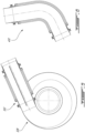
- Fig. 6 presents yet another embodiment where the damper segment 432 is provided in the form of an elbow as opposed to in the form of a straight segment.
- the embodiments described in this document provide non-limiting examples of possible implementations of the present technology.
- a person of ordinary skill in the art will recognize that changes may be made to the embodiments described herein without departing from the scope of the present technology.
- the tubular segment, as the remainder of the pressurized gas pipe can have different cross-sectional shapes such as circular, oval or even square to name some examples.
- Yet further modifications could be implemented by a person of ordinary skill in the art in view of the present disclosure, which modifications would be within the scope of the present technology.
Landscapes
- Engineering & Computer Science (AREA)
- General Engineering & Computer Science (AREA)
- Mechanical Engineering (AREA)
- Chemical & Material Sciences (AREA)
- Combustion & Propulsion (AREA)
- Chemical Kinetics & Catalysis (AREA)
- General Chemical & Material Sciences (AREA)
- Structures Of Non-Positive Displacement Pumps (AREA)
Abstract
Description
- The application relates generally to gas turbine engines and, more particularly, to gas pipe elements thereof.
- Aircraft engines can use piping to convey pressurized gas, such as exhaust gasses or compressed air, from an outlet of a first component to an inlet of a second component. The design of such piping can represent surprisingly complex challenges when taking into consideration factors such as structural resistance, temperature and pressure, limiting weight, and managing dynamic structural effects such as vibrations. There always remains room for improvement.
- In one aspect, there is provided an aircraft engine comprising a combustion engine having an engine intake and an exhaust gas outlet; a gas turbine having a gas turbine intake; an exhaust pipe fluidly connecting the exhaust gas outlet to the gas turbine intake, the exhaust pipe having a length defined between the exhaust gas outlet and the gas turbine intake and an exhaust gas path extending inside the exhaust pipe along the length, the exhaust pipe having a damper segment located along a portion of the length, the damper segment having a proximal end secured to a proximal segment and directed towards the combustion engine relative the internal exhaust gas path, a distal end secured to a distal segment and directed towards the gas turbine intake along the exhaust gas path, a rigid tube at the proximal end, a damper tube extending between the rigid tube and the distal end, the damper tube being made of a metal mesh, a proximal catch connecting a proximal end of the damper tube to the rigid tube, and a distal catch structurally connected between a distal end of the damper tube and the distal segment, the damper tube having an unsupported length extending between the distal catch and the proximal catch, the rigid tube having a liner portion projecting into the distal segment, the liner portion extending internally relative the damper tube.
- In another aspect, there is provided an aircraft engine comprising a combustion engine having an engine intake and an exhaust gas outlet; a compressor having a compressor outlet; an intake pipe fluidly connecting the compressor outlet to the engine intake, the intake pipe having a length defined between the compressor outlet and the engine intake and an intake gas path extending inside the intake pipe along the length, the intake pipe having a damper segment located along a portion of the length, the damper segment having a proximal end secured to a proximal segment and directed towards the compressor outlet relative the internal gas path, a distal end secured to a distal segment and directed towards the engine intake along the gas path, a rigid tube at the proximal end, a damper tube extending between the rigid tube and the distal end, the damper tube being made of a metal mesh, a proximal catch connecting a proximal end of the damper tube to the rigid tube, and a distal catch structurally connected between a distal end of the damper tube and the distal segment, the damper tube having an unsupported length extending between the distal catch and the proximal catch, the rigid tube having a liner portion projecting into the distal segment, the liner portion extending internally relative the damper tube.
- In a further aspect, there is provided a damper segment for assembly between adjacent segments of a pressurized gas pipe relative to a pressurized gas path, the damper segment comprising : a proximal end, a distal end, a rigid tube at the proximal end, a damper tube extending between the rigid tube and the distal end, the damper tube being made of a metal mesh, a proximal catch structurally connecting a proximal end of the damper tube to the rigid tube, and a distal catch structurally connected between a distal end of the damper tube and the distal end, the damper tube having an unsupported length extending between the distal catch and the proximal catch, the rigid tube having a liner portion projecting into the distal segment, the liner portion extending internally relative the damper tube.
- Reference is now made to the accompanying figures in which:
-
Fig. 1 is a schematic cross-sectional view of a gas turbine engine; -
Fig. 2 is a cross-sectional view of a damper segment in accordance with a first embodiment; -
Fig. 3 is a cross-sectional view of a damper segment in accordance with a second embodiment; -
Fig. 4 is a cross-sectional view of a damper segment in accordance with a third embodiment; -
Fig. 5 is a cross-sectional view of a damper segment in accordance with a fourth embodiment; -
Fig. 6 is a cross-sectional view of a damper segment in accordance with a fifth embodiment. -
Fig. 1 illustrates an aircraft gas turbine engine 10 of a type preferably provided for use in subsonic flight, generally comprising acombustion engine 12 in which compressed air is mixed with fuel and ignited delivering mechanical power and exhaust gasses. The exhaust gasses are collected from anexhaust gas outlet 15 of thecombustion engine 12 and directed to anintake 16 of agas turbine 14 via anexhaust pipe 22. Theexhaust pipe 22 can be said to define an exhaust gas path extending inside it along its length. Thegas turbine 14 can convert energy in the form of heat, pressure and/or velocity of the exhaust gasses into angular velocity of a rotor, and the rotor can be used to direct power to one or more other device, such as acompressor 18, a propulsor 20 (e.g. propeller, fan), and/or an electric machine acting as a generator (not shown). The transfer of power can be direct, or via a clutch and/or a gearbox. Thegas turbine 14 is optional. - In this embodiment, a
compressor 18 is provided. Thecompressor 18 can be a centrifugal compressor for instance, and be used to boost the pressure of air from the environment in order to feed higher pressure air to theintake 19 of thecombustion engine 12. More specifically, compressed air can be collected from thecompressor 18 by anintake pipe 25, via ascroll 28 for instance, and fed to theintake 19 of thecombustion engine 12. Theintake pipe 25 can be said to define an intake gas path extending inside it along its length. Thecompressor 18 can be powered by thegas turbine 14, by thecombustion engine 12, and/or by an auxiliary electric engine, to name some examples. Thecompressor 18 is optional. - In the illustrated embodiment, the
combustion engine 12 can have one or more combustion engine units such as piston engine units, and/or Wankel engine units for instance. The compressed air conveyed along the intake path can be distributed to a plurality of the engine units via anintake manifold 21 which can connect theintake pipe 25 to individual engine units. The exhaust gasses can be collected from a plurality of sources associated to corresponding engine units via anexhaust manifold 24 which connects theexhaust pipe 22 to individual engine units. Theintake pipe 19 can convey a linear flow of compressed air whereas thecompressor 18 can be configured for outputting a circumferential flow of compressed air, and theintake pipe 25 can be connected tangentially to the compressor outlet. A device commonly referred to as ascroll 28 can be provided to provide the radial to tangential transition. Theexhaust pipe 22 can convey a linear flow of exhaust gasses, whereas thegas turbine 14 can be configured for receiving an annular stream of exhaust gasses. Agas turbine intake 16 can be provided for connecting theexhaust conduit 22 to thegas turbine 14. Thegas turbine intake 16 can be configured for receiving the linear flow of exhaust gasses from theexhaust pipe 22, distributing it circumferentially, re-orienting its velocity from a circumferential to an axial orientation, and feeding it as an axially-oriented annular stream to thegas turbine 14. In an alternate embodiment, thegas turbine 14 can be centrifugal toaxial gas turbine 14 and have a radially oriented inlet and an axially oriented outlet. - Either one of the
exhaust pipe 22 and theintake pipe 19 can be referred to as a pressurized gas pipe. Either one, or both pressurized gas pipes can be straight, continuously curved, or made of straight sections interconnected via one or more elbows, to name some examples. The pressurized gas pipes can be said to have a length, and to defining a gas path extending inside along the length. Either one, or both pressurized gas pipes can have adamper segment 32 located along a portion of the length. A first example of adamper segment 32 is presented in greater detail inFig. 2 . - In this example, the
damper segment 32 is, like the remainder of the pressurized gas pipe, generally tubular in shape. By convention in the context of this specification, the expression "proximal" will be used to refer to the leading side, i.e. direction of incoming gas, whereas the expression "distal" will be used to refer to the trailing side, i.e. the direction of gas evacuation. Accordingly, thedamper segment 32 can be said to have aproximal end 34 connected to aproximal segment 36 of the pressurizedgas pipe 38, and adistal end 40 connected to adistal segment 42 of the pressurizedgas pipe 38. In this embodiment, both theproximal segment 36 and thedistal segment 42 are rigid. Thedamper segment 32 has arigid tube 44 and adamper tube 46. More specifically a first portion of therigid tube 44 which will be referred to herein as theconnector portion 48 is secured to theproximal segment 36, and a second portion of therigid tube 44 referred to herein as theliner portion 50 projects from theconnector portion 48 in the direction of gas flow and reaches thedistal segment 42. More specifically, theliner portion 50 penetrates into thedistal segment 42 to a certain extent, in this embodiment. Thedamper tube 46 extends around theliner portion 50 along a portion of the length of theliner portion 50. - The
damper tube 46 also has a proximal end and a distal end. The proximal end of thedamper tube 46 is supported by aproximal catch 52, which connects the proximal end of thedamper tube 46 to therigid tube 44, and more specifically to theconnector portion 48 of therigid tube 44. The distal end of thedamper tube 46 is supported by adistal catch 54. Thedistal catch 54 is structurally connected between a distal end of thedamper tube 46 and thedistal segment 42. More specifically, in this embodiment, thedistal catch 54 forms part of a rigid component which is secured to thedistal segment 42. Thedamper tube 46 has anunsupported length 56 extending between thedistal catch 54 and theproximal catch 52. In other words, anannular gap 58 is provided between theunsupported length 56 of thedamper tube 46 and theliner portion 50 of therigid tube 44. Thisgap 58 provides room for theunsupported length 56 of thedamper tube 46 to move and oscillate into. - The
damper tube 46 is made of a metal mesh. The metal mesh can have a plurality of ply. The metal mesh can be tightly braided. Thedamper tube 46 can be heat-resistant, pressure-resistant and air tight. Thedamper tube 46 can be supple. Theliner portion 50 of therigid tube 44 can act as the delimitation of the gas path, while being structurally disconnected from thedistal segment 42 at thedistal end 40, whereas thedamper tube 46 can form a portion of the structural connection between theproximal segment 36 and thedistal segment 42. Accordingly, thedamper segment 46 can allow to accommodate some degree of relative movement between theproximal segment 36 and thedistal segment 42. More specifically, upon relative lengthwise displacement, theliner portion 50 of therigid tube 44 can slide deeper into or retract from thedistal segment 42, and thedamper tube 46 can compress or expand. Upon transversal displacement, the distal end of theliner portion 50 can, to a certain extent, move transversally within thedistal segment 42. More specifically, agap 60 can be provided between the distal end of theliner portion 50 and the proximal end of thedistal segment 42, and transversal movement can close the gap on one side while opening the gap on the other side, for instance. Thegap 60 can be permanent, or temporary. For instance, in some engine conditions (e.g. max power), thegap 60 can be designed to close whereas it can be designed to open in some other engine conditions (e.g. idle or off). Upon transversal relative movement, the unsupported length of thedamper tube 46 can bend to a certain, for instance. Moreover, thedamper tube 46 can be designed to provide a damping dynamic behavior. Indeed, if one of theproximal segment 36 and thedistal segment 42, or both theproximal segment 36 and thedistal segment 42 vibrate, theunsupported length 56 of thedamper tube 46 can serve to absorb some or all of the vibrational energy in a manner to prevent or limit the transmission of vibrational energy from theproximal segment 36 to thedistal segment 42 or vice versa. - There are different ways by which the
proximal end 34 and thedistal end 40 of thedamper segment 32 can be secured to the corresponding one of theproximal segment 36 and thedistal segment 42. In the example embodiment presented inFig. 2 , both theproximal end 34 and thedistal end 40 are secured to the corresponding one of theproximal segment 36 and thedistal segment 42 with corresponding V-Band clamps 62, 64. The V-Band clamps 62, 64 can be embodied as generally annular components having a radially-inwardly facing channel which is generally shaped as a V. On the other hand, both components to be secured can be provided with a corresponding outwardly sloping flange, and prior to assembly, the components can be positioned in a manner for the opposite faces of the flanges to become engaged into contact with one another. An opening can be provided around the circumference of the V-Band clamp and a fastener such as a bolt can be selectively positioned across the opening and tightened in a manner to close the opening, thereby engaging faces of the V-shaped channel with corresponding sloping faces of the flanges, wedging the flanges against one another, with the V-shaped channel acting as a retainer. V-Band clamps can be an interesting choice to connect thedamper segment 32 to one, or bothadjacent segments - Turning to
Fig. 3 , an embodiment of adamper segment 132 having a bolt and flange type connection, i.e. a connection in the form of a boltedflange arrangement Fig. 4 , an embodiment of adamper segment 232 having a weldedconnection - Returning to
Fig. 3 , an embodiment of adamper segment 132 is presented wherein the distal catch is indirectly structurally connected between the distal end of the damper tube and the distal segment. More specifically, thedistal catch 154 is structurally connected to the distal segment via an undulatedflexible tubing 176, sometimes referred to in the art as a "bellows". The undulatedflexible tubing 176 can be designed to provide further accommodation of relative displacements between the proximal segment and the distal segment, for instance. In an alternate embodiment, an undulated flexible tubing can be provided between the proximal catch and the proximal end of the damper tube. It will be noted in this embodiment that the undulated flexible tubing is provided as a portion of the structural path between the proximal segment and the distal segment, and is thus provided "in series", so to speak, with the damper tube, and not "in parallel" with the damper tube. -
Fig. 5 presents yet another embodiment of adamper segment 332. In this embodiment, thedamper segment 332 is secured to a tangential outlet of acompressor scroll 328. Accordingly, in this embodiment, the proximal segment of the pressurized gas pipe is embodied as a tubular portion of thecompressor scroll 328 itself.Fig. 5 is thus different from the embodiments presented inFigs. 2 ,3 and 4 and where the damper segment is located at an intermediary location of the pressurized gas pipe as opposed to at or near an end of the pressurized gas pipe. -
Fig. 6 presents yet another embodiment where thedamper segment 432 is provided in the form of an elbow as opposed to in the form of a straight segment. - The embodiments described in this document provide non-limiting examples of possible implementations of the present technology. Upon review of the present disclosure, a person of ordinary skill in the art will recognize that changes may be made to the embodiments described herein without departing from the scope of the present technology. For example, the tubular segment, as the remainder of the pressurized gas pipe, can have different cross-sectional shapes such as circular, oval or even square to name some examples. Yet further modifications could be implemented by a person of ordinary skill in the art in view of the present disclosure, which modifications would be within the scope of the present technology.
Claims (15)
- An aircraft engine comprising a combustion engine having an engine intake and an exhaust gas outlet; a gas turbine having a gas turbine intake; an exhaust pipe fluidly connecting the exhaust gas outlet to the gas turbine intake, the exhaust pipe having a length defined between the exhaust gas outlet and the gas turbine intake and an exhaust gas path extending inside the exhaust pipe along the length, the exhaust pipe having a damper segment located along a portion of the length, the damper segment havinga proximal end secured to a proximal segment and directed towards the combustion engine relative the exhaust gas path,a distal end secured to a distal segment and directed towards the gas turbine intake along the exhaust gas path,a rigid tube at the proximal end,a damper tube extending between the rigid tube and the distal end, the damper tube being made of a metal mesh,a proximal catch connecting a proximal end of the damper tube to the rigid tube, anda distal catch structurally connected between a distal end of the damper tube and the distal segment, the damper tube having an unsupported length extending between the distal catch and the proximal catch,the rigid tube having a liner portion projecting into the distal segment, the liner portion extending internally relative the damper tube.
- An aircraft engine comprising a combustion engine having an engine intake and an exhaust gas outlet; a compressor having a compressor outlet; an intake pipe fluidly connecting the compressor outlet to the engine intake, the intake pipe having a length defined between the compressor outlet and the engine intake and an intake gas path extending inside the intake pipe along the length, the intake pipe having a damper segment located along a portion of the length, the damper segment havinga proximal end secured to a proximal segment and directed towards the compressor outlet relative the intake gas path,a distal end secured to a distal segment and directed towards the engine intake along the intake gas path,a rigid tube at the proximal end,a damper tube extending between the rigid tube and the distal end, the damper tube being made of a metal mesh,a proximal catch connecting a proximal end of the damper tube to the rigid tube, anda distal catch structurally connected between a distal end of the damper tube and the distal segment, the damper tube having an unsupported length extending between the distal catch and the proximal catch,the rigid tube having a liner portion projecting into the distal segment, the liner portion extending internally relative the damper tube.
- The aircraft engine of claim 1 or 2 further comprising an annular gap between a distal end of the liner portion and the distal segment.
- The aircraft engine of any preceding claim wherein the metal mesh is a braided steel mesh having at least one ply.
- The aircraft engine of any preceding claim wherein at least one of the proximal end and the distal end is secured to a corresponding one of the proximal segment and the distal segment via a V-Band clamp.
- The aircraft engine of any preceding claim wherein at least one of the proximal end and the distal end is secured to a corresponding one of the proximal segment and the distal segment via a bolted flange arrangement.
- The aircraft engine of any preceding claim wherein the damper segment forms an elbow in the exhaust pipe or the intake pipe.
- A damper segment for assembly between adjacent segments of a pressurized gas pipe relative to a pressurized gas path, the damper segment comprising :a proximal end,a distal end,a rigid tube at the proximal end,a damper tube extending between the rigid tube and the distal end, the damper tube being made of a metal mesh,a proximal catch structurally connecting a proximal end of the damper tube to the rigid tube, anda distal catch structurally connected between a distal end of the damper tube and the distal end, the damper tube having an unsupported length extending between the distal catch and the proximal catch,the rigid tube having a liner portion projecting into the distal end, the liner portion extending internally relative the damper tube.
- The damper segment of claim 8 further comprising an annular gap between the unsupported length of the damper tube and the liner portion of the rigid tube.
- The damper segment of claim 8 or 9 wherein the metal mesh is a braided steel mesh having at least one ply.
- The damper segment of any of claims 8 to 10 wherein at least one of the proximal end and of the distal end has an outwardly sloping flange configured for use with a V-Band clamp.
- The damper segment of any of claims 8 to 11 wherein at least one of the proximal end and of the distal end has an outwardly projecting flange forming a component of a bolted flange arrangement.
- The damper segment of any of claims 8 to 12 wherein the damper segment forms an elbow.
- The damper segment of any of claims 8 to 13 wherein the damper segment has a circular cross-sectional shape.
- The damper segment of any of claims 8 to 14 further comprising a bellows structurally connected between the distal catch and the distal end.
Applications Claiming Priority (1)
| Application Number | Priority Date | Filing Date | Title |
|---|---|---|---|
| US17/858,293 US12188364B2 (en) | 2022-07-06 | 2022-07-06 | Damper segment for pressurized gas pipe of aircraft engine |
Publications (1)
| Publication Number | Publication Date |
|---|---|
| EP4303404A1 true EP4303404A1 (en) | 2024-01-10 |
Family
ID=87157874
Family Applications (1)
| Application Number | Title | Priority Date | Filing Date |
|---|---|---|---|
| EP23184008.3A Pending EP4303404A1 (en) | 2022-07-06 | 2023-07-06 | Damper segment for pressurized gas pipe of aircraft engine |
Country Status (3)
| Country | Link |
|---|---|
| US (1) | US12188364B2 (en) |
| EP (1) | EP4303404A1 (en) |
| CA (1) | CA3204000A1 (en) |
Citations (4)
| Publication number | Priority date | Publication date | Assignee | Title |
|---|---|---|---|---|
| US2470989A (en) * | 1943-12-16 | 1949-05-24 | Chicago Metal Hose Corp | Flexible connector |
| EP0989289A1 (en) * | 1998-09-25 | 2000-03-29 | FLEXIDER S.p.A. | Flexible vibration-decoupling joint, in particular for exhaust pipes in motor vehicles |
| EP1026375B1 (en) * | 1999-02-05 | 2005-06-01 | Witzenmann GmbH | Pipe member for exhaust conduits in motor vehicles |
| US20200182261A1 (en) * | 2017-11-24 | 2020-06-11 | Mitsubishi Heavy Industries Engine & Turbocharger, Ltd. | Vibration suppressing method for supercharger, and supercharger |
Family Cites Families (18)
| Publication number | Priority date | Publication date | Assignee | Title |
|---|---|---|---|---|
| US2385366A (en) | 1938-04-19 | 1945-09-25 | Jarvis C Marble | Power plant for aircraft |
| GB571022A (en) | 1942-06-11 | 1945-08-02 | Chicago Metal Hose Corp | Improvements relating to flexible pipe connections or conduits |
| GB688111A (en) | 1945-05-23 | 1953-02-25 | Miles Lowell Edwards | Improvements in or relating to liquid and gas separating devices |
| US2801043A (en) | 1954-08-24 | 1957-07-30 | Thompson Prod Inc | Turbine supercharger |
| US3396906A (en) | 1968-02-06 | 1968-08-13 | Trane Co | Pump housing seal arrangement |
| US4996839A (en) | 1987-02-24 | 1991-03-05 | Teledyne Industries, Inc. | Turbocharged compound cycle ducted fan engine system |
| US5145215A (en) | 1991-04-26 | 1992-09-08 | Senior Engineering Investments, B.V. | Flexible coupler apparatus |
| DE19936170A1 (en) | 1999-07-31 | 2001-02-01 | Rolls Royce Deutschland | Cooling air pipe for aircraft gas turbine engine consists of double-walled three-part pipe with inner tube for cooling air flow |
| US7074009B2 (en) | 2000-06-07 | 2006-07-11 | Borgwarner, Inc. | Casing assembly for the turbine of an exhaust turbochanger |
| US6783321B2 (en) | 2002-11-06 | 2004-08-31 | General Electric Company | Diffusing coupling cover for axially joined turbines |
| US7147433B2 (en) | 2003-11-19 | 2006-12-12 | Honeywell International, Inc. | Profiled blades for turbocharger turbines, compressors, and the like |
| JP5433560B2 (en) | 2010-12-27 | 2014-03-05 | 三菱重工業株式会社 | Turbine scroll part structure |
| JP5984446B2 (en) | 2012-03-23 | 2016-09-06 | 三菱重工業株式会社 | Turbine housing assembly and method of manufacturing turbine housing assembly |
| JP5975698B2 (en) | 2012-03-30 | 2016-08-23 | 大豊工業株式会社 | Turbocharger |
| JP5880463B2 (en) | 2013-01-29 | 2016-03-09 | 株式会社豊田自動織機 | Turbocharger |
| US10030581B2 (en) | 2016-02-24 | 2018-07-24 | Pratt & Whitney Canada Corp. | Air intake with scroll portion and strutted portion for gas turbine engine |
| GB2552686B (en) * | 2016-08-03 | 2020-04-29 | Rolls Royce Plc | Gimbal expansion joint |
| CN107725195A (en) | 2017-11-23 | 2018-02-23 | 上海泛智能源装备有限公司 | A kind of air inlet volute and gas turbine |
-
2022
- 2022-07-06 US US17/858,293 patent/US12188364B2/en active Active
-
2023
- 2023-06-19 CA CA3204000A patent/CA3204000A1/en active Pending
- 2023-07-06 EP EP23184008.3A patent/EP4303404A1/en active Pending
Patent Citations (4)
| Publication number | Priority date | Publication date | Assignee | Title |
|---|---|---|---|---|
| US2470989A (en) * | 1943-12-16 | 1949-05-24 | Chicago Metal Hose Corp | Flexible connector |
| EP0989289A1 (en) * | 1998-09-25 | 2000-03-29 | FLEXIDER S.p.A. | Flexible vibration-decoupling joint, in particular for exhaust pipes in motor vehicles |
| EP1026375B1 (en) * | 1999-02-05 | 2005-06-01 | Witzenmann GmbH | Pipe member for exhaust conduits in motor vehicles |
| US20200182261A1 (en) * | 2017-11-24 | 2020-06-11 | Mitsubishi Heavy Industries Engine & Turbocharger, Ltd. | Vibration suppressing method for supercharger, and supercharger |
Also Published As
| Publication number | Publication date |
|---|---|
| US20240011415A1 (en) | 2024-01-11 |
| CA3204000A1 (en) | 2024-01-06 |
| US12188364B2 (en) | 2025-01-07 |
Similar Documents
| Publication | Publication Date | Title |
|---|---|---|
| CN105277023B (en) | Method and system for radial tubular heat exchanger | |
| JP4906924B2 (en) | Ring seal for gas sealing and vibration damping | |
| US12264595B2 (en) | Turbine support case having axial spokes | |
| EP4296472B1 (en) | Aircraft engine, gas turbine intake therefore, and method of guiding exhaust gasses | |
| US12188364B2 (en) | Damper segment for pressurized gas pipe of aircraft engine | |
| US11346249B2 (en) | Gas turbine engine with feed pipe for bearing housing | |
| US20250052187A1 (en) | Turbocharger | |
| US5016436A (en) | Interturbine duct | |
| EP4400695A1 (en) | Gas turbine intake for aircraft engine and method of inspection thereof | |
| WO2013089158A1 (en) | Turbocharger exhaust entrance casing | |
| US11391179B2 (en) | Gas turbine engine with bearing support structure | |
| EP4311943B1 (en) | Diffuser and associated compressor section of aircraft engine | |
| US12486788B1 (en) | Turbine support case supported by stopping ribs | |
| US12595750B1 (en) | Turbine support case with axial spokes and brackets | |
| EP4733552A1 (en) | Aircraft engine having a scroll case and a turbine support case secured together | |
| US12631129B2 (en) | Aircraft engine having scroll case with flange connection | |
| EP4733547A1 (en) | Aircraft engine having scroll case with flange connection | |
| US11851202B1 (en) | Aircraft engine, gas turbine intake therefore, and method of guiding exhaust gasses | |
| CN114302848B (en) | Air intake pipe of aircraft turbine engine nacelle | |
| US20260049618A1 (en) | Recovered-cycle aircraft turbine engine | |
| WO2025096675A1 (en) | Turbocharger assembly | |
| CA3288250A1 (en) | Turbine support case with axial spokes and brackets | |
| CN107110005A (en) | The method that pressurizing air tracheae and management thermal expansion are supported using wear-resisting external member | |
| US20140182308A1 (en) | Gas turbine engine with v-band clamp connection for collector box |
Legal Events
| Date | Code | Title | Description |
|---|---|---|---|
| PUAI | Public reference made under article 153(3) epc to a published international application that has entered the european phase |
Free format text: ORIGINAL CODE: 0009012 |
|
| STAA | Information on the status of an ep patent application or granted ep patent |
Free format text: STATUS: THE APPLICATION HAS BEEN PUBLISHED |
|
| AK | Designated contracting states |
Kind code of ref document: A1 Designated state(s): AL AT BE BG CH CY CZ DE DK EE ES FI FR GB GR HR HU IE IS IT LI LT LU LV MC ME MK MT NL NO PL PT RO RS SE SI SK SM TR |
|
| STAA | Information on the status of an ep patent application or granted ep patent |
Free format text: STATUS: REQUEST FOR EXAMINATION WAS MADE |
|
| 17P | Request for examination filed |
Effective date: 20240710 |
|
| RBV | Designated contracting states (corrected) |
Designated state(s): AL AT BE BG CH CY CZ DE DK EE ES FI FR GB GR HR HU IE IS IT LI LT LU LV MC ME MK MT NL NO PL PT RO RS SE SI SK SM TR |
|
| STAA | Information on the status of an ep patent application or granted ep patent |
Free format text: STATUS: EXAMINATION IS IN PROGRESS |
|
| 17Q | First examination report despatched |
Effective date: 20241108 |