EP4303399A2 - Mittel und verfahren für verbesserte genauigkeit einer drehenden vermessung - Google Patents
Mittel und verfahren für verbesserte genauigkeit einer drehenden vermessung Download PDFInfo
- Publication number
- EP4303399A2 EP4303399A2 EP23209897.0A EP23209897A EP4303399A2 EP 4303399 A2 EP4303399 A2 EP 4303399A2 EP 23209897 A EP23209897 A EP 23209897A EP 4303399 A2 EP4303399 A2 EP 4303399A2
- Authority
- EP
- European Patent Office
- Prior art keywords
- sensor array
- survey
- measurements
- survey measurements
- drilling
- Prior art date
- Legal status (The legal status is an assumption and is not a legal conclusion. Google has not performed a legal analysis and makes no representation as to the accuracy of the status listed.)
- Pending
Links
- 238000000034 method Methods 0.000 title claims description 35
- 238000005259 measurement Methods 0.000 claims abstract description 157
- 238000005553 drilling Methods 0.000 claims abstract description 113
- 239000013598 vector Substances 0.000 claims description 12
- 238000012805 post-processing Methods 0.000 claims description 7
- 239000012530 fluid Substances 0.000 description 7
- 230000008569 process Effects 0.000 description 6
- 230000005484 gravity Effects 0.000 description 5
- 230000003993 interaction Effects 0.000 description 4
- 230000032683 aging Effects 0.000 description 3
- 230000015572 biosynthetic process Effects 0.000 description 3
- 238000012937 correction Methods 0.000 description 3
- 230000004927 fusion Effects 0.000 description 3
- 230000004048 modification Effects 0.000 description 3
- 238000012986 modification Methods 0.000 description 3
- 230000000737 periodic effect Effects 0.000 description 3
- 238000012545 processing Methods 0.000 description 3
- 238000003878 thermal aging Methods 0.000 description 3
- 238000005382 thermal cycling Methods 0.000 description 3
- 238000004364 calculation method Methods 0.000 description 2
- 230000008859 change Effects 0.000 description 2
- 238000012935 Averaging Methods 0.000 description 1
- 230000005355 Hall effect Effects 0.000 description 1
- 230000001133 acceleration Effects 0.000 description 1
- 230000005540 biological transmission Effects 0.000 description 1
- 230000015556 catabolic process Effects 0.000 description 1
- 238000005520 cutting process Methods 0.000 description 1
- 238000006731 degradation reaction Methods 0.000 description 1
- 238000013461 design Methods 0.000 description 1
- 230000002708 enhancing effect Effects 0.000 description 1
- 238000001914 filtration Methods 0.000 description 1
- 230000004907 flux Effects 0.000 description 1
- 230000002706 hydrostatic effect Effects 0.000 description 1
- 230000007246 mechanism Effects 0.000 description 1
- 239000010453 quartz Substances 0.000 description 1
- 238000005070 sampling Methods 0.000 description 1
- 230000035945 sensitivity Effects 0.000 description 1
- 230000001953 sensory effect Effects 0.000 description 1
- VYPSYNLAJGMNEJ-UHFFFAOYSA-N silicon dioxide Inorganic materials O=[Si]=O VYPSYNLAJGMNEJ-UHFFFAOYSA-N 0.000 description 1
- 230000003068 static effect Effects 0.000 description 1
- 239000000126 substance Substances 0.000 description 1
Images


Classifications
-
- E—FIXED CONSTRUCTIONS
- E21—EARTH OR ROCK DRILLING; MINING
- E21B—EARTH OR ROCK DRILLING; OBTAINING OIL, GAS, WATER, SOLUBLE OR MELTABLE MATERIALS OR A SLURRY OF MINERALS FROM WELLS
- E21B47/00—Survey of boreholes or wells
- E21B47/02—Determining slope or direction
- E21B47/024—Determining slope or direction of devices in the borehole
-
- E—FIXED CONSTRUCTIONS
- E21—EARTH OR ROCK DRILLING; MINING
- E21B—EARTH OR ROCK DRILLING; OBTAINING OIL, GAS, WATER, SOLUBLE OR MELTABLE MATERIALS OR A SLURRY OF MINERALS FROM WELLS
- E21B7/00—Special methods or apparatus for drilling
- E21B7/04—Directional drilling
- E21B7/06—Deflecting the direction of boreholes
-
- E—FIXED CONSTRUCTIONS
- E21—EARTH OR ROCK DRILLING; MINING
- E21B—EARTH OR ROCK DRILLING; OBTAINING OIL, GAS, WATER, SOLUBLE OR MELTABLE MATERIALS OR A SLURRY OF MINERALS FROM WELLS
- E21B44/00—Automatic control systems specially adapted for drilling operations, i.e. self-operating systems which function to carry out or modify a drilling operation without intervention of a human operator, e.g. computer-controlled drilling systems; Systems specially adapted for monitoring a plurality of drilling variables or conditions
- E21B44/005—Below-ground automatic control systems
-
- E—FIXED CONSTRUCTIONS
- E21—EARTH OR ROCK DRILLING; MINING
- E21B—EARTH OR ROCK DRILLING; OBTAINING OIL, GAS, WATER, SOLUBLE OR MELTABLE MATERIALS OR A SLURRY OF MINERALS FROM WELLS
- E21B47/00—Survey of boreholes or wells
- E21B47/02—Determining slope or direction
- E21B47/022—Determining slope or direction of the borehole, e.g. using geomagnetism
-
- E—FIXED CONSTRUCTIONS
- E21—EARTH OR ROCK DRILLING; MINING
- E21B—EARTH OR ROCK DRILLING; OBTAINING OIL, GAS, WATER, SOLUBLE OR MELTABLE MATERIALS OR A SLURRY OF MINERALS FROM WELLS
- E21B7/00—Special methods or apparatus for drilling
- E21B7/04—Directional drilling
- E21B7/06—Deflecting the direction of boreholes
- E21B7/064—Deflecting the direction of boreholes specially adapted drill bits therefor
-
- G—PHYSICS
- G01—MEASURING; TESTING
- G01V—GEOPHYSICS; GRAVITATIONAL MEASUREMENTS; DETECTING MASSES OR OBJECTS; TAGS
- G01V11/00—Prospecting or detecting by methods combining techniques covered by two or more of main groups G01V1/00 - G01V9/00
- G01V11/002—Details, e.g. power supply systems for logging instruments, transmitting or recording data, specially adapted for well logging, also if the prospecting method is irrelevant
-
- G—PHYSICS
- G01—MEASURING; TESTING
- G01V—GEOPHYSICS; GRAVITATIONAL MEASUREMENTS; DETECTING MASSES OR OBJECTS; TAGS
- G01V13/00—Manufacturing, calibrating, cleaning, or repairing instruments or devices covered by groups G01V1/00 – G01V11/00
-
- G—PHYSICS
- G01—MEASURING; TESTING
- G01V—GEOPHYSICS; GRAVITATIONAL MEASUREMENTS; DETECTING MASSES OR OBJECTS; TAGS
- G01V3/00—Electric or magnetic prospecting or detecting; Measuring magnetic field characteristics of the earth, e.g. declination, deviation
- G01V3/18—Electric or magnetic prospecting or detecting; Measuring magnetic field characteristics of the earth, e.g. declination, deviation specially adapted for well-logging
- G01V3/26—Electric or magnetic prospecting or detecting; Measuring magnetic field characteristics of the earth, e.g. declination, deviation specially adapted for well-logging operating with magnetic or electric fields produced or modified either by the surrounding earth formation or by the detecting device
-
- E—FIXED CONSTRUCTIONS
- E21—EARTH OR ROCK DRILLING; MINING
- E21B—EARTH OR ROCK DRILLING; OBTAINING OIL, GAS, WATER, SOLUBLE OR MELTABLE MATERIALS OR A SLURRY OF MINERALS FROM WELLS
- E21B47/00—Survey of boreholes or wells
- E21B47/09—Locating or determining the position of objects in boreholes or wells, e.g. the position of an extending arm; Identifying the free or blocked portions of pipes
-
- G—PHYSICS
- G01—MEASURING; TESTING
- G01C—MEASURING DISTANCES, LEVELS OR BEARINGS; SURVEYING; NAVIGATION; GYROSCOPIC INSTRUMENTS; PHOTOGRAMMETRY OR VIDEOGRAMMETRY
- G01C19/00—Gyroscopes; Turn-sensitive devices using vibrating masses; Turn-sensitive devices without moving masses; Measuring angular rate using gyroscopic effects
- G01C19/02—Rotary gyroscopes
Definitions
- the present disclosure relates generally to rotating survey measurements during drilling of a wellbore, and more specifically to providing measurements of a drilling tool or measurement while drilling (MWD) tool such as revolutions per minute (RPM), azimuth, magnetic and/or gravity tool face, and gravity inclination of a bottom hole assembly (BHA) with improved accuracy.
- MWD measurement while drilling
- RPM revolutions per minute
- azimuth azimuth
- magnetic and/or gravity tool face magnetic and/or gravity tool face
- BHA bottom hole assembly
- the rotating survey measurements provide a steering system of the BHA with a location and heading direction of a drill bit within the well.
- the high bandwidth sensors may experience non-repeatable errors, random scale errors, and bias drift errors due to thermal cycling and aging experienced by the sensors, which may result in inaccurate measurements of the location of the drill bit.
- the high bandwidth sensors may generally produce reliable rotating survey measurements in harsh environments experienced during drilling at a position along a drill string near a drill bit.
- low bandwidth sensors with greater accuracy may be applied along a drill string to replace the high bandwidth sensors.
- the low bandwidth sensors may be applied along the string in a position remote from the high bandwidth sensors. While the low bandwidth sensors have a greater accuracy, the low bandwidth sensors may be susceptible to errors resulting from the harsh environments experienced during drilling.
- any use of any form of the terms “connect,” “engage,” “couple,” “attach,” or any other term describing an interaction between elements is not meant to limit the interaction to direct interaction between the elements and may also include indirect interaction between the elements described.
- the terms “including” and “comprising” are used in an open-ended fashion, and thus should be interpreted to mean “including, but not limited to”. Unless otherwise indicated, as used throughout this document, "or” does not require mutual exclusivity.
- the present disclosure relates to enhancing rotating survey accuracy for a downhole surveying tool. More particularly, the present disclosure relates to calibrating a high bandwidth sensor using data gathered from a low bandwidth sensor to increase surveying accuracy while drilling.
- the presently disclosed embodiments may be used in horizontal, vertical, deviated, or otherwise nonlinear wellbores in any type of subterranean formation. Embodiments may include sensors of varying ranges and types to provide an accurate position of a drill bit while drilling a wellbore.
- the drilling system 100 includes a derrick 102 that is buttressed by a derrick floor 104.
- the derrick floor 104 supports a rotary table 106 that is driven during drilling at a desired rotational speed, for example, via a chain drive system through operation of a prime mover (not shown).
- the rotary table 106 provides the rotational force to a drill string 108 within a wellbore 109.
- the drill string 108 is coupled to a bottom hole assembly (BHA) 110.
- the BHA 110 includes a high bandwidth sensor array 112, a low bandwidth sensor array 114, a steering system 116, and a drill bit 118.
- the drilling system 100 also includes a drilling fluid reservoir 120.
- the drilling fluid reservoir 120 provides drilling fluid (e.g., drilling mud) through the drill string 108 to the BHA 110.
- the drilling fluid may continuously circulate through drill string 108, to an end 122 of the wellbore 109, and back to a surface 124. Further, the drilling fluid provides hydrostatic pressure that prevents formation fluids from entering into the wellbore 108, keeps the drill bit cool and clean, and carries out drill cuttings during a drilling process.
- a mud motor is present in the BHA 110, the flow of drilling fluid through the drill string 108 generates power at the BHA 110.
- the power generated at the BHA 110 provides power to the high bandwidth sensor array 112, the low bandwidth sensor array 114, and the steering system 116.
- the steering system 116 provides steering control to the drill bit 118.
- a target path 126 is programmed into the steering system 116 prior to commencing a drilling operation of the wellbore 109.
- the target path 126 may be embodied as instructions stored in a memory of the steering system 116, and a processor of the steering system 116 executes the instructions to control the direction of drilling by the drill bit 118.
- the high bandwidth sensor array 112 and the low bandwidth sensor array 114 provide survey data to the steering system 116 during the drilling operation that provides an indication of a location of the drill bit 118 during the drilling process.
- the steering system 116 uses this data to maintain the drill bit 118 on the target path 126 or to realign the drill bit 118 to the target path when the steering system 118 receives an indication that the drill bit 118 has drifted from the target path 126.
- the high bandwidth sensor array 112 may include one or more sensors, as discussed in further detail below with reference to FIG. 3 .
- the one or more sensors may include accelerometers, gyroscopes, and magnetometers that, when used in varying combinations, provide an indication of the location of the drill bit 118.
- the low bandwidth sensor array 114 may include similar sensors with heightened sensitivities, for example. It may be appreciated that the low bandwidth sensor array 114 may generally include a smaller dynamic range than the high bandwidth sensor array 112. Having the smaller dynamic range may make the low bandwidth sensor array 114 better suited for lower bandwidth measurements than the high bandwidth sensor array 112.
- the high bandwidth sensor array 112 may have a lower base accuracy than the low bandwidth sensor array 114. Accordingly, measurements from the low bandwidth sensor array 112 may be used by the steering system 116 to correct the less accurate measurements of the high bandwidth sensor array 114. Further, as the low bandwidth sensor array 114 is prone to errors resulting from the hostile drilling environment, measurements from the low bandwidth sensor array 114 may only be used in correcting the measurements of the high bandwidth sensor array 112 when certain drilling criteria are established.
- the measurements are collected by the low bandwidth sensor array 114 and used to correct the measurements of the high bandwidth sensor array 112 when drilling is stopped (e.g., when new sections of the drill string 108 are installed), when RPM of the drill string 108 are constant, and/or when vibration of the drill string 108 is below a threshold.
- the high bandwidth sensor array 112 may continue taking measurements under drilling conditions without losing accuracy as a result of the hostile drilling environment.
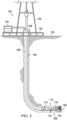
- FIG. 2 is a schematic view of the drilling system 100 after extending the wellbore 109 in a horizontal direction to generate a horizontal portion 200 of the wellbore 109.
- the steering system 116 uses measurements from the high bandwidth sensor array 112 and the low bandwidth sensor array 114 to maintain the drill bit 118 along the target path 126 of the wellbore 109.
- the steering system 116 may continue to dynamically alter the course of the drill bit 118 to maintain the trajectory of the target path 126 based on the survey measurements of the high bandwidth sensor array 112 and the low bandwidth sensor array 114.
- the high bandwidth sensor array 112 and the low bandwidth sensor array 114 While the measurements from the high bandwidth sensor array 112 and the low bandwidth sensor array 114 are continuously provided to the steering system 116 to steer the drill bit 118, the high bandwidth sensor array 112 and the low bandwidth sensor array 114 also provide the measurements to the surface 124 periodically. Because bandwidth to send data to the surface 124 is limited, the high bandwidth sensor array 112 and the low bandwidth sensor array 114 may provide data to the surface 124 at preset intervals. For example, the high bandwidth sensor array 112 and the low bandwidth sensor array 114 may provide an update to the surface 124 every ten minutes. It may be appreciated that the high bandwidth sensor array 112 and the low bandwidth sensor array 114 may also provide updates more or less frequently depending on parameters set by an operator of the drilling system 100. The periodic updates may be used by the operator to ensure that the steering system 116 is maintaining the target path 126. Further, the periodic updates may be a mechanism for the operator to ensure that the high bandwidth sensor array 112 and the low bandwidth sensor array 114 are both functioning properly.
- the sensor system 300 (i.e., a rotating survey tool) includes the high bandwidth sensor array 112 and the low bandwidth sensory array 114.
- the high bandwidth sensor array 112 includes sensors 302A and 302B.
- the sensors 302A and 302B may be accelerometers, such as quartz hinge accelerometers or microelectromechanical systems (MEMS) accelerometers.
- MEMS microelectromechanical systems
- the sensors 302A and 302B may be gyroscopes (e.g., MEMS bases gyroscopes) or magnetometers (e.g., flux gate, Hall effect, magnetoresistive, or Lorentz force based MEMS devices). Any combination of accelerometers, gyroscopes, and magnetometers is also contemplated as making up the sensors 302A and 302B.
- the high bandwidth sensor array 112 includes a lower base accuracy than the low bandwidth sensor array 114.
- the sensors 302A and 302B of the high bandwidth sensor array 112 may also be prone to errors due to thermal cycling and aging. However, the high bandwidth sensor array 112 is capable of providing measurements under drilling conditions.
- More accurate sensors 304A, 304B, and 304C of the low bandwidth sensor array 114 may be used periodically to calibrate the sensors 302A and 302B of the high bandwidth sensor array 112.
- the sensors 304A, 304B, and 304C may also be a combination of accelerometers, gyroscopes, and magnetometers.
- the low bandwidth sensor array 114 is depicted with the three sensors 304A, 304B, and 304C, and the high bandwidth sensor array 112 is depicted with the two sensors 302A and 302B, any number of sensors may be used in the low bandwidth sensor array 114 and the high bandwidth sensor array 112.
- a space 306 is provided between the high bandwidth sensor array 112 and the low bandwidth sensor array 114.
- a width 308 of the space 306 may be minimized as much as possible such that three-dimensional vectors of all of the sensors 302A, 302B, 304A, 304B, and 304C are substantially the same. That is, the sensors 302A, 302B, 304A, 304B, and 304C, at any given moment, are all providing survey measurements at generally the same location within the wellbore 109 at the same time.
- a length 310 of the sensing system 300 may be less than six feet. In some embodiments, depending on a size and number of the sensors 302A, 302B, 304A, 304B, and 304C, it is contemplated that the length 310 may be slightly larger than six feet.
- the high bandwidth sensor array 112 may operate properly under any drilling environment.
- the high bandwidth sensor array 112 may perform within specified accuracy ranges regardless of the vibration on the drill string 108.
- the low bandwidth sensor array 112 may operate properly when a vibration level on the drill string 108 is sufficiently low.
- the low bandwidth sensor array 112 may perform sufficiently when the average vibration levels experienced by the low bandwidth sensor array 112 are less than a 3 g average vibration in addition to 1 g of gravity.
- the low bandwidth sensor array 112 may generally conduct useful measurements when the RPM of the drill bit 118 is substantially constant, when the average vibration is below the 3 g average vibration threshold, or some combination thereof.
- the term "substantially constant” may mean that the RPM of the drill bit 118 stays within a specified percentage of a base RPM value.
- substantially constant may mean that the RPM of the drill bit 118 does not drift more than 5% from the base RPM value.
- the 5% threshold is used as an example, and the specified percentage of the base RPM value may be greater or smaller than 5% depending on the specific sensors 304A, 304B, and 304C used in the low bandwidth sensor array 114.
- the accuracy of the high bandwidth sensor array 112 is not as precise as the accuracy of the low bandwidth sensor array 114, a comparison of the measurements collected by both the high bandwidth sensor array 112 and the low bandwidth sensor array 114 reveals a numerical value of error with the measurements of the high bandwidth sensor array 112.
- the steering system 116 receives and compares the measurements from both the high bandwidth sensor array 112 and the low bandwidth sensor array 114 to determine the error value. Once the error value is computed, the steering system 116 applies corrections to the high bandwidth sensor array 112 to improve the accuracy of the measurements of the high bandwidth sensor array 112. Further, in an embodiment, the steering system 116 uses the corrected measurements of the high bandwidth sensor array 112 to steer the drill bit 118 along the target path 126. Applying the corrections to the high bandwidth sensor array 112 may also be referred to as calibrating the high bandwidth sensor array 112.
- Various embodiments may be used to combine the high bandwidth sensor array 112 and the low bandwidth sensor array 114. As depicted in FIG. 3 , the high bandwidth sensor array 112 and the low bandwidth sensor array 114 are stacked close enough together that the high bandwidth sensor array 112 and the low bandwidth sensor array 114 measure the same three-dimensional vector. In another embodiment, a single sensor array 112 or 114 is used to perform both the high bandwidth and low bandwidth measurements. For example, the quality of the measurement by the single sensor array 112 or 114, in such an embodiment, is sufficient to cover the requirements of both the low bandwidth and high bandwidth surveys. Sensor domains, such as magnetic measurements and acceleration values, may be treated differently.
- the single sensor array 112 or 114 may have a single magnetometer for both high bandwidth and low bandwidth surveying and separate sets of accelerometers for the high bandwidth and low bandwidth surveying.
- the single sensor array may have a single accelerometer for both high bandwidth and low bandwidth surveying and separate sets of magnetometers for the high bandwidth and low bandwidth surveying.
- a sensor 302 or 304 may be an accelerometer that is configured to include both a low g-range and a larger dynamic g-range.
- the low g-range of the sensor 302 or 304 may be used when a sensed vibration on the drill string 108 is below a 3 g average vibration threshold.
- the larger dynamic g-range of the sensor 302 or 304 may be used when the vibration on the drill string 108 exceeds the 3 g average vibration threshold to account for vibration, tool dynamics with a different performance, or both.
- the sensors 302 or 304 provide multiple ranges of measurements from a single measuring point.
- the low g-range of the sensor 302A may be a 5 g range while the large dynamic g-range of the sensor 302A may be an 18 g range.
- the low g-range of the sensor 302A measuring a down tool axis, which generally sees lower vibration than a measurement in a rotational plane may be a 2 g range while the large dynamic g-range of the sensor 302A may be a 5 g range.
- the low g-range of a sensor measuring in the rotational plane may be a 5 g range while the large dynamic g-range of the sensor 302A may be a 10 g range.
- Other ranges are also contemplated.
- the low g-range of the sensor 302A may extend down to any level that is sufficient to take accurate measurements when little or no vibration is present on the drill string 108.
- Such a low g-range may generally be scaled to around a ⁇ 2 g range.
- the large dynamic g-range of the sensor 302A may extend up to any level that is still able to take sufficiently accurate measurements during any drilling operation.
- Such a sensor may switch between the multiple ranges of use based on the drilling conditions. Drilling conditions that produce more than a 3 g average vibration on the drill string 108 may use the large dynamic g-range of the sensor 302 or 304, while conditions that produce less than the 3 g average vibration on the drill string 108 may use the low g-range of the sensor 302 or 304. Other thresholds larger and smaller than the 3 g average vibration are also contemplated. Additionally, the sensor 302 or 304 may include more than two ranges. Accordingly, the sensor 302 or 304 may switch between the ranges at more than one vibration threshold.
- multiple sensors may be used in a single sensor array to cover both the low g-ranges and the large dynamic g-ranges.
- a single sensor 302 or 304 may be employed with a low g-range and multiple sensors 302 or 304 may be employed with the large dynamic g-ranges.
- a single sensor 302 or 304 with the large dynamic g-range is employed in the single sensor array, while multiple sensors 302 or 304 with the low g-range are employed within the single sensor array.
- the sensors 302 and 304 can provide redundancy to the system. For example, if the low bandwidth sensors 304 stop functioning properly, the high bandwidth sensor 302 may still provide usable data about the location of the drill bit 118. Accordingly, multiple sensors of the same type with different ranges may be employed within the high bandwidth sensor array 112 and the low bandwidth sensor array 114. Further, when all of the sensors 302 and 304 appear to be operational, values from redundant sensors may be used as a quality check, or a figure of merit calculation for the primary sensors to determine a degradation or non-functionality of the primary sensors (e.g., a 5 g range sensor and an 18 g range sensor for an accelerometer). The redundant sensors may be applied or ignored depending on the drilling environment. For example, in a magnetically poor environment, the magnetometers could be excluded from vector calculation.
- Algorithms may be used when multiple types of sensors are deployed to achieve sensor fusion.
- Sensor fusion refers to processing data from several different sensors 302 and 304 to achieve a more complete measurement than what can be measured from a single sensor alone.
- An example of the algorithms that may be employed includes correcting a gyroscope scale by detecting an absolute number of rotations over a pre-determined period from a magnetic or gravity tool face sensor.
- a gyroscope bias is removed by sampling a static value when a determination is made by other sensors 302 and 304 that the BHA 110 is not rotating.
- rotating sensor scale of the high bandwidth sensor array 112 may be determined by low vibration total field measurements provided by the low bandwidth sensor array 114.
- a rotating sensor bias of the high bandwidth sensor array 112 may be determined by averaging over complete rotations, which is determined by observing other sensors 302 and 304 or the data itself. For example, correcting the rotating sensor bias may involve fitting data to a sine wave produced by the other sensors 302 and 304. Further, the rotating sensor bias and scale of the high bandwidth sensor array 112 may be corrected for stationary measurements when the BHA 110 stops rotating.
- All of the sensor data from all of the sensors 302 and 304 may be combined into a single algorithm to determine precise measurements of the vector quantities of the drill bit 118.
- the steering system 116 may use statistical filtering of data using Kalman filters to determine the precise vector quantities where the multiple sensors 302 and 304, which are in potentially different domains, are all measuring the same physical motion.
- physical models of the BHA 110 and steering of the drill bit 118 may be incorporated to better predict and estimate the actual position of the drill bit 118. For example, it is known that the drill bit 118 must follow a certain well path, which is governed by a current position of the drill bit 118 and steering control provided by the steering system 116.
- the physical models may be used to establish a better measurement of where the drill bit 118 is based on the steering commands of the steering system 116 to the drill bit 118.
- the physical models may be compared to measurements of the high bandwidth sensor array 112 to determine and correct for errors of the measurements of the high bandwidth sensor array 112.
- Correction and fusion algorithms may be run in real time by a processor within the steering system 116 while drilling. Additionally, the data collected by the sensors 302 and 304 may be sent to the surface 124 for post-drilling processing. The data may be transmitted to the surface 125 using a data transmission scheme, such as a mud pulse telemetry scheme. Further, in an embodiment, the data may be stored in a memory at the steering system 116, for example, and analyzed at the surface 124 when the drill string 108 is removed from the wellbore 109. For post-drilling processing, the data is used to generate and log a precise path of the wellbore 109. This information may be used when drilling other wellbores in the vicinity of the wellbore 109 to avoid any potential interference between the wellbores.
- a data transmission scheme such as a mud pulse telemetry scheme.
- the data may be stored in a memory at the steering system 116, for example, and analyzed at the surface 124 when the drill string 108 is removed from the wellbore
- FIG. 4 is a flow chart of a method 400 for steering the drilling system 100.
- surveys are performed with the high bandwidth sensor array 112 and the low bandwidth sensor array 114 to determine a below surface location and heading of the drill bit 118.
- the high bandwidth sensor array 112 provides survey measurements that are not corrupted by vibration of a drilling operation, but the resolution and accuracy of the survey measurements may be limited.
- the low bandwidth sensor array 114 provides greater resolution and accuracy than the high bandwidth sensor array 112, but the low bandwidth sensor array 114 may be susceptible to corruption from the vibration of the drilling operation. It may also be appreciated that high bandwidth sensors and low bandwidth sensors may also be disposed within a single sensor array, and, in an embodiment, a single sensor is capable of alternating between both a high bandwidth measurement and a low bandwidth measurement depending on the drilling conditions.
- survey data collected at block 402 is provided to the steering system 116.
- the steering system 116 uses the data to track where the drill bit 118 has drilled the wellbore 109, and control the drill bit 118 to maintain the drill bit 118 along the target path 126. Additionally, in an embodiment, the steering system 116 stores the survey data in a memory of the steering system 116 to be post-processed and used at the surface 124 to provide a precise record of the location of the wellbore 109.
- the steering system 116 calibrates the survey data received from the high bandwidth sensor array 112 using the survey data received from the low bandwidth sensor array 114. Because the high bandwidth sensor array 112 may be susceptible to non-repeatable errors, random scale errors, and bias drift errors due to thermal cycling and aging, calibration of the high bandwidth sensor array 112 may be desirable at regular intervals. Accordingly, the survey data received from the low bandwidth sensor array 114, which is not as susceptible to such errors, is compared with the survey data from the high bandwidth sensor array 112 to remove error bias from the survey data of the high bandwidth sensor array 112.
- the periodic calibration of the high bandwidth sensor array 112 may occur at any time the low bandwidth sensor array 114 is able to generate accurate survey data.
- the low bandwidth sensor array 114 is able to provide the steering system 116 with accurate survey data when the vibration on the low bandwidth sensor array 114, which includes an accelerometer with a 5 g range, is less than a 3 g average vibration in addition to the 1 g provided by gravity.
- Such a vibration range may occur when the drill bit 118 is not drilling, when the drill bit 118 is drilling through a portion of a formation that enables the drill bit 118 to maintain a substantially constant RPM, when the drill bit 118 maintains a low RPM while drilling (e.g., less than 10 RPM), or any combination thereof.
- the calibrated survey data is used to determine a location and drilling direction of the drill bit 118.
- the steering system 116 uses this information to maintain the drill bit 118 along the target path 126.
- the steering system 116 may store the calibrated survey data in the memory of the steering system 116 for post processing and logging at the surface 124. The logged data may be used when drilling other wellbores to avoid any contact with the wellbore 109.
- the steering system 116 uses the calibrated survey data to update a drilling direction of the drill bit 118.
- the drilling direction is updated to maintain the drill bit 118 along the target path 126, or to direct the drill bit 118 back to the target path 126.
- the calibrated survey data provides greater accuracy in determining the actual location of the drill bit 118 than with just the uncalibrated survey data provided by the high bandwidth sensor array 112 or the survey data of the low bandwidth sensor array 114.
Landscapes
- Life Sciences & Earth Sciences (AREA)
- Engineering & Computer Science (AREA)
- Geology (AREA)
- Physics & Mathematics (AREA)
- Mining & Mineral Resources (AREA)
- General Life Sciences & Earth Sciences (AREA)
- Environmental & Geological Engineering (AREA)
- Fluid Mechanics (AREA)
- Geochemistry & Mineralogy (AREA)
- Geophysics (AREA)
- General Physics & Mathematics (AREA)
- Remote Sensing (AREA)
- Electromagnetism (AREA)
- Manufacturing & Machinery (AREA)
- Earth Drilling (AREA)
- Machine Tool Sensing Apparatuses (AREA)
- Drilling And Boring (AREA)
- Geophysics And Detection Of Objects (AREA)
Priority Applications (1)
| Application Number | Priority Date | Filing Date | Title |
|---|---|---|---|
| EP23209897.0A EP4303399A3 (de) | 2016-12-15 | 2016-12-15 | Mittel und verfahren für verbesserte genauigkeit einer drehenden vermessung |
Applications Claiming Priority (3)
| Application Number | Priority Date | Filing Date | Title |
|---|---|---|---|
| EP16924044.7A EP3504399B1 (de) | 2016-12-15 | 2016-12-15 | Mittel und verfahren für verbesserte genauigkeit einer drehenden vermessung |
| PCT/US2016/067017 WO2018111283A1 (en) | 2016-12-15 | 2016-12-15 | System and method for improving rotating survey accuracy |
| EP23209897.0A EP4303399A3 (de) | 2016-12-15 | 2016-12-15 | Mittel und verfahren für verbesserte genauigkeit einer drehenden vermessung |
Related Parent Applications (1)
| Application Number | Title | Priority Date | Filing Date |
|---|---|---|---|
| EP16924044.7A Division EP3504399B1 (de) | 2016-12-15 | 2016-12-15 | Mittel und verfahren für verbesserte genauigkeit einer drehenden vermessung |
Publications (2)
| Publication Number | Publication Date |
|---|---|
| EP4303399A2 true EP4303399A2 (de) | 2024-01-10 |
| EP4303399A3 EP4303399A3 (de) | 2024-03-13 |
Family
ID=62510522
Family Applications (2)
| Application Number | Title | Priority Date | Filing Date |
|---|---|---|---|
| EP23209897.0A Pending EP4303399A3 (de) | 2016-12-15 | 2016-12-15 | Mittel und verfahren für verbesserte genauigkeit einer drehenden vermessung |
| EP16924044.7A Active EP3504399B1 (de) | 2016-12-15 | 2016-12-15 | Mittel und verfahren für verbesserte genauigkeit einer drehenden vermessung |
Family Applications After (1)
| Application Number | Title | Priority Date | Filing Date |
|---|---|---|---|
| EP16924044.7A Active EP3504399B1 (de) | 2016-12-15 | 2016-12-15 | Mittel und verfahren für verbesserte genauigkeit einer drehenden vermessung |
Country Status (6)
| Country | Link |
|---|---|
| US (2) | US10961838B2 (de) |
| EP (2) | EP4303399A3 (de) |
| AR (1) | AR110006A1 (de) |
| CA (1) | CA3037849C (de) |
| FR (1) | FR3060638A1 (de) |
| WO (1) | WO2018111283A1 (de) |
Families Citing this family (6)
| Publication number | Priority date | Publication date | Assignee | Title |
|---|---|---|---|---|
| EP4303399A3 (de) * | 2016-12-15 | 2024-03-13 | Halliburton Energy Services, Inc. | Mittel und verfahren für verbesserte genauigkeit einer drehenden vermessung |
| AU2020220232A1 (en) * | 2019-02-11 | 2021-07-29 | Precision Alignment Holdings Pty Ltd | An inertial measurement unit and method of operation |
| NO20211312A1 (en) * | 2019-06-26 | 2021-10-29 | Halliburton Energy Services Inc | Sensor fusion and model calibration for bit attitude prediction |
| CN111413750B (zh) * | 2020-04-24 | 2022-07-05 | 江苏方天电力技术有限公司 | 一种用于电缆定位的磁通门传感器的误差校正方法 |
| US20230349248A1 (en) * | 2020-06-17 | 2023-11-02 | DynaEnergetics Europe GmbH | Control module for use with a wellbore tool and wellbore toolstring with control module |
| US11940584B2 (en) * | 2020-09-04 | 2024-03-26 | Baker Hughes Oilfield Operations Llc | Multi-sensor data assimilation and predictive analytics for optimizing well operations |
Family Cites Families (16)
| Publication number | Priority date | Publication date | Assignee | Title |
|---|---|---|---|---|
| US365A (en) | 1837-08-31 | Improvement in ship-building | ||
| US4987684A (en) | 1982-09-08 | 1991-01-29 | The United States Of America As Represented By The United States Department Of Energy | Wellbore inertial directional surveying system |
| US4813274A (en) | 1987-05-27 | 1989-03-21 | Teleco Oilfield Services Inc. | Method for measurement of azimuth of a borehole while drilling |
| US6347282B2 (en) | 1997-12-04 | 2002-02-12 | Baker Hughes Incorporated | Measurement-while-drilling assembly using gyroscopic devices and methods of bias removal |
| US6691804B2 (en) * | 2001-02-20 | 2004-02-17 | William H. Harrison | Directional borehole drilling system and method |
| WO2003096075A1 (en) | 2002-05-13 | 2003-11-20 | Camco International (Uk) Limited | Recalibration of downhole sensors |
| US7234539B2 (en) * | 2003-07-10 | 2007-06-26 | Gyrodata, Incorporated | Method and apparatus for rescaling measurements while drilling in different environments |
| US8200436B2 (en) | 2009-07-15 | 2012-06-12 | Schlumberger Technology Corporation | Method and apparatus for wellbore survey using inertial sensors |
| US8381836B2 (en) * | 2010-01-19 | 2013-02-26 | Merlin Technology Inc. | Advanced underground homing system, apparatus and method |
| EP2971498A4 (de) * | 2013-03-14 | 2016-11-16 | Merlin Technology Inc | Kommunikationsprotokolle, vorrichtung und verfahren für richtbohrungen |
| US9932820B2 (en) | 2013-07-26 | 2018-04-03 | Schlumberger Technology Corporation | Dynamic calibration of axial accelerometers and magnetometers |
| WO2016108865A1 (en) | 2014-12-31 | 2016-07-07 | Halliburton Energy Services, Inc. | Magnetic sensor rotation and orientation about drill |
| RU2660827C1 (ru) * | 2014-12-31 | 2018-07-10 | Хэллибертон Энерджи Сервисиз, Инк. | Непрерывное определение местоположения во время бурения |
| GB2535525B (en) * | 2015-02-23 | 2017-11-29 | Schlumberger Holdings | Downhole tool for measuring accelerations |
| US9885232B2 (en) * | 2016-06-09 | 2018-02-06 | Noralis Limited | Method for determining position with improved calibration with opposing sensors |
| EP4303399A3 (de) * | 2016-12-15 | 2024-03-13 | Halliburton Energy Services, Inc. | Mittel und verfahren für verbesserte genauigkeit einer drehenden vermessung |
-
2016
- 2016-12-15 EP EP23209897.0A patent/EP4303399A3/de active Pending
- 2016-12-15 US US16/330,684 patent/US10961838B2/en active Active
- 2016-12-15 EP EP16924044.7A patent/EP3504399B1/de active Active
- 2016-12-15 WO PCT/US2016/067017 patent/WO2018111283A1/en not_active Ceased
- 2016-12-15 CA CA3037849A patent/CA3037849C/en active Active
-
2017
- 2017-10-31 AR ARP170103014A patent/AR110006A1/es active IP Right Grant
- 2017-11-13 FR FR1760630A patent/FR3060638A1/fr not_active Ceased
-
2021
- 2021-02-25 US US17/185,287 patent/US11624275B2/en active Active
Also Published As
| Publication number | Publication date |
|---|---|
| EP3504399A1 (de) | 2019-07-03 |
| EP3504399A4 (de) | 2019-10-23 |
| US11624275B2 (en) | 2023-04-11 |
| WO2018111283A1 (en) | 2018-06-21 |
| EP3504399B1 (de) | 2023-11-15 |
| CA3037849C (en) | 2021-04-06 |
| FR3060638A1 (fr) | 2018-06-22 |
| US10961838B2 (en) | 2021-03-30 |
| AR110006A1 (es) | 2019-02-13 |
| CA3037849A1 (en) | 2018-06-21 |
| US20200003042A1 (en) | 2020-01-02 |
| EP4303399A3 (de) | 2024-03-13 |
| US20210180441A1 (en) | 2021-06-17 |
Similar Documents
| Publication | Publication Date | Title |
|---|---|---|
| US11624275B2 (en) | System and method for improving rotating survey accuracy | |
| CA2558797C (en) | Measuring borehole survey tool orientation using microgyros | |
| CA2912472C (en) | Method and apparatus for detecting gamma radiation downhole | |
| US7975392B1 (en) | Downhole tool | |
| US9291047B2 (en) | Attitude reference for tieback/overlap processing | |
| US9708903B2 (en) | Back up directional and inclination sensors and method of operating same | |
| EP4219893B1 (de) | Steuerung für ein lenkbares drehsystem | |
| US10711590B2 (en) | Visualization of look-ahead sensor data for wellbore drilling tools | |
| NO320927B1 (no) | Fremgangsmate og anordning for retningsmaling under boring av borehull ved hjelp av et gyroskop dreibart montert i malesammenstilling | |
| US10472955B2 (en) | Method of providing continuous survey data while drilling | |
| CN121741885A (zh) | 勘测传感器的井下健康监测 |
Legal Events
| Date | Code | Title | Description |
|---|---|---|---|
| PUAI | Public reference made under article 153(3) epc to a published international application that has entered the european phase |
Free format text: ORIGINAL CODE: 0009012 |
|
| STAA | Information on the status of an ep patent application or granted ep patent |
Free format text: STATUS: REQUEST FOR EXAMINATION WAS MADE |
|
| 17P | Request for examination filed |
Effective date: 20231114 |
|
| AC | Divisional application: reference to earlier application |
Ref document number: 3504399 Country of ref document: EP Kind code of ref document: P |
|
| AK | Designated contracting states |
Kind code of ref document: A2 Designated state(s): AL AT BE BG CH CY CZ DE DK EE ES FI FR GB GR HR HU IE IS IT LI LT LU LV MC MK MT NL NO PL PT RO RS SE SI SK SM TR |
|
| REG | Reference to a national code |
Ref country code: DE Ref legal event code: R079 Free format text: PREVIOUS MAIN CLASS: E21B0047022000 Ipc: E21B0044000000 |
|
| PUAL | Search report despatched |
Free format text: ORIGINAL CODE: 0009013 |
|
| STAA | Information on the status of an ep patent application or granted ep patent |
Free format text: STATUS: EXAMINATION IS IN PROGRESS |
|
| AK | Designated contracting states |
Kind code of ref document: A3 Designated state(s): AL AT BE BG CH CY CZ DE DK EE ES FI FR GB GR HR HU IE IS IT LI LT LU LV MC MK MT NL NO PL PT RO RS SE SI SK SM TR |
|
| RIC1 | Information provided on ipc code assigned before grant |
Ipc: E21B 47/022 20120101ALI20240207BHEP Ipc: E21B 7/06 20060101ALI20240207BHEP Ipc: E21B 44/00 20060101AFI20240207BHEP |
|
| 17Q | First examination report despatched |
Effective date: 20240223 |