EP4303159A1 - Vacuum-type powder transfer system and method - Google Patents
Vacuum-type powder transfer system and method Download PDFInfo
- Publication number
- EP4303159A1 EP4303159A1 EP22203151.0A EP22203151A EP4303159A1 EP 4303159 A1 EP4303159 A1 EP 4303159A1 EP 22203151 A EP22203151 A EP 22203151A EP 4303159 A1 EP4303159 A1 EP 4303159A1
- Authority
- EP
- European Patent Office
- Prior art keywords
- powder
- vacuum
- transfer
- chamber parts
- hopper part
- Prior art date
- Legal status (The legal status is an assumption and is not a legal conclusion. Google has not performed a legal analysis and makes no representation as to the accuracy of the status listed.)
- Granted
Links
Images

Classifications
-
- B—PERFORMING OPERATIONS; TRANSPORTING
- B65—CONVEYING; PACKING; STORING; HANDLING THIN OR FILAMENTARY MATERIAL
- B65G—TRANSPORT OR STORAGE DEVICES, e.g. CONVEYORS FOR LOADING OR TIPPING, SHOP CONVEYOR SYSTEMS OR PNEUMATIC TUBE CONVEYORS
- B65G53/00—Conveying materials in bulk through troughs, pipes or tubes by floating the materials or by flow of gas, liquid or foam
- B65G53/34—Details
- B65G53/52—Adaptations of pipes or tubes
-
- B—PERFORMING OPERATIONS; TRANSPORTING
- B65—CONVEYING; PACKING; STORING; HANDLING THIN OR FILAMENTARY MATERIAL
- B65G—TRANSPORT OR STORAGE DEVICES, e.g. CONVEYORS FOR LOADING OR TIPPING, SHOP CONVEYOR SYSTEMS OR PNEUMATIC TUBE CONVEYORS
- B65G53/00—Conveying materials in bulk through troughs, pipes or tubes by floating the materials or by flow of gas, liquid or foam
- B65G53/04—Conveying materials in bulk pneumatically through pipes or tubes; Air slides
- B65G53/24—Gas suction systems
-
- B—PERFORMING OPERATIONS; TRANSPORTING
- B65—CONVEYING; PACKING; STORING; HANDLING THIN OR FILAMENTARY MATERIAL
- B65G—TRANSPORT OR STORAGE DEVICES, e.g. CONVEYORS FOR LOADING OR TIPPING, SHOP CONVEYOR SYSTEMS OR PNEUMATIC TUBE CONVEYORS
- B65G53/00—Conveying materials in bulk through troughs, pipes or tubes by floating the materials or by flow of gas, liquid or foam
- B65G53/34—Details
- B65G53/36—Arrangements of containers
-
- B—PERFORMING OPERATIONS; TRANSPORTING
- B65—CONVEYING; PACKING; STORING; HANDLING THIN OR FILAMENTARY MATERIAL
- B65G—TRANSPORT OR STORAGE DEVICES, e.g. CONVEYORS FOR LOADING OR TIPPING, SHOP CONVEYOR SYSTEMS OR PNEUMATIC TUBE CONVEYORS
- B65G53/00—Conveying materials in bulk through troughs, pipes or tubes by floating the materials or by flow of gas, liquid or foam
- B65G53/34—Details
- B65G53/40—Feeding or discharging devices
- B65G53/46—Gates or sluices, e.g. rotary wheels
- B65G53/4608—Turnable elements, e.g. rotary wheels with pockets or passages for material
- B65G53/4625—Turnable elements, e.g. rotary wheels with pockets or passages for material with axis of turning perpendicular to flow
-
- B—PERFORMING OPERATIONS; TRANSPORTING
- B65—CONVEYING; PACKING; STORING; HANDLING THIN OR FILAMENTARY MATERIAL
- B65G—TRANSPORT OR STORAGE DEVICES, e.g. CONVEYORS FOR LOADING OR TIPPING, SHOP CONVEYOR SYSTEMS OR PNEUMATIC TUBE CONVEYORS
- B65G53/00—Conveying materials in bulk through troughs, pipes or tubes by floating the materials or by flow of gas, liquid or foam
- B65G53/34—Details
- B65G53/66—Use of indicator or control devices, e.g. for controlling gas pressure, for controlling proportions of material and gas, for indicating or preventing jamming of material
-
- B—PERFORMING OPERATIONS; TRANSPORTING
- B65—CONVEYING; PACKING; STORING; HANDLING THIN OR FILAMENTARY MATERIAL
- B65G—TRANSPORT OR STORAGE DEVICES, e.g. CONVEYORS FOR LOADING OR TIPPING, SHOP CONVEYOR SYSTEMS OR PNEUMATIC TUBE CONVEYORS
- B65G2201/00—Indexing codes relating to handling devices, e.g. conveyors, characterised by the type of product or load being conveyed or handled
- B65G2201/04—Bulk
- B65G2201/042—Granular material
-
- B—PERFORMING OPERATIONS; TRANSPORTING
- B65—CONVEYING; PACKING; STORING; HANDLING THIN OR FILAMENTARY MATERIAL
- B65G—TRANSPORT OR STORAGE DEVICES, e.g. CONVEYORS FOR LOADING OR TIPPING, SHOP CONVEYOR SYSTEMS OR PNEUMATIC TUBE CONVEYORS
- B65G2207/00—Indexing codes relating to constructional details, configuration and additional features of a handling device, e.g. Conveyors
- B65G2207/48—Wear protection or indication features
-
- B—PERFORMING OPERATIONS; TRANSPORTING
- B65—CONVEYING; PACKING; STORING; HANDLING THIN OR FILAMENTARY MATERIAL
- B65G—TRANSPORT OR STORAGE DEVICES, e.g. CONVEYORS FOR LOADING OR TIPPING, SHOP CONVEYOR SYSTEMS OR PNEUMATIC TUBE CONVEYORS
- B65G2812/00—Indexing codes relating to the kind or type of conveyors
- B65G2812/16—Pneumatic conveyors
- B65G2812/1608—Pneumatic conveyors for bulk material
- B65G2812/1616—Common means for pneumatic conveyors
-
- B—PERFORMING OPERATIONS; TRANSPORTING
- B65—CONVEYING; PACKING; STORING; HANDLING THIN OR FILAMENTARY MATERIAL
- B65G—TRANSPORT OR STORAGE DEVICES, e.g. CONVEYORS FOR LOADING OR TIPPING, SHOP CONVEYOR SYSTEMS OR PNEUMATIC TUBE CONVEYORS
- B65G2812/00—Indexing codes relating to the kind or type of conveyors
- B65G2812/16—Pneumatic conveyors
- B65G2812/1608—Pneumatic conveyors for bulk material
- B65G2812/1691—Pumping systems
-
- Y—GENERAL TAGGING OF NEW TECHNOLOGICAL DEVELOPMENTS; GENERAL TAGGING OF CROSS-SECTIONAL TECHNOLOGIES SPANNING OVER SEVERAL SECTIONS OF THE IPC; TECHNICAL SUBJECTS COVERED BY FORMER USPC CROSS-REFERENCE ART COLLECTIONS [XRACs] AND DIGESTS
- Y02—TECHNOLOGIES OR APPLICATIONS FOR MITIGATION OR ADAPTATION AGAINST CLIMATE CHANGE
- Y02P—CLIMATE CHANGE MITIGATION TECHNOLOGIES IN THE PRODUCTION OR PROCESSING OF GOODS
- Y02P10/00—Technologies related to metal processing
- Y02P10/25—Process efficiency
Definitions
- the present disclosure relates generally to a vacuum-type powder transfer system and, more particularly, to a system capable of transferring a powdery active material of a secondary battery at an amount ranging from a small amount to a large amount by means of vacuum pressure.
- the present disclosure relates to a powder transfer method capable of continuously quantitatively supplying a constant amount of powder by using a vacuum-type powder transfer system.
- a secondary battery is a battery that performs charging and discharging, and generally includes a cathode coated with a cathode active material, an anode coated with an anode active material, a separator interposed between the cathode and the anode, and an electrolyte.
- Patent Document 1 related to powder transfer was filed by the same applicant of the present disclosure on March 6, 2019, and proposes an "Automatic Powder Transfer System Using a Vacuum Conveyor” that transfers powder used for product production to downstream equipment by a vacuum suction method while precisely controlling a powder transfer amount.
- the powder is discharged downstream after a powder storage part is filled to a predetermined volume with the powder, so there is an inevitable limit in continuously supplying a large amount of powder.
- Patent document 1 Korean Patent Application Publication No. 10-2020-0107146
- an objective of the present disclosure is to provide a vacuum-type powder transfer system capable of supplying powder in a wide range from a small amount to a large amount by means of vacuum pressure.
- Another objective of the present disclosure is to provide a vacuum-type powder transfer method using a vacuum-type powder transfer system.
- a vacuum-type powder transfer system including: a storage part configured to store powder; one or more chamber parts configured to accommodate the powder transferred from the storage part; a hopper part disposed to control fluid communication with the one or more chamber parts, and configured to accommodate the powder transferred from the storage part; and a vacuum pressure forming part configured to provide vacuum pressure to the one or more chamber parts, wherein the powder may be split and supplied to the one or more chamber parts or the hopper part.
- the vacuum-type powder transfer system may further include: a common transfer line connected to the storage part; a first transfer line connected to the one or more chamber parts; a second transfer line connected to the hopper part; and a branch pipe connected to the common transfer line and configured to supply the powder by diverting the powder to the first transfer line or the second transfer line.
- the hopper part may further include an anti-abrasion plate, namely wear prevention plate in front of an outlet end of the second transfer line, the outlet end being inserted in a tangential direction into an inner wall of the hopper part.
- an anti-abrasion plate namely wear prevention plate in front of an outlet end of the second transfer line, the outlet end being inserted in a tangential direction into an inner wall of the hopper part.
- the anti-abrasion plate may be configured such that a virtual axis extending from an inner side of an outer peripheral surface of the outlet end of the second transfer line toward the inner wall of the hopper part is disposed between a proximal end and a distal end of the anti-abrasion plate.
- the hopper part may be disposed under the one or more chamber parts.
- the hopper part may have a storage capacity larger than a storage capacity of each of the chamber parts.
- a vacuum-type powder transfer method using the aforementioned vacuum-type powder transfer system including: a step of providing the powder to the storage part; a step of determining a powder supply amount; a first transfer step of sucking the powder from the storage part to the one or more chamber parts when the powder supply amount is equal to or less than the storage capacity of each of the chamber parts; a second transfer step of sucking the powder from the storage part to the hopper part when the powder supply amount is greater than the storage capacity of each of the chamber parts; and a step of discharging the powder accommodated in the hopper part to downstream equipment.
- the vacuum-type powder transfer method may further include a step of feeding the powder from the one or more chamber parts to the hopper part after the first transfer step.
- the second transfer step may further include a step of allowing the chamber parts and the hopper part to be in fluid communication with each other and providing the vacuum pressure to each of the chamber parts and the hopper part by the vacuum pressure forming part.
- the powder may rotate and flow along the inner wall of the hopper part.
- the powder may be guided to a powder transfer path selected from the group consisting of the first transfer step, the second transfer step, or a combination thereof.
- the present disclosure can provide a powder transfer system having a simple structure capable of continuously quantitatively supplying a constant amount of powder through a vacuum conveyor.
- the present disclosure is designed to individually suction and guide powder into one or more small-capacity chamber parts and a large-capacity hopper part, so that the powder can be transferred at an amount ranging from a small amount to a large amount.
- the present disclosure can transfer most (about 95%) of a set supply amount of the powder to the large-capacity hopper part first, and then transfer the rest (about 5%) of the set supply amount of the powder to the one or more small-capacity chamber parts, so that the powder can be quickly and precisely supplied in the set supply amount to downstream equipment (mixing part).
- the present disclosure relates to a powder transfer system capable of sucking powder used for product production through a vacuum suction method and transferring it to downstream equipment, and includes a storage part, a chamber part, a hopper part, and a vacuum pressure forming part.
- the powder may be an electrode active material processed into a granular or powdery form required for manufacturing a secondary battery, and the electrode active material includes a cathode active material or an anode active material.
- a vacuum-type powder transfer system includes a storage part 100 for storing powder, one or more chamber parts 200 for accommodating the powder supplied from the storage part 100, and a hopper part 300 disposed under the one or more chamber parts 200, and a vacuum pressure forming part 400 for providing vacuum pressure inside the one or more chamber parts 200.
- the storage part 100 is configured to guide the powder downstream while storing the powder.
- the powder may be selectively guided to the one or more chamber parts 200 or the hopper part 300.
- the powder may be sucked and guided by means of a branch pipe Y along a powder transfer path from the storage part 100 to the one or more chamber parts 200 or the hopper part 300.
- the branch pipe Y may be any diverting means capable of branching from a common transfer line into two transfer lines.
- a common transfer line L connected to the storage part 100, a first transfer line L1 connected to the at last one chamber part 200, and a second transfer line L2 connected to the hopper part 300 may be connected to each other by the Y-shaped branch pipe Y.
- each of the common transfer line L, the first transfer line L1, and the second transfer line L2 may be a flexible tube made of a material having mechanical properties, abrasion resistance, and chemical resistance even in collision/contact with the powdery electrode active material, for example, a urethane material.
- the Y-shaped branch pipe Y branches into two branches of the first transfer line L1 and the second transfer line L2 from the common transfer line L.
- the powder may be split and supplied to the one or more chamber parts 200 or the hopper part 300.
- the present disclosure may selectively divert the powder transfer path to the chamber part 200 and the hopper part 300 and/or control a supply amount of the powder by means of a valve.
- the present disclosure may include a main valve V for opening and closing the common transfer line L to control the flow of the powder supplied downstream from the storage part 100, and a first valve V1 for opening and closing the first transfer line L1 to control the flow of the powder supplied to the one or more chamber parts 200.
- the present disclosure may include a second valve V2 for opening and closing the second transfer line L2 to control the flow of the powder supplied to the hopper part 300.
- the main valve V couples an outlet end of the common transfer line L to an inlet end of the Y-shaped branch pipe Y
- the first valve V1 couples an first side outlet end of the Y-shaped branch pipe Y to an inlet end of the first transfer line L1
- the second valve V2 couples a second side outlet end of the Y-shaped branch pipe Y to an inlet end of the second transfer line L2.
- the present disclosure may guide the powder from the storage part 100 to the one or more chamber parts 200 or from the storage part 100 to the hopper part 300 according to an operator's selection through opening and closing of the first and second valves V1 and V2.
- each of the main valve V, the first valve V1, and the second valve V2 may be configured as a solenoid valve that precisely controls the transfer path and supply amount of the powder.
- a lining for abrasion protection may be additionally disposed in an inner flow path of the branch pipe Y.
- the branch pipe Y may change the direction of the powder toward the first transfer line L1 or the second transfer line L inside the branch pipe Y through the lining described above to prevent abrasion of the inner flow path due to collision of the powder with the inner flow path of the branch pipe Y, thereby extending lifespan of the branch pipe Y.
- the one or more chamber parts 200 receive the powder through the common transfer line L and the first transfer line L1 and temporarily store it therein. As illustrated, the one or more chamber parts 200 may be positioned on top of the hopper part 30 in a parallel arrangement with respect to the storage part 100.
- air is sucked together with the powder from the storage part 100 by vacuum pressure of the vacuum pressure forming part 400 into each of the chamber parts 200. While the powder is collected in a lower portion of the chamber part 200 under influence of gravity, the air is discharged into the atmosphere through a process of creating a vacuum inside the chamber part 200 by driving the vacuum pressure forming part 400.
- the powder accommodated in each of the small-capacity chamber parts 200 is discharged into the large-capacity hopper part 300 by opening an opening/closing valve V3.
- the chamber parts 200 may each sequentially and quantitatively supply a constant amount of the powder to the hopper part 300, which is downstream equipment, by sequentially opening the opening/closing valve V3.
- the vacuum pressure forming part 400 may be, for example, a vacuum conveyor, and creates a vacuum inside each of the chamber parts 200 while discharging air to the outside through a vacuum hose (not illustrated) connected to each of the chamber parts 200 by driving a vacuum pump. In this case, due to a difference in pressure between the storage part 100 and the chamber parts 200, the powder is sucked into each of the chamber parts 200 and flows.
- the vacuum pressure forming part 400 may include a filter for blocking movement of the powder toward the vacuum pump.
- Each of the one or more chamber parts 200 may include the opening/closing valve V3 for controlling the transfer of the powder from the inside of the chamber part 300 to the hopper part 300, and a weight sensor (not illustrated) for measuring the weight of the powder supplied to the chamber part 200.
- the powder transfer system according to the present disclosure may block or restart suction of the powder into the one or more chamber parts 200 by comparing a powder supply amount detected by the weight sensor disposed under each of the chamber parts 200 with a powder storage capacity preset for each of the chamber parts 200.
- the hopper part 300 is provided under the one or more chamber parts 200 to be in fluid communication therewith. More specifically, the hopper part 300 is disposed such that the fluid communication thereof with the one or more chamber parts 200 is controlled. That is, the hopper part 300 may open the opening/closing valve V3 of each of the chamber parts 200 to receive the powder accommodated in each of the chamber parts 200, and receive a large amount of the powder through the common transfer line L and the second transfer line L2.
- the hopper part 300 may include a weight sensor (not illustrated) for measuring the weight of the powder supplied to the hopper part 300.
- the suction of the powder into the hopper part 300 may be blocked or restarted by comparing a powder supply amount detected by the weight sensor disposed under the hopper part 300 and a power storage capacity preset for the hopper part 300.
- the hopper part 300 is configured to receive the powder directly from the storage part 100 without passing through the chamber parts 200. That is, the powder may be sucked into the hopper part 300 through the common transfer line L, the Y-shaped branch pipe Y, and the second transfer line L2 from the storage part 100.
- the present disclosure creates a vacuum inside the hopper part 300 by driving the vacuum pressure forming part 400 to allow inflow of the powder from the storage part 100 into the hopper part 300, and implements suction of a large amount of the powder under opening of the opening/closing valve V3 for controlling fluid communication between each of the chamber parts 200 and the hopper part 300.
- an outlet end of the second transfer line L2 is insertedly installed in communication with an inner wall of the hopper part 300 in a tangential direction in order to rotate the powder to be introduced through the second transfer line L2 along the inner wall of the hopper part 300. Therefore, the powder is introduced into an inner space of the hopper part 300, that is, a rotating space, in the tangential direction, and rotates and flows along the inner wall of the hopper part 300 in a circumferential direction.
- the anti-abrasion plate 310 may be made of a ceramic material having a smooth surface, but is not limited thereto, and may also be made of a metal material having a smooth surface.
- the anti-abrasion plate 310 may extend in a curved shape along the inner wall of the hopper part 300 so as to be in close contact with the inner wall of the hopper part 300.
- the anti-abrasion plate 310 has a proximal end 311 adjacent to the outlet end of the second transfer line L2 and a distal end 312 opposite to the proximal end in a longitudinal direction (or circumferential direction).
- the anti-abrasion plate 310 may extend such that a virtual axis D (indicated by a dashed-dotted line in FIG.
- the virtual axis D is disposed between the proximal end 311 and the distal end 312.
- the powder falls to the lower portion of the hopper part 300 while it rotates along the inner wall of the hopper part 300.
- the present disclosure may be designed to forcibly guide a rotating flow of the powder to be inclined downward along the circumferential direction of the inner wall of the hopper part 300.
- the anti-abrasion plate 310 disposed in front of the outlet end of the second transfer line L2 includes a thin and elongated guide protrusion 313 inclined downward in a longitudinal direction of the anti-abrasion plate 310 (see FIG. 3 ).
- the guide protrusion 313 extends at a downwardly inclined slope from the proximal end 311 to the distal end 312 of the anti-abrasion plate 310 so as to guide the powder to fall in a vortex shape, thereby preventing a turbulent flow from occurring in the hopper part 300 due to scattering of the powder.
- the hopper part 300 has a conical structure at the lower portion thereof to help efficient downward movement of the powder. Therefore, the hopper part 300 of the present disclosure is in communication with unillustrated downstream equipment, for example, a mixing part, to discharge the powder.
- unillustrated downstream equipment for example, a mixing part
- FIG. 4 is a flowchart illustrating a powder transfer method using the vacuum-type powder transfer system according to the present disclosure.
- the vacuum-type powder transfer system is designed to quantitatively supply a constant amount of the powder in a wide range from a small amount to a large amount by a vacuum suction method, the powder transfer method will be described in more detail with reference to the flowchart of FIG. 4 .
- the present disclosure is configured to control the amount of powder supplied from a storage part 100 to downstream equipment, and includes a step S 100 of providing the powder to the storage part 100.
- the powder may be a powdery electrode active material required for manufacturing a secondary battery.
- the powder may be transferred to a mixing part, which is downstream equipment, through the vacuum-type powder transfer system of the present disclosure to be processed into a mixed material having specific properties.
- the present disclosure is configured to quantitatively supply a constant amount of the powder according to a preset amount.
- the present disclosure includes a step S200 of determining a powder supply amount to transfer the powder in a preset amount using the vacuum transfer system (see FIG. 1 ).
- the present disclosure may selectively quantitatively supply a constant amount of the powder in a wide range from a small amount to a large amount.
- each of the chamber parts 200 are provided on the top of a hopper part 300, and each of the chamber parts 200 is connected to a vacuum pressure forming part 400.
- each of the chamber parts 200 may be, for example, a relatively small-capacity chamber having a storage capacity of 50 kg
- the hopper part 300 may be, for example, a relatively large-capacity hopper having a storage capacity of equal to or greater than 50 kg.
- the present disclosure includes a first transfer step S300 of sucking the powder from the storage part 100 to the one or more chamber parts 200.
- a main valve V and a first valve V1 are opened through the operation of a controller (not illustrated) and the vacuum pressure forming part 400 is driven to create a vacuum inside each of the chamber parts 200, so that the powder stored in the storage part 100 is guided into the one or more chamber parts 200 along a first powder transfer path composed of a common transfer line L, a branch pipe Y, and a first transfer line L1.
- a second valve V2 is maintained in a closed state to control transfer of the powder to the hopper part 300.
- An opening/closing valve V3 is provided between each of the chamber parts 200 and the hopper part 300, so that a constant amount of the powder is stored in each of the chamber parts 200.
- the present disclosure includes a step S310 of feeding the powder from each of the chamber parts 200 into the hopper part 300.
- the operation of the vacuum pressure forming part 400 is stopped and the opening/closing valve V3 is opened to guide the powder accommodated in each of the small-capacity chamber parts 200 into the large-capacity hopper part 300.
- the present disclosure includes a second transfer step S400 of sucking the powder from the storage part 100 to the hopper part 300.
- the main valve V, the second valve V2, and the opening/closing valve V3 are opened through the operation of the controller and the vacuum pressure forming part 400 is driven to create a vacuum created inside each of the chamber parts 200 and the hopper part 300, so that the powder stored in the storage part 100 is guided into the hopper part 300 along a second powder transfer path composed of the common transfer line L, the branch pipe Y, and a second transfer line L2.
- the first valve V1 is maintained in a closed state to control transfer of the powder to each of the chamber parts 200.
- the powder in order to supply a large amount of the powder to the mixing part more quickly and more precisely, the powder may be transferred first to the hopper part 300 through the second transfer step S400 until a weight sensor senses that about 95% of a set supply amount of the powder is reached, and then the second transfer step S400 may be stopped and the first transfer step S300 may be operated to supply about 5% of the set supply amount of the powder (here, 5% is less than or equal to the storage capacity of the chamber part 200) to the one or more chamber parts 200 to supply a preset amount of the powder to the mixing part.
- This makes it possible to accurately control the powder supply amount according to the set supply amount and to significantly reduce transfer speed of the powder compared to when only the small-capacity chamber parts 200 are operated.
- the description above is merely an example for supplying the powder at the set supply amount through the first transfer step S300 after the second transfer step S400, and the present disclosure is not limited thereto.
- the present disclosure may be selected from the group consisting of the first transfer step S300, the second transfer step S400, or a combination thereof in order to quantitatively supply a constant amount of the powder in a range from a small amount to a large amount.
- the transfer of the powder is finished through a step S500 of discharging the powder to downstream equipment by opening an opening/closing means (not illustrated) provided under the hopper part 300.
- vacuum-type powder transfer system and method according to the present disclosure are not limited to the embodiments described above, and it will be understood by those skilled in the art that the present disclosure can be modified or changed in various forms without departing from the technical spirit of the present disclosure.
Landscapes
- Engineering & Computer Science (AREA)
- Mechanical Engineering (AREA)
- Filling Or Emptying Of Bunkers, Hoppers, And Tanks (AREA)
- Air Transport Of Granular Materials (AREA)
Abstract
Description
- The present application claims priority to
Korean Patent Application No. 10-2022-0021502, filed February 18, 2022 - The present disclosure relates generally to a vacuum-type powder transfer system and, more particularly, to a system capable of transferring a powdery active material of a secondary battery at an amount ranging from a small amount to a large amount by means of vacuum pressure.
- Furthermore, the present disclosure relates to a powder transfer method capable of continuously quantitatively supplying a constant amount of powder by using a vacuum-type powder transfer system.
- A secondary battery is a battery that performs charging and discharging, and generally includes a cathode coated with a cathode active material, an anode coated with an anode active material, a separator interposed between the cathode and the anode, and an electrolyte.
- As is widely known to those skilled in the art, in a manufacturing process of a secondary battery, it is necessary to transfer and mix a powdery electrode active material including the aforementioned cathode active material or anode active material.
- Patent Document 1 related to powder transfer was filed by the same applicant of the present disclosure on March 6, 2019, and proposes an "Automatic Powder Transfer System Using a Vacuum Conveyor" that transfers powder used for product production to downstream equipment by a vacuum suction method while precisely controlling a powder transfer amount.
- In such a conventional powder transfer system, the powder is discharged downstream after a powder storage part is filled to a predetermined volume with the powder, so there is an inevitable limit in continuously supplying a large amount of powder.
- The foregoing is intended merely to aid in the understanding of the background of the present disclosure, and is not intended to mean that the present disclosure falls within the purview of the related art that is already known to those skilled in the art.
- (Patent document 1)
Korean Patent Application Publication No. 10-2020-0107146 - Accordingly, the present disclosure has been made keeping in mind the above problems occurring in the related art, and an objective of the present disclosure is to provide a vacuum-type powder transfer system capable of supplying powder in a wide range from a small amount to a large amount by means of vacuum pressure.
- Another objective of the present disclosure is to provide a vacuum-type powder transfer method using a vacuum-type powder transfer system.
- In order to achieve the above objectives, according to one aspect of the present disclosure, there is provided a vacuum-type powder transfer system including: a storage part configured to store powder; one or more chamber parts configured to accommodate the powder transferred from the storage part; a hopper part disposed to control fluid communication with the one or more chamber parts, and configured to accommodate the powder transferred from the storage part; and a vacuum pressure forming part configured to provide vacuum pressure to the one or more chamber parts, wherein the powder may be split and supplied to the one or more chamber parts or the hopper part.
- The vacuum-type powder transfer system may further include: a common transfer line connected to the storage part; a first transfer line connected to the one or more chamber parts; a second transfer line connected to the hopper part; and a branch pipe connected to the common transfer line and configured to supply the powder by diverting the powder to the first transfer line or the second transfer line.
- In an embodiment of the present disclosure, the hopper part may further include an anti-abrasion plate, namely wear prevention plate in front of an outlet end of the second transfer line, the outlet end being inserted in a tangential direction into an inner wall of the hopper part.
- Furthermore, the anti-abrasion plate may be configured such that a virtual axis extending from an inner side of an outer peripheral surface of the outlet end of the second transfer line toward the inner wall of the hopper part is disposed between a proximal end and a distal end of the anti-abrasion plate.
- Preferably, the hopper part may be disposed under the one or more chamber parts.
- In addition, the hopper part may have a storage capacity larger than a storage capacity of each of the chamber parts.
- According to another aspect of the present disclosure, there is provided a vacuum-type powder transfer method using the aforementioned vacuum-type powder transfer system, the vacuum-type powder transfer method including: a step of providing the powder to the storage part; a step of determining a powder supply amount; a first transfer step of sucking the powder from the storage part to the one or more chamber parts when the powder supply amount is equal to or less than the storage capacity of each of the chamber parts; a second transfer step of sucking the powder from the storage part to the hopper part when the powder supply amount is greater than the storage capacity of each of the chamber parts; and a step of discharging the powder accommodated in the hopper part to downstream equipment.
- The vacuum-type powder transfer method may further include a step of feeding the powder from the one or more chamber parts to the hopper part after the first transfer step.
- In an embodiment of the present disclosure, the second transfer step may further include a step of allowing the chamber parts and the hopper part to be in fluid communication with each other and providing the vacuum pressure to each of the chamber parts and the hopper part by the vacuum pressure forming part.
- In the second transfer step, the powder may rotate and flow along the inner wall of the hopper part.
- In addition, the powder may be guided to a powder transfer path selected from the group consisting of the first transfer step, the second transfer step, or a combination thereof.
- The features and advantages of the present disclosure will be more clearly understood from the following detailed description when taken in conjunction with the accompanying drawings.
- All terms or words used in the specification and claims have the same meaning as commonly understood by one of ordinary skill in the art to which inventive concepts belong. It will be further understood that terms, such as those defined in commonly used dictionaries, should be interpreted as having a meaning that is consistent with their meaning in the context of the relevant art and will not be interpreted in an idealized or overly formal sense unless expressly so defined herein.
- According to the above description of the present disclosure, the present disclosure can provide a powder transfer system having a simple structure capable of continuously quantitatively supplying a constant amount of powder through a vacuum conveyor.
- The present disclosure is designed to individually suction and guide powder into one or more small-capacity chamber parts and a large-capacity hopper part, so that the powder can be transferred at an amount ranging from a small amount to a large amount.
- In addition, the present disclosure can transfer most (about 95%) of a set supply amount of the powder to the large-capacity hopper part first, and then transfer the rest (about 5%) of the set supply amount of the powder to the one or more small-capacity chamber parts, so that the powder can be quickly and precisely supplied in the set supply amount to downstream equipment (mixing part).
- The above and other obj ectives, features, and other advantages of the present disclosure will be more clearly understood from the following detailed description when taken in conjunction with the accompanying drawings, in which:
-
FIG. 1 is a view schematically illustrating the configuration of a vacuum-type powder transfer system according to the present disclosure; -
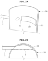
FIG. 2A is a partially cut-away view schematically illustrating a coupling portion between a hopper part and a second transfer line; -
FIG. 2B is a cross-sectional view schematically illustrating the coupling portion between the hopper part and the second transfer line; -
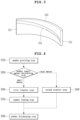
FIG. 3 is a view schematically illustrating another example of an anti-abrasion plate to be employed in the hopper part; and -
FIG. 4 is a flowchart illustrating a powder transfer method using the vacuum-type powder transfer system according to the present disclosure. - The objectives, specific advantages, and novel features of the present disclosure will be more clearly understood from the following detailed description and preferable embodiments when taken in conjunction with the accompanying drawings. As for reference numerals associated with parts in the drawings, the same reference numerals will refer to the same or like parts throughout the drawings. Further, in the following description of the present disclosure, a detailed description of related known configurations or functions may be omitted to avoid obscuring the subject matter of the present disclosure. It will be understood that, although the terms "first surface", "second surface", "first", "second", etc. may be used only to distinguish one element from another element, these elements should not be limited by these terms. In the drawings, some components are exaggerated, omitted, or schematically illustrated, and the size of each component does not exactly reflect its real size.
- Hereinbelow, an exemplary embodiment of the present disclosure will be described in detail with reference to the accompanying drawings.
- The present disclosure relates to a powder transfer system capable of sucking powder used for product production through a vacuum suction method and transferring it to downstream equipment, and includes a storage part, a chamber part, a hopper part, and a vacuum pressure forming part. Here, the powder may be an electrode active material processed into a granular or powdery form required for manufacturing a secondary battery, and the electrode active material includes a cathode active material or an anode active material.
- Referring to
FIG. 1 , a vacuum-type powder transfer system according to the present disclosure includes astorage part 100 for storing powder, one ormore chamber parts 200 for accommodating the powder supplied from thestorage part 100, and ahopper part 300 disposed under the one ormore chamber parts 200, and a vacuumpressure forming part 400 for providing vacuum pressure inside the one ormore chamber parts 200. - As described above, the
storage part 100 is configured to guide the powder downstream while storing the powder. - In particular, in the present disclosure, the powder may be selectively guided to the one or
more chamber parts 200 or thehopper part 300. In other words, in the present disclosure, the powder may be sucked and guided by means of a branch pipe Y along a powder transfer path from thestorage part 100 to the one ormore chamber parts 200 or thehopper part 300. The branch pipe Y may be any diverting means capable of branching from a common transfer line into two transfer lines. - Specifically, in the present disclosure, a common transfer line L connected to the
storage part 100, a first transfer line L1 connected to the at last onechamber part 200, and a second transfer line L2 connected to thehopper part 300 may be connected to each other by the Y-shaped branch pipe Y. Optionally, each of the common transfer line L, the first transfer line L1, and the second transfer line L2 may be a flexible tube made of a material having mechanical properties, abrasion resistance, and chemical resistance even in collision/contact with the powdery electrode active material, for example, a urethane material. - As illustrated, the Y-shaped branch pipe Y branches into two branches of the first transfer line L1 and the second transfer line L2 from the common transfer line L. As a result, the powder may be split and supplied to the one or
more chamber parts 200 or thehopper part 300. - In addition, the present disclosure may selectively divert the powder transfer path to the
chamber part 200 and thehopper part 300 and/or control a supply amount of the powder by means of a valve. To this end, the present disclosure may include a main valve V for opening and closing the common transfer line L to control the flow of the powder supplied downstream from thestorage part 100, and a first valve V1 for opening and closing the first transfer line L1 to control the flow of the powder supplied to the one ormore chamber parts 200. Correspondingly, the present disclosure may include a second valve V2 for opening and closing the second transfer line L2 to control the flow of the powder supplied to thehopper part 300. As illustrated, the main valve V couples an outlet end of the common transfer line L to an inlet end of the Y-shaped branch pipe Y, the first valve V1 couples an first side outlet end of the Y-shaped branch pipe Y to an inlet end of the first transfer line L1, and the second valve V2 couples a second side outlet end of the Y-shaped branch pipe Y to an inlet end of the second transfer line L2. With this structure, the present disclosure may guide the powder from thestorage part 100 to the one ormore chamber parts 200 or from thestorage part 100 to thehopper part 300 according to an operator's selection through opening and closing of the first and second valves V1 and V2. In the embodiment of the present disclosure, each of the main valve V, the first valve V1, and the second valve V2 may be configured as a solenoid valve that precisely controls the transfer path and supply amount of the powder. - In addition, a lining for abrasion protection, preferably a ceramic lining, may be additionally disposed in an inner flow path of the branch pipe Y. During transfer of the powder, the branch pipe Y may change the direction of the powder toward the first transfer line L1 or the second transfer line L inside the branch pipe Y through the lining described above to prevent abrasion of the inner flow path due to collision of the powder with the inner flow path of the branch pipe Y, thereby extending lifespan of the branch pipe Y.
- The one or
more chamber parts 200 receive the powder through the common transfer line L and the first transfer line L1 and temporarily store it therein. As illustrated, the one ormore chamber parts 200 may be positioned on top of the hopper part 30 in a parallel arrangement with respect to thestorage part 100. - In the present disclosure, air is sucked together with the powder from the
storage part 100 by vacuum pressure of the vacuumpressure forming part 400 into each of thechamber parts 200. While the powder is collected in a lower portion of thechamber part 200 under influence of gravity, the air is discharged into the atmosphere through a process of creating a vacuum inside thechamber part 200 by driving the vacuumpressure forming part 400. The powder accommodated in each of the small-capacity chamber parts 200 is discharged into the large-capacity hopper part 300 by opening an opening/closing valve V3. Of course, thechamber parts 200 may each sequentially and quantitatively supply a constant amount of the powder to thehopper part 300, which is downstream equipment, by sequentially opening the opening/closing valve V3. - As is well known to those skilled in the art, the vacuum
pressure forming part 400 may be, for example, a vacuum conveyor, and creates a vacuum inside each of thechamber parts 200 while discharging air to the outside through a vacuum hose (not illustrated) connected to each of thechamber parts 200 by driving a vacuum pump. In this case, due to a difference in pressure between thestorage part 100 and thechamber parts 200, the powder is sucked into each of thechamber parts 200 and flows. The vacuumpressure forming part 400 may include a filter for blocking movement of the powder toward the vacuum pump. - Each of the one or
more chamber parts 200 may include the opening/closing valve V3 for controlling the transfer of the powder from the inside of thechamber part 300 to thehopper part 300, and a weight sensor (not illustrated) for measuring the weight of the powder supplied to thechamber part 200. The powder transfer system according to the present disclosure may block or restart suction of the powder into the one ormore chamber parts 200 by comparing a powder supply amount detected by the weight sensor disposed under each of thechamber parts 200 with a powder storage capacity preset for each of thechamber parts 200. - In the present disclosure, the
hopper part 300 is provided under the one ormore chamber parts 200 to be in fluid communication therewith. More specifically, thehopper part 300 is disposed such that the fluid communication thereof with the one ormore chamber parts 200 is controlled. That is, thehopper part 300 may open the opening/closing valve V3 of each of thechamber parts 200 to receive the powder accommodated in each of thechamber parts 200, and receive a large amount of the powder through the common transfer line L and the second transfer line L2. - In addition, the
hopper part 300 may include a weight sensor (not illustrated) for measuring the weight of the powder supplied to thehopper part 300. The suction of the powder into thehopper part 300 may be blocked or restarted by comparing a powder supply amount detected by the weight sensor disposed under thehopper part 300 and a power storage capacity preset for thehopper part 300. - As described above, the
hopper part 300 is configured to receive the powder directly from thestorage part 100 without passing through thechamber parts 200. That is, the powder may be sucked into thehopper part 300 through the common transfer line L, the Y-shaped branch pipe Y, and the second transfer line L2 from thestorage part 100. To this end, the present disclosure creates a vacuum inside thehopper part 300 by driving the vacuumpressure forming part 400 to allow inflow of the powder from thestorage part 100 into thehopper part 300, and implements suction of a large amount of the powder under opening of the opening/closing valve V3 for controlling fluid communication between each of thechamber parts 200 and thehopper part 300. - Preferably, in the present disclosure, as illustrated in
FIGS. 2A and 2B , an outlet end of the second transfer line L2 is insertedly installed in communication with an inner wall of thehopper part 300 in a tangential direction in order to rotate the powder to be introduced through the second transfer line L2 along the inner wall of thehopper part 300. Therefore, the powder is introduced into an inner space of thehopper part 300, that is, a rotating space, in the tangential direction, and rotates and flows along the inner wall of thehopper part 300 in a circumferential direction. This induces a uniform flow rate distribution of the powder in the inner space of thehopper part 300 to prevent the accumulation of the powder in a region where the flow rate is low and to prevent adhesion/aggregation of the powder on the inner wall of thehopper part 300. Furthermore, the rotation of the powder in thehopper part 300 helps to easily collect the powder to a tapered lower portion of thehopper part 300 in a gravity sedimentation method. - The powder introduced tangentially to the inner wall of the
hopper part 300 through the second transfer line L2 as described above collides with the inner wall of thehopper part 300 and causes abrasion of the inner wall. For this reason, ananti-abrasion plate 310 is disposed in front of the outlet end of the second transfer line L2. Theanti-abrasion plate 310 may be made of a ceramic material having a smooth surface, but is not limited thereto, and may also be made of a metal material having a smooth surface. - As illustrated, the
anti-abrasion plate 310 may extend in a curved shape along the inner wall of thehopper part 300 so as to be in close contact with the inner wall of thehopper part 300. Theanti-abrasion plate 310 has aproximal end 311 adjacent to the outlet end of the second transfer line L2 and adistal end 312 opposite to the proximal end in a longitudinal direction (or circumferential direction). Theanti-abrasion plate 310 may extend such that a virtual axis D (indicated by a dashed-dotted line inFIG. 2B ) extending from an inner side of an outer peripheral surface of the outlet end of the second transfer line L2 toward the inner wall of thehopper part 300 is positioned in an inner region of theanti-abrasion plate 310. In other words, the virtual axis D is disposed between theproximal end 311 and thedistal end 312. - Optionally, the powder falls to the lower portion of the
hopper part 300 while it rotates along the inner wall of thehopper part 300. In this case, the present disclosure may be designed to forcibly guide a rotating flow of the powder to be inclined downward along the circumferential direction of the inner wall of thehopper part 300. To this end, theanti-abrasion plate 310 disposed in front of the outlet end of the second transfer line L2 includes a thin andelongated guide protrusion 313 inclined downward in a longitudinal direction of the anti-abrasion plate 310 (seeFIG. 3 ). Theguide protrusion 313 extends at a downwardly inclined slope from theproximal end 311 to thedistal end 312 of theanti-abrasion plate 310 so as to guide the powder to fall in a vortex shape, thereby preventing a turbulent flow from occurring in thehopper part 300 due to scattering of the powder. - As illustrated, the
hopper part 300 has a conical structure at the lower portion thereof to help efficient downward movement of the powder. Therefore, thehopper part 300 of the present disclosure is in communication with unillustrated downstream equipment, for example, a mixing part, to discharge the powder. -
FIG. 4 is a flowchart illustrating a powder transfer method using the vacuum-type powder transfer system according to the present disclosure. - As described above, since the vacuum-type powder transfer system according to the present disclosure is designed to quantitatively supply a constant amount of the powder in a wide range from a small amount to a large amount by a vacuum suction method, the powder transfer method will be described in more detail with reference to the flowchart of
FIG. 4 . - The present disclosure is configured to control the amount of powder supplied from a
storage part 100 to downstream equipment, and includes astep S 100 of providing the powder to thestorage part 100. - Here, the powder may be a powdery electrode active material required for manufacturing a secondary battery. The powder may be transferred to a mixing part, which is downstream equipment, through the vacuum-type powder transfer system of the present disclosure to be processed into a mixed material having specific properties.
- In order to prevent a problem due to insufficient or excessive input of the powder to the mixing part, the present disclosure is configured to quantitatively supply a constant amount of the powder according to a preset amount. After the powder is prepared, the present disclosure includes a step S200 of determining a powder supply amount to transfer the powder in a preset amount using the vacuum transfer system (see
FIG. 1 ). - Through the step S200 of determining the powder supply amount, the present disclosure may selectively quantitatively supply a constant amount of the powder in a wide range from a small amount to a large amount.
- In the present disclosure, one or
more chamber parts 200 are provided on the top of ahopper part 300, and each of thechamber parts 200 is connected to a vacuumpressure forming part 400. As illustrated, each of thechamber parts 200 may be, for example, a relatively small-capacity chamber having a storage capacity of 50 kg, and thehopper part 300 may be, for example, a relatively large-capacity hopper having a storage capacity of equal to or greater than 50 kg. - When the powder supply amount is set to be less than the storage capacity of the chamber part 200 (that is, when the powder supply amount is small), the present disclosure includes a first transfer step S300 of sucking the powder from the
storage part 100 to the one ormore chamber parts 200. In the first transfer step S300, a main valve V and a first valve V1 are opened through the operation of a controller (not illustrated) and the vacuumpressure forming part 400 is driven to create a vacuum inside each of thechamber parts 200, so that the powder stored in thestorage part 100 is guided into the one ormore chamber parts 200 along a first powder transfer path composed of a common transfer line L, a branch pipe Y, and a first transfer line L1. At this time, a second valve V2 is maintained in a closed state to control transfer of the powder to thehopper part 300. An opening/closing valve V3 is provided between each of thechamber parts 200 and thehopper part 300, so that a constant amount of the powder is stored in each of thechamber parts 200. - After the constant amount of the powder corresponding to a preset amount is supplied to each of the
chamber parts 200 through the first transfer step S300, the present disclosure includes a step S310 of feeding the powder from each of thechamber parts 200 into thehopper part 300. In the step S310 of feeding the powder, the operation of the vacuumpressure forming part 400 is stopped and the opening/closing valve V3 is opened to guide the powder accommodated in each of the small-capacity chamber parts 200 into the large-capacity hopper part 300. - On the other hand, when the powder supply amount is set to be greater than the storage capacity of the chamber part 200 (that is, when the powder supply amount is large), the present disclosure includes a second transfer step S400 of sucking the powder from the
storage part 100 to thehopper part 300. - In the second transfer step S400, the main valve V, the second valve V2, and the opening/closing valve V3 are opened through the operation of the controller and the vacuum
pressure forming part 400 is driven to create a vacuum created inside each of thechamber parts 200 and thehopper part 300, so that the powder stored in thestorage part 100 is guided into thehopper part 300 along a second powder transfer path composed of the common transfer line L, the branch pipe Y, and a second transfer line L2. At this time, the first valve V1 is maintained in a closed state to control transfer of the powder to each of thechamber parts 200. - Optionally, in the present disclosure, in order to supply a large amount of the powder to the mixing part more quickly and more precisely, the powder may be transferred first to the
hopper part 300 through the second transfer step S400 until a weight sensor senses that about 95% of a set supply amount of the powder is reached, and then the second transfer step S400 may be stopped and the first transfer step S300 may be operated to supply about 5% of the set supply amount of the powder (here, 5% is less than or equal to the storage capacity of the chamber part 200) to the one ormore chamber parts 200 to supply a preset amount of the powder to the mixing part. This makes it possible to accurately control the powder supply amount according to the set supply amount and to significantly reduce transfer speed of the powder compared to when only the small-capacity chamber parts 200 are operated. The description above is merely an example for supplying the powder at the set supply amount through the first transfer step S300 after the second transfer step S400, and the present disclosure is not limited thereto. The present disclosure may be selected from the group consisting of the first transfer step S300, the second transfer step S400, or a combination thereof in order to quantitatively supply a constant amount of the powder in a range from a small amount to a large amount. - After the step S310 of feeding the powder and/or the second transfer step S400, the transfer of the powder is finished through a step S500 of discharging the powder to downstream equipment by opening an opening/closing means (not illustrated) provided under the
hopper part 300. - While exemplary embodiments of the present disclosure have been described above for the illustrative purposes, the vacuum-type powder transfer system and method according to the present disclosure are not limited to the embodiments described above, and it will be understood by those skilled in the art that the present disclosure can be modified or changed in various forms without departing from the technical spirit of the present disclosure.
- Simple modifications or changes of the present disclosure belong to the scope of the present disclosure, and the detailed scope of the present disclosure will be more clearly understood by the accompanying claims.
Claims (11)
- A vacuum-type powder transfer system comprising:a storage part configured to store powder;one or more chamber parts configured to accommodate the powder transferred from the storage part;a hopper part disposed to control fluid communication with the one or more chamber parts, and configured to accommodate the powder transferred from the storage part; anda vacuum pressure forming part configured to provide vacuum pressure to the one or more chamber parts,wherein the powder is split and supplied to the one or more chamber parts or the hopper part.
- The vacuum-type powder transfer system of claim 1, further comprising:a common transfer line connected to the storage part;a first transfer line connected to the one or more chamber parts;a second transfer line connected to the hopper part; anda branch pipe connected to the common transfer line and configured to supply the powder by diverting the powder to the first transfer line or the second transfer line.
- The vacuum-type powder transfer system of claim 1 or 2, wherein the hopper part further comprises an anti-abrasion plate in front of an outlet end of the second transfer line, the outlet end being inserted in a tangential direction into an inner wall of the hopper part.
- The vacuum-type powder transfer system of claim 3, wherein the anti-abrasion plate is configured such that a virtual axis extending from an inner side of an outer peripheral surface of the outlet end of the second transfer line toward the inner wall of the hopper part is disposed between a proximal end and a distal end of the anti-abrasion plate.
- The vacuum-type powder transfer system of anyone of claims 1 to 4, wherein the hopper part is disposed under the one or more chamber parts.
- The vacuum-type powder transfer system of anyone of claims 1 to 5, wherein the hopper part has a storage capacity larger than a storage capacity of each of the chamber parts.
- A vacuum-type powder transfer method using the vacuum-type powder transfer system of any one of claims 1 to 6, the vacuum-type powder transfer method comprising:a step of providing the powder to the storage part;a step of determining a powder supply amount;a first transfer step of sucking the powder from the storage part to the one or more chamber parts when the powder supply amount is equal to or less than the storage capacity of each of the chamber parts;a second transfer step of sucking the powder from the storage part to the hopper part when the powder supply amount is greater than the storage capacity of each of the chamber parts; anda step of discharging the powder accommodated in the hopper part to downstream equipment.
- The vacuum-type powder transfer method of claim 7, further comprising a step of feeding the powder from the one or more chamber parts to the hopper part after the first transfer step.
- The vacuum-type powder transfer method of claim 7 or 8, wherein the second transfer step further comprises a step of allowing the chamber parts and the hopper part to be in fluid communication with each other and providing the vacuum pressure to each of the chamber parts and the hopper part by the vacuum pressure forming part.
- The vacuum-type powder transfer method of anyone of claims 7 to 9, wherein in the second transfer step, the powder rotates and flows along the inner wall of the hopper part.
- The vacuum-type powder transfer method of anyone of claims 7 to 10, wherein the powder is guided to a powder transfer path selected from the group consisting of the first transfer step, the second transfer step, or a combination thereof.
Priority Applications (1)
| Application Number | Priority Date | Filing Date | Title |
|---|---|---|---|
| EP25193086.3A EP4620875A3 (en) | 2022-02-18 | 2022-10-21 | Vacuum-type powder transfer system and method |
Applications Claiming Priority (1)
| Application Number | Priority Date | Filing Date | Title |
|---|---|---|---|
| KR1020220021502A KR102610699B1 (en) | 2022-02-18 | 2022-02-18 | Vacuum type powder transfer system and method thereof |
Related Child Applications (2)
| Application Number | Title | Priority Date | Filing Date |
|---|---|---|---|
| EP25193086.3A Division EP4620875A3 (en) | 2022-02-18 | 2022-10-21 | Vacuum-type powder transfer system and method |
| EP25193086.3A Division-Into EP4620875A3 (en) | 2022-02-18 | 2022-10-21 | Vacuum-type powder transfer system and method |
Publications (2)
| Publication Number | Publication Date |
|---|---|
| EP4303159A1 true EP4303159A1 (en) | 2024-01-10 |
| EP4303159B1 EP4303159B1 (en) | 2025-09-17 |
Family
ID=83994953
Family Applications (2)
| Application Number | Title | Priority Date | Filing Date |
|---|---|---|---|
| EP22203151.0A Active EP4303159B1 (en) | 2022-02-18 | 2022-10-21 | Vacuum-type powder transfer system and method |
| EP25193086.3A Pending EP4620875A3 (en) | 2022-02-18 | 2022-10-21 | Vacuum-type powder transfer system and method |
Family Applications After (1)
| Application Number | Title | Priority Date | Filing Date |
|---|---|---|---|
| EP25193086.3A Pending EP4620875A3 (en) | 2022-02-18 | 2022-10-21 | Vacuum-type powder transfer system and method |
Country Status (5)
| Country | Link |
|---|---|
| US (2) | US11713201B1 (en) |
| EP (2) | EP4303159B1 (en) |
| KR (2) | KR102610699B1 (en) |
| CN (2) | CN116409633B (en) |
| PL (1) | PL4303159T3 (en) |
Families Citing this family (1)
| Publication number | Priority date | Publication date | Assignee | Title |
|---|---|---|---|---|
| TR202108697A2 (en) * | 2021-05-26 | 2021-06-21 | Balsu Gida Sanayi Ve Ticaret Anonim Sirketi | A HANDLING SYSTEM TO BE USED TO REPLACE HAZELNUT |
Citations (5)
| Publication number | Priority date | Publication date | Assignee | Title |
|---|---|---|---|---|
| US4266673A (en) * | 1978-10-26 | 1981-05-12 | Wibau Maschinenfabrik Hartmann Ag | Apparatus for classifying dust materials |
| JP2506441Y2 (en) * | 1989-06-16 | 1996-08-07 | 株式会社松井製作所 | Suction transport device for powder and granular material |
| CN110203703A (en) * | 2019-06-17 | 2019-09-06 | 广东海洋大学 | A kind of continuous suction system of vacuum and feeding method |
| KR20200107146A (en) | 2019-03-06 | 2020-09-16 | 에스케이이노베이션 주식회사 | Automatic Powder Transfer System Using Vacuum Conveyor |
| US20210387802A1 (en) * | 2018-10-22 | 2021-12-16 | Maricap Oy | Method for handling material in a material conveying system, a separating device arrangement and a material conveying system |
Family Cites Families (46)
| Publication number | Priority date | Publication date | Assignee | Title |
|---|---|---|---|---|
| US3306671A (en) * | 1965-04-19 | 1967-02-28 | Stamicarbon | Method and apparatus for feeding material handling devices |
| DE2544716A1 (en) * | 1975-10-07 | 1977-04-21 | Zimmermann Azo Maschf | SUCTION CONVEYOR SYSTEM |
| US4197037A (en) * | 1978-01-23 | 1980-04-08 | Dede Edmund J | Tank distribution take-away system |
| US4341492A (en) * | 1980-02-19 | 1982-07-27 | R & M Associates, Inc. | Method for pneumatically handling agglomerative materials |
| DE3323162A1 (en) * | 1983-06-28 | 1985-01-03 | Motan Gmbh, 7972 Isny | Conveying device |
| US4900200A (en) * | 1988-06-22 | 1990-02-13 | Matsui Manufacturing Co., Ltd. | Method for transporting powdered or granular materials by pneumatic force with a transport pipe of smaller diameter relative to particale size |
| DE3934910A1 (en) * | 1989-10-20 | 1991-04-25 | Azo Gmbh & Co | PNEUMATIC SUCTION CONVEYOR FOR GRAVIMETRICALLY ALLOCATING SCHUETTGUT COMPONENTS |
| JP2847580B2 (en) * | 1990-12-14 | 1999-01-20 | コニカ株式会社 | Pipeline transport system of cylindrical container by air |
| US5322074A (en) * | 1992-07-01 | 1994-06-21 | The Cardwell Machine Company | Tobacco delivery system |
| JPH0612479U (en) | 1992-07-21 | 1994-02-18 | 帝人株式会社 | Mixing device for powder and granules |
| GB9307780D0 (en) * | 1993-04-15 | 1993-06-02 | Technivac Ltd | Method of charging a vessel with particulate material |
| US5645381A (en) * | 1994-09-13 | 1997-07-08 | Trw Inc. | Variable-split blowdown coal feed system |
| AT402816B (en) * | 1995-10-19 | 1997-09-25 | Voest Alpine Ind Anlagen | METHOD FOR CONVEYING A FINE-PARTICLE SOLID |
| US6068429A (en) * | 1998-02-19 | 2000-05-30 | Transfer Industrial Leasing, Inc. | Air conveying apparatus |
| JP2000128543A (en) | 1998-10-30 | 2000-05-09 | Kawasaki Steel Corp | Roasting furnace for iron oxide production |
| KR20000012498U (en) * | 1998-12-18 | 2000-07-05 | 이구택 | Solid Material Transfer Device |
| GB0121353D0 (en) * | 2001-09-04 | 2001-10-24 | Rig Technology Ltd | Improvements in or relating to transport of waste materials |
| US6776561B1 (en) * | 2003-11-28 | 2004-08-17 | Neng-Kuei Yeh | Materials collecting apparatus with weighing and vacuum sucking functions |
| US7228990B2 (en) * | 2003-12-15 | 2007-06-12 | Polymer Group, Inc. | Unitized fibrous construct dispensing system |
| FI118528B (en) * | 2004-03-03 | 2007-12-14 | Maricap Oy | Method and apparatus for moving material |
| DE102004019703A1 (en) * | 2004-04-20 | 2006-01-12 | Volkmann Gesellschaft mit beschränkter Haftung | Method and device for inerting vacuum conveyors |
| RU2395442C2 (en) * | 2005-12-07 | 2010-07-27 | Марикап Ой | Method and device for material transportation and ejector device |
| GB2438929B (en) * | 2006-06-07 | 2011-10-26 | Catalyst Handling Res & Engineering Ltd | Improved particulate handling apparatus and method |
| US7972087B2 (en) * | 2007-09-07 | 2011-07-05 | Food Processing Equipment Company | Vacuum transfer apparatus and process with improved product weighing controls |
| US7854205B2 (en) * | 2008-10-30 | 2010-12-21 | Straw Track Manufacturing Inc. | Chamber for slowing particles flowing in a pneumatic conveyor conduit |
| US8430605B2 (en) * | 2009-01-21 | 2013-04-30 | Jeffrey Dietterich | Pneumatic conveyance system including waste airflow electrical power generation |
| EP2403037B1 (en) | 2009-02-24 | 2016-05-04 | Panasonic Intellectual Property Management Co., Ltd. | Electrode plate for nonaqueous secondary battery, manufacturing method therefor, and nonaqueous secondary battery using same |
| US8147169B1 (en) * | 2009-05-20 | 2012-04-03 | Kvalheim Andrew M | Apparatus for extracting and delivering articles in amounts of uniform size |
| US8747029B2 (en) * | 2010-05-03 | 2014-06-10 | Mac Equipment, Inc. | Low pressure continuous dense phase convey system using a non-critical air control system |
| EP2694199B1 (en) * | 2011-04-04 | 2016-07-06 | Proven Technologies, LLC | Accurate dry bulk handling system and method of use |
| US8770120B2 (en) * | 2011-05-24 | 2014-07-08 | Cnh Industrial Canada, Ltd. | Method and apparatus for distributing seed from a central source to a plurality of seed metering units of an agricultural seeding machine |
| RU2535821C1 (en) * | 2013-10-31 | 2014-12-20 | Закрытое Акционерное Общество "Твин Трейдинг Компани" | Air vacuum device for transfer of loose materials with high weight concentration |
| KR101678813B1 (en) | 2014-01-28 | 2016-11-23 | 주식회사 엘지화학 | Electrode Comprising Active-Material-Non-Coated Portion with thick thickness |
| US10138076B2 (en) * | 2015-02-25 | 2018-11-27 | Stephen B. Maguire | Method for resin delivery including metering introduction of external air to maintain desired vacuum level |
| CA2979987A1 (en) * | 2015-03-19 | 2016-09-22 | Ipeg, Inc. | Pressure differential proofing method for pneumatic conveying |
| KR101830287B1 (en) | 2015-06-01 | 2018-02-20 | 주식회사 엘지화학 | Electrode Rolling Device Capable of Preventing Swell or Wrinkle of Electrode Sheet by Rolling Work |
| US10703590B1 (en) | 2016-04-29 | 2020-07-07 | Roy Howard Struble, Jr. | Dry material delivery system for dry bulk containers |
| CN205932468U (en) * | 2016-08-17 | 2017-02-08 | 柳州市豪杰特化工机械有限责任公司 | Powder is thrown and is foreseen negative pressure multiple spot air conveying system |
| LU93234B1 (en) * | 2016-09-23 | 2018-04-05 | Wurth Paul Sa | Material hopper, in particular for a blast furnace |
| KR101865808B1 (en) | 2016-09-29 | 2018-06-11 | 조명률 | Power Transfer Apparatus |
| US10259184B2 (en) | 2017-04-03 | 2019-04-16 | Ford Motor Company | Aluminum dust collection and compacting apparatus |
| CN107826769A (en) * | 2017-11-29 | 2018-03-23 | 青岛科技大学 | A kind of novel material storage and induction system |
| CN208427037U (en) * | 2018-05-24 | 2019-01-25 | 江苏安迪化学药业有限公司 | Synthesizing hydrophobic monomer N- alkyl acrylamide reaction kettle |
| FI129115B (en) | 2020-01-14 | 2021-07-15 | Maricap Oy | Method for conveying material in a pneumatic material conveying system, and pneumatic material conveying system |
| KR102611670B1 (en) | 2020-04-29 | 2023-12-14 | 에스케이온 주식회사 | Ultra Dispersion Mixer |
| KR102453390B1 (en) * | 2022-03-25 | 2022-10-11 | 정종호 | Apparatus for transporting powdery active material of secondary battery |
-
2022
- 2022-02-18 KR KR1020220021502A patent/KR102610699B1/en active Active
- 2022-10-21 PL PL22203151.0T patent/PL4303159T3/en unknown
- 2022-10-21 EP EP22203151.0A patent/EP4303159B1/en active Active
- 2022-10-21 EP EP25193086.3A patent/EP4620875A3/en active Pending
- 2022-10-24 CN CN202211307862.XA patent/CN116409633B/en active Active
- 2022-10-24 CN CN202411111733.2A patent/CN118723575A/en active Pending
- 2022-12-29 US US18/148,250 patent/US11713201B1/en active Active
-
2023
- 2023-07-27 US US18/360,658 patent/US11897709B2/en active Active
- 2023-11-30 KR KR1020230170967A patent/KR102789276B1/en active Active
Patent Citations (5)
| Publication number | Priority date | Publication date | Assignee | Title |
|---|---|---|---|---|
| US4266673A (en) * | 1978-10-26 | 1981-05-12 | Wibau Maschinenfabrik Hartmann Ag | Apparatus for classifying dust materials |
| JP2506441Y2 (en) * | 1989-06-16 | 1996-08-07 | 株式会社松井製作所 | Suction transport device for powder and granular material |
| US20210387802A1 (en) * | 2018-10-22 | 2021-12-16 | Maricap Oy | Method for handling material in a material conveying system, a separating device arrangement and a material conveying system |
| KR20200107146A (en) | 2019-03-06 | 2020-09-16 | 에스케이이노베이션 주식회사 | Automatic Powder Transfer System Using Vacuum Conveyor |
| CN110203703A (en) * | 2019-06-17 | 2019-09-06 | 广东海洋大学 | A kind of continuous suction system of vacuum and feeding method |
Also Published As
| Publication number | Publication date |
|---|---|
| EP4620875A3 (en) | 2025-12-17 |
| CN116409633B (en) | 2024-08-30 |
| KR102789276B1 (en) | 2025-04-01 |
| CN116409633A (en) | 2023-07-11 |
| US20230264903A1 (en) | 2023-08-24 |
| PL4303159T3 (en) | 2026-01-19 |
| EP4303159B1 (en) | 2025-09-17 |
| KR20230124331A (en) | 2023-08-25 |
| US11897709B2 (en) | 2024-02-13 |
| CN118723575A (en) | 2024-10-01 |
| KR102610699B1 (en) | 2023-12-06 |
| KR20230169026A (en) | 2023-12-15 |
| EP4620875A2 (en) | 2025-09-24 |
| US11713201B1 (en) | 2023-08-01 |
| US20230365353A1 (en) | 2023-11-16 |
Similar Documents
| Publication | Publication Date | Title |
|---|---|---|
| US5746258A (en) | Apparatus for filling a container with free-flowing bulk material | |
| US4846608A (en) | Pneumatic grain conveyor and related method | |
| EP4620875A2 (en) | Vacuum-type powder transfer system and method | |
| CN102015497A (en) | Method and apparatus for transporting a particulate material | |
| KR102736658B1 (en) | Automatic Powder Transfer System Using Vacuum Conveyor | |
| RU2005106239A (en) | METHOD AND DEVICE FOR SUBMITTING DUSTY MATERIAL | |
| CA2560109A1 (en) | Portable storage apparatus for granular material | |
| CN115108328A (en) | Pneumatic conveying pump capable of conveying quantitatively and facilitating internal cleaning | |
| CN103407788B (en) | Constant volume type accurate metering feeder and pneumatic blowing equipment | |
| FI130019B (en) | Method for handling material in a material transport system, separator arrangement and material transport system | |
| KR102529972B1 (en) | Device for continuous weighing of pourable materials | |
| JP7286163B2 (en) | Feeder and plug feeder | |
| CN217807446U (en) | Double Bucket Continuous Vacuum Feeder | |
| CN212355782U (en) | Pulping system based on bin pump | |
| CN217050668U (en) | Negative pressure conveying system | |
| CN221116024U (en) | Material mixing and distributing device for powder | |
| CA1286538C (en) | Vertical hydro-hoist and method of operating the same | |
| CN114803519A (en) | Double-bucket continuous vacuum charging machine | |
| CN112337381A (en) | Intelligent automatic blending machine equipment | |
| CN222930764U (en) | Servo discharge mechanism | |
| US20250206546A1 (en) | Device and Method for Recovering and Re-Injecting Excess Powder | |
| CN215842424U (en) | Material injection device for desulfurization | |
| CN219906096U (en) | Pneumatic conveying system for unloading steel plate bin | |
| CN115466634B (en) | Pulverized coal lock bucket | |
| CN218893649U (en) | Cell separation apparatus |
Legal Events
| Date | Code | Title | Description |
|---|---|---|---|
| PUAI | Public reference made under article 153(3) epc to a published international application that has entered the european phase |
Free format text: ORIGINAL CODE: 0009012 |
|
| STAA | Information on the status of an ep patent application or granted ep patent |
Free format text: STATUS: REQUEST FOR EXAMINATION WAS MADE |
|
| 17P | Request for examination filed |
Effective date: 20221021 |
|
| AK | Designated contracting states |
Kind code of ref document: A1 Designated state(s): AL AT BE BG CH CY CZ DE DK EE ES FI FR GB GR HR HU IE IS IT LI LT LU LV MC ME MK MT NL NO PL PT RO RS SE SI SK SM TR |
|
| RBV | Designated contracting states (corrected) |
Designated state(s): AL AT BE BG CH CY CZ DE DK EE ES FI FR GB GR HR HU IE IS IT LI LT LU LV MC ME MK MT NL NO PL PT RO RS SE SI SK SM TR |
|
| STAA | Information on the status of an ep patent application or granted ep patent |
Free format text: STATUS: EXAMINATION IS IN PROGRESS |
|
| 17Q | First examination report despatched |
Effective date: 20241121 |
|
| GRAP | Despatch of communication of intention to grant a patent |
Free format text: ORIGINAL CODE: EPIDOSNIGR1 |
|
| STAA | Information on the status of an ep patent application or granted ep patent |
Free format text: STATUS: GRANT OF PATENT IS INTENDED |
|
| INTG | Intention to grant announced |
Effective date: 20250422 |
|
| GRAS | Grant fee paid |
Free format text: ORIGINAL CODE: EPIDOSNIGR3 |
|
| GRAA | (expected) grant |
Free format text: ORIGINAL CODE: 0009210 |
|
| STAA | Information on the status of an ep patent application or granted ep patent |
Free format text: STATUS: THE PATENT HAS BEEN GRANTED |
|
| P01 | Opt-out of the competence of the unified patent court (upc) registered |
Free format text: CASE NUMBER: UPC_APP_1597_4303159/2025 Effective date: 20250731 |
|
| AK | Designated contracting states |
Kind code of ref document: B1 Designated state(s): AL AT BE BG CH CY CZ DE DK EE ES FI FR GB GR HR HU IE IS IT LI LT LU LV MC ME MK MT NL NO PL PT RO RS SE SI SK SM TR |
|
| REG | Reference to a national code |
Ref country code: GB Ref legal event code: FG4D |
|
| REG | Reference to a national code |
Ref country code: CH Ref legal event code: EP |
|
| REG | Reference to a national code |
Ref country code: DE Ref legal event code: R096 Ref document number: 602022021514 Country of ref document: DE |
|
| REG | Reference to a national code |
Ref country code: IE Ref legal event code: FG4D |
|
| PGFP | Annual fee paid to national office [announced via postgrant information from national office to epo] |
Ref country code: DE Payment date: 20251028 Year of fee payment: 4 |
|
| PG25 | Lapsed in a contracting state [announced via postgrant information from national office to epo] |
Ref country code: NO Free format text: LAPSE BECAUSE OF FAILURE TO SUBMIT A TRANSLATION OF THE DESCRIPTION OR TO PAY THE FEE WITHIN THE PRESCRIBED TIME-LIMIT Effective date: 20251217 |
|
| REG | Reference to a national code |
Ref country code: LT Ref legal event code: MG9D |
|
| PGFP | Annual fee paid to national office [announced via postgrant information from national office to epo] |
Ref country code: AT Payment date: 20260113 Year of fee payment: 4 |
|
| PG25 | Lapsed in a contracting state [announced via postgrant information from national office to epo] |
Ref country code: FI Free format text: LAPSE BECAUSE OF FAILURE TO SUBMIT A TRANSLATION OF THE DESCRIPTION OR TO PAY THE FEE WITHIN THE PRESCRIBED TIME-LIMIT Effective date: 20250917 |
|
| PG25 | Lapsed in a contracting state [announced via postgrant information from national office to epo] |
Ref country code: HR Free format text: LAPSE BECAUSE OF FAILURE TO SUBMIT A TRANSLATION OF THE DESCRIPTION OR TO PAY THE FEE WITHIN THE PRESCRIBED TIME-LIMIT Effective date: 20250917 |
|
| PG25 | Lapsed in a contracting state [announced via postgrant information from national office to epo] |
Ref country code: GR Free format text: LAPSE BECAUSE OF FAILURE TO SUBMIT A TRANSLATION OF THE DESCRIPTION OR TO PAY THE FEE WITHIN THE PRESCRIBED TIME-LIMIT Effective date: 20251218 |
|
| PG25 | Lapsed in a contracting state [announced via postgrant information from national office to epo] |
Ref country code: SE Free format text: LAPSE BECAUSE OF FAILURE TO SUBMIT A TRANSLATION OF THE DESCRIPTION OR TO PAY THE FEE WITHIN THE PRESCRIBED TIME-LIMIT Effective date: 20250917 |
|
| REG | Reference to a national code |
Ref country code: NL Ref legal event code: MP Effective date: 20250917 |
|
| PG25 | Lapsed in a contracting state [announced via postgrant information from national office to epo] |
Ref country code: LV Free format text: LAPSE BECAUSE OF FAILURE TO SUBMIT A TRANSLATION OF THE DESCRIPTION OR TO PAY THE FEE WITHIN THE PRESCRIBED TIME-LIMIT Effective date: 20250917 |
|
| PG25 | Lapsed in a contracting state [announced via postgrant information from national office to epo] |
Ref country code: BG Free format text: LAPSE BECAUSE OF FAILURE TO SUBMIT A TRANSLATION OF THE DESCRIPTION OR TO PAY THE FEE WITHIN THE PRESCRIBED TIME-LIMIT Effective date: 20250917 |
|
| PGFP | Annual fee paid to national office [announced via postgrant information from national office to epo] |
Ref country code: PL Payment date: 20251007 Year of fee payment: 4 |
|
| PG25 | Lapsed in a contracting state [announced via postgrant information from national office to epo] |
Ref country code: RS Free format text: LAPSE BECAUSE OF FAILURE TO SUBMIT A TRANSLATION OF THE DESCRIPTION OR TO PAY THE FEE WITHIN THE PRESCRIBED TIME-LIMIT Effective date: 20251217 |
|
| PG25 | Lapsed in a contracting state [announced via postgrant information from national office to epo] |
Ref country code: NL Free format text: LAPSE BECAUSE OF FAILURE TO SUBMIT A TRANSLATION OF THE DESCRIPTION OR TO PAY THE FEE WITHIN THE PRESCRIBED TIME-LIMIT Effective date: 20250917 |
|
| PGFP | Annual fee paid to national office [announced via postgrant information from national office to epo] |
Ref country code: HU Payment date: 20251020 Year of fee payment: 4 |
|
| REG | Reference to a national code |
Ref country code: AT Ref legal event code: MK05 Ref document number: 1838170 Country of ref document: AT Kind code of ref document: T Effective date: 20250917 |
|
| PG25 | Lapsed in a contracting state [announced via postgrant information from national office to epo] |
Ref country code: SM Free format text: LAPSE BECAUSE OF FAILURE TO SUBMIT A TRANSLATION OF THE DESCRIPTION OR TO PAY THE FEE WITHIN THE PRESCRIBED TIME-LIMIT Effective date: 20250917 |
|
| PG25 | Lapsed in a contracting state [announced via postgrant information from national office to epo] |
Ref country code: ES Free format text: LAPSE BECAUSE OF FAILURE TO SUBMIT A TRANSLATION OF THE DESCRIPTION OR TO PAY THE FEE WITHIN THE PRESCRIBED TIME-LIMIT Effective date: 20250917 |
|
| PG25 | Lapsed in a contracting state [announced via postgrant information from national office to epo] |
Ref country code: AT Free format text: LAPSE BECAUSE OF FAILURE TO SUBMIT A TRANSLATION OF THE DESCRIPTION OR TO PAY THE FEE WITHIN THE PRESCRIBED TIME-LIMIT Effective date: 20250917 |
|
| PG25 | Lapsed in a contracting state [announced via postgrant information from national office to epo] |
Ref country code: RO Free format text: LAPSE BECAUSE OF FAILURE TO SUBMIT A TRANSLATION OF THE DESCRIPTION OR TO PAY THE FEE WITHIN THE PRESCRIBED TIME-LIMIT Effective date: 20250917 Ref country code: IT Free format text: LAPSE BECAUSE OF FAILURE TO SUBMIT A TRANSLATION OF THE DESCRIPTION OR TO PAY THE FEE WITHIN THE PRESCRIBED TIME-LIMIT Effective date: 20250917 |
|
| PG25 | Lapsed in a contracting state [announced via postgrant information from national office to epo] |
Ref country code: IS Free format text: LAPSE BECAUSE OF FAILURE TO SUBMIT A TRANSLATION OF THE DESCRIPTION OR TO PAY THE FEE WITHIN THE PRESCRIBED TIME-LIMIT Effective date: 20260117 |
|
| PG25 | Lapsed in a contracting state [announced via postgrant information from national office to epo] |
Ref country code: PT Free format text: LAPSE BECAUSE OF FAILURE TO SUBMIT A TRANSLATION OF THE DESCRIPTION OR TO PAY THE FEE WITHIN THE PRESCRIBED TIME-LIMIT Effective date: 20260119 Ref country code: CZ Free format text: LAPSE BECAUSE OF FAILURE TO SUBMIT A TRANSLATION OF THE DESCRIPTION OR TO PAY THE FEE WITHIN THE PRESCRIBED TIME-LIMIT Effective date: 20250917 |
|
| PG25 | Lapsed in a contracting state [announced via postgrant information from national office to epo] |
Ref country code: EE Free format text: LAPSE BECAUSE OF FAILURE TO SUBMIT A TRANSLATION OF THE DESCRIPTION OR TO PAY THE FEE WITHIN THE PRESCRIBED TIME-LIMIT Effective date: 20250917 Ref country code: SK Free format text: LAPSE BECAUSE OF FAILURE TO SUBMIT A TRANSLATION OF THE DESCRIPTION OR TO PAY THE FEE WITHIN THE PRESCRIBED TIME-LIMIT Effective date: 20250917 |