EP4303132A1 - Apparatus and process for dispensing a liquid product into containers - Google Patents
Apparatus and process for dispensing a liquid product into containers Download PDFInfo
- Publication number
- EP4303132A1 EP4303132A1 EP23180366.9A EP23180366A EP4303132A1 EP 4303132 A1 EP4303132 A1 EP 4303132A1 EP 23180366 A EP23180366 A EP 23180366A EP 4303132 A1 EP4303132 A1 EP 4303132A1
- Authority
- EP
- European Patent Office
- Prior art keywords
- tank
- nozzles
- dispensing
- liquid product
- containers
- Prior art date
- Legal status (The legal status is an assumption and is not a legal conclusion. Google has not performed a legal analysis and makes no representation as to the accuracy of the status listed.)
- Pending
Links
Images
Classifications
-
- B—PERFORMING OPERATIONS; TRANSPORTING
- B67—OPENING, CLOSING OR CLEANING BOTTLES, JARS OR SIMILAR CONTAINERS; LIQUID HANDLING
- B67C—CLEANING, FILLING WITH LIQUIDS OR SEMILIQUIDS, OR EMPTYING, OF BOTTLES, JARS, CANS, CASKS, BARRELS, OR SIMILAR CONTAINERS, NOT OTHERWISE PROVIDED FOR; FUNNELS
- B67C3/00—Bottling liquids or semiliquids; Filling jars or cans with liquids or semiliquids using bottling or like apparatus; Filling casks or barrels with liquids or semiliquids
- B67C3/02—Bottling liquids or semiliquids; Filling jars or cans with liquids or semiliquids using bottling or like apparatus
- B67C3/22—Details
- B67C3/28—Flow-control devices, e.g. using valves
-
- B—PERFORMING OPERATIONS; TRANSPORTING
- B65—CONVEYING; PACKING; STORING; HANDLING THIN OR FILAMENTARY MATERIAL
- B65B—MACHINES, APPARATUS OR DEVICES FOR, OR METHODS OF, PACKAGING ARTICLES OR MATERIALS; UNPACKING
- B65B65/00—Details peculiar to packaging machines and not otherwise provided for; Arrangements of such details
-
- B—PERFORMING OPERATIONS; TRANSPORTING
- B65—CONVEYING; PACKING; STORING; HANDLING THIN OR FILAMENTARY MATERIAL
- B65B—MACHINES, APPARATUS OR DEVICES FOR, OR METHODS OF, PACKAGING ARTICLES OR MATERIALS; UNPACKING
- B65B29/00—Packaging of materials presenting special problems
-
- B—PERFORMING OPERATIONS; TRANSPORTING
- B65—CONVEYING; PACKING; STORING; HANDLING THIN OR FILAMENTARY MATERIAL
- B65B—MACHINES, APPARATUS OR DEVICES FOR, OR METHODS OF, PACKAGING ARTICLES OR MATERIALS; UNPACKING
- B65B3/00—Packaging plastic material, semiliquids, liquids or mixed solids and liquids, in individual containers or receptacles, e.g. bags, sacks, boxes, cartons, cans, or jars
- B65B3/04—Methods of, or means for, filling the material into the containers or receptacles
-
- B—PERFORMING OPERATIONS; TRANSPORTING
- B65—CONVEYING; PACKING; STORING; HANDLING THIN OR FILAMENTARY MATERIAL
- B65B—MACHINES, APPARATUS OR DEVICES FOR, OR METHODS OF, PACKAGING ARTICLES OR MATERIALS; UNPACKING
- B65B39/00—Nozzles, funnels or guides for introducing articles or materials into containers or wrappers
-
- B—PERFORMING OPERATIONS; TRANSPORTING
- B67—OPENING, CLOSING OR CLEANING BOTTLES, JARS OR SIMILAR CONTAINERS; LIQUID HANDLING
- B67C—CLEANING, FILLING WITH LIQUIDS OR SEMILIQUIDS, OR EMPTYING, OF BOTTLES, JARS, CANS, CASKS, BARRELS, OR SIMILAR CONTAINERS, NOT OTHERWISE PROVIDED FOR; FUNNELS
- B67C3/00—Bottling liquids or semiliquids; Filling jars or cans with liquids or semiliquids using bottling or like apparatus; Filling casks or barrels with liquids or semiliquids
- B67C3/007—Applications of control, warning or safety devices in filling machinery
-
- B—PERFORMING OPERATIONS; TRANSPORTING
- B67—OPENING, CLOSING OR CLEANING BOTTLES, JARS OR SIMILAR CONTAINERS; LIQUID HANDLING
- B67C—CLEANING, FILLING WITH LIQUIDS OR SEMILIQUIDS, OR EMPTYING, OF BOTTLES, JARS, CANS, CASKS, BARRELS, OR SIMILAR CONTAINERS, NOT OTHERWISE PROVIDED FOR; FUNNELS
- B67C3/00—Bottling liquids or semiliquids; Filling jars or cans with liquids or semiliquids using bottling or like apparatus; Filling casks or barrels with liquids or semiliquids
- B67C3/02—Bottling liquids or semiliquids; Filling jars or cans with liquids or semiliquids using bottling or like apparatus
- B67C3/22—Details
- B67C3/24—Devices for supporting or handling bottles
-
- B—PERFORMING OPERATIONS; TRANSPORTING
- B67—OPENING, CLOSING OR CLEANING BOTTLES, JARS OR SIMILAR CONTAINERS; LIQUID HANDLING
- B67C—CLEANING, FILLING WITH LIQUIDS OR SEMILIQUIDS, OR EMPTYING, OF BOTTLES, JARS, CANS, CASKS, BARRELS, OR SIMILAR CONTAINERS, NOT OTHERWISE PROVIDED FOR; FUNNELS
- B67C3/00—Bottling liquids or semiliquids; Filling jars or cans with liquids or semiliquids using bottling or like apparatus; Filling casks or barrels with liquids or semiliquids
- B67C3/02—Bottling liquids or semiliquids; Filling jars or cans with liquids or semiliquids using bottling or like apparatus
- B67C3/22—Details
- B67C3/26—Filling-heads; Means for engaging filling-heads with bottle necks
- B67C3/2608—Filling-heads; Means for engaging filling-heads with bottle necks comprising anti-dripping means
-
- B—PERFORMING OPERATIONS; TRANSPORTING
- B65—CONVEYING; PACKING; STORING; HANDLING THIN OR FILAMENTARY MATERIAL
- B65B—MACHINES, APPARATUS OR DEVICES FOR, OR METHODS OF, PACKAGING ARTICLES OR MATERIALS; UNPACKING
- B65B2210/00—Specific aspects of the packaging machine
- B65B2210/06—Sterilising or cleaning machinery or conduits
- B65B2210/08—Cleaning nozzles, funnels or guides through which articles are introduced into containers or wrappers
Definitions
- the present invention relates to an apparatus for dispensing a liquid product into containers and a corresponding process.
- the above apparatus and the corresponding process find particular application in the sector of electronic cigarettes, in which cartridges are to be filled with a liquid product.
- the above apparatus finds application in the pharmaceutical sector, in which containers of various shapes and/or sizes are to be filled with a liquid product.
- An apparatus of a known type for dispensing a liquid product into containers comprises:
- the liquid product that drips from the nozzles then in fact soils the contiguous components and devices of the apparatus, for example the conveyor for conveying the containers, and may hence cause malfunctioning or jamming of the apparatus. Moreover, this calls for frequent interventions of cleaning of the apparatus. On the other hand, the liquid product lost owing to dripping is wasted and cannot be recovered.
- the present invention proposes an apparatus that is able to overcome the aforesaid drawback.
- the present invention moreover relates to a process for dispensing a liquid product into containers according to claim 10.
- the apparatus described herein and forming the subject of the present invention is configured for dispensing a liquid product into containers.
- An example of application of the apparatus described herein regards filling of cartridges for electronic cigarettes.
- Other possible examples of application regard filling of flasks or vials or similar containers in the pharmaceutical, cosmetics, or foodstuff sectors.
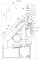
- the apparatus designated as a whole by the reference number 10, comprises a conveyor 20, which receives containers 100 to be filled in a loading station (not illustrated), supplies the containers 100 to a filling station S, and finally conveys the filled containers 100 to a further processing station (not illustrated - for example a station for closing the containers) or else a station for unloading the containers (not illustrated).
- the conveyor 20 comprises a guide 21 that extends along a closed ring-shaped path and a series of moving elements 22 that are mobile on the guide 21.
- the moving elements 22 are each provided with one or more seats 22A for housing a container 100 within each seat 22A.
- the moving elements 22 are motor-driven in an independent way so as to move on the guide 21 independently of one another.
- the conveyor 20 could be a belt conveyor with trays for housing the containers 100 or else a conveyor belt.
- the apparatus 10 comprises a dispensing unit 40 set in the filling station S.
- the dispensing unit 40 comprises one or more nozzles 42 (for example, in a number ranging from 1 to 10) for dispensing the liquid product into a corresponding number of containers 100 that are located in the filling station S.
- the nozzles 42 are constituted by dispensing needles configure to be inserted into the containers 100 for dispensing the liquid product.
- the dispensing unit 40 comprises a system for pumping the liquid product to the nozzles 42.
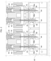
- the aforesaid pumping system may comprise plunger members 44 that are mobile with reciprocating motion within respective chambers 45 for sucking into the chambers 45 themselves the liquid product from a corresponding reservoir and expelling the liquid product out of the chambers 45 and through the nozzles 42.
- the dispensing unit 40 is of a known type, and consequently further details will not be provided herein so as not to overburden the present treatment.
- the dispensing unit 40 is vertically mobile to bring the nozzles 42 into the containers 100 to be filled.
- the dispensing unit 40 is carried by a slide that slides on a vertical guide.
- the nozzles 42 may be configure to perform a vertical movement that is independent of that of the other parts of the dispensing unit 40.
- the one or more nozzles 42 are mobile between a raised, inoperative, position (not illustrated) and a lowered position (illustrated in the figures) for dispensing the liquid product.
- the apparatus 10 comprises a tank 60, which is provided with a collection chamber 62 and with one or more inlet mouths 64 in (fluid) communication with the collection chamber 62.
- the number of inlet mouths 64 of the tank 60 is at least equal (preferably equal) to the number of nozzles 42 of the dispensing unit 40.
- the inlet mouths 64 are vertical ducts provided in one or more blocks 65 that close the top open end of the tank 60.
- the tank 60 is mobile between a resting position P1 and a working position P2, in which the inlet mouths 64 are arranged in a position underlying the nozzles 42; the tank 60 in the resting position P1 is represented schematically in Figure 1 with a dashed line.
- the nozzles 42 are lowered into their operating position, moving into the inlet mouths 64.
- the apparatus 10 comprises a control unit 80 configured for controlling movement of the tank 60 from the resting position P1 to the working position P2, and vice versa.
- control unit 80 governs movement of the tank 60 from the resting position P1 to the working position P2 as a function of a signal indicating a condition of stop of the dispensing unit 40.
- the control unit 80 itself, or a further control unit, is configured for controlling, subsequently, movement of the nozzles 62 into their lowered operating position, for example as a function of a signal that confirms positioning of the tank 60 in the working position P2.
- the tank 60 is mobile between the resting position and the working position according to a movement of translation that is preferably driven via an actuator governed by the control unit 80.
- the tank 60 is mobile between the resting position and the working position according to a movement of rototranslation that is driven via a rotary actuator 70, governed by the control unit 80.
- the tank 60 is provided with a system for blowing air comprising one or more outlets 66 for dispensing a blow of air against said one or more nozzles 42 received within the inlet mouths 64 of the tank 60.
- the aforesaid one or more outlets 66 give out into the inlet mouths 64 of the tank 60 so as to direct a blow of air against the nozzles 42 received within the inlet mouths 64 themselves.
- the blow of air is directed by the outlets 66 against the outer surface of the nozzles 42.
- any possible liquid product that might have remained stuck to the outer surface of the nozzles 42 is removed from the nozzle and pushed into the collection chamber 62 of the tank 60.
- outlets 66 are connected through a set of ducts to a common source of air under pressure (not illustrated).
- each inlet mouth 64 is defined by a vertical duct.
- the blowing system envisages for each inlet mouth 64 a pair of holes 66a that give out into said vertical duct to define said outlets 66 for dispensing a blow of air.
- said holes 66a extend towards said vertical duct in a direction inclined downwards with respect to the vertical axis of said vertical duct.
- outlets 66 are provided in a top region of the inlet mouth 64 so that the blow of air delivered by them will strike at least half of the length of the nozzle 42 inserted into a said inlet mouth 64.
- the aforesaid blow of air has the function of removing from the outer surface of the one or more nozzles any possible drops of liquid product that have stuck to the surface itself, draining them once again off into the tank 60.
- the number and position of the outlets 66 and/or the holes 66a for each inlet mouth 64 can vary with respect to what is illustrated in Figure 2 .
- the number of outlets 66 and/or holes 66a for each inlet mouth 64 may be comprised between one and six.
- the tank 60 is once again moved into the resting position P1, and the dispensing unit 40 is immediately ready to start a new cycle of dispensing of the liquid product.
- the collection chamber 62 of the tank 60 may be connected to a supply line that is to feed the liquid product to a reservoir or directly to the dispensing unit 40 so as to be able to recover the liquid product collected in the tank 60 and use it in new dispensing cycles.
- the collection chamber 62 may be manually extractable so that an operator can take out the collection chamber 62 (for example, when it is in the resting position P1) and recover the liquid product contained therein.
Landscapes
- Engineering & Computer Science (AREA)
- Mechanical Engineering (AREA)
- Supply Of Fluid Materials To The Packaging Location (AREA)
- Basic Packing Technique (AREA)
Abstract
Description
- The present invention relates to an apparatus for dispensing a liquid product into containers and a corresponding process.
- In particular, the above apparatus and the corresponding process find particular application in the sector of electronic cigarettes, in which cartridges are to be filled with a liquid product. Alternatively, the above apparatus finds application in the pharmaceutical sector, in which containers of various shapes and/or sizes are to be filled with a liquid product.
- An apparatus of a known type for dispensing a liquid product into containers comprises:
- a conveyor for conveying a plurality of containers through a filling station;
- a dispensing unit set in the filling station and comprising one or more nozzles for dispensing the liquid product into containers that follow one another in the filling station; and
- a system for pumping a liquid product to said one or more nozzles.
- A problem that afflicts apparatuses of the type referred to above regards possible dripping of the liquid product from the nozzles of the dispensing unit between one dispensing cycle and the next, in particular during unexpected interruptions of operation of the apparatus.
- The liquid product that drips from the nozzles then in fact soils the contiguous components and devices of the apparatus, for example the conveyor for conveying the containers, and may hence cause malfunctioning or jamming of the apparatus. Moreover, this calls for frequent interventions of cleaning of the apparatus. On the other hand, the liquid product lost owing to dripping is wasted and cannot be recovered.
- In this context, the present invention proposes an apparatus that is able to overcome the aforesaid drawback.
- The above object is achieved via an apparatus for dispensing a liquid product into containers according to
claim 1. - The present invention moreover relates to a process for dispensing a liquid product into containers according to
claim 10. - The claims form an integral part of the teaching provided herein.
- Further characteristics and advantages of the present invention will emerge clearly from the ensuing description with reference to the annexed drawings, which are provided purely by way of non-limiting example and in which:
-
Figure 1 illustrates an example of the apparatus forming the subject of the present invention; -
Figure 2 is a cross-sectional view of a detail of the apparatus ofFigure 1 . - In the ensuing description various specific details are illustrated, aimed at enabling an in-depth understanding of the embodiments. The embodiments may be provided without one or more of the specific details, or with other methods, components, or materials, etc. In other cases, known structures, materials, or operations are not illustrated or described in detail so that various aspects of the embodiment will not be obscured.
- The references used herein are provided merely for convenience and hence do not define the sphere of protection or the scope of the embodiments.
- As anticipated above, the apparatus described herein and forming the subject of the present invention is configured for dispensing a liquid product into containers.
- An example of application of the apparatus described herein regards filling of cartridges for electronic cigarettes. Other possible examples of application regard filling of flasks or vials or similar containers in the pharmaceutical, cosmetics, or foodstuff sectors.
- With reference to
Figure 1 , the apparatus, designated as a whole by thereference number 10, comprises aconveyor 20, which receivescontainers 100 to be filled in a loading station (not illustrated), supplies thecontainers 100 to a filling station S, and finally conveys the filledcontainers 100 to a further processing station (not illustrated - for example a station for closing the containers) or else a station for unloading the containers (not illustrated). - In one or more preferred embodiments, like the one illustrated, the
conveyor 20 comprises aguide 21 that extends along a closed ring-shaped path and a series of movingelements 22 that are mobile on theguide 21. The movingelements 22 are each provided with one ormore seats 22A for housing acontainer 100 within eachseat 22A. Preferably, the movingelements 22 are motor-driven in an independent way so as to move on theguide 21 independently of one another. - Alternatively, the
conveyor 20 could be a belt conveyor with trays for housing thecontainers 100 or else a conveyor belt. - The
apparatus 10 comprises a dispensingunit 40 set in the filling station S. The dispensingunit 40 comprises one or more nozzles 42 (for example, in a number ranging from 1 to 10) for dispensing the liquid product into a corresponding number ofcontainers 100 that are located in the filling station S. - In one or more preferred embodiments, like the one illustrated, the
nozzles 42 are constituted by dispensing needles configure to be inserted into thecontainers 100 for dispensing the liquid product. - The
dispensing unit 40 comprises a system for pumping the liquid product to thenozzles 42. With reference toFigure 2 , the aforesaid pumping system may compriseplunger members 44 that are mobile with reciprocating motion withinrespective chambers 45 for sucking into thechambers 45 themselves the liquid product from a corresponding reservoir and expelling the liquid product out of thechambers 45 and through thenozzles 42. - The dispensing
unit 40 is of a known type, and consequently further details will not be provided herein so as not to overburden the present treatment. - Preferably, the dispensing
unit 40 is vertically mobile to bring thenozzles 42 into thecontainers 100 to be filled. For instance, thedispensing unit 40 is carried by a slide that slides on a vertical guide. - Alternatively, the
nozzles 42 may be configure to perform a vertical movement that is independent of that of the other parts of thedispensing unit 40. - In general, preferably, the one or
more nozzles 42 are mobile between a raised, inoperative, position (not illustrated) and a lowered position (illustrated in the figures) for dispensing the liquid product. - According to an important characteristic of the solution described herein, the
apparatus 10 comprises atank 60, which is provided with acollection chamber 62 and with one or moreinlet mouths 64 in (fluid) communication with thecollection chamber 62. - In particular, the number of
inlet mouths 64 of thetank 60 is at least equal (preferably equal) to the number ofnozzles 42 of thedispensing unit 40. - In one or more preferred embodiments, like the one illustrated, the
inlet mouths 64 are vertical ducts provided in one ormore blocks 65 that close the top open end of thetank 60. - The
tank 60 is mobile between a resting position P1 and a working position P2, in which theinlet mouths 64 are arranged in a position underlying thenozzles 42; thetank 60 in the resting position P1 is represented schematically inFigure 1 with a dashed line. - When the
tank 60 is in the working position P2, thenozzles 42 are lowered into their operating position, moving into theinlet mouths 64. - In one or more preferred embodiments, like the one illustrated, the
apparatus 10 comprises acontrol unit 80 configured for controlling movement of thetank 60 from the resting position P1 to the working position P2, and vice versa. - In particular, the
control unit 80 governs movement of thetank 60 from the resting position P1 to the working position P2 as a function of a signal indicating a condition of stop of thedispensing unit 40. - The
control unit 80 itself, or a further control unit, is configured for controlling, subsequently, movement of thenozzles 62 into their lowered operating position, for example as a function of a signal that confirms positioning of thetank 60 in the working position P2. - According to a preferred embodiment, the
tank 60 is mobile between the resting position and the working position according to a movement of translation that is preferably driven via an actuator governed by thecontrol unit 80. - According to other embodiments, the
tank 60 is mobile between the resting position and the working position according to a movement of rototranslation that is driven via arotary actuator 70, governed by thecontrol unit 80. - In operating conditions, when the
apparatus 10 interrupts its operation, some liquid product may remain inside the one ormore nozzles 42, and/or thenozzles 42 could have already taken in the liquid product for what should have been the new dispensing cycle. Consequently, thetank 60 is moved automatically into the working position P2, thenozzles 42 come to occupy their operating position (i.e., within theinlet mouths 64 of the tank 60), and a cycle is started for dispensing the liquid product into the tank 60 (the so-called cycle of draining of the nozzles 42). Advantageously, any undesired dripping of the liquid product into the working environment is thus prevented. - In one or more preferred embodiments, like the one illustrated, the
tank 60 is provided with a system for blowing air comprising one ormore outlets 66 for dispensing a blow of air against said one ormore nozzles 42 received within theinlet mouths 64 of thetank 60. - In other words, the aforesaid one or
more outlets 66 give out into theinlet mouths 64 of thetank 60 so as to direct a blow of air against thenozzles 42 received within theinlet mouths 64 themselves. In particular, the blow of air is directed by theoutlets 66 against the outer surface of thenozzles 42. Advantageously, any possible liquid product that might have remained stuck to the outer surface of thenozzles 42 is removed from the nozzle and pushed into thecollection chamber 62 of thetank 60. - Preferably, the
outlets 66 are connected through a set of ducts to a common source of air under pressure (not illustrated). - In particular, with reference to
Figure 2 , eachinlet mouth 64 is defined by a vertical duct. - According to the preferred embodiment illustrated in
Figure 2 , the blowing system envisages for each inlet mouth 64 a pair ofholes 66a that give out into said vertical duct to define saidoutlets 66 for dispensing a blow of air. - Preferably, said
holes 66a extend towards said vertical duct in a direction inclined downwards with respect to the vertical axis of said vertical duct. - Preferably, the
outlets 66 are provided in a top region of theinlet mouth 64 so that the blow of air delivered by them will strike at least half of the length of thenozzle 42 inserted into a saidinlet mouth 64. - As has been said, the aforesaid blow of air has the function of removing from the outer surface of the one or more nozzles any possible drops of liquid product that have stuck to the surface itself, draining them once again off into the
tank 60. - It remains understood that the number and position of the
outlets 66 and/or theholes 66a for eachinlet mouth 64 can vary with respect to what is illustrated inFigure 2 . In particular, the number ofoutlets 66 and/orholes 66a for eachinlet mouth 64 may be comprised between one and six. - At the moment when operation of the
apparatus 10 resumes to fillfurther containers 100, thetank 60 is once again moved into the resting position P1, and the dispensingunit 40 is immediately ready to start a new cycle of dispensing of the liquid product. - The
collection chamber 62 of thetank 60 may be connected to a supply line that is to feed the liquid product to a reservoir or directly to the dispensingunit 40 so as to be able to recover the liquid product collected in thetank 60 and use it in new dispensing cycles. - Alternatively, the
collection chamber 62 may be manually extractable so that an operator can take out the collection chamber 62 (for example, when it is in the resting position P1) and recover the liquid product contained therein. - Of course, without prejudice to the principle of the invention, the details of construction and the embodiments may vary, even significantly, with respect to what has been illustrated purely by way of non-limiting example herein, without thereby departing from the scope of the invention, as defined by the annexed claims.
Claims (11)
- An apparatus (10) for dispensing a liquid product into containers (100), comprising:- a conveyor (20) for conveying a plurality of containers (100) through a filling station (S);- a dispensing unit (40) set in the filling station (S) and comprising one or more nozzles (42) for dispensing the liquid product into containers (100) that follow one another in the filling station (S) and a system for pumping a liquid product to said one or more nozzles (42);- a tank (60) comprising a collection chamber (62) and at least one inlet mouth (64) in communication with the collection chamber (62), said tank being mobile between a resting position (P1) and a working position (P2) in which said at least one inlet mouth (64) is set in a position underlying said one or more nozzles (42); and- a control unit (80) configured for controlling movement of said tank (60) from the resting position (P1) to the working position (P2) and vice versa, in particular as a function of a signal indicating a condition of stop of the dispensing unit (40).
- The apparatus (10) according to claim 1, wherein said control unit (80) is configured for controlling said pumping system when said tank (60) is in said working position (P2) so that said nozzles (42) can expel the liquid product into said tank (60).
- The apparatus (10) according to claim 1 or claim 2, wherein, when the tank (60) is in the working position (P2), said one or more nozzles (42) are arranged within the inlet mouth (64) of the tank and wherein said tank (60) is provided with a system for blowing air, which comprises one or more outlets (66) for dispensing a blow of air against said one or more nozzles (42) received within said inlet mouth (64).
- The apparatus (10) according to any one of the preceding claims, comprising a plurality of inlet mouths (64) for receiving, each, a respective nozzle (42) of said dispensing unit (40).
- The apparatus (10) according to claim 3 and 4, wherein each inlet mouth (64) is defined by a vertical duct and wherein a pair of holes (66a) of said air-blowing system give out into said vertical duct, preferably in opposed positions, to define said outlets (66) for dispensing a blow of air.
- The apparatus (10) according to claim 5, wherein said holes (66a) extend towards said vertical duct in a direction inclined downwards with respect to the vertical axis of said vertical duct.
- The apparatus (10) according to any one of the preceding claims, comprising an actuator (70) for driving movement of said tank between the resting position (P1) and the working position (P2).
- The apparatus (10) according to any one of the preceding claims, wherein said dispensing unit (40) or said one or more nozzles (42) is/are configured to move vertically for inserting said one or more nozzles (42) into said at least one inlet mouth (64) of the tank (60) when the latter is located in said working position (P2).
- The apparatus (10) according to any one of the preceding claims, wherein the tank (60) is mobile between the resting position (P1) and the working position (P2) according to a movement of translation.
- A process for dispensing a liquid product into containers (100), comprising:- conveying a plurality of containers (100) through a filling station (S);- by means of one or more nozzles (42) of a dispensing unit (40) that is set in the filling station (S), dispensing a liquid product into containers (100) that follow one another in the filling station (S);- providing a tank (60) comprising a collection chamber (62) and at least one inlet mouth (64) in communication with the collection chamber (62);- moving said tank (60) from a resting position (P1) to a working position (P2) in which the at least one inlet mouth (64) is set in a position underlying said one or more nozzles (42), in particular during a stop of the dispensing unit (40); and- when the tank is in the working position (P2), dispensing the liquid product contained in said one or more nozzles (42) and/or dispensing a blow of air against said one or more nozzles (42).
- The process according to claim 10, wherein the tank (60) is moved between the resting position (P1) and the working position (P2) according to a movement of translation.
Applications Claiming Priority (1)
| Application Number | Priority Date | Filing Date | Title |
|---|---|---|---|
| IT202200014119 | 2022-07-04 |
Publications (1)
| Publication Number | Publication Date |
|---|---|
| EP4303132A1 true EP4303132A1 (en) | 2024-01-10 |
Family
ID=83270746
Family Applications (1)
| Application Number | Title | Priority Date | Filing Date |
|---|---|---|---|
| EP23180366.9A Pending EP4303132A1 (en) | 2022-07-04 | 2023-06-20 | Apparatus and process for dispensing a liquid product into containers |
Country Status (2)
| Country | Link |
|---|---|
| US (1) | US12358772B2 (en) |
| EP (1) | EP4303132A1 (en) |
Citations (3)
| Publication number | Priority date | Publication date | Assignee | Title |
|---|---|---|---|---|
| US8590581B2 (en) * | 2008-04-22 | 2013-11-26 | Khs Gmbh | Method and filling system for filling bottles or similar containers with a liquid filling material and filling material dispensed into containers |
| CN110467140A (en) * | 2018-05-09 | 2019-11-19 | 张天平 | Isolated Anti-dripping device |
| CN110482460A (en) * | 2018-05-15 | 2019-11-22 | 张天平 | Isolated antidrip bottle placer |
Family Cites Families (2)
| Publication number | Priority date | Publication date | Assignee | Title |
|---|---|---|---|---|
| US3065775A (en) * | 1959-07-28 | 1962-11-27 | Diamond Crystal Salt Co | Liquid dispensing apparatus |
| US7628184B2 (en) * | 2003-11-07 | 2009-12-08 | Medical Instill Technologies, Inc. | Adjustable needle filling and laser sealing apparatus and method |
-
2023
- 2023-06-20 EP EP23180366.9A patent/EP4303132A1/en active Pending
- 2023-06-30 US US18/345,260 patent/US12358772B2/en active Active
Patent Citations (3)
| Publication number | Priority date | Publication date | Assignee | Title |
|---|---|---|---|---|
| US8590581B2 (en) * | 2008-04-22 | 2013-11-26 | Khs Gmbh | Method and filling system for filling bottles or similar containers with a liquid filling material and filling material dispensed into containers |
| CN110467140A (en) * | 2018-05-09 | 2019-11-19 | 张天平 | Isolated Anti-dripping device |
| CN110482460A (en) * | 2018-05-15 | 2019-11-22 | 张天平 | Isolated antidrip bottle placer |
Also Published As
| Publication number | Publication date |
|---|---|
| US12358772B2 (en) | 2025-07-15 |
| US20240002206A1 (en) | 2024-01-04 |
Similar Documents
| Publication | Publication Date | Title |
|---|---|---|
| JP6918585B2 (en) | Automatic packaging machine for filling a certain amount of fluidized products in bags made of heat-sealable material | |
| US4640322A (en) | Method and apparatus for filling a receptacle with a material | |
| RU2369556C2 (en) | Device for changing tools set at container treating rotating machines | |
| CN101534968B (en) | Spraying station of a cleaning machine for bottles or similar containers, and cleaning machine comprising at least one spraying station | |
| EP2821149A1 (en) | Apparatus and system for the external cleaning of containers for loose substances | |
| CN106660647B (en) | Unit and method for filling a container forming a single-use capsule for extracting or infusion beverages | |
| KR20190115807A (en) | Rotary type automatic packaging system that can supply filling quantity | |
| US7011117B1 (en) | Filling valve | |
| US8434530B2 (en) | Filler valve unit | |
| US12358772B2 (en) | Apparatus and process for dispensing a liquid product into containers | |
| EP3755629B1 (en) | Apparatus for filling containers with dosed quantities of powdered material | |
| CN108437408B (en) | Internal dusting device and dusting method for at least one preform | |
| US11148157B2 (en) | Apparatus for coating bulk material | |
| JP7167497B2 (en) | container handling system | |
| JPS62158628A (en) | Device for filling vessel with substance | |
| EP3747561B1 (en) | Washing machine for containers, in particular for products of the pharmaceutical industry | |
| KR20050027273A (en) | A capsule filling machine | |
| CN109080865B (en) | dropper | |
| US3321887A (en) | Method and apparatus for adding liquid fill to containers having solids therein | |
| WO2015170198A1 (en) | A method for coating an inner wall of a container | |
| EP4335561B1 (en) | Rinsing machine for bottles and method for rinsing bottles | |
| CN111771944B (en) | Beef cattle slaughtering line | |
| JP2005334546A (en) | Cleaning device of vibration feeder in packing machine | |
| EP3747828A1 (en) | Device for applying caps | |
| KR200467407Y1 (en) | Apparatus for eliminating foreign substance in container |
Legal Events
| Date | Code | Title | Description |
|---|---|---|---|
| PUAI | Public reference made under article 153(3) epc to a published international application that has entered the european phase |
Free format text: ORIGINAL CODE: 0009012 |
|
| STAA | Information on the status of an ep patent application or granted ep patent |
Free format text: STATUS: THE APPLICATION HAS BEEN PUBLISHED |
|
| AK | Designated contracting states |
Kind code of ref document: A1 Designated state(s): AL AT BE BG CH CY CZ DE DK EE ES FI FR GB GR HR HU IE IS IT LI LT LU LV MC ME MK MT NL NO PL PT RO RS SE SI SK SM TR |
|
| STAA | Information on the status of an ep patent application or granted ep patent |
Free format text: STATUS: REQUEST FOR EXAMINATION WAS MADE |
|
| 17P | Request for examination filed |
Effective date: 20240320 |
|
| RBV | Designated contracting states (corrected) |
Designated state(s): AL AT BE BG CH CY CZ DE DK EE ES FI FR GB GR HR HU IE IS IT LI LT LU LV MC ME MK MT NL NO PL PT RO RS SE SI SK SM TR |
|
| P01 | Opt-out of the competence of the unified patent court (upc) registered |
Effective date: 20240522 |