EP4303130A1 - Uav docking station and uav assembly - Google Patents
Uav docking station and uav assembly Download PDFInfo
- Publication number
- EP4303130A1 EP4303130A1 EP23183913.5A EP23183913A EP4303130A1 EP 4303130 A1 EP4303130 A1 EP 4303130A1 EP 23183913 A EP23183913 A EP 23183913A EP 4303130 A1 EP4303130 A1 EP 4303130A1
- Authority
- EP
- European Patent Office
- Prior art keywords
- uav
- docking station
- housing
- accommodation cavity
- cavity
- Prior art date
- Legal status (The legal status is an assumption and is not a legal conclusion. Google has not performed a legal analysis and makes no representation as to the accuracy of the status listed.)
- Pending
Links
Images


Classifications
-
- B—PERFORMING OPERATIONS; TRANSPORTING
- B64—AIRCRAFT; AVIATION; COSMONAUTICS
- B64U—UNMANNED AERIAL VEHICLES [UAV]; EQUIPMENT THEREFOR
- B64U70/00—Launching, take-off or landing arrangements
- B64U70/90—Launching from or landing on platforms
-
- B—PERFORMING OPERATIONS; TRANSPORTING
- B64—AIRCRAFT; AVIATION; COSMONAUTICS
- B64U—UNMANNED AERIAL VEHICLES [UAV]; EQUIPMENT THEREFOR
- B64U70/00—Launching, take-off or landing arrangements
- B64U70/90—Launching from or landing on platforms
- B64U70/92—Portable platforms
-
- B—PERFORMING OPERATIONS; TRANSPORTING
- B64—AIRCRAFT; AVIATION; COSMONAUTICS
- B64F—GROUND OR AIRCRAFT-CARRIER-DECK INSTALLATIONS SPECIALLY ADAPTED FOR USE IN CONNECTION WITH AIRCRAFT; DESIGNING, MANUFACTURING, ASSEMBLING, CLEANING, MAINTAINING OR REPAIRING AIRCRAFT, NOT OTHERWISE PROVIDED FOR; HANDLING, TRANSPORTING, TESTING OR INSPECTING AIRCRAFT COMPONENTS, NOT OTHERWISE PROVIDED FOR
- B64F1/00—Ground or aircraft-carrier-deck installations
- B64F1/22—Ground or aircraft-carrier-deck installations for handling aircraft
- B64F1/222—Ground or aircraft-carrier-deck installations for handling aircraft for storing aircraft, e.g. in hangars
-
- B—PERFORMING OPERATIONS; TRANSPORTING
- B64—AIRCRAFT; AVIATION; COSMONAUTICS
- B64U—UNMANNED AERIAL VEHICLES [UAV]; EQUIPMENT THEREFOR
- B64U80/00—Transport or storage specially adapted for UAVs
- B64U80/10—Transport or storage specially adapted for UAVs with means for moving the UAV to a supply or launch location, e.g. robotic arms or carousels
-
- B—PERFORMING OPERATIONS; TRANSPORTING
- B64—AIRCRAFT; AVIATION; COSMONAUTICS
- B64U—UNMANNED AERIAL VEHICLES [UAV]; EQUIPMENT THEREFOR
- B64U10/00—Type of UAV
- B64U10/20—Vertical take-off and landing [VTOL] aircraft
Definitions
- the embodiments of the present disclosure relate to the technical field of unmanned aerial vehicles (UAVs), and particularly relate to an unmanned aerial vehicle (UAV) docking station and an UAV assembly.
- UAVs unmanned aerial vehicles
- UAV unmanned aerial vehicle
- Unmanned aerial vehicle has the advantages of small volume, easy control and so on. From cable inspection, ecological environment monitoring to emergency site command, the unmanned aerial vehicle has been widely used in more and more fields and can undertake more and more tasks.
- the technical problem to be mainly solved by the embodiments of the present disclosure is to provide an unmanned aerial vehicle (UAV) docking station and an UAV assembly, which can reduce the volume and weight of the UAV docking station.
- UAV unmanned aerial vehicle
- one embodiment of the present disclosure provides an UAV docking station.
- the UAV docking station includes:
- the extension piece is integrally formed with the housing.
- the extension piece is removably connected to the housing.
- the UAV docking station further includes a first drive mechanism disposed within the accommodation cavity and connected to the door, the first drive mechanism being used for driving the door to open or close the hatch.
- the door is rotatably connected to the housing, and the first drive mechanism comprises a first drive motor and a first connector, the first drive motor being provided in the accommodation cavity, the first drive motor being connected to one end of the first connector, and the other end of the first connector being connected to the door.
- the UAV docking station further includes a parking apron disposed within the accommodation cavity.
- the UAV docking station further includes a parking apron and a second drive mechanism, the second drive mechanism being disposed in the accommodation cavity, the parking apron being connected to the second drive mechanism, the second drive mechanism being capable of driving the parking apron out of the housing from the accommodation cavity or driving the parking apron into the accommodation cavity from outside the housing.
- the second drive mechanism includes a second drive motor, a second connector and a guide rail, the second drive motor and the guide rail being both arranged in the accommodation cavity, the second connector being movably arranged on the guide rail, the second drive motor being connected to the second connector, and the parking apron being fixed to the second connector; and the second connector is movable along the guide rail upon driving by the second drive motor.
- UAV assembly includes the UAV docking station according to any of the above-mentioned embodiments.
- the cross-sectional area where the extension cavity communicates with the accommodation cavity is greater than the cross-sectional area of the accommodation cavity, so that the UAV docking station can accommodate an UAV in a smaller volume.
- UAVs unmanned aerial vehicles
- the types of UAVs include multi-rotor foldable UAVs and fixed-wing UAVs.
- the ulti-rotor foldable UAV relies on the lift generated by multiple rotors to balance the gravity of the UAV, so that the UAV can fly up, by changing the speed of each rotor to control the stability and attitude of the UAV.
- the ulti-rotor foldable UAV can hover and fly at any speed in a certain speed range.
- the fixed-wing UAV relies on the thrust generated by propeller as the power of forward flight of the UAV. The main lift comes from the relative motion between the fixed wing and air.
- fixed-wing UAV must have a certain relative velocity without air to have lift to fly. Based on this principle, fixed-wing UAV has the characteristics of fast flight speed, relative economy, large carrying capacity and strong endurance. Since the wing of a fixed-wing UAV is not foldable, the UAV docking station for accommodating the fixed-wing UAV is generally large in its entirety, thereby allowing the accommodation cavity of the UAV docking station to accommodate the fixed wing of the UAV. In order to reduce the volume of the UAV docking station accommodating the fixed-wing UAV and reduce the weight of the UAV docking station, the present disclosure provides an embodiment of the UAV docking station.
- an unmanned aerial vehicle (UAV) docking station 1 comprises a housing 10, an extension piece 20 and a door 30, wherein the housing 10 is provided with an accommodation cavity 101 and a hatch 102 communicating with the accommodation cavity 101, the extension piece 20 is provided with an extension cavity 201, the extension piece 20 is connected to the housing 10, the extension piece 20 is provided on a side portion on one end, near the hatch 102, of the housing 10, the extension cavity 201 communicates with the accommodation cavity 101, and a cross-sectional area where the extension cavity 201 communicates with the accommodation chamber 101 is greater than a cross-sectional area of the accommodation chamber 101, the door 30 is connected to the housing 10, and the door 30 is provided at the hatch 102 and the door 30 is capable of opening or closing the hatch 102.
- UAV unmanned aerial vehicle
- a fixed-wing part of the UAV is accommodated in the accommodation cavity 101, and a rear half part, near a tail part, of the fixed wing of the UAV can be accommodated in the extension cavity 201 of the extension piece 20.
- the extension piece 20 is arranged at one end, near the door 30, of the housing 10 and the extension piece 20 extends towards an outside of the housing 10, only the cross-sectional area of the part near the door 30 of the UAV docking station 1 is larger, namely, a volume of an end near the door 30 is larger, and the volume of the UAV docking station 1 at the part away from the door 30 can be reduced.
- the reduction in volume of the UAV docking station 1 improves the overall weight of the UAV docking station 1, making the UAV docking station 1 lighter.
- a number of the extension pieces 20 is at least two, and two of the extension pieces 20 are symmetrically arranged at both sides of the housing 10.
- the symmetrical arrangement of the extension pieces 20 improves the stability of the UAV docking station 1.
- the extension piece 20 is integrally formed with the housing 10.
- the extension piece 20 is detachably connected to the housing 10, wherein the number of the extension pieces 20 is set as two in a group as an extension portion, the extension portions are provided in a plurality, and the structure and shape of the extension pieces 20 of the plurality of the extension portions are different.
- the present embodiment exemplifies one of the structures and profiles of the extension piece 20.
- the housing 10 in order to facilitate the transport and transfer of the UAV docking station 1, is provided with a traction element 11, which is capable of facilitating the transfer of the UAV docking station 1 by a transfer mechanism by grasping the traction element 11 during the production and preparation of the UAV docking station 1.
- the UAV docking station 1 further comprises a first drive mechanism 40 disposed within the accommodation cavity 101 and connected to the door 30, the first drive mechanism 40 being used for driving the door 30 to open or close the hatch 102.
- the door 30 is rotatably connected to the housing 10, and the first drive mechanism 40 comprises a first drive motor 401, a first telescopic rod 402 and a first connector 403, wherein the first drive motor 401 is arranged in the accommodation cavity 101, one end of the first telescopic rod 402 is connected to the first drive motor 401, the other end of the first telescopic rod 402 is rotatably connected to one end of the first connector 403, and the other end of the first connector 403 is rotatably connected to the door 30.
- the first drive mechanism 40 comprises a first drive motor 401, a first telescopic rod 402 and a first connector 403, wherein the first drive motor 401 is arranged in the accommodation cavity 101, one end of the first telescopic rod 402 is connected to the first drive motor 401, the other end of the first telescopic rod 402 is rotatably connected to one end of the first connector 403, and the other end of the first connector 403 is rotatably connected to the door 30.
- the first drive motor 401 drives the telescopic rod to extend, and the telescopic rod drives the first connector 403 to push the door 30, so that the door 30 rotates relatively to the housing 10 to complete the door 30 opening the hatch 102.
- the first drive motor 401 drives the telescopic rod to contract, and the telescopic rod drives the first connector 403 to pull the door 30, so that the door 30 rotates relatively to the housing 10 until the hatch 102 is covered.
- the UAV docking station 1 further comprises a parking apron 50 disposed within the accommodation cavity 101.
- the parking apron 50 is used to park the UAV.
- the UAV docking station 1 further comprises a second drive mechanism 60, which is connected to the parking apron 50 and which is capable of driving the parking apron 50 out of or into the accommodation chamber 101.
- the second drive mechanism 60 comprises a second drive motor 601, a second telescopic rod 602, a second connector 603 and a guide rail 604, the second drive motor 601 and the guide rail 604 are both arranged in the accommodation cavity 101, one end of the second telescopic rod 602 is connected to the second drive motor 601, the other end of the second telescopic rod 602 is connected to the second connector 603, the second connector 603 is movably arranged on the guide rail 604, and the parking apron 50 is fixed with the second connector 603.
- the second connector 603 is movable along the guide rail 604 upon driving by the second drive motor 601.
- the door 30 is opened, the second drive motor 601 drives the second telescopic rod 602 to extend, and the second telescopic rod 602 drives the second connector 603 to slide on the guide rail 604, so that the parking apron 50 gradually extends out of the hatch 102 from the accommodation cavity 101 and is exposed to the outside of the UAV docking station 1.
- the second drive motor 601 drives the second telescopic rod 602 to contract, and the second telescopic rod 602 drives the second connector 603 to slide on the guide rail 604, so that the parking apron 50 gradually enters the accommodation cavity 101 from the outside of the UAV docking station 1, and then the hatch door 30 closes the hatch 102.
- the UAV docking station is further provided with a caster 90.
- the cross-sectional area where the extension cavity 201 communicates with the accommodation cavity 101 is greater than the cross-sectional area of the accommodation cavity 101, so that the UAV docking station 1 can accommodate an UAV in a smaller volume.
- the present disclosure further provides an embodiment of an UAV assembly 100, wherein the UAV assembly 100 comprises the UAV docking station 1 according to any one of the above-mentioned embodiments and an UAV 2, wherein the UAV 2 is accommodated in the accommodation cavity 101 of the UAV docking station 1, and a fixed wing of the UAV 2 is accommodated in the extension cavity 201.
- the UAV docking station 1 The structure and function of the UAV docking station 1 are described with reference to the above-mentioned embodiments, and will not be described in detail herein.
Landscapes
- Engineering & Computer Science (AREA)
- Aviation & Aerospace Engineering (AREA)
- Remote Sensing (AREA)
- Mechanical Engineering (AREA)
- Robotics (AREA)
- Transportation (AREA)
- Power-Operated Mechanisms For Wings (AREA)
- Forklifts And Lifting Vehicles (AREA)
Abstract
An unmanned aerial vehicle (UAV) assembly includes an UAV and an UAV docking station (1). The UAV docking station includes a housing (10), an extension piece (20), and a door (30). The housing is provided with an accommodation cavity (101) and a hatch (102) communicating with the accommodation cavity. The extension piece is provided with an extension cavity (201) and connected to the housing. The extension piece is provided on a side portion on one end, near the hatch (102), of the housing (10), and the extension cavity communicates with the accommodation cavity (101). The door (30) is connected to the housing and provided at the hatch (102), and the door is capable of opening or closing the hatch. A cross-sectional area where the extension cavity communicates with the accommodation cavity being greater than a cross-sectional area of the accommodation cavity. The UAV can be accommodated in the accommodation cavity (101) of the UAV docking station (1).
Description
- The embodiments of the present disclosure relate to the technical field of unmanned aerial vehicles (UAVs), and particularly relate to an unmanned aerial vehicle (UAV) docking station and an UAV assembly.
- Unmanned aerial vehicle (UAV) has the advantages of small volume, easy control and so on. From cable inspection, ecological environment monitoring to emergency site command, the unmanned aerial vehicle has been widely used in more and more fields and can undertake more and more tasks.
- At present, the price of UAVs is still relatively high, belonging to the more expensive items. In order to better preserve the UAV increase its endurance, the UAV is usually equipped with a special UAV docking station, and the UAV is taken out from the UAV docking station when it is used, or the UAV needs to return to the UAV docking station for power exchange because of insufficient power in the process of operation. However, the inventor of the present disclosure has found that the UAV docking station for accommodating the fixed-wing UAV is relatively large, and the relatively large volume makes the weight of the UAV docking station relatively large, which is not conducive to movement.
- The technical problem to be mainly solved by the embodiments of the present disclosure is to provide an unmanned aerial vehicle (UAV) docking station and an UAV assembly, which can reduce the volume and weight of the UAV docking station.
- In a first aspect, one embodiment of the present disclosure provides an UAV docking station. The UAV docking station includes:
- a housing provided with an accommodation cavity and a hatch communicating with the accommodation cavity;
- an extension piece provided with an extension cavity, the extension piece being connected to the housing, the extension piece being provided on a side portion on one end, near the hatch, of the housing, the extension cavity communicating with the accommodation cavity;
- a door provided at the hatch, the door being capable of opening or closing the hatch;
- a cross-sectional area where the extension cavity communicates with the accommodation cavity being greater than a cross-sectional area of the accommodation cavity.
- In one embodiment, a number of the extension pieces is at least two, and two of the extension pieces are symmetrically arranged at both sides of the housing.
- The extension piece is integrally formed with the housing.
- The extension piece is removably connected to the housing.
- The UAV docking station further includes a first drive mechanism disposed within the accommodation cavity and connected to the door, the first drive mechanism being used for driving the door to open or close the hatch.
- The door is rotatably connected to the housing, and the first drive mechanism comprises a first drive motor and a first connector, the first drive motor being provided in the accommodation cavity, the first drive motor being connected to one end of the first connector, and the other end of the first connector being connected to the door.
- The UAV docking station further includes a parking apron disposed within the accommodation cavity.
- The UAV docking station further includes a parking apron and a second drive mechanism, the second drive mechanism being disposed in the accommodation cavity, the parking apron being connected to the second drive mechanism, the second drive mechanism being capable of driving the parking apron out of the housing from the accommodation cavity or driving the parking apron into the accommodation cavity from outside the housing.
- The second drive mechanism includes a second drive motor, a second connector and a guide rail, the second drive motor and the guide rail being both arranged in the accommodation cavity, the second connector being movably arranged on the guide rail, the second drive motor being connected to the second connector, and the parking apron being fixed to the second connector; and
the second connector is movable along the guide rail upon driving by the second drive motor. - In a second aspect, another embodiment of the present disclosure provides an UAV assembly. The UAV assembly includes the UAV docking station according to any of the above-mentioned embodiments; and
- an UAV, the UAV being able to be accommodated in the accommodation cavity of the UAV docking station;
- a fuselage of the UAV being accommodated in the accommodation cavity, and a fixed wing of the UAV being accommodated in the extension cavity.
- In the embodiments of the present disclosure, by providing an extension piece on the housing, and allowing the extension cavity of the extension piece to communicate with the accommodation cavity of the housing, the cross-sectional area where the extension cavity communicates with the accommodation cavity is greater than the cross-sectional area of the accommodation cavity, so that the UAV docking station can accommodate an UAV in a smaller volume.
-
-
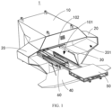
FIG. 1 is an overall schematic diagram of an embodiment of the unmanned aerial vehicle (UAV) docking station of the present disclosure; -
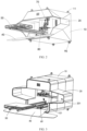
FIG. 2 is a schematic diagram from another perspective view of the embodiment of the UAV docking station of the present disclosure; -
FIG. 3 is a schematic diagram of another embodiment of the present UAV docking station of the disclosure; -
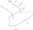
FIG. 4 is a schematic diagram of a first drive mechanism of an embodiment of the UAV docking station of the present disclosure; -
FIG. 5 is a schematic diagram of a second drive mechanism of an embodiment of the UAV docking station of the present disclosure; -
FIG. 6 is a schematic diagram of an embodiment of an UAV assembly of the present disclosure. - In order to facilitate an understanding of the present disclosure, a more detailed description of the disclosure is provided below in connection with the accompanying drawings and specific embodiments. It will be understood that when an element is referred to as being "fixed" to another element, it can be directly on the other element or intervening elements may be present. When an element is referred to as being "connected" to another element, it can be directly connected to the other element or intervening elements may be present. The terms "vertical", "horizontal", "left", "right", and the like are used herein for descriptive purposes only.
- Unless otherwise defined, all technical and scientific terms used herein have the same meaning as commonly understood by one of ordinary skill in the art to which the present disclosure belongs. The terminology used in the description of the present disclosure herein is for the purpose of describing particular embodiments only and is not intended to be limiting of the disclosure. As used herein, the term "and/or" includes any and all combinations of one or more of the associated listed items.
- With the rise of intelligent unmanned equipment, in the technical field of unmanned aerial vehicles (UAVs), the types of UAVs include multi-rotor foldable UAVs and fixed-wing UAVs. The ulti-rotor foldable UAV relies on the lift generated by multiple rotors to balance the gravity of the UAV, so that the UAV can fly up, by changing the speed of each rotor to control the stability and attitude of the UAV. The ulti-rotor foldable UAV can hover and fly at any speed in a certain speed range. The fixed-wing UAV relies on the thrust generated by propeller as the power of forward flight of the UAV. The main lift comes from the relative motion between the fixed wing and air. Therefore, fixed-wing UAV must have a certain relative velocity without air to have lift to fly. Based on this principle, fixed-wing UAV has the characteristics of fast flight speed, relative economy, large carrying capacity and strong endurance. Since the wing of a fixed-wing UAV is not foldable, the UAV docking station for accommodating the fixed-wing UAV is generally large in its entirety, thereby allowing the accommodation cavity of the UAV docking station to accommodate the fixed wing of the UAV. In order to reduce the volume of the UAV docking station accommodating the fixed-wing UAV and reduce the weight of the UAV docking station, the present disclosure provides an embodiment of the UAV docking station.
- With reference to
FIG. 1 andFIG. 2 , an unmanned aerial vehicle (UAV)docking station 1 comprises ahousing 10, anextension piece 20 and adoor 30, wherein thehousing 10 is provided with anaccommodation cavity 101 and ahatch 102 communicating with theaccommodation cavity 101, theextension piece 20 is provided with anextension cavity 201, theextension piece 20 is connected to thehousing 10, theextension piece 20 is provided on a side portion on one end, near thehatch 102, of thehousing 10, theextension cavity 201 communicates with theaccommodation cavity 101, and a cross-sectional area where theextension cavity 201 communicates with theaccommodation chamber 101 is greater than a cross-sectional area of theaccommodation chamber 101, thedoor 30 is connected to thehousing 10, and thedoor 30 is provided at thehatch 102 and thedoor 30 is capable of opening or closing thehatch 102. When the UAV is accommodated in theUAV docking station 1, a fixed-wing part of the UAV is accommodated in theaccommodation cavity 101, and a rear half part, near a tail part, of the fixed wing of the UAV can be accommodated in theextension cavity 201 of theextension piece 20. Since theextension piece 20 is arranged at one end, near thedoor 30, of thehousing 10 and theextension piece 20 extends towards an outside of thehousing 10, only the cross-sectional area of the part near thedoor 30 of theUAV docking station 1 is larger, namely, a volume of an end near thedoor 30 is larger, and the volume of theUAV docking station 1 at the part away from thedoor 30 can be reduced. The reduction in volume of theUAV docking station 1 improves the overall weight of theUAV docking station 1, making theUAV docking station 1 lighter. - In the embodiment of the present disclosure, a number of the
extension pieces 20 is at least two, and two of theextension pieces 20 are symmetrically arranged at both sides of thehousing 10. The symmetrical arrangement of theextension pieces 20 improves the stability of theUAV docking station 1. - In some embodiments, the
extension piece 20 is integrally formed with thehousing 10. - In other embodiments, since the models of fixed-wing UAVs are different, and wing lengths of the fixed wings are different between different models of fixed-wing UAVs, an UAV with a longer fixed wing requires a larger space of the
extension cavity 201 of the UAV docking station, and an UAV with a shorter fixed wing can allow the space of theextension cavity 201 to be smaller, so that in order to be able to adapt to more types of fixed-wing UAVs by freely changing theextension cavity 201 of theUAV docking station 1, theextension piece 20 is detachably connected to thehousing 10, wherein the number of theextension pieces 20 is set as two in a group as an extension portion, the extension portions are provided in a plurality, and the structure and shape of theextension pieces 20 of the plurality of the extension portions are different. With reference toFIG. 3 , illustratively, the present embodiment exemplifies one of the structures and profiles of theextension piece 20. - In some embodiments, in order to facilitate the transport and transfer of the
UAV docking station 1, thehousing 10 is provided with atraction element 11, which is capable of facilitating the transfer of theUAV docking station 1 by a transfer mechanism by grasping thetraction element 11 during the production and preparation of theUAV docking station 1. - With reference to
FIG. 4 , in the embodiment of the present disclosure, theUAV docking station 1 further comprises afirst drive mechanism 40 disposed within theaccommodation cavity 101 and connected to thedoor 30, thefirst drive mechanism 40 being used for driving thedoor 30 to open or close thehatch 102. - Specifically, the
door 30 is rotatably connected to thehousing 10, and thefirst drive mechanism 40 comprises a first drive motor 401, a first telescopic rod 402 and a first connector 403, wherein the first drive motor 401 is arranged in theaccommodation cavity 101, one end of the first telescopic rod 402 is connected to the first drive motor 401, the other end of the first telescopic rod 402 is rotatably connected to one end of the first connector 403, and the other end of the first connector 403 is rotatably connected to thedoor 30. When thedoor 30 needs to open thehatch 102 of thehousing 10, the first drive motor 401 drives the telescopic rod to extend, and the telescopic rod drives the first connector 403 to push thedoor 30, so that thedoor 30 rotates relatively to thehousing 10 to complete thedoor 30 opening thehatch 102. When thehatch 102 needs to be closed, the first drive motor 401 drives the telescopic rod to contract, and the telescopic rod drives the first connector 403 to pull thedoor 30, so that thedoor 30 rotates relatively to thehousing 10 until thehatch 102 is covered. - In the embodiment of the present disclosure, the
UAV docking station 1 further comprises aparking apron 50 disposed within theaccommodation cavity 101. Theparking apron 50 is used to park the UAV. - Further, with reference to
FIG. 5 , theUAV docking station 1 further comprises asecond drive mechanism 60, which is connected to theparking apron 50 and which is capable of driving theparking apron 50 out of or into theaccommodation chamber 101. - Specifically, the
second drive mechanism 60 comprises asecond drive motor 601, a secondtelescopic rod 602, asecond connector 603 and aguide rail 604, thesecond drive motor 601 and theguide rail 604 are both arranged in theaccommodation cavity 101, one end of the secondtelescopic rod 602 is connected to thesecond drive motor 601, the other end of the secondtelescopic rod 602 is connected to thesecond connector 603, thesecond connector 603 is movably arranged on theguide rail 604, and theparking apron 50 is fixed with thesecond connector 603. Thesecond connector 603 is movable along theguide rail 604 upon driving by thesecond drive motor 601. When theUAV docking station 1 accommodating the UAV needs the UAV to go out for operation, or when theUAV docking station 1 which is empty needs to accommodate the UAV to go home, thedoor 30 is opened, thesecond drive motor 601 drives the secondtelescopic rod 602 to extend, and the secondtelescopic rod 602 drives thesecond connector 603 to slide on theguide rail 604, so that theparking apron 50 gradually extends out of thehatch 102 from theaccommodation cavity 101 and is exposed to the outside of theUAV docking station 1. When the UAV needs to be accommodated in theaccommodation cavity 101 by theUAV docking station 1 after the UAV stops at theparking apron 50, thesecond drive motor 601 drives the secondtelescopic rod 602 to contract, and the secondtelescopic rod 602 drives thesecond connector 603 to slide on theguide rail 604, so that theparking apron 50 gradually enters theaccommodation cavity 101 from the outside of theUAV docking station 1, and then thehatch door 30 closes thehatch 102. - In some other embodiments, to facilitate movement of the
UAV docking station 1, the UAV docking station is further provided with acaster 90. - In the embodiment of the present disclosure, by providing an
extension piece 20 on the housing, and allowing theextension cavity 201 of theextension piece 20 to communicate with theaccommodation cavity 101 of thehousing 10, the cross-sectional area where theextension cavity 201 communicates with theaccommodation cavity 101 is greater than the cross-sectional area of theaccommodation cavity 101, so that theUAV docking station 1 can accommodate an UAV in a smaller volume. - With reference to
FIG. 6 , the present disclosure further provides an embodiment of anUAV assembly 100, wherein theUAV assembly 100 comprises theUAV docking station 1 according to any one of the above-mentioned embodiments and anUAV 2, wherein theUAV 2 is accommodated in theaccommodation cavity 101 of theUAV docking station 1, and a fixed wing of theUAV 2 is accommodated in theextension cavity 201. The structure and function of theUAV docking station 1 are described with reference to the above-mentioned embodiments, and will not be described in detail herein. - It should be noted that the description of the present disclosure and the drawings thereof provide preferred embodiments of the present disclosure. However, the present disclosure can be realized in many different forms and is not limited to the embodiments described in the description, and these embodiments are not provided as additional limitations on the contents of the present disclosure, but these embodiments are provided such that the content disclosed in the present disclosure can be more fully and thoroughly understood from the disclosure. Furthermore, the above-mentioned technical features continue to be combined with each other to form various embodiments which are not listed above, and all are considered to be within the scope of the description of the present disclosure. Further, those skilled in the art will be able to make improvements or modifications in light of the foregoing teachings, and all such improvements and modifications are intended to fall within the scope of protection of the appended claims of the present disclosure.
Claims (10)
- An unmanned aerial vehicle (UAV) docking station (1), characterized by comprising:a housing (10) provided with an accommodation cavity (101) and a hatch (102) communicating with the accommodation cavity (101);an extension piece (20) provided with an extension cavity (201), the extension piece (20) being connected to the housing (10), the extension piece (20) being provided on a side portion on one end, near the hatch (102), of the housing (10), and the extension cavity (201) communicating with the accommodation cavity (101);a door (30) connected to the housing (10), the door (30) being provided at the hatch (102) and the door (30) being capable of opening or closing the hatch (102);a cross-sectional area where the extension cavity (201) communicates with the accommodation cavity (101) being greater than a cross-sectional area of the accommodation cavity (101).
- The UAV docking station (1) according to claim 1, characterized in that a number of the extension pieces (20) is at least two, and two of the extension pieces (20) are symmetrically arranged at both sides of the housing (10).
- The UAV docking station (1) according to claim 2, characterized in that the extension piece (20) is integrally formed with the housing (10).
- The UAV docking station (1) according to claim 2, characterized in that the extension piece (20) is removably connected to the housing (10).
- The UAV docking station (1) according to claim 1, further characterized by comprising a first drive mechanism (40) disposed within the accommodation cavity (101) and connected to the door (30), the first drive mechanism (40) being used for driving the door (30) to open or close the hatch (102).
- The UAV docking station (1) according to claim 5, characterized in that the door (30) is rotatably connected to the housing (10), and the first drive mechanism (40) comprises a first drive motor (401) and a first connector (403), the first drive motor(401) being provided in the accommodation cavity (101), the first drive motor(401) being connected to one end of the first connector (403), and the other end of the first connector (403) being connected to the door (30).
- The UAV docking station (1) according to claim 6, further characterized by comprising a parking apron (50) disposed within the accommodation cavity (101).
- The UAV docking station (1) according to claim 6, further comprising a parking apron (50) and a second drive mechanism (60), the second drive mechanism (60) being disposed in the accommodation cavity (101), the parking apron (50) being connected to the second drive mechanism (60), the second drive mechanism (60) being capable of driving the parking apron (50) out of the housing (10) from the accommodation cavity (101) or driving the parking apron (50) into the accommodation cavity (101) from outside the housing (10).
- The UAV docking station (1) according to claim 8, characterized in that the second drive mechanism (60) comprises a second drive motor (601), a second connector (603) and a guide rail (604), the second drive motor (601) and the guide rail (604) being both arranged in the accommodation cavity (101), the second connector (603) being movably arranged on the guide rail (604), the second drive motor (601) being connected to the second connector (603), and the parking apron (50) being fixed to the second connector (603);
the second connector (603) is movable along the guide rail (604) upon driving by the second drive motor (601). - An unmanned aerial vehicle (UAV) assembly, characterized by comprising:the UAV docking station (1) according to any one of claims 1-9; andan UAV, the UAV being able to be accommodated in the accommodation cavity (101) of the UAV docking station (1);a fuselage of the UAV being accommodated in the accommodation cavity (101), and a fixed wing of the UAV being accommodated in the extension cavity (201).
Applications Claiming Priority (1)
| Application Number | Priority Date | Filing Date | Title |
|---|---|---|---|
| CN202221744664.5U CN217918468U (en) | 2022-07-06 | 2022-07-06 | Machine nest and unmanned aerial vehicle subassembly |
Publications (1)
| Publication Number | Publication Date |
|---|---|
| EP4303130A1 true EP4303130A1 (en) | 2024-01-10 |
Family
ID=84187335
Family Applications (1)
| Application Number | Title | Priority Date | Filing Date |
|---|---|---|---|
| EP23183913.5A Pending EP4303130A1 (en) | 2022-07-06 | 2023-07-06 | Uav docking station and uav assembly |
Country Status (3)
| Country | Link |
|---|---|
| US (1) | US12162634B2 (en) |
| EP (1) | EP4303130A1 (en) |
| CN (1) | CN217918468U (en) |
Families Citing this family (10)
| Publication number | Priority date | Publication date | Assignee | Title |
|---|---|---|---|---|
| WO2024118965A1 (en) * | 2022-12-01 | 2024-06-06 | Johnson Kara E | Aircraft takeoff and landing apparatus |
| US12572153B1 (en) | 2022-12-15 | 2026-03-10 | Amazon Technologies, Inc. | Route planning for aerial vehicles in indoor spaces |
| USD1118461S1 (en) * | 2022-12-30 | 2026-03-17 | Autel Robotics Co., Ltd. | Nest |
| USD1032432S1 (en) * | 2023-01-04 | 2024-06-25 | Autel Robotics Co., Ltd. | Storage unit for unmanned aerial vehicles |
| US20240391616A1 (en) * | 2023-01-13 | 2024-11-28 | Easy Aerial Inc. | Unmanned aerial vehicle system including foldable unmanned aerial vehicle |
| US12528608B1 (en) * | 2024-03-18 | 2026-01-20 | Amazon Technologies, Inc. | Docking stations for safely charging aerial vehicles |
| US12344411B1 (en) * | 2024-04-03 | 2025-07-01 | Hoodman Corporation | Foldable launch and landing pad for drones |
| US12545447B1 (en) * | 2024-06-07 | 2026-02-10 | Amazon Technologies, Inc. | Aerial vehicle landing pad with sensors |
| US20260048866A1 (en) * | 2024-08-15 | 2026-02-19 | Skydio, Inc. | Landing platform in a base station for use with unmanned aerial vehicles and including drive brackets |
| US20260048877A1 (en) * | 2024-08-15 | 2026-02-19 | Skydio, Inc. | Base Station For An Unmanned Aerial Vehicle Including A Rotatable Roof Assembly |
Citations (7)
| Publication number | Priority date | Publication date | Assignee | Title |
|---|---|---|---|---|
| US20160364989A1 (en) * | 2015-06-15 | 2016-12-15 | ImageKeeper LLC | Unmanned aerial vehicle management |
| US20180295327A1 (en) * | 2015-04-30 | 2018-10-11 | Clebert O?Bryan Ricardo Yearwood | Surveillance unit |
| US20180354649A1 (en) * | 2017-03-08 | 2018-12-13 | Mesa Digital, Llc | Drone recovery system |
| CN209938989U (en) * | 2019-02-27 | 2020-01-14 | 深圳洛可可工业设计有限公司 | drone space station |
| US20210107682A1 (en) * | 2019-10-15 | 2021-04-15 | Skydio, Inc. | Automated Docking Of Unmanned Aerial Vehicle |
| CN214241270U (en) * | 2020-12-22 | 2021-09-21 | 北京有感科技有限责任公司 | Unmanned aerial vehicle maintenance station |
| CN108438245B (en) * | 2018-02-02 | 2021-10-12 | 武汉云众科技有限公司 | Drawer type unmanned aerial vehicle nest |
Family Cites Families (1)
| Publication number | Priority date | Publication date | Assignee | Title |
|---|---|---|---|---|
| CN113479337A (en) * | 2021-05-28 | 2021-10-08 | 苏州臻迪智能科技有限公司 | Unmanned aerial vehicle storage device |
-
2022
- 2022-07-06 CN CN202221744664.5U patent/CN217918468U/en active Active
-
2023
- 2023-07-06 US US18/219,080 patent/US12162634B2/en active Active
- 2023-07-06 EP EP23183913.5A patent/EP4303130A1/en active Pending
Patent Citations (7)
| Publication number | Priority date | Publication date | Assignee | Title |
|---|---|---|---|---|
| US20180295327A1 (en) * | 2015-04-30 | 2018-10-11 | Clebert O?Bryan Ricardo Yearwood | Surveillance unit |
| US20160364989A1 (en) * | 2015-06-15 | 2016-12-15 | ImageKeeper LLC | Unmanned aerial vehicle management |
| US20180354649A1 (en) * | 2017-03-08 | 2018-12-13 | Mesa Digital, Llc | Drone recovery system |
| CN108438245B (en) * | 2018-02-02 | 2021-10-12 | 武汉云众科技有限公司 | Drawer type unmanned aerial vehicle nest |
| CN209938989U (en) * | 2019-02-27 | 2020-01-14 | 深圳洛可可工业设计有限公司 | drone space station |
| US20210107682A1 (en) * | 2019-10-15 | 2021-04-15 | Skydio, Inc. | Automated Docking Of Unmanned Aerial Vehicle |
| CN214241270U (en) * | 2020-12-22 | 2021-09-21 | 北京有感科技有限责任公司 | Unmanned aerial vehicle maintenance station |
Also Published As
| Publication number | Publication date |
|---|---|
| CN217918468U (en) | 2022-11-29 |
| US20240010368A1 (en) | 2024-01-11 |
| US12162634B2 (en) | 2024-12-10 |
Similar Documents
| Publication | Publication Date | Title |
|---|---|---|
| US12162634B2 (en) | UAV docking station and UAV assembly | |
| EP3401215B1 (en) | Multi-copter lift body aircraft with tail pusher | |
| CN205113706U (en) | A vertical take-off and landing fixed-wing aircraft with automatically retractable multi-rotors | |
| CN103979104B (en) | One can variant X-type wing vertical landing minute vehicle | |
| CN106585976A (en) | Aircraft layout of tilt rotors/lift fan during high-speed long endurance | |
| CN106394856A (en) | Composite wing unmanned aerial vehicle | |
| CN103332293A (en) | Tilting double-duct subminiature unmanned plane | |
| CN115648869A (en) | Reconfigurable hovercar and hovercar control method | |
| WO2023060678A1 (en) | Aircraft and coaxial dual-rotor assembly | |
| WO2023109114A1 (en) | Reconstructable flying car and flying car control method | |
| CN117529434A (en) | Series of convertible aircraft capable of hovering and methods for constructing convertible aircraft capable of hovering | |
| CN207328805U (en) | A kind of logistics intermediate range fixed-wing unmanned plane | |
| US11760475B2 (en) | Articulated tiltrotor | |
| CN115258146A (en) | Fixed-wing aircraft with electric rotor capable of vertically taking off and landing and flying forwards under power drive of fuel oil | |
| CN213083496U (en) | Aircraft with wings capable of vertically taking off and landing | |
| CN115749536B (en) | A method for moving a drone nest cover and a drone nest | |
| CN108100252B (en) | Three-oar duct formula bimodulus unmanned aerial vehicle that verts | |
| CN113716033B (en) | Multipurpose aircraft | |
| CN214397226U (en) | Vertical lifting type unmanned aerial vehicle | |
| CN209581873U (en) | compound flight mode drone | |
| CN108750089A (en) | A kind of compound rotor aircraft of the compound auxiliary wing of twin screw thrust | |
| CN208931639U (en) | A kind of novel culvert type vertical take-off and landing drone | |
| CN115303480B (en) | Large-load transportation unmanned aerial vehicle based on ducted fan | |
| CN219029777U (en) | Unmanned aerial vehicle | |
| CN112607012A (en) | Vertical take-off and landing fixed wing unmanned aerial vehicle and take-off and landing method |
Legal Events
| Date | Code | Title | Description |
|---|---|---|---|
| PUAI | Public reference made under article 153(3) epc to a published international application that has entered the european phase |
Free format text: ORIGINAL CODE: 0009012 |
|
| STAA | Information on the status of an ep patent application or granted ep patent |
Free format text: STATUS: REQUEST FOR EXAMINATION WAS MADE |
|
| 17P | Request for examination filed |
Effective date: 20230706 |
|
| AK | Designated contracting states |
Kind code of ref document: A1 Designated state(s): AL AT BE BG CH CY CZ DE DK EE ES FI FR GB GR HR HU IE IS IT LI LT LU LV MC ME MK MT NL NO PL PT RO RS SE SI SK SM TR |
|
| STAA | Information on the status of an ep patent application or granted ep patent |
Free format text: STATUS: EXAMINATION IS IN PROGRESS |
|
| 17Q | First examination report despatched |
Effective date: 20250701 |