EP4303087A1 - A hand brake valve with means for indicating an engaged position - Google Patents
A hand brake valve with means for indicating an engaged position Download PDFInfo
- Publication number
- EP4303087A1 EP4303087A1 EP22183218.1A EP22183218A EP4303087A1 EP 4303087 A1 EP4303087 A1 EP 4303087A1 EP 22183218 A EP22183218 A EP 22183218A EP 4303087 A1 EP4303087 A1 EP 4303087A1
- Authority
- EP
- European Patent Office
- Prior art keywords
- hand brake
- brake valve
- engaged position
- handle
- indicator element
- Prior art date
- Legal status (The legal status is an assumption and is not a legal conclusion. Google has not performed a legal analysis and makes no representation as to the accuracy of the status listed.)
- Granted
Links
Images

Classifications
-
- B—PERFORMING OPERATIONS; TRANSPORTING
- B60—VEHICLES IN GENERAL
- B60T—VEHICLE BRAKE CONTROL SYSTEMS OR PARTS THEREOF; BRAKE CONTROL SYSTEMS OR PARTS THEREOF, IN GENERAL; ARRANGEMENT OF BRAKING ELEMENTS ON VEHICLES IN GENERAL; PORTABLE DEVICES FOR PREVENTING UNWANTED MOVEMENT OF VEHICLES; VEHICLE MODIFICATIONS TO FACILITATE COOLING OF BRAKES
- B60T15/00—Construction arrangement, or operation of valves incorporated in power brake systems and not covered by groups B60T11/00 or B60T13/00
- B60T15/02—Application and release valves
- B60T15/04—Driver's valves
- B60T15/041—Driver's valves controlling auxiliary pressure brakes, e.g. parking or emergency brakes
-
- B—PERFORMING OPERATIONS; TRANSPORTING
- B60—VEHICLES IN GENERAL
- B60T—VEHICLE BRAKE CONTROL SYSTEMS OR PARTS THEREOF; BRAKE CONTROL SYSTEMS OR PARTS THEREOF, IN GENERAL; ARRANGEMENT OF BRAKING ELEMENTS ON VEHICLES IN GENERAL; PORTABLE DEVICES FOR PREVENTING UNWANTED MOVEMENT OF VEHICLES; VEHICLE MODIFICATIONS TO FACILITATE COOLING OF BRAKES
- B60T17/00—Component parts, details, or accessories of power brake systems not covered by groups B60T8/00, B60T13/00 or B60T15/00, or presenting other characteristic features
- B60T17/18—Safety devices; Monitoring
- B60T17/22—Devices for monitoring or checking brake systems; Signal devices
-
- B—PERFORMING OPERATIONS; TRANSPORTING
- B60—VEHICLES IN GENERAL
- B60T—VEHICLE BRAKE CONTROL SYSTEMS OR PARTS THEREOF; BRAKE CONTROL SYSTEMS OR PARTS THEREOF, IN GENERAL; ARRANGEMENT OF BRAKING ELEMENTS ON VEHICLES IN GENERAL; PORTABLE DEVICES FOR PREVENTING UNWANTED MOVEMENT OF VEHICLES; VEHICLE MODIFICATIONS TO FACILITATE COOLING OF BRAKES
- B60T7/00—Brake-action initiating means
- B60T7/02—Brake-action initiating means for personal initiation
- B60T7/08—Brake-action initiating means for personal initiation hand actuated
- B60T7/10—Disposition of hand control
- B60T7/101—Disposition of hand control by means of a pull rod
Definitions
- the present invention generally relates to the field of hand brake valves, which, for instance, are used in commercial vehicles for applying and releasing a parking brake.
- a feedback means is provided within the device to inform the drivers/users/operators of the commercial vehicles whether an intended movement in relation to a handle of the hand brake valves has been successful or not.
- One of the means for providing such a feedback to the drivers is an audible "click" noise.
- Another means for providing such a feedback or combined with the audible click to the drivers is through a tiny tactile force feedback experienced by the drivers after completing the intended movement of the handle of the hand brake valves.
- such feedback means discussed above may not be enough for the drivers of the commercial vehicles to know or realize that the hand brake valve has been engaged or not. This is particularly relevant in situations, wherein due to external factors or the environment in which the conventional hand brake valves operate and/or due to faulty working of the hand brake valves, the hand brake valves may wrongly indicate to the user or the drivers of the commercial vehicle with the requisite feedback as mentioned in the previous paragraph, but in fact, are not actually engaged i.e., the intended movement of the handle is not successful.
- a hand brake valve comprising a housing, a handle that is configured to pivot with respect to a geometric center point, wherein the handle pivots from a non-engaged position towards an engaged position and/or vice-versa, and indicating means for indicating that the hand brake valve is in the engaged position, wherein the indicating means is configured to physically draw an indicator element outside the housing so as to provide a user of the hand brake valve with a visual signal that the hand brake valve is in the engaged position.
- One of the technical advantages of providing the indicating means according to the present invention is that, by drawing the indicator element out of the housing, a simple mechanism is created which combines a visual indication to the user of the hand brake valve while at the same time, optionally, providing an audible click.
- a simple mechanism can be provided as a standalone confirmation to the driver of the vehicle or the user of the hand brake valve or can be combined with an electronic switch activating a lamp in a vehicle dashboard.
- indicating means may refer to a device or an apparatus or a group of components that facilitates indicating the engaged position of the hand brake valve.
- the indicator element when the handle is at the non-engaged position, the indicator element is completely within the housing. Such a clear separation of the position of the indicator element within or outside the housing enables the user of hand brake valve to discern what the actual position of the hand brake valve is, with clarity.
- the indicating means further includes a linear tube for receiving the indicator element such that the indicator element linearly reciprocates within the linear tube, wherein the linear tube is preferably integrally formed with respect to the housing.
- the linear tube for instance, aligns the indicator element in a direction that is suitable for drawing the indicator element out of the housing without or with a least amount of resistance, which is caused e.g., due to friction between an internal surface of the linear tube and the indicator element.
- the hand brake valve further comprises a pivotable lever, which is connected to the indicator element at a first end of the pivotable lever is configured to pivot with respect to a pivot shaft.
- the technical purpose of the pivotable lever is to maintain the position of the indicator element at the disengaged position (of the hand brake valve) within the housing and nudge the same indicator element outside the housing at the engaged position of the hand brake valve, particularly when the handle pivots to the appropriate position in the direction as indicated in the accompanying figures.
- the hand brake valve further includes a counterweight which follows the movement of the handle, and wherein the pivotable lever is selectively pushed by the counterweight downwards at its second end when the handle reaches the engaged position.
- the word "follows” may mean that the counterweight follows the motion or the moment of the handle. For instance, the arcuate motion of the handle is closely followed up to a point and then the counterweight drops at a slot to move the pin outside the housing. Furthermore, when the handle reaches the engaged position, the counterweight pushes the pivotable lever down at the second end such that the indicator element is drawn outside the housing.
- the user of the hand brake valve may additionally hear an audible signal such as a "click" noise to be assured of the function that the hand brake valve has indeed been moved to the engaged position.
- the counterweight is held under the tension exerted by a spring, and as soon as the handle of the hand brake valve reaches the engaged position, the tension of the spring may be released and the counterweight falls down to hit the second end of the pivotable lever.
- the pivotable lever of the one or more embodiments of the present invention includes a slot for receiving the indicator element to establish a mechanical connection between the pivotable lever and the indicator element. It may however be necessary to provide a feature such that the indicator element is not released from the pivotable lever once it is moved or drawn outside the housing of the hand brake valve. This ensures that the pulling the indicator element within the housing and drawing it outside can be done repeatedly in cycles of operation of the hand brake valve.
- the handle pivots with respect to the geometric center point (C) with the help of a pivoting element, wherein the pivoting element is received at an arcuate receiver.
- the hand brake valve in accordance with the one or more embodiments discussed above, further comprises an inclined slot for selectively receiving the counterweight and for sliding the counterweight towards the pivotable lever.
- a slot naturally conforms to the dimensional requirements of the counterweight as well as makes the counterweight move in a direction aligned to hit the pivotable lever at its second end, e.g., at an appropriate location.
- the inclined slot not only provides the required direction for the counterweight to move down, but also facilitates ensuring that the counterweight pushes e.g., the right part of the pivotable lever. This ensures that the indicator element is drawn out of the housing with necessary reliability.
- the hand brake valve of the above embodiments may additionally include an electric switch actuated by the indicating means, wherein the electric switch activates directly or indirectly (e.g. via a vehicle electronic control unit) either a light signal or the auditory signal to confirm that the hand brake valve is (indeed) in the engaged position, and wherein, preferably, the light signal indicating that the hand brake valve is in the engaged position is provided at a vehicle dashboard.
- the electric switch activates directly or indirectly (e.g. via a vehicle electronic control unit) either a light signal or the auditory signal to confirm that the hand brake valve is (indeed) in the engaged position, and wherein, preferably, the light signal indicating that the hand brake valve is in the engaged position is provided at a vehicle dashboard.
- Fig. 1 illustrates a non-engaged position of a hand brake valve 100 in accordance with an embodiment of the present invention.
- hand brake valve 100 comprises a housing 106, a handle 102 that is configured to pivot with respect to a geometric center point (C), wherein handle 102 pivots from a non-engaged position towards an engaged position and/or vice-versa and indicating means 112 for indicating that the hand brake valve 100 is in the engaged position.
- indicating means in accordance with the present embodiment, may refer to a device or an apparatus or a group of components that facilitates indicating the engaged position of hand brake valve 100. For instance, as mentioned above, handle 102 while pivoting with respect to the geometric center point C, it can move along a pivoting movement as marked e.g., with the reference sign "P" in Fig. 1 .
- indicating means 112 is specifically configured to physically draw an indicator element 114 outside housing 106 so as to provide a user of hand brake valve 100 with a visual signal that hand brake valve 100 is in the engaged position.
- indicator element 114 is pushed out of housing 106 as will be shown in the explanation below.
- One of the technical advantages of providing indicating means 112 according to the present invention is that, by drawing indicator element 11 out of housing 106, a simple mechanism is created which combines a visual indication to the user of hand brake valve 100 while at the same time, providing an audible click (more on this below).
- Such a simple mechanism can be provided as a standalone confirmation to the driver of the vehicle or the user of hand brake valve 100 or can be combined with an electronic switch (not shown) activating a lamp (not shown) in a vehicle dashboard (not shown).
- indicator element 114 when handle 102 is at the non-engaged position, indicator element 114 is completely within housing 106. Such a clear separation of the position of indicator element 114 within or outside housing 106 enables the user of hand brake valve 100 to discern what the actual position of hand brake valve 100 is, with clarity. As will be shown during the explanation of other features of hand brake valve 100 of the present invention, the errors or inadvertent wrong signals regarding the position of handle 102 of hand brake valve 100 is substantially reduced to the simplified mechanism.
- indicating means 112 further includes a linear tube 116 for receiving indicator element 114 such that indicator element 114 linearly reciprocates within linear tube 116, wherein linear tube 116 is preferably integrally formed with respect to housing 106.
- Linear tube 116 aligns indicator element 114 in a direction that is suitable for drawing indicator element 114 out of housing 106 without resistance.
- hand brake valve 100 further comprises a pivotable lever 118, which is connected to indicator element 114 at a first end 122 of pivotable lever 118 is configured to pivot with respect to a pivot shaft 120.
- This region where pivotable lever 118 and indicator element 114 are connected to each other is marked with reference sign "128" in Fig. 1 .
- the technical purpose of pivotable lever 118 is to maintain the position of indicator element 114 at the disengaged position (of hand brake valve 100) within housing 106 and nudge same indicator element 114 outside housing 106 at the engaged position, particularly when handle 102 pivots to the appropriate position in the direction as indicated with reference sign "P" in figs. 1 and 2 .
- the pivotable lever 118 includes a slot (not shown in Figs. 1 and 2 ) for receiving indicator element 114 to establish a mechanical connection between pivotable lever 118 and indicator element 114. Further, handle 102 pivots with respect to the geometric center point (C) with the help of a pivoting element 108, wherein pivoting element 108 is received at an arcuate receiver 110.
- hand brake valve 100 further comprises an electric switch (not shown in figures) actuated by indicating means 112.
- the electric switch provides the possibility of indicating that hand brake valve 100 is in an engaged position with the help of e.g., a lamp.
- the electric switch may also activate either a light signal or the auditory signal to confirm that hand brake valve 100 is in the engaged position, and wherein, preferably, the light signal indicating that hand brake valve 100 is in the engaged position is provided at a vehicle dashboard (not shown in the figures).
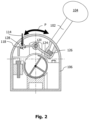
- Fig. 2 illustrates an engaged position of hand brake valve 100 in accordance with an embodiment of the present invention.
- hand brake valve 100 further includes a counterweight 126 which follows the (pivoting) movement (P) of handle 102, and wherein pivotable lever 118 is selectively pushed by counterweight 126 downwards at its second end 124 when handle 102 reaches the engaged position.
- counterweight 126 may move along with handle 102 or may stay in a stationary position with or without the help of a spring to retain counterweight 126 under tension, but as soon as handle 102 reaches the engaged position, counterweight 126 drops down.
- hand brake valve 100 further comprises an inclined slot 128 for selectively receiving counterweight 126 and for sliding counterweight 126 towards pivotable lever 118.
- a slot naturally conforms to the dimensional requirements of counterweight 126 as well as makes counterweight 126 move in a direction aligned to hit pivotable lever 118 at its second end 124.
- Inclined slot 128 not only provides the required direction for counterweight 126 to move down, but also facilitates ensuring that counterweight 126 pushes e.g., the right part of pivotable lever 118.
Landscapes
- Engineering & Computer Science (AREA)
- Transportation (AREA)
- Mechanical Engineering (AREA)
- Valves And Accessory Devices For Braking Systems (AREA)
- Indication Of The Valve Opening Or Closing Status (AREA)
Abstract
Description
- The present invention generally relates to the field of hand brake valves, which, for instance, are used in commercial vehicles for applying and releasing a parking brake.
- Conventional hand brake valves, in particular the ones that are used in applying and releasing the parking brake of the commercial vehicles are known. For instance, the European patent publication
EP3022097 is one such hand brake valve. - In some conventional hand brake valves, a feedback means is provided within the device to inform the drivers/users/operators of the commercial vehicles whether an intended movement in relation to a handle of the hand brake valves has been successful or not. One of the means for providing such a feedback to the drivers is an audible "click" noise. Another means for providing such a feedback or combined with the audible click to the drivers is through a tiny tactile force feedback experienced by the drivers after completing the intended movement of the handle of the hand brake valves.
- In certain operation conditions such feedback means discussed above may not be enough for the drivers of the commercial vehicles to know or realize that the hand brake valve has been engaged or not. This is particularly relevant in situations, wherein due to external factors or the environment in which the conventional hand brake valves operate and/or due to faulty working of the hand brake valves, the hand brake valves may wrongly indicate to the user or the drivers of the commercial vehicle with the requisite feedback as mentioned in the previous paragraph, but in fact, are not actually engaged i.e., the intended movement of the handle is not successful.
- It is one of the objectives of the present invention to provide further improvements in relation the feedback means of the hand brake valves, whereby the drivers or operators of the commercial vehicles can successfully identify whether the intended movement of the handle of the hand brake valves to engage or disengage the parking brake has been completed.
- In accordance with an embodiment of the present invention, a hand brake valve is disclosed. The hand brake valve comprises a housing, a handle that is configured to pivot with respect to a geometric center point, wherein the handle pivots from a non-engaged position towards an engaged position and/or vice-versa, and indicating means for indicating that the hand brake valve is in the engaged position, wherein the indicating means is configured to physically draw an indicator element outside the housing so as to provide a user of the hand brake valve with a visual signal that the hand brake valve is in the engaged position. One of the technical advantages of providing the indicating means according to the present invention, is that, by drawing the indicator element out of the housing, a simple mechanism is created which combines a visual indication to the user of the hand brake valve while at the same time, optionally, providing an audible click. Such a simple mechanism can be provided as a standalone confirmation to the driver of the vehicle or the user of the hand brake valve or can be combined with an electronic switch activating a lamp in a vehicle dashboard.
- The term "indicating means", in accordance with the present embodiment, may refer to a device or an apparatus or a group of components that facilitates indicating the engaged position of the hand brake valve.
- In accordance with the above embodiment or in relation to a different embodiment, when the handle is at the non-engaged position, the indicator element is completely within the housing. Such a clear separation of the position of the indicator element within or outside the housing enables the user of hand brake valve to discern what the actual position of the hand brake valve is, with clarity.
- Furthermore, in relation to one or more of the above-mentioned embodiments, the indicating means further includes a linear tube for receiving the indicator element such that the indicator element linearly reciprocates within the linear tube, wherein the linear tube is preferably integrally formed with respect to the housing. The linear tube, for instance, aligns the indicator element in a direction that is suitable for drawing the indicator element out of the housing without or with a least amount of resistance, which is caused e.g., due to friction between an internal surface of the linear tube and the indicator element.
- In one or more of the above embodiments, wherein the hand brake valve further comprises a pivotable lever, which is connected to the indicator element at a first end of the pivotable lever is configured to pivot with respect to a pivot shaft. The technical purpose of the pivotable lever is to maintain the position of the indicator element at the disengaged position (of the hand brake valve) within the housing and nudge the same indicator element outside the housing at the engaged position of the hand brake valve, particularly when the handle pivots to the appropriate position in the direction as indicated in the accompanying figures.
- In conjunction with the embodiment explained in the previous paragraph, wherein the hand brake valve further includes a counterweight which follows the movement of the handle, and wherein the pivotable lever is selectively pushed by the counterweight downwards at its second end when the handle reaches the engaged position. In this present context, the word "follows" may mean that the counterweight follows the motion or the moment of the handle. For instance, the arcuate motion of the handle is closely followed up to a point and then the counterweight drops at a slot to move the pin outside the housing. Furthermore, when the handle reaches the engaged position, the counterweight pushes the pivotable lever down at the second end such that the indicator element is drawn outside the housing. With the help of this counterweight pushing the pivotable lever, in addition to pushing the indicator element out of the housing, the user of the hand brake valve may additionally hear an audible signal such as a "click" noise to be assured of the function that the hand brake valve has indeed been moved to the engaged position. In a particular implementation, the counterweight is held under the tension exerted by a spring, and as soon as the handle of the hand brake valve reaches the engaged position, the tension of the spring may be released and the counterweight falls down to hit the second end of the pivotable lever.
- Still furthermore, the pivotable lever of the one or more embodiments of the present invention includes a slot for receiving the indicator element to establish a mechanical connection between the pivotable lever and the indicator element. It may however be necessary to provide a feature such that the indicator element is not released from the pivotable lever once it is moved or drawn outside the housing of the hand brake valve. This ensures that the pulling the indicator element within the housing and drawing it outside can be done repeatedly in cycles of operation of the hand brake valve.
- In relation to one or more of the above embodiments, the handle pivots with respect to the geometric center point (C) with the help of a pivoting element, wherein the pivoting element is received at an arcuate receiver.
- Furthermore, the hand brake valve, in accordance with the one or more embodiments discussed above, further comprises an inclined slot for selectively receiving the counterweight and for sliding the counterweight towards the pivotable lever. Such a slot naturally conforms to the dimensional requirements of the counterweight as well as makes the counterweight move in a direction aligned to hit the pivotable lever at its second end, e.g., at an appropriate location. Thus, the inclined slot not only provides the required direction for the counterweight to move down, but also facilitates ensuring that the counterweight pushes e.g., the right part of the pivotable lever. This ensures that the indicator element is drawn out of the housing with necessary reliability.
- On a different, the hand brake valve of the above embodiments may additionally include an electric switch actuated by the indicating means, wherein the electric switch activates directly or indirectly (e.g. via a vehicle electronic control unit) either a light signal or the auditory signal to confirm that the hand brake valve is (indeed) in the engaged position, and wherein, preferably, the light signal indicating that the hand brake valve is in the engaged position is provided at a vehicle dashboard.
-
-
Fig. 1 illustrates a non-engaged position of a hand brake valve in accordance with an embodiment of the present invention; and -
Fig. 2 illustrates an engaged position of a hand brake valve in accordance with an embodiment of the present invention. -
Fig. 1 illustrates a non-engaged position of ahand brake valve 100 in accordance with an embodiment of the present invention. - In the present embodiment,
hand brake valve 100 comprises ahousing 106, ahandle 102 that is configured to pivot with respect to a geometric center point (C), wherein handle 102 pivots from a non-engaged position towards an engaged position and/or vice-versa and indicatingmeans 112 for indicating that thehand brake valve 100 is in the engaged position. The term "indicating means", in accordance with the present embodiment, may refer to a device or an apparatus or a group of components that facilitates indicating the engaged position ofhand brake valve 100. For instance, as mentioned above, handle 102 while pivoting with respect to the geometric center point C, it can move along a pivoting movement as marked e.g., with the reference sign "P" inFig. 1 . This movement is facilitated by havinghandle 102 connected with apivoting element 108 which has acircular surface 109. Thiscircular surface 109 ofpivoting element 108 coordinates with anarcuate receiver 110 to facilitate the pivoting movement ofhandle 102. For the sake of completeness, it is noted that the physical connection betweenhandle 102 andpivoting element 108 is not directly shown inFig. 1 , but such a physical connection does exist. - Furthermore, in accordance with the present embodiment, indicating
means 112 is specifically configured to physically draw anindicator element 114 outsidehousing 106 so as to provide a user ofhand brake valve 100 with a visual signal thathand brake valve 100 is in the engaged position. In particular, according to the illustration of the present embodiment,indicator element 114 is pushed out ofhousing 106 as will be shown in the explanation below. One of the technical advantages of providingindicating means 112 according to the present invention, is that, by drawing indicator element 11 out ofhousing 106, a simple mechanism is created which combines a visual indication to the user ofhand brake valve 100 while at the same time, providing an audible click (more on this below). Such a simple mechanism can be provided as a standalone confirmation to the driver of the vehicle or the user ofhand brake valve 100 or can be combined with an electronic switch (not shown) activating a lamp (not shown) in a vehicle dashboard (not shown). - In accordance with the same or different embodiment, when
handle 102 is at the non-engaged position,indicator element 114 is completely withinhousing 106. Such a clear separation of the position ofindicator element 114 within oroutside housing 106 enables the user ofhand brake valve 100 to discern what the actual position ofhand brake valve 100 is, with clarity. As will be shown during the explanation of other features ofhand brake valve 100 of the present invention, the errors or inadvertent wrong signals regarding the position ofhandle 102 ofhand brake valve 100 is substantially reduced to the simplified mechanism. - As shown also in
fig. 1 , indicatingmeans 112 further includes alinear tube 116 forreceiving indicator element 114 such thatindicator element 114 linearly reciprocates withinlinear tube 116, whereinlinear tube 116 is preferably integrally formed with respect tohousing 106.Linear tube 116, for instance, alignsindicator element 114 in a direction that is suitable fordrawing indicator element 114 out ofhousing 106 without resistance. - Further, in an embodiment of the present invention,
hand brake valve 100 further comprises apivotable lever 118, which is connected toindicator element 114 at afirst end 122 ofpivotable lever 118 is configured to pivot with respect to apivot shaft 120. This region wherepivotable lever 118 andindicator element 114 are connected to each other is marked with reference sign "128" inFig. 1 . The technical purpose ofpivotable lever 118 is to maintain the position ofindicator element 114 at the disengaged position (of hand brake valve 100) withinhousing 106 and nudgesame indicator element 114 outsidehousing 106 at the engaged position, particularly when handle 102 pivots to the appropriate position in the direction as indicated with reference sign "P" infigs. 1 and2 . - It follows from the above, the
pivotable lever 118 includes a slot (not shown inFigs. 1 and2 ) for receivingindicator element 114 to establish a mechanical connection betweenpivotable lever 118 andindicator element 114. Further, handle 102 pivots with respect to the geometric center point (C) with the help of apivoting element 108, wherein pivotingelement 108 is received at anarcuate receiver 110. - In accordance with one or more above embodiments discussed in relation to
Fig. 1 ,hand brake valve 100 further comprises an electric switch (not shown in figures) actuated by indicatingmeans 112. In accordance with this implementation, the electric switch provides the possibility of indicating thathand brake valve 100 is in an engaged position with the help of e.g., a lamp. - Furthermore, the electric switch may also activate either a light signal or the auditory signal to confirm that
hand brake valve 100 is in the engaged position, and wherein, preferably, the light signal indicating thathand brake valve 100 is in the engaged position is provided at a vehicle dashboard (not shown in the figures). -
Fig. 2 illustrates an engaged position ofhand brake valve 100 in accordance with an embodiment of the present invention. - In the same or different embodiment as discussed in the previous paragraphs,
hand brake valve 100 further includes acounterweight 126 which follows the (pivoting) movement (P) ofhandle 102, and whereinpivotable lever 118 is selectively pushed bycounterweight 126 downwards at itssecond end 124 whenhandle 102 reaches the engaged position. In this way, when the user ofhand brake valve 100 moves handle 102 viaknob 104 from a disengaged position,counterweight 126 may move along withhandle 102 or may stay in a stationary position with or without the help of a spring to retaincounterweight 126 under tension, but as soon ashandle 102 reaches the engaged position,counterweight 126 drops down. - It follows from the above, wherein, when
handle 102 reaches the engaged position,counterweight 126 pushes (as it drops down)pivotable lever 118 down atsecond end 124 such thatindicator element 114 is drawn outside housing 106 (c.f.Fig. 2 ). With the help of thiscounterweight 126 pushingpivotable lever 118, in addition to pushingindicator element 114 out ofhousing 106, the user ofhand brake valve 100 may additionally hear an audible signal such as a "click" noise to be assured of the function thathand brake valve 100 has indeed been moved to the engaged position. - Finally, as can be taken also from
Fig. 2 ,hand brake valve 100 further comprises aninclined slot 128 for selectively receivingcounterweight 126 and for slidingcounterweight 126 towardspivotable lever 118. Such a slot naturally conforms to the dimensional requirements ofcounterweight 126 as well as makescounterweight 126 move in a direction aligned to hitpivotable lever 118 at itssecond end 124.Inclined slot 128 not only provides the required direction forcounterweight 126 to move down, but also facilitates ensuring thatcounterweight 126 pushes e.g., the right part ofpivotable lever 118. -
- 100 -
- hand brake valve
- 102 -
- handle
- 104 -
- handle knob
- 106 -
- housing
- 108 -
- pivoting element
- 109 -
- circular surface of pivoting
element 108 - 110 -
- arcuate receiver
- 112 -
- indicating means
- 114 -
- indicator element
- C -
- geometric center point
- P -
- pivoting movement
- 116 -
- linear tube
- 118 -
- pivotable lever
- 120 -
- pivot shaft
- 122 -
- first end of
pivotable lever 118 - 124 -
- second end of
pivotable lever 118 - 126 -
- counterweight
- 128 -
- region where
pivotable lever 118 andindicator element 114 are connected to each other
Claims (11)
- A hand brake valve (100), comprisinga housing (106),a handle (102) that is configured to pivot with respect to a geometric center point (C), wherein the handle (102) pivots from a non-engaged position towards an engaged position and/or vice-versa, andindicating means (112) for indicating that the hand brake valve (100) is in the engaged position,characterized in that,the indicating means (112) is configured to physically draw an indicator element (114) outside the housing (106) so as to provide a user of the hand brake valve (100) with a visual signal that the hand brake valve (100) is in the engaged position.
- The hand brake valve (100) according to claim 1, wherein, when the handle (102) is at the non-engaged position, the indicator element (114) is completely within the housing (106).
- The hand brake valve (100) according to claim 1 or claim 2, wherein the indicating means (112) further includes a linear tube (116) for receiving the indicator element (114) such that the indicator element (114) linearly reciprocates within the linear tube (116), wherein the linear tube (116) is preferably integrally formed with respect to the housing (106).
- The hand brake valve (100) according to any one of the above claims, wherein the hand brake valve (100) further comprises a pivotable lever (118), which is connected to the indicator element (114) at a first end (122) of the pivotable lever (118) is configured to pivot with respect to a pivot shaft (120).
- The hand brake valve (100) according to claim 4, wherein the hand brake valve (100) further includes a counterweight (126) which follows the movement of the handle (102), and wherein the pivotable lever (118) is selectively pushed by the counterweight (126) downwards at its second end (124) when the handle (102) reaches the engaged position.
- The hand brake valve (100) according to claim 5, wherein, when the handle (102) reaches the engaged position, the counterweight (126) pushes the pivotable lever (118) down at the second end (124) such that the indicator element (114) is drawn outside the housing (106).
- The hand brake valve (100) according to claim 4, wherein the pivotable lever (118) includes a slot for receiving the indicator element (114) to establish a mechanical connection between the pivotable lever (118) and the indicator element (114).
- The hand brake valve (100) according to any one of the above claims, wherein the handle (102) pivots with respect to the geometric center point (C) with the help of a pivoting element (108), wherein the pivoting element (108) is received at an arcuate receiver (110).
- The hand brake valve (100) according to claim 5, wherein the hand brake valve (100) further comprises an inclined slot (128) for selectively receiving the counterweight (126) and for sliding the counterweight (126) towards the pivotable lever (118).
- The hand brake valve (100) according to any one of the above claims, wherein the hand brake valve (100) further comprises an electric switch actuated by the indicating means (112).
- The hand brake valve (100) according to claim 10, wherein the electric switch activates either a light signal or the auditory signal to confirm that the hand brake valve (100) is in the engaged position, and wherein, preferably, the light signal indicating that the hand brake valve (100) is in the engaged position is provided at a vehicle dashboard.
Priority Applications (2)
| Application Number | Priority Date | Filing Date | Title |
|---|---|---|---|
| EP22183218.1A EP4303087B1 (en) | 2022-07-06 | 2022-07-06 | A hand brake valve with means for indicating an engaged position |
| CN202310769468.6A CN117360464A (en) | 2022-07-06 | 2023-06-27 | Hand brake valve with means for indicating engagement position |
Applications Claiming Priority (1)
| Application Number | Priority Date | Filing Date | Title |
|---|---|---|---|
| EP22183218.1A EP4303087B1 (en) | 2022-07-06 | 2022-07-06 | A hand brake valve with means for indicating an engaged position |
Publications (2)
| Publication Number | Publication Date |
|---|---|
| EP4303087A1 true EP4303087A1 (en) | 2024-01-10 |
| EP4303087B1 EP4303087B1 (en) | 2025-03-26 |
Family
ID=82399324
Family Applications (1)
| Application Number | Title | Priority Date | Filing Date |
|---|---|---|---|
| EP22183218.1A Active EP4303087B1 (en) | 2022-07-06 | 2022-07-06 | A hand brake valve with means for indicating an engaged position |
Country Status (2)
| Country | Link |
|---|---|
| EP (1) | EP4303087B1 (en) |
| CN (1) | CN117360464A (en) |
Citations (3)
| Publication number | Priority date | Publication date | Assignee | Title |
|---|---|---|---|---|
| US3042061A (en) * | 1956-11-08 | 1962-07-03 | Berg Airlectro Products Co | Automatic shuttle safety valve |
| EP3022097A1 (en) | 2013-07-15 | 2016-05-25 | WABCO GmbH | Hand brake valve for braking systems of pneumatically braked motor vehicles |
| US20200114895A1 (en) * | 2018-10-12 | 2020-04-16 | Graham-White Manufacturing Company | Trip cock valve for a brake system on a rail car |
-
2022
- 2022-07-06 EP EP22183218.1A patent/EP4303087B1/en active Active
-
2023
- 2023-06-27 CN CN202310769468.6A patent/CN117360464A/en active Pending
Patent Citations (3)
| Publication number | Priority date | Publication date | Assignee | Title |
|---|---|---|---|---|
| US3042061A (en) * | 1956-11-08 | 1962-07-03 | Berg Airlectro Products Co | Automatic shuttle safety valve |
| EP3022097A1 (en) | 2013-07-15 | 2016-05-25 | WABCO GmbH | Hand brake valve for braking systems of pneumatically braked motor vehicles |
| US20200114895A1 (en) * | 2018-10-12 | 2020-04-16 | Graham-White Manufacturing Company | Trip cock valve for a brake system on a rail car |
Also Published As
| Publication number | Publication date |
|---|---|
| EP4303087B1 (en) | 2025-03-26 |
| CN117360464A (en) | 2024-01-09 |
Similar Documents
| Publication | Publication Date | Title |
|---|---|---|
| EP2075490B1 (en) | Vehicle control system | |
| CA2167322C (en) | A device for preventing an accelerator of a vehicle from being erroneously operated | |
| EP3176033B1 (en) | Rotary-type switch | |
| EP0459417B1 (en) | Control device for automatic transmission | |
| EP2261535A1 (en) | Shifter for automatic transmission | |
| EP1752688A1 (en) | Shift-by-wire gearshift device | |
| EP4303087B1 (en) | A hand brake valve with means for indicating an engaged position | |
| US3982614A (en) | Clutch release bearing monitoring device | |
| EP0748958A2 (en) | Shift lock mechanism for shift lever device | |
| JPH11115525A (en) | Shift lever device | |
| CN109458453B (en) | Vehicle gear shifting device | |
| US7603926B2 (en) | Shift-by-wire shifting with P position | |
| CN111664244B (en) | Knob type gear shifting lever device | |
| EP1253351B1 (en) | Shift lever device with locking mechanism | |
| JPH09112532A (en) | Idling device for push-pull control cable | |
| US5015807A (en) | Shift lever apparatus for automotive vehicles | |
| JP6641153B2 (en) | Electronic transmission system for vehicles using smart keys | |
| EP1094252A2 (en) | Column shift device with key interlock mechanism | |
| JP4634941B2 (en) | Shift device | |
| EP1108921A2 (en) | Locking apparatus for change lever of vehicle | |
| JP3938823B2 (en) | Shift lever device | |
| CN111188898B (en) | Device for vehicle and method for operating the same | |
| US2077511A (en) | Switch actuating attachment for motor vehicle clutch pedals | |
| JP6094472B2 (en) | Vehicle shifter device | |
| JP2015123958A (en) | Shifter device for vehicle |
Legal Events
| Date | Code | Title | Description |
|---|---|---|---|
| PUAI | Public reference made under article 153(3) epc to a published international application that has entered the european phase |
Free format text: ORIGINAL CODE: 0009012 |
|
| STAA | Information on the status of an ep patent application or granted ep patent |
Free format text: STATUS: THE APPLICATION HAS BEEN PUBLISHED |
|
| AK | Designated contracting states |
Kind code of ref document: A1 Designated state(s): AL AT BE BG CH CY CZ DE DK EE ES FI FR GB GR HR HU IE IS IT LI LT LU LV MC MK MT NL NO PL PT RO RS SE SI SK SM TR |
|
| STAA | Information on the status of an ep patent application or granted ep patent |
Free format text: STATUS: REQUEST FOR EXAMINATION WAS MADE |
|
| 17P | Request for examination filed |
Effective date: 20240703 |
|
| RBV | Designated contracting states (corrected) |
Designated state(s): AL AT BE BG CH CY CZ DE DK EE ES FI FR GB GR HR HU IE IS IT LI LT LU LV MC MK MT NL NO PL PT RO RS SE SI SK SM TR |
|
| GRAP | Despatch of communication of intention to grant a patent |
Free format text: ORIGINAL CODE: EPIDOSNIGR1 |
|
| STAA | Information on the status of an ep patent application or granted ep patent |
Free format text: STATUS: GRANT OF PATENT IS INTENDED |
|
| RIC1 | Information provided on ipc code assigned before grant |
Ipc: B60T 15/04 20060101AFI20241106BHEP |
|
| INTG | Intention to grant announced |
Effective date: 20241118 |
|
| GRAS | Grant fee paid |
Free format text: ORIGINAL CODE: EPIDOSNIGR3 |
|
| GRAA | (expected) grant |
Free format text: ORIGINAL CODE: 0009210 |
|
| STAA | Information on the status of an ep patent application or granted ep patent |
Free format text: STATUS: THE PATENT HAS BEEN GRANTED |
|
| AK | Designated contracting states |
Kind code of ref document: B1 Designated state(s): AL AT BE BG CH CY CZ DE DK EE ES FI FR GB GR HR HU IE IS IT LI LT LU LV MC MK MT NL NO PL PT RO RS SE SI SK SM TR |
|
| REG | Reference to a national code |
Ref country code: GB Ref legal event code: FG4D |
|
| REG | Reference to a national code |
Ref country code: CH Ref legal event code: EP |
|
| REG | Reference to a national code |
Ref country code: DE Ref legal event code: R096 Ref document number: 602022012162 Country of ref document: DE |
|
| REG | Reference to a national code |
Ref country code: IE Ref legal event code: FG4D |
|
| PG25 | Lapsed in a contracting state [announced via postgrant information from national office to epo] |
Ref country code: RS Free format text: LAPSE BECAUSE OF FAILURE TO SUBMIT A TRANSLATION OF THE DESCRIPTION OR TO PAY THE FEE WITHIN THE PRESCRIBED TIME-LIMIT Effective date: 20250626 |
|
| PG25 | Lapsed in a contracting state [announced via postgrant information from national office to epo] |
Ref country code: FI Free format text: LAPSE BECAUSE OF FAILURE TO SUBMIT A TRANSLATION OF THE DESCRIPTION OR TO PAY THE FEE WITHIN THE PRESCRIBED TIME-LIMIT Effective date: 20250326 |
|
| REG | Reference to a national code |
Ref country code: LT Ref legal event code: MG9D |
|
| PG25 | Lapsed in a contracting state [announced via postgrant information from national office to epo] |
Ref country code: NO Free format text: LAPSE BECAUSE OF FAILURE TO SUBMIT A TRANSLATION OF THE DESCRIPTION OR TO PAY THE FEE WITHIN THE PRESCRIBED TIME-LIMIT Effective date: 20250626 |
|
| PG25 | Lapsed in a contracting state [announced via postgrant information from national office to epo] |
Ref country code: HR Free format text: LAPSE BECAUSE OF FAILURE TO SUBMIT A TRANSLATION OF THE DESCRIPTION OR TO PAY THE FEE WITHIN THE PRESCRIBED TIME-LIMIT Effective date: 20250326 |
|
| PG25 | Lapsed in a contracting state [announced via postgrant information from national office to epo] |
Ref country code: LV Free format text: LAPSE BECAUSE OF FAILURE TO SUBMIT A TRANSLATION OF THE DESCRIPTION OR TO PAY THE FEE WITHIN THE PRESCRIBED TIME-LIMIT Effective date: 20250326 |
|
| PG25 | Lapsed in a contracting state [announced via postgrant information from national office to epo] |
Ref country code: BG Free format text: LAPSE BECAUSE OF FAILURE TO SUBMIT A TRANSLATION OF THE DESCRIPTION OR TO PAY THE FEE WITHIN THE PRESCRIBED TIME-LIMIT Effective date: 20250326 Ref country code: GR Free format text: LAPSE BECAUSE OF FAILURE TO SUBMIT A TRANSLATION OF THE DESCRIPTION OR TO PAY THE FEE WITHIN THE PRESCRIBED TIME-LIMIT Effective date: 20250627 |
|
| REG | Reference to a national code |
Ref country code: NL Ref legal event code: MP Effective date: 20250326 |
|
| PG25 | Lapsed in a contracting state [announced via postgrant information from national office to epo] |
Ref country code: NL Free format text: LAPSE BECAUSE OF FAILURE TO SUBMIT A TRANSLATION OF THE DESCRIPTION OR TO PAY THE FEE WITHIN THE PRESCRIBED TIME-LIMIT Effective date: 20250326 |
|
| PG25 | Lapsed in a contracting state [announced via postgrant information from national office to epo] |
Ref country code: SE Free format text: LAPSE BECAUSE OF FAILURE TO SUBMIT A TRANSLATION OF THE DESCRIPTION OR TO PAY THE FEE WITHIN THE PRESCRIBED TIME-LIMIT Effective date: 20250326 |
|
| REG | Reference to a national code |
Ref country code: AT Ref legal event code: MK05 Ref document number: 1778783 Country of ref document: AT Kind code of ref document: T Effective date: 20250326 |
|
| PG25 | Lapsed in a contracting state [announced via postgrant information from national office to epo] |
Ref country code: SM Free format text: LAPSE BECAUSE OF FAILURE TO SUBMIT A TRANSLATION OF THE DESCRIPTION OR TO PAY THE FEE WITHIN THE PRESCRIBED TIME-LIMIT Effective date: 20250326 |
|
| PG25 | Lapsed in a contracting state [announced via postgrant information from national office to epo] |
Ref country code: ES Free format text: LAPSE BECAUSE OF FAILURE TO SUBMIT A TRANSLATION OF THE DESCRIPTION OR TO PAY THE FEE WITHIN THE PRESCRIBED TIME-LIMIT Effective date: 20250326 Ref country code: PT Free format text: LAPSE BECAUSE OF FAILURE TO SUBMIT A TRANSLATION OF THE DESCRIPTION OR TO PAY THE FEE WITHIN THE PRESCRIBED TIME-LIMIT Effective date: 20250728 |
|
| PGFP | Annual fee paid to national office [announced via postgrant information from national office to epo] |
Ref country code: DE Payment date: 20250604 Year of fee payment: 4 |
|
| PG25 | Lapsed in a contracting state [announced via postgrant information from national office to epo] |
Ref country code: IT Free format text: LAPSE BECAUSE OF FAILURE TO SUBMIT A TRANSLATION OF THE DESCRIPTION OR TO PAY THE FEE WITHIN THE PRESCRIBED TIME-LIMIT Effective date: 20250326 Ref country code: PL Free format text: LAPSE BECAUSE OF FAILURE TO SUBMIT A TRANSLATION OF THE DESCRIPTION OR TO PAY THE FEE WITHIN THE PRESCRIBED TIME-LIMIT Effective date: 20250326 |
|
| PG25 | Lapsed in a contracting state [announced via postgrant information from national office to epo] |
Ref country code: AT Free format text: LAPSE BECAUSE OF FAILURE TO SUBMIT A TRANSLATION OF THE DESCRIPTION OR TO PAY THE FEE WITHIN THE PRESCRIBED TIME-LIMIT Effective date: 20250326 |
|
| PG25 | Lapsed in a contracting state [announced via postgrant information from national office to epo] |
Ref country code: EE Free format text: LAPSE BECAUSE OF FAILURE TO SUBMIT A TRANSLATION OF THE DESCRIPTION OR TO PAY THE FEE WITHIN THE PRESCRIBED TIME-LIMIT Effective date: 20250326 |
|
| PG25 | Lapsed in a contracting state [announced via postgrant information from national office to epo] |
Ref country code: RO Free format text: LAPSE BECAUSE OF FAILURE TO SUBMIT A TRANSLATION OF THE DESCRIPTION OR TO PAY THE FEE WITHIN THE PRESCRIBED TIME-LIMIT Effective date: 20250326 |
|
| PG25 | Lapsed in a contracting state [announced via postgrant information from national office to epo] |
Ref country code: SK Free format text: LAPSE BECAUSE OF FAILURE TO SUBMIT A TRANSLATION OF THE DESCRIPTION OR TO PAY THE FEE WITHIN THE PRESCRIBED TIME-LIMIT Effective date: 20250326 |
|
| PG25 | Lapsed in a contracting state [announced via postgrant information from national office to epo] |
Ref country code: IS Free format text: LAPSE BECAUSE OF FAILURE TO SUBMIT A TRANSLATION OF THE DESCRIPTION OR TO PAY THE FEE WITHIN THE PRESCRIBED TIME-LIMIT Effective date: 20250726 |
|
| REG | Reference to a national code |
Ref country code: DE Ref legal event code: R097 Ref document number: 602022012162 Country of ref document: DE |
|
| PG25 | Lapsed in a contracting state [announced via postgrant information from national office to epo] |
Ref country code: DK Free format text: LAPSE BECAUSE OF FAILURE TO SUBMIT A TRANSLATION OF THE DESCRIPTION OR TO PAY THE FEE WITHIN THE PRESCRIBED TIME-LIMIT Effective date: 20250326 |
|
| PG25 | Lapsed in a contracting state [announced via postgrant information from national office to epo] |
Ref country code: CZ Free format text: LAPSE BECAUSE OF FAILURE TO SUBMIT A TRANSLATION OF THE DESCRIPTION OR TO PAY THE FEE WITHIN THE PRESCRIBED TIME-LIMIT Effective date: 20250326 |
|
| PLBE | No opposition filed within time limit |
Free format text: ORIGINAL CODE: 0009261 |
|
| STAA | Information on the status of an ep patent application or granted ep patent |
Free format text: STATUS: NO OPPOSITION FILED WITHIN TIME LIMIT |
|
| REG | Reference to a national code |
Ref country code: CH Ref legal event code: L10 Free format text: ST27 STATUS EVENT CODE: U-0-0-L10-L00 (AS PROVIDED BY THE NATIONAL OFFICE) Effective date: 20260211 |
|
| REG | Reference to a national code |
Ref country code: CH Ref legal event code: H13 Free format text: ST27 STATUS EVENT CODE: U-0-0-H10-H13 (AS PROVIDED BY THE NATIONAL OFFICE) Effective date: 20260224 |
|
| 26N | No opposition filed |
Effective date: 20260105 |
|
| PG25 | Lapsed in a contracting state [announced via postgrant information from national office to epo] |
Ref country code: LU Free format text: LAPSE BECAUSE OF NON-PAYMENT OF DUE FEES Effective date: 20250706 |
|
| REG | Reference to a national code |
Ref country code: BE Ref legal event code: MM Effective date: 20250731 |
|
| PG25 | Lapsed in a contracting state [announced via postgrant information from national office to epo] |
Ref country code: BE Free format text: LAPSE BECAUSE OF NON-PAYMENT OF DUE FEES Effective date: 20250731 |
|
| PG25 | Lapsed in a contracting state [announced via postgrant information from national office to epo] |
Ref country code: FR Free format text: LAPSE BECAUSE OF NON-PAYMENT OF DUE FEES Effective date: 20250731 |
|
| PG25 | Lapsed in a contracting state [announced via postgrant information from national office to epo] |
Ref country code: CH Free format text: LAPSE BECAUSE OF NON-PAYMENT OF DUE FEES Effective date: 20250731 |
|
| PG25 | Lapsed in a contracting state [announced via postgrant information from national office to epo] |
Ref country code: LT Free format text: LAPSE BECAUSE OF FAILURE TO SUBMIT A TRANSLATION OF THE DESCRIPTION OR TO PAY THE FEE WITHIN THE PRESCRIBED TIME-LIMIT Effective date: 20250326 |
|
| PG25 | Lapsed in a contracting state [announced via postgrant information from national office to epo] |
Ref country code: IE Free format text: LAPSE BECAUSE OF NON-PAYMENT OF DUE FEES Effective date: 20250706 |
|
| PG25 | Lapsed in a contracting state [announced via postgrant information from national office to epo] |
Ref country code: MC Free format text: LAPSE BECAUSE OF FAILURE TO SUBMIT A TRANSLATION OF THE DESCRIPTION OR TO PAY THE FEE WITHIN THE PRESCRIBED TIME-LIMIT Effective date: 20250326 |
|
| PG25 | Lapsed in a contracting state [announced via postgrant information from national office to epo] |
Ref country code: CY Free format text: LAPSE BECAUSE OF FAILURE TO SUBMIT A TRANSLATION OF THE DESCRIPTION OR TO PAY THE FEE WITHIN THE PRESCRIBED TIME-LIMIT Effective date: 20250326 |