EP4303068A2 - Multi-motor high-voltage dc charging compatible adapter device, system and control method, and automobile - Google Patents
Multi-motor high-voltage dc charging compatible adapter device, system and control method, and automobile Download PDFInfo
- Publication number
- EP4303068A2 EP4303068A2 EP23162198.8A EP23162198A EP4303068A2 EP 4303068 A2 EP4303068 A2 EP 4303068A2 EP 23162198 A EP23162198 A EP 23162198A EP 4303068 A2 EP4303068 A2 EP 4303068A2
- Authority
- EP
- European Patent Office
- Prior art keywords
- voltage
- charging
- battery
- controller
- relay
- Prior art date
- Legal status (The legal status is an assumption and is not a legal conclusion. Google has not performed a legal analysis and makes no representation as to the accuracy of the status listed.)
- Pending
Links
Images






Classifications
-
- B—PERFORMING OPERATIONS; TRANSPORTING
- B60—VEHICLES IN GENERAL
- B60L—PROPULSION OF ELECTRICALLY-PROPELLED VEHICLES; SUPPLYING ELECTRIC POWER FOR AUXILIARY EQUIPMENT OF ELECTRICALLY-PROPELLED VEHICLES; ELECTRODYNAMIC BRAKE SYSTEMS FOR VEHICLES IN GENERAL; MAGNETIC SUSPENSION OR LEVITATION FOR VEHICLES; MONITORING OPERATING VARIABLES OF ELECTRICALLY-PROPELLED VEHICLES; ELECTRIC SAFETY DEVICES FOR ELECTRICALLY-PROPELLED VEHICLES
- B60L53/00—Methods of charging batteries, specially adapted for electric vehicles; Charging stations or on-board charging equipment therefor; Exchange of energy storage elements in electric vehicles
- B60L53/60—Monitoring or controlling charging stations
- B60L53/66—Data transfer between charging stations and vehicles
-
- B—PERFORMING OPERATIONS; TRANSPORTING
- B60—VEHICLES IN GENERAL
- B60L—PROPULSION OF ELECTRICALLY-PROPELLED VEHICLES; SUPPLYING ELECTRIC POWER FOR AUXILIARY EQUIPMENT OF ELECTRICALLY-PROPELLED VEHICLES; ELECTRODYNAMIC BRAKE SYSTEMS FOR VEHICLES IN GENERAL; MAGNETIC SUSPENSION OR LEVITATION FOR VEHICLES; MONITORING OPERATING VARIABLES OF ELECTRICALLY-PROPELLED VEHICLES; ELECTRIC SAFETY DEVICES FOR ELECTRICALLY-PROPELLED VEHICLES
- B60L15/00—Methods, circuits, or devices for controlling the traction-motor speed of electrically-propelled vehicles
- B60L15/007—Physical arrangements or structures of drive train converters specially adapted for the propulsion motors of electric vehicles
-
- B—PERFORMING OPERATIONS; TRANSPORTING
- B60—VEHICLES IN GENERAL
- B60L—PROPULSION OF ELECTRICALLY-PROPELLED VEHICLES; SUPPLYING ELECTRIC POWER FOR AUXILIARY EQUIPMENT OF ELECTRICALLY-PROPELLED VEHICLES; ELECTRODYNAMIC BRAKE SYSTEMS FOR VEHICLES IN GENERAL; MAGNETIC SUSPENSION OR LEVITATION FOR VEHICLES; MONITORING OPERATING VARIABLES OF ELECTRICALLY-PROPELLED VEHICLES; ELECTRIC SAFETY DEVICES FOR ELECTRICALLY-PROPELLED VEHICLES
- B60L53/00—Methods of charging batteries, specially adapted for electric vehicles; Charging stations or on-board charging equipment therefor; Exchange of energy storage elements in electric vehicles
- B60L53/10—Methods of charging batteries, specially adapted for electric vehicles; Charging stations or on-board charging equipment therefor; Exchange of energy storage elements in electric vehicles characterised by the energy transfer between the charging station and the vehicle
- B60L53/11—DC charging controlled by the charging station, e.g. mode 4
-
- B—PERFORMING OPERATIONS; TRANSPORTING
- B60—VEHICLES IN GENERAL
- B60L—PROPULSION OF ELECTRICALLY-PROPELLED VEHICLES; SUPPLYING ELECTRIC POWER FOR AUXILIARY EQUIPMENT OF ELECTRICALLY-PROPELLED VEHICLES; ELECTRODYNAMIC BRAKE SYSTEMS FOR VEHICLES IN GENERAL; MAGNETIC SUSPENSION OR LEVITATION FOR VEHICLES; MONITORING OPERATING VARIABLES OF ELECTRICALLY-PROPELLED VEHICLES; ELECTRIC SAFETY DEVICES FOR ELECTRICALLY-PROPELLED VEHICLES
- B60L53/00—Methods of charging batteries, specially adapted for electric vehicles; Charging stations or on-board charging equipment therefor; Exchange of energy storage elements in electric vehicles
- B60L53/10—Methods of charging batteries, specially adapted for electric vehicles; Charging stations or on-board charging equipment therefor; Exchange of energy storage elements in electric vehicles characterised by the energy transfer between the charging station and the vehicle
- B60L53/14—Conductive energy transfer
- B60L53/16—Connectors, e.g. plugs or sockets, specially adapted for charging electric vehicles
-
- B—PERFORMING OPERATIONS; TRANSPORTING
- B60—VEHICLES IN GENERAL
- B60L—PROPULSION OF ELECTRICALLY-PROPELLED VEHICLES; SUPPLYING ELECTRIC POWER FOR AUXILIARY EQUIPMENT OF ELECTRICALLY-PROPELLED VEHICLES; ELECTRODYNAMIC BRAKE SYSTEMS FOR VEHICLES IN GENERAL; MAGNETIC SUSPENSION OR LEVITATION FOR VEHICLES; MONITORING OPERATING VARIABLES OF ELECTRICALLY-PROPELLED VEHICLES; ELECTRIC SAFETY DEVICES FOR ELECTRICALLY-PROPELLED VEHICLES
- B60L53/00—Methods of charging batteries, specially adapted for electric vehicles; Charging stations or on-board charging equipment therefor; Exchange of energy storage elements in electric vehicles
- B60L53/20—Methods of charging batteries, specially adapted for electric vehicles; Charging stations or on-board charging equipment therefor; Exchange of energy storage elements in electric vehicles characterised by converters located in the vehicle
- B60L53/22—Constructional details or arrangements of charging converters specially adapted for charging electric vehicles
-
- B—PERFORMING OPERATIONS; TRANSPORTING
- B60—VEHICLES IN GENERAL
- B60L—PROPULSION OF ELECTRICALLY-PROPELLED VEHICLES; SUPPLYING ELECTRIC POWER FOR AUXILIARY EQUIPMENT OF ELECTRICALLY-PROPELLED VEHICLES; ELECTRODYNAMIC BRAKE SYSTEMS FOR VEHICLES IN GENERAL; MAGNETIC SUSPENSION OR LEVITATION FOR VEHICLES; MONITORING OPERATING VARIABLES OF ELECTRICALLY-PROPELLED VEHICLES; ELECTRIC SAFETY DEVICES FOR ELECTRICALLY-PROPELLED VEHICLES
- B60L53/00—Methods of charging batteries, specially adapted for electric vehicles; Charging stations or on-board charging equipment therefor; Exchange of energy storage elements in electric vehicles
- B60L53/20—Methods of charging batteries, specially adapted for electric vehicles; Charging stations or on-board charging equipment therefor; Exchange of energy storage elements in electric vehicles characterised by converters located in the vehicle
- B60L53/24—Using the vehicle's propulsion converter for charging
-
- B—PERFORMING OPERATIONS; TRANSPORTING
- B60—VEHICLES IN GENERAL
- B60L—PROPULSION OF ELECTRICALLY-PROPELLED VEHICLES; SUPPLYING ELECTRIC POWER FOR AUXILIARY EQUIPMENT OF ELECTRICALLY-PROPELLED VEHICLES; ELECTRODYNAMIC BRAKE SYSTEMS FOR VEHICLES IN GENERAL; MAGNETIC SUSPENSION OR LEVITATION FOR VEHICLES; MONITORING OPERATING VARIABLES OF ELECTRICALLY-PROPELLED VEHICLES; ELECTRIC SAFETY DEVICES FOR ELECTRICALLY-PROPELLED VEHICLES
- B60L53/00—Methods of charging batteries, specially adapted for electric vehicles; Charging stations or on-board charging equipment therefor; Exchange of energy storage elements in electric vehicles
- B60L53/60—Monitoring or controlling charging stations
-
- B—PERFORMING OPERATIONS; TRANSPORTING
- B60—VEHICLES IN GENERAL
- B60L—PROPULSION OF ELECTRICALLY-PROPELLED VEHICLES; SUPPLYING ELECTRIC POWER FOR AUXILIARY EQUIPMENT OF ELECTRICALLY-PROPELLED VEHICLES; ELECTRODYNAMIC BRAKE SYSTEMS FOR VEHICLES IN GENERAL; MAGNETIC SUSPENSION OR LEVITATION FOR VEHICLES; MONITORING OPERATING VARIABLES OF ELECTRICALLY-PROPELLED VEHICLES; ELECTRIC SAFETY DEVICES FOR ELECTRICALLY-PROPELLED VEHICLES
- B60L53/00—Methods of charging batteries, specially adapted for electric vehicles; Charging stations or on-board charging equipment therefor; Exchange of energy storage elements in electric vehicles
- B60L53/60—Monitoring or controlling charging stations
- B60L53/62—Monitoring or controlling charging stations in response to charging parameters, e.g. current, voltage or electrical charge
-
- H—ELECTRICITY
- H02—GENERATION; CONVERSION OR DISTRIBUTION OF ELECTRIC POWER
- H02J—ELECTRIC POWER NETWORKS; CIRCUIT ARRANGEMENTS OR SYSTEMS FOR SUPPLYING OR DISTRIBUTING ELECTRIC POWER; SYSTEMS FOR STORING ELECTRIC ENERGY
- H02J7/00—Circuit arrangements for charging or discharging batteries or for supplying loads from batteries
- H02J7/40—Circuit arrangements for charging or discharging batteries or for supplying loads from batteries characterised by the exchange of charge or discharge related data
-
- H—ELECTRICITY
- H02—GENERATION; CONVERSION OR DISTRIBUTION OF ELECTRIC POWER
- H02J—ELECTRIC POWER NETWORKS; CIRCUIT ARRANGEMENTS OR SYSTEMS FOR SUPPLYING OR DISTRIBUTING ELECTRIC POWER; SYSTEMS FOR STORING ELECTRIC ENERGY
- H02J7/00—Circuit arrangements for charging or discharging batteries or for supplying loads from batteries
- H02J7/80—Circuit arrangements for charging or discharging batteries or for supplying loads from batteries including monitoring or indicating arrangements
-
- H—ELECTRICITY
- H02—GENERATION; CONVERSION OR DISTRIBUTION OF ELECTRIC POWER
- H02J—ELECTRIC POWER NETWORKS; CIRCUIT ARRANGEMENTS OR SYSTEMS FOR SUPPLYING OR DISTRIBUTING ELECTRIC POWER; SYSTEMS FOR STORING ELECTRIC ENERGY
- H02J7/00—Circuit arrangements for charging or discharging batteries or for supplying loads from batteries
- H02J7/90—Regulation of charging or discharging current or voltage
- H02J7/933—Regulation of charging or discharging current or voltage the cycle being controlled or terminated in response to electric parameters
-
- B—PERFORMING OPERATIONS; TRANSPORTING
- B60—VEHICLES IN GENERAL
- B60L—PROPULSION OF ELECTRICALLY-PROPELLED VEHICLES; SUPPLYING ELECTRIC POWER FOR AUXILIARY EQUIPMENT OF ELECTRICALLY-PROPELLED VEHICLES; ELECTRODYNAMIC BRAKE SYSTEMS FOR VEHICLES IN GENERAL; MAGNETIC SUSPENSION OR LEVITATION FOR VEHICLES; MONITORING OPERATING VARIABLES OF ELECTRICALLY-PROPELLED VEHICLES; ELECTRIC SAFETY DEVICES FOR ELECTRICALLY-PROPELLED VEHICLES
- B60L2210/00—Converter types
- B60L2210/40—DC to AC converters
-
- B—PERFORMING OPERATIONS; TRANSPORTING
- B60—VEHICLES IN GENERAL
- B60L—PROPULSION OF ELECTRICALLY-PROPELLED VEHICLES; SUPPLYING ELECTRIC POWER FOR AUXILIARY EQUIPMENT OF ELECTRICALLY-PROPELLED VEHICLES; ELECTRODYNAMIC BRAKE SYSTEMS FOR VEHICLES IN GENERAL; MAGNETIC SUSPENSION OR LEVITATION FOR VEHICLES; MONITORING OPERATING VARIABLES OF ELECTRICALLY-PROPELLED VEHICLES; ELECTRIC SAFETY DEVICES FOR ELECTRICALLY-PROPELLED VEHICLES
- B60L2220/00—Electrical machine types; Structures or applications thereof
- B60L2220/40—Electrical machine applications
- B60L2220/42—Electrical machine applications with use of more than one motor
-
- H—ELECTRICITY
- H02—GENERATION; CONVERSION OR DISTRIBUTION OF ELECTRIC POWER
- H02J—ELECTRIC POWER NETWORKS; CIRCUIT ARRANGEMENTS OR SYSTEMS FOR SUPPLYING OR DISTRIBUTING ELECTRIC POWER; SYSTEMS FOR STORING ELECTRIC ENERGY
- H02J2105/00—Networks for supplying or distributing electric power characterised by their spatial reach or by the load
- H02J2105/30—Networks for supplying or distributing electric power characterised by their spatial reach or by the load the load networks being external to vehicles, i.e. exchanging power with vehicles
- H02J2105/33—Networks for supplying or distributing electric power characterised by their spatial reach or by the load the load networks being external to vehicles, i.e. exchanging power with vehicles exchanging power with road vehicles
- H02J2105/37—Networks for supplying or distributing electric power characterised by their spatial reach or by the load the load networks being external to vehicles, i.e. exchanging power with vehicles exchanging power with road vehicles exchanging power with electric vehicles [EV] or with hybrid electric vehicles [HEV]
-
- H—ELECTRICITY
- H02—GENERATION; CONVERSION OR DISTRIBUTION OF ELECTRIC POWER
- H02J—ELECTRIC POWER NETWORKS; CIRCUIT ARRANGEMENTS OR SYSTEMS FOR SUPPLYING OR DISTRIBUTING ELECTRIC POWER; SYSTEMS FOR STORING ELECTRIC ENERGY
- H02J2207/00—Details of circuit arrangements for charging or discharging batteries or supplying loads from batteries
- H02J2207/20—Charging or discharging characterised by the power electronics converter
-
- H—ELECTRICITY
- H02—GENERATION; CONVERSION OR DISTRIBUTION OF ELECTRIC POWER
- H02J—ELECTRIC POWER NETWORKS; CIRCUIT ARRANGEMENTS OR SYSTEMS FOR SUPPLYING OR DISTRIBUTING ELECTRIC POWER; SYSTEMS FOR STORING ELECTRIC ENERGY
- H02J2207/00—Details of circuit arrangements for charging or discharging batteries or supplying loads from batteries
- H02J2207/40—Details of circuit arrangements for charging or discharging batteries or supplying loads from batteries adapted for charging from various sources, e.g. AC, DC or multivoltage
-
- H—ELECTRICITY
- H02—GENERATION; CONVERSION OR DISTRIBUTION OF ELECTRIC POWER
- H02J—ELECTRIC POWER NETWORKS; CIRCUIT ARRANGEMENTS OR SYSTEMS FOR SUPPLYING OR DISTRIBUTING ELECTRIC POWER; SYSTEMS FOR STORING ELECTRIC ENERGY
- H02J7/00—Circuit arrangements for charging or discharging batteries or for supplying loads from batteries
- H02J7/60—Circuit arrangements for charging or discharging batteries or for supplying loads from batteries including safety or protection arrangements
- H02J7/663—Circuit arrangements for charging or discharging batteries or for supplying loads from batteries including safety or protection arrangements using battery or load disconnect circuits
-
- Y—GENERAL TAGGING OF NEW TECHNOLOGICAL DEVELOPMENTS; GENERAL TAGGING OF CROSS-SECTIONAL TECHNOLOGIES SPANNING OVER SEVERAL SECTIONS OF THE IPC; TECHNICAL SUBJECTS COVERED BY FORMER USPC CROSS-REFERENCE ART COLLECTIONS [XRACs] AND DIGESTS
- Y02—TECHNOLOGIES OR APPLICATIONS FOR MITIGATION OR ADAPTATION AGAINST CLIMATE CHANGE
- Y02T—CLIMATE CHANGE MITIGATION TECHNOLOGIES RELATED TO TRANSPORTATION
- Y02T10/00—Road transport of goods or passengers
- Y02T10/60—Other road transportation technologies with climate change mitigation effect
- Y02T10/70—Energy storage systems for electromobility, e.g. batteries
-
- Y—GENERAL TAGGING OF NEW TECHNOLOGICAL DEVELOPMENTS; GENERAL TAGGING OF CROSS-SECTIONAL TECHNOLOGIES SPANNING OVER SEVERAL SECTIONS OF THE IPC; TECHNICAL SUBJECTS COVERED BY FORMER USPC CROSS-REFERENCE ART COLLECTIONS [XRACs] AND DIGESTS
- Y02—TECHNOLOGIES OR APPLICATIONS FOR MITIGATION OR ADAPTATION AGAINST CLIMATE CHANGE
- Y02T—CLIMATE CHANGE MITIGATION TECHNOLOGIES RELATED TO TRANSPORTATION
- Y02T90/00—Enabling technologies or technologies with a potential or indirect contribution to GHG emissions mitigation
- Y02T90/10—Technologies relating to charging of electric vehicles
- Y02T90/16—Information or communication technologies improving the operation of electric vehicles
Definitions
- the disclosure relates to the technical field of high-voltage DC charging for new energy multi-motor electric vehicles, in particular to a multi-motor high-voltage DC charging compatible adapter device, system and control method, and an automobile.
- the disclosure provides a multi-motor high-voltage DC charging compatible adapter device, system and control method, and an automobile, which can form a system that has compatible adaptation functions for high-voltage DC charging piles with different voltage levels and can achieve greater charging power.
- the disclosure provides a multi-motor high-voltage DC charging compatible adapter device, including a high-voltage relay K1, a high-voltage relay K2, a high-voltage relay K3, a high-voltage relay K4, a resistor R3, capacitor C3, a high-voltage DC charging compatible adapter device controller, a high-voltage port and a low-voltage port;
- the disclosure provides a multi-motor high-voltage DC charging compatible adapter device, including a high-voltage relay K1, a high-voltage relay K2, a high-voltage relay K3, a high-voltage relay K4, a resistor R3, capacitor C3, a high-voltage DC charging compatible adapter device controller, a high-voltage port, a low-voltage port and an inductor L1;
- the disclosure provides a multi-motor high-voltage DC charging compatible adapter device, including a high-voltage relay K1, a high-voltage relay K2, a high-voltage relay K3, a high-voltage relay K4, a resistor R3, capacitor C3, a high-voltage DC charging compatible adapter device controller, a high-voltage port, a low-voltage port, an inductor L1 and an inductor L2;
- the disclosure provides a multi-motor high-voltage DC charging compatible adapter device, including a high-voltage relay K1, a high-voltage relay K2, a high-voltage relay K3, a high-voltage relay K4, a resistor R3, capacitor C3, a high-voltage DC charging compatible adapter device controller, a high-voltage port, a low-voltage port and an inductor L2;
- the disclosure provides a first electric drive and a first controller, a second electric drive and a second controller, a battery and a battery controller, a vehicle controller and the multi-motor high-voltage DC charging compatible adapter device of the disclosure;
- the disclosure provides a control method of a multi-motor high-voltage DC charging compatible adapter system, using the multi-motor high-voltage DC charging compatible adapter system of the disclosure, after the multi-motor high-voltage DC charging compatible adapter system connected with a high-voltage DC charging pile, the control method includes following operations:
- the disclosure provides an automobile, including the multi-motor high-voltage DC charging compatible adapter system of the disclosure.
- the disclosure has following advantages: adding the multi-motor high-voltage DC charging compatible adapter device to the new energy multi-motor electric vehicle power system can form a system that has compatible adaptation functions for high-voltage DC charging piles with different voltage levels and can achieve greater charging power.
- the corresponding control method provided by the disclosure can realize a compatible adaptation of new energy electric vehicles to high-voltage DC charging piles with different voltage levels and have a higher power charging.
- a multi-motor high-voltage DC charging compatible adapter device includes a high-voltage relay K1, a high-voltage relay K2, a high-voltage relay K3, a high-voltage relay K4, a resistor R3, capacitor C3, a high-voltage DC charging compatible adapter device controller, a high-voltage port and a low-voltage port, and a connection relationship is as follows:
- a multi-motor high-voltage DC charging compatible adapter device includes a high-voltage relay K1, a high-voltage relay K2, a high-voltage relay K3, a high-voltage relay K4, a resistor R3, capacitor C3, a high-voltage DC charging compatible adapter device controller, a high-voltage port, a low-voltage port and an inductor L1, and a specific connection relationship is as follows:
- a multi-motor high-voltage DC charging compatible adapter device includes a high-voltage relay K1, a high-voltage relay K2, a high-voltage relay K3, a high-voltage relay K4, a resistor R3, capacitor C3, a high-voltage DC charging compatible adapter device controller, a high-voltage port, a low-voltage port, an inductor L1 and an inductor L2, and a specific connection relationship is as follows:
- a multi-motor high-voltage DC charging compatible adapter device includes a high-voltage relay K1, a high-voltage relay K2, a high-voltage relay K3, a high-voltage relay K4, a resistor R3, capacitor C3, a high-voltage DC charging compatible adapter device controller, a high-voltage port, a low-voltage port and an inductor L2, and a specific connection relationship is as follows:
- a multi-motor high-voltage DC charging compatible adapter system includes a first electric drive 10 and a first controller 11, a second electric drive 20 and a second controller 21, a battery and a battery controller, a vehicle controller and the multi-motor high-voltage DC charging compatible adapter device of the embodiment, and a specific connection relationship is as follows:
- FIG. 10 is a circuit topology example 1 of the multi-motor high-voltage DC charging compatible adapter system in this embodiment.
- the topology example uses the multi-motor high-voltage DC charging compatible adapter device as shown in FIG. 2 .
- the first electric drive 10 and the electric drive 20 respectively adopt a system equivalent circuit topology of an electronically controlled three-phase bridge arm and a parallel operation mode of the corresponding three-phase winding of the motor.
- a detailed control logic of this topology example is executed according to the control method and operations of the multi-motor high-voltage DC charging compatible adapter device system shown in FIG. 10 .
- a buck mode the high-voltage relay K1 and high-voltage relay K3 are connected, high-voltage relay K2 and high-voltage relay K4 are disconnected, a main positive relay of the battery and a main negative relay of the battery are connected, a power switch transistor S11 through a power switch transistor S13 are disconnected, a power switch transistor S21 through a power switch through S26 are disconnected, a power switch transistor S14 through a power switch transistor S16 run in the buck mode to realize an buck operation of the battery through the electric drive to the capacitor of the charging port.
- a boost mode the high voltage relay K1 and the high voltage relay K4 are connected (switched on), the high voltage relay K2 is disconnected(switched off), the main positive relay and the main negative relay of the battery are connected, the power switch transistor S14 through the power switch transistor S16 are disconnected, the power switch transistor S24 through the power switch transistor S26 are disconnected, the power switch transistor S11 through power switch transistor S13 and the power switch transistor S21 through power switch transistor S23 run in the boost mode, so as to realize a boost operation from the charging port to the battery through the electric drive.
- a direct charging mode the high voltage relay K2 is connected, the high voltage relay K1, the high voltage relay K3, and the high voltage relay K4 are disconnected, the main positive relay and the main negative relay of the battery are connected, the power switch transistor S11 through the power switch transistor S16 are disconnected, the power switch transistor S21 through the power switch transistor S26 are disconnected to operate in the direct charging mode, so as to realize a direct charging operation from the charging port to the battery.
- FIG. 11 is a circuit topology example 2 of the multi-motor high-voltage DC charging compatible adapter system in this embodiment.
- the topology example uses the multi-motor high-voltage DC charging compatible adapter device as shown in FIG. 3 .
- the first electric drive 10 and the second electric drive 20 respectively adopt the system equivalent circuit topology of the electronically controlled three-phase bridge arm and the parallel operation mode of the corresponding three-phase winding of the motor.
- a detailed control logic of this topology example is executed according to the control method and operations of the multi-motor high-voltage DC charging compatible adapter device system shown in FIG. 12 .
- the buck mode the high-voltage relay K1 and high-voltage relay K3 are connected, high-voltage relay K2 and high-voltage relay K4 are disconnected, the main positive relay of the battery and the main negative relay of the battery are connected, the power switch transistor S11 through the power switch transistor S13, the power switch transistor S21 through the power switch through S26 are disconnected, the power switch transistor S14 through the power switch transistor S16 run in the buck mode to realize the operation of the battery through the electric drive to the capacitor of the charging port.
- the boost mode the high voltage relay K1 and the high voltage relay K4 are connected, the high voltage relay K2 is disconnected, the main positive relay and the main negative relay of the battery are connected, the power switch transistor S14 through the power switch transistor S16, the power switch transistor S24 through the power switch transistor S26 are disconnected, the power switch transistor S11 through power switch transistor S13 and the power switch transistor S21 through power switch transistor S23 run in the boost mode, so as to realize the boost operation from the charging port to the battery through the electric drive.
- the direct charging mode the high voltage relay K2 is connected, the high voltage relay K1, the high voltage relay K3, and the high voltage relay K4 are disconnected, the main positive relay and the main negative relay of the battery are connected, the power switch transistor S11 through the power switch transistor S16, the power switch transistor S21 through the power switch transistor S26 are disconnected to operate in the direct charging mode, so as to realize the direct charging operation from the charging port to the battery.
- FIG. 12 is a circuit topology example 3 of the multi-motor high-voltage DC charging compatible adapter system in this embodiment.
- the topology example uses the multi-motor high-voltage DC charging compatible adapter device as shown in FIG. 4 .
- the first electric drive 10 and the second electric drive 20 respectively adopt the system equivalent circuit topology of the electronically controlled three-phase bridge arm and the parallel operation mode of the corresponding three-phase winding of the motor.
- a detailed control logic of this topology example is executed according to the control method and operations of the multi-motor high-voltage DC charging compatible adapter device system shown in FIG. 5 .
- the buck mode the high-voltage relay K1 and high-voltage relay K3 are connected, high-voltage relay K2 and high-voltage relay K4 are disconnected, the main positive relay of the battery and the main negative relay of the battery are connected, the power switch transistor S11 through the power switch transistor S13, the power switch transistor S21 through the power switch through S26 are disconnected, the power switch transistor S14 through the power switch transistor S16 run in the buck mode to realize the operation of the battery through the electric drive to the capacitor of the charging port.
- the boost mode the high voltage relay K1 and the high voltage relay K4 are connected, the high voltage relay K2 is disconnected, the main positive relay and the main negative relay of the battery are connected, the power switch transistor S14 through the power switch transistor S16, the power switch transistor S24 through the power switch transistor S26 are disconnected, the power switch transistor S11 through power switch transistor S13 and the power switch transistor S21 through power switch transistor S23 run in the boost mode, so as to realize the boost operation from the charging port to the battery through the electric drive.
- the direct charging mode the high voltage relay K2 is connected, the high voltage relay K1, the high voltage relay K3, and the high voltage relay K4 are disconnected, the main positive relay and the main negative relay of the battery are connected, the power switch transistor S11 through the power switch transistor S16, the power switch transistor S21 through the power switch transistor S26 are disconnected to operate in the direct charging mode, so as to realize the direct charging operation from the charging port to the battery.
- FIG. 13 is a circuit topology example 3 of the multi-motor high-voltage DC charging compatible adapter system in this embodiment.
- the topology example uses the multi-motor high-voltage DC charging compatible adapter device as shown in FIG. 4 .
- the topology example uses the multi-motor high-voltage DC charging compatible adapter device as shown in FIG. 4 .
- the first electric drive 10 and the second electric drive 20 respectively adopt the system equivalent circuit topology of the electronically controlled three-phase bridge arm and the parallel operation mode of the corresponding three-phase winding of the motor.
- a detailed control logic of this topology example is executed according to the control method and operations of the multi-motor high-voltage DC charging compatible adapter device system shown in FIG. 5 .
- the buck mode the high-voltage relay K1 and high-voltage relay K3 are connected, high-voltage relay K2 and high-voltage relay K4 are disconnected, the main positive relay of the battery and the main negative relay of the battery are connected, the power switch transistor S11 through the power switch transistor S13, the power switch transistor S21 through the power switch through S26 are disconnected, the power switch transistor S14 through the power switch transistor S16 run in the buck mode to realize the operation of the battery through the electric drive to the capacitor of the charging port.
- the boost mode the high voltage relay K1 and the high voltage relay K4 are connected, the high voltage relay K2 is disconnected, the main positive relay and the main negative relay of the battery are connected, the power switch transistor S14 through the power switch transistor S16, the power switch transistor S24 through the power switch transistor S26 are disconnected, the power switch transistor S11 through power switch transistor S13 and the power switch transistor S21 through power switch transistor S23 run in the boost mode, so as to realize the boost operation from the charging port to the battery through the electric drive.
- the direct charging mode the high voltage relay K2 is connected, the high voltage relay K1, the high voltage relay K3, and the high voltage relay K4 are disconnected, the main positive relay and the main negative relay of the battery are connected, the power switch transistor S11 through the power switch transistor S16, the power switch transistor S21 through the power switch transistor S26 are disconnected to operate in the direct charging mode, so as to realize the direct charging operation from the charging port to the battery.
- a control method of a multi-motor high-voltage DC charging compatible adapter system uses the multi-motor high-voltage DC charging compatible adapter system of the embodiment, after the multi-motor high-voltage DC charging compatible adapter system connected with a high-voltage DC charging pile, the control method includes following operations:
Landscapes
- Engineering & Computer Science (AREA)
- Power Engineering (AREA)
- Transportation (AREA)
- Mechanical Engineering (AREA)
- Electric Propulsion And Braking For Vehicles (AREA)
- Charge And Discharge Circuits For Batteries Or The Like (AREA)
- Dc-Dc Converters (AREA)
Abstract
Description
- The disclosure relates to the technical field of high-voltage DC charging for new energy multi-motor electric vehicles, in particular to a multi-motor high-voltage DC charging compatible adapter device, system and control method, and an automobile.
- Users of new energy electric vehicles have higher and higher requirements for battery life, and battery pack solutions using multi-battery cell modules in parallel to form larger power capacity and higher voltage levels are also increasingly used in new energy electric vehicles. At present, there are many types of charging piles on the market, mainly divided into two types: 800V and 500V. If the battery voltage level of the electric vehicle is higher than the voltage level of the charging pile, there will be situations where the battery cannot be charged or not fully charged, which will affect the user's experience of new energy electric vehicles and hinder the further popularization of new energy electric vehicles.
- For new energy multi-motor electric vehicles, a realization of a model that is compatible with different voltage levels of high-voltage DC charging piles, full use of the conventional multi-motor hardware advantages to achieve greater charging power and users' fast charging needs is crucial to improving the user's experience of new energy electric vehicles. Considering the needs of users for fast charging and the manufacturing cost of new energy electric vehicles, based on the conventional power system hardware of multi-motor electric vehicles, compatibility and adaptation of high-voltage DC charging and higher charging power through adding specific module devices are the focus of competition in the industry.
- Therefore, it is necessary to develop a new multi-motor high-voltage DC charging compatible adapter device, system, control method, and automobile.
- The disclosure provides a multi-motor high-voltage DC charging compatible adapter device, system and control method, and an automobile, which can form a system that has compatible adaptation functions for high-voltage DC charging piles with different voltage levels and can achieve greater charging power.
- In one hand, the disclosure provides a multi-motor high-voltage DC charging compatible adapter device, including a high-voltage relay K1, a high-voltage relay K2, a high-voltage relay K3, a high-voltage relay K4, a resistor R3, capacitor C3, a high-voltage DC charging compatible adapter device controller, a high-voltage port and a low-voltage port;
- the low-voltage port is connected with the high-voltage DC charging compatible adapter device controller, the low-voltage port comprises a low-voltage power supply port and a low-voltage communication port,
- the high-voltage port comprises a positive terminal in+ of a high-voltage DC input terminal, a negative terminal in- of a high-voltage DC input terminal, a positive terminal out+ of a high-voltage DC output terminal, a negative terminal out-A1 of a high-voltage DC output terminal, a negative terminal out-A2 of the high-voltage DC output terminal and a negative terminal out-B of the high-voltage DC output terminal, the positive terminal in+ of the high-voltage DC input terminal and the positive terminal out+ of the high-voltage DC output terminal are respectively connected with one end of the high-voltage relay K3, the other end of the high-voltage relay K3 is connected with the negative terminal out-A1 of the high-voltage DC output terminal through the resistor R3, the capacitor C3 and resistor R3 are connected in parallel, a connection point between the negative terminal out-A1 of the high-voltage DC output terminal and the resistor R3 is connected with the negative terminal out-A2 of the high-voltage DC output terminal through the high-voltage relay K4, the connection point between the negative terminal out-A1 of the high-voltage DC output terminal and the resistor R3 is further connected with the negative terminal out-B of the high-voltage DC output terminal through the high-voltage relay K1 and the high-voltage relay K2 successively, a connection point of the high-voltage relay K1 and the high-voltage relay K2 is connected with the negative terminal in- of the high-voltage DC input terminal,
- the high-voltage DC charging compatible adapter device controller is configured to be with communication functions, high-voltage relay K2 driving and control functions, high-voltage relay K1 driving and control functions, high-voltage relay K3 driving and control functions, high-voltage relay K4 driving and control functions, a capacitor C3 voltage detection function and a communication function, and a function of detecting a capacitor voltage UC3 and sending it out in real time through the low-voltage communication port, and the high-voltage DC charging compatible adapter device controller is respectively connected with control terminals of the high-voltage relay K1, the high-voltage relay K2, the high-voltage relay K3, and the high-voltage relay K4.
- On a second hand, the disclosure provides a multi-motor high-voltage DC charging compatible adapter device, including a high-voltage relay K1, a high-voltage relay K2, a high-voltage relay K3, a high-voltage relay K4, a resistor R3, capacitor C3, a high-voltage DC charging compatible adapter device controller, a high-voltage port, a low-voltage port and an inductor L1;
- the low-voltage port is connected with the high-voltage DC charging compatible adapter device controller, the low-voltage port comprises a low-voltage power supply port and a low-voltage communication port,
- the high-voltage port comprises a positive terminal in+ of a high-voltage DC input terminal, a negative terminal in- of a high-voltage DC input terminal, a positive terminal out+ of a high-voltage DC output terminal, a negative terminal out-A1 of a high-voltage DC output terminal, a negative terminal out-A2 of the high-voltage DC output terminal and a negative terminal out-B of the high-voltage DC output terminal, the positive terminal in+ of the high-voltage DC input terminal and the positive terminal out+ of the high-voltage DC output terminal are respectively connected with one end of the high-voltage relay K3, the other end of the high-voltage relay K3 and the inductor L1 is connected with the negative terminal out-A1 of the high-voltage DC output terminal through the resistor R3, the capacitor C3 and resistor R3 are connected in parallel, a connection point between the inductor L1 and the resistor R3 is connected with the negative terminal out-A2 of the high-voltage DC output terminal through the high-voltage relay K4, the connection point between the inductor L1 and the resistor R3 is further connected with the negative terminal out-B of the high-voltage DC output terminal through the high-voltage relay K1 and the high-voltage relay K2 successively, a connection point of the high-voltage relay K1 and the high-voltage relay K2 is connected with the negative terminal in- of the high-voltage DC input terminal,
- the high-voltage DC charging compatible adapter device controller is configured to be with communication functions, high-voltage relay K2 driving and control functions, high-voltage relay K1 driving and control functions, high-voltage relay K3 driving and control functions, high-voltage relay K4 driving and control functions, a capacitor C3 voltage detection function and a communication function, and a function of detecting a capacitor voltage UC3 and sending it out in real time through the low-voltage communication port, and the high-voltage DC charging compatible adapter device controller is respectively connected with control terminals of the high-voltage relay K1, the high-voltage relay K2, the high-voltage relay K3, and the high-voltage relay K4.
- On a third hand, the disclosure provides a multi-motor high-voltage DC charging compatible adapter device, including a high-voltage relay K1, a high-voltage relay K2, a high-voltage relay K3, a high-voltage relay K4, a resistor R3, capacitor C3, a high-voltage DC charging compatible adapter device controller, a high-voltage port, a low-voltage port, an inductor L1 and an inductor L2;
- the low-voltage port is connected with the high-voltage DC charging compatible adapter device controller, the low-voltage port comprises a low-voltage power supply port and a low-voltage communication port,
- the high-voltage port comprises a positive terminal in+ of a high-voltage DC input terminal, a negative terminal in- of a high-voltage DC input terminal, a positive terminal out+ of a high-voltage DC output terminal, a negative terminal out-A1 of a high-voltage DC output terminal, a negative terminal out-A2 of the high-voltage DC output terminal and a negative terminal out-B of the high-voltage DC output terminal, the positive terminal in+ of the high-voltage DC input terminal and the positive terminal out+ of the high-voltage DC output terminal are respectively connected with one end of the high-voltage relay K3, the other end of the high-voltage relay K3 and the inductor L1 is connected with the negative terminal out-A1 of the high-voltage DC output terminal through the resistor R3, the capacitor C3 and resistor R3 are connected in parallel, a connection point of the inductor L1 and the resistor R3 is connected with the negative terminal out-A2 of the high-voltage DC output terminal through the inductor L2, the high-voltage relay K4 successively, a connection point of the high-voltage relay K1 and the high-voltage relay K2 is connected with the negative terminal in- of the high-voltage DC input terminal,
- the high-voltage DC charging compatible adapter device controller is configured to be with communication functions, high-voltage relay K2 driving and control functions, high-voltage relay K1 driving and control functions, high-voltage relay K3 driving and control functions, high-voltage relay K4 driving and control functions, a capacitor C3 voltage detection function and a communication function, and a function of detecting a capacitor voltage UC3 and sending it out in real time through the low-voltage communication port, and the high-voltage DC charging compatible adapter device controller is respectively connected with control terminals of the high-voltage relay K1, the high-voltage relay K2, the high-voltage relay K3, and the high-voltage relay K4.
- On a fourth hand, the disclosure provides a multi-motor high-voltage DC charging compatible adapter device, including a high-voltage relay K1, a high-voltage relay K2, a high-voltage relay K3, a high-voltage relay K4, a resistor R3, capacitor C3, a high-voltage DC charging compatible adapter device controller, a high-voltage port, a low-voltage port and an inductor L2;
- the low-voltage port is connected with the high-voltage DC charging compatible adapter device controller, the low-voltage port comprises a low-voltage power supply port and a low-voltage communication port,
- the high-voltage port comprises a positive terminal in+ of a high-voltage DC input terminal, a negative terminal in- of a high-voltage DC input terminal, a positive terminal out+ of a high-voltage DC output terminal, a negative terminal out-A1 of a high-voltage DC output terminal, a negative terminal out-A2 of the high-voltage DC output terminal and a negative terminal out-B of the high-voltage DC output terminal, the positive terminal in+ of the high-voltage DC input terminal and the positive terminal out+ of the high-voltage DC output terminal are respectively connected with one end of the high-voltage relay K3, the other end of the high-voltage relay K3 is connected with the negative terminal out-A1 of the high-voltage DC output terminal through the resistor R3, the capacitor C3 and resistor R3 are connected in parallel, a connection point between the negative terminal out-A1 of the high-voltage DC output terminal and the resistor R3 is connected with the negative terminal out-A2 of the high-voltage DC output terminal through the inductor L2 and the high-voltage relay K4 successively, the connection point between the negative terminal out-A1 of the high-voltage DC output terminal and the resistor R3 is further connected with the negative terminal out-B of the high-voltage DC output terminal through the high-voltage relay K1 and the high-voltage relay K2 successively, a connection point of the high-voltage relay K1 and the high-voltage relay K2 is connected with the negative terminal in- of the high-voltage DC input terminal,
- the high-voltage DC charging compatible adapter device controller is configured to be with communication functions, high-voltage relay K2 driving and control functions, high-voltage relay K1 driving and control functions, high-voltage relay K3 driving and control functions, high-voltage relay K4 driving and control functions, a capacitor C3 voltage detection function and a communication function, and a function of detecting a capacitor voltage UC3 and sending it out in real time through the low-voltage communication port, and the high-voltage DC charging compatible adapter device controller is respectively connected with control terminals of the high-voltage relay K1, the high-voltage relay K2, the high-voltage relay K3, and the high-voltage relay K4.
- On a fifth hand, the disclosure provides a first electric drive and a first controller, a second electric drive and a second controller, a battery and a battery controller, a vehicle controller and the multi-motor high-voltage DC charging compatible adapter device of the disclosure;
- the positive terminal in+ of the high-voltage DC input terminal of the multi-motor high-voltage DC charging compatible adapter device is connected with a positive terminal + of the high-voltage DC charging port, the negative terminal in- of the high-voltage DC input terminal of the multi-motor high-voltage DC charging compatible adapter device is connected with a negative terminal - of the high-voltage DC charging port, the positive terminal out+ of the high-voltage DC output terminal of the multi-motor high-voltage DC charging compatible adapter device is connected with a third positive terminal +B of the battery controller, the negative terminal out-A1 of the high-voltage DC output terminal of the multi-motor high-voltage DC charging compatible adapter device is connected with a first motor neutral point terminal N1 of the first electric drive controller, the negative terminal out-A2 of the high-voltage DC output terminal of the multi-motor high-voltage DC charging compatible adapter device is connected with a second motor neutral point terminal N2 of the second electric drive controller, the negative terminal out-B of the high-voltage DC output terminal of the multi-motor high-voltage DC charging compatible adapter device is connected with a third negative terminal -B of the battery controller, a positive terminal + of the first electric drive controller is connected with a first positive terminal +A1 of the battery controller, a negative terminal - of the first electric drive controller is connected with a first negative terminal -A1 of the battery controller, a positive terminal + of the second electric drive controller is connected with a second positive terminal +A2 of the battery controller, the negative terminal - of the second electric drive controller is connected with a second negative terminal -A2 of the battery controller,
- the multi-motor high-voltage DC charging compatible adapter device is connected with the first electric drive controller, the second electric drive controller, the battery controller and the vehicle controller through a low-voltage wiring harness, and when connecting a charging pile, the high-voltage DC input terminal of the multi-motor high-voltage DC charging compatible adapter device is connected with a high-voltage terminal of the charging pile, and the battery controller is connected with a charging pile controller through a low-voltage wiring harness.
- On a sixth hand, the disclosure provides a control method of a multi-motor high-voltage DC charging compatible adapter system, using the multi-motor high-voltage DC charging compatible adapter system of the disclosure, after the multi-motor high-voltage DC charging compatible adapter system connected with a high-voltage DC charging pile, the control method includes following operations:
- operation 1: connecting the high-voltage DC charging port with the high-voltage DC charging pile;
- operation 2: detecting, by the battery controller, whether physically connecting the charging pile successfully, if yes, powering on, matching a low-voltage auxiliary power supply, and entering
operation 3, otherwise returning to continue the detection; - operation 2: detecting, by the battery controller, whether physically connecting the charging pile successfully, if yes, powering on, matching a low-voltage auxiliary power supply, and entering
operation 3, otherwise returning to continue the detection; - operation 3: detecting, by the battery controller, whether receiving a handshake message of the charging pile, if yes, sending a charging handshake message to the charging pile, including a maximum allowable total charging voltage of the battery, and entering
operation 4, otherwise returning to continue the detection, if timeout expires, reporting a fault prompt and stopping the charging; - operation 4: detecting, by the battery controller, whether receiving a 0x00 identification message of the charging pile, if yes, sending the identification message of the battery controller and vehicle controller to the charging pile, including battery information and protocol version, and entering operation 5, otherwise returning to continue the detection, if timeout expires, reporting a fault prompt and stopping the charging;
- operation 5: detecting, by the battery controller, whether receiving a 0x00 identification message of the charging pile, if yes, stopping sending the identification messages of the battery controller and the vehicle controller to the charging pile, and starting to send charging parameter messages of the battery to the charging pile including a maximum allowable charging voltage, a maximum allowable charging current, and a current battery voltage, when the current battery voltage being min [the current voltage of the battery-10V, 450V] (a minimum of a range between the current voltage of the battery-10V and 450V), entering operation 6, otherwise returning to continue to send the identification messages of the battery controller and the vehicle controller to the charging pile, if timeout expires, reporting a fault prompt and stopping the charging;
- operation 6: detecting, by the battery controller, whether receiving a message of a charging pile time synchronization and maximum output capacity, including charging pile time synchronization information, maximum output voltage, minimum output voltage, maximum output current, minimum output current, if yes, stopping sending the parameter messages of the battery to the charging pile, starting to send a message that the vehicle is not ready for charging to the charging pile, and entering operation 7, otherwise reporting a fault prompt and stopping the charging;
- operation 7: determining, by the battery controller, whether the charging pile parameters are appropriate, if yes, sending a control command to the multi-motor high-voltage DC charging compatible adapter device controller, the first electric drive controller, and the second electric drive controller respectively through the vehicle controller, controlling the high-voltage relays K1 and K3 of the high-voltage DC charging compatible adapter device to close successively, then controlling a main positive relay and main negative relay of the battery to close, then controlling the second electric drive to power on and stand by, controlling the first electric drive to run in a buck mode, and buck outputting and setting the target voltage UC3R of capacitor C3 as the min [the current voltage of the battery-10V, 450V] (minimum of a range between the current voltage of the battery-10V and 450V);
- operation 8: determining, by the battery controller, whether a measured voltage UC3 of the capacitor C3 is within ±5% of the target voltage UC3R, if yes, sending a charging ready message of the vehicle to the charging pile, and entering operation 9, otherwise returning to continue the detection, if timeout expires, reporting a fault prompt and stopping the charging;
- operation 9: determining, by the battery controller, whether receiving the charging ready message of the charging pile, if yes, stopping to send the charging ready message of the vehicle to the charging pile, and entering
operation 10, otherwise returning to continue the detection, if timeout expires, reporting a fault prompt and stopping the charging; - operation 10: determining, by the battery controller, whether the maximum allowable output voltage of the charging pile is less than or equal to 500V, if yes, entering
operation 11, otherwise skipping to operation 18; - operation 11: sending a charging demand message and a battery charging overall status message of the battery, by the battery controller, to the charging pile, the charging demand message of the battery including a charging required voltage and charging required current of the battery, requiring a voltage to be min [the current voltage of the battery -10V, 450V] (the minimum of a range between the current voltage of the battery -10V and 450V), and requiring a current to be min [20A, the charging required current of the battery] (a minimum of a range between 20A and the charging required current of the battery);
- operation 12: sending the control command, by the battery controller, to the multi-motor high-voltage DC charging compatible adapter device controller, the first electric drive controller, and the second electric drive controller through the vehicle controller, controlling the high-voltage relays K1 and K3 of the high-voltage DC charging compatible adapter device to keep closed, then controlling the relay K4 to close, then controlling the main positive relay and main negative relay of the battery to close, then controlling the first electric drive and second electric drive to be powered on at the same time and operate in a boost mode, and boost outputting and setting the target voltage UCR of the battery as min [the current voltage of the battery-10V, 450V] (the minimum of a range between the current voltage of the battery-10V and 450V);
- operation 13: sending the control command to the multi-motor high-voltage DC charging compatible adapter device controller through the vehicle controller after the battery controller detects that the boost mode of the electric drive runs for 1 minute, and controlling the high-voltage relay K3 of the high-voltage DC charging compatible adapter device to disconnect;
- operation 14: detecting, by the battery controller, whether the output current of the charging pile is greater than 5A, if yes, adjusting parameters of the charging demand message of the battery, and adjusting the required voltage to rise from 5V/s to min [the maximum allowable total charging voltage of the battery -10V, a maximum allowable total charging voltage of the charging pile -10V] (the minimum of a range between the maximum allowable total charging voltage of the battery -10V and a maximum allowable total charging voltage of the charging pile -10V), requiring the current to be min [20A, the charging demand current of the battery] (the minimum of a range between 20A and the charging demand current of the battery), and then entering
operation 15, otherwise returning to continue to the detection; - operation 15: detecting, by the battery controller, whether the output voltage of the charging pile is equal to min [the maximum allowable total charging voltage of the battery -10V, the maximum allowable total charging voltage of the charging pile -10V] (the minimum of a range between the maximum allowable total charging voltage of the battery -10V and a maximum allowable total charging voltage of the charging pile -10V), if yes, adjusting parameters of the charging demand message of the battery, adjusting the required voltage to keep at min [the maximum allowable total charging voltage of the battery -10V, the maximum allowable total charging voltage of the charging pile -10V] (the minimum of a range between the maximum allowable total charging voltage of the battery -10V and a maximum allowable total charging voltage of the charging pile -10V), adjusting the required current to be min [a maximum allowable outputting current of the charging pile, a charging required current of battery] (the minimum of a range between the maximum allowable outputting current of the charging pile and the charging required current of battery), and then entering
operation 16, otherwise returning to continue the detection; - operation 16: detecting, by the battery controller, whether the battery is fully charged, if yes, adjusting parameters of the charging demand message of the battery, adjusting the required voltage to keep at min [the maximum allowable total charging voltage of the battery -10V, the maximum allowable total charging voltage of the charging pile -10V] (the minimum of a range between the maximum allowable total charging voltage of the battery -10V and the maximum allowable total charging voltage of the charging pile -10V), adjusting the current to be 0A, and then entering operation 17, otherwise returning to continue the charging;
- operation 17: detecting, by the battery controller, whether the output current of the charging pile is equal to 0A, if yes, sending the control command to the battery controller, multi-motor high-voltage DC charging compatible adapter device controller, first electric drive controller, and second electric drive controller through the vehicle controller, controlling the main positive relay and main negative relay of the battery to disconnect, then controlling the first electric drive and second electric drive to run in no mode, then sending charging statistic information, and then ending the charging;
- operation 18: detecting, by the battery controller, whether the maximum allowable output voltage of the charging pile is greater than 500V, if yes, sending the charging demand message of the battery and a charging general state message of the battery to the charging pile, the charging demand message of the battery including the charging required voltage of the battery and the charging required current of the battery, requiring the voltage to be the current voltage of the battery and requiring the current to be min [20A, the charging required current of the battery] (the minimum of a range between 20A and the charging required current of the battery);
- operation 19: sending the control command, by the battery controller, to the multi-motor high-voltage DC charging compatible adapter device controller, first electric drive controller, and second electric drive controller respectively through the vehicle controller, controlling the high-voltage relays K1 and K3 of the multi-motor high-voltage DC charging compatible adapter device remain closed, then controlling the relay K4 to close, then controlling the main positive relay and the main negative relay of the battery to close, then controlling the first electric drive and second electric drive to power on at the same time and run in the boost mode, boost outputting and setting the target voltage UCR of the battery as the current voltage of the battery +10V;
- operation 20: detecting, by the battery controller, whether the output voltage of the charging pile is equal to the current voltage of the battery, if yes, adjusting the parameters of the charging demand message of the battery, requiring the voltage to be kept at the current voltage of the battery, adjusting the required current to be 0A, and then entering
operation 21, otherwise returning to continue the detection; - operation 21: detecting, by the battery controller, whether the output current of the charging pile is equal to 0A, if yes, sending the control command to the multi-motor high-voltage DC charging compatible adapter device controller, first electric drive controller, and second electric drive controller through the vehicle controller, controlling the high-voltage relay K1, high-voltage relay K3, and high-voltage relay K4 of the multi-motor high-voltage DC charging compatible adapter device to disconnect successively, then controlling the first electric drive and second electric drive to run in no mode, then controlling the high-voltage relay K2 of the multi-motor high-voltage DC charging compatible adapter device to close, and switching to a direct charging mode;
- operation 22: detecting, by the battery controller, whether the battery is fully charged, if yes, adjusting parameters of the charging demand message of the battery, adjusting the required voltage to keep at min [the maximum allowable total charging voltage of the battery -10V, the maximum allowable total charging voltage of the charging pile -10V] (the minimum of a range between the maximum allowable total charging voltage of the battery -10V and the maximum allowable total charging voltage of the charging pile -10V), adjusting the current to be 0A, and then entering
operation 23, otherwise returning to continue the charging; - operation 23: detecting, by the battery controller, whether the output current of the charging pile is equal to 0A, if yes, sending the control command to the battery controller and the multi-motor high-voltage DC charging compatible adapter device controller, controlling the main positive relay and main negative relay of the battery to disconnect, then controlling the high-voltage relay K2 of the multi-motor high-voltage DC charging compatible adapter device to disconnect, then sending charging statistic information, and then ending the charging.
- On a seventh hand, the disclosure provides an automobile, including the multi-motor high-voltage DC charging compatible adapter system of the disclosure.
- The disclosure has following advantages: adding the multi-motor high-voltage DC charging compatible adapter device to the new energy multi-motor electric vehicle power system can form a system that has compatible adaptation functions for high-voltage DC charging piles with different voltage levels and can achieve greater charging power. The corresponding control method provided by the disclosure can realize a compatible adaptation of new energy electric vehicles to high-voltage DC charging piles with different voltage levels and have a higher power charging.
-
-
FIG. 1 is a schematic structural view of a multi-motor high-voltage DC charging compatible adapter system according to an embodiment of the disclosure. -
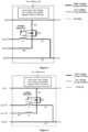
FIG. 2 is a circuit topology example 1 of the multi-motor high-voltage DC charging compatible adapter device according to an embodiment of the disclosure. -
FIG. 3 is a circuit topology example 2 of the multi-motor high-voltage DC charging compatible adapter device according to an embodiment of the disclosure. -
FIG. 4 is a circuit topology example 3 of the multi-motor high-voltage DC charging compatible adapter device according to an embodiment of the disclosure. -
FIG. 5 is a circuit topology example 4 of the multi-motor high-voltage DC charging compatible adapter device according to an embodiment of the disclosure. -
FIG. 6 through FIG. 9 are control flowcharts of the multi-motor high-voltage DC charging compatible adapter system according to an embodiment of the disclosure. -
FIG. 10 is a circuit topology example 1 of the multi-motor high-voltage DC charging compatible adapter system according to an embodiment of the disclosure. -
FIG. 11 is a circuit topology example 2 of the multi-motor high-voltage DC charging compatible adapter system according to an embodiment of the disclosure. -
FIG. 12 is a circuit topology example 3 of the multi-motor high-voltage DC charging compatible adapter system according to an embodiment of the disclosure. -
FIG. 13 is a circuit topology example 4 of the multi-motor high-voltage DC charging compatible adapter system according to an embodiment of the disclosure. - The disclosure will be further described below combined with accompanying drawings.
- Please refer to
FIG. 2 . In this embodiment, a multi-motor high-voltage DC charging compatible adapter device includes a high-voltage relay K1, a high-voltage relay K2, a high-voltage relay K3, a high-voltage relay K4, a resistor R3, capacitor C3, a high-voltage DC charging compatible adapter device controller, a high-voltage port and a low-voltage port, and a connection relationship is as follows: - the low-voltage port is connected with the high-voltage DC charging compatible adapter device controller, the low-voltage port comprises a low-voltage power supply port and a low-voltage communication port,
- the high-voltage port comprises a positive terminal in+ of a high-voltage DC input terminal, a negative terminal in- of a high-voltage DC input terminal, a positive terminal out+ of a high-voltage DC output terminal, a negative terminal out-A1 of a high-voltage DC output terminal, a negative terminal out-A2 of the high-voltage DC output terminal and a negative terminal out-B of the high-voltage DC output terminal, the positive terminal in+ of the high-voltage DC input terminal and the positive terminal out+ of the high-voltage DC output terminal are respectively connected with one end of the high-voltage relay K3, the other end of the high-voltage relay K3 is connected with the negative terminal out-A1 of the high-voltage DC output terminal through the resistor R3, the capacitor C3 and resistor R3 are connected in parallel, a connection point between the negative terminal out-A1 of the high-voltage DC output terminal and the resistor R3 is connected with the negative terminal out-A2 of the high-voltage DC output terminal through the high-voltage relay K4, the connection point between the negative terminal out-A1 of the high-voltage DC output terminal and the resistor R3 is further connected with the negative terminal out-B of the high-voltage DC output terminal through the high-voltage relay K1 and the high-voltage relay K2 successively, a connection point of the high-voltage relay K1 and the high-voltage relay K2 is connected with the negative terminal in- of the high-voltage DC input terminal,
- the high-voltage DC charging compatible adapter device controller is configured to be with communication functions, high-voltage relay K2 driving and control functions, high-voltage relay K1 driving and control functions, high-voltage relay K3 driving and control functions, high-voltage relay K4 driving and control functions, a capacitor C3 voltage detection function and a communication function, and a function of detecting a capacitor voltage UC3 and sending it out in real time through the low-voltage communication port, and the high-voltage DC charging compatible adapter device controller is respectively connected with control terminals of the high-voltage relay K1, the high-voltage relay K2, the high-voltage relay K3, and the high-voltage relay K4.
- Please refer to
FIG. 3 . In this embodiment, a multi-motor high-voltage DC charging compatible adapter device includes a high-voltage relay K1, a high-voltage relay K2, a high-voltage relay K3, a high-voltage relay K4, a resistor R3, capacitor C3, a high-voltage DC charging compatible adapter device controller, a high-voltage port, a low-voltage port and an inductor L1, and a specific connection relationship is as follows: - the low-voltage port is connected with the high-voltage DC charging compatible adapter device controller, the low-voltage port comprises a low-voltage power supply port and a low-voltage communication port,
- the high-voltage port comprises a positive terminal in+ of a high-voltage DC input terminal, a negative terminal in- of a high-voltage DC input terminal, a positive terminal out+ of a high-voltage DC output terminal, a negative terminal out-A1 of a high-voltage DC output terminal, a negative terminal out-A2 of the high-voltage DC output terminal and a negative terminal out-B of the high-voltage DC output terminal, the positive terminal in+ of the high-voltage DC input terminal and the positive terminal out+ of the high-voltage DC output terminal are respectively connected with one end of the high-voltage relay K3, the other end of the high-voltage relay K3 and the inductor L1 is connected with the negative terminal out-A1 of the high-voltage DC output terminal through the resistor R3, the capacitor C3 and resistor R3 are connected in parallel, a connection point between the inductor L1 and the resistor R3 is connected with the negative terminal out-A2 of the high-voltage DC output terminal through the high-voltage relay K4, the connection point between the inductor L1 and the resistor R3 is further connected with the negative terminal out-B of the high-voltage DC output terminal through the high-voltage relay K1 and the high-voltage relay K2 successively, a connection point of the high-voltage relay K1 and the high-voltage relay K2 is connected with the negative terminal in- of the high-voltage DC input terminal,
- the high-voltage DC charging compatible adapter device controller is configured to be with communication functions, high-voltage relay K2 driving and control functions, high-voltage relay K1 driving and control functions, high-voltage relay K3 driving and control functions, high-voltage relay K4 driving and control functions, a capacitor C3 voltage detection function and a communication function, and a function of detecting a capacitor voltage UC3 and sending it out in real time through the low-voltage communication port, and the high-voltage DC charging compatible adapter device controller is respectively connected with control terminals of the high-voltage relay K1, the high-voltage relay K2, the high-voltage relay K3, and the high-voltage relay K4.
- Please refer to
FIG. 4 . In this embodiment, a multi-motor high-voltage DC charging compatible adapter device includes a high-voltage relay K1, a high-voltage relay K2, a high-voltage relay K3, a high-voltage relay K4, a resistor R3, capacitor C3, a high-voltage DC charging compatible adapter device controller, a high-voltage port, a low-voltage port, an inductor L1 and an inductor L2, and a specific connection relationship is as follows: - the low-voltage port is connected with the high-voltage DC charging compatible adapter device controller, the low-voltage port comprises a low-voltage power supply port and a low-voltage communication port,
- the high-voltage port comprises a positive terminal in+ of a high-voltage DC input terminal, a negative terminal in- of a high-voltage DC input terminal, a positive terminal out+ of a high-voltage DC output terminal, a negative terminal out-A1 of a high-voltage DC output terminal, a negative terminal out-A2 of the high-voltage DC output terminal and a negative terminal out-B of the high-voltage DC output terminal, the positive terminal in+ of the high-voltage DC input terminal and the positive terminal out+ of the high-voltage DC output terminal are respectively connected with one end of the high-voltage relay K3, the other end of the high-voltage relay K3 and the inductor L1 is connected with the negative terminal out-A1 of the high-voltage DC output terminal through the resistor R3, the capacitor C3 and resistor R3 are connected in parallel, a connection point of the inductor L1 and the resistor R3 is connected with the negative terminal out-A2 of the high-voltage DC output terminal through the inductor L2, the high-voltage relay K4 successively, a connection point of the high-voltage relay K1 and the high-voltage relay K2 is connected with the negative terminal in- of the high-voltage DC input terminal,
- the high-voltage DC charging compatible adapter device controller is configured to be with communication functions, high-voltage relay K2 driving and control functions, high-voltage relay K1 driving and control functions, high-voltage relay K3 driving and control functions, high-voltage relay K4 driving and control functions, a capacitor C3 voltage detection function and a communication function, and a function of detecting a capacitor voltage UC3 and sending it out in real time through the low-voltage communication port, and the high-voltage DC charging compatible adapter device controller is respectively connected with control terminals of the high-voltage relay K1, the high-voltage relay K2, the high-voltage relay K3, and the high-voltage relay K4.
- Please refer to
FIG. 5 . In this embodiment, a multi-motor high-voltage DC charging compatible adapter device includes a high-voltage relay K1, a high-voltage relay K2, a high-voltage relay K3, a high-voltage relay K4, a resistor R3, capacitor C3, a high-voltage DC charging compatible adapter device controller, a high-voltage port, a low-voltage port and an inductor L2, and a specific connection relationship is as follows: - the low-voltage port is connected with the high-voltage DC charging compatible adapter device controller, the low-voltage port comprises a low-voltage power supply port and a low-voltage communication port,
- the high-voltage port comprises a positive terminal in+ of a high-voltage DC input terminal, a negative terminal in- of a high-voltage DC input terminal, a positive terminal out+ of a high-voltage DC output terminal, a negative terminal out-A1 of a high-voltage DC output terminal, a negative terminal out-A2 of the high-voltage DC output terminal and a negative terminal out-B of the high-voltage DC output terminal, the positive terminal in+ of the high-voltage DC input terminal and the positive terminal out+ of the high-voltage DC output terminal are respectively connected with one end of the high-voltage relay K3, the other end of the high-voltage relay K3 is connected with the negative terminal out-A1 of the high-voltage DC output terminal through the resistor R3, the capacitor C3 and resistor R3 are connected in parallel, a connection point between the negative terminal out-A1 of the high-voltage DC output terminal and the resistor R3 is connected with the negative terminal out-A2 of the high-voltage DC output terminal through the inductor L2 and the high-voltage relay K4 successively, the connection point between the negative terminal out-A1 of the high-voltage DC output terminal and the resistor R3 is further connected with the negative terminal out-B of the high-voltage DC output terminal through the high-voltage relay K1 and the high-voltage relay K2 successively, a connection point of the high-voltage relay K1 and the high-voltage relay K2 is connected with the negative terminal in- of the high-voltage DC input terminal,
- the high-voltage DC charging compatible adapter device controller is configured to be with communication functions, high-voltage relay K2 driving and control functions, high-voltage relay K1 driving and control functions, high-voltage relay K3 driving and control functions, high-voltage relay K4 driving and control functions, a capacitor C3 voltage detection function and a communication function, and a function of detecting a capacitor voltage UC3 and sending it out in real time through the low-voltage communication port, and the high-voltage DC charging compatible adapter device controller is respectively connected with control terminals of the high-voltage relay K1, the high-voltage relay K2, the high-voltage relay K3, and the high-voltage relay K4.
- Please refer to
FIG. 1 . In this embodiment, a multi-motor high-voltage DC charging compatible adapter system includes a firstelectric drive 10 and afirst controller 11, a secondelectric drive 20 and asecond controller 21, a battery and a battery controller, a vehicle controller and the multi-motor high-voltage DC charging compatible adapter device of the embodiment, and a specific connection relationship is as follows: - the positive terminal in+ of the high-voltage DC input terminal of the multi-motor high-voltage DC charging compatible adapter device is connected with a positive terminal + of the high-voltage DC charging port, the negative terminal in- of the high-voltage DC input terminal of the multi-motor high-voltage DC charging compatible adapter device is connected with a negative terminal - of the high-voltage DC charging port, the positive terminal out+ of the high-voltage DC output terminal of the multi-motor high-voltage DC charging compatible adapter device is connected with a third positive terminal +B of the battery controller, the negative terminal out-A1 of the high-voltage DC output terminal of the multi-motor high-voltage DC charging compatible adapter device is connected with a first motor neutral point terminal N1 of the first electric drive controller 11, the negative terminal out-A2 of the high-voltage DC output terminal of the multi-motor high-voltage DC charging compatible adapter device is connected with a second motor neutral point terminal N2 of the second electric drive controller 21, the negative terminal out-B of the high-voltage DC output terminal of the multi-motor high-voltage DC charging compatible adapter device is connected with a third negative terminal -B of the battery controller, a positive terminal + of the first electric drive controller 11 is connected with a first positive terminal +A1 of the battery controller, a negative terminal - of the first electric drive controller 11 is connected with a first negative terminal -A1 of the battery controller, a positive terminal (+) of the second electric drive controller 21 is connected with a second positive terminal +A2 of the battery controller, the negative terminal - of the second electric drive controller 21 is connected with a second negative terminal -A2 of the battery controller,
- the multi-motor high-voltage DC charging compatible adapter device is connected with the first
electric drive controller 11, the secondelectric drive controller 21, the battery controller and the vehicle controller through a low-voltage wiring harness, and when connecting a charging pile, the high-voltage DC input terminal of the multi-motor high-voltage DC charging compatible adapter device is connected with a high-voltage terminal of the charging pile, and the battery controller is connected with a charging pile controller through a low-voltage wiring harness. - Please refer to
FIG. 10. FIG. 10 is a circuit topology example 1 of the multi-motor high-voltage DC charging compatible adapter system in this embodiment. The topology example uses the multi-motor high-voltage DC charging compatible adapter device as shown inFIG. 2 . Wherein, the firstelectric drive 10 and theelectric drive 20 respectively adopt a system equivalent circuit topology of an electronically controlled three-phase bridge arm and a parallel operation mode of the corresponding three-phase winding of the motor. A detailed control logic of this topology example is executed according to the control method and operations of the multi-motor high-voltage DC charging compatible adapter device system shown inFIG. 10 . A buck mode: the high-voltage relay K1 and high-voltage relay K3 are connected, high-voltage relay K2 and high-voltage relay K4 are disconnected, a main positive relay of the battery and a main negative relay of the battery are connected, a power switch transistor S11 through a power switch transistor S13 are disconnected, a power switch transistor S21 through a power switch through S26 are disconnected, a power switch transistor S14 through a power switch transistor S16 run in the buck mode to realize an buck operation of the battery through the electric drive to the capacitor of the charging port. A boost mode: the high voltage relay K1 and the high voltage relay K4 are connected (switched on), the high voltage relay K2 is disconnected(switched off), the main positive relay and the main negative relay of the battery are connected, the power switch transistor S14 through the power switch transistor S16 are disconnected, the power switch transistor S24 through the power switch transistor S26 are disconnected, the power switch transistor S11 through power switch transistor S13 and the power switch transistor S21 through power switch transistor S23 run in the boost mode, so as to realize a boost operation from the charging port to the battery through the electric drive. A direct charging mode: the high voltage relay K2 is connected, the high voltage relay K1, the high voltage relay K3, and the high voltage relay K4 are disconnected, the main positive relay and the main negative relay of the battery are connected, the power switch transistor S11 through the power switch transistor S16 are disconnected, the power switch transistor S21 through the power switch transistor S26 are disconnected to operate in the direct charging mode, so as to realize a direct charging operation from the charging port to the battery. - Please refer to
FIG. 11 , which is a circuit topology example 2 of the multi-motor high-voltage DC charging compatible adapter system in this embodiment. The topology example uses the multi-motor high-voltage DC charging compatible adapter device as shown inFIG. 3 . The firstelectric drive 10 and the secondelectric drive 20 respectively adopt the system equivalent circuit topology of the electronically controlled three-phase bridge arm and the parallel operation mode of the corresponding three-phase winding of the motor. A detailed control logic of this topology example is executed according to the control method and operations of the multi-motor high-voltage DC charging compatible adapter device system shown inFIG. 12 . The buck mode: the high-voltage relay K1 and high-voltage relay K3 are connected, high-voltage relay K2 and high-voltage relay K4 are disconnected, the main positive relay of the battery and the main negative relay of the battery are connected, the power switch transistor S11 through the power switch transistor S13, the power switch transistor S21 through the power switch through S26 are disconnected, the power switch transistor S14 through the power switch transistor S16 run in the buck mode to realize the operation of the battery through the electric drive to the capacitor of the charging port. The boost mode: the high voltage relay K1 and the high voltage relay K4 are connected, the high voltage relay K2 is disconnected, the main positive relay and the main negative relay of the battery are connected, the power switch transistor S14 through the power switch transistor S16, the power switch transistor S24 through the power switch transistor S26 are disconnected, the power switch transistor S11 through power switch transistor S13 and the power switch transistor S21 through power switch transistor S23 run in the boost mode, so as to realize the boost operation from the charging port to the battery through the electric drive. The direct charging mode: the high voltage relay K2 is connected, the high voltage relay K1, the high voltage relay K3, and the high voltage relay K4 are disconnected, the main positive relay and the main negative relay of the battery are connected, the power switch transistor S11 through the power switch transistor S16, the power switch transistor S21 through the power switch transistor S26 are disconnected to operate in the direct charging mode, so as to realize the direct charging operation from the charging port to the battery. - Please refer to
FIG. 12 , which is a circuit topology example 3 of the multi-motor high-voltage DC charging compatible adapter system in this embodiment. The topology example uses the multi-motor high-voltage DC charging compatible adapter device as shown inFIG. 4 . Wherein, the firstelectric drive 10 and the secondelectric drive 20 respectively adopt the system equivalent circuit topology of the electronically controlled three-phase bridge arm and the parallel operation mode of the corresponding three-phase winding of the motor. A detailed control logic of this topology example is executed according to the control method and operations of the multi-motor high-voltage DC charging compatible adapter device system shown inFIG. 5 . The buck mode: the high-voltage relay K1 and high-voltage relay K3 are connected, high-voltage relay K2 and high-voltage relay K4 are disconnected, the main positive relay of the battery and the main negative relay of the battery are connected, the power switch transistor S11 through the power switch transistor S13, the power switch transistor S21 through the power switch through S26 are disconnected, the power switch transistor S14 through the power switch transistor S16 run in the buck mode to realize the operation of the battery through the electric drive to the capacitor of the charging port. The boost mode: the high voltage relay K1 and the high voltage relay K4 are connected, the high voltage relay K2 is disconnected, the main positive relay and the main negative relay of the battery are connected, the power switch transistor S14 through the power switch transistor S16, the power switch transistor S24 through the power switch transistor S26 are disconnected, the power switch transistor S11 through power switch transistor S13 and the power switch transistor S21 through power switch transistor S23 run in the boost mode, so as to realize the boost operation from the charging port to the battery through the electric drive. The direct charging mode: the high voltage relay K2 is connected, the high voltage relay K1, the high voltage relay K3, and the high voltage relay K4 are disconnected, the main positive relay and the main negative relay of the battery are connected, the power switch transistor S11 through the power switch transistor S16, the power switch transistor S21 through the power switch transistor S26 are disconnected to operate in the direct charging mode, so as to realize the direct charging operation from the charging port to the battery. - Please refer to
FIG. 13 , which is a circuit topology example 3 of the multi-motor high-voltage DC charging compatible adapter system in this embodiment. The topology example uses the multi-motor high-voltage DC charging compatible adapter device as shown inFIG. 4 . The topology example uses the multi-motor high-voltage DC charging compatible adapter device as shown inFIG. 4 . Wherein, the firstelectric drive 10 and the secondelectric drive 20 respectively adopt the system equivalent circuit topology of the electronically controlled three-phase bridge arm and the parallel operation mode of the corresponding three-phase winding of the motor. A detailed control logic of this topology example is executed according to the control method and operations of the multi-motor high-voltage DC charging compatible adapter device system shown inFIG. 5 . The buck mode: the high-voltage relay K1 and high-voltage relay K3 are connected, high-voltage relay K2 and high-voltage relay K4 are disconnected, the main positive relay of the battery and the main negative relay of the battery are connected, the power switch transistor S11 through the power switch transistor S13, the power switch transistor S21 through the power switch through S26 are disconnected, the power switch transistor S14 through the power switch transistor S16 run in the buck mode to realize the operation of the battery through the electric drive to the capacitor of the charging port. The boost mode: the high voltage relay K1 and the high voltage relay K4 are connected, the high voltage relay K2 is disconnected, the main positive relay and the main negative relay of the battery are connected, the power switch transistor S14 through the power switch transistor S16, the power switch transistor S24 through the power switch transistor S26 are disconnected, the power switch transistor S11 through power switch transistor S13 and the power switch transistor S21 through power switch transistor S23 run in the boost mode, so as to realize the boost operation from the charging port to the battery through the electric drive. The direct charging mode: the high voltage relay K2 is connected, the high voltage relay K1, the high voltage relay K3, and the high voltage relay K4 are disconnected, the main positive relay and the main negative relay of the battery are connected, the power switch transistor S11 through the power switch transistor S16, the power switch transistor S21 through the power switch transistor S26 are disconnected to operate in the direct charging mode, so as to realize the direct charging operation from the charging port to the battery. - Please refer to
FIG. 6 through FIG. 9 . In this embodiment, a control method of a multi-motor high-voltage DC charging compatible adapter system uses the multi-motor high-voltage DC charging compatible adapter system of the embodiment, after the multi-motor high-voltage DC charging compatible adapter system connected with a high-voltage DC charging pile, the control method includes following operations: - operation 1: connecting the high-voltage DC charging port with the high-voltage DC charging pile;
- operation 2: S201: detecting, by the battery controller, whether physically connecting the charging pile successfully, if yes, S202: powering on, matching a low-voltage auxiliary power supply, and entering
operation 3, otherwise returning to S201 continue the detection; - operation 3: S301: detecting, by the battery controller, whether receiving a handshake message of the charging pile, if yes, S302: sending a charging handshake message to the charging pile, including a maximum allowable total charging voltage of the battery, and entering
operation 4, otherwise returning to S301 continue the detection, if timeout expires, reporting a fault prompt and stopping the charging; - operation 4: S401: detecting, by the battery controller, whether receiving a 0x00 identification message of the charging pile, if yes, S402: sending the identification message of the battery controller and vehicle controller to the charging pile, including battery information and protocol version, and entering operation 5, otherwise returning to S401 continue the detection, if timeout expires, reporting a fault prompt and stopping the charging;
- operation 5: S501: detecting, by the battery controller, whether receiving a 0x00 identification message of the charging pile, if yes, S502: stopping sending the identification messages of the battery controller and the vehicle controller to the charging pile, and starting to send charging parameter messages of the battery to the charging pile including a maximum allowable charging voltage, a maximum allowable charging current, and a current battery voltage, when the current battery voltage being min [the current voltage of the battery-10V, 450V] (a minimum of a range between the current voltage of the battery-10V and 450V), entering operation 6, otherwise returning to continue S402 to send the identification messages of the battery controller and the vehicle controller to the charging pile, if timeout expires, reporting a fault prompt and stopping the charging;
- operation 6: S601: detecting, by the battery controller, whether receiving a message of a charging pile time synchronization and maximum output capacity, including charging pile time synchronization information, maximum output voltage, minimum output voltage, maximum output current, minimum output current, if yes, S602: stopping sending the parameter messages of the battery to the charging pile, starting to send a message that the vehicle is not ready for charging to the charging pile, and entering operation 7, otherwise reporting a fault prompt and stopping the charging;
- operation 7: S701: determining, by the battery controller, whether the charging pile parameters are appropriate, if yes, S702: sending a control command to the multi-motor high-voltage DC charging compatible adapter device controller, the first
electric drive controller 11, and the secondelectric drive controller 21 respectively through the vehicle controller, controlling the high-voltage relays K1 and K3 of the high-voltage DC charging compatible adapter device to close successively, then controlling a main positive relay and main negative relay of the battery to close, then controlling the secondelectric drive 20 to power on and stand by, controlling the firstelectric drive 10 to run in a buck mode, and buck outputting and setting the target voltage UC3R of capacitor C3 as the min [the current voltage of the battery-10V, 450V] (minimum of a range between the current voltage of the battery-10V and 450V); - operation 8: S801: determining, by the battery controller, whether a measured voltage UC3 of the capacitor C3 is within ±5% of the target voltage UC3R, if yes, S802: sending a charging ready message of the vehicle to the charging pile, and entering operation 9, otherwise returning to S801 continue the detection, if timeout expires, reporting a fault prompt and stopping the charging;
- operation 9: S901: determining, by the battery controller, whether receiving the charging ready message of the charging pile, if yes, S902: stopping to send the charging ready message of the vehicle to the charging pile, and entering
operation 10, otherwise returning to S901 continue the detection, if timeout expires, reporting a fault prompt and stopping the charging; - operation 10: determining, by the battery controller, whether the maximum allowable output voltage of the charging pile is less than or equal to 500V, if yes, entering
operation 11, otherwise skipping to operation 18; - operation 11: sending a charging demand message and a battery charging overall status message of the battery, by the battery controller, to the charging pile, the charging demand message of the battery including a charging required voltage and charging required current of the battery, requiring a voltage to be min [the current voltage of the battery -10V, 450V] (the minimum of a range between the current voltage of the battery -10V and 450V), and requiring a current to be min [20A, the charging required current of the battery] (a minimum of a range between 20A and the charging required current of the battery);
- operation 12: sending the control command, by the battery controller, to the multi-motor high-voltage DC charging compatible adapter device controller, the first
electric drive controller 11, and the secondelectric drive controller 21 through the vehicle controller, controlling the high-voltage relays K1 and K3 of the high-voltage DC charging compatible adapter device to keep closed, then controlling the relay K4 to close, then controlling the main positive relay and main negative relay of the battery to close, then controlling the firstelectric drive 10 and secondelectric drive 20 to be powered on at the same time and operate in a boost mode, and boost outputting and setting the target voltage UCR of the battery as min [the current voltage of the battery-10V, 450V] (the minimum of a range between the current voltage of the battery-10V and 450V); - operation 13: sending the control command to the multi-motor high-voltage DC charging compatible adapter device controller through the vehicle controller after the battery controller detects that the boost mode of the electric drive runs for 1 minute, and controlling the high-voltage relay K3 of the high-voltage DC charging compatible adapter device to disconnect;
- operation 14: S1401: detecting, by the battery controller, whether the output current of the charging pile is greater than 5A, if yes, S1402: adjusting parameters of the charging demand message of the battery, and adjusting the required voltage to rise from 5V/s to min [the maximum allowable total charging voltage of the battery -10V, a maximum allowable total charging voltage of the charging pile -10V] (the minimum of a range between the maximum allowable total charging voltage of the battery -10V and a maximum allowable total charging voltage of the charging pile -10V), requiring the current to be min [20A, the charging demand current of the battery] (the minimum of a range between 20A and the charging demand current of the battery), and then entering
operation 15, otherwise returning to S1401 continue to the detection; - operation 15: S1501: detecting, by the battery controller, whether the output voltage of the charging pile is equal to min [the maximum allowable total charging voltage of the battery -10V, the maximum allowable total charging voltage of the charging pile -10V] (the minimum of a range between the maximum allowable total charging voltage of the battery -10V and a maximum allowable total charging voltage of the charging pile -10V), if yes, S1502: adjusting parameters of the charging demand message of the battery, adjusting the required voltage to keep at min [the maximum allowable total charging voltage of the battery -10V, the maximum allowable total charging voltage of the charging pile -10V] (the minimum of a range between the maximum allowable total charging voltage of the battery -10V and a maximum allowable total charging voltage of the charging pile -10V), adjusting the required current to be min [a maximum allowable outputting current of the charging pile, a charging required current of battery] (the minimum of a range between the maximum allowable outputting current of the charging pile and the charging required current of battery), and then entering
operation 16, otherwise returning to S1501 continue the detection; - operation 16: S1601: detecting, by the battery controller, whether the battery is fully charged, if yes, S1602: adjusting parameters of the charging demand message of the battery, adjusting the required voltage to keep at min [the maximum allowable total charging voltage of the battery -10V, the maximum allowable total charging voltage of the charging pile -10V] (the minimum of a range between the maximum allowable total charging voltage of the battery -10V and the maximum allowable total charging voltage of the charging pile -10V), adjusting the current to be 0A, and then entering operation 17, otherwise returning to continue the charging;
- operation 17: S1701: detecting, by the battery controller, whether the output current of the charging pile is equal to 0A, if yes, S1702: sending the control command to the battery controller, multi-motor high-voltage DC charging compatible adapter device controller, first
electric drive controller 11, and secondelectric drive controller 21 through the vehicle controller, controlling the main positive relay and main negative relay of the battery to disconnect, then controlling the firstelectric drive 10 and secondelectric drive 20 to run in no mode, then sending charging statistic information, and then ending the charging; - operation 18: S1801: detecting, by the battery controller, whether the maximum allowable output voltage of the charging pile is greater than 500V, if yes, S1802: sending the charging demand message of the battery and a charging general state message of the battery to the charging pile, the charging demand message of the battery including the charging required voltage of the battery and the charging required current of the battery, requiring the voltage to be the current voltage of the battery and requiring the current to be min [20A, the charging required current of the battery] (the minimum of a range between 20A and the charging required current of the battery);
- operation 19: sending the control command, by the battery controller, to the multi-motor high-voltage DC charging compatible adapter device controller, first
electric drive controller 11, and secondelectric drive controller 21 respectively through the vehicle controller, controlling the high-voltage relays K1 and K3 of the multi-motor high-voltage DC charging compatible adapter device remain closed, then controlling the relay K4 to close, then controlling the main positive relay and the main negative relay of the battery to close, then controlling the firstelectric drive 10 and secondelectric drive 20 to power on at the same time and run in the boost mode, boost outputting and setting the target voltage UCR of the battery as the current voltage of the battery +10V; - operation 20: S2001: detecting, by the battery controller, whether the output voltage of the charging pile is equal to the current voltage of the battery, if yes, S2002: adjusting the parameters of the charging demand message of the battery, requiring the voltage to be kept at the current voltage of the battery, adjusting the required current to be 0A, and then entering
operation 21, otherwise returning to S2001 continue the detection; - operation 21: S2101: detecting, by the battery controller, whether the output current of the charging pile is equal to 0A, if yes, S2102: sending the control command to the multi-motor high-voltage DC charging compatible adapter device controller, first
electric drive controller 11, and secondelectric drive controller 21 through the vehicle controller, controlling the high-voltage relay K1, high-voltage relay K3, and high-voltage relay K4 of the multi-motor high-voltage DC charging compatible adapter device to disconnect successively, then controlling the firstelectric drive 10 and secondelectric drive 20 to run in no mode, then controlling the high-voltage relay K2 of the multi-motor high-voltage DC charging compatible adapter device to close, and switching to a direct charging mode; - operation 22: S2201: detecting, by the battery controller, whether the battery is fully charged, if yes, S2202: adjusting parameters of the charging demand message of the battery, adjusting the required voltage to keep at min [the maximum allowable total charging voltage of the battery -10V, the maximum allowable total charging voltage of the charging pile -10V] (the minimum of a range between the maximum allowable total charging voltage of the battery -10V and the maximum allowable total charging voltage of the charging pile -10V), adjusting the current to be 0A, and then entering
operation 23, otherwise returning to continue the charging; - operation 23: S2301: detecting, by the battery controller, whether the output current of the charging pile is equal to 0A, if yes, S2302: sending the control command to the battery controller and the multi-motor high-voltage DC charging compatible adapter device controller, controlling the main positive relay and main negative relay of the battery to disconnect, then controlling the high-voltage relay K2 of the multi-motor high-voltage DC charging compatible adapter device to disconnect, then sending charging statistic information, and then ending the charging.
- The above-mentioned embodiment is a preferred embodiment of the method of the disclosure, but the embodiment of the method of the disclosure is not limited by the above-mentioned embodiment. Any other changes, modifications, substitutions, combinations, and simplifications that do not deviate from the spirit and principles of the disclosure shall be equivalent replacement methods and shall be included within the protection scope of the disclosure.
Claims (7)
- A multi-motor high-voltage DC charging compatible adapter device, comprising a high-voltage relay K1, a high-voltage relay K2, a high-voltage relay K3, a high-voltage relay K4, a resistor R3, a capacitor C3, a high-voltage DC charging compatible adapter device controller, a high-voltage port and a low-voltage port,
whereinthe low-voltage port is connected with the high-voltage DC charging compatible adapter device controller, the low-voltage port comprises a low-voltage power supply port and a low-voltage communication port,the high-voltage port comprises a positive terminal in+ of a high-voltage DC input terminal, a negative terminal in- of the high-voltage DC input terminal, a positive terminal out+ of a high-voltage DC output terminal, a negative terminal out-A1 of the high-voltage DC output terminal, a negative terminal out-A2 of the high-voltage DC output terminal and a negative terminal out-B of the high-voltage DC output terminal; the positive terminal in+ of the high-voltage DC input terminal and the positive terminal out+ of the high-voltage DC output terminal are respectively connected with a first end of the high-voltage relay K3, a second end of the high-voltage relay K3 is connected with the negative terminal out-A1 of the high-voltage DC output terminal through the resistor R3, the capacitor C3 and the resistor R3 are connected in parallel, a connection point between the negative terminal out-A1 of the high-voltage DC output terminal and the resistor R3 is connected with the negative terminal out-A2 of the high-voltage DC output terminal through the high-voltage relay K4, the connection point between the negative terminal out-A1 of the high-voltage DC output terminal and the resistor R3 is further connected with the negative terminal out-B of the high-voltage DC output terminal through the high-voltage relay K1 and the high-voltage relay K2 successively, a connection point of the high-voltage relay K1 and the high-voltage relay K2 is connected with the negative terminal in- of the high-voltage DC input terminal,the high-voltage DC charging compatible adapter device controller is configured to be with communication functions, high-voltage relay K2 driving and control functions, high-voltage relay K1 driving and control functions, high-voltage relay K3 driving and control functions, high-voltage relay K4 driving and control functions, capacitor C3 voltage detection and communication functions, and a function of detecting a capacitor voltage UC3 and sending it out in real time through the low-voltage communication port, and the high-voltage DC charging compatible adapter device controller is respectively connected with control terminals of the high-voltage relay K1, the high-voltage relay K2, the high-voltage relay K3, and the high-voltage relay K4. - The multi-motor high-voltage DC charging compatible adapter device according to claim 1,further comprising an inductor L1, wherein
the second end of the high-voltage relay K3 is connected with the negative terminal out-A1 of the high-voltage DC output terminal through the resistor R3 and the inductor L1, a connection point between the inductor L1 and the resistor R3 is connected with the negative terminal out-A2 of the high-voltage DC output terminal through the high-voltage relay K4, the connection point between the inductor L1 and the resistor R3 is further connected with the negative terminal out-B of the high-voltage DC output terminal through the high-voltage relay K1 and the high-voltage relay K2 successively. - The multi-motor high-voltage DC charging compatible adapter device according to claim 1, further comprising an inductor L1 and an inductor L2, wherein
the second end of the high-voltage relay K3 is connected with the negative terminal out-A1 of the high-voltage DC output terminal through the resistor R3 and the inductor L1, a connection point of the inductor L1 and the resistor R3 is connected with the negative terminal out-A2 of the high-voltage DC output terminal through the inductor L2, the high-voltage relay K4 successively, the connection point between the inductor L1 and the resistor R3 is further connected with the negative terminal out-B of the high-voltage DC output terminal through the high-voltage relay K1 and the high-voltage relay K2 successively. - The multi-motor high-voltage DC charging compatible adapter device according to claim 1, further comprising an inductor L2, wherein
a connection point between the negative terminal out-A1 of the high-voltage DC output terminal and the resistor R3 is connected with the negative terminal out-A2 of the high-voltage DC output terminal through the inductor L2 and the high-voltage relay K4 successively. - The multi-motor high-voltage DC charging compatible adapter system, further comprising a first electric drive (10) and a first controller (11), a second electric drive (20) and a second controller (21), a battery and a battery controller, a vehicle controller and the multi-motor high-voltage DC charging compatible adapter device according to any one of claim 1 to claim 4, whereinthe positive terminal in+ of the high-voltage DC input terminal of the multi-motor high-voltage DC charging compatible adapter device is connected with a positive terminal (+) of the high-voltage DC charging port, the negative terminal in- of the high-voltage DC input terminal of the multi-motor high-voltage DC charging compatible adapter device is connected with a negative terminal (-) of the high-voltage DC charging port, the positive terminal out+ of the high-voltage DC output terminal of the multi-motor high-voltage DC charging compatible adapter device is connected with a third positive terminal (+B) of the battery controller, the negative terminal out-A1 of the high-voltage DC output terminal of the multi-motor high-voltage DC charging compatible adapter device is connected with a first motor neutral point terminal (N1) of the first electric drive controller (11), the negative terminal out-A2 of the high-voltage DC output terminal of the multi-motor high-voltage DC charging compatible adapter device is connected with a second motor neutral point terminal (N2) of the second electric drive controller (21), the negative terminal out-B of the high-voltage DC output terminal of the multi-motor high-voltage DC charging compatible adapter device is connected with a third negative terminal (-B) of the battery controller, a positive terminal (+) of the first electric drive controller (11) is connected with a first positive terminal (+A1) of the battery controller, a negative terminal (-) of the first electric drive controller (11) is connected with a first negative terminal (-A1) of the battery controller, a positive terminal (+) of the second electric drive controller (21) is connected with a second positive terminal (+A2) of the battery controller, the negative terminal (-) of the second electric drive controller (21) is connected with a second negative terminal (-A2) of the battery controller,the multi-motor high-voltage DC charging compatible adapter device is connected with the first electric drive controller (11), the second electric drive controller (21), the battery controller and the vehicle controller through a low-voltage wiring harness, and when connecting a charging pile, the high-voltage DC input terminal of the multi-motor high-voltage DC charging compatible adapter device is connected with a high-voltage terminal of the charging pile, and the battery controller is connected with a charging pile controller through a low-voltage wiring harness.
- A control method of a multi-motor high-voltage DC charging compatible adapter system, using the multi-motor high-voltage DC charging compatible adapter system according to any one of claim 1 to claim 8, after the multi-motor high-voltage DC charging compatible adapter system connected with a high-voltage DC charging pile, the control method comprising:operation 1: connecting the high-voltage DC charging port with the high-voltage DC charging pile;operation 2: detecting, by the battery controller, whether physically connecting the charging pile successfully, if yes, powering on, matching a low-voltage auxiliary power supply, and entering operation 3, otherwise returning to continue the detection of operation 2;operation 3: detecting, by the battery controller, whether receiving a handshake message of the charging pile, if yes, sending a charging handshake message to the charging pile, including a maximum allowable total charging voltage of the battery, and entering operation 4, otherwise returning to continue the detection of operation 3, if timeout expires, reporting a fault prompt and stopping the charging;operation 4: detecting, by the battery controller, whether receiving an identification message of the charging pile, if yes, sending the identification message of the battery controller and vehicle controller to the charging pile, including battery information and protocol version, and entering operation 5, otherwise returning to continue the detection of operation 4, if timeout expires, reporting a fault prompt and stopping the charging;operation 5: detecting, by the battery controller, whether receiving an identification message of the charging pile, if yes, stopping sending the identification messages of the battery controller and the vehicle controller to the charging pile, and starting to send charging parameter messages of the battery to the charging pile including a maximum allowable charging voltage, a maximum allowable charging current, and a current battery voltage, when the current battery voltage being min [the current voltage of the battery minus 10V, 450V], entering operation 6, otherwise returning to continue to send the identification messages of the battery controller and the vehicle controller to the charging pile, if timeout expires, reporting a fault prompt and stopping the charging;operation 6: detecting, by the battery controller, whether receiving a message of a charging pile time synchronization and maximum output capacity, including charging pile time synchronization information, maximum output voltage, minimum output voltage, maximum output current, minimum output current, if yes, stopping sending the parameter messages of the battery to the charging pile, starting to send a message that the vehicle is not ready for charging to the charging pile, and entering operation 7, otherwise reporting a fault prompt and stopping the charging;operation 7: determining, by the battery controller, whether the charging pile parameters are appropriate, if yes, sending a control command to the multi-motor high-voltage DC charging compatible adapter device controller, the first electric drive controller (11), and the second electric drive controller (21) respectively through the vehicle controller, controlling the high-voltage relays K1 and K3 of the high-voltage DC charging compatible adapter device to turn on successively, then controlling a main positive relay and a main negative relay of the battery to turn on, then controlling the second electric drive (20) to power on and stand by, controlling the first electric drive (10) to run in a buck mode, and buck outputting and setting a target voltage UC3R of capacitor C3 as the min [the current voltage of the battery-10V, 450V];operation 8: determining, by the battery controller, whether a measured voltage UC3 of the capacitor C3 is within ±5% of the target voltage UC3R, if yes, sending a charging ready message of the vehicle to the charging pile, and entering operation 9, otherwise returning to continue the detection of operation 8, if timeout expires, reporting a fault prompt and stopping the charging;operation 9: determining, by the battery controller, whether receiving the charging ready message of the charging pile, if yes, stopping to send the charging ready message of the vehicle to the charging pile, and entering operation 10, otherwise returning to continue the detection of operation 9, if timeout expires, reporting a fault prompt and stopping the charging;operation 10: determining, by the battery controller, whether the maximum allowable output voltage of the charging pile is less than or equal to 500V, if yes, entering operation 11, otherwise skipping to operation 18;operation 11: sending a charging demand message and a battery charging overall status message of the battery, by the battery controller, to the charging pile, the charging demand message of the battery including a charging required voltage and charging required current of the battery, the required voltage to be min [the current voltage of the battery -10V, 450V], and the required current to be min [20A, the charging required current of the battery];operation 12: sending the control command, by the battery controller, to the multi-motor high-voltage DC charging compatible adapter device controller, the first electric drive controller (11), and the second electric drive controller (21) through the vehicle controller, controlling the high-voltage relays K1 and K3 of the high-voltage DC charging compatible adapter device to keep closed, then controlling the relay K4 to close, then controlling the main positive relay and main negative relay of the battery to close, then controlling the first electric drive (10) and the electric drive (20) to be powered on at the same time and operate in a boost mode, and boost outputting and setting the target voltage UCR of the battery as min [the current voltage of the battery-10V, 450V];operation 13: sending the control command to the multi-motor high-voltage DC charging compatible adapter device controller through the vehicle controller after the battery controller detects that the boost mode of the electric drive runs for 1 minute, and controlling the high-voltage relay K3 of the high-voltage DC charging compatible adapter device to disconnect;operation 14: detecting, by the battery controller, whether the output current of the charging pile is greater than 5A, if yes, adjusting parameters of the charging demand message of the battery, and adjusting the required voltage to rise to min [the maximum allowable total charging voltage of the battery -10V, a maximum allowable total charging voltage of the charging pile -10V] at a speed of 5V/s, the required current remains to be min [20A, the charging demand current of the battery], and then entering operation 15, otherwise returning to continue to the detection of operation 14;operation 15: detecting, by the battery controller, whether the output voltage of the charging pile is equal to min [the maximum allowable total charging voltage of the battery -10V, the maximum allowable total charging voltage of the charging pile -10V], if yes, adjusting parameters of the charging demand message of the battery, adjusting the required voltage to keep at min [the maximum allowable total charging voltage of the battery -10V, the maximum allowable total charging voltage of the charging pile -10V], adjusting the required current to be min [a maximum allowable outputting current of the charging pile, a charging required current of battery], and then entering operation 16, otherwise returning to continue the detection of operation 15;operation 16: detecting, by the battery controller, whether the battery is fully charged, if yes, adjusting parameters of the charging demand message of the battery, adjusting the required voltage to keep at min [the maximum allowable total charging voltage of the battery -10V, the maximum allowable total charging voltage of the charging pile -10V], adjusting the current to be 0A, and then entering operation 17, otherwise returning to continue the charging;operation 17: detecting, by the battery controller, whether the output current of the charging pile is equal to 0A, if yes, sending the control command to the battery controller, multi-motor high-voltage DC charging compatible adapter device controller, the first electric drive controller (11), and the second electric drive controller (21) through the vehicle controller, controlling the main positive relay and main negative relay of the battery to turn off, then controlling the first electric drive (10) and the electric drive (20) to run in no mode, then sending charging statistic information, and then ending the charging;operation 18: detecting, by the battery controller, whether the maximum allowable output voltage of the charging pile is greater than 500V, if yes, sending the charging demand message of the battery and a charging general state message of the battery to the charging pile, the charging demand message of the battery including the charging required voltage of the battery and the charging required current of the battery, the required voltage to be the current voltage of the battery and the required current to be min [20A, the charging required current of the battery];operation 19: sending the control command, by the battery controller, to the multi-motor high-voltage DC charging compatible adapter device controller, the first electric drive controller (11), and the second electric drive controller (21) respectively through the vehicle controller, controlling the high-voltage relays K1 and K3 of the multi-motor high-voltage DC charging compatible adapter device remain closed, then controlling the relay K4 to close, then controlling the main positive relay and the main negative relay of the battery to close, then controlling the first electric drive (10) and the second electric drive (20) to power on at the same time and run in the boost mode, boost outputting and setting the target voltage UCR of the battery as the current voltage of the battery +10V;operation 20: detecting, by the battery controller, whether the output voltage of the charging pile is equal to the current voltage of the battery, if yes, adjusting the parameters of the charging demand message of the battery, the required voltage to be kept at the current voltage of the battery, adjusting the required current to be 0A, and then entering operation 21, otherwise returning to continue the detection of operation 20;operation 21: detecting, by the battery controller, whether the output current of the charging pile is equal to 0A, if yes, sending the control command to the multi-motor high-voltage DC charging compatible adapter device controller, the first electric drive controller (11), and the second electric drive controller (21) through the vehicle controller, controlling the high-voltage relay K1, high-voltage relay K3, and high-voltage relay K4 of the multi-motor high-voltage DC charging compatible adapter device to disconnect successively, then controlling the first electric drive (10) and the second electric drive (20) to run in no mode, then controlling the high-voltage relay K2 of the multi-motor high-voltage DC charging compatible adapter device to close, and switching to a direct charging mode;operation 22: detecting, by the battery controller, whether the battery is fully charged, if yes, adjusting parameters of the charging demand message of the battery, adjusting the required voltage to keep at min [the maximum allowable total charging voltage of the battery -10V, the maximum allowable total charging voltage of the charging pile -10V], adjusting the current to be 0A, and then entering operation 23, otherwise returning to continue the charging;operation 23: detecting, by the battery controller, whether the output current of the charging pile is equal to 0A, if yes, sending the control command to the battery controller and the multi-motor high-voltage DC charging compatible adapter device controller, controlling the main positive relay and main negative relay of the battery to disconnect, then controlling the high-voltage relay K2 of the multi-motor high-voltage DC charging compatible adapter device to disconnect, then sending charging statistic information, and ending the charging.
- An automobile, comprising the multi-motor high-voltage DC charging compatible adapter system according to any one of claims 1 to 6.
Applications Claiming Priority (1)
| Application Number | Priority Date | Filing Date | Title |
|---|---|---|---|
| CN202210682378.9A CN115001097B (en) | 2022-06-16 | 2022-06-16 | Multi-motor high-voltage DC charging compatible adapter device, system and control method, vehicle |
Publications (2)
| Publication Number | Publication Date |
|---|---|
| EP4303068A2 true EP4303068A2 (en) | 2024-01-10 |
| EP4303068A3 EP4303068A3 (en) | 2024-03-06 |
Family
ID=83034485
Family Applications (1)
| Application Number | Title | Priority Date | Filing Date |
|---|---|---|---|
| EP23162198.8A Pending EP4303068A3 (en) | 2022-06-16 | 2023-03-15 | Multi-motor high-voltage dc charging compatible adapter device, system and control method, and automobile |
Country Status (2)
| Country | Link |
|---|---|
| EP (1) | EP4303068A3 (en) |
| CN (1) | CN115001097B (en) |
Families Citing this family (2)
| Publication number | Priority date | Publication date | Assignee | Title |
|---|---|---|---|---|
| CN116394771A (en) * | 2023-03-14 | 2023-07-07 | 重庆长安新能源汽车科技有限公司 | Vehicle-mounted multi-motor DC charging system, control method, device, equipment and medium |
| CN118928138B (en) * | 2024-08-29 | 2025-09-05 | 重庆长安汽车股份有限公司 | Charging method, device, vehicle controller, battery controller and electric vehicle |
Family Cites Families (10)
| Publication number | Priority date | Publication date | Assignee | Title |
|---|---|---|---|---|
| US11479139B2 (en) * | 2015-09-11 | 2022-10-25 | Invertedpower Pty Ltd | Methods and systems for an integrated charging system for an electric vehicle |
| EP3347963A4 (en) * | 2015-09-11 | 2019-01-16 | Invertedpower Pty Ltd | CONTROLLER FOR INDUCTIVE LOAD HAVING ONE OR MORE INDUCTIVE WINDINGS |
| US10507716B2 (en) * | 2016-04-25 | 2019-12-17 | General Electric Company | Integrated charger for vehicles and method of making same |
| DE102017201350B4 (en) * | 2017-01-27 | 2018-03-22 | Continental Automotive Gmbh | Method for transmitting electrical energy between a vehicle-side energy storage and a connection station and vehicle electrical system |
| US11801763B2 (en) * | 2017-12-19 | 2023-10-31 | Ford Global Technologies, Llc | Integrated DC vehicle charger |
| DE102019200996A1 (en) * | 2019-01-28 | 2020-07-30 | Robert Bosch Gmbh | Electrical circuit arrangement and method for operating such a circuit arrangement |
| CN111873830B (en) * | 2020-09-11 | 2022-10-25 | 北京理工大学 | Distributed dual-motor driving and vehicle-mounted charging integrated system for electric automobile and charging control method thereof |
| CN112848932B (en) * | 2021-01-15 | 2022-05-31 | 重庆长安新能源汽车科技有限公司 | Control method and control system for direct current charging of electric automobile |
| CN113022344B (en) * | 2021-04-30 | 2022-05-31 | 重庆长安新能源汽车科技有限公司 | Power battery charging system based on double motors and electric automobile |
| CN215300205U (en) * | 2021-05-31 | 2021-12-24 | 广州汽车集团股份有限公司 | An electric vehicle buck-boost charging system and electric vehicle |
-
2022
- 2022-06-16 CN CN202210682378.9A patent/CN115001097B/en active Active
-
2023
- 2023-03-15 EP EP23162198.8A patent/EP4303068A3/en active Pending
Also Published As
| Publication number | Publication date |
|---|---|
| EP4303068A3 (en) | 2024-03-06 |
| CN115001097A (en) | 2022-09-02 |
| CN115001097B (en) | 2024-09-06 |
Similar Documents
| Publication | Publication Date | Title |
|---|---|---|
| EP4303068A2 (en) | Multi-motor high-voltage dc charging compatible adapter device, system and control method, and automobile | |
| EP2882065B1 (en) | Battery charging management system of automated guided vehicle and battery charging management method | |
| EP3978307A1 (en) | Battery system of vehicle, charging and discharging method, and vehicle | |
| CN103124082B (en) | The charging system of electric automobile and ground charging device | |
| CN101262140B (en) | Serial and parallel switching and charging method and charging device for lithium dynamic battery unit | |
| CN114889458B (en) | High-voltage direct-current charging compatible adapting device, system and method, vehicle and memory | |
| CN104024033B (en) | There is the vehicle of Reserve Power Division and comprise the recharge-discharge system of vehicle and energy management device | |
| EP2413453A2 (en) | Power supply device having precharging circuit for charging capacitor | |
| KR101811062B1 (en) | Balancing apparatus of secondary battery | |
| KR20130032664A (en) | Battery charging system and charging method using the same | |
| CN110497796A (en) | A low-voltage power supply system and control method for a new energy vehicle | |
| EP4024650A1 (en) | Battery control method and battery system enabling battery control method | |
| EP3687028A1 (en) | Power supply and recharging assembly and method for an electric vehicle, and electric vehicle comprising the power supply and recharging assembly | |
| EP2506389A2 (en) | Auxiliary battery charging apparatus | |
| JP2023139234A (en) | Method for controlling charging and discharging of a power station equipped with multiple battery packs | |
| CN113228456A (en) | Accumulator device | |
| WO2025036172A1 (en) | Power battery system, electric vehicle, and control method | |
| CN115122979B (en) | High-voltage direct-current charging compatible adapting device, system and method, vehicle and memory | |
| CN117207795A (en) | Charging adapter equipment | |
| US11821928B2 (en) | Charging apparatus and charging method of operating the same | |
| CN113942404A (en) | Charging and discharging system, vehicle and alternating current-direct current power supply selection circuit | |
| CN113119763B (en) | Charging and discharging device and control method | |
| JP2013090459A (en) | Charger for electric car | |
| JP2020092504A (en) | vehicle | |
| CN105515113B (en) | A kind of mobile charging system and its control method |
Legal Events
| Date | Code | Title | Description |
|---|---|---|---|
| PUAI | Public reference made under article 153(3) epc to a published international application that has entered the european phase |
Free format text: ORIGINAL CODE: 0009012 |
|
| STAA | Information on the status of an ep patent application or granted ep patent |
Free format text: STATUS: THE APPLICATION HAS BEEN PUBLISHED |
|
| AK | Designated contracting states |
Kind code of ref document: A2 Designated state(s): AL AT BE BG CH CY CZ DE DK EE ES FI FR GB GR HR HU IE IS IT LI LT LU LV MC ME MK MT NL NO PL PT RO RS SE SI SK SM TR |
|
| PUAL | Search report despatched |
Free format text: ORIGINAL CODE: 0009013 |
|
| AK | Designated contracting states |
Kind code of ref document: A3 Designated state(s): AL AT BE BG CH CY CZ DE DK EE ES FI FR GB GR HR HU IE IS IT LI LT LU LV MC ME MK MT NL NO PL PT RO RS SE SI SK SM TR |
|
| RIC1 | Information provided on ipc code assigned before grant |
Ipc: B60L 53/62 20190101ALI20240131BHEP Ipc: B60L 53/24 20190101ALI20240131BHEP Ipc: B60L 53/16 20190101ALI20240131BHEP Ipc: B60L 53/22 20190101AFI20240131BHEP |
|
| STAA | Information on the status of an ep patent application or granted ep patent |
Free format text: STATUS: REQUEST FOR EXAMINATION WAS MADE |
|
| 17P | Request for examination filed |
Effective date: 20240319 |
|
| RBV | Designated contracting states (corrected) |
Designated state(s): AL AT BE BG CH CY CZ DE DK EE ES FI FR GB GR HR HU IE IS IT LI LT LU LV MC ME MK MT NL NO PL PT RO RS SE SI SK SM TR |
|
| RAP3 | Party data changed (applicant data changed or rights of an application transferred) |
Owner name: DEEPAL AUTOMOBILE TECHNOLOGY CO., LTD. |