EP4302929B1 - Container with a low profile latch - Google Patents
Container with a low profile latch Download PDFInfo
- Publication number
- EP4302929B1 EP4302929B1 EP22182750.4A EP22182750A EP4302929B1 EP 4302929 B1 EP4302929 B1 EP 4302929B1 EP 22182750 A EP22182750 A EP 22182750A EP 4302929 B1 EP4302929 B1 EP 4302929B1
- Authority
- EP
- European Patent Office
- Prior art keywords
- container
- latch
- binding
- hook
- upward
- Prior art date
- Legal status (The legal status is an assumption and is not a legal conclusion. Google has not performed a legal analysis and makes no representation as to the accuracy of the status listed.)
- Active
Links
Images



Classifications
-
- B—PERFORMING OPERATIONS; TRANSPORTING
- B65—CONVEYING; PACKING; STORING; HANDLING THIN OR FILAMENTARY MATERIAL
- B65D—CONTAINERS FOR STORAGE OR TRANSPORT OF ARTICLES OR MATERIALS, e.g. BAGS, BARRELS, BOTTLES, BOXES, CANS, CARTONS, CRATES, DRUMS, JARS, TANKS, HOPPERS, FORWARDING CONTAINERS; ACCESSORIES, CLOSURES, OR FITTINGS THEREFOR; PACKAGING ELEMENTS; PACKAGES
- B65D25/00—Details of other kinds or types of rigid or semi-rigid containers
- B65D25/20—External fittings
-
- B—PERFORMING OPERATIONS; TRANSPORTING
- B25—HAND TOOLS; PORTABLE POWER-DRIVEN TOOLS; MANIPULATORS
- B25H—WORKSHOP EQUIPMENT, e.g. FOR MARKING-OUT WORK; STORAGE MEANS FOR WORKSHOPS
- B25H3/00—Storage means or arrangements for workshops facilitating access to, or handling of, work tools or instruments
- B25H3/02—Boxes
- B25H3/021—Boxes comprising a number of connected storage elements
- B25H3/023—Boxes comprising a number of connected storage elements movable relative to one another for access to their interiors
- B25H3/025—Boxes comprising a number of connected storage elements movable relative to one another for access to their interiors by rotation about a common axis
-
- B—PERFORMING OPERATIONS; TRANSPORTING
- B65—CONVEYING; PACKING; STORING; HANDLING THIN OR FILAMENTARY MATERIAL
- B65D—CONTAINERS FOR STORAGE OR TRANSPORT OF ARTICLES OR MATERIALS, e.g. BAGS, BARRELS, BOTTLES, BOXES, CANS, CARTONS, CRATES, DRUMS, JARS, TANKS, HOPPERS, FORWARDING CONTAINERS; ACCESSORIES, CLOSURES, OR FITTINGS THEREFOR; PACKAGING ELEMENTS; PACKAGES
- B65D43/00—Lids or covers for rigid or semi-rigid containers
- B65D43/14—Non-removable lids or covers
- B65D43/22—Devices for holding in closed position, e.g. clips
-
- B—PERFORMING OPERATIONS; TRANSPORTING
- B25—HAND TOOLS; PORTABLE POWER-DRIVEN TOOLS; MANIPULATORS
- B25H—WORKSHOP EQUIPMENT, e.g. FOR MARKING-OUT WORK; STORAGE MEANS FOR WORKSHOPS
- B25H3/00—Storage means or arrangements for workshops facilitating access to, or handling of, work tools or instruments
- B25H3/02—Boxes
-
- B—PERFORMING OPERATIONS; TRANSPORTING
- B65—CONVEYING; PACKING; STORING; HANDLING THIN OR FILAMENTARY MATERIAL
- B65D—CONTAINERS FOR STORAGE OR TRANSPORT OF ARTICLES OR MATERIALS, e.g. BAGS, BARRELS, BOTTLES, BOXES, CANS, CARTONS, CRATES, DRUMS, JARS, TANKS, HOPPERS, FORWARDING CONTAINERS; ACCESSORIES, CLOSURES, OR FITTINGS THEREFOR; PACKAGING ELEMENTS; PACKAGES
- B65D13/00—Containers having bodies formed by interconnecting two or more rigid, or substantially rigid, components made wholly or mainly of the same material, other than metal, plastics, wood or substitutes therefor
-
- B—PERFORMING OPERATIONS; TRANSPORTING
- B65—CONVEYING; PACKING; STORING; HANDLING THIN OR FILAMENTARY MATERIAL
- B65D—CONTAINERS FOR STORAGE OR TRANSPORT OF ARTICLES OR MATERIALS, e.g. BAGS, BARRELS, BOTTLES, BOXES, CANS, CARTONS, CRATES, DRUMS, JARS, TANKS, HOPPERS, FORWARDING CONTAINERS; ACCESSORIES, CLOSURES, OR FITTINGS THEREFOR; PACKAGING ELEMENTS; PACKAGES
- B65D43/00—Lids or covers for rigid or semi-rigid containers
- B65D43/14—Non-removable lids or covers
- B65D43/16—Non-removable lids or covers hinged for upward or downward movement
-
- B—PERFORMING OPERATIONS; TRANSPORTING
- B65—CONVEYING; PACKING; STORING; HANDLING THIN OR FILAMENTARY MATERIAL
- B65D—CONTAINERS FOR STORAGE OR TRANSPORT OF ARTICLES OR MATERIALS, e.g. BAGS, BARRELS, BOTTLES, BOXES, CANS, CARTONS, CRATES, DRUMS, JARS, TANKS, HOPPERS, FORWARDING CONTAINERS; ACCESSORIES, CLOSURES, OR FITTINGS THEREFOR; PACKAGING ELEMENTS; PACKAGES
- B65D2251/00—Details relating to container closures
- B65D2251/10—Details of hinged closures
- B65D2251/1016—Means for locking the closure in closed position
- B65D2251/1058—Latching mechanisms
Definitions
- the present invention relates to a container having a latch. More specifically, a container having a low profile latch.
- Latches are well known mechanisms for selectively securing the upper and lower portions of containers, like accessory toolboxes.
- latches There are two types of latches: one-piece and two-piece.
- One-piece latches are typically fixed to the lower portion of the container. When an operator wishes to close or secure the upper portion of the container, she applies pressure to an upper portion of the latch causing the same to engage and secure the upper portion.
- Examples of one-piece latches can be found in US Patent Application Publication 2006/0186003A1 which discloses a latch for a tool accessory case, and a container according to the preamble of claim 1.
- US Patent Application Publication 2019/0048631A1 which discloses a toolbox locking apparatus.
- one-piece mechanism has the advantage in that it is relatively inexpensive to manufacture.
- one-piece latches have a drawback in that they have a high profile. When the container is in its open position, such as that shown in Figure 2 herein, the upper portion of the latch is well above the surface of container. For ease of access, is not uncommon for operators to store accessory toolboxes on a shelf or cubby while they are in their open position. Such shelves or cubbies are often sized only to receive the open container. The high profile one-piece latch will hit the shelf or cubby above and prevent the container from being completely stored on the desired shelf.
- Two-piece latches solve the problem in that they typically have a movable ring with an upper engagement portion.
- the ring is attached to the lower portion of the container.
- she swings the ring and upper engagement portion up so that it can engage and secure the upper portion of the container.
- the movable nature of the ring and upper engagement portion allows the latch to present a low profile when the container is open.
- the two piece nature this type is often more expensive to manufacture. It would be advantageous to have an inexpensive one-piece type latch that can present a low profile when it is not securing the upper and lower portions of a container and said container is in its open position.
- FIGs 1 , 2 , 3 and 4 depict various views of a container 16 and latch 10 according to the present invention.
- the latch 10 is configured to selectively bind the lower portion 12 and upper portion 14 of the container 16.
- the latch includes a base 18 having a front face 20, a rear face, 22, a connected end 24, and a selectively engageable binding end 26.
- the rear face 22 further includes a upward hook 28 that is adjacent the connected end 24, a downward hook 30 that is centrally positioned on the rear face 22, and a binding tooth 32 that is adjacent the binding end 26.
- the upward hook 28 and downward hook 30 are configured to engage the lower portion 12 of the container 16 and permit both axial and pivotal movement of the latch 10.
- the upward hook 28, downward hook 30 and binding tooth 32 may also be positioned in other places on the rear face 22 without departing from the scope of the invention.
- the axial movement of the latch 10 is between an upward potion and a low profile position.
- the binding end 26 In the upward position, the binding end 26 is high enough that the binding tooth can engage and bind the upper portion 14 of the container 16. In the low profile position, the binding end 26 is too low to engage and bind the upper portion 14 of the container 16.
- the pivotal movement of the latch 10 is about the connected end 24 such that the binding end 26 can move between a disengaged and engaged position.
- the binding end In the disengaged position, the binding end is distal from the upper portion 14 of the container 16 such that the lower and upper portions 12, 14 cannot be bound together.
- the binding end 26 In the engaged position, the binding end 26 is adjacent the upper portion 14 of the container such that the binding took 32 can engage the upper portion 14 of the container 16 and bind the lower and upper portions 12, 14 together.
- the axial movement is facilitated by the upward hook 28 and downward hook's 30 engagement to a protrusion 34 on the lower portion 12 of the container 16.
- the pivotal movement of the latch 10 is also facilitated by the upward hook 28 and downward hook's to the protrusion 34.
- the upper hook 28 is shaped to engage an lower cavity 36 that is defined by the protrusion 34.
- the upper hook 28 may include a rounded bulb 29 that is configured to engage lower cavity 36.
- the downward hook 30 may also be shaped to engage an upper cavity 38 defined by the protrusion 34.
- the downward hook may include a rounded bulb 31 that is configured to engage the upper cavity 38.
- the binding of the lower and upper portions 12, 14 is achieved by the binding tooth 32 engaging a protrusion 40 on the upper portion 14 of the container 16.
- the binding tooth engages a clasping tooth 42 that is positioned on protrusion 40.
- the clasping tooth 42 could also be replaced with a clasping depression (not shown) that is configured to receive the binding tooth.
- the latch 10 may also include vertical guides 44.
- Said vertical guides 44 may be positioned on the rear face 22 outside the upward hook 28 and downward hook 30.
- the vertical guides 44 are configured to guide the axial movement of the latch between its upward and low profile positions.
- the present invention also contemplates a container with said latch.
- the container 16 includes a lower portion 12 and an upper portion 14 connected to one another by a hinge 46.
- the lower portion 122 and upper portions 14 are free to move about the hinge 46 such that when the two portions come into contact with one another, they define an interior space 48.
- the latch 10 of container 16 is configured to selectively bind the lower 12 and upper 14 portions and limit access to the interior space 48.
- the latch 10 of container 16 includes all of the elements and functionality of the stand alone latch as described above. Therefore, it is not necessary to repeat all said elements and functionality here.
- the latch on said toolbox does not interfere with the shelves. If the latch does interfere with the shelves, it prevents the container from being fully inserted into the shelf.
- the height of the shelf may be less than h1 but greater than h2.
- prior art latches that have a fixed height h1 interfere with the shelf when the container is inserted therein.
- the present invention discloses a container having latches that can move between an upward position (the latch on the left in Figure 3 ) and the low profile position (the latch on the right in Figure 3 ). In the upward position, the latch 10 may be at a height h1. In the low profile position, the latch 10 can move down to a lower height h2. When the latch is in its low profile position h2, the container can be easily stored on a shelf without the latch interfering with the same.
- a container 16 such as that depicted in Figure 1 is a common toolbox configured to permit the easy transport of sockets, drill bits, tools and/or other accessories.
- the latch on the right has been removed to show additional details about how the latch 10 engages the container 16 and moves between its various positions e.g., upward position, low profile position, disengaged position and engaged position.
- the latch 10 on the left is in its upward and engaged positions wherein it is binds the upper portion 14 of the container 16, to the lower portion 12.
- the connected end 24 remains engaged to the lower portion 12 of the container. This engagement is achieved via the upward hook 28, the downward hook 30 and protrusion 34.
- the upward hook 28 engages the bottom of the protrusion 34
- the downward hook 30 engages the top of the protrusion 34.
- the spacing between upward hook 28 and the downward hook 30 is such that when the latch 10 is in its disengaged position, said hooks 28, 30 simultaneously engage the protrusion 34 and secure the connected end thereto.
- the upward hook 28 may further include a rounded bulb 29 that is configured to engage a lower cavity 36 that is defined by the protrusion 34. The engagement of the rounded bulb 29 into the lower cavity 36 helps further secure the latch to the protrusion. Those skilled in the art will recognize that the rounded bulb 29 positioned in the lower cavity 36 also helps facilitate the pivoting movement of the latch 10.
- the latch may be pivoted back toward the container such that the latch is in an upright or vertical position such as that shown in Figures 3 and 6a .
- the latch on the left in Figure 3 is in its disengaged and upward position.
- the height of the latch as measured from the bottom of the lower portion 12 to the top or binding end 26 of the latch may be h1. As stated above, this height may be too high to allow the entire container and latch to be stored on a shelf or in a cubby.
- an operator of the present invention may lower the latch 10 such that its height is h2 (also measured from the bottom of the lower portion 12 to the top or binding end 26 of the latch).
- Figures 6a and 6b show the detailed movement of the latch 10 from its upward position ( Figure 6a ) to its low profile position ( Figure 6b ).
- the upward hook 28 is engaged to the bottom of protrusion 34. This engagement prevents further upward axial movement of the latch.
- the latch is pressed downward such that the downward hook 30 engages the protrusion 34.
- the latch 10 may move from its upward position to its low profile position under the force of gravity.
- the one or more vertical guides 44 may guide such movement.
- the downward hook 30 may further include a rounded bulb 31 that is configured to engage an upper cavity 38 defined in the protrusion 34. This engagement allows the height h2 of the low profile position to be even lower.
- the space between the upward and downward hooks 28, 30 is such that no matter where the latch 10 is in its axial spectrum (i.e., from the upward position h1 to its low profile position h2), the hooks make it difficult to remove the latch from the protrusion 34.
Landscapes
- Engineering & Computer Science (AREA)
- Mechanical Engineering (AREA)
- Life Sciences & Earth Sciences (AREA)
- Wood Science & Technology (AREA)
- Details Of Rigid Or Semi-Rigid Containers (AREA)
Description
- The present invention relates to a container having a latch. More specifically, a container having a low profile latch.
- Latches are well known mechanisms for selectively securing the upper and lower portions of containers, like accessory toolboxes. There are two types of latches: one-piece and two-piece. One-piece latches are typically fixed to the lower portion of the container. When an operator wishes to close or secure the upper portion of the container, she applies pressure to an upper portion of the latch causing the same to engage and secure the upper portion. Examples of one-piece latches can be found in
US Patent Application Publication 2006/0186003A1 which discloses a latch for a tool accessory case, and a container according to the preamble ofclaim 1. Similarly,US Patent Application Publication 2019/0048631A1 , which discloses a toolbox locking apparatus. This one-piece mechanism has the advantage in that it is relatively inexpensive to manufacture. However, one-piece latches have a drawback in that they have a high profile. When the container is in its open position, such as that shown inFigure 2 herein, the upper portion of the latch is well above the surface of container. For ease of access, is not uncommon for operators to store accessory toolboxes on a shelf or cubby while they are in their open position. Such shelves or cubbies are often sized only to receive the open container. The high profile one-piece latch will hit the shelf or cubby above and prevent the container from being completely stored on the desired shelf. - Two-piece latches solve the problem in that they typically have a movable ring with an upper engagement portion. The ring is attached to the lower portion of the container. When an operator desires to secure the container, she swings the ring and upper engagement portion up so that it can engage and secure the upper portion of the container. The movable nature of the ring and upper engagement portion allows the latch to present a low profile when the container is open. However, the two piece nature this type is often more expensive to manufacture. It would be advantageous to have an inexpensive one-piece type latch that can present a low profile when it is not securing the upper and lower portions of a container and said container is in its open position.
- The invention is set out in the appended set of claims.
- These and other objects, features, and characteristics of the present invention, as well as the methods of operation and functions of the related elements of structure and the combination of parts and economies of manufacture, will become more apparent upon consideration of the following description and the appended claims with reference to the accompanying drawings, all of which form a part of this specification, wherein like reference numerals designate corresponding parts in the various figures. In addition, it should be appreciated that structural features shown or described in any one embodiment herein can be used in other embodiments as well. As used in the specification and in the claims, the singular form of "a", "an", and "the" include plural referents unless the context clearly dictates otherwise.
- Features of the invention in accordance with one or more embodiments are shown in the drawings, in which like reference numerals
-
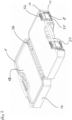
Figure 1 is a perspective view of a closed container containing a latch according to the present invention; -
Figure 2 is a perspective view of an open container containing latches according to the present invention; -
Figure 3 is a frontal view of the container and latches ofFigure 2 ; -
Figure 4 is a detailed perspective view of the container showing where a latch is connected thereto; -
Figures 5a and 5b respectively are front and rear perspective views of a latch according to the present invention; -
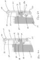
Figures 6a and 6b respectively are cutaway views of a latch in its upward and low profile positions; and -
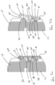
Figures 7a and 7b respectively are cutaway views of a latch in its engaged and disengaged positions. -
Figures 1 ,2 ,3 and4 depict various views of acontainer 16 andlatch 10 according to the present invention. Thelatch 10 is configured to selectively bind thelower portion 12 andupper portion 14 of thecontainer 16. The latch includes abase 18 having afront face 20, a rear face, 22, a connectedend 24, and a selectivelyengageable binding end 26. As best seen inFigure 5b , therear face 22 further includes aupward hook 28 that is adjacent the connectedend 24, adownward hook 30 that is centrally positioned on therear face 22, and abinding tooth 32 that is adjacent thebinding end 26. Theupward hook 28 and downwardhook 30 are configured to engage thelower portion 12 of thecontainer 16 and permit both axial and pivotal movement of thelatch 10. Those skilled in the art will recognize that theupward hook 28, downwardhook 30 and bindingtooth 32 may also be positioned in other places on therear face 22 without departing from the scope of the invention. - The axial movement of the
latch 10 is between an upward potion and a low profile position. In the upward position, thebinding end 26 is high enough that the binding tooth can engage and bind theupper portion 14 of thecontainer 16. In the low profile position, thebinding end 26 is too low to engage and bind theupper portion 14 of thecontainer 16. - The pivotal movement of the
latch 10 is about the connectedend 24 such that thebinding end 26 can move between a disengaged and engaged position. In the disengaged position, the binding end is distal from theupper portion 14 of thecontainer 16 such that the lower andupper portions binding end 26 is adjacent theupper portion 14 of the container such that the binding took 32 can engage theupper portion 14 of thecontainer 16 and bind the lower andupper portions - As best seen in
Figures 6a and 6b , which shows cutaway views of thelatch 10, the axial movement is facilitated by theupward hook 28 and downward hook's 30 engagement to aprotrusion 34 on thelower portion 12 of thecontainer 16. Likewise, as shown inFigures 7a and 7b , the pivotal movement of thelatch 10 is also facilitated by theupward hook 28 and downward hook's to theprotrusion 34. In a preferable embodiment, theupper hook 28 is shaped to engage anlower cavity 36 that is defined by theprotrusion 34. For example, theupper hook 28 may include arounded bulb 29 that is configured to engagelower cavity 36. Similarly, thedownward hook 30 may also be shaped to engage anupper cavity 38 defined by theprotrusion 34. For example, the downward hook may include arounded bulb 31 that is configured to engage theupper cavity 38. - In a preferable embodiment, the binding of the lower and
upper portions binding tooth 32 engaging aprotrusion 40 on theupper portion 14 of thecontainer 16. Preferably, the binding tooth engages a claspingtooth 42 that is positioned onprotrusion 40. Those skilled in the art will recognize that the claspingtooth 42 could also be replaced with a clasping depression (not shown) that is configured to receive the binding tooth. - In yet another preferable embodiment, as shown in
Figure 5b , thelatch 10 may also includevertical guides 44. Saidvertical guides 44 may be positioned on therear face 22 outside theupward hook 28 and downwardhook 30. Thevertical guides 44 are configured to guide the axial movement of the latch between its upward and low profile positions. - In addition to a standalone latch, the present invention also contemplates a container with said latch. As best seen in
Figure 2 , thecontainer 16 includes alower portion 12 and anupper portion 14 connected to one another by ahinge 46. The lower portion 122 andupper portions 14 are free to move about thehinge 46 such that when the two portions come into contact with one another, they define an interior space 48. Thelatch 10 ofcontainer 16 is configured to selectively bind the lower 12 and upper 14 portions and limit access to the interior space 48. Those skilled in the art will recognize that thelatch 10 ofcontainer 16 includes all of the elements and functionality of the stand alone latch as described above. Therefore, it is not necessary to repeat all said elements and functionality here. - We will now describe the industrial applicability of the latch and container. While on a jobsite, an operator will often need to have ongoing access to the interior space of toolbox. For example, she may be working with a variety of sockets, drill bits or accessories that are stored in an accessory toolbox. Because the job may require a variety of different tools, she may need to consistently come back to her accessory toolbox to swap out the correctly sized accessory. When working in this manner, the accessory toolbox or
container 16 is maintained in its open configuration. SeeFigure 2 . However, space on a jobsite is sometimes limited. In these situations, it may be necessary for an operator to store thecontainer 16 on a shelf or in a cubby that is out of the way. Such shelves may be height limited to allow for multiple shelves in a single confined space. To store an open accessory toolbox on a shelf such as this, it is necessary that the latch on said toolbox does not interfere with the shelves. If the latch does interfere with the shelves, it prevents the container from being fully inserted into the shelf. For example, as shown inFigure 3 , the height of the shelf may be less than h1 but greater than h2. When this happens, prior art latches that have a fixed height h1 interfere with the shelf when the container is inserted therein. To avoid this issue, the present invention discloses a container having latches that can move between an upward position (the latch on the left inFigure 3 ) and the low profile position (the latch on the right inFigure 3 ). In the upward position, thelatch 10 may be at a height h1. In the low profile position, thelatch 10 can move down to a lower height h2. When the latch is in its low profile position h2, the container can be easily stored on a shelf without the latch interfering with the same. - We will now describe the operation of the
latch 10. Acontainer 16 such as that depicted inFigure 1 is a common toolbox configured to permit the easy transport of sockets, drill bits, tools and/or other accessories. Those skilled in the art will recognize that the latch on the right has been removed to show additional details about how thelatch 10 engages thecontainer 16 and moves between its various positions e.g., upward position, low profile position, disengaged position and engaged position. As depicted inFigure 1 , thelatch 10 on the left is in its upward and engaged positions wherein it is binds theupper portion 14 of thecontainer 16, to thelower portion 12. - When an operator desires to open the
latch 10, she pulls thebinding end 26 of thelatch 10 away from the container. More specifically, she pulls thebinding end 26 away from theupper portion 14 of thecontainer 16. As best seen inFigures 7a and 7b , when the operator pulls thebinding end 26 away from theupper portion 14, the bindingtooth 32 flexes a bit to overcome the claspingtooth 42 that is positioned on theprotrusion 40. Once the bindingtooth 32 overcomes the claspingtooth 42, the latch is no longer in its engaged position. Instead, thelatch 10 is now in its disengaged position. In this position, theupper portion 14 of the container is now free to be moved away fromlower portion 12 and the interior space 48 is accessible. - Critically, when the
latch 10 is in its disengaged position, theconnected end 24 remains engaged to thelower portion 12 of the container. This engagement is achieved via theupward hook 28, thedownward hook 30 andprotrusion 34. As the latch is pivoted from the engaged position to the disengaged position, theupward hook 28 engages the bottom of theprotrusion 34, and thedownward hook 30 engages the top of theprotrusion 34. The spacing betweenupward hook 28 and thedownward hook 30 is such that when thelatch 10 is in its disengaged position, said hooks 28, 30 simultaneously engage theprotrusion 34 and secure the connected end thereto. In a preferred embodiment, theupward hook 28 may further include arounded bulb 29 that is configured to engage alower cavity 36 that is defined by theprotrusion 34. The engagement of the roundedbulb 29 into thelower cavity 36 helps further secure the latch to the protrusion. Those skilled in the art will recognize that therounded bulb 29 positioned in thelower cavity 36 also helps facilitate the pivoting movement of thelatch 10. - Once the
latch 10 has been moved from its engaged position to its disengaged position, and thecontainer 16 has been opened, the latch may be pivoted back toward the container such that the latch is in an upright or vertical position such as that shown inFigures 3 and6a . The latch on the left inFigure 3 is in its disengaged and upward position. In this position, the height of the latch as measured from the bottom of thelower portion 12 to the top or bindingend 26 of the latch may be h1. As stated above, this height may be too high to allow the entire container and latch to be stored on a shelf or in a cubby. When this occurs, as shown on the right hand side ofFigure 3 , an operator of the present invention may lower thelatch 10 such that its height is h2 (also measured from the bottom of thelower portion 12 to the top or bindingend 26 of the latch).Figures 6a and 6b show the detailed movement of thelatch 10 from its upward position (Figure 6a ) to its low profile position (Figure 6b ). InFigure 6a , theupward hook 28 is engaged to the bottom ofprotrusion 34. This engagement prevents further upward axial movement of the latch. To move thelatch 10 into its low profile position, the latch is pressed downward such that thedownward hook 30 engages theprotrusion 34. In a preferred embodiment, thelatch 10 may move from its upward position to its low profile position under the force of gravity. The one or morevertical guides 44 may guide such movement. In yet another preferred embodiment, thedownward hook 30 may further include arounded bulb 31 that is configured to engage anupper cavity 38 defined in theprotrusion 34. This engagement allows the height h2 of the low profile position to be even lower. Those skilled in the art will recognize that the space between the upward and downward hooks 28, 30 is such that no matter where thelatch 10 is in its axial spectrum (i.e., from the upward position h1 to its low profile position h2), the hooks make it difficult to remove the latch from theprotrusion 34. - When the operator is finished with her work and desires to close and secure her toolbox, she simply does all the aforementioned steps in reverse. First, she raises the latch from its low profile position to its upward position. Then she pivots the
binding end 26 of thelatch 10 away from thecontainer 16 to permit theupper portion 14 of the container to move abouthinge 46 to its closed position. Next she pivots thebinding end 26 of the latch back toward theupper portion 14. Pressure can then be applied to thebinding end 26 such that the bindingtooth 32 flexes, overcomes and becomes engaged to the clasping took 42 ofprotrusion 40. - Although aspects of the invention have been described in detail for the purpose of illustration based on what is currently considered to be the most practical and preferred embodiments, it is to be understood that such detail is solely for that purpose and that the invention is not limited to the disclosed embodiments, but, on the contrary, is intended to cover modifications and equivalent arrangements that are within the scope of the appended claims. For example, it is to be understood that the present invention contemplates that, to the extent possible, one or more features of any embodiment can be combined with one or more features of any other embodiment.
Claims (7)
- A container (16) comprising:a lower and upper portion (12, 14) connected to one another by a hinge (46) such that when the lower and upper portions (12, 14) come into contact with one another, they define an interior space (48);a latch (10) configured to selectively bind the lower and upper portions (12, 14) together and limit access to the interior space (48), said latch comprising:a base (18) having a front face (20), a rear face (22), a connected end (24), and a selectively engageable binding end (26), and wherein the rear face (22) further includes an upward hook (28) (24), a downward hook (30), and a binding tooth (32); andwherein the upward hook (28) and the downward hook (30) are configured to engage the lower portion (12) of the container (16) and permit a pivotal movement of latch (10); andwherein said pivotal movement is about the connected end such that binding end (26) can move between a disengaged and an engaged position, wherein in said disengaged position, the binding end (26) is distal from the upper portion (14) of the container (18) such that the two portions (12, 14) cannot be bound together, and in said engaged position, the binding end (26) is adjacent the upper portion (14) of the container (16) such that the binding tooth (32) can engage the upper portion (14) of the container (16) and bind the two portions (12, 14) together; andcharacterised in that the upward hook (28) and the downward hook (30) are configured to permit also an axial movement of latch (10); andwherein said axial movement is between an upward position and a low profile position, wherein in said upward position, the binding end (26) is high enough that the binding tooth (32) can engage and bind the upper portion (14) of the container (16), and in said low profile position, the binding end (26) is too low to engage and bind the upper portion (14) of the container (16).
- The container (16) of claim 1, wherein the axial and pivotal movement of the latch (10) is facilitated by the upward hook (28) and downward hook's (30) engagement to a protrusion (34) on the lower portion (12) of the container (16)
- The container (16) of claims 1 or 2, wherein the upward hook (28) is shaped to engage a lower cavity (36) defined by the protrusion (34) on the lower portion (12) of the container (16).
- The container of claims 1 to 3, wherein the downward hook (30) is shaped to engage an upper cavity (38) defined by the protrusion (34) on the lower portion (12) of the container (16).
- The container (16) of claims 1 to 4, wherein the binding together of the upper and lower portions (12, 14) of the container (16) is achieved by the binding tooth (32) engaging a protrusion (40) on the upper portion (14) of the container (16).
- The container (16) of claim 5, wherein the binding tooth (32) is shaped to engage a clasping tooth (42) positioned on the protrusion (40) on the upper portion (14) of the container (16).
- The container (16) of claims 1 to 6, wherein the rear face (22) further includes one or more vertical guides (44) that run from the connected end (24) to the binding end (26) are positioned outside of the upward hook (28), downward hook (30) and binding tooth (32).
Priority Applications (3)
| Application Number | Priority Date | Filing Date | Title |
|---|---|---|---|
| EP22182750.4A EP4302929B1 (en) | 2022-07-04 | 2022-07-04 | Container with a low profile latch |
| CN202310740811.4A CN117342111A (en) | 2022-07-04 | 2023-06-21 | low profile latch |
| US18/345,573 US12552584B2 (en) | 2022-07-04 | 2023-06-30 | Low profile latch |
Applications Claiming Priority (1)
| Application Number | Priority Date | Filing Date | Title |
|---|---|---|---|
| EP22182750.4A EP4302929B1 (en) | 2022-07-04 | 2022-07-04 | Container with a low profile latch |
Publications (2)
| Publication Number | Publication Date |
|---|---|
| EP4302929A1 EP4302929A1 (en) | 2024-01-10 |
| EP4302929B1 true EP4302929B1 (en) | 2025-04-02 |
Family
ID=82547406
Family Applications (1)
| Application Number | Title | Priority Date | Filing Date |
|---|---|---|---|
| EP22182750.4A Active EP4302929B1 (en) | 2022-07-04 | 2022-07-04 | Container with a low profile latch |
Country Status (3)
| Country | Link |
|---|---|
| US (1) | US12552584B2 (en) |
| EP (1) | EP4302929B1 (en) |
| CN (1) | CN117342111A (en) |
Families Citing this family (3)
| Publication number | Priority date | Publication date | Assignee | Title |
|---|---|---|---|---|
| MX2021000811A (en) * | 2020-01-20 | 2021-07-21 | Techtronic Cordless Gp | Stackable storage system. |
| US11738914B2 (en) | 2021-11-18 | 2023-08-29 | Yeti Coolers, Llc | Container and latching system |
| EP4302929B1 (en) * | 2022-07-04 | 2025-04-02 | Stanley Black & Decker MEA FZE | Container with a low profile latch |
Family Cites Families (121)
| Publication number | Priority date | Publication date | Assignee | Title |
|---|---|---|---|---|
| US2807387A (en) * | 1954-01-21 | 1957-09-24 | Siciliano Pasquale | Stackable containers |
| US3134617A (en) * | 1961-10-03 | 1964-05-26 | Animal Trap Co America | Latch assembly for tackle boxes and the like |
| US3174784A (en) * | 1962-10-22 | 1965-03-23 | Gunnar E Swanson | Fastening device |
| US3635361A (en) * | 1969-07-31 | 1972-01-18 | Alton Box Board Co | Handling perishable products |
| US3659743A (en) * | 1970-07-29 | 1972-05-02 | Theodor Box | Plastic nesting and stacking case |
| US4540206A (en) * | 1984-04-30 | 1985-09-10 | Southco, Inc. | Adjustable draw latch |
| US4915913A (en) * | 1984-05-22 | 1990-04-10 | Genesis Medical Corporation | Medical sterilizer device with improved latch mechanism |
| US5042674A (en) * | 1988-02-25 | 1991-08-27 | Rent A Boxx Moving Systems Inc. | Moving and storage container |
| US4893724A (en) * | 1988-06-06 | 1990-01-16 | Schiemann Dr Wolfram | Closure for a canister |
| US5199592A (en) * | 1989-03-15 | 1993-04-06 | Perstorp Extec, Inc. | Container with latchable hinged sidewall gate |
| US5011013A (en) * | 1990-04-27 | 1991-04-30 | Waterloo Industries, Inc. | Portable storage container |
| JP2585038Y2 (en) * | 1991-05-29 | 1998-11-11 | 旭光学工業株式会社 | Moving member positioning mechanism |
| US5234124A (en) * | 1992-03-13 | 1993-08-10 | American Sterilizer Company | Cassette for sterilizing articles and latch therefor |
| US5967322A (en) * | 1995-02-02 | 1999-10-19 | Rehrig Pacific Company, Inc. | Container assembly with tamper evident seal |
| US5553712A (en) * | 1995-05-05 | 1996-09-10 | Suncast Corporation | Trading card carrying and display case |
| US5730311A (en) * | 1995-11-13 | 1998-03-24 | Tenneco Packaging Inc. | Controlled atmosphere package |
| US5699925A (en) * | 1996-05-14 | 1997-12-23 | Petruzzi; Thomas G. | Interlocking stackable container storage system |
| US5860527A (en) * | 1996-10-18 | 1999-01-19 | Menasha Corporation | Plastic tote box improvements |
| US6134832A (en) * | 1999-04-27 | 2000-10-24 | Landmark Plastic Corporation | Nest and stack plant pot |
| IL135019A (en) * | 2000-03-12 | 2003-02-12 | Keter Plastic Ltd | Portable workshop container assembly |
| EP1305145B1 (en) * | 2000-08-03 | 2008-10-08 | AEG Electric Tools GmbH | Tool box |
| US7837053B2 (en) * | 2000-10-12 | 2010-11-23 | Arnett Jeffrey D | Shock-resistant and environmentally sealed container |
| US20020162841A1 (en) * | 2001-05-01 | 2002-11-07 | Amos Shamir | Single action latch |
| US20030038142A1 (en) * | 2001-08-21 | 2003-02-27 | Hyi | Storage box with improved design including replaceable hinges and latches |
| US6527309B1 (en) * | 2001-09-19 | 2003-03-04 | Hardigg Industries, Inc. | Latch apparatus |
| US6585090B2 (en) * | 2001-10-26 | 2003-07-01 | Stephen C. Harvey | Stackable interlocking carrying case for a portable computer |
| US20030111476A1 (en) * | 2001-12-19 | 2003-06-19 | Donald Serio | Air sealable container with automatically actuable pressure equalizing valve |
| GB2385091B (en) * | 2002-02-06 | 2004-05-12 | Kuo-Ping Ho | A fastening device for the backseat of a bicycle |
| US20030234200A1 (en) * | 2002-06-25 | 2003-12-25 | Asher Diamant | Stackable container |
| US6786341B2 (en) * | 2002-07-09 | 2004-09-07 | Harold K. Stinnett | Article dispensing apparatus |
| US6874634B2 (en) * | 2003-01-29 | 2005-04-05 | Riley Medical, Inc. | Variably stackable sterilization tray system |
| US6955381B2 (en) * | 2003-07-01 | 2005-10-18 | Pelican Products, Inc. | Latch mechanism for case and a carrying case with the latch |
| US20050155889A1 (en) * | 2004-01-20 | 2005-07-21 | Lown John M. | Modular and stackable tray assembly |
| ITBO20040455A1 (en) * | 2004-07-22 | 2004-10-22 | Gt Line S R L | LOCK, ESPECIALLY FOR SUITCASES, TRUNKS AND SIMILAR |
| US7658887B2 (en) * | 2004-09-02 | 2010-02-09 | Scientific Specialties, Inc. | Pipette tip grid with lock mechanism |
| US7401698B2 (en) * | 2005-02-22 | 2008-07-22 | Robert Bosch Gmbh | Latch for tool accessory case |
| US8210579B2 (en) * | 2006-03-03 | 2012-07-03 | The Stanley Works Israel Ltd. | Automatic latch and toolbox |
| EP2010434B1 (en) * | 2006-04-22 | 2013-05-22 | TANOS GmbH Verpacken Ordnen Präsentieren | Stackable boxes and covers |
| ITMI20061349A1 (en) * | 2006-07-12 | 2008-01-13 | Marco Alessandro Piacenza | STACKABLE INDEPENDENT CONTAINER SYSTEM |
| US20080116098A1 (en) * | 2006-11-16 | 2008-05-22 | Pwp Industries | Food container with breathable patch |
| US7370891B1 (en) * | 2006-11-22 | 2008-05-13 | Schmitt David A | Latching mechanism with trigger actuator |
| US8297464B2 (en) * | 2007-06-13 | 2012-10-30 | Jean-Pierre Grenier | Carrying case with locking latch mechanism |
| DE202007010828U1 (en) * | 2007-08-03 | 2008-12-18 | Zarges Gmbh | container |
| DK200800258A (en) * | 2008-02-25 | 2009-08-26 | Raaco Internat A S | Suitcase for transporting tools or the like |
| TWM351137U (en) * | 2008-04-18 | 2009-02-21 | Samson Power Tool Co Ltd | Nailing gun of nozzle quick-handling |
| US7854321B2 (en) * | 2008-07-01 | 2010-12-21 | The Stanley Works Israel Ltd. | Rolling container assembly |
| GB0816753D0 (en) * | 2008-09-12 | 2008-10-22 | Loadhog Ltd | Load securing system |
| US8851287B2 (en) * | 2009-02-27 | 2014-10-07 | Becklin Holdings, Inc. | Container stacking system with universal members |
| CA2735679C (en) * | 2009-06-29 | 2016-08-23 | Tts Tooltechnic Systems Ag & Co. Kg | Stackable container assembly with reciprocal locking of the stacked containers |
| US8240504B2 (en) * | 2009-08-20 | 2012-08-14 | Berry Plastics Corporation | Container lid with printable rim |
| US8567796B2 (en) * | 2009-09-01 | 2013-10-29 | The Stanley Works Israel Ltd. | Rolling container assembly with adjustable storage units |
| US8210387B2 (en) * | 2009-10-09 | 2012-07-03 | The Stanley Works Israel Ltd. | Organizer |
| US20110100856A1 (en) * | 2009-10-29 | 2011-05-05 | Michael Scot Rosko | Interlocking stacking container |
| USRE47022E1 (en) * | 2009-12-11 | 2018-09-04 | The Stanley Works Israel Ltd. | Container |
| US20110139777A1 (en) * | 2009-12-11 | 2011-06-16 | The Stanley Works Israel Ltd. | Container |
| US10022856B2 (en) * | 2010-01-28 | 2018-07-17 | The Stanley Works Israel Ltd. | Metal and plastic container |
| USD637001S1 (en) * | 2010-04-15 | 2011-05-03 | The Stanley Works Israel Ltd. | Toolbox top |
| US8813960B2 (en) * | 2010-08-02 | 2014-08-26 | Becklin Holdings, Inc. | Latch system for containers |
| US9469024B2 (en) * | 2010-10-04 | 2016-10-18 | The Stanley Works Israel Ltd. | Container assembly |
| US8910788B2 (en) * | 2010-11-11 | 2014-12-16 | Koninklijke Philips N.V. | Carrying case for defibrillator and accessories |
| US8950581B2 (en) * | 2010-11-30 | 2015-02-10 | Busch Systems International Inc. | Stackable container |
| US20120168444A1 (en) * | 2011-01-05 | 2012-07-05 | The Stanley Works Israel Ltd. | Container with latch |
| US20120222983A1 (en) * | 2011-03-04 | 2012-09-06 | Azad Sabounjian | Stackable containers |
| USD674605S1 (en) * | 2011-04-01 | 2013-01-22 | The Stanley Works Israel Ltd. | Storage container |
| US20120267369A1 (en) * | 2011-04-04 | 2012-10-25 | Curver Luxembourg Sarl | Storage container |
| US9199370B2 (en) * | 2011-06-17 | 2015-12-01 | Snap-On Incorporated | Latch mechanism for front opening lid |
| DE202011104615U1 (en) * | 2011-08-17 | 2011-11-10 | Innovations-Medical Gmbh | Closure for sterile containers |
| USD694522S1 (en) * | 2012-05-31 | 2013-12-03 | The Stanley Works Israel, Ltd. | Toolbox |
| EP2706177B1 (en) * | 2012-09-11 | 2015-03-18 | The Stanley Works Israel Ltd. | Storage assembly |
| CA150510S (en) * | 2012-10-17 | 2014-02-07 | Stanley Works Israel | Tool box |
| US8944476B1 (en) * | 2012-10-23 | 2015-02-03 | Royal Case Co., Inc. | Latch assemblies and transportation containers using the same |
| ES2723884T3 (en) * | 2012-12-27 | 2019-09-03 | Toolbox | |
| US9669968B2 (en) * | 2013-03-11 | 2017-06-06 | Lf Centennial Ltd. | Latch for releasably coupling elements together |
| DE202013101653U1 (en) * | 2013-04-17 | 2013-06-24 | Paul Craemer Gmbh | Transport container with marking carrier |
| EP2796248A1 (en) * | 2013-04-25 | 2014-10-29 | The Stanley Works Israel Ltd. | Toolbox lid |
| EP2815853B1 (en) * | 2013-06-20 | 2018-02-07 | The Stanley Works Israel Ltd. | Tool organiser |
| US20150001120A1 (en) * | 2013-06-27 | 2015-01-01 | John Gaskell | Storage container and system |
| US8944537B1 (en) * | 2013-10-17 | 2015-02-03 | Edwin Dizon Manalang | Drawer latch assembly a toolbox assembly |
| US9193060B2 (en) * | 2013-12-04 | 2015-11-24 | Tefenplast Ltd. | Tool box assembly |
| US20150190919A1 (en) * | 2014-01-03 | 2015-07-09 | Yuu Ching Plastics Corp. | Tool box |
| EP2965870B1 (en) * | 2014-07-09 | 2020-11-11 | The Stanley Works Israel Ltd. | Case |
| US10575417B2 (en) * | 2014-09-08 | 2020-02-25 | The Stanley Works Israel Ltd. | Jobsite communications center |
| WO2016049805A1 (en) * | 2014-09-29 | 2016-04-07 | 深圳市大疆创新科技有限公司 | Box and buckle assemblies thereof |
| EP3265391B1 (en) * | 2015-03-06 | 2022-05-04 | Keter Home and Garden Products Ltd. | Container assemblies |
| USD798053S1 (en) * | 2015-03-25 | 2017-09-26 | The Stanley Works Israel Ltd | Tool box |
| EP3138664B1 (en) * | 2015-09-04 | 2019-11-06 | The Stanley Works Israel Ltd. | Tool organiser |
| US9701443B2 (en) * | 2015-11-02 | 2017-07-11 | Compass Corporation | Set of stackable tool boxes |
| US10138032B2 (en) * | 2015-11-09 | 2018-11-27 | Chi-Hsiung Chang | Fastener assembly |
| EP3199305B1 (en) * | 2015-12-04 | 2020-04-01 | The Stanley Works Israel Ltd. | Mobile storage container with pivotable handle |
| AU2016366825B2 (en) * | 2015-12-10 | 2022-06-16 | Keter Plastic Ltd. | Container assembly |
| CN110893610A (en) * | 2016-05-02 | 2020-03-20 | 凯特尔塑料有限公司 | Utility module and coupling mechanism |
| DE102016112854A1 (en) * | 2016-07-13 | 2018-01-18 | Bs Systems Gmbh & Co. Kg | Stackable system tray |
| WO2018055575A1 (en) * | 2016-09-23 | 2018-03-29 | The Stanley Works Israel Ltd. | Toolbox with accessory tracks |
| US12108853B2 (en) * | 2019-01-06 | 2024-10-08 | Yeti Coolers, Llc | Luggage system |
| EP3638598B1 (en) * | 2017-06-12 | 2023-01-18 | Yeti Coolers, LLC | Container and latching system |
| DE102017117823A1 (en) * | 2017-08-07 | 2019-02-07 | Bs Systems Gmbh & Co. Kg | Stackable system tray |
| US10697215B2 (en) * | 2017-08-13 | 2020-06-30 | Yi-Min Li | Toolbox-locking apparatuus |
| USD851929S1 (en) * | 2017-11-01 | 2019-06-25 | The Stanley Works Israel Ltd. | Toolbox |
| USD857388S1 (en) * | 2017-11-01 | 2019-08-27 | The Stanley Works Israel Inc. | Toolbox |
| US10603783B2 (en) * | 2017-12-04 | 2020-03-31 | Black & Decker Inc. | Tool container system |
| EP3501756A1 (en) * | 2017-12-21 | 2019-06-26 | Hilti Aktiengesellschaft | Lock for a case |
| US10538365B2 (en) * | 2018-01-16 | 2020-01-21 | Cascade Mountain Technologies, Llc | Insulating device and latch |
| NL2020656B1 (en) * | 2018-03-23 | 2019-10-02 | Curtec Nederland Bv | Closure assembly for a container, combination of such a closure assembly and a container and method for closing a container |
| CH714972A1 (en) * | 2018-05-08 | 2019-11-15 | Utz Georg Holding Ag | Stackable container. |
| US11549284B2 (en) * | 2018-05-16 | 2023-01-10 | Getac Technology Corporation | Locking structure |
| US11486427B2 (en) * | 2018-07-18 | 2022-11-01 | The Stanley Works Israel Ltd. | Stacking latch mechanism |
| US11642777B2 (en) * | 2018-07-18 | 2023-05-09 | The Stanley Works Israel Ltd. | Stacking latch mechanism |
| US11472600B2 (en) * | 2018-08-20 | 2022-10-18 | GM Global Technology Operations LLC | Stackable/reconfigurable compartment bins |
| CN112805123B (en) * | 2018-09-10 | 2024-07-30 | 米沃奇电动工具公司 | Modular tool container |
| CN211483271U (en) * | 2019-11-27 | 2020-09-15 | 上海美瑞实业有限公司 | Box interlocking structure |
| US11401099B2 (en) * | 2019-12-20 | 2022-08-02 | California Innovations Inc. | Soft-sided insulated container with hard-sided liner |
| IL271995B2 (en) * | 2020-01-12 | 2023-06-01 | Keter Home & Garden Products Ltd | Utility assembly and connectivity system therefore |
| MX2021000811A (en) * | 2020-01-20 | 2021-07-21 | Techtronic Cordless Gp | Stackable storage system. |
| FR3108353B1 (en) * | 2020-03-17 | 2022-03-25 | Lisi Aerospace | Aircraft Panel Lock |
| CN111924270B (en) * | 2020-07-29 | 2022-05-20 | 上海美瑞实业有限公司 | Automatic interlocking structure, storage box and storage box assembly |
| US11472020B2 (en) * | 2021-01-15 | 2022-10-18 | Stanley Black & Decker, Inc. | Utility knife blade holder for tool container system |
| US11788329B2 (en) * | 2021-06-11 | 2023-10-17 | Ningbo E-Power Engine Technology Co., Ltd. | Latch structure |
| EP4129848B1 (en) * | 2021-08-05 | 2024-03-20 | Stanley Black & Decker MEA FZE | Container with cover having a stop block |
| US11738914B2 (en) * | 2021-11-18 | 2023-08-29 | Yeti Coolers, Llc | Container and latching system |
| US20230313580A1 (en) * | 2022-04-04 | 2023-10-05 | Lifetime Products, Inc. | Blow molded pin for hinge mechanism |
| EP4302929B1 (en) * | 2022-07-04 | 2025-04-02 | Stanley Black & Decker MEA FZE | Container with a low profile latch |
-
2022
- 2022-07-04 EP EP22182750.4A patent/EP4302929B1/en active Active
-
2023
- 2023-06-21 CN CN202310740811.4A patent/CN117342111A/en active Pending
- 2023-06-30 US US18/345,573 patent/US12552584B2/en active Active
Also Published As
| Publication number | Publication date |
|---|---|
| US20240002110A1 (en) | 2024-01-04 |
| CN117342111A (en) | 2024-01-05 |
| US12552584B2 (en) | 2026-02-17 |
| EP4302929A1 (en) | 2024-01-10 |
Similar Documents
| Publication | Publication Date | Title |
|---|---|---|
| EP4302929A1 (en) | Container and low profile latch | |
| EP1520660B1 (en) | Toolbox with handle having cover locking mechanism | |
| US9248566B2 (en) | Tool housing case and subcase | |
| EP2596920B1 (en) | Modular container assembly | |
| US6648166B2 (en) | Folding storage assembly | |
| EP2289671B1 (en) | Rolling container assembly with adjustable storage units | |
| US8157337B2 (en) | Tool box storage assembly | |
| US12605820B2 (en) | Bracket table applicable to a storage box | |
| EP2308655B1 (en) | Organizer | |
| US9850029B2 (en) | Cantilever box | |
| US9630312B2 (en) | Tool box storage assembly | |
| US9193060B2 (en) | Tool box assembly | |
| US20190210213A1 (en) | Toolbox with slidable organizer tray | |
| WO2014125484A1 (en) | Toolbox | |
| US20250198237A1 (en) | Ladder, ladder top and ladder top accessory | |
| DE202016101539U1 (en) | Vehicle storage box containing a standard connection plate connection | |
| US12343857B2 (en) | Sliding rotating storage unit | |
| US11524400B2 (en) | Work site storage lock system |
Legal Events
| Date | Code | Title | Description |
|---|---|---|---|
| PUAI | Public reference made under article 153(3) epc to a published international application that has entered the european phase |
Free format text: ORIGINAL CODE: 0009012 |
|
| STAA | Information on the status of an ep patent application or granted ep patent |
Free format text: STATUS: THE APPLICATION HAS BEEN PUBLISHED |
|
| AK | Designated contracting states |
Kind code of ref document: A1 Designated state(s): AL AT BE BG CH CY CZ DE DK EE ES FI FR GB GR HR HU IE IS IT LI LT LU LV MC MK MT NL NO PL PT RO RS SE SI SK SM TR |
|
| STAA | Information on the status of an ep patent application or granted ep patent |
Free format text: STATUS: REQUEST FOR EXAMINATION WAS MADE |
|
| 17P | Request for examination filed |
Effective date: 20240710 |
|
| RBV | Designated contracting states (corrected) |
Designated state(s): AL AT BE BG CH CY CZ DE DK EE ES FI FR GB GR HR HU IE IS IT LI LT LU LV MC MK MT NL NO PL PT RO RS SE SI SK SM TR |
|
| GRAP | Despatch of communication of intention to grant a patent |
Free format text: ORIGINAL CODE: EPIDOSNIGR1 |
|
| STAA | Information on the status of an ep patent application or granted ep patent |
Free format text: STATUS: GRANT OF PATENT IS INTENDED |
|
| RIC1 | Information provided on ipc code assigned before grant |
Ipc: B65D 45/00 20060101ALI20241219BHEP Ipc: B25H 3/02 20060101AFI20241219BHEP |
|
| INTG | Intention to grant announced |
Effective date: 20250117 |
|
| GRAS | Grant fee paid |
Free format text: ORIGINAL CODE: EPIDOSNIGR3 |
|
| GRAA | (expected) grant |
Free format text: ORIGINAL CODE: 0009210 |
|
| STAA | Information on the status of an ep patent application or granted ep patent |
Free format text: STATUS: THE PATENT HAS BEEN GRANTED |
|
| P01 | Opt-out of the competence of the unified patent court (upc) registered |
Free format text: CASE NUMBER: APP_7383/2025 Effective date: 20250213 |
|
| AK | Designated contracting states |
Kind code of ref document: B1 Designated state(s): AL AT BE BG CH CY CZ DE DK EE ES FI FR GB GR HR HU IE IS IT LI LT LU LV MC MK MT NL NO PL PT RO RS SE SI SK SM TR |
|
| REG | Reference to a national code |
Ref country code: GB Ref legal event code: FG4D |
|
| REG | Reference to a national code |
Ref country code: CH Ref legal event code: EP |
|
| REG | Reference to a national code |
Ref country code: IE Ref legal event code: FG4D |
|
| REG | Reference to a national code |
Ref country code: DE Ref legal event code: R096 Ref document number: 602022012474 Country of ref document: DE |
|
| REG | Reference to a national code |
Ref country code: NL Ref legal event code: MP Effective date: 20250402 |
|
| PG25 | Lapsed in a contracting state [announced via postgrant information from national office to epo] |
Ref country code: NL Free format text: LAPSE BECAUSE OF FAILURE TO SUBMIT A TRANSLATION OF THE DESCRIPTION OR TO PAY THE FEE WITHIN THE PRESCRIBED TIME-LIMIT Effective date: 20250402 |
|
| REG | Reference to a national code |
Ref country code: AT Ref legal event code: MK05 Ref document number: 1780848 Country of ref document: AT Kind code of ref document: T Effective date: 20250402 |
|
| PG25 | Lapsed in a contracting state [announced via postgrant information from national office to epo] |
Ref country code: FI Free format text: LAPSE BECAUSE OF FAILURE TO SUBMIT A TRANSLATION OF THE DESCRIPTION OR TO PAY THE FEE WITHIN THE PRESCRIBED TIME-LIMIT Effective date: 20250402 Ref country code: ES Free format text: LAPSE BECAUSE OF FAILURE TO SUBMIT A TRANSLATION OF THE DESCRIPTION OR TO PAY THE FEE WITHIN THE PRESCRIBED TIME-LIMIT Effective date: 20250402 Ref country code: PT Free format text: LAPSE BECAUSE OF FAILURE TO SUBMIT A TRANSLATION OF THE DESCRIPTION OR TO PAY THE FEE WITHIN THE PRESCRIBED TIME-LIMIT Effective date: 20250804 |
|
| PGFP | Annual fee paid to national office [announced via postgrant information from national office to epo] |
Ref country code: DE Payment date: 20250722 Year of fee payment: 4 |
|
| REG | Reference to a national code |
Ref country code: LT Ref legal event code: MG9D |
|
| PG25 | Lapsed in a contracting state [announced via postgrant information from national office to epo] |
Ref country code: GR Free format text: LAPSE BECAUSE OF FAILURE TO SUBMIT A TRANSLATION OF THE DESCRIPTION OR TO PAY THE FEE WITHIN THE PRESCRIBED TIME-LIMIT Effective date: 20250703 Ref country code: NO Free format text: LAPSE BECAUSE OF FAILURE TO SUBMIT A TRANSLATION OF THE DESCRIPTION OR TO PAY THE FEE WITHIN THE PRESCRIBED TIME-LIMIT Effective date: 20250702 |
|
| PG25 | Lapsed in a contracting state [announced via postgrant information from national office to epo] |
Ref country code: PL Free format text: LAPSE BECAUSE OF FAILURE TO SUBMIT A TRANSLATION OF THE DESCRIPTION OR TO PAY THE FEE WITHIN THE PRESCRIBED TIME-LIMIT Effective date: 20250402 |
|
| PG25 | Lapsed in a contracting state [announced via postgrant information from national office to epo] |
Ref country code: BG Free format text: LAPSE BECAUSE OF FAILURE TO SUBMIT A TRANSLATION OF THE DESCRIPTION OR TO PAY THE FEE WITHIN THE PRESCRIBED TIME-LIMIT Effective date: 20250402 |
|
| PG25 | Lapsed in a contracting state [announced via postgrant information from national office to epo] |
Ref country code: HR Free format text: LAPSE BECAUSE OF FAILURE TO SUBMIT A TRANSLATION OF THE DESCRIPTION OR TO PAY THE FEE WITHIN THE PRESCRIBED TIME-LIMIT Effective date: 20250402 |
|
| PG25 | Lapsed in a contracting state [announced via postgrant information from national office to epo] |
Ref country code: AT Free format text: LAPSE BECAUSE OF FAILURE TO SUBMIT A TRANSLATION OF THE DESCRIPTION OR TO PAY THE FEE WITHIN THE PRESCRIBED TIME-LIMIT Effective date: 20250402 |
|
| PG25 | Lapsed in a contracting state [announced via postgrant information from national office to epo] |
Ref country code: RS Free format text: LAPSE BECAUSE OF FAILURE TO SUBMIT A TRANSLATION OF THE DESCRIPTION OR TO PAY THE FEE WITHIN THE PRESCRIBED TIME-LIMIT Effective date: 20250702 |
|
| PG25 | Lapsed in a contracting state [announced via postgrant information from national office to epo] |
Ref country code: IS Free format text: LAPSE BECAUSE OF FAILURE TO SUBMIT A TRANSLATION OF THE DESCRIPTION OR TO PAY THE FEE WITHIN THE PRESCRIBED TIME-LIMIT Effective date: 20250802 |
|
| PG25 | Lapsed in a contracting state [announced via postgrant information from national office to epo] |
Ref country code: LV Free format text: LAPSE BECAUSE OF FAILURE TO SUBMIT A TRANSLATION OF THE DESCRIPTION OR TO PAY THE FEE WITHIN THE PRESCRIBED TIME-LIMIT Effective date: 20250402 |
|
| REG | Reference to a national code |
Ref country code: DE Ref legal event code: R097 Ref document number: 602022012474 Country of ref document: DE |
|
| PG25 | Lapsed in a contracting state [announced via postgrant information from national office to epo] |
Ref country code: SM Free format text: LAPSE BECAUSE OF FAILURE TO SUBMIT A TRANSLATION OF THE DESCRIPTION OR TO PAY THE FEE WITHIN THE PRESCRIBED TIME-LIMIT Effective date: 20250402 Ref country code: DK Free format text: LAPSE BECAUSE OF FAILURE TO SUBMIT A TRANSLATION OF THE DESCRIPTION OR TO PAY THE FEE WITHIN THE PRESCRIBED TIME-LIMIT Effective date: 20250402 |
|
| PG25 | Lapsed in a contracting state [announced via postgrant information from national office to epo] |
Ref country code: CZ Free format text: LAPSE BECAUSE OF FAILURE TO SUBMIT A TRANSLATION OF THE DESCRIPTION OR TO PAY THE FEE WITHIN THE PRESCRIBED TIME-LIMIT Effective date: 20250402 |
|
| PG25 | Lapsed in a contracting state [announced via postgrant information from national office to epo] |
Ref country code: EE Free format text: LAPSE BECAUSE OF FAILURE TO SUBMIT A TRANSLATION OF THE DESCRIPTION OR TO PAY THE FEE WITHIN THE PRESCRIBED TIME-LIMIT Effective date: 20250402 |
|
| PG25 | Lapsed in a contracting state [announced via postgrant information from national office to epo] |
Ref country code: SK Free format text: LAPSE BECAUSE OF FAILURE TO SUBMIT A TRANSLATION OF THE DESCRIPTION OR TO PAY THE FEE WITHIN THE PRESCRIBED TIME-LIMIT Effective date: 20250402 |
|
| PG25 | Lapsed in a contracting state [announced via postgrant information from national office to epo] |
Ref country code: IT Free format text: LAPSE BECAUSE OF FAILURE TO SUBMIT A TRANSLATION OF THE DESCRIPTION OR TO PAY THE FEE WITHIN THE PRESCRIBED TIME-LIMIT Effective date: 20250402 |
|
| PLBE | No opposition filed within time limit |
Free format text: ORIGINAL CODE: 0009261 |
|
| STAA | Information on the status of an ep patent application or granted ep patent |
Free format text: STATUS: NO OPPOSITION FILED WITHIN TIME LIMIT |
|
| REG | Reference to a national code |
Ref country code: CH Ref legal event code: L10 Free format text: ST27 STATUS EVENT CODE: U-0-0-L10-L00 (AS PROVIDED BY THE NATIONAL OFFICE) Effective date: 20260211 |
|
| REG | Reference to a national code |
Ref country code: CH Ref legal event code: H13 Free format text: ST27 STATUS EVENT CODE: U-0-0-H10-H13 (AS PROVIDED BY THE NATIONAL OFFICE) Effective date: 20260224 |
|
| PG25 | Lapsed in a contracting state [announced via postgrant information from national office to epo] |
Ref country code: RO Free format text: LAPSE BECAUSE OF FAILURE TO SUBMIT A TRANSLATION OF THE DESCRIPTION OR TO PAY THE FEE WITHIN THE PRESCRIBED TIME-LIMIT Effective date: 20250402 |
|
| 26N | No opposition filed |
Effective date: 20260105 |
|
| PG25 | Lapsed in a contracting state [announced via postgrant information from national office to epo] |
Ref country code: LU Free format text: LAPSE BECAUSE OF NON-PAYMENT OF DUE FEES Effective date: 20250704 |
|
| REG | Reference to a national code |
Ref country code: BE Ref legal event code: MM Effective date: 20250731 |
|
| PG25 | Lapsed in a contracting state [announced via postgrant information from national office to epo] |
Ref country code: BE Free format text: LAPSE BECAUSE OF NON-PAYMENT OF DUE FEES Effective date: 20250731 |
|
| PG25 | Lapsed in a contracting state [announced via postgrant information from national office to epo] |
Ref country code: FR Free format text: LAPSE BECAUSE OF NON-PAYMENT OF DUE FEES Effective date: 20250731 |
|
| PG25 | Lapsed in a contracting state [announced via postgrant information from national office to epo] |
Ref country code: CH Free format text: LAPSE BECAUSE OF NON-PAYMENT OF DUE FEES Effective date: 20250731 |