EP4302628A1 - Sockliner and method of manufacturing the same - Google Patents
Sockliner and method of manufacturing the same Download PDFInfo
- Publication number
- EP4302628A1 EP4302628A1 EP23182041.6A EP23182041A EP4302628A1 EP 4302628 A1 EP4302628 A1 EP 4302628A1 EP 23182041 A EP23182041 A EP 23182041A EP 4302628 A1 EP4302628 A1 EP 4302628A1
- Authority
- EP
- European Patent Office
- Prior art keywords
- layer portion
- sockliner
- upper layer
- holes
- base layer
- Prior art date
- Legal status (The legal status is an assumption and is not a legal conclusion. Google has not performed a legal analysis and makes no representation as to the accuracy of the status listed.)
- Pending
Links
- 238000004519 manufacturing process Methods 0.000 title claims description 112
- 230000002093 peripheral effect Effects 0.000 claims abstract description 62
- 210000002683 foot Anatomy 0.000 claims description 88
- 239000000654 additive Substances 0.000 claims description 55
- 230000000996 additive effect Effects 0.000 claims description 55
- 238000006116 polymerization reaction Methods 0.000 claims description 23
- 210000004744 fore-foot Anatomy 0.000 claims description 22
- 238000000034 method Methods 0.000 claims description 21
- 210000000452 mid-foot Anatomy 0.000 claims description 11
- 239000011159 matrix material Substances 0.000 claims description 9
- 230000000149 penetrating effect Effects 0.000 claims description 5
- 238000003491 array Methods 0.000 claims description 4
- 239000004745 nonwoven fabric Substances 0.000 claims description 4
- 239000002759 woven fabric Substances 0.000 claims description 4
- 239000010410 layer Substances 0.000 description 267
- 229920005989 resin Polymers 0.000 description 26
- 239000011347 resin Substances 0.000 description 26
- 230000004048 modification Effects 0.000 description 25
- 238000012986 modification Methods 0.000 description 25
- 229920000642 polymer Polymers 0.000 description 25
- 229920001577 copolymer Polymers 0.000 description 21
- 238000010586 diagram Methods 0.000 description 21
- 239000007788 liquid Substances 0.000 description 21
- 239000004744 fabric Substances 0.000 description 19
- 238000013507 mapping Methods 0.000 description 15
- 239000012790 adhesive layer Substances 0.000 description 11
- 229920001971 elastomer Polymers 0.000 description 11
- PPBRXRYQALVLMV-UHFFFAOYSA-N Styrene Chemical compound C=CC1=CC=CC=C1 PPBRXRYQALVLMV-UHFFFAOYSA-N 0.000 description 10
- 238000009826 distribution Methods 0.000 description 10
- 230000035939 shock Effects 0.000 description 10
- 239000000463 material Substances 0.000 description 9
- 230000035699 permeability Effects 0.000 description 9
- -1 TPAE) Polymers 0.000 description 7
- 229920000058 polyacrylate Polymers 0.000 description 7
- JOYRKODLDBILNP-UHFFFAOYSA-N Ethyl urethane Chemical compound CCOC(N)=O JOYRKODLDBILNP-UHFFFAOYSA-N 0.000 description 6
- 239000000806 elastomer Substances 0.000 description 6
- 125000005395 methacrylic acid group Chemical group 0.000 description 6
- 229920000728 polyester Polymers 0.000 description 6
- 239000005060 rubber Substances 0.000 description 6
- 239000000853 adhesive Substances 0.000 description 5
- UHESRSKEBRADOO-UHFFFAOYSA-N ethyl carbamate;prop-2-enoic acid Chemical compound OC(=O)C=C.CCOC(N)=O UHESRSKEBRADOO-UHFFFAOYSA-N 0.000 description 5
- 230000007246 mechanism Effects 0.000 description 5
- 239000004721 Polyphenylene oxide Substances 0.000 description 4
- 230000009471 action Effects 0.000 description 4
- 150000001408 amides Chemical class 0.000 description 4
- 238000013461 design Methods 0.000 description 4
- 150000002148 esters Chemical class 0.000 description 4
- 229920000570 polyether Polymers 0.000 description 4
- 239000002994 raw material Substances 0.000 description 4
- 239000005062 Polybutadiene Substances 0.000 description 3
- 239000005038 ethylene vinyl acetate Substances 0.000 description 3
- 229920001200 poly(ethylene-vinyl acetate) Polymers 0.000 description 3
- 229920002857 polybutadiene Polymers 0.000 description 3
- 239000004417 polycarbonate Substances 0.000 description 3
- 229920000515 polycarbonate Polymers 0.000 description 3
- 238000003860 storage Methods 0.000 description 3
- 229920000468 styrene butadiene styrene block copolymer Polymers 0.000 description 3
- 229920002725 thermoplastic elastomer Polymers 0.000 description 3
- 229920002803 thermoplastic polyurethane Polymers 0.000 description 3
- 239000004593 Epoxy Substances 0.000 description 2
- 244000043261 Hevea brasiliensis Species 0.000 description 2
- 229920000459 Nitrile rubber Polymers 0.000 description 2
- 239000004433 Thermoplastic polyurethane Substances 0.000 description 2
- XECAHXYUAAWDEL-UHFFFAOYSA-N acrylonitrile butadiene styrene Chemical compound C=CC=C.C=CC#N.C=CC1=CC=CC=C1 XECAHXYUAAWDEL-UHFFFAOYSA-N 0.000 description 2
- 239000004676 acrylonitrile butadiene styrene Substances 0.000 description 2
- 229920000122 acrylonitrile butadiene styrene Polymers 0.000 description 2
- 230000002411 adverse Effects 0.000 description 2
- 229920005549 butyl rubber Polymers 0.000 description 2
- 238000004891 communication Methods 0.000 description 2
- 230000007547 defect Effects 0.000 description 2
- 150000001993 dienes Chemical class 0.000 description 2
- 239000000835 fiber Substances 0.000 description 2
- 229920001903 high density polyethylene Polymers 0.000 description 2
- 239000004700 high-density polyethylene Substances 0.000 description 2
- 238000003384 imaging method Methods 0.000 description 2
- 230000006872 improvement Effects 0.000 description 2
- 229920003049 isoprene rubber Polymers 0.000 description 2
- 239000000203 mixture Substances 0.000 description 2
- 229920003052 natural elastomer Polymers 0.000 description 2
- 229920001194 natural rubber Polymers 0.000 description 2
- 230000000737 periodic effect Effects 0.000 description 2
- 229920001084 poly(chloroprene) Polymers 0.000 description 2
- 229920002635 polyurethane Polymers 0.000 description 2
- 239000004814 polyurethane Substances 0.000 description 2
- 238000005406 washing Methods 0.000 description 2
- 239000004925 Acrylic resin Substances 0.000 description 1
- 229920000178 Acrylic resin Polymers 0.000 description 1
- PKHKSCDFQWKYKA-UHFFFAOYSA-N C=CC1=CC=CC=C1.C=CC=C.C=CC1=CC=CC=C1.C=CC=C.C=CC1=CC=CC=C1 Chemical compound C=CC1=CC=CC=C1.C=CC=C.C=CC1=CC=CC=C1.C=CC=C.C=CC1=CC=CC=C1 PKHKSCDFQWKYKA-UHFFFAOYSA-N 0.000 description 1
- 229920000742 Cotton Polymers 0.000 description 1
- 229920010126 Linear Low Density Polyethylene (LLDPE) Polymers 0.000 description 1
- 229920000571 Nylon 11 Polymers 0.000 description 1
- 229920000299 Nylon 12 Polymers 0.000 description 1
- 229920002292 Nylon 6 Polymers 0.000 description 1
- 229920000305 Nylon 6,10 Polymers 0.000 description 1
- 229920002302 Nylon 6,6 Polymers 0.000 description 1
- 239000004698 Polyethylene Substances 0.000 description 1
- 239000004793 Polystyrene Substances 0.000 description 1
- 229920001893 acrylonitrile styrene Polymers 0.000 description 1
- 230000000903 blocking effect Effects 0.000 description 1
- BDGJRWFEEJVDBX-UHFFFAOYSA-N but-1-ene;4-methylpent-1-ene Chemical compound CCC=C.CC(C)CC=C BDGJRWFEEJVDBX-UHFFFAOYSA-N 0.000 description 1
- UREWAKSZTRITCZ-UHFFFAOYSA-N buta-1,3-diene;styrene Chemical compound C=CC=C.C=CC=C.C=CC1=CC=CC=C1.C=CC1=CC=CC=C1 UREWAKSZTRITCZ-UHFFFAOYSA-N 0.000 description 1
- FACXGONDLDSNOE-UHFFFAOYSA-N buta-1,3-diene;styrene Chemical compound C=CC=C.C=CC1=CC=CC=C1.C=CC1=CC=CC=C1 FACXGONDLDSNOE-UHFFFAOYSA-N 0.000 description 1
- QYMGIIIPAFAFRX-UHFFFAOYSA-N butyl prop-2-enoate;ethene Chemical compound C=C.CCCCOC(=O)C=C QYMGIIIPAFAFRX-UHFFFAOYSA-N 0.000 description 1
- 239000003795 chemical substances by application Substances 0.000 description 1
- 229910003460 diamond Inorganic materials 0.000 description 1
- 239000010432 diamond Substances 0.000 description 1
- 230000000694 effects Effects 0.000 description 1
- 229920005648 ethylene methacrylic acid copolymer Polymers 0.000 description 1
- 229920006245 ethylene-butyl acrylate Polymers 0.000 description 1
- 229920006244 ethylene-ethyl acrylate Polymers 0.000 description 1
- 229920006225 ethylene-methyl acrylate Polymers 0.000 description 1
- 229920005680 ethylene-methyl methacrylate copolymer Polymers 0.000 description 1
- 239000003292 glue Substances 0.000 description 1
- 230000017525 heat dissipation Effects 0.000 description 1
- 238000010438 heat treatment Methods 0.000 description 1
- 238000001746 injection moulding Methods 0.000 description 1
- 229920003145 methacrylic acid copolymer Polymers 0.000 description 1
- 229940117841 methacrylic acid copolymer Drugs 0.000 description 1
- 238000000465 moulding Methods 0.000 description 1
- 229920001778 nylon Polymers 0.000 description 1
- 229920006285 olefinic elastomer Polymers 0.000 description 1
- 229920003229 poly(methyl methacrylate) Polymers 0.000 description 1
- 229920002647 polyamide Polymers 0.000 description 1
- 229920001707 polybutylene terephthalate Polymers 0.000 description 1
- 229920000573 polyethylene Polymers 0.000 description 1
- 229920000139 polyethylene terephthalate Polymers 0.000 description 1
- 239000005020 polyethylene terephthalate Substances 0.000 description 1
- 239000004926 polymethyl methacrylate Substances 0.000 description 1
- 229920000098 polyolefin Polymers 0.000 description 1
- 229920005672 polyolefin resin Polymers 0.000 description 1
- 229920001296 polysiloxane Polymers 0.000 description 1
- 229920002223 polystyrene Polymers 0.000 description 1
- 239000004800 polyvinyl chloride Substances 0.000 description 1
- 229920000915 polyvinyl chloride Polymers 0.000 description 1
- SCUZVMOVTVSBLE-UHFFFAOYSA-N prop-2-enenitrile;styrene Chemical compound C=CC#N.C=CC1=CC=CC=C1 SCUZVMOVTVSBLE-UHFFFAOYSA-N 0.000 description 1
- 230000009467 reduction Effects 0.000 description 1
- 229920002050 silicone resin Polymers 0.000 description 1
- 229920002379 silicone rubber Polymers 0.000 description 1
- 229920003048 styrene butadiene rubber Polymers 0.000 description 1
- 229920002994 synthetic fiber Polymers 0.000 description 1
- 239000012209 synthetic fiber Substances 0.000 description 1
- 238000012549 training Methods 0.000 description 1
- 239000002699 waste material Substances 0.000 description 1
Images


Classifications
-
- A—HUMAN NECESSITIES
- A43—FOOTWEAR
- A43B—CHARACTERISTIC FEATURES OF FOOTWEAR; PARTS OF FOOTWEAR
- A43B17/00—Insoles for insertion, e.g. footbeds or inlays, for attachment to the shoe after the upper has been joined
- A43B17/003—Insoles for insertion, e.g. footbeds or inlays, for attachment to the shoe after the upper has been joined characterised by the material
- A43B17/006—Insoles for insertion, e.g. footbeds or inlays, for attachment to the shoe after the upper has been joined characterised by the material multilayered
-
- A—HUMAN NECESSITIES
- A43—FOOTWEAR
- A43B—CHARACTERISTIC FEATURES OF FOOTWEAR; PARTS OF FOOTWEAR
- A43B17/00—Insoles for insertion, e.g. footbeds or inlays, for attachment to the shoe after the upper has been joined
- A43B17/08—Insoles for insertion, e.g. footbeds or inlays, for attachment to the shoe after the upper has been joined ventilated
-
- A—HUMAN NECESSITIES
- A43—FOOTWEAR
- A43B—CHARACTERISTIC FEATURES OF FOOTWEAR; PARTS OF FOOTWEAR
- A43B7/00—Footwear with health or hygienic arrangements
- A43B7/14—Footwear with health or hygienic arrangements with foot-supporting parts
- A43B7/1405—Footwear with health or hygienic arrangements with foot-supporting parts with pads or holes on one or more locations, or having an anatomical or curved form
- A43B7/141—Footwear with health or hygienic arrangements with foot-supporting parts with pads or holes on one or more locations, or having an anatomical or curved form having an anatomical or curved form
-
- A—HUMAN NECESSITIES
- A43—FOOTWEAR
- A43B—CHARACTERISTIC FEATURES OF FOOTWEAR; PARTS OF FOOTWEAR
- A43B17/00—Insoles for insertion, e.g. footbeds or inlays, for attachment to the shoe after the upper has been joined
- A43B17/02—Insoles for insertion, e.g. footbeds or inlays, for attachment to the shoe after the upper has been joined wedge-like or resilient
-
- A—HUMAN NECESSITIES
- A43—FOOTWEAR
- A43B—CHARACTERISTIC FEATURES OF FOOTWEAR; PARTS OF FOOTWEAR
- A43B17/00—Insoles for insertion, e.g. footbeds or inlays, for attachment to the shoe after the upper has been joined
- A43B17/14—Insoles for insertion, e.g. footbeds or inlays, for attachment to the shoe after the upper has been joined made of sponge, rubber, or plastic materials
-
- A—HUMAN NECESSITIES
- A43—FOOTWEAR
- A43B—CHARACTERISTIC FEATURES OF FOOTWEAR; PARTS OF FOOTWEAR
- A43B7/00—Footwear with health or hygienic arrangements
- A43B7/14—Footwear with health or hygienic arrangements with foot-supporting parts
- A43B7/1405—Footwear with health or hygienic arrangements with foot-supporting parts with pads or holes on one or more locations, or having an anatomical or curved form
- A43B7/1415—Footwear with health or hygienic arrangements with foot-supporting parts with pads or holes on one or more locations, or having an anatomical or curved form characterised by the location under the foot
- A43B7/142—Footwear with health or hygienic arrangements with foot-supporting parts with pads or holes on one or more locations, or having an anatomical or curved form characterised by the location under the foot situated under the medial arch, i.e. under the navicular or cuneiform bones
-
- A—HUMAN NECESSITIES
- A43—FOOTWEAR
- A43B—CHARACTERISTIC FEATURES OF FOOTWEAR; PARTS OF FOOTWEAR
- A43B7/00—Footwear with health or hygienic arrangements
- A43B7/14—Footwear with health or hygienic arrangements with foot-supporting parts
- A43B7/1405—Footwear with health or hygienic arrangements with foot-supporting parts with pads or holes on one or more locations, or having an anatomical or curved form
- A43B7/1415—Footwear with health or hygienic arrangements with foot-supporting parts with pads or holes on one or more locations, or having an anatomical or curved form characterised by the location under the foot
- A43B7/144—Footwear with health or hygienic arrangements with foot-supporting parts with pads or holes on one or more locations, or having an anatomical or curved form characterised by the location under the foot situated under the heel, i.e. the calcaneus bone
-
- A—HUMAN NECESSITIES
- A43—FOOTWEAR
- A43B—CHARACTERISTIC FEATURES OF FOOTWEAR; PARTS OF FOOTWEAR
- A43B7/00—Footwear with health or hygienic arrangements
- A43B7/14—Footwear with health or hygienic arrangements with foot-supporting parts
- A43B7/1405—Footwear with health or hygienic arrangements with foot-supporting parts with pads or holes on one or more locations, or having an anatomical or curved form
- A43B7/1415—Footwear with health or hygienic arrangements with foot-supporting parts with pads or holes on one or more locations, or having an anatomical or curved form characterised by the location under the foot
- A43B7/145—Footwear with health or hygienic arrangements with foot-supporting parts with pads or holes on one or more locations, or having an anatomical or curved form characterised by the location under the foot situated under the toes, i.e. the phalanges
-
- A—HUMAN NECESSITIES
- A43—FOOTWEAR
- A43B—CHARACTERISTIC FEATURES OF FOOTWEAR; PARTS OF FOOTWEAR
- A43B7/00—Footwear with health or hygienic arrangements
- A43B7/14—Footwear with health or hygienic arrangements with foot-supporting parts
- A43B7/1405—Footwear with health or hygienic arrangements with foot-supporting parts with pads or holes on one or more locations, or having an anatomical or curved form
- A43B7/1475—Footwear with health or hygienic arrangements with foot-supporting parts with pads or holes on one or more locations, or having an anatomical or curved form characterised by the type of support
- A43B7/149—Pads, e.g. protruding on the foot-facing surface
-
- A—HUMAN NECESSITIES
- A43—FOOTWEAR
- A43B—CHARACTERISTIC FEATURES OF FOOTWEAR; PARTS OF FOOTWEAR
- A43B7/00—Footwear with health or hygienic arrangements
- A43B7/14—Footwear with health or hygienic arrangements with foot-supporting parts
- A43B7/28—Adapting the inner sole or the side of the upper of the shoe to the sole of the foot
-
- A—HUMAN NECESSITIES
- A43—FOOTWEAR
- A43D—MACHINES, TOOLS, EQUIPMENT OR METHODS FOR MANUFACTURING OR REPAIRING FOOTWEAR
- A43D8/00—Machines for cutting, ornamenting, marking or otherwise working up shoe part blanks
-
- B—PERFORMING OPERATIONS; TRANSPORTING
- B29—WORKING OF PLASTICS; WORKING OF SUBSTANCES IN A PLASTIC STATE IN GENERAL
- B29D—PRODUCING PARTICULAR ARTICLES FROM PLASTICS OR FROM SUBSTANCES IN A PLASTIC STATE
- B29D35/00—Producing footwear
- B29D35/12—Producing parts thereof, e.g. soles, heels, uppers, by a moulding technique
- B29D35/122—Soles
-
- B—PERFORMING OPERATIONS; TRANSPORTING
- B33—ADDITIVE MANUFACTURING TECHNOLOGY
- B33Y—ADDITIVE MANUFACTURING, i.e. MANUFACTURING OF THREE-DIMENSIONAL [3-D] OBJECTS BY ADDITIVE DEPOSITION, ADDITIVE AGGLOMERATION OR ADDITIVE LAYERING, e.g. BY 3-D PRINTING, STEREOLITHOGRAPHY OR SELECTIVE LASER SINTERING
- B33Y10/00—Processes of additive manufacturing
-
- B—PERFORMING OPERATIONS; TRANSPORTING
- B33—ADDITIVE MANUFACTURING TECHNOLOGY
- B33Y—ADDITIVE MANUFACTURING, i.e. MANUFACTURING OF THREE-DIMENSIONAL [3-D] OBJECTS BY ADDITIVE DEPOSITION, ADDITIVE AGGLOMERATION OR ADDITIVE LAYERING, e.g. BY 3-D PRINTING, STEREOLITHOGRAPHY OR SELECTIVE LASER SINTERING
- B33Y80/00—Products made by additive manufacturing
-
- B—PERFORMING OPERATIONS; TRANSPORTING
- B29—WORKING OF PLASTICS; WORKING OF SUBSTANCES IN A PLASTIC STATE IN GENERAL
- B29C—SHAPING OR JOINING OF PLASTICS; SHAPING OF MATERIAL IN A PLASTIC STATE, NOT OTHERWISE PROVIDED FOR; AFTER-TREATMENT OF THE SHAPED PRODUCTS, e.g. REPAIRING
- B29C64/00—Additive manufacturing, i.e. manufacturing of three-dimensional [3D] objects by additive deposition, additive agglomeration or additive layering, e.g. by 3D printing, stereolithography or selective laser sintering
- B29C64/10—Processes of additive manufacturing
- B29C64/106—Processes of additive manufacturing using only liquids or viscous materials, e.g. depositing a continuous bead of viscous material
- B29C64/124—Processes of additive manufacturing using only liquids or viscous materials, e.g. depositing a continuous bead of viscous material using layers of liquid which are selectively solidified
- B29C64/129—Processes of additive manufacturing using only liquids or viscous materials, e.g. depositing a continuous bead of viscous material using layers of liquid which are selectively solidified characterised by the energy source therefor, e.g. by global irradiation combined with a mask
- B29C64/135—Processes of additive manufacturing using only liquids or viscous materials, e.g. depositing a continuous bead of viscous material using layers of liquid which are selectively solidified characterised by the energy source therefor, e.g. by global irradiation combined with a mask the energy source being concentrated, e.g. scanning lasers or focused light sources
Definitions
- the present disclosure relates to a sockliner and a method of manufacturing the sockliner.
- U.S. Patent Application Publication No. 2018/228401 discloses a sockliner manufactured by a three-dimensional additive manufacturing method.
- the sockliner is manufactured in the following manner. Specifically, the foot pressure of a foot of a user who stands upright is first measured at each site on the foot sole of the user. Then, a cell corresponding to the measured foot pressure is selected from a plurality of cells each formed of a three-dimensional lattice structure or the like prepared in advance, and then mapped to each site on the corresponding position on the foot sole, to thereby generate three-dimensional mesh data of the sockliner, and then additively manufacture a sockliner based on the generated three-dimensional mesh data by a three-dimensional additive manufacturing method.
- the sockliner disclosed in the above-mentioned publication is manufactured according to the above-mentioned manufacturing method, with the result that not only a large number of holes are present inside the sockliner but also a large number of holes are exposed to the outside over the entire outer surface of the sockliner. Although such a large number of holes contribute to improvement in performance of the sockliner such as improvement in shock absorbing performance and reduction in weight, these holes may adversely affect the wearing comfort of the user if no measures are taken.
- peripheral edge of the sockliner in a plan view of the upper surface is also continuously rubbed against the footwear worn by the user.
- a large number of holes provided to reach the peripheral edge tend to cause damage to the sockliner starting from this peripheral edge, which may lead to a problem of poor durability.
- an object of the present disclosure is to provide a sockliner achieving high performance, an excellent feel of contact for a foot, and excellent durability, and a method of manufacturing the sockliner.
- a sockliner includes: a forefoot portion that supports a toe portion and a ball portion of a foot of a user; a midfoot portion that supports an arch portion of the foot of the user; and a rearfoot portion that supports a heel portion of the foot of the user.
- the sockliner is also dispose on an inner bottom surface of footwear for use.
- the sockliner includes: a base layer portion disposed with a lower surface facing the inner bottom surface of the footwear; and an upper layer portion configured to cover an upper surface of the base layer portion.
- the base layer portion includes a three-dimensional mesh structure body in which a unit structure is repeatedly arranged in multiple arrays, the unit structure having at least one of a three-dimensional lattice structure and a three-dimensional wall structure.
- the upper layer portion is formed of a sheet-like structure body including a through-hole group including a plurality of holes penetrating through the upper layer portion in a thickness direction of the upper layer portion. Each of the holes included in the through-hole group is located inward from a peripheral edge of the upper layer portion without reaching the peripheral edge of the upper layer portion.
- the through-hole group includes an outermost hole group including a plurality of holes located closest to the peripheral edge of the upper layer portion so as to overlap with the surrounding region and to align along the peripheral edge of the upper layer portion.
- a method of manufacturing a sockliner according to a first aspect of the present disclosure is a method for manufacturing the sockliner according to the present disclosure, in which the base layer portion and the upper layer portion are formed of a single component, and the base layer portion and the upper layer portion that are formed of a single component are formed of a single additively manufactured product produced by a vat polymerization three-dimensional additive manufacturing method.
- the method includes: producing the base layer portion; and producing the upper layer portion.
- the base layer portion and the upper layer portion are simultaneously and sequentially accumulated from a rear end area of the rearfoot portion to a front end area of the forefoot portion by additive manufacturing.
- a method of manufacturing a sockliner according to a second aspect of the present disclosure is a method for manufacturing the sockliner according to the present disclosure, in which the base layer portion and the upper layer portion are formed of a single component, and the base layer portion and the upper layer portion that are formed of a single component are formed of a single additively manufactured product produced by a vat polymerization three-dimensional additive manufacturing method.
- the method includes: producing the base layer portion; and producing the upper layer portion.
- the method of manufacturing a sockliner in the producing of the base layer portion and the producing of the upper layer portion, by a vat polymerization three-dimensional additive manufacturing method, at least a part of the base layer portion is simultaneously and sequentially accumulated from a side of the lower surface of the base layer portion in a direction orthogonal to the lower surface of the base layer portion, and subsequently, at least a part of the upper layer portion is simultaneously and sequentially accumulated by additive manufacturing.
- Fig. 1 is a schematic diagram for illustrating a use mode of a sockliner according to the first embodiment
- Figs. 2 and 3 are perspective views of the sockliner shown in Fig. 1 as viewed from the obliquely upper right front side and the obliquely lower left rear side, respectively.
- Fig. 4 is a plan view of the sockliner shown in Fig. 1
- Fig. 5 is a side view of the sockliner shown in Fig. 1 as viewed from the lateral foot side.
- Fig. 6 is a partially cutaway perspective view of the sockliner shown in Fig. 1 taken along a line VI-VI shown in Figs. 2 , 4 , and 5 .
- Figs. 1 to 6 a schematic configuration of a sockliner 1A according to the present embodiment will be first described.
- the sockliner 1A is placed for use, for example, on a shoe 100 as footwear.
- the shoe 100 includes a sole 110 and an upper 120.
- the sockliner 1A is inserted into the shoe 100 through a topline 121 provided in the upper 120.
- the sockliner 1A is placed on an inner bottom surface of the shoe 100 such that the lower surface of the sockliner 1A faces the inner bottom surface, so that the sockliner 1A is disposed on the shoe 100.
- a foot sole of the user is placed on the upper surface of the sockliner 1A.
- the sockliner 1A is sandwiched between the sole 110 of the shoe 100 and the foot sole of the user, so that the sockliner 1A supports the user's foot.
- the sockliner 1A has a flat shape, and an outer shape of the sockliner 1A in a plan view substantially conforms to the outer shape of the inner bottom surface of the shoe 100.
- the sockliner 1A is formed of a single component and is formed of an additively manufactured product 2 produced by a vat polymerization three-dimensional additive manufacturing method, which will be described later.
- the sockliner 1A is divided into: a forefoot portion R1 that supports a toe portion and a ball portion of the user's foot; a midfoot portion R2 that supports an arch portion of the user's foot, and a rearfoot portion R3 that supports a heel portion of the user's foot, in a front-rear direction (the up-down direction in Fig. 4 , and the left-right direction in Fig. 5 ) that corresponds to a foot length direction of the wearer's foot in a plan view.
- a front-rear direction the up-down direction in Fig. 4 , and the left-right direction in Fig. 5
- the sockliner 1A when seen in a plan view, is divided into a portion on the medial foot side (a portion on the S1 side shown in the figure) and a portion on the lateral foot side (a portion on the S2 side shown in the figure) in the left-right direction corresponding to a foot width direction of the user's foot (in the left-right direction in the figure).
- the portion on the medial foot side corresponds to the medial side of the foot in anatomical position (i.e., the side close to the midline) and the portion on the lateral foot side is opposite to the medial side of the foot in anatomical position (i.e., the side away from the midline).
- the up-down direction of the sockliner 1A means a direction corresponding to the thickness direction of the sockliner 1A having a flat shape (i.e., corresponding to the up-down direction in Fig. 5 ), and more specifically, means a direction orthogonal to both the front-rear direction corresponding to the foot length direction of the user's foot, and the left-right direction corresponding to the foot width direction of the user's foot.
- the sockliner 1A includes a base layer portion 10 and an upper layer portion 20 each configured to form a layer.
- the base layer portion 10 has an upper surface 11 (particularly see Fig. 6 ), a lower surface 12, and a peripheral surface 13, and forms a lower portion of the sockliner 1A.
- the upper layer portion 20 has an upper surface 21, a lower surface 22 (particularly see Fig. 6 ), and a peripheral surface 23, and covers the upper surface 11 of the base layer portion 10 to form an upper portion of the sockliner 1A.
- the sockliner 1A has a two-layer structure including the base layer portion 10 and the upper layer portion 20.
- the upper surface 11 of the base layer portion 10 and the lower surface 22 of the upper layer portion 20 are formed to be contiguous to each other.
- the upper surface 11 of the base layer portion 10 and the lower surface 22 of the upper layer portion 20 mean boundary surfaces where there is a difference in structure (described later) between the base layer portion 10 and the upper layer portion 20.
- the base layer portion 10 is formed of a three-dimensional mesh structure body in which a plurality of unit structures are repeatedly arranged, each of the unit structures having a three-dimensional lattice structure.
- a unit structure is repeatedly and continuously arranged in multiple arrays substantially in orthogonal three-axis directions including the front-rear direction, the left-right direction, and the up-down direction as described above, and thus, a large number of holes are provided on the inside of and in the outer surface of the base layer portion 10.
- the details of the three-dimensional structure of the base layer portion 10 will be described later.
- the lower surface 12 of the base layer portion 10 is located to face the inner bottom surface of the shoe 100 when the sockliner 1A is dispose on the shoe 100.
- the lower surface 12 of the base layer portion 10 is provided with a large number of holes as described above and thereby has an uneven surface with protrusions and recesses, but is substantially flat in an overall view.
- the lower surface 12 of the base layer portion 10 may be further provided with symbol portions or design portions such as characters, logos, patterns, and authentication codes as options by additive manufacturing.
- the upper layer portion 20 is formed of a sheet-like structure body.
- the upper layer portion 20 formed of a sheet-like structure body includes a through-hole group including a plurality of holes 24 penetrating through the upper layer portion 20 in its thickness direction (i.e., the up-down direction of the sockliner 1A). The details of the through-hole group including the plurality of holes 24 provided in the upper layer portion 20 will be described later.
- the upper surface 21 of the upper layer portion 20 is configured such that a portion corresponding to the forefoot portion R1 entirely has a substantially flat shape, and a portion corresponding to the midfoot portion R2 and the rearfoot portion R3 entirely has a substantially recessed shape, so that the upper surface 21 fits to the foot sole of the user who is wearing the shoe.
- the upper surface 21 of the upper layer portion 20 is provided with the plurality of holes 24 as described above, the upper surface 21 has a smooth shape in an overall view.
- the upper surface 21 of the upper layer portion 20 is preferably configured to be slipped easily so as to allow the user's foot to be smoothly inserted into the shoe 100 when the user wears the shoe 100, which will be described later.
- the material of the sockliner 1A is not particularly limited, but is preferably a resin material or a rubber material by which the sockliner 1A can be additively manufactured by a vat polymerization three-dimensional additive manufacturing method and by which the additively manufactured sockliner 1A has appropriate flexibility, elongation, durability, elasticity, stability and the like. More specifically, when the sockliner 1A is made of resin, examples of resin may be a polyolefin resin, an ethylene-vinyl acetate copolymer (EVA), a polyamide-based thermoplastic elastomer (TPA, TPAE), thermoplastic polyurethane (TPU), or a polyester-based thermoplastic elastomer (TPEE). On the other hand, when the sockliner 1A is made of rubber, for example, butadiene rubber (BR) may be used.
- BR butadiene rubber
- the sockliner 1A can also be formed of a polymer composition.
- polymer to be contained in the polymer composition include olefinic polymers such as olefinic elastomers and olefinic resins.
- the olefinic polymers include polyolefins such as polyethylene (e.g., linear low density polyethylene (LLDPE), high density polyethylene (HDPE), and the like), polypropylene, ethylene-propylene copolymer, a propylene-1-hexene copolymer, a propylene-4-methyl-1-pentene copolymer, a propylene-1-butene copolymer, an ethylene-1-hexene copolymer, an ethylene-4-methyl-pentene copolymer, an ethylene-1-butene copolymer, a 1-butene-1-hexene copolymer, 1-butene-4-methyl-pentene, an ethylene-methacrylic acid
- the polymer may be an amide-based polymer such as an amide-based elastomer and an amide-based resin.
- amide-based polymer examples include polyamide 6, polyamide 11, polyamide 12, polyamide 66, polyamide 610, and the like.
- the polymer may be an ester-based polymer such as an ester-based elastomer and an ester-based resin.
- ester-based polymer examples include polyethylene terephthalate, polybutylene terephthalate, and the like.
- the polymer may be a urethane-based polymer such as a urethane-based elastomer and a urethane-based resin.
- a urethane-based polymer such as a urethane-based elastomer and a urethane-based resin.
- the urethane-based polymer include polyester-based polyurethane, polyether-based polyurethane, and the like.
- the polymer may be a styrene-based polymer such as a styrene-based elastomer and a styrene-based resin.
- the styrene-based elastomer include a styrene-ethylene-butylene copolymer (SEB), a styrene-butadiene-styrene copolymer (SBS), a hydrogenated product of SBS (a styrene-ethylene-butylene-styrene copolymer (SEBS)), a styrene-isoprene-styrene copolymer (SIS), a hydrogenated product of SIS (a styrene-ethylene-propylene-styrene copolymer (SEPS)), a styrene-isobutylene-styrene copolymer (SIBS), styrene-butadiene
- polymer examples include acrylic polymers such as polymethylmethacrylate, urethane-based acrylic polymers, polyester-based acrylic polymers, polyether-based acrylic polymers, polycarbonate-based acrylic polymers, epoxy-based acrylic polymers, conjugated diene polymer-based acrylic polymers and hydrogenated products thereof, urethane-based methacrylic polymers, polyester-based methacrylic polymers, polyether-based methacrylic polymers, polycarbonate-based methacrylic polymers, polyester-based urethane acrylate, polycarbonate-based urethane acrylate, polyether-based urethane acrylate, epoxy-based methacrylic polymers, conjugated diene polymer-based methacrylic polymers and hydrogenated products thereof, polyvinyl chloride-based resins, silicone-based elastomers, butadiene rubber, isoprene rubber (IR), chloroprene rubber (CR), natural rubber (NR), styrene-butadiene rubber (SBR),
- the sockliner 1A is preferably made of a flexible material, and thus, the sockliner 1A is preferably made particularly of urethane acrylate among the above-mentioned types of materials.
- the sockliner 1A made of urethane acrylate is not only excellent in durability and elongation but also sufficient in elasticity.
- the sockliner 1A is to contain a curing agent as a subcomponent.
- the sockliner 1A according to the present embodiment is improved in shock absorbing performance not only in terms of material as described above but also in terms of structure. More specifically, the shock absorbing performance in terms of structure is improved mainly by the base layer portion 10. In contrast, the upper layer portion 20 is provided mainly for the purpose of improving the wearing comfort, which will be hereinafter described in detail.
- Fig. 7 is a schematic diagram for illustrating a three-dimensional structure of the base layer portion in the sockliner shown in Fig. 1 .
- Fig. 8 is a plan view showing only the upper layer portion of the sockliner shown in Fig. 1
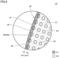
- Fig. 9 is an enlarged view of a region IX shown in Fig. 8 .
- Fig. 10 is a schematic diagram showing a thickness distribution of the upper layer portion of the sockliner shown in Fig. 1 .
- the base layer portion 10 of the sockliner 1A is formed of a three-dimensional mesh structure body 3A in which a plurality of unit structures 4A each having a three-dimensional lattice structure are repeatedly arranged. More specifically, the plurality of unit structures 4A are repeatedly arranged in a regular and continuous manner in each of a width direction (an X direction shown in the figure), a depth direction (a Y direction shown in the figure), and a height direction (a Z direction shown in the figure). In Fig. 7 , only the three adjacent unit structures 4A in the width direction, the depth direction, and the height direction are extracted and shown, in which each cutaway surface is shown in a dark color.
- the unit structure 4A having a three-dimensional lattice structure has a three-dimensional shape in which a plurality of columns extending in prescribed directions are connected to each other.
- Various structures can be applicable as the unit structure 4A.
- various kinds of structures are applicable, such as a rectangular parallelepiped lattice, a diamond lattice, an octahedral lattice, a double pyramid lattice, or a lattice having various supports added thereto.
- the unit structure 4A shown in the figure is obtained by adding a central support to a rectangular parallelepiped lattice.
- each of the unit structures 4A is formed of the three-dimensional mesh structure body 3A as described above, it is preferable to deform each of the unit structures 4A as required such that the outer shape of the three-dimensional mesh structure body 3A conforms to the outer shape of the sockliner 1A. This allows the sockliner 1A to have a smooth outer surface.
- the base layer portion 10 configured as described above is disposed in the lower portion of the sockliner 1A to thereby allow the sockliner 1A to have high deformability, which makes it possible to obtain a sockliner achieving excellent wearing comfort with excellent shock absorbing performance and also enhanced in stability during wearing of the shoe. Further, the base layer portion 10 having the above-described configuration makes it possible to obtain a sockliner that is lightweight considering the size of the sockliner and also excellent in air permeability.
- the occupied volume ratio of the base layer portion 10 is preferably 5% or more and 50% or less. This configuration allows the sockliner 1A to have high deformability, and further, to be reduced in weight and improved in air permeability.
- the upper layer portion 20 formed of a sheet-like structure body includes a through-hole group including a plurality of holes 24 penetrating through the upper layer portion 20 in its thickness direction.
- Each of the plurality of holes 24 included in the through-hole group is exposed at the upper surface 21 of the upper layer portion 20 and faces the base layer portion 10 along the lower surface 22 of the upper layer portion 20.
- Most of the plurality of holes 24 are in communication with holes provided on the inside of and in the outer surface of the base layer portion 10 along the boundary surface between the upper layer portion 20 and the base layer portion 10.
- each of the plurality of holes 24 included in the through-hole group is located inward from the peripheral edge of the upper layer portion 20 without reaching the peripheral edge (more specifically, the peripheral surface 23) of the upper layer portion 20.
- all of the plurality of holes 24 are located inward at a distance from the peripheral surface 23 and are completely closed in the direction orthogonal to the up-down direction.
- the plurality of holes 24 included in the through-hole group are arranged substantially uniformly in the entire area of the upper layer portion 20 when viewed in the up-down direction of the sockliner 1A. In other words, distribution of the plurality of holes 24 for each part of the sockliner 1A is not uneven but is at a substantially constant density.
- the holes located in the region on the front end area of the forefoot portion R1 are arranged substantially radially in dotted lines with respect to a substantially central position P1 of the forefoot portion R1 as a base point
- the holes located in the region on the rear end area of the rearfoot portion R3 are arranged substantially radially in dotted lines with respect to a substantially central position P2 of the rearfoot portion R3 as a base point.
- the holes located in the region on the rear end area of the forefoot portion R1 are arranged substantially in a matrix
- the holes located in the midfoot portion R2 are arranged substantially in a matrix
- the holes located in the region on the front end area of the rearfoot portion R3 are arranged substantially in a matrix.
- the plurality of holes 24 are arranged substantially uniformly in the entire area of the upper layer portion 20.
- the plurality of holes 24 are provided in dotted lines so as to substantially linearly connect the substantially central position P1 of the forefoot portion R1 to the substantially central position P2 of the rearfoot portion R3, and the plurality of other holes 24 are provided in dotted lines at positions along closed curves further surrounding, in layers, these substantially linearly arranged holes 24.
- the plurality of holes 24 are located substantially uniformly in the entire area of the upper layer portion 20.
- the through-hole group including the plurality of holes 24 includes an outermost hole group including a plurality of holes 24a located closest to the peripheral edge of the upper layer portion 20 so as to overlap with the surrounding region A1 and to align along the peripheral edge of the upper layer portion 20.
- each of the plurality of holes 24a included in the outermost hole group is located inward from the peripheral edge of the upper layer portion 20 without reaching the peripheral edge of the upper layer portion 20, the plurality of holes 24a are provided to overlap with the surrounding region A1 so as to be located close to the peripheral edge of the upper layer portion 20 (i.e., the peripheral surface 23 of the upper layer portion 20).
- a part of each of the plurality of holes 24a included in the outermost hole group may overlap with the surrounding region A1, or the plurality of holes 24a may entirely overlap with the surrounding region A1.
- the plurality of holes 24a included in the outermost hole group are located closer to the peripheral edge of the upper layer portion 20 than the plurality of holes 24 provided to completely overlap with an inner region A2 located on the inside of the surrounding region A1.
- the upper layer portion 20 covers the base layer portion 10 having the upper surface 11 provided with a large number of fine protrusions and recesses due to the presence of a large number of holes on the inside of and in the outer surface of the base layer portion 10, and also, the upper surface of the sockliner 1A that comes into contact with the user's foot sole is formed of the smooth upper surface 21 of the upper layer portion 20 made of a sheet-like structure body. Therefore, a sockliner achieving an excellent feel of contact for a foot and excellent wearing comfort can be obtained.
- these plurality of holes 24 are provided substantially uniformly in the upper layer portion 20, so that excellent wearing comfort can be achieved without causing uncomfortable feeling to the user who is wearing the shoes.
- the plurality of holes 24a included in the outermost hole group in the through-hole group are located to overlap with the surrounding region A1 and also do not reach the peripheral edge of the upper layer portion 20.
- none of the holes provided in the upper layer portion 20 reaches the peripheral edge of the upper layer portion 20. Accordingly, damage to the peripheral edge that is continuously rubbed against the shoe 100 worn by the user can be significantly suppressed, with the result that a sockliner excellent in durability can be obtained.
- the upper layer portion 20 configured as described above in the upper portion of the sockliner 1A, the area of contact with the foot sole of the user wearing the shoe increases. Thereby, a sockliner enhanced in stability for the foot of the user wearing the shoe can be obtained, and further, a sockliner capable of effectively dispersing the foot pressure can also be obtained. Further, since the base layer portion 10 formed of the three-dimensional mesh structure body 3A is protected by the upper layer portion 20, a sockliner excellent in durability can also be obtained in this respect.
- the upper layer portion 20 of the sockliner 1A is provided with the plurality of holes 24 as described above, an effect of less easily causing a shape defect can be achieved when the sockliner 1A is manufactured by a vat polymerization three-dimensional additive manufacturing method, with the result that the sockliner 1A can be manufactured with high accuracy, which will be described later in detail.
- the plurality of holes 24 included in the through-hole group preferably have a cylindrical shape or an elliptic cylindrical shape.
- the shapes of the plurality of holes 24 are not limited thereto and may be a polygonal column such as a triangular column or a quadrangular column, or may be other shapes.
- the size of each of the holes 24 included in the through-hole group is not particularly limited, for example, its maximum outer dimension in a plan view is preferably about 1.0 mm or more and 5.0 mm or less, and is about 2.0 mm by way of example.
- the plurality of holes 24 included in the through-hole group are preferably formed to be substantially larger in opening area toward the peripheral edge of the upper layer portion 20 when viewed in the up-down direction of the sockliner 1A. This configuration can prevent an extremely large difference in rigidity between the central portion and the peripheral edge of the upper layer portion 20 of the sockliner 1A.
- the surface area of the upper surface 21 of the upper layer portion 20 is defined as Sa and the total opening area of the plurality of holes 24 included in the through-hole group in the upper surface 21 of the upper layer portion 20 is defined as Sb
- Sa and Sb preferably satisfy the condition of 0.15 ⁇ Sb/(Sa + Sb) ⁇ 0.70.
- the thickness of the upper layer portion 20 is preferably 0.5 mm or more and 2.0 mm or less. This is for the purpose of reducing the weight and ensuring the durability while ensuring the flexibility of the upper layer portion 20. In this case, the thickness of the upper layer portion 20 may be the same in the entire region but may be different for each part. In the sockliner 1A according to the present embodiment, the upper layer portion 20 is not uniform in thickness and is configured to have a thickness distribution, specifically, in the range of 0.8 mm or more and 1.4 mm or less.
- the upper layer portion 20 is configured to be thicker in a substantially central region in the front-rear direction of the forefoot portion R1 than in a region adjacent to the substantially central region.
- the substantially central region includes a portion that supports a part of the foot sole corresponding to a metacarpophalangeal (MP) joint of the user (a portion denoted by a symbol MP in the figure).
- MP metacarpophalangeal
- the configuration as described above can enhance the durability of the portion included in the sockliner 1A that receives relatively high foot pressure during landing on the ground and for supporting the part of the foot sole corresponding to the MP joint of the user, and also can effectively disperse the foot pressure, so that high shock absorbing performance can be achieved.
- Figs. 11A to 11C are schematic diagrams each illustrating a mapping method for the plurality of holes provided in the upper layer portion of the sockliner shown in Fig. 1 .
- the following describes a mapping method for the plurality of holes 24 provided in the upper layer portion 20 when manufacturing the sockliner 1A according to the present embodiment.
- the sockliner 1A may be manufactured based on the shape data about a standard foot sole prepared in advance for each size of a foot, or may be manufactured based on the shape data about the foot sole obtained by measuring the actual user's foot sole so as to conform to the user's foot.
- the following describes a method of mapping the plurality of holes 24 to the sockliner 1A based on the shape data about the foot sole obtained by measuring the actual user's foot sole.
- a sockliner model M is generated based on the shape data about the user's foot sole obtained by the imaging means or the like.
- the sockliner model M includes an upper surface, a lower surface, and a peripheral surface.
- the upper surface corresponds to the upper surface 21 of the upper layer portion 20.
- the upper surface of the sockliner model M may be formed of one or more curved surfaces, flat surfaces, or a combination thereof, but is normally formed as a three-dimensional surface conforming to the shape of the user's foot sole.
- the upper surface of the generated sockliner model M is divided into regions. Specifically, in the present mapping method, the upper surface of the sockliner model M is divided into a plurality of quadrangular divided regions DA adjacent to each other. Thus, the upper surface of the sockliner model M is paved with a large number of quadrangular divided regions DA.
- the upper surface is preferably divided into regions, for example, such that the area and the side lengths of each quadrangular divided region DA, the internal angle of each vertex thereof, and the like fall within their prescribed ranges. In this way, the entire upper surface of the sockliner model M is substantially equally divided into regions.
- a circular or elliptical drawn line 24' having a prescribed size is plotted at a central position in each of the plurality of quadrangular divided regions DA.
- This drawn line 24' corresponds to an outline of each of the plurality of holes 24 provided in the upper layer portion 20, and thus, mapping of the plurality of holes 24 provided in the upper layer portion 20 is completed.
- each of the plurality of holes 24a to be arranged in the portion closest to the peripheral edge of the upper layer portion 20 i.e., the plurality of holes included in the outermost hole group
- the surrounding region A1 i.e., the region included between the peripheral edge of the upper layer portion 20 and the position offset by 4.0 mm inward from the peripheral edge of the upper layer portion 20.
- Figs. 12, 13 , and 14 are schematic diagrams showing the method of manufacturing the sockliner according to the first embodiment, and respectively illustrate the states of the start, middle, and end of additive manufacturing of the sockliner by the three-dimensional additive manufacturing method. The following describes the method of manufacturing the sockliner according to the present embodiment with reference to Figs. 12 to 14 .
- the sockliner 1A is formed of the additively manufactured product 2 made of a single component produced by the vat polymerization three-dimensional additive manufacturing method.
- the sockliner 1A can be additively manufactured, for example, by using a three-dimensional additive manufacturing apparatus 1000 as shown in Figs. 12 to 14 .
- the three-dimensional additive manufacturing apparatus 1000 serves to produce an additively manufactured product by the vat polymerization three-dimensional additive manufacturing method.
- a photocurable liquid resin or liquid rubber that is hardened by light of a specific wavelength is used as a main raw material, to which this light of a specific wavelength is applied to thereby sequentially stack hardened portions, and thus, an additively manufactured product having a desired shape is produced.
- the light of a specific wavelength used herein may be ultraviolet light, in which case an ultraviolet curing resin or rubber is used as a main raw material.
- the above-mentioned liquid resin or liquid rubber as a main raw material is not limited to one-component type but may be two-component type or the like.
- the three-dimensional additive manufacturing apparatus 1000 includes a light source (not shown), a storage tank 1001, a platform 1002, and a hoisting and lowering mechanism 1003.
- the storage tank 1001 serves to store a liquid resin 200 or the like as a raw material
- the platform 1002 serves to move the additively manufactured product 2 while holding it.
- the hoisting and lowering mechanism 1003 serves to move the platform 1002 upward and downward.
- the platform 1002 is first moved by the hoisting and lowering mechanism 1003, and thereby, the lower surface of the platform 1002 is placed in contact with the liquid surface of the liquid resin 200 or the like.
- light of a specific wavelength emitted from the light source is applied to the vicinity of the liquid surface of the liquid resin 200 or the like in a prescribed pattern for exposure to light.
- a portion of the liquid resin 200 or the like that is located in the vicinity of the liquid surface is hardened in a layered manner while adhering to the lower surface of the platform 1002, so that a first hardened layer is formed.
- the platform 1002 is moved upward (i.e., in the direction indicated by an arrow DR1 in the figure) by a prescribed amount by the hoisting and lowering mechanism 1003, to cause the lower surface of the first hardened layer to be placed in contact with the liquid surface of the liquid resin 200 or the like.
- light of a specific wavelength emitted from the light source is applied to the vicinity of the liquid surface of the liquid resin 200 or the like in a prescribed pattern for exposure to light.
- a portion of the liquid resin 200 or the like that is located in the vicinity of the liquid surface is hardened in a layered manner while adhering to the lower surface of the first hardened layer, so that a second hardened layer is formed.
- a plurality of hardened layers are sequentially stacked in the downward direction (i.e., in the direction indicated by an arrow DR2 shown in the figure) as shown in Fig. 13 , and thereby, additive manufacturing of the sockliner 1A proceeds.
- the base layer portion 10 and the upper layer portion 20 each are sequentially additively manufactured simultaneously.
- the platform 1002 is lifted further upward by the hoisting and lowering mechanism 1003. Then, the sockliner 1A is pulled away from the liquid resin 200 or the like stored in the storage tank 1001 and removed from the three-dimensional additive manufacturing apparatus 1000. At this time, the sockliner 1A that has been additively manufactured is not sufficiently hardened but is still relatively soft. Thus, the removed sockliner 1A is separately washed and heated, then substantially hardened, and further washed and dried, and thus, production of the sockliner 1A completes.
- the base layer portion 10 and the upper layer portion 20 each are simultaneously additively manufactured sequentially from the rear end area of the rearfoot portion R3 toward the front end area of the forefoot portion R1 by the vat polymerization three-dimensional additive manufacturing method.
- the front-rear direction of the sockliner 1A coincides with the direction in which a plurality of hardened layers are sequentially stacked and the sockliner 1A is additively manufactured (i.e., in the direction indicated by the arrow DR2 shown in the figure).
- the footprint required for additively manufacturing the sockliner 1A on the platform 1002 becomes relatively small, and thereby, a plurality of sockliners 1A can be simultaneously additively manufactured as shown in the figure.
- manufacturing the sockliner 1A according to this manufacturing method can shorten the tact time and thereby can reduce the manufacturing cost, so that a method of manufacturing the sockliner 1A suitable for mass production can be implemented.
- a support portion 2' as shown in Figs. 13 and 14 needs to be formed separately from the sockliner 1A so as to maintain the shape of the relatively soft sockliner 1A during additive manufacturing.
- the support portion 2' is cut away and removed from the sockliner 1A after additive manufacturing of the sockliner 1A.
- Fig. 15 is a schematic diagram showing another method of manufacturing the sockliner according to the first embodiment. Referring to Fig. 15 , the following describes another method of manufacturing the sockliner according to the present embodiment.
- another method of manufacturing the sockliner according to the present embodiment is to manufacture the sockliner 1A (formed of a single component) using the three-dimensional additive manufacturing apparatus 1000 by the vat polymerization three-dimensional additive manufacturing method, similarly to the method of manufacturing the sockliner according to the above-described present embodiment (i.e., the method of manufacturing the sockliner as described with reference to Figs. 12 to 14 ).
- another method of manufacturing the sockliner according to the present embodiment is different from the method of manufacturing the sockliner according to the present embodiment in terms of the direction in which the sockliner 1A is additively manufactured.
- a part of the base layer portion 10 is sequentially additively manufactured from the lower surface 12 side of the base layer portion 10 in the direction orthogonal to the lower surface 12 of the base layer portion 10, and subsequently, a remaining part of the base layer portion 10 and a part of the upper layer portion 20 are sequentially additively manufactured simultaneously, and further subsequently, a remaining part of the upper layer portion 20 is sequentially additively manufactured.
- the up-down direction of the sockliner 1A coincides with the direction in which the plurality of hardened layers are sequentially stacked (in the direction indicated by the arrow DR2 shown in the figure).
- the footprint required to additively manufacture the sockliner 1A on the platform 1002 becomes relatively large, which makes it difficult to additively manufacture a plurality of sockliners 1A simultaneously.
- the support portion 2' as shown in Figs. 13 and 14 is no longer required, the tact time can be shortened in this respect, and the problem of producing waste materials (i.e., the support portion 2' having been cut away from the sockliner 1A) does not occur, so that the manufacturing cost can be reduced in this sense.
- the sockliner 1A is additively manufactured by a vat polymerization three-dimensional additive manufacturing method. During this additive manufacturing, the plurality of holes 24 as described above are provided in the upper layer portion 20 of the sockliner 1A.
- the plurality of holes 24 are in communication with the holes provided on the inside of and in the outer surface of the base layer portion 10 along the boundary surface between the upper layer portion 20 and the base layer portion 10.
- the plurality of holes 24 serve as discharge holes through which unhardened liquid resin remaining inside the base layer portion 10 is discharged during the above-mentioned washing process. Therefore, during the heating process performed after the washing process, remaining of the unhardened liquid resin inside the base layer portion 10 can be suppressed, so that shape defects are less likely to occur, with the result that the sockliner 1A having an intended shape can be manufactured.
- sockliner 1A As described above, employing the sockliner 1A according to the present embodiment and the method of manufacturing the same makes it possible to provide a sockliner achieving high performance, an excellent feel of contact for a foot, and excellent durability, and a method of manufacturing the sockliner.
- Figs. 16 and 17 are schematic diagrams each showing the thickness distribution of an upper layer portion of a sockliner according to each of the first and second modifications. Referring to Figs. 16 and 17 , the following describes sockliners 1A1 and 1A2 according to the first and second modifications based on the above-described first embodiment.
- the sockliners 1A1 and 1A2 according to the first and second modifications are different in configuration from the sockliner 1A according to the first embodiment only in that the upper layer portion 20 is different in thickness distribution.
- the upper layer portion 20 is not only configured to be thicker in a substantially central region in the front-rear direction of the forefoot portion R1 that includes a portion supporting a part of the foot sole corresponding to the MP joint of the user (a portion indicated by a symbol MP in the figure) than in a region adjacent to the substantially central region, but is also configured to be thicker in the rearfoot portion R3 than in a portion adjacent to the rearfoot portion R3.
- the rearfoot portion R3 serves to support the heel portion of the user as described above.
- the configuration as described above can enhance the durability of the portion included in the sockliner 1A that receives relatively high foot pressure during landing on the ground and for supporting the heel portion and the part of the foot sole corresponding to the MP joint of the user, and also can effectively disperse the foot pressure, so that high shock absorbing performance can be achieved.
- the upper layer portion 20 is configured to be thicker in the portion that supports the part on the lateral foot side in the foot sole of the user than in the portion that supports the part on the medial foot side in the foot sole of the user.
- the sockliner 1A is more rigid in the portion on the lateral foot side than in the portion on the medial foot side, which makes it possible to effectively suppress the collapse of the heel portion (which is called pronation) occurring when the user's foot lands on the ground, so that the support performance can be enhanced.
- the thickness distribution of the upper layer portion 20 in the sockliner can be changed as appropriate, and may be optimized in accordance with the performance required for the sockliner.
- the performance required for the sockliner differs depending on the scene in which the footwear equipped with the sockliner is used (daily walking, training, sports competition, and the like).
- the performance required for the sockliner is the performance required depending on various actions (for example, a push-off action, a turn-back action, lateral moving action, and the like) required depending on the specific type of sports.
- the thickness distribution of the base layer portion 10 can also be changed as appropriate and may be optimized in accordance with the performance required for the sockliner.
- Figs. 18A to 18C are schematic diagrams each showing a mapping method for a plurality of holes provided in an upper layer portion of a sockliner according to the third modification. Referring to Figs. 18A to 18C , the following describes an example of another mapping method different from the mapping method for the plurality of holes 24 provided in the upper layer portion 20 that has been described above in the first embodiment.
- a sockliner model M is generated based on the shape data about the user's foot sole that is obtained by the imaging means or the like.
- the upper surface of the generated sockliner model M is divided into regions.
- the upper surface of the sockliner model M is divided into a plurality of triangular divided regions DA adjacent to each other.
- the upper surface of the sockliner model M is paved with a large number of triangular divided regions DA.
- a circular or elliptical drawn line 24' having a prescribed size is plotted at a central position in each of the plurality of triangular divided regions DA.
- This drawn line 24' corresponds to the outline of each of the plurality of holes 24 provided in the upper layer portion 20, and thus, mapping of the plurality of holes 24 provided in the upper layer portion 20 is completed.
- Adopting such a mapping method also makes it possible to easily manufacture a sockliner 1A3 in which the plurality of holes 24 included in the through-hole group are arranged substantially uniformly in the entire area of the upper layer portion 20 when viewed in the thickness direction of the upper layer portion 20, as in the above-described first embodiment.
- Fig. 19 is a schematic diagram for illustrating a three-dimensional structure of a base layer portion in a sockliner according to the fourth modification. Referring to Fig. 19 , the following describes a sockliner 1A4 according to the fourth modification based on the above-described first embodiment.
- the sockliner 1A4 according to the fourth modification is different in configuration from the sockliner 1A according to the first embodiment only in that the base layer portion 10 is different in three-dimensional structure.
- the base layer portion 10 of the sockliner 1A4 according to the fourth modification is formed of a three-dimensional mesh structure body 3B in which a plurality of unit structures 4B each having a three-dimensional wall structure are repeatedly arranged. More specifically, the plurality of unit structures 4B are repeatedly arranged in a regular and continuous manner in each of the width direction (the X direction shown in the figure), the depth direction (the Y direction shown in the figure), and the height direction (the Z direction shown in the figure). In Fig. 19 , only three unit structures 4B adjacent to each other in the width direction, the depth direction, and the height direction are selectively shown, in which each cutaway surface is shown in a dark color.
- the unit structure 4B having a three-dimensional wall structure has a three-dimensional shape formed by a wall having an outer shape defined by a pair of parallel curved surfaces.
- the unit structure 4B shown in the figure is obtained by adding a thickness to a Schwartz P structure, which is a type of mathematically defined triply periodic minimal surface, as a base structure.
- a minimal surface is defined as a curved surface that is minimal in area among the curved surfaces having a given closed curve as a boundary.
- the base layer portion 10 configured as described above is disposed in the lower portion of the sockliner 1A4 to thereby allow the sockliner 1A4 to have high deformability, which makes it possible to obtain a sockliner achieving excellent wearing comfort with excellent shock absorbing performance and also enhanced in stability during wearing of the shoe. Further, the base layer portion 10 having the above-described configuration makes it possible to obtain a sockliner that is lightweight considering the size of the sockliner and also excellent in air permeability.
- the unit structure 4B having a three-dimensional wall structure may be a structure obtained by adding a thickness to a triply periodic minimal surface such as a gyroid structure or a Schwartz D structure as a base structure.
- applicable examples of the unit structure 4B having a three-dimensional wall structure may be a structure having a three-dimensional shape formed by a wall having an outer shape defined by a pair of parallel flat surfaces. Specific examples in this case may be a structure obtained by adding a thickness to an octet structure, a cubic structure, or the like.
- Fig. 20 is a perspective view of a sockliner according to the second embodiment as viewed from the obliquely upper right front side.
- Fig. 21 is a schematic cross-sectional view of the sockliner shown in Fig. 20 taken along a line XXI-XXI shown in Fig. 20
- Fig. 22 is an enlarged view of a region XXII shown in Fig. 21 .
- Fig. 23 is an exploded perspective view of the sockliner shown in Fig. 20 .
- a sockliner 1B according to the present embodiment will be hereinafter described.
- the sockliner 1B according to the present embodiment is dispose on the shoe 100 for use in place of the sockliner 1A according to the first embodiment.
- the sockliner 1B includes a base layer portion 10, an upper layer portion 20, and a liner 30.
- the base layer portion 10 and the upper layer portion 20 are formed of a single component similarly to the sockliner 1A according to the above-described first embodiment, and are formed of an additively manufactured product 2 produced by a vat polymerization three-dimensional additive manufacturing method.
- the liner 30 is fixed to the additively manufactured product 2 formed of a single component.
- the liner 30 includes: a base fabric portion 31 made of a woven fabric or a nonwoven fabric; and a sticky adhesive layer 32 provided on a lower surface of the base fabric portion 31.
- the sticky adhesive layer 32 is affixed to the upper surface 21 of the upper layer portion 20 and thereby the liner 30 is fixed to the upper layer portion 20.
- the liner 30 covers the upper surface 21 of the upper layer portion 20, and accordingly, also covers a through-hole group including a plurality of holes 24 provided in the upper layer portion 20 (particularly see Figs. 21 and 22 ).
- the upper surface of the sockliner 1B that comes into contact with the foot sole of the user wearing a shoe is configured of the base fabric portion 31 of the liner 30. Since the base fabric portion 31 is more flexible than the upper layer portion 20, the base fabric portion 31 configured as described above can contribute to a sockliner that achieves a more excellent feel of contact for a foot and more excellent wearing comfort than those achieved by the sockliner 1A according to the first embodiment. Since the base fabric portion 31 made of a woven fabric or a nonwoven fabric has a surface slipping more easily than the upper layer portion 20, the base fabric portion 31 configured as described above allows the user's foot to be smoothly inserted into the shoe 100 when the user wears the shoe 100.
- the sticky adhesive layer 32 is preferably made of glue that is applied in advance onto the lower surface of the base fabric portion 31. This can prevent in advance the sticky adhesive layer 32 from entering and blocking the holes 24 provided in the upper layer portion 20, so that a decrease in air permeability can be suppressed. Further, when the sticky adhesive layer 32 is provided not entirely but partially on the lower surface of the base fabric portion 31, some of the plurality of holes 24 provided in the upper layer portion 20 can be prevented from being covered by the sticky adhesive layer 32 while the base fabric portion 31 is fixed to the upper layer portion 20, with the result that air permeability can be more reliably ensured.
- the adhesive agent when the base fabric portion 31 is fixed with an adhesive agent to the upper layer portion 20, the adhesive agent may enter the holes 24 provided in the upper layer portion 20, which may decrease the air permeability.
- the adhesive agent if an adhesive agent is applied not entirely but partially onto the lower surface of the base fabric portion 31, the adhesive agent can be prevented from entering some of the plurality of holes 24 provided in the upper layer portion 20 while the base fabric portion 31 is fixed to the upper layer portion 20. Thereby, a decrease in air permeability can be suppressed to a considerable degree.
- the material of the base fabric portion 31 is not particularly limited, and specific examples thereof include: synthetic fibers such as polyester fibers or nylon fibers excellent in air permeability, heat dissipation, wear resistance and the like; and natural fibers such as cotton excellent in air permeability, moisture absorbing performance, and the like.
- the thickness of the base fabric portion 31 is not particularly limited, but the base fabric portion 31 is preferably less in thickness than the upper layer portion 20 in order to reduce the friction and improve the texture between the foot sole and the base fabric portion 31.
- the thickness of the base fabric portion 31 is preferably 0.1 mm or more and 2.0 mm or less, and is about 1.0 mm by way of example.
- the material of the sticky adhesive layer 32 is not particularly limited, and suitably applicable examples thereof include a material containing an acrylic resin, a urethane resin, a silicone resin, rubber, or the like as a main component.
- the thickness of the sticky adhesive layer 32 is not particularly limited but is, for example, preferably 0.01 mm or more and 0.5 mm or less, and is about 0.1 mm by way of example.
- the sockliner 1B configured as described above can also achieve high performance, an excellent feel of contact for a foot, and excellent durability as with the sockliner 1A according to the first embodiment.
- a sockliner includes: a forefoot portion that supports a toe portion and a ball portion of a foot of a user; a midfoot portion that supports an arch portion of the foot of the user; and a rearfoot portion that supports a heel portion of the foot of the user, the sockliner being dispose on an inner bottom surface of footwear for use, the sockliner including:
- the holes included in the through-hole group are arranged substantially uniformly in an entire area of the upper layer portion when viewed in a thickness direction of the upper layer portion.
- the holes included in the through-hole group are formed to be substantially larger in opening area toward the peripheral edge of the upper layer portion when viewed in the thickness direction of the upper layer portion.
- the holes included in the through-hole group have a cylindrical shape or an elliptic cylindrical shape.
- an occupied volume ratio of the base layer portion is 5% or more and 50% or less.
- the upper layer portion is not uniform in thickness.
- a portion that supports a part of a foot sole corresponding to an MP joint of the user is thicker than a portion adjacent to the portion.
- a portion included in the rearfoot portion is thicker than a portion adjacent to the portion.
- a portion that supports a part on a lateral foot side of a foot sole of the user is thicker than a portion that supports a part on a medial foot side of the foot sole of the user.
- the base layer portion and the upper layer portion are formed of a single component.
- the base layer portion and the upper layer portion that are formed of a single component are formed of a single additively manufactured product produced by a vat polymerization three-dimensional additive manufacturing method.
- the sockliner according to any one of Supplementary Notes 1 to 13 further includes a liner that covers an upper surface of the upper layer portion, wherein the liner is formed of a woven fabric or a nonwoven fabric.
- a method of manufacturing the sockliner according to Supplementary Note 13 includes:
- a method of manufacturing the sockliner according to Supplementary Note 13 includes:
- the base layer portion 10 and the upper layer portion 20 that are formed of a single component are produced by a vat polymerization three-dimensional additive manufacturing method, but the base layer portion 10 and the upper layer portion 20 can also naturally be produced by other type of three-dimensional additive manufacturing method. Further, the base layer portion 10 and the upper layer portion 20 do not necessarily have to be formed of a single component, but may be separately produced and then joined to each other.
- the base layer portion 10 is preferably produced by a three-dimensional additive manufacturing method in terms of its structure, but the upper layer portion 20 does not necessarily have to be produced by a three-dimensional additive manufacturing method in terms of its structure, and can be produced by various methods such as injection molding or sheet molding.
- first and second embodiments and the modifications thereof have been described above with reference to an example in which the plurality of holes 24 included in the through-hole group are provided substantially uniformly in the entire area of the upper layer portion 20, but the plurality of holes 24 do not necessarily have to be substantially uniformly provided and may be positioned unevenly in some regions on the upper layer portion 20.
- a plurality of holes 24 may be provided in the forefoot portion R1 and the rearfoot portion R3 but may not be provided in the midfoot portion R2.
- the through-hole group including the plurality of holes 24 provided in the forefoot portion R1 and the rearfoot portion R3 needs to include the outermost hole group including the plurality of holes 24a overlapping with the surrounding region A1 and arranged along the peripheral edge of the upper layer portion 20.
- all of the plurality of holes 24 included in the through-hole group provided in the upper layer portion 20 may be provided in the outermost hole group that includes the plurality of holes 24a overlapping with the surrounding region A1 and arranged along the peripheral edge of the upper layer portion 20 (i.e., holes 24 overlapping with only the inner region A2 are not provided).
- the outer surface of the base layer portion 10 may be provided with symbol portions or design portions such as characters, logos, patterns, and authentication codes as options by additive manufacturing.
- these symbol portions and design portions are preferably provided on the peripheral surface 13 of the base layer portion 10, or provided on a relatively thick portion of the base layer portion 10 or a portion of the base layer portion 10 that corresponds to a relatively thick portion of the upper layer portion 20 (for example, a portion close to the rear end of the forefoot portion R1, a portion close to the front end of the midfoot portion R2, a portion extending from the rear end of the midfoot portion R2 to the front end of the rearfoot portion R3, and the like).
- the second embodiment has been described above with reference to an example configuration in which the liner 30 is affixed onto the upper layer portion 20 with the sticky adhesive layer 32 provided on the liner 30, but the base fabric portion 31 may be fixed to the upper layer portion 20 by other methods typified, for example, by bonding through application of an adhesive agent.
Abstract
A sockliner (1A) includes: a base layer portion (10) formed of a three-dimensional mesh structure body; and an upper layer portion (20) formed of a sheet-like structure body that covers an upper surface of the base layer portion (10). The upper layer portion (20) includes a through-hole group including a plurality of holes (24), and each of the holes (24) is located inward from a peripheral edge of the upper layer portion (20) without reaching the peripheral edge. In a case where a surrounding region is defined as a region between the peripheral edge and a position offset by 4.0 mm inward from the peripheral edge, the through-hole group includes an outermost hole group including a plurality of holes located closest to the peripheral edge so as to overlap with the surrounding region and to align along the peripheral edge.
Description
- The present disclosure relates to a sockliner and a method of manufacturing the sockliner.
- For example,
U.S. Patent Application Publication No. 2018/228401 discloses a sockliner manufactured by a three-dimensional additive manufacturing method. The sockliner is manufactured in the following manner. Specifically, the foot pressure of a foot of a user who stands upright is first measured at each site on the foot sole of the user. Then, a cell corresponding to the measured foot pressure is selected from a plurality of cells each formed of a three-dimensional lattice structure or the like prepared in advance, and then mapped to each site on the corresponding position on the foot sole, to thereby generate three-dimensional mesh data of the sockliner, and then additively manufacture a sockliner based on the generated three-dimensional mesh data by a three-dimensional additive manufacturing method. - The sockliner disclosed in the above-mentioned publication is manufactured according to the above-mentioned manufacturing method, with the result that not only a large number of holes are present inside the sockliner but also a large number of holes are exposed to the outside over the entire outer surface of the sockliner. Although such a large number of holes contribute to improvement in performance of the sockliner such as improvement in shock absorbing performance and reduction in weight, these holes may adversely affect the wearing comfort of the user if no measures are taken.
- In other words, in the sockliner disclosed in the above-mentioned publication, a large number of holes of various sizes are present also on the upper surface of the sockliner that comes into contact with the foot sole. This causes a problem that what is called a feel of contact for the foot may not be excellent when the user wears footwear equipped with this sockliner.
- In addition, since the peripheral edge of the sockliner in a plan view of the upper surface is also continuously rubbed against the footwear worn by the user. Thus, a large number of holes provided to reach the peripheral edge tend to cause damage to the sockliner starting from this peripheral edge, which may lead to a problem of poor durability.
- On the other hand, in the case where no hole is provided in the peripheral edge of the sockliner in order to solve the above-described problem, considering that the peripheral edge is thinly formed to conform to the shape of the inner bottom surface of the footwear, not only the shock absorbing performance becomes insufficient in the peripheral edge, but also the portion in this peripheral edge is more rigid than other portions. Accordingly, the user who wears the footwear may feel uncomfortable.
- Thus, the present disclosure has been made to solve the above-described problems, and an object of the present disclosure is to provide a sockliner achieving high performance, an excellent feel of contact for a foot, and excellent durability, and a method of manufacturing the sockliner.
- A sockliner according to the present disclosure includes: a forefoot portion that supports a toe portion and a ball portion of a foot of a user; a midfoot portion that supports an arch portion of the foot of the user; and a rearfoot portion that supports a heel portion of the foot of the user. The sockliner is also dispose on an inner bottom surface of footwear for use. The sockliner includes: a base layer portion disposed with a lower surface facing the inner bottom surface of the footwear; and an upper layer portion configured to cover an upper surface of the base layer portion. The base layer portion includes a three-dimensional mesh structure body in which a unit structure is repeatedly arranged in multiple arrays, the unit structure having at least one of a three-dimensional lattice structure and a three-dimensional wall structure. The upper layer portion is formed of a sheet-like structure body including a through-hole group including a plurality of holes penetrating through the upper layer portion in a thickness direction of the upper layer portion. Each of the holes included in the through-hole group is located inward from a peripheral edge of the upper layer portion without reaching the peripheral edge of the upper layer portion. In the sockliner according to the present disclosure, in a case where a surrounding region is defined as a region between the peripheral edge of the upper layer portion and a position offset by 4.0 mm inward from the peripheral edge of the upper layer portion, the through-hole group includes an outermost hole group including a plurality of holes located closest to the peripheral edge of the upper layer portion so as to overlap with the surrounding region and to align along the peripheral edge of the upper layer portion.
- A method of manufacturing a sockliner according to a first aspect of the present disclosure is a method for manufacturing the sockliner according to the present disclosure, in which the base layer portion and the upper layer portion are formed of a single component, and the base layer portion and the upper layer portion that are formed of a single component are formed of a single additively manufactured product produced by a vat polymerization three-dimensional additive manufacturing method. The method includes: producing the base layer portion; and producing the upper layer portion. In the method of manufacturing the sockliner according to the first aspect of the present disclosure, in the producing of the base layer portion and the producing of the upper layer portion, by a vat polymerization three-dimensional additive manufacturing method, the base layer portion and the upper layer portion are simultaneously and sequentially accumulated from a rear end area of the rearfoot portion to a front end area of the forefoot portion by additive manufacturing.
- A method of manufacturing a sockliner according to a second aspect of the present disclosure is a method for manufacturing the sockliner according to the present disclosure, in which the base layer portion and the upper layer portion are formed of a single component, and the base layer portion and the upper layer portion that are formed of a single component are formed of a single additively manufactured product produced by a vat polymerization three-dimensional additive manufacturing method. The method includes: producing the base layer portion; and producing the upper layer portion. In the method of manufacturing a sockliner according to the second aspect of the present disclosure, in the producing of the base layer portion and the producing of the upper layer portion, by a vat polymerization three-dimensional additive manufacturing method, at least a part of the base layer portion is simultaneously and sequentially accumulated from a side of the lower surface of the base layer portion in a direction orthogonal to the lower surface of the base layer portion, and subsequently, at least a part of the upper layer portion is simultaneously and sequentially accumulated by additive manufacturing.
- The foregoing and other objects, features, aspects, and advantages of the present disclosure will become apparent from the following detailed description of the present disclosure, which is understood in conjunction with the accompanying drawings.
-
-
Fig. 1 is a schematic diagram for illustrating a use mode of a sockliner according to a first embodiment. -
Fig. 2 is a perspective view of the sockliner shown inFig. 1 as viewed from the obliquely upper right front side. -
Fig. 3 is a perspective view of the sockliner shown inFig. 1 as viewed from the obliquely lower left rear side. -
Fig. 4 is a plan view of the sockliner shown inFig. 1 . -
Fig. 5 is a side view of the sockliner shown inFig. 1 as viewed from the lateral foot side. -
Fig. 6 is a partially cutaway perspective view of the sockliner shown inFig. 1 taken along a line VI-VI shown inFigs. 2 ,4 , and5 . -
Fig. 7 is a schematic diagram for illustrating a three-dimensional structure of a base layer portion of the sockliner shown inFig. 1 . -
Fig. 8 is a plan view showing only an upper layer portion of the sockliner shown inFig. 1 . -
Fig. 9 is an enlarged view of a region IX shown inFig. 8 . -
Fig. 10 is a schematic diagram showing a thickness distribution of the upper layer portion of the sockliner shown inFig. 1 . -
Figs. 11A to 11C are schematic diagrams each illustrating a mapping method for a plurality of holes provided in the upper layer portion of the sockliner shown inFig. 1 . -
Fig. 12 is a schematic diagram showing a state at the start of additive manufacturing of the sockliner by a three-dimensional additive manufacturing method in a method of manufacturing the sockliner according to the first embodiment. -
Fig. 13 is a schematic diagram showing a state in the middle of additive manufacturing of the sockliner by the three-dimensional additive manufacturing method in the method of manufacturing the sockliner according to the first embodiment. -
Fig. 14 is a schematic diagram showing a state at the end of additive manufacturing of the sockliner by the three-dimensional additive manufacturing method in the method of manufacturing the sockliner according to the first embodiment. -
Fig. 15 is a schematic diagram showing another method of manufacturing the sockliner according to the first embodiment. -
Fig. 16 is a schematic diagram showing a thickness distribution of an upper layer portion of a sockliner according to a first modification. -
Fig. 17 is a schematic diagram showing a thickness distribution of an upper layer portion of a sockliner according to a second modification. -
Figs. 18A to 18C are schematic diagrams each illustrating a mapping method for a plurality of holes provided in an upper layer portion of a sockliner according to a third modification. -
Fig. 19 is a schematic diagram for illustrating a three-dimensional structure of a base layer portion of a sockliner according to a fourth modification. -
Fig. 20 is a perspective view of a sockliner according to a second embodiment as viewed from the obliquely upper right front side. -
Fig. 21 is a schematic cross-sectional view of the sockliner shown inFig. 20 taken along a line XXI-XXI shown inFig. 20 . -
Fig. 22 is an enlarged view of a region XXII shown inFig. 21 . -
Fig. 23 is an exploded perspective view of the sockliner shown inFig. 20 . - The following describes embodiments of the present disclosure in detail with reference to the accompanying drawings. In the following embodiments, the same or common portions are denoted by the same reference characters in the figures, and the description thereof will not be repeated.
-
Fig. 1 is a schematic diagram for illustrating a use mode of a sockliner according to the first embodiment, andFigs. 2 and3 are perspective views of the sockliner shown inFig. 1 as viewed from the obliquely upper right front side and the obliquely lower left rear side, respectively.Fig. 4 is a plan view of the sockliner shown inFig. 1 , andFig. 5 is a side view of the sockliner shown inFig. 1 as viewed from the lateral foot side.Fig. 6 is a partially cutaway perspective view of the sockliner shown inFig. 1 taken along a line VI-VI shown inFigs. 2 ,4 , and5 . Referring toFigs. 1 to 6 , a schematic configuration of asockliner 1A according to the present embodiment will be first described. - As shown in
Fig. 1 , thesockliner 1A is placed for use, for example, on ashoe 100 as footwear. Theshoe 100 includes a sole 110 and an upper 120. When theshoe 100 is in use, thesockliner 1A is inserted into theshoe 100 through a topline 121 provided in the upper 120. Thus, thesockliner 1A is placed on an inner bottom surface of theshoe 100 such that the lower surface of thesockliner 1A faces the inner bottom surface, so that thesockliner 1A is disposed on theshoe 100. - While a user wears the
shoe 100, a foot sole of the user is placed on the upper surface of thesockliner 1A. Thereby, thesockliner 1A is sandwiched between the sole 110 of theshoe 100 and the foot sole of the user, so that thesockliner 1A supports the user's foot. - As shown in
Figs. 2 to 5 , thesockliner 1A has a flat shape, and an outer shape of thesockliner 1A in a plan view substantially conforms to the outer shape of the inner bottom surface of theshoe 100. Thesockliner 1A is formed of a single component and is formed of an additively manufacturedproduct 2 produced by a vat polymerization three-dimensional additive manufacturing method, which will be described later. - As shown in
Figs. 4 and5 , thesockliner 1A is divided into: a forefoot portion R1 that supports a toe portion and a ball portion of the user's foot; a midfoot portion R2 that supports an arch portion of the user's foot, and a rearfoot portion R3 that supports a heel portion of the user's foot, in a front-rear direction (the up-down direction inFig. 4 , and the left-right direction inFig. 5 ) that corresponds to a foot length direction of the wearer's foot in a plan view. - Further, as shown in
Fig. 4 , when seen in a plan view, thesockliner 1A is divided into a portion on the medial foot side (a portion on the S1 side shown in the figure) and a portion on the lateral foot side (a portion on the S2 side shown in the figure) in the left-right direction corresponding to a foot width direction of the user's foot (in the left-right direction in the figure). In this case, the portion on the medial foot side corresponds to the medial side of the foot in anatomical position (i.e., the side close to the midline) and the portion on the lateral foot side is opposite to the medial side of the foot in anatomical position (i.e., the side away from the midline). - The up-down direction of the
sockliner 1A (described later) means a direction corresponding to the thickness direction of thesockliner 1A having a flat shape (i.e., corresponding to the up-down direction inFig. 5 ), and more specifically, means a direction orthogonal to both the front-rear direction corresponding to the foot length direction of the user's foot, and the left-right direction corresponding to the foot width direction of the user's foot. - As shown in
Figs. 2 to 6 , thesockliner 1A includes abase layer portion 10 and anupper layer portion 20 each configured to form a layer. Thebase layer portion 10 has an upper surface 11 (particularly seeFig. 6 ), alower surface 12, and aperipheral surface 13, and forms a lower portion of thesockliner 1A. Theupper layer portion 20 has anupper surface 21, a lower surface 22 (particularly seeFig. 6 ), and aperipheral surface 23, and covers theupper surface 11 of thebase layer portion 10 to form an upper portion of thesockliner 1A. In other words, thesockliner 1A has a two-layer structure including thebase layer portion 10 and theupper layer portion 20. - As described above, since the
sockliner 1A is formed of a single component, theupper surface 11 of thebase layer portion 10 and thelower surface 22 of theupper layer portion 20 are formed to be contiguous to each other. In other words, theupper surface 11 of thebase layer portion 10 and thelower surface 22 of theupper layer portion 20 mean boundary surfaces where there is a difference in structure (described later) between thebase layer portion 10 and theupper layer portion 20. - The
base layer portion 10 is formed of a three-dimensional mesh structure body in which a plurality of unit structures are repeatedly arranged, each of the unit structures having a three-dimensional lattice structure. In this case, in thesockliner 1A according to the present embodiment, a unit structure is repeatedly and continuously arranged in multiple arrays substantially in orthogonal three-axis directions including the front-rear direction, the left-right direction, and the up-down direction as described above, and thus, a large number of holes are provided on the inside of and in the outer surface of thebase layer portion 10. The details of the three-dimensional structure of thebase layer portion 10 will be described later. - The
lower surface 12 of thebase layer portion 10 is located to face the inner bottom surface of theshoe 100 when thesockliner 1A is dispose on theshoe 100. Thelower surface 12 of thebase layer portion 10 is provided with a large number of holes as described above and thereby has an uneven surface with protrusions and recesses, but is substantially flat in an overall view. In this case, thelower surface 12 of thebase layer portion 10 may be further provided with symbol portions or design portions such as characters, logos, patterns, and authentication codes as options by additive manufacturing. - On the other hand, the
upper layer portion 20 is formed of a sheet-like structure body. Theupper layer portion 20 formed of a sheet-like structure body includes a through-hole group including a plurality ofholes 24 penetrating through theupper layer portion 20 in its thickness direction (i.e., the up-down direction of thesockliner 1A). The details of the through-hole group including the plurality ofholes 24 provided in theupper layer portion 20 will be described later. - The
upper surface 21 of theupper layer portion 20 is configured such that a portion corresponding to the forefoot portion R1 entirely has a substantially flat shape, and a portion corresponding to the midfoot portion R2 and the rearfoot portion R3 entirely has a substantially recessed shape, so that theupper surface 21 fits to the foot sole of the user who is wearing the shoe. Although theupper surface 21 of theupper layer portion 20 is provided with the plurality ofholes 24 as described above, theupper surface 21 has a smooth shape in an overall view. Theupper surface 21 of theupper layer portion 20 is preferably configured to be slipped easily so as to allow the user's foot to be smoothly inserted into theshoe 100 when the user wears theshoe 100, which will be described later. - The material of the
sockliner 1A is not particularly limited, but is preferably a resin material or a rubber material by which thesockliner 1A can be additively manufactured by a vat polymerization three-dimensional additive manufacturing method and by which the additively manufacturedsockliner 1A has appropriate flexibility, elongation, durability, elasticity, stability and the like. More specifically, when thesockliner 1A is made of resin, examples of resin may be a polyolefin resin, an ethylene-vinyl acetate copolymer (EVA), a polyamide-based thermoplastic elastomer (TPA, TPAE), thermoplastic polyurethane (TPU), or a polyester-based thermoplastic elastomer (TPEE). On the other hand, when thesockliner 1A is made of rubber, for example, butadiene rubber (BR) may be used. - The
sockliner 1A can also be formed of a polymer composition. Examples of polymer to be contained in the polymer composition include olefinic polymers such as olefinic elastomers and olefinic resins. Examples of the olefinic polymers include polyolefins such as polyethylene (e.g., linear low density polyethylene (LLDPE), high density polyethylene (HDPE), and the like), polypropylene, ethylene-propylene copolymer, a propylene-1-hexene copolymer, a propylene-4-methyl-1-pentene copolymer, a propylene-1-butene copolymer, an ethylene-1-hexene copolymer, an ethylene-4-methyl-pentene copolymer, an ethylene-1-butene copolymer, a 1-butene-1-hexene copolymer, 1-butene-4-methyl-pentene, an ethylene-methacrylic acid copolymer, an ethylene-methyl methacrylate copolymer, an ethylene-ethyl methacrylate copolymer, an ethylene-butyl methacrylate copolymer, an ethylene-methyl acrylate copolymer, an ethylene-ethyl acrylate copolymer, an ethylene-butyl acrylate copolymer, a propylene-methacrylic acid copolymer, a propylene-methyl methacrylate copolymer, a propylene-ethyl methacrylate copolymer, a propylene-butyl methacrylate copolymer, a propylene-methyl acrylate copolymer, a propylene-ethyl acrylate copolymer, a propylene-butyl acrylate copolymer, an ethylene-vinyl acetate copolymer, a propylene-vinyl acetate copolymer, and the like. - The polymer may be an amide-based polymer such as an amide-based elastomer and an amide-based resin. Examples of the amide-based polymer include polyamide 6,
polyamide 11,polyamide 12, polyamide 66, polyamide 610, and the like. - The polymer may be an ester-based polymer such as an ester-based elastomer and an ester-based resin. Examples of the ester-based polymer include polyethylene terephthalate, polybutylene terephthalate, and the like.
- The polymer may be a urethane-based polymer such as a urethane-based elastomer and a urethane-based resin. Examples of the urethane-based polymer include polyester-based polyurethane, polyether-based polyurethane, and the like.
- The polymer may be a styrene-based polymer such as a styrene-based elastomer and a styrene-based resin. Examples of the styrene-based elastomer include a styrene-ethylene-butylene copolymer (SEB), a styrene-butadiene-styrene copolymer (SBS), a hydrogenated product of SBS (a styrene-ethylene-butylene-styrene copolymer (SEBS)), a styrene-isoprene-styrene copolymer (SIS), a hydrogenated product of SIS (a styrene-ethylene-propylene-styrene copolymer (SEPS)), a styrene-isobutylene-styrene copolymer (SIBS), styrene-butadiene-styrene-butadiene (SBSB), styrene-butadiene-styrene-butadiene-styrene (SBSBS), and the like. Examples of the styrene-based resin include polystyrene, acrylonitrile styrene resin (AS), acrylonitrile butadiene styrene resin (ABS), and the like.
- Examples of the polymer include acrylic polymers such as polymethylmethacrylate, urethane-based acrylic polymers, polyester-based acrylic polymers, polyether-based acrylic polymers, polycarbonate-based acrylic polymers, epoxy-based acrylic polymers, conjugated diene polymer-based acrylic polymers and hydrogenated products thereof, urethane-based methacrylic polymers, polyester-based methacrylic polymers, polyether-based methacrylic polymers, polycarbonate-based methacrylic polymers, polyester-based urethane acrylate, polycarbonate-based urethane acrylate, polyether-based urethane acrylate, epoxy-based methacrylic polymers, conjugated diene polymer-based methacrylic polymers and hydrogenated products thereof, polyvinyl chloride-based resins, silicone-based elastomers, butadiene rubber, isoprene rubber (IR), chloroprene rubber (CR), natural rubber (NR), styrene-butadiene rubber (SBR), acrylonitrile-butadiene rubber (NBR), butyl rubber (IIR), and the like.
- As described above, the
sockliner 1A is preferably made of a flexible material, and thus, thesockliner 1A is preferably made particularly of urethane acrylate among the above-mentioned types of materials. Thesockliner 1A made of urethane acrylate is not only excellent in durability and elongation but also sufficient in elasticity. As described above, since thesockliner 1A is produced by the vat polymerization three-dimensional additive manufacturing method, thesockliner 1A is to contain a curing agent as a subcomponent. - In this case, the
sockliner 1A according to the present embodiment is improved in shock absorbing performance not only in terms of material as described above but also in terms of structure. More specifically, the shock absorbing performance in terms of structure is improved mainly by thebase layer portion 10. In contrast, theupper layer portion 20 is provided mainly for the purpose of improving the wearing comfort, which will be hereinafter described in detail. -
Fig. 7 is a schematic diagram for illustrating a three-dimensional structure of the base layer portion in the sockliner shown inFig. 1 .Fig. 8 is a plan view showing only the upper layer portion of the sockliner shown inFig. 1 , andFig. 9 is an enlarged view of a region IX shown inFig. 8 .Fig. 10 is a schematic diagram showing a thickness distribution of the upper layer portion of the sockliner shown inFig. 1 . - As shown in
Fig. 7 , thebase layer portion 10 of thesockliner 1A is formed of a three-dimensionalmesh structure body 3A in which a plurality ofunit structures 4A each having a three-dimensional lattice structure are repeatedly arranged. More specifically, the plurality ofunit structures 4A are repeatedly arranged in a regular and continuous manner in each of a width direction (an X direction shown in the figure), a depth direction (a Y direction shown in the figure), and a height direction (a Z direction shown in the figure). InFig. 7 , only the threeadjacent unit structures 4A in the width direction, the depth direction, and the height direction are extracted and shown, in which each cutaway surface is shown in a dark color. - The
unit structure 4A having a three-dimensional lattice structure has a three-dimensional shape in which a plurality of columns extending in prescribed directions are connected to each other. Various structures can be applicable as theunit structure 4A. For example, various kinds of structures are applicable, such as a rectangular parallelepiped lattice, a diamond lattice, an octahedral lattice, a double pyramid lattice, or a lattice having various supports added thereto. Note that theunit structure 4A shown in the figure is obtained by adding a central support to a rectangular parallelepiped lattice. - When the
base layer portion 10 of thesockliner 1A is formed of the three-dimensionalmesh structure body 3A as described above, it is preferable to deform each of theunit structures 4A as required such that the outer shape of the three-dimensionalmesh structure body 3A conforms to the outer shape of thesockliner 1A. This allows thesockliner 1A to have a smooth outer surface. - The
base layer portion 10 configured as described above is disposed in the lower portion of thesockliner 1A to thereby allow thesockliner 1A to have high deformability, which makes it possible to obtain a sockliner achieving excellent wearing comfort with excellent shock absorbing performance and also enhanced in stability during wearing of the shoe. Further, thebase layer portion 10 having the above-described configuration makes it possible to obtain a sockliner that is lightweight considering the size of the sockliner and also excellent in air permeability. - The occupied volume ratio of the
base layer portion 10 is preferably 5% or more and 50% or less. This configuration allows thesockliner 1A to have high deformability, and further, to be reduced in weight and improved in air permeability. - As shown in
Fig. 8 , theupper layer portion 20 formed of a sheet-like structure body includes a through-hole group including a plurality ofholes 24 penetrating through theupper layer portion 20 in its thickness direction. Each of the plurality ofholes 24 included in the through-hole group is exposed at theupper surface 21 of theupper layer portion 20 and faces thebase layer portion 10 along thelower surface 22 of theupper layer portion 20. Most of the plurality ofholes 24 are in communication with holes provided on the inside of and in the outer surface of thebase layer portion 10 along the boundary surface between theupper layer portion 20 and thebase layer portion 10. - In this case, each of the plurality of
holes 24 included in the through-hole group is located inward from the peripheral edge of theupper layer portion 20 without reaching the peripheral edge (more specifically, the peripheral surface 23) of theupper layer portion 20. In other words, when viewed in the up-down direction of thesockliner 1A (i.e., in the thickness direction of the upper layer portion 20), all of the plurality ofholes 24 are located inward at a distance from theperipheral surface 23 and are completely closed in the direction orthogonal to the up-down direction. - Further, the plurality of
holes 24 included in the through-hole group are arranged substantially uniformly in the entire area of theupper layer portion 20 when viewed in the up-down direction of thesockliner 1A. In other words, distribution of the plurality ofholes 24 for each part of thesockliner 1A is not uneven but is at a substantially constant density. - More specifically, in the
sockliner 1A according to the present embodiment, among the plurality ofholes 24, the holes located in the region on the front end area of the forefoot portion R1 are arranged substantially radially in dotted lines with respect to a substantially central position P1 of the forefoot portion R1 as a base point, and the holes located in the region on the rear end area of the rearfoot portion R3 are arranged substantially radially in dotted lines with respect to a substantially central position P2 of the rearfoot portion R3 as a base point. Further, the holes located in the region on the rear end area of the forefoot portion R1 are arranged substantially in a matrix, the holes located in the midfoot portion R2 are arranged substantially in a matrix, and the holes located in the region on the front end area of the rearfoot portion R3 are arranged substantially in a matrix. Thus, in thesockliner 1A according to the present embodiment, the plurality ofholes 24 are arranged substantially uniformly in the entire area of theupper layer portion 20. - From a different point of view, in the
sockliner 1A according to the present embodiment, the plurality ofholes 24 are provided in dotted lines so as to substantially linearly connect the substantially central position P1 of the forefoot portion R1 to the substantially central position P2 of the rearfoot portion R3, and the plurality ofother holes 24 are provided in dotted lines at positions along closed curves further surrounding, in layers, these substantially linearly arranged holes 24. Thus, in thesockliner 1A according to the present embodiment, the plurality ofholes 24 are located substantially uniformly in the entire area of theupper layer portion 20. - As shown in
Figs. 8 and9 , in the case where a surrounding region A1 is defined as a region included between the peripheral edge of theupper layer portion 20 and a position offset by 4.0 mm inward from the peripheral edge of the upper layer portion 20 (a position along a boundary line BL shown inFig. 9 ), the through-hole group including the plurality ofholes 24 includes an outermost hole group including a plurality ofholes 24a located closest to the peripheral edge of theupper layer portion 20 so as to overlap with the surrounding region A1 and to align along the peripheral edge of theupper layer portion 20. - While each of the plurality of
holes 24a included in the outermost hole group is located inward from the peripheral edge of theupper layer portion 20 without reaching the peripheral edge of theupper layer portion 20, the plurality ofholes 24a are provided to overlap with the surrounding region A1 so as to be located close to the peripheral edge of the upper layer portion 20 (i.e., theperipheral surface 23 of the upper layer portion 20). - In this case, as shown in the figure, a part of each of the plurality of
holes 24a included in the outermost hole group may overlap with the surrounding region A1, or the plurality ofholes 24a may entirely overlap with the surrounding region A1. Thereby, the plurality ofholes 24a included in the outermost hole group are located closer to the peripheral edge of theupper layer portion 20 than the plurality ofholes 24 provided to completely overlap with an inner region A2 located on the inside of the surrounding region A1. - Accordingly, by disposing the
upper layer portion 20 configured as described above in the upper portion of thesockliner 1A, theupper layer portion 20 covers thebase layer portion 10 having theupper surface 11 provided with a large number of fine protrusions and recesses due to the presence of a large number of holes on the inside of and in the outer surface of thebase layer portion 10, and also, the upper surface of thesockliner 1A that comes into contact with the user's foot sole is formed of the smoothupper surface 21 of theupper layer portion 20 made of a sheet-like structure body. Therefore, a sockliner achieving an excellent feel of contact for a foot and excellent wearing comfort can be obtained. - In this regard, in the
sockliner 1A according to the present embodiment in which the plurality ofholes 24 are provided in theupper layer portion 20 as described above, these plurality ofholes 24 are provided substantially uniformly in theupper layer portion 20, so that excellent wearing comfort can be achieved without causing uncomfortable feeling to the user who is wearing the shoes. In particular, as described above, the plurality ofholes 24a included in the outermost hole group in the through-hole group are located to overlap with the surrounding region A1 and also do not reach the peripheral edge of theupper layer portion 20. Thus, as compared with the case where no hole is provided in the peripheral edge of the sockliner, not only high shock absorbing performance can be achieved also in the surrounding region A1, but also the discomfort felt by the user wearing the shoes can be significantly suppressed. - In addition, in the
sockliner 1A according to the present embodiment, none of the holes provided in theupper layer portion 20 reaches the peripheral edge of theupper layer portion 20. Accordingly, damage to the peripheral edge that is continuously rubbed against theshoe 100 worn by the user can be significantly suppressed, with the result that a sockliner excellent in durability can be obtained. - Further, by disposing the
upper layer portion 20 configured as described above in the upper portion of thesockliner 1A, the area of contact with the foot sole of the user wearing the shoe increases. Thereby, a sockliner enhanced in stability for the foot of the user wearing the shoe can be obtained, and further, a sockliner capable of effectively dispersing the foot pressure can also be obtained. Further, since thebase layer portion 10 formed of the three-dimensionalmesh structure body 3A is protected by theupper layer portion 20, a sockliner excellent in durability can also be obtained in this respect. - Further, in the case where the
upper layer portion 20 of thesockliner 1A is provided with the plurality ofholes 24 as described above, an effect of less easily causing a shape defect can be achieved when thesockliner 1A is manufactured by a vat polymerization three-dimensional additive manufacturing method, with the result that thesockliner 1A can be manufactured with high accuracy, which will be described later in detail. - In this case, the plurality of
holes 24 included in the through-hole group preferably have a cylindrical shape or an elliptic cylindrical shape. However, the shapes of the plurality ofholes 24 are not limited thereto and may be a polygonal column such as a triangular column or a quadrangular column, or may be other shapes. Although the size of each of theholes 24 included in the through-hole group is not particularly limited, for example, its maximum outer dimension in a plan view is preferably about 1.0 mm or more and 5.0 mm or less, and is about 2.0 mm by way of example. - Further, the plurality of
holes 24 included in the through-hole group are preferably formed to be substantially larger in opening area toward the peripheral edge of theupper layer portion 20 when viewed in the up-down direction of thesockliner 1A. This configuration can prevent an extremely large difference in rigidity between the central portion and the peripheral edge of theupper layer portion 20 of thesockliner 1A. - Further, in the case where the surface area of the
upper surface 21 of theupper layer portion 20 is defined as Sa and the total opening area of the plurality ofholes 24 included in the through-hole group in theupper surface 21 of theupper layer portion 20 is defined as Sb, Sa and Sb preferably satisfy the condition of 0.15 ≤ Sb/(Sa + Sb) < 0.70. The configuration as described above can reduce the weight and ensure the durability while ensuring the flexibility of theupper layer portion 20. - On the other hand, the thickness of the
upper layer portion 20 is preferably 0.5 mm or more and 2.0 mm or less. This is for the purpose of reducing the weight and ensuring the durability while ensuring the flexibility of theupper layer portion 20. In this case, the thickness of theupper layer portion 20 may be the same in the entire region but may be different for each part. In thesockliner 1A according to the present embodiment, theupper layer portion 20 is not uniform in thickness and is configured to have a thickness distribution, specifically, in the range of 0.8 mm or more and 1.4 mm or less. - Specifically, as shown in
Fig. 10 , in thesockliner 1A, theupper layer portion 20 is configured to be thicker in a substantially central region in the front-rear direction of the forefoot portion R1 than in a region adjacent to the substantially central region. The substantially central region includes a portion that supports a part of the foot sole corresponding to a metacarpophalangeal (MP) joint of the user (a portion denoted by a symbol MP in the figure). - The configuration as described above can enhance the durability of the portion included in the
sockliner 1A that receives relatively high foot pressure during landing on the ground and for supporting the part of the foot sole corresponding to the MP joint of the user, and also can effectively disperse the foot pressure, so that high shock absorbing performance can be achieved. -
Figs. 11A to 11C are schematic diagrams each illustrating a mapping method for the plurality of holes provided in the upper layer portion of the sockliner shown inFig. 1 . Referring toFigs. 11A to 11C , the following describes a mapping method for the plurality ofholes 24 provided in theupper layer portion 20 when manufacturing thesockliner 1A according to the present embodiment. - The
sockliner 1A according to the present embodiment may be manufactured based on the shape data about a standard foot sole prepared in advance for each size of a foot, or may be manufactured based on the shape data about the foot sole obtained by measuring the actual user's foot sole so as to conform to the user's foot. The following describes a method of mapping the plurality ofholes 24 to thesockliner 1A based on the shape data about the foot sole obtained by measuring the actual user's foot sole. - First, as shown in
Fig. 11A , a sockliner model M is generated based on the shape data about the user's foot sole obtained by the imaging means or the like. The sockliner model M includes an upper surface, a lower surface, and a peripheral surface. Among then, the upper surface corresponds to theupper surface 21 of theupper layer portion 20. The upper surface of the sockliner model M may be formed of one or more curved surfaces, flat surfaces, or a combination thereof, but is normally formed as a three-dimensional surface conforming to the shape of the user's foot sole. - Then, as shown in
Fig. 11B , the upper surface of the generated sockliner model M is divided into regions. Specifically, in the present mapping method, the upper surface of the sockliner model M is divided into a plurality of quadrangular divided regions DA adjacent to each other. Thus, the upper surface of the sockliner model M is paved with a large number of quadrangular divided regions DA. - In this case, while various algorithms are conceivable as an algorithm used when the upper surface is divided into regions, the upper surface is preferably divided into regions, for example, such that the area and the side lengths of each quadrangular divided region DA, the internal angle of each vertex thereof, and the like fall within their prescribed ranges. In this way, the entire upper surface of the sockliner model M is substantially equally divided into regions.
- Then, as shown in
Fig. 11C , a circular or elliptical drawn line 24' having a prescribed size is plotted at a central position in each of the plurality of quadrangular divided regions DA. This drawn line 24' corresponds to an outline of each of the plurality ofholes 24 provided in theupper layer portion 20, and thus, mapping of the plurality ofholes 24 provided in theupper layer portion 20 is completed. - Applying such a mapping method makes it possible to easily manufacture the
sockliner 1A in which the plurality ofholes 24 included in the through-hole group are arranged substantially uniformly in the entire area of theupper layer portion 20, when viewed in the thickness direction of theupper layer portion 20. - Although not specifically described herein, by appropriately setting the above-mentioned algorithm, each of the plurality of
holes 24a to be arranged in the portion closest to the peripheral edge of the upper layer portion 20 (i.e., the plurality of holes included in the outermost hole group) so as to align along the peripheral edge of theupper layer portion 20 can be located to overlap with the surrounding region A1 (i.e., the region included between the peripheral edge of theupper layer portion 20 and the position offset by 4.0 mm inward from the peripheral edge of the upper layer portion 20). -
Figs. 12, 13 , and14 are schematic diagrams showing the method of manufacturing the sockliner according to the first embodiment, and respectively illustrate the states of the start, middle, and end of additive manufacturing of the sockliner by the three-dimensional additive manufacturing method. The following describes the method of manufacturing the sockliner according to the present embodiment with reference toFigs. 12 to 14 . - As described above, the
sockliner 1A according to the present embodiment is formed of the additively manufacturedproduct 2 made of a single component produced by the vat polymerization three-dimensional additive manufacturing method. Thesockliner 1A can be additively manufactured, for example, by using a three-dimensionaladditive manufacturing apparatus 1000 as shown inFigs. 12 to 14 . - The three-dimensional
additive manufacturing apparatus 1000 serves to produce an additively manufactured product by the vat polymerization three-dimensional additive manufacturing method. In this case, according to the vat polymerization three-dimensional additive manufacturing method, a photocurable liquid resin or liquid rubber that is hardened by light of a specific wavelength is used as a main raw material, to which this light of a specific wavelength is applied to thereby sequentially stack hardened portions, and thus, an additively manufactured product having a desired shape is produced. Examples of the light of a specific wavelength used herein may be ultraviolet light, in which case an ultraviolet curing resin or rubber is used as a main raw material. Note that the above-mentioned liquid resin or liquid rubber as a main raw material is not limited to one-component type but may be two-component type or the like. - As shown in
Figs. 12 to 14 , the three-dimensionaladditive manufacturing apparatus 1000 includes a light source (not shown), astorage tank 1001, aplatform 1002, and a hoisting andlowering mechanism 1003. Thestorage tank 1001 serves to store aliquid resin 200 or the like as a raw material, and theplatform 1002 serves to move the additively manufacturedproduct 2 while holding it. The hoisting andlowering mechanism 1003 serves to move theplatform 1002 upward and downward. - As shown in
Fig. 12 , in the three-dimensionaladditive manufacturing apparatus 1000, theplatform 1002 is first moved by the hoisting andlowering mechanism 1003, and thereby, the lower surface of theplatform 1002 is placed in contact with the liquid surface of theliquid resin 200 or the like. In this state, light of a specific wavelength emitted from the light source is applied to the vicinity of the liquid surface of theliquid resin 200 or the like in a prescribed pattern for exposure to light. Thereby, a portion of theliquid resin 200 or the like that is located in the vicinity of the liquid surface is hardened in a layered manner while adhering to the lower surface of theplatform 1002, so that a first hardened layer is formed. - Then, the
platform 1002 is moved upward (i.e., in the direction indicated by an arrow DR1 in the figure) by a prescribed amount by the hoisting andlowering mechanism 1003, to cause the lower surface of the first hardened layer to be placed in contact with the liquid surface of theliquid resin 200 or the like. In this state, light of a specific wavelength emitted from the light source is applied to the vicinity of the liquid surface of theliquid resin 200 or the like in a prescribed pattern for exposure to light. Thereby, a portion of theliquid resin 200 or the like that is located in the vicinity of the liquid surface is hardened in a layered manner while adhering to the lower surface of the first hardened layer, so that a second hardened layer is formed. - By repeating the same step as the step of forming the second hardened layer (i.e., the step of moving the
platform 1002 and the step of exposing theliquid resin 200 or the like to light), a plurality of hardened layers are sequentially stacked in the downward direction (i.e., in the direction indicated by an arrow DR2 shown in the figure) as shown inFig. 13 , and thereby, additive manufacturing of thesockliner 1A proceeds. In this additive manufacturing process, thebase layer portion 10 and theupper layer portion 20 each are sequentially additively manufactured simultaneously. - Then, as shown in
Fig. 14 , after all the portions of thesockliner 1A are additively manufactured, theplatform 1002 is lifted further upward by the hoisting andlowering mechanism 1003. Then, thesockliner 1A is pulled away from theliquid resin 200 or the like stored in thestorage tank 1001 and removed from the three-dimensionaladditive manufacturing apparatus 1000. At this time, thesockliner 1A that has been additively manufactured is not sufficiently hardened but is still relatively soft. Thus, the removedsockliner 1A is separately washed and heated, then substantially hardened, and further washed and dried, and thus, production of thesockliner 1A completes. - In this way, in the method of manufacturing the sockliner according to the present embodiment, the
base layer portion 10 and theupper layer portion 20 each are simultaneously additively manufactured sequentially from the rear end area of the rearfoot portion R3 toward the front end area of the forefoot portion R1 by the vat polymerization three-dimensional additive manufacturing method. In other words, in the method of manufacturing the sockliner according to the present embodiment, the front-rear direction of thesockliner 1A coincides with the direction in which a plurality of hardened layers are sequentially stacked and thesockliner 1A is additively manufactured (i.e., in the direction indicated by the arrow DR2 shown in the figure). - When the
sockliner 1A is manufactured according to the above-described manufacturing method, the footprint required for additively manufacturing thesockliner 1A on theplatform 1002 becomes relatively small, and thereby, a plurality ofsockliners 1A can be simultaneously additively manufactured as shown in the figure. Thus, manufacturing thesockliner 1A according to this manufacturing method can shorten the tact time and thereby can reduce the manufacturing cost, so that a method of manufacturing thesockliner 1A suitable for mass production can be implemented. - When the method of manufacturing the sockliner according to the present embodiment is adopted, due to the relation between the shape of the
sockliner 1A to be additively manufactured and the posture (i.e., the direction) of thesockliner 1A during this additively manufacturing, a support portion 2' as shown inFigs. 13 and14 needs to be formed separately from thesockliner 1A so as to maintain the shape of the relativelysoft sockliner 1A during additive manufacturing. The support portion 2' is cut away and removed from thesockliner 1A after additive manufacturing of thesockliner 1A. -
Fig. 15 is a schematic diagram showing another method of manufacturing the sockliner according to the first embodiment. Referring toFig. 15 , the following describes another method of manufacturing the sockliner according to the present embodiment. - As shown in
Fig. 15 , another method of manufacturing the sockliner according to the present embodiment is to manufacture thesockliner 1A (formed of a single component) using the three-dimensionaladditive manufacturing apparatus 1000 by the vat polymerization three-dimensional additive manufacturing method, similarly to the method of manufacturing the sockliner according to the above-described present embodiment (i.e., the method of manufacturing the sockliner as described with reference toFigs. 12 to 14 ). However, another method of manufacturing the sockliner according to the present embodiment is different from the method of manufacturing the sockliner according to the present embodiment in terms of the direction in which thesockliner 1A is additively manufactured. - Specifically, in another method of manufacturing the sockliner according to the present embodiment, by employing a vat polymerization three-dimensional additive manufacturing method, a part of the
base layer portion 10 is sequentially additively manufactured from thelower surface 12 side of thebase layer portion 10 in the direction orthogonal to thelower surface 12 of thebase layer portion 10, and subsequently, a remaining part of thebase layer portion 10 and a part of theupper layer portion 20 are sequentially additively manufactured simultaneously, and further subsequently, a remaining part of theupper layer portion 20 is sequentially additively manufactured. In other words, in the method of manufacturing the sockliner according to the present embodiment, the up-down direction of thesockliner 1A coincides with the direction in which the plurality of hardened layers are sequentially stacked (in the direction indicated by the arrow DR2 shown in the figure). - When the
sockliner 1A is manufactured according to the manufacturing method as described above, the footprint required to additively manufacture thesockliner 1A on theplatform 1002 becomes relatively large, which makes it difficult to additively manufacture a plurality ofsockliners 1A simultaneously. On the other hand, since the support portion 2' as shown inFigs. 13 and14 is no longer required, the tact time can be shortened in this respect, and the problem of producing waste materials (i.e., the support portion 2' having been cut away from thesockliner 1A) does not occur, so that the manufacturing cost can be reduced in this sense. - In this case, in each of the method of manufacturing the sockliner according to the present embodiment (i.e., the method of manufacturing the sockliner described with reference to
Figs. 12 to 14 ) and another method of manufacturing the sockliner according to the present embodiment (i.e., the method of manufacturing the sockliner described with reference toFig. 15 ), thesockliner 1A is additively manufactured by a vat polymerization three-dimensional additive manufacturing method. During this additive manufacturing, the plurality ofholes 24 as described above are provided in theupper layer portion 20 of thesockliner 1A. - As described above, most of the plurality of
holes 24 are in communication with the holes provided on the inside of and in the outer surface of thebase layer portion 10 along the boundary surface between theupper layer portion 20 and thebase layer portion 10. Thus, the plurality ofholes 24 serve as discharge holes through which unhardened liquid resin remaining inside thebase layer portion 10 is discharged during the above-mentioned washing process. Therefore, during the heating process performed after the washing process, remaining of the unhardened liquid resin inside thebase layer portion 10 can be suppressed, so that shape defects are less likely to occur, with the result that thesockliner 1A having an intended shape can be manufactured. - As described above, employing the
sockliner 1A according to the present embodiment and the method of manufacturing the same makes it possible to provide a sockliner achieving high performance, an excellent feel of contact for a foot, and excellent durability, and a method of manufacturing the sockliner. -
Figs. 16 and17 are schematic diagrams each showing the thickness distribution of an upper layer portion of a sockliner according to each of the first and second modifications. Referring toFigs. 16 and17 , the following describes sockliners 1A1 and 1A2 according to the first and second modifications based on the above-described first embodiment. - As shown in
Figs. 16 and17 , the sockliners 1A1 and 1A2 according to the first and second modifications are different in configuration from thesockliner 1A according to the first embodiment only in that theupper layer portion 20 is different in thickness distribution. - Specifically, in the sockliner 1A1 according to the first modification shown in
Fig. 16 , theupper layer portion 20 is not only configured to be thicker in a substantially central region in the front-rear direction of the forefoot portion R1 that includes a portion supporting a part of the foot sole corresponding to the MP joint of the user (a portion indicated by a symbol MP in the figure) than in a region adjacent to the substantially central region, but is also configured to be thicker in the rearfoot portion R3 than in a portion adjacent to the rearfoot portion R3. The rearfoot portion R3 serves to support the heel portion of the user as described above. - Therefore, the configuration as described above can enhance the durability of the portion included in the
sockliner 1A that receives relatively high foot pressure during landing on the ground and for supporting the heel portion and the part of the foot sole corresponding to the MP joint of the user, and also can effectively disperse the foot pressure, so that high shock absorbing performance can be achieved. - On the other hand, in the sockliner 1A2 according to the second modification shown in
Fig. 17 , theupper layer portion 20 is configured to be thicker in the portion that supports the part on the lateral foot side in the foot sole of the user than in the portion that supports the part on the medial foot side in the foot sole of the user. - In the configuration as described above, the
sockliner 1A is more rigid in the portion on the lateral foot side than in the portion on the medial foot side, which makes it possible to effectively suppress the collapse of the heel portion (which is called pronation) occurring when the user's foot lands on the ground, so that the support performance can be enhanced. - In addition to the above, the thickness distribution of the
upper layer portion 20 in the sockliner can be changed as appropriate, and may be optimized in accordance with the performance required for the sockliner. In this case, the performance required for the sockliner differs depending on the scene in which the footwear equipped with the sockliner is used (daily walking, training, sports competition, and the like). For example, in the scene of sports, the performance required for the sockliner is the performance required depending on various actions (for example, a push-off action, a turn-back action, lateral moving action, and the like) required depending on the specific type of sports. Although not specifically described herein, the thickness distribution of thebase layer portion 10 can also be changed as appropriate and may be optimized in accordance with the performance required for the sockliner. -
Figs. 18A to 18C are schematic diagrams each showing a mapping method for a plurality of holes provided in an upper layer portion of a sockliner according to the third modification. Referring toFigs. 18A to 18C , the following describes an example of another mapping method different from the mapping method for the plurality ofholes 24 provided in theupper layer portion 20 that has been described above in the first embodiment. - As shown in
Fig. 18A , also in the mapping method according to the present modification, first, a sockliner model M is generated based on the shape data about the user's foot sole that is obtained by the imaging means or the like. - Then, as shown in
Fig. 18B , the upper surface of the generated sockliner model M is divided into regions. At this time, in the mapping method according to the present modification, the upper surface of the sockliner model M is divided into a plurality of triangular divided regions DA adjacent to each other. Thus, the upper surface of the sockliner model M is paved with a large number of triangular divided regions DA. - Then, as shown in
Fig. 18C , a circular or elliptical drawn line 24' having a prescribed size is plotted at a central position in each of the plurality of triangular divided regions DA. This drawn line 24' corresponds to the outline of each of the plurality ofholes 24 provided in theupper layer portion 20, and thus, mapping of the plurality ofholes 24 provided in theupper layer portion 20 is completed. - Adopting such a mapping method also makes it possible to easily manufacture a sockliner 1A3 in which the plurality of
holes 24 included in the through-hole group are arranged substantially uniformly in the entire area of theupper layer portion 20 when viewed in the thickness direction of theupper layer portion 20, as in the above-described first embodiment. -
Fig. 19 is a schematic diagram for illustrating a three-dimensional structure of a base layer portion in a sockliner according to the fourth modification. Referring toFig. 19 , the following describes a sockliner 1A4 according to the fourth modification based on the above-described first embodiment. - The sockliner 1A4 according to the fourth modification is different in configuration from the
sockliner 1A according to the first embodiment only in that thebase layer portion 10 is different in three-dimensional structure. - Specifically, as shown in
Fig. 19 , thebase layer portion 10 of the sockliner 1A4 according to the fourth modification is formed of a three-dimensionalmesh structure body 3B in which a plurality ofunit structures 4B each having a three-dimensional wall structure are repeatedly arranged. More specifically, the plurality ofunit structures 4B are repeatedly arranged in a regular and continuous manner in each of the width direction (the X direction shown in the figure), the depth direction (the Y direction shown in the figure), and the height direction (the Z direction shown in the figure). InFig. 19 , only threeunit structures 4B adjacent to each other in the width direction, the depth direction, and the height direction are selectively shown, in which each cutaway surface is shown in a dark color. - The
unit structure 4B having a three-dimensional wall structure has a three-dimensional shape formed by a wall having an outer shape defined by a pair of parallel curved surfaces. In this case, theunit structure 4B shown in the figure is obtained by adding a thickness to a Schwartz P structure, which is a type of mathematically defined triply periodic minimal surface, as a base structure. Note that a minimal surface is defined as a curved surface that is minimal in area among the curved surfaces having a given closed curve as a boundary. - The
base layer portion 10 configured as described above is disposed in the lower portion of the sockliner 1A4 to thereby allow the sockliner 1A4 to have high deformability, which makes it possible to obtain a sockliner achieving excellent wearing comfort with excellent shock absorbing performance and also enhanced in stability during wearing of the shoe. Further, thebase layer portion 10 having the above-described configuration makes it possible to obtain a sockliner that is lightweight considering the size of the sockliner and also excellent in air permeability. - Additional applicable examples of the
unit structure 4B having a three-dimensional wall structure may be a structure obtained by adding a thickness to a triply periodic minimal surface such as a gyroid structure or a Schwartz D structure as a base structure. Further, applicable examples of theunit structure 4B having a three-dimensional wall structure may be a structure having a three-dimensional shape formed by a wall having an outer shape defined by a pair of parallel flat surfaces. Specific examples in this case may be a structure obtained by adding a thickness to an octet structure, a cubic structure, or the like. -
Fig. 20 is a perspective view of a sockliner according to the second embodiment as viewed from the obliquely upper right front side.Fig. 21 is a schematic cross-sectional view of the sockliner shown inFig. 20 taken along a line XXI-XXI shown inFig. 20 , andFig. 22 is an enlarged view of a region XXII shown inFig. 21 .Fig. 23 is an exploded perspective view of the sockliner shown inFig. 20 . Referring toFigs. 20 to 23 , asockliner 1B according to the present embodiment will be hereinafter described. Thesockliner 1B according to the present embodiment is dispose on theshoe 100 for use in place of thesockliner 1A according to the first embodiment. - As shown in
Figs. 20 and21 , thesockliner 1B includes abase layer portion 10, anupper layer portion 20, and aliner 30. Thebase layer portion 10 and theupper layer portion 20 are formed of a single component similarly to thesockliner 1A according to the above-described first embodiment, and are formed of an additively manufacturedproduct 2 produced by a vat polymerization three-dimensional additive manufacturing method. Theliner 30 is fixed to the additively manufacturedproduct 2 formed of a single component. - The
liner 30 includes: abase fabric portion 31 made of a woven fabric or a nonwoven fabric; and a stickyadhesive layer 32 provided on a lower surface of thebase fabric portion 31. In this case, as shown inFig. 23 , the stickyadhesive layer 32 is affixed to theupper surface 21 of theupper layer portion 20 and thereby theliner 30 is fixed to theupper layer portion 20. Thus, theliner 30 covers theupper surface 21 of theupper layer portion 20, and accordingly, also covers a through-hole group including a plurality ofholes 24 provided in the upper layer portion 20 (particularly seeFigs. 21 and 22 ). - Thereby, the upper surface of the
sockliner 1B that comes into contact with the foot sole of the user wearing a shoe is configured of thebase fabric portion 31 of theliner 30. Since thebase fabric portion 31 is more flexible than theupper layer portion 20, thebase fabric portion 31 configured as described above can contribute to a sockliner that achieves a more excellent feel of contact for a foot and more excellent wearing comfort than those achieved by thesockliner 1A according to the first embodiment. Since thebase fabric portion 31 made of a woven fabric or a nonwoven fabric has a surface slipping more easily than theupper layer portion 20, thebase fabric portion 31 configured as described above allows the user's foot to be smoothly inserted into theshoe 100 when the user wears theshoe 100. - In this case, the sticky
adhesive layer 32 is preferably made of glue that is applied in advance onto the lower surface of thebase fabric portion 31. This can prevent in advance the stickyadhesive layer 32 from entering and blocking theholes 24 provided in theupper layer portion 20, so that a decrease in air permeability can be suppressed. Further, when the stickyadhesive layer 32 is provided not entirely but partially on the lower surface of thebase fabric portion 31, some of the plurality ofholes 24 provided in theupper layer portion 20 can be prevented from being covered by the stickyadhesive layer 32 while thebase fabric portion 31 is fixed to theupper layer portion 20, with the result that air permeability can be more reliably ensured. - In this regard, when the
base fabric portion 31 is fixed with an adhesive agent to theupper layer portion 20, the adhesive agent may enter theholes 24 provided in theupper layer portion 20, which may decrease the air permeability. However, if an adhesive agent is applied not entirely but partially onto the lower surface of thebase fabric portion 31, the adhesive agent can be prevented from entering some of the plurality ofholes 24 provided in theupper layer portion 20 while thebase fabric portion 31 is fixed to theupper layer portion 20. Thereby, a decrease in air permeability can be suppressed to a considerable degree. - The material of the
base fabric portion 31 is not particularly limited, and specific examples thereof include: synthetic fibers such as polyester fibers or nylon fibers excellent in air permeability, heat dissipation, wear resistance and the like; and natural fibers such as cotton excellent in air permeability, moisture absorbing performance, and the like. The thickness of thebase fabric portion 31 is not particularly limited, but thebase fabric portion 31 is preferably less in thickness than theupper layer portion 20 in order to reduce the friction and improve the texture between the foot sole and thebase fabric portion 31. For example, the thickness of thebase fabric portion 31 is preferably 0.1 mm or more and 2.0 mm or less, and is about 1.0 mm by way of example. - The material of the sticky
adhesive layer 32 is not particularly limited, and suitably applicable examples thereof include a material containing an acrylic resin, a urethane resin, a silicone resin, rubber, or the like as a main component. The thickness of the stickyadhesive layer 32 is not particularly limited but is, for example, preferably 0.01 mm or more and 0.5 mm or less, and is about 0.1 mm by way of example. - The
sockliner 1B configured as described above can also achieve high performance, an excellent feel of contact for a foot, and excellent durability as with thesockliner 1A according to the first embodiment. - The following summarizes the characteristic points disclosed in the above-described first and second embodiments and modifications thereof.
- A sockliner includes: a forefoot portion that supports a toe portion and a ball portion of a foot of a user; a midfoot portion that supports an arch portion of the foot of the user; and a rearfoot portion that supports a heel portion of the foot of the user, the sockliner being dispose on an inner bottom surface of footwear for use, the sockliner including:
- a base layer portion disposed with a lower surface facing the inner bottom surface of the footwear; and
- an upper layer portion configured to cover an upper surface of the base layer portion, wherein
- the base layer portion comprises a three-dimensional mesh structure body in which a unit structure is repeatedly arranged in multiple arrays, the unit structure having at least one of a three-dimensional lattice structure and a three-dimensional wall structure,
- the upper layer portion is formed of a sheet-like structure body comprising a through-hole group including a plurality of holes penetrating through the upper layer portion in a thickness direction of the upper layer portion,
- each of the holes included in the through-hole group is located inward from a peripheral edge of the upper layer portion without reaching the peripheral edge of the upper layer portion, and
- in a case where a surrounding region is defined as a region between the peripheral edge of the upper layer portion and a position offset by 4.0 mm inward from the peripheral edge of the upper layer portion, the through-hole group includes an outermost hole group including a plurality of holes located closest to the peripheral edge of the upper layer portion so as to overlap with the surrounding region and to align along the peripheral edge of the upper layer portion.
- In the sockliner according to
Supplementary Note 1, the holes included in the through-hole group are arranged substantially uniformly in an entire area of the upper layer portion when viewed in a thickness direction of the upper layer portion. - In the sockliner according to
Supplementary Note - when viewed in the thickness direction of the upper layer portion, among the holes included in the through-hole group,
- holes located in a region on a front end area of the forefoot portion are arranged substantially radially in dotted lines,
- holes located in a region on a rear end area of the rearfoot portion are arranged substantially radially in dotted lines,
- holes located in a region on a rear end area of the forefoot portion are arranged substantially in a matrix in dotted lines,
- holes located in the midfoot portion are arranged substantially in a matrix in dotted lines, and
- holes located in a region on a front end area of the rearfoot portion are arranged substantially in a matrix in dotted lines.
- In the sockliner according to any one of
Supplementary Notes 1 to 3, the holes included in the through-hole group are formed to be substantially larger in opening area toward the peripheral edge of the upper layer portion when viewed in the thickness direction of the upper layer portion. - In the sockliner according to any one of
Supplementary Notes 1 to 4, the holes included in the through-hole group have a cylindrical shape or an elliptic cylindrical shape. - In the sockliner according to any one of
Supplementary Notes 1 to 5, in a case where a surface area of an upper surface of the upper layer portion is defined as Sa and a total opening area of the holes included in the through-hole group on the upper surface of the upper layer portion is defined as Sb, a condition of 0.15 ≤ Sb/(Sa + Sb) < 0.70 is satisfied. - In the sockliner according to any one of
Supplementary Notes 1 to 6, an occupied volume ratio of the base layer portion is 5% or more and 50% or less. - In the sockliner according to any one of
Supplementary Notes 1 to 7, the upper layer portion is not uniform in thickness. - In the sockliner according to Supplementary Note 8, in the upper layer portion, a portion that supports a part of a foot sole corresponding to an MP joint of the user is thicker than a portion adjacent to the portion.
- In the sockliner according to Supplementary Note 8 or 9, in the upper layer portion, a portion included in the rearfoot portion is thicker than a portion adjacent to the portion.
- In the sockliner according to any one of Supplementary Notes 8 to 10, in the upper layer portion, a portion that supports a part on a lateral foot side of a foot sole of the user is thicker than a portion that supports a part on a medial foot side of the foot sole of the user.
- In the sockliner according to any one of
Supplementary Notes 1 to 11, the base layer portion and the upper layer portion are formed of a single component. - In the sockliner according to
Supplementary Note 12, the base layer portion and the upper layer portion that are formed of a single component are formed of a single additively manufactured product produced by a vat polymerization three-dimensional additive manufacturing method. - The sockliner according to any one of
Supplementary Notes 1 to 13 further includes a liner that covers an upper surface of the upper layer portion, wherein
the liner is formed of a woven fabric or a nonwoven fabric. - In the sockliner according to Supplementary Note 14,
- the liner includes a sticky adhesive layer disposed on a main surface located on a side of the upper layer portion, and
- the liner is fixed to the upper layer portion by affixing the liner onto the upper surface of the upper layer portion with the sticky adhesive layer interposed therebetween.
- A method of manufacturing the sockliner according to
Supplementary Note 13 includes: - producing the base layer portion; and
- producing the upper layer portion, wherein
- in the producing of the base layer portion and the producing of the upper layer portion, by a vat polymerization three-dimensional additive manufacturing method, the base layer portion and the upper layer portion are simultaneously and sequentially accumulated from a rear end area of the rearfoot portion to a front end area of the forefoot portion by additive manufacturing.
- A method of manufacturing the sockliner according to
Supplementary Note 13 includes: - producing the base layer portion; and
- producing the upper layer portion, wherein
- in the producing of the base layer portion and the producing of the upper layer portion, by a vat polymerization three-dimensional additive manufacturing method, at least a part of the base layer portion is simultaneously and sequentially accumulated from a side of the lower surface of the base layer portion in a direction orthogonal to the lower surface of the base layer portion, and subsequently, at least a part of the upper layer portion is simultaneously and sequentially accumulated by additive manufacturing.
- The first and second embodiments and the modifications thereof have been described above with reference to an example in which the
base layer portion 10 and theupper layer portion 20 that are formed of a single component are produced by a vat polymerization three-dimensional additive manufacturing method, but thebase layer portion 10 and theupper layer portion 20 can also naturally be produced by other type of three-dimensional additive manufacturing method. Further, thebase layer portion 10 and theupper layer portion 20 do not necessarily have to be formed of a single component, but may be separately produced and then joined to each other. In this case, thebase layer portion 10 is preferably produced by a three-dimensional additive manufacturing method in terms of its structure, but theupper layer portion 20 does not necessarily have to be produced by a three-dimensional additive manufacturing method in terms of its structure, and can be produced by various methods such as injection molding or sheet molding. - Further, the first and second embodiments and the modifications thereof have been described above with reference to an example in which the plurality of
holes 24 included in the through-hole group are provided substantially uniformly in the entire area of theupper layer portion 20, but the plurality ofholes 24 do not necessarily have to be substantially uniformly provided and may be positioned unevenly in some regions on theupper layer portion 20. For example, a plurality ofholes 24 may be provided in the forefoot portion R1 and the rearfoot portion R3 but may not be provided in the midfoot portion R2. Also in this case, however, the through-hole group including the plurality ofholes 24 provided in the forefoot portion R1 and the rearfoot portion R3 needs to include the outermost hole group including the plurality ofholes 24a overlapping with the surrounding region A1 and arranged along the peripheral edge of theupper layer portion 20. Further, all of the plurality ofholes 24 included in the through-hole group provided in theupper layer portion 20 may be provided in the outermost hole group that includes the plurality ofholes 24a overlapping with the surrounding region A1 and arranged along the peripheral edge of the upper layer portion 20 (i.e., holes 24 overlapping with only the inner region A2 are not provided). - Further, when additively manufacturing the
base layer portion 10 exemplified in the above-described first and second embodiments and modifications thereof, the outer surface of thebase layer portion 10 may be provided with symbol portions or design portions such as characters, logos, patterns, and authentication codes as options by additive manufacturing. In this case, however, in order to prevent these symbol portions and design portions from adversely affecting the feel of contact for a foot and the shock absorbing performance, these symbol portions and design portions are preferably provided on theperipheral surface 13 of thebase layer portion 10, or provided on a relatively thick portion of thebase layer portion 10 or a portion of thebase layer portion 10 that corresponds to a relatively thick portion of the upper layer portion 20 (for example, a portion close to the rear end of the forefoot portion R1, a portion close to the front end of the midfoot portion R2, a portion extending from the rear end of the midfoot portion R2 to the front end of the rearfoot portion R3, and the like). - In addition, the second embodiment has been described above with reference to an example configuration in which the
liner 30 is affixed onto theupper layer portion 20 with the stickyadhesive layer 32 provided on theliner 30, but thebase fabric portion 31 may be fixed to theupper layer portion 20 by other methods typified, for example, by bonding through application of an adhesive agent. - Further, the characteristic configurations disclosed in the aforementioned embodiments and modifications thereof can be combined with each other without departing from the gist of the present disclosure.
- Although the embodiments of the present disclosure have been described, it should be understood that the embodiments disclosed herein are illustrative and not restrictive in all respects. The scope of the present disclosure is defined by the terms of the claims and is intended to include any modifications within the meaning and scope equivalent to the terms of the claims.
Claims (15)
- A sockliner including a forefoot portion (R1) that supports a toe portion and a ball portion of a foot of a user, a midfoot portion (R2) that supports an arch portion of the foot of the user, and a rearfoot portion (R3) that supports a heel portion of the foot of the user, the sockliner being disposed on an inner bottom surface of footwear for use, the sockliner comprising:a base layer portion (10) disposed with a lower surface (12) facing the inner bottom surface of the footwear; andan upper layer portion (20) configured to cover an upper surface (11) of the base layer portion (10), whereinthe base layer portion (10) comprises a three-dimensional mesh structure body (3A, 3B) in which a unit structure is repeatedly arranged in multiple arrays, the unit structure having at least one of a three-dimensional lattice structure and a three-dimensional wall structure,the upper layer portion (20) is formed of a sheet-like structure body comprising a through-hole group including a plurality of holes (24) penetrating through the upper layer portion (20) in a thickness direction of the upper layer portion (20),each of the holes (24) included in the through-hole group is located inward from a peripheral edge of the upper layer portion (20) without reaching the peripheral edge of the upper layer portion (20), andin a case where a surrounding region (A1) is defined as a region between the peripheral edge of the upper layer portion (20) and a position offset by 4.0 mm inward from the peripheral edge of the upper layer portion (20), the through-hole group includes an outermost hole group including a plurality of holes (24') located closest to the peripheral edge of the upper layer portion (20) so as to overlap with the surrounding region (A1) and to align along the peripheral edge of the upper layer portion (20).
- The sockliner according to claim 1, wherein the holes (24) included in the through-hole group are arranged substantially uniformly in an entire area of the upper layer portion (20) when viewed in a thickness direction of the upper layer portion (20).
- The sockliner according to claim 1 or 2, wherein
when viewed in the thickness direction of the upper layer portion (20), among the holes (24) included in the through-hole group,holes located in a region on a front end area of the forefoot portion (R1) are arranged substantially radially in dotted lines,holes located in a region on a rear end area of the rearfoot portion (R3) are arranged substantially radially in dotted lines,holes located in a region on a rear end area of the forefoot portion (R1) are arranged substantially in a matrix in dotted lines,holes located in the midfoot portion (R2) are arranged substantially in a matrix in dotted lines, andholes located in a region on a front end area of the rearfoot portion (R3) are arranged substantially in a matrix in dotted lines. - The sockliner according to any one of claims 1 to 3, wherein the holes (24) included in the through-hole group are formed to be substantially larger in opening area toward the peripheral edge of the upper layer portion (20) when viewed in the thickness direction of the upper layer portion (20).
- The sockliner according to any one of claims 1 to 4, wherein the holes (24) included in the through-hole group have a cylindrical shape or an elliptic cylindrical shape.
- The sockliner according to any one of claims 1 to 5, wherein, in a case where a surface area of an upper surface (21) of the upper layer portion (20) is defined as Sa and a total opening area of the holes (24) included in the through-hole group on the upper surface (21) of the upper layer portion (20) is defined as Sb, a condition of 0.15 ≤ Sb/(Sa + Sb) ≤ 0.70 is satisfied.
- The sockliner according to any one of claims 1 to 6, wherein an occupied volume ratio of the base layer portion (10) is 5% or more and 50% or less.
- The sockliner according to any one of claims 1 to 7, wherein the upper layer portion (20) is not uniform in thickness.
- The sockliner according to claim 8, wherein, in the upper layer portion (20), a portion that supports a part of a foot sole corresponding to an MP joint of the user is thicker than a portion adjacent to the portion.
- The sockliner according to claim 8 or 9, wherein, in the upper layer portion (20), a portion included in the rearfoot portion (R3) is thicker than a portion adjacent to the portion.
- The sockliner according to any one of claims 8 to 10, wherein, in the upper layer portion (20), a portion that supports a part on a lateral foot side of a foot sole of the user is thicker than a portion that supports a part on a medial foot side of the foot sole of the user.
- The sockliner according to any one of claims 1 to 11, whereinthe base layer portion (10) and the upper layer portion (20) are formed of a single component, andthe base layer portion (10) and the upper layer portion (20) that are formed of a single component are formed of a single additively manufactured product produced by a vat polymerization three-dimensional additive manufacturing method.
- The sockliner according to any one of claims 1 to 12, further comprising a liner (30) that covers an upper surface (21) of the upper layer portion (20), wherein
the liner (30) is formed of a woven fabric or a nonwoven fabric. - A method of manufacturing the sockliner according to claim 12, the method comprising:producing the base layer portion (10); andproducing the upper layer portion (20), whereinin the producing of the base layer portion (10) and the producing of the upper layer portion (20), by a vat polymerization three-dimensional additive manufacturing method, the base layer portion (10) and the upper layer portion (20) are simultaneously and sequentially accumulated from a rear end area of the rearfoot portion (R3) to a front end area of the forefoot portion (R1) by additive manufacturing.
- A method of manufacturing the sockliner according to claim 12, the method comprising:producing the base layer portion (10); andproducing the upper layer portion (20), whereinin the producing of the base layer portion (10) and the producing of the upper layer portion (20), by a vat polymerization three-dimensional additive manufacturing method, at least a part of the base layer portion (10) is simultaneously and sequentially accumulated from a side of the lower surface (12) of the base layer portion (10) in a direction orthogonal to the lower surface (12) of the base layer portion (10), and subsequently, at least a part of the upper layer portion (20) is simultaneously and sequentially accumulated by additive manufacturing.
Applications Claiming Priority (1)
| Application Number | Priority Date | Filing Date | Title |
|---|---|---|---|
| JP2022108429A JP2024007154A (en) | 2022-07-05 | 2022-07-05 | Inner sole and manufacturing method thereof |
Publications (1)
| Publication Number | Publication Date |
|---|---|
| EP4302628A1 true EP4302628A1 (en) | 2024-01-10 |
Family
ID=87036504
Family Applications (1)
| Application Number | Title | Priority Date | Filing Date |
|---|---|---|---|
| EP23182041.6A Pending EP4302628A1 (en) | 2022-07-05 | 2023-06-28 | Sockliner and method of manufacturing the same |
Country Status (4)
| Country | Link |
|---|---|
| US (1) | US20240008587A1 (en) |
| EP (1) | EP4302628A1 (en) |
| JP (1) | JP2024007154A (en) |
| CN (1) | CN117338092A (en) |
Citations (4)
| Publication number | Priority date | Publication date | Assignee | Title |
|---|---|---|---|---|
| US20170332733A1 (en) * | 2014-10-31 | 2017-11-23 | Rsprint N.V. | Insole design |
| US20180228401A1 (en) | 2017-02-14 | 2018-08-16 | Aetrex Worldwide, Inc. | Method of producing a foot orthotic through 3d printing using foot pressure measurements and material hardness and/or structure to unload foot pressure |
| US10244818B2 (en) * | 2015-02-18 | 2019-04-02 | Clemson University Research Foundation | Variable hardness orthotic |
| DE102021121757A1 (en) * | 2021-08-23 | 2021-12-30 | Schein Orthopädie Service KG | Insole |
-
2022
- 2022-07-05 JP JP2022108429A patent/JP2024007154A/en active Pending
-
2023
- 2023-06-28 EP EP23182041.6A patent/EP4302628A1/en active Pending
- 2023-07-03 US US18/346,601 patent/US20240008587A1/en active Pending
- 2023-07-04 CN CN202310807210.0A patent/CN117338092A/en active Pending
Patent Citations (4)
| Publication number | Priority date | Publication date | Assignee | Title |
|---|---|---|---|---|
| US20170332733A1 (en) * | 2014-10-31 | 2017-11-23 | Rsprint N.V. | Insole design |
| US10244818B2 (en) * | 2015-02-18 | 2019-04-02 | Clemson University Research Foundation | Variable hardness orthotic |
| US20180228401A1 (en) | 2017-02-14 | 2018-08-16 | Aetrex Worldwide, Inc. | Method of producing a foot orthotic through 3d printing using foot pressure measurements and material hardness and/or structure to unload foot pressure |
| DE102021121757A1 (en) * | 2021-08-23 | 2021-12-30 | Schein Orthopädie Service KG | Insole |
Also Published As
| Publication number | Publication date |
|---|---|
| CN117338092A (en) | 2024-01-05 |
| JP2024007154A (en) | 2024-01-18 |
| US20240008587A1 (en) | 2024-01-11 |
Similar Documents
| Publication | Publication Date | Title |
|---|---|---|
| US20230337783A1 (en) | Footwear and method of manufacturing the same | |
| US10045587B2 (en) | Footwear including lightweight outsole structure and method of forming outsole structure | |
| US20210321716A1 (en) | Soles for sport shoes | |
| US11399597B2 (en) | Footwear with compressible fluid-filled chamber | |
| CN110477510B (en) | Auxetic sole with vamp wiring | |
| US8813392B2 (en) | Kinematic shoe sole and shoe having kinematic shoe sole | |
| US10201211B2 (en) | Insole with inferiorly extending projections | |
| US11849799B2 (en) | Shock absorber, shoe sole and shoe | |
| CA3167589A1 (en) | Outsoles having traction inserts | |
| EP4302628A1 (en) | Sockliner and method of manufacturing the same | |
| WO2024013860A1 (en) | Footwear | |
| US20220408880A1 (en) | Shock absorber, shoe sole, and shoe | |
| US20240122296A1 (en) | Footwear | |
| US20220408878A1 (en) | Shoe sole and shoe | |
| US20240122297A1 (en) | Footwear | |
| JP7470841B1 (en) | Sole and shoes equipped with same | |
| CN113543672B (en) | Footwear with suspended elastic membrane | |
| US20220202135A1 (en) | Shoe sole and shoe | |
| JP2023152534A (en) | Sole and shoe | |
| CZ20022701A3 (en) | Shoemaking product, particularly sole or independent inner sole |
Legal Events
| Date | Code | Title | Description |
|---|---|---|---|
| PUAI | Public reference made under article 153(3) epc to a published international application that has entered the european phase |
Free format text: ORIGINAL CODE: 0009012 |
|
| STAA | Information on the status of an ep patent application or granted ep patent |
Free format text: STATUS: THE APPLICATION HAS BEEN PUBLISHED |
|
| AK | Designated contracting states |
Kind code of ref document: A1 Designated state(s): AL AT BE BG CH CY CZ DE DK EE ES FI FR GB GR HR HU IE IS IT LI LT LU LV MC ME MK MT NL NO PL PT RO RS SE SI SK SM TR |