EP4302058B1 - Apparatus and method for sensing the temperature of cylindrical surfaces - Google Patents
Apparatus and method for sensing the temperature of cylindrical surfaces Download PDFInfo
- Publication number
- EP4302058B1 EP4302058B1 EP22712692.7A EP22712692A EP4302058B1 EP 4302058 B1 EP4302058 B1 EP 4302058B1 EP 22712692 A EP22712692 A EP 22712692A EP 4302058 B1 EP4302058 B1 EP 4302058B1
- Authority
- EP
- European Patent Office
- Prior art keywords
- thermally conductive
- pad portion
- heat transfer
- extending
- conductive pad
- Prior art date
- Legal status (The legal status is an assumption and is not a legal conclusion. Google has not performed a legal analysis and makes no representation as to the accuracy of the status listed.)
- Active
Links
Images





Classifications
-
- G—PHYSICS
- G01—MEASURING; TESTING
- G01K—MEASURING TEMPERATURE; MEASURING QUANTITY OF HEAT; THERMALLY-SENSITIVE ELEMENTS NOT OTHERWISE PROVIDED FOR
- G01K1/00—Details of thermometers not specially adapted for particular types of thermometer
- G01K1/14—Supports; Fastening devices; Arrangements for mounting thermometers in particular locations
- G01K1/143—Supports; Fastening devices; Arrangements for mounting thermometers in particular locations for measuring surface temperatures
-
- G—PHYSICS
- G01—MEASURING; TESTING
- G01K—MEASURING TEMPERATURE; MEASURING QUANTITY OF HEAT; THERMALLY-SENSITIVE ELEMENTS NOT OTHERWISE PROVIDED FOR
- G01K1/00—Details of thermometers not specially adapted for particular types of thermometer
- G01K1/08—Protective devices, e.g. casings
-
- G—PHYSICS
- G01—MEASURING; TESTING
- G01K—MEASURING TEMPERATURE; MEASURING QUANTITY OF HEAT; THERMALLY-SENSITIVE ELEMENTS NOT OTHERWISE PROVIDED FOR
- G01K1/00—Details of thermometers not specially adapted for particular types of thermometer
- G01K1/16—Special arrangements for conducting heat from the object to the sensitive element
-
- G—PHYSICS
- G01—MEASURING; TESTING
- G01K—MEASURING TEMPERATURE; MEASURING QUANTITY OF HEAT; THERMALLY-SENSITIVE ELEMENTS NOT OTHERWISE PROVIDED FOR
- G01K1/00—Details of thermometers not specially adapted for particular types of thermometer
- G01K1/16—Special arrangements for conducting heat from the object to the sensitive element
- G01K1/18—Special arrangements for conducting heat from the object to the sensitive element for reducing thermal inertia
-
- G—PHYSICS
- G01—MEASURING; TESTING
- G01K—MEASURING TEMPERATURE; MEASURING QUANTITY OF HEAT; THERMALLY-SENSITIVE ELEMENTS NOT OTHERWISE PROVIDED FOR
- G01K13/00—Thermometers specially adapted for specific purposes
- G01K13/02—Thermometers specially adapted for specific purposes for measuring temperature of moving fluids or granular materials capable of flow
Definitions
- Embodiments of the present invention generally relate to an apparatus and method for sensing the temperature of a tubing, or pipe, wall, and inferentially the temperature of a fluid within the tube or pipe. More particularly, the present invention relates to apparatus, and methods of use of the apparatus, where the apparatus is releasably connected to a tube or pipe and configured to sense the temperature of a pipe or tube wall, and inferentially the temperature of a fluid within the pipe or tube, or the temperature of an element on the exterior or interior wall of the pipe or tube wall.
- an apparatus according to claim 1 and a method according to claim 10 for sensing the temperature of a tubing wall, and inferentially the temperature of a fluid within the tubing.
- a temperature sensing or heat generating device configured as a clamp assembly 1.
- the clamp assembly 1 is configured of opposed first and second halves or bodies 4, 5, the first and second bodies 4, 5 securely fastenable together over a tube 8 using fasteners such as bolts or clips or other attachment elements to secure the pipe or tube therebetween.
- a thermal device 2 configured as a temperature monitoring or measuring device, or as a heat generating or receiving device, is receivable on one of the bodies, here first body 4, which here is configured to allow the thermal device 2, for example a temperature sensing element, to be mounted thereto to sense the temperature of the exterior wall of a tube 8 over which the clamp assembly 1 is clamped.
- the thermal device 2 can be configured as one or more of a temperature measuring element useful in a temperature monitoring circuit, a thermal fuse, a thermal alarm device, or other element which senses temperature of an element, here of the outer wall of the tube 8 at least inferentially, or a heat generating or absorbing element to locally absorb heat from, or direct heat into, the outer wall of the tube 8.
- This heat absorbing or generating element can at least locally change the temperature of a fluid present in the tube 8, including a fluid flowing therein, or heat or cool another material locally within or on the tube 8.
- clamp assembly 1 is configured to provide a heat transfer path between the outer surface of a pipe or tube 8 and the thermal device 2 carried on a portion of one of the bodies, here a first body 4, of the clamp assembly 1.
- clamp assembly 1 includes the first and second clamp bodies 4, 5 having the same construct, with the exception of certain features in first clamp body 4 not present or not needed in second clamp body 5.
- each of the clamp bodies 4, 5 may be configured identically, but the elements to enable heat transfer between the thermal device 2 and the tube 8, and the elements used to control or monitor the thermal device 2, which are mounted on or into the first clamp body 4, will not need to be present in or on the second clamp body 5.
- each of first clamp body 4 and a second clamp body 5 include two fastener cavities, here a first pair of fastener cavities 13, 14 (first clamp body 4, Figure 2B ) and a second pair of fastener cavities 22, 24 (second clamp body 5, Figure 2D ), and an arched recess 11, here, a semicircular recess 11A having a semi-cylindrical surface 40 of radius R ( Figure 5A ) extending inwardly of the tube 8 facing side, i.e., the inwardly facing face 10F of the first and second bodies 4, 5, and also extending between and opening at the opposed end faces 10D, 10E thereof.
- first body 4 includes a heat transfer thermal pad 3 connected to the first body 4 and extending therethrough ( Figures 5A, 5B ) and configured for the receipt of the thermal device 2 thereagainst, and a pair of bus bars 6a, b provided to electrically interconnect the thermal device 2 to a device located exteriorly of the clamp assembly 1.
- a lid 7 extends over the outwardly facing face 10A of the first body 4 ( Figures 1A, 1B ), and over the bus bars 6a, b and thermal pad 3 thereon or therein located as shown in Figure 1C .
- the lid 7 is affixed to the first body 4 using an adhesive.
- the primary function of the clamping assembly 1 is to establish heat transfer between a surface of the pipe or tube 8 and the thermal device 2 held therein or thereon, through the thermal pad 3.
- the thermal device 2 is a temperature-sensing element
- the thermal device can accurately detect or infer the temperature of the outer wall of the pipe or tube 8.
- the thermal pad 3 thermally couples the thermal device 2 to the outer surface of the pipe or tube 8, enabling control of the heat transfer into, or from, the wall of the pipe or tube 8 through the thermal pad 3.
- the heat transferring thermal pad 3 and first body 4 are together configured to allow the thermal pad 3 to extend through the first body 4 and outwardly of the semi-cylindrical inner surface 40 thereof (i.e., extend from the semi-cylindrical inner surface 40 of body 4 and toward the center of the radius along which the semi-cylindrical surface 40 extends As shown in Figure 5A ), as well as above the opposed outwardly facing face 10A of the first body 4 over which the lid 7 is positioned ( Figure 1C )
- a thermal device 2 can be in contact with the portion of the thermal pad 3 extending above the upper surface of the first body 4, whilst the portion of the thermal pad 3 extending through the first body 4 will contact the outer surface of a tube 8 clamped between the first and second bodies 4, 5.
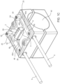
- Figure 2A is an isometric view of a first or second body 4, 5 of the clamping assembly 1.
- Figures 2B and 2C are plan views of the opposed outwardly and inwardly facing faces 10A, 10F of the first body 4 of the clamping assembly 1.
- Figures 2D and 2E are plan views of the opposed outwardly and inwardly facing faces 10A, 10F of the second body 5 of the clamping assembly 1.
- Figure 2F is an isometric view of the clamp assembly 1, including the lid 7 thereon.
- each of the first and second clamp bodies 4, 5 are generally configured as a rectangular prism with curved outer edges and flat outer surfaces, but on the inwardly or tube facing side thereof, the semi-cylindrical surface 40 extends arcuately inwardly of the first and second bodies 4, 5 from the inwardly facing surface thereof.
- the clamp body 4 has six, distinct from one another, outer surfaces, generally, generally flat or planar faces 10A-F, and semi-cylindrical surface 40 extending inwardly of face 10F.
- the top or outwardly facing face 10A is a square or rectangle in plan view and may have rounded corners, and in use of the clamp assembly 1 the outer face 10A of body 4 is covered by lid 7.
- the lid 7 fastens over the assembly to provide a moisture seal and electrical isolation.
- the second pair of fastener cavities 22, 24 may extend inwardly of the inwardly facing face 10F of the second clamp body 5, and terminate within the volume of the second clamp body 5.
- a threaded insert (not shown) is located within each of the cavities of the second pair of fastener cavities 22, 24.
- the outer perimeter of each of the first and second bodies 4, 5 includes opposed side faces 10b, 10C, extending generally parallel to one another and terminating their opposed ends at opposed end faces 10D, 10E.
- First body 4 is here configured to receive the thermal pad 3 and the bus bars 6a, 6b thereon or therein, to enable heat transfer between a thermal device 2 to be contacted with the thermal pad 3 and the outer surface and thus the wall of a pipe or tube 8 clamped or otherwise secured between the opposed semi-cylindrical surfaces 40 of the first and second clamp bodies 4, 5.
- the thermal device 2 is connected to a device located exteriorly of the clamp assembly 1 through the electrically conductive bus bars 6a, b to allow electrical signals to be transmitted to a device such as a thermal monitoring device or to allow an electrical source to input power to the thermal device 2 to cause heating or cooling thereof (not shown).
- Each rectangular recess cavity 16, 17 extends inwardly of the outwardly facing face 10A, but not through the body 4, and thus provides a recessed or inset region within which components useful for obtaining, and transmitting, for example, an electrical signal representative of the temperature of a pipe or tube 8 clamped between the first and second bodies 4,5, or useful to provide electrical power to cause the thermal device 2 to increase or decrease in temperature, and thereby transfer heat into, or remove heat from, the pipe or tube 8 through the thermal pad 3.
- the inwardly facing face 15F is a square or rectangular face with rounded corners and curved edges, and the semi-cylindrical surface 40 extends thereinto to bisect the inwardly facing face 15F.
- the second pair of fastener cavities 22, 24 extend at least inwardly of the inwardly facing face 15F.
- the cavities of the second pair of cavities 22, 24 may be threaded, such as with a threaded insert, be blind holes of a diameter whereby the fasteners will self-thread into the walls thereof, or extend through the second body 5 and open at the outwardly facing face 15A thereof, such that a threaded fastener can be secured in the cavities 22, 24 or threaded into a fastener bearing against the outwardly facing face 15a.
- fasteners having a head bearing against the outwardly facing face 10A of body 4, one of each extending through one of the first pair of cavities 13, 14 and one of the second pair of cavities 22, 24, to be threaded thereinto or into a female threaded fastener to bear against the outwardly facing face 15A of the second body 5, allow the bodies 4, 5 to be brought together to clamp a pipe or tube 8 therebetween.
- the first and second bodies 4, 5 may be held together by an exterior clamp, or be hinged together on one sidewall thereof and held together by an integral clasp member on a different sidewall thereof as show in figures 10A and 10B .
- the second clamp body 5 is configured of a low thermal conductivity plastic material such as polyethylene, polyacrylate, polyvinylchloride, ceramic or other relatively low thermal conductivity materials that can be easily machined, molded, or molded to near net shape and then machined, to yield the above-described structural elements.
- the second clamp body 5 may be made of a non-electrically insulating material such as a metal if the design warrants the clamp bodies having high thermal conductivity.
- the middle cavity 12 in the first clamp body 4 extends from an opening 42 in the outwardly facing face 10A and through the first body 4 to open through the semi-cylindrical surface 40 at opening 44.
- the cavity 12 is square or rectangular in cross-section, and the portion of the thermal pad 3 extending therethrough has the same cross section as the perimeter of the opening.
- Other opening or cavity 12 shapes, and corresponding thermal pad cross sections, such as circular, ovoid, multi-sided or other are also contemplated herein.
- the thermal pad 3 may be free to cove within the opening, may be larger in cross section than that of the cavity 12, or may be adhered to the inner wall(s) of the cavity 12 such as with epoxy or another adhesive.
- thermal pad 3 includes an enlarged tail portion 46 having a width W greater than the width w of the cavity 12, and optionally a depth, extending in the directional orthogonal to the page of Figure 5 , greater than the corresponding depth of the opening 44 extending in the directional orthogonal to the page of Figure 5 .
- a projecting portion 48 of the thermal pad 3 extends from the tail portion 46 inwardly of the cavity 12, such that a perimeter ledge 50 extends circumferentially about the location thereof where the projecting portion 48 and tail 46 meet.
- the perimeter ledge 50 supports the semi-cylindrical surface 40 facing side of the tail 46 against the inwardly facing surface of the semi cylindrical surface 40 of the first body 4 about the perimeter of the opening 42, and thus limits the position of the projecting portion 48 within the cavity 12 and prevents the tail portion 46 from being pushed through the cavity 12.
- the outer surface 54 of the projecting tail 46 portion has the same cross sectional shape as that of the a generally rectangular perimeter of the cavity 12, here four generally flat walls sized slightly larger than the flat side walls of the cavity 12, such that the projecting tail portion 46 may be easily placed into the opening, and if desired adhered to the sidewalls of the cavity 12, such as with epoxy or another adhesive.
- the projecting portion 48 may be easily placed into, and removed from, the cavity 12, i.e., not adhered to the first body 4 or the sidewalls of the cavity 12.
- a engagement face 52 of the extending portion forms the terminus of the projecting portion distal to the perimeter ledge 50.
- the engagement face 52 of the extending tail portion 46 extends as a flat planar surface outwardly of and across opposed sides of the adjacent semi-cylindrical surface 40 to either side of the cavity 12.
- the outer surface 41 of the tube 8 will bias the engagement face 52 surface inwardly toward the extending tail portion 46 to conform to the outer surface 41 of the pipe or tube 8, as shown by compressed profile 56 of the engagement face 52 as shown in Figure 5B .
- contact pressure between the surface of the compressed profile 56 of the engagement face 52 and the contacting portion of the outer surface 41 of the pipe or tube 8 is ensured, which ensures high thermal conductivity between the engagement 52 of the projecting portion 48 and the outer surface of the pipe or tube 8.
- the tail portion 46 in the compressed condition thereof of Figure 5B , where the first and second bodies 4, 5 are clamping the pipe or tube 8 therebetween, causes the outer surface 41 of the pipe or tube 8 to be spaced from the entire semi-cylindrical surface 40 of the first body 4, and spaced from substantially all of the semi-cylindrical surface 40 of the second body 5. It is contemplated herein that the contact between the second body 5, and the outer wall of the pipe or tube, can be as small as line contact therebetween, extending inwardly of the page of Figure 5B .
- Tail 46 of thermal pad 3, where here the opening 12 has a generally square or rectangular perimeter has a generally cuboid shape, having four head perimeter walls 60a-d extending generally perpendicularly away from the perimeter ledge 50 and projecting portion 48 and terminating at an upper mounting face 62 as shown in Figures 1C and 5A .
- Tail perimeter walls 60b, d are parallel to one another, have the same length in the direction parallel to the outwardly facing face 10A of the first body 4, and terminate at their opposed ends in longer perimeter walls 60a, c likewise of equal length to one another in the direction parallel to the outwardly facing face 10A.
- An element recess 58 extends inwardly of the upper mounting face 62 of the tail 46 of the thermal pad 3, generally parallel to the running direction of head perimeter walls 60a, c and it also terminates and opens into, at its opposed ends, head perimeter walls 60b, d.
- element recess 58 is configured to have the same general profile as the outer surface of a thermal device 2, which will extend partially thereinto.
- the thermal device 2 can include one or more of a temperature-measuring device, thermal fuse, thermal switch, temperature sensor, solid-state temperature sensor, thermocouple, thermostat, heating element or cooling element.
- the spanning wall 66 of the lid 7 here contacts the outer surface of the thermal device 2 to press the surface thereof opposed to the lid 7 inwardly of the element recess 58, to ensure good thermal contact therebetween.
- at least a portion of the cylindrical outer surface 64 of the thermal device 2 facing the recess 58 is adhered thereto using a thermally conductive adhesive.
- the conductive lines 9 may lead to a temperature threshold alarm, a temperature readout monitor, a controller controlling the fluid properties such as flow rate, temperature, viscosity, and heater or cooler controller or power supply where the thermal device is a heating or a cooling device, etc., or another monitoring or control element.
- each of the conductive lines 9 includes an outer insulative jacket 9a, and a central conductive core 9b.
- Jacket 9a is stripped away from the core near the terminal end of each conductive line, such that the conductive core 9b extends inwardly of a connection opening 70 in the sidewall of each of the bus bars 6a, 6b.
- the second end 32 of the bus bar 6 has an upper protrusion or lip 33 into which a wire receiving opening 31 extends, and a threaded opening into which the first conductive fastener 20 is threaded.
- the base of the shaft of the first conductive fastener 20 face the lower portion of the wire-receiving opening.
- the end of the conductive wires 25, 25', first conductive wire 25 shown, extends inwardly of the wire receiving opening 31.
- the thermal device 2 can include one or more of a temperature-measuring device, thermal fuse, thermal switch, temperature sensor, solid-state temperature sensor, thermocouple, thermostat or other thermally sensitive element or a heat generating, or a heat sinking (cooling) element.
- the clamp assembly 1 can thus be configured, along with an external monitoring circuit, to act as a high- or low-temperature alarm, cutoff, or real-time measuring or monitoring device for an outer wall of a pipe or tube 8, and the monitored or measured value of the wall temperature used to control or shut off an equipment (not shown) to which, from which, or within which fluid in the pipe or tube 8 monitored by the clamping assembly is flowing or present.
- the measured or monitored temperature can be used to interrupt the power supplied to the equipment for safety or performance reasons, or to control a thermal fluid circuit associated with the equipment to maintain the wall temperature within a range indicative of a desired temperature of the fluid in the pipe or tube 8.
- the thermal device 2 may be configured to transmit data received or generated therein indicative of the temperature of the wall of the tubing 8 wirelessly. In which case the bus bars 6a, b are unnecessary.
- the conductive lines 9, 9' can be connected to a wireless transmitter to transmit data regarding the wall temperature of the pipe or tube 8 to a control device for an equipment.
- the data output from the thermal device may be recorded or logged to monitor the thermal conditions of the outer wall of the pipe or tube 8, the electrical conditions of the thermal device, or both.
- the conductive wires 25, 25' extend from the thermal device on opposed ends or sides thereof.
- the thermal device 2 can be configured as a heating or cooling device, whereby heat transfer occurs through the thermal pad 3 to transfer heat from the pipe or tube 8 to the thermal device 2, or to transfer heat from the thermal device 2 to the pipe or tube 8.
- the thermal device 2 can be grounded to, or ungrounded from, the clamping assembly 1, depending on the use or requirements of the thermal device 2. If the thermal device 2 is to be grounded to the clamping assembly, at least one of the first and second bodies 4, 5 need be conductive and connected through a ground strap to ground, where the thermal device is electrically connected to the grounded body, or be conductive where the pipe or tube 8 is grounded and contact between at least the second clamp body 5 on the wall of the pipe or tube 8 be of sufficient quality to provide an electrically conductive path therebetween, or be insulative and a ground strap provided to ground to which the thermal device 2 can be electrically connected.
- fasteners herein bolts 74 having a machine screw thread, extend through first body 4 and are received within threaded cavities 22, 24 in the second body 5, or extend through unthreaded versions of the cavities 22, 24 extending fully through the second body 5.
- the bolts 74 can be configured with self- tapping threads, wherein they will form threads in the cavities 22, 24 when turned thereinto to secure the first and second bodies 4, 5 together.
- Each bolt 74 has an enlarged bolt head 76 and long, thinner threaded shaft 78. The bottom or underside of the bolt head 76 rests or bears on a recess surface on the outwardly facing face 10A of the first body.
- the cavities 22, 24 may include a threaded insert therein, into which the shafts 78 of the bolts 74 are threaded to pull and secure the first and second bodies 4, 5 together, or the cavities 22, 24 may extend through the second body, and open into the outwardly facing face 15A thereof, wherein a threaded fastener such as a nut located over a lock washer is threaded over the end of the shaft 78 and tightened to pull the first and second bodies 4, 5 together.
- a threaded fastener such as a nut located over a lock washer is threaded over the end of the shaft 78 and tightened to pull the first and second bodies 4, 5 together.
- first and second clamp bodies 4, 5 are shown disposed over and around a tubing 8 and interconnected by fasteners such as the bolt 74 threaded into a threaded insert (not shown) in the cavities 22, 24 of the second clamp body 5.
- fasteners such as the bolt 74 threaded into a threaded insert (not shown) in the cavities 22, 24 of the second clamp body 5.
- Other connecting paradigms for example clamps, may be employed to hold the first and second clamp bodies together over tube 8.
- Engagement face 52 of projecting portion 48 of the thermal pad 3 is deformed to follow the outer circumference or contour of the tube 8 against which it is biased.
- the portion of the thermal pad 3 adjacent to the engagement face 52 is conformable or deformable to match the contour of the wall of the element clamped between first and second clamp bodies 4, 5, and when the thermal pad 3 is no longer contacting the wall of an element clamped between first and second clamp bodies 4, 5, is self-restoring to its non-deformed or non-conformed contour.
- the engagement face 52 and outer surface 41 of the pipe or tube 8 can be adhered to one another using a conductive adhesive.
- the clamping assembly 1 is here configured to enable physical, by contact, connection of the engagement face 52 of the heat transfer thermal pad 3 to the outer surface 41 of a piping or tubing 8.
- the clamping assembly 1 can be used to perform automated temperature testing of a piping or tubing 8, and therein be configured to be connected to a temperature read out monitor or a temperature threshold alarm.
- temperature testing of the different areas of a piping/tubing 8 or different pipes or tubes 8 may be performed by detachment and reattachment of the clamp assembly 1 on different segments of pipes or tubes 8 for which the temperature is of interest, such as an area of a tube 8 known to flow extremely hot or cold fluids.
- the clamp assembly 1 When in use, the clamp assembly 1 is comprised of the first clamp body 4, the second clamp body 5, the heat transfer thermal pad 3, and the bus bar 6, and optionally the lid 7.
- the thermal device 2 is received therein, in contact with the thermal pad 3.
- One function of the clamping assembly 1 is to transfer heat between a measured surface such as a wall of a pipe or tube 8 and the thermal device 2 and thus correlate or measure the temperature (hot or cold) of the outer surface 41 for analytic or safety purposes.
- the thermal device 2 is one of a heater or a cooling device
- the thermal device 2 can be used to raise or lower the temperatures of the wall of the pipe or tube 8, and thus at least locally change the temperature of a fluid therein.
- the first clamp body 4 of the clamping assembly 1 serves two purposes.
- the first clamp body 4 acts a portion of the clamping mechanism extending around the measured tubing/piping 8 and in one aspect, via the thermal pad 3, thermally connects the thermal device 2 with the clamped member wall and also provides the electrical connections between the thermal device 2 to the conductive lines 9.
- the first clamp body 4 is made of an electrically non-conductive material and thermally low-conductivity material.
- the first clamp body 4 can either conform to the measured tubing/piping 8 for more surface area clamping or include a portion offset from the semi-cylindrical surface 40 to reduce heat transfer away from the thermal device 2 and into the clamp (called thermal shunting) with as little contact as line contact between the clamped member and the second clamp body 5, and only contact with the thermal pad 3 and not the remainder of the first clamp body 4.
- the first body 4 and the thermal pad 3 may be configured as a single integral member, having sufficient conformability to conform to the outer surface of an element clamped therein.
- the second clamp body 5 can be optimized for strength, cost, thermal performance, or to prevent physical interference from external components. This can be accomplished via design and/or material selection.
- the second clamp body 5 has minimal contact points and/or low heat transfer or thermal conductivity properties through selection of low heat transfer or thermal conductivity materials such as ceramics or plastics. If strength is a priority, selection of low thermally conductivity materials such as filled plastic is contemplated.
- the semi-cylindrical surface 40 of the second clamp body 5 is sized, with respect to the pipe or tube 8 outer circumference, to minimize the contact area therebetween and thus minimize the thermal coupling between the second clamp body 5 and the semi-cylindrical surface 40 of the pipe or tube.
- first and second alternative clamp bodies 4", 5" are generally configured as an oblong or egg shaped prism with curved outer edges and flat outer surfaces, but on the inwardly or tube facing side thereof, the semi-cylindrical surface 40 extends arcuately inwardly of the first and second alternative clamp bodies 4", 5" from the inwardly facing surface thereof, i.e., from the surface of each clamp body 4", 5" facing the other one of the clamp bodies 4", 5".
- the flexible web hinge comprised of the clamp body material, but is thin enough to be flexible but study enough to provide clamping force.
- the flexible web hinge 250 is molded to or epoxied to the inwardly facing face 10F of the first clamp body 4 and is molded to or epoxied to the inwardly facing face 15F of the second clamp body 5.
- the clamping assemblies 100 are here configured to enable physical contact of the engagement face 52 of the heat transfer thermal pad 3, and a portion of the semi-cylindrical surface 40 of the second body 5 to a piping or tubing 8.
- a clasp is provided to hold the first and second bodies 4, 5 together along the faces 10C, 15C thereof.
- the wire guides 240a, 240b are generally each a rectangular prism shape with 6 faces; two square walls 143, 144, an outwardly facing face 145, an inwardly facing face epoxied to the outwardly facing face 10A of the first clamp body 4, and a first and second oblong region 141, 142 with a circular prismatic hole 149 in the center of the first and second oblong regions 141, 142 and extending therethrough.
- the wire guides 240a, 240b are configured of an electrically conductive material.
- the first wire guide 240a is configured to electrically and physically connect to the first conductive wire 125.
- the first wire guide 250a receives therein the first conductive wire 125 which is crimped therein using a first conductive fastener 29a in electrical contact with the first wire guide 240a, and a first conductive line 134 which is crimped therein using a second conductive fastener 29b electrically connected therein.
- the first thermal device conductive line 134 extends from the first wire guide 240a to a thermal device 2' resting in the recess of the heat transfer thermal pad 3' as described previously.
- a second conductive line 130 extends from the opposite end of the thermal device 2' to the second wire guide 240b which is crimped therein using a third conductive fastener 29c.
- each of the conductive wires 125', 126' includes an outer insulative jacket 125a, 126a and a central conductive core 125b, 126b.
- Jacket 125a is stripped away from the core near the terminal end of each conductive wire such that the conductive core 125b, 126b extends inwardly of a connection point with the first or second conductive line 130',134' of the thermal device 2'.
- the thermal device resting in the recess of the heat transfer thermal pad 3' as described previously.
- the thermal pad 3" here extends the entire width and length of the outwardly facing face 165A of the body lid piece 140.
Landscapes
- Physics & Mathematics (AREA)
- General Physics & Mathematics (AREA)
- Thermal Insulation (AREA)
- Measuring Temperature Or Quantity Of Heat (AREA)
- Cooling Or The Like Of Electrical Apparatus (AREA)
Description
- Embodiments of the present invention generally relate to an apparatus and method for sensing the temperature of a tubing, or pipe, wall, and inferentially the temperature of a fluid within the tube or pipe. More particularly, the present invention relates to apparatus, and methods of use of the apparatus, where the apparatus is releasably connected to a tube or pipe and configured to sense the temperature of a pipe or tube wall, and inferentially the temperature of a fluid within the pipe or tube, or the temperature of an element on the exterior or interior wall of the pipe or tube wall.
- Currently, there are few robust solutions for measuring the temperature of the outer wall of a tube or pipe. One known methodology for doing so uses a clip-on device, which snaps or clips over the tube or pipe. These devices have an issue of low clamping force to the tube or pipe and low accuracy due to poor heat transfer between tube or pipe outer wall and the temperature-sensing element of the clip. Other implementations that clamp a heat sensitive element to a tube or pipe have at least one issue of difficult installation or low temperature sensitivity, for example poor temperature measurement accuracy due to poor heat transfer and their large size, as well as thermal losses to the fluid or element, the temperature of which is being measured, the thermal losses induced by the heat sensitive element. Technical solutions involving the use of two clamp bodies for clamping a pipe or tube for temperature monitoring purpose are known e.g. from
DE 10 2012 108388 A1 ,US 2020/096397 A1 , andUS 2017/284870 A1 . - Provided herein is an apparatus according to
claim 1 and a method according to claim 10 for sensing the temperature of a tubing wall, and inferentially the temperature of a fluid within the tubing. - So that the manner in which the above-recited features of the present disclosure can be understood in detail, a more particular description of the disclosure, briefly summarized above, may be had by reference to embodiments, some of which are illustrated in the appended drawings.
- Figures a 1A-C are isometric views of a clamping assembly for mounting a temperature sensitive element into thermal communication with the outer wall of a tubing or piping.
-
Figures 2A-F are isometric views of the clamping assembly for mounting a temperature sensitive element into thermal communication with the outer wall of a tubing or piping, including separate views of the individual clamp bodies thereof. -
Figure 3 is an isometric view, partially in phantom, showing the connection of the temperature sensitive element to one of the bodies of the clamping assembly and to the internal components thereof. -
Figure 4 is a side view of a clamping assembly with a tubing secured therein. -
Figures 5A and 5B are sectional view of the clamping assembly with and without a tubing fastened inside. -
Figure 6 is a sectional view of an insulator bar shown inFigure 3 , showing the internal electrical routings thereof. -
Figure 7 is a sectional side view of a portion of a clamp body of the clamp assembly thereof, including a thermal pad extending on, and into, the clamp body and a thermal device contacting the thermal pad. -
Figure 8 is an isometric view of a further alternative clamp assembly. -
Figure 9 is an isometric view of a further additional alternative clamp assembly. -
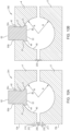
Figure 10A is a sectional view of the clamp assembly ofFigures 1A to 1C , modified to include a pin hinge connected to adjacent sidewalls of the clamp bodied thereof. -
Figure 10B is a sectional view of the clamp assembly ofFigures 1A to 1C , modified to include a web hinge connected to adjacent sidewalls of the clamp bodied thereof. -
Figure 11 is an isometric view of a modified clamp assembly with the lid removed, showing details of modifications to the thermal coupling and electrical connections of the first body thereof. -
Figure 12A is a top view of a body lid for a clamp assembly. -
Figure 12B is a bottom view of the body lid offigure 12A . -
Figure 12C is an isometric view of the body lid ofFigures 12A and12B . -
Figure 12D is a side view of the body lid ofFigures 12A ,12B and 12C . - To facilitate understanding, identical reference numerals have been used, where possible, to designate identical elements that are common to the figures. It is contemplated that elements and features of one embodiment may be beneficially incorporated in other embodiments without further recitation.
- Provided herein is a temperature sensing or heat generating device configured as a
clamp assembly 1. In one aspect thereof, theclamp assembly 1 is configured of opposed first and second halves orbodies second bodies tube 8 using fasteners such as bolts or clips or other attachment elements to secure the pipe or tube therebetween. Athermal device 2 configured as a temperature monitoring or measuring device, or as a heat generating or receiving device, is receivable on one of the bodies, herefirst body 4, which here is configured to allow thethermal device 2, for example a temperature sensing element, to be mounted thereto to sense the temperature of the exterior wall of atube 8 over which theclamp assembly 1 is clamped. Here, thethermal device 2 can be configured as one or more of a temperature measuring element useful in a temperature monitoring circuit, a thermal fuse, a thermal alarm device, or other element which senses temperature of an element, here of the outer wall of thetube 8 at least inferentially, or a heat generating or absorbing element to locally absorb heat from, or direct heat into, the outer wall of thetube 8. This heat absorbing or generating element can at least locally change the temperature of a fluid present in thetube 8, including a fluid flowing therein, or heat or cool another material locally within or on thetube 8. - The
clamp assembly 1 is configured to provide a heat transfer path between the outer surface of a pipe ortube 8 and thethermal device 2 carried on a portion of one of the bodies, here afirst body 4, of theclamp assembly 1. In the aspect hereof shown inFigures 1a-1c ,clamp assembly 1 includes the first andsecond clamp bodies first clamp body 4 not present or not needed insecond clamp body 5. However, each of theclamp bodies thermal device 2 and thetube 8, and the elements used to control or monitor thethermal device 2, which are mounted on or into thefirst clamp body 4, will not need to be present in or on thesecond clamp body 5. Here, each offirst clamp body 4 and asecond clamp body 5 include two fastener cavities, here a first pair offastener cavities 13, 14 (first clamp body 4,Figure 2B ) and a second pair offastener cavities 22, 24 (second clamp body 5,Figure 2D ), and anarched recess 11, here, a semicircular recess 11A having asemi-cylindrical surface 40 of radius R (Figure 5A ) extending inwardly of thetube 8 facing side, i.e., the inwardly facingface 10F of the first andsecond bodies opposed end faces first body 4 includes a heat transferthermal pad 3 connected to thefirst body 4 and extending therethrough (Figures 5A, 5B ) and configured for the receipt of thethermal device 2 thereagainst, and a pair ofbus bars 6a, b provided to electrically interconnect thethermal device 2 to a device located exteriorly of theclamp assembly 1. Alid 7 extends over the outwardly facingface 10A of the first body 4 (Figures 1A, 1B ), and over thebus bars 6a, b andthermal pad 3 thereon or therein located as shown inFigure 1C . Here, thelid 7 is affixed to thefirst body 4 using an adhesive. The primary function of theclamping assembly 1 is to establish heat transfer between a surface of the pipe ortube 8 and thethermal device 2 held therein or thereon, through thethermal pad 3. Thus, where thethermal device 2 is a temperature-sensing element, the thermal device can accurately detect or infer the temperature of the outer wall of the pipe ortube 8. Similarly, if thethermal device 2 is configured to locally heat or cool the outer surface of the pipe ortube 8, thethermal pad 3 thermally couples thethermal device 2 to the outer surface of the pipe ortube 8, enabling control of the heat transfer into, or from, the wall of the pipe ortube 8 through thethermal pad 3. Thus, the heat transferringthermal pad 3 andfirst body 4 are together configured to allow thethermal pad 3 to extend through thefirst body 4 and outwardly of the semi-cylindricalinner surface 40 thereof (i.e., extend from the semi-cylindricalinner surface 40 ofbody 4 and toward the center of the radius along which thesemi-cylindrical surface 40 extends As shown inFigure 5A ), as well as above the opposed outwardly facingface 10A of thefirst body 4 over which thelid 7 is positioned (Figure 1C ) As a result, athermal device 2 can be in contact with the portion of thethermal pad 3 extending above the upper surface of thefirst body 4, whilst the portion of thethermal pad 3 extending through thefirst body 4 will contact the outer surface of atube 8 clamped between the first andsecond bodies -
Figure 2A is an isometric view of a first orsecond body clamping assembly 1.Figures 2B and 2C are plan views of the opposed outwardly and inwardly facingfaces first body 4 of theclamping assembly 1.Figures 2D and 2E are plan views of the opposed outwardly and inwardly facingfaces second body 5 of theclamping assembly 1.Figure 2F is an isometric view of theclamp assembly 1, including thelid 7 thereon. In this embodiment, each of the first andsecond clamp bodies semi-cylindrical surface 40 extends arcuately inwardly of the first andsecond bodies clamp body 4 has six, distinct from one another, outer surfaces, generally, generally flat orplanar faces 10A-F, andsemi-cylindrical surface 40 extending inwardly offace 10F. The top or outwardly facingface 10A is a square or rectangle in plan view and may have rounded corners, and in use of theclamp assembly 1 theouter face 10A ofbody 4 is covered bylid 7. Thelid 7 fastens over the assembly to provide a moisture seal and electrical isolation. - Referring again to
Figures 1 to 6 , on the opposite side of thebody 4 from the outwardly facingface 10A is the inwardly facingface 10F, again a generally planar surface, which is bisected by the recess formed of the inwardly thereof extendingsemi-cylindrical surface 40. The first pair offastener cavities body 4, and the second pair offastener cavities face 10F of thesecond body 5, and each opens through the outwardly facingface 10A and the inwardly facingface 10F of first andsecond bodies semi-cylindrical surface 40. Alternatively, the second pair offastener cavities face 10F of thesecond clamp body 5, and terminate within the volume of thesecond clamp body 5. In this case, if the material of thesecond clamp body 5 has limited yield strength, a threaded insert (not shown) is located within each of the cavities of the second pair offastener cavities second bodies opposed side faces opposed end faces Semi-cylindrical surface 40, at its opposed ends in the non-circumferential direction thereof, terminates atend faces face 10A and inwardly facingface 10F likewise terminate, at opposed ends thereof in a first direction, atend faces -
First body 4 is here configured to receive thethermal pad 3 and thebus bars thermal device 2 to be contacted with thethermal pad 3 and the outer surface and thus the wall of a pipe ortube 8 clamped or otherwise secured between the opposedsemi-cylindrical surfaces 40 of the first andsecond clamp bodies thermal device 2 is connected to a device located exteriorly of theclamp assembly 1 through the electricallyconductive bus bars 6a, b to allow electrical signals to be transmitted to a device such as a thermal monitoring device or to allow an electrical source to input power to thethermal device 2 to cause heating or cooling thereof (not shown). - Here,
first body 4 includes three cavities extending inwardly of outwardly facingface 10A, amiddle cavity 12 flanked by tworectangular recess cavities middle cavity 12. Therectangular recess cavities face 10A and generally parallel to the surface direction of end faces 10D and 10E, i.e., in the direction extending between end faces 10D, 10E. Themiddle cavity 12 is generally centered on the outwardly facingface 10A with respect to the edges of outwardly facingface 10A, and is an opening here having a square or rectangular perimeter wall extending through thebody 4 from the outwardly facingface 10A thereof to, and opening through, thesemi-cylindrical surface 40 thereof.Middle cavity 12 is configured to allow a thermal transfer element, here a portion of thethermal pad 3, to extend therethrough and also extend beyond thesemi-cylindrical surface 40 and the outwardly facingface 10A of thebody 4. Thus, when the twobodies clamp assembly 1 are secured together, the portion of thethermal pad 3 extending beyond thesemi-cylindrical surface 40 contacts the outer surface of a pipe ortube 8 extending within a circumferential boundary defined by the facingsemi-cylindrical surfaces 40 of both of the first andsecond bodies middle cavity 12, between themiddle cavity 12 and end faces 10D and 10E ofbody 4, lie the tworectangular recess cavities rectangular recess cavity face 10A, but not through thebody 4, and thus provides a recessed or inset region within which components useful for obtaining, and transmitting, for example, an electrical signal representative of the temperature of a pipe ortube 8 clamped between the first andsecond bodies thermal device 2 to increase or decrease in temperature, and thereby transfer heat into, or remove heat from, the pipe ortube 8 through thethermal pad 3. - Each side face, 10B and 10C is a rectangular face with curved edges and rounded corners. The opposed end faces, 10D and 10E respectively, are rectangular faces with curved edges and rounded corners and an arched recess forming the edge thereof where
semi-cylindrical surface 40 meets theend face first clamp body 4 is configured of a low thermal conductivity plastic material such as polyethylene, polyacrylate, polyvinylchloride, polycarbonate, ABS, or other relatively low thermal conductivity materials that can be easily machined, molded, or molded to near net shape and then machined, to yield the above-described structural elements. Alternatively, in other applications, theclamp bodies thermal pad 3 can be configured as an integral extension of one of the bodies. - The
second clamp body 5 is likewise generally a rectangular prism with curved outer edges. Thesecond clamp body 5 also has the six, distinct from one another, outer surfaces, generally faces 10A-F andsemi-cylindrical surface 40. The outwardly facingface 15A is a square or rectangular surface with rounded corners. Each side face, 15B and 15C is a rectangular surface with curved edges and rounded corners. The opposed end faces, 15D and 15E respectively, are rectangular surfaces with curved edges and rounded corners and an arched recess edge where thesemi-cylindrical surface 40 meets the end faces 15d, 15E. The inwardly facingface 15F is a square or rectangular face with rounded corners and curved edges, and thesemi-cylindrical surface 40 extends thereinto to bisect the inwardly facingface 15F. The second pair offastener cavities face 15F. The cavities of the second pair ofcavities second body 5 and open at the outwardly facingface 15A thereof, such that a threaded fastener can be secured in thecavities face 10A ofbody 4, one of each extending through one of the first pair ofcavities cavities face 15A of thesecond body 5, allow thebodies tube 8 therebetween. Alternatively, the first andsecond bodies figures 10A and 10B . Like thefirst body 4, thesecond clamp body 5 is configured of a low thermal conductivity plastic material such as polyethylene, polyacrylate, polyvinylchloride, ceramic or other relatively low thermal conductivity materials that can be easily machined, molded, or molded to near net shape and then machined, to yield the above-described structural elements. In another embodiment, thesecond clamp body 5 may be made of a non-electrically insulating material such as a metal if the design warrants the clamp bodies having high thermal conductivity. - As shown in
Figures 5A and 5B , themiddle cavity 12 in thefirst clamp body 4 extends from anopening 42 in the outwardly facingface 10A and through thefirst body 4 to open through thesemi-cylindrical surface 40 atopening 44. In one aspect, thecavity 12 is square or rectangular in cross-section, and the portion of thethermal pad 3 extending therethrough has the same cross section as the perimeter of the opening. Other opening orcavity 12 shapes, and corresponding thermal pad cross sections, such as circular, ovoid, multi-sided or other are also contemplated herein. Thethermal pad 3 may be free to cove within the opening, may be larger in cross section than that of thecavity 12, or may be adhered to the inner wall(s) of thecavity 12 such as with epoxy or another adhesive. Here,thermal pad 3 includes anenlarged tail portion 46 having a width W greater than the width w of thecavity 12, and optionally a depth, extending in the directional orthogonal to the page ofFigure 5 , greater than the corresponding depth of theopening 44 extending in the directional orthogonal to the page ofFigure 5 . A projectingportion 48 of thethermal pad 3 extends from thetail portion 46 inwardly of thecavity 12, such that aperimeter ledge 50 extends circumferentially about the location thereof where the projectingportion 48 andtail 46 meet. Theperimeter ledge 50 supports thesemi-cylindrical surface 40 facing side of thetail 46 against the inwardly facing surface of the semicylindrical surface 40 of thefirst body 4 about the perimeter of theopening 42, and thus limits the position of the projectingportion 48 within thecavity 12 and prevents thetail portion 46 from being pushed through thecavity 12. Here, theouter surface 54 of the projectingtail 46 portion has the same cross sectional shape as that of the a generally rectangular perimeter of thecavity 12, here four generally flat walls sized slightly larger than the flat side walls of thecavity 12, such that the projectingtail portion 46 may be easily placed into the opening, and if desired adhered to the sidewalls of thecavity 12, such as with epoxy or another adhesive. In another embodiment, the projectingportion 48 may be easily placed into, and removed from, thecavity 12, i.e., not adhered to thefirst body 4 or the sidewalls of thecavity 12. - A
engagement face 52 of the extending portion forms the terminus of the projecting portion distal to theperimeter ledge 50. In its free state, i.e., where it is not compressed or biased in the direction of thesemi-cylindrical surface 40 or thecavity 12, theengagement face 52 of the extendingtail portion 46 extends as a flat planar surface outwardly of and across opposed sides of the adjacentsemi-cylindrical surface 40 to either side of thecavity 12. As a result, when atube 8 is received within the perimeter of thesemi-cylindrical surfaces 40 of, and clamped between, the first andsecond bodies outer surface 41 of thetube 8 will contact theengagement face 52. As the first andsecond bodies outer surface 41 of thetube 8 will bias theengagement face 52 surface inwardly toward the extendingtail portion 46 to conform to theouter surface 41 of the pipe ortube 8, as shown by compressed profile 56 of theengagement face 52 as shown inFigure 5B . As a result, contact pressure between the surface of the compressed profile 56 of theengagement face 52 and the contacting portion of theouter surface 41 of the pipe ortube 8 is ensured, which ensures high thermal conductivity between theengagement 52 of the projectingportion 48 and the outer surface of the pipe ortube 8. Additionally, thetail portion 46, in the compressed condition thereof ofFigure 5B , where the first andsecond bodies tube 8 therebetween, causes theouter surface 41 of the pipe ortube 8 to be spaced from the entiresemi-cylindrical surface 40 of thefirst body 4, and spaced from substantially all of thesemi-cylindrical surface 40 of thesecond body 5. It is contemplated herein that the contact between thesecond body 5, and the outer wall of the pipe or tube, can be as small as line contact therebetween, extending inwardly of the page ofFigure 5B . As a result, changes in the temperature of theouter surface 41 of the pipe ortube 8 caused by heat transfer thereinto or therefrom through the first and second bodies, as well as thermal hysteresis effects, which would occur where the second body forms a heat sink for thesecond body 5, are minimized. -
Tail 46 ofthermal pad 3, where here theopening 12 has a generally square or rectangular perimeter, has a generally cuboid shape, having fourhead perimeter walls 60a-d extending generally perpendicularly away from theperimeter ledge 50 and projectingportion 48 and terminating at an upper mountingface 62 as shown inFigures 1C and5A .Tail perimeter walls 60b, d are parallel to one another, have the same length in the direction parallel to the outwardly facingface 10A of thefirst body 4, and terminate at their opposed ends inlonger perimeter walls 60a, c likewise of equal length to one another in the direction parallel to the outwardly facingface 10A. Anelement recess 58 extends inwardly of the upper mountingface 62 of thetail 46 of thethermal pad 3, generally parallel to the running direction ofhead perimeter walls 60a, c and it also terminates and opens into, at its opposed ends,head perimeter walls 60b, d. - Referring to
Figures 1C , and3 ,element recess 58 is configured to have the same general profile as the outer surface of athermal device 2, which will extend partially thereinto. For example, here, where the temperature sensing element has a right cylindrical outer surface 64 (Figure 6 ), therecess 58 likewise has a generally semi-cylindrical profile, i.e., the ends thereof opening intohead perimeter walls 60b, d are semicircles or within a few degrees of being semicircles. Here, thethermal device 2 can include one or more of a temperature-measuring device, thermal fuse, thermal switch, temperature sensor, solid-state temperature sensor, thermocouple, thermostat, heating element or cooling element. In one aspect, the spanningwall 66 of thelid 7 here contacts the outer surface of thethermal device 2 to press the surface thereof opposed to thelid 7 inwardly of theelement recess 58, to ensure good thermal contact therebetween. In another aspect, at least a portion of the cylindricalouter surface 64 of thethermal device 2 facing therecess 58 is adhered thereto using a thermally conductive adhesive. - As previously described and as shown in
Figures 2B and3 , two oblong, here rectangular,recess cavities face 10A offirst body 4, one to each side of themiddle cavity 12 on the opposed sides thereof not containingfastener cavities recess cavity 16 is located betweenmiddle cavity 12 and side face 10E, andrecess cavity 17 is located betweenmiddle cavity 12 andside face 10D. Therectangular recess cavities first clamp body 4 from the outwardly facingface 10A thereof but not through to thesemi-circumferential surface 40 thereof. Here, thethermal device 2 includes a pair ofconductive wires 25, 25' extending therefrom. Therectangular recess cavities second bus bar bus bar 6a, b is conductive and is configured to electrically interconnect theconductive wires 25, 25' withcorresponding conducting lines 9, 9' associated therewith As shown inFigure 6 , eachbus bar 6a, b here has the same construction and are interchangeable, and each receives therein one of theconductive wires 25, 25', which is crimped or clamped therein to electrically connect theconductive wire 25 or 25' thereto using a firstconductive fastener 20 in physical and electrical contact with abus bar 6a, b, and aconductive line 9, 9' which is crimped or clamped therein using a secondconductive fastener 26 physically and electrically connected to abus bar 6a, b, to electrically connect thethermal device 2 to the exterior of theclamp assembly 1 through theconductive lines 9, 9'. Theconductive lines 9 may lead to a temperature threshold alarm, a temperature readout monitor, a controller controlling the fluid properties such as flow rate, temperature, viscosity, and heater or cooler controller or power supply where the thermal device is a heating or a cooling device, etc., or another monitoring or control element. - The
conductive lines 9 , 9' each extend into correspondingopenings 72, 72' extending inwardly of one of the end faces 10B and 10C of thefirst clamp body 4, here face 10B, and into a corresponding one of therecess cavities Figure 6 , which is a sectional view of thebus bars 6a, b, each of theconductive lines 9 includes anouter insulative jacket 9a, and a centralconductive core 9b.Jacket 9a is stripped away from the core near the terminal end of each conductive line, such that theconductive core 9b extends inwardly of aconnection opening 70 in the sidewall of each of thebus bars conductive fastener 26, for example a machine screw also in contact withconductive bus bar conductive core 9b of each conductive line between the surface of the secondconductive fastener 26 and the inner surface of theconnection opening 70. Eachbus bar conductive core 9b of theconductive lines 9, 9'. The bus bars 6a and 6b extend longitudinally from thefirst end 30 of thebus bar 6 to a location inwardly of the second end 32 thereof, wherein thebus bar 6 contacts the firstconductive fastener 20, for example a machine screw, comprising a conductive material. The second end 32 of thebus bar 6 has an upper protrusion orlip 33 into which a wire receiving opening 31 extends, and a threaded opening into which the firstconductive fastener 20 is threaded. The base of the shaft of the firstconductive fastener 20 face the lower portion of the wire-receiving opening. The end of theconductive wires 25, 25', firstconductive wire 25 shown, extends inwardly of the wire receiving opening 31. By threading the firstconductive fastener 20 inwardly of the upper lip, the base of the shaft thereof biases a portion of the firstconductive wire 25 against the wall of the wire receiving opening 31, thus electrically connecting theconductive wire 25 to the exterior of theclamp assembly 1 through thebus bars 6a, b and the exteriorly extendingconductive line 9. Similarly, the second conductive wire 25' is electrically connected through thesecond bus bar 6b to an exterior conductive line 9', to connect the first and secondconductive wires 25, 25' to a component external to the clamp assembly. - As discussed previously herein, the
thermal device 2 can include one or more of a temperature-measuring device, thermal fuse, thermal switch, temperature sensor, solid-state temperature sensor, thermocouple, thermostat or other thermally sensitive element or a heat generating, or a heat sinking (cooling) element. Theclamp assembly 1 can thus be configured, along with an external monitoring circuit, to act as a high- or low-temperature alarm, cutoff, or real-time measuring or monitoring device for an outer wall of a pipe ortube 8, and the monitored or measured value of the wall temperature used to control or shut off an equipment (not shown) to which, from which, or within which fluid in the pipe ortube 8 monitored by the clamping assembly is flowing or present. For example, where theouter surface 41 temperature of the pipe ortube 8 desirably operates in a specific temperature range, the measured or monitored temperature can be used to interrupt the power supplied to the equipment for safety or performance reasons, or to control a thermal fluid circuit associated with the equipment to maintain the wall temperature within a range indicative of a desired temperature of the fluid in the pipe ortube 8. Additionally, thethermal device 2 may be configured to transmit data received or generated therein indicative of the temperature of the wall of thetubing 8 wirelessly. In which case thebus bars 6a, b are unnecessary. Additionally, theconductive lines 9, 9' can be connected to a wireless transmitter to transmit data regarding the wall temperature of the pipe ortube 8 to a control device for an equipment. Likewise, the data output from the thermal device may be recorded or logged to monitor the thermal conditions of the outer wall of the pipe ortube 8, the electrical conditions of the thermal device, or both. Here, theconductive wires 25, 25' extend from the thermal device on opposed ends or sides thereof. However, other configurations, for example where the conductors in the form ofconductive wires 25, 25' extend from the same side or end of thethermal device 2, are also contemplated. Additionally, thethermal device 2 can be configured as a heating or cooling device, whereby heat transfer occurs through thethermal pad 3 to transfer heat from the pipe ortube 8 to thethermal device 2, or to transfer heat from thethermal device 2 to the pipe ortube 8. Thethermal device 2 can be grounded to, or ungrounded from, the clampingassembly 1, depending on the use or requirements of thethermal device 2. If thethermal device 2 is to be grounded to the clamping assembly, at least one of the first andsecond bodies tube 8 is grounded and contact between at least thesecond clamp body 5 on the wall of the pipe ortube 8 be of sufficient quality to provide an electrically conductive path therebetween, or be insulative and a ground strap provided to ground to which thethermal device 2 can be electrically connected. - As shown in
Figures 2D and3 , to fasten together thefirst body 4 andsecond body 5, fasteners, hereinbolts 74 having a machine screw thread, extend throughfirst body 4 and are received within threadedcavities second body 5, or extend through unthreaded versions of thecavities second body 5. Additionally, thebolts 74 can be configured with self- tapping threads, wherein they will form threads in thecavities second bodies bolt 74 has anenlarged bolt head 76 and long, thinner threadedshaft 78. The bottom or underside of thebolt head 76 rests or bears on a recess surface on the outwardly facingface 10A of the first body. Thebolt shafts 78 extend through thecavities face 10A, through thefirst clamp body 4, and outwardly of the inwardly facingface 10F offirst body 4. Threadedwashers 19 are connected to thebolt shafts 78 adjacent the inwardly facingface 10F of thefirst body 4 to retain thebolts 74 thereon. Abolt 74 extends through eachcavity first clamp body 4. Here, the end of theshaft 78 of thebolt 74 extends into thecavities second clamp body 5 and opening into inwardly facingface 15F of thesecond clamp body 5. Thecavities shafts 78 of thebolts 74 are threaded to pull and secure the first andsecond bodies cavities face 15A thereof, wherein a threaded fastener such as a nut located over a lock washer is threaded over the end of theshaft 78 and tightened to pull the first andsecond bodies - In
Figures 5A and 5B the first andsecond clamp bodies tubing 8 and interconnected by fasteners such as thebolt 74 threaded into a threaded insert (not shown) in thecavities second clamp body 5. Other connecting paradigms, for example clamps, may be employed to hold the first and second clamp bodies together overtube 8.Engagement face 52 of projectingportion 48 of thethermal pad 3 is deformed to follow the outer circumference or contour of thetube 8 against which it is biased. Here, at least the portion of thethermal pad 3 adjacent to theengagement face 52 is conformable or deformable to match the contour of the wall of the element clamped between first andsecond clamp bodies thermal pad 3 is no longer contacting the wall of an element clamped between first andsecond clamp bodies engagement face 52 andouter surface 41 of the pipe ortube 8 can be adhered to one another using a conductive adhesive. - Referring to
Figure 5 , the clampingassembly 1 is here configured to enable physical, by contact, connection of theengagement face 52 of the heat transferthermal pad 3 to theouter surface 41 of a piping ortubing 8. For example, the clampingassembly 1 can be used to perform automated temperature testing of a piping ortubing 8, and therein be configured to be connected to a temperature read out monitor or a temperature threshold alarm. Additionally, temperature testing of the different areas of a piping/tubing 8 or different pipes ortubes 8 may be performed by detachment and reattachment of theclamp assembly 1 on different segments of pipes ortubes 8 for which the temperature is of interest, such as an area of atube 8 known to flow extremely hot or cold fluids. When in use, theclamp assembly 1 is comprised of thefirst clamp body 4, thesecond clamp body 5, the heat transferthermal pad 3, and thebus bar 6, and optionally thelid 7. Thethermal device 2 is received therein, in contact with thethermal pad 3. One function of the clampingassembly 1 is to transfer heat between a measured surface such as a wall of a pipe ortube 8 and thethermal device 2 and thus correlate or measure the temperature (hot or cold) of theouter surface 41 for analytic or safety purposes. Thus, where thethermal device 2 is one of a heater or a cooling device, thethermal device 2 can be used to raise or lower the temperatures of the wall of the pipe ortube 8, and thus at least locally change the temperature of a fluid therein. When thethermal device 2 is configured as a heater or a cooling device, thethermal device 2 may also incorporate a temperature sensing function therein to allow a user of theclamp assembly 1 to correlate the heat transferred into or out of the wall of the pipe ortube 8 to the temperature, and temperature change of the wall of the pipe ortube 8, and thus infer a change in the fluid immediately adjacent thereto. - During temperature measurement or monitoring, the
first clamp body 4 of the clampingassembly 1 serves two purposes. Thefirst clamp body 4 acts a portion of the clamping mechanism extending around the measured tubing/piping 8 and in one aspect, via thethermal pad 3, thermally connects thethermal device 2 with the clamped member wall and also provides the electrical connections between thethermal device 2 to theconductive lines 9. In this embodiment, thefirst clamp body 4 is made of an electrically non-conductive material and thermally low-conductivity material. Thefirst clamp body 4 can either conform to the measured tubing/piping 8 for more surface area clamping or include a portion offset from thesemi-cylindrical surface 40 to reduce heat transfer away from thethermal device 2 and into the clamp (called thermal shunting) with as little contact as line contact between the clamped member and thesecond clamp body 5, and only contact with thethermal pad 3 and not the remainder of thefirst clamp body 4. Alternatively, thefirst body 4 and thethermal pad 3 may be configured as a single integral member, having sufficient conformability to conform to the outer surface of an element clamped therein. - Multiple methods to physically conform to the tubing/piping 8 can be used. The
second clamp body 5, can be optimized for strength, cost, thermal performance, or to prevent physical interference from external components. This can be accomplished via design and/or material selection. Thesecond clamp body 5 has minimal contact points and/or low heat transfer or thermal conductivity properties through selection of low heat transfer or thermal conductivity materials such as ceramics or plastics. If strength is a priority, selection of low thermally conductivity materials such as filled plastic is contemplated. In one aspect, thesemi-cylindrical surface 40 of thesecond clamp body 5 is sized, with respect to the pipe ortube 8 outer circumference, to minimize the contact area therebetween and thus minimize the thermal coupling between thesecond clamp body 5 and thesemi-cylindrical surface 40 of the pipe or tube. This will reduce uncontrolled heat transfer between the pipe ortube 8 and the second clamp body. Preferably, line or even point contact in the non-circumferential direction of thesemi-cylindrical surface 40 can be achieved between thesemi-cylindrical surface 40 and the outer surface of the pipe ortube 8, to limit heat transfer therebetween. Line contact can be achieved by configuring the radius of the semicylindrical surface 40 to be larger than that of the pipe ortube 8 outer surface, but not so much greater that the pipe ortube 8 will not be pinched, and thus clamped, between theengagement face 52 and the line of contact between the pipe or tube and the semicylindrical surface 40 of thesecond clamp body 5. Additionally, the arcuate surface can, instead of being a semicylindrical surface 40, can be a semi-ellipsoid surface, where the depth of the arcuate surface inwardly of the inwardly facingface 10F is, for example, less than ½ the width thereof in the direction between faces 10B and 10C. - In another embodiment as shown in
Figure 7 alternatively shaped clamp bodies are shown. Here, the first and secondalternative clamp bodies 4", 5" (only 4" shown) are generally configured as an oblong or egg shaped prism with curved outer edges and flat outer surfaces, but on the inwardly or tube facing side thereof, thesemi-cylindrical surface 40 extends arcuately inwardly of the first and secondalternative clamp bodies 4", 5" from the inwardly facing surface thereof, i.e., from the surface of eachclamp body 4", 5" facing the other one of theclamp bodies 4", 5". Thealternative clamp body 4" has eight, distinct from one another, outer surfaces, generally six flat or planar side faces 10A"-F", an upper surface 10 G" and the lower surface (not shown) having thesemi-cylindrical surface 40 ofFigure 2A extending thereinto. The top or outwardly facing upper surface 10G" is an oblong polygon in plan view and may have rounded corners, and in use of theclamp assembly 1 theouter face 10A ofbody 4 is covered by a modified, oblong,lid 7". Theoblong lid 7" fastens over the assembly to provide a moisture seal and electrical isolation, and may be adhered thereto with an adhesive. - In another embodiment each of the first and
second clamp bodies semi-cylindrical surface 40 extends arcuately inwardly of the first andsecond bodies - In another embodiment, the
second clamp body 5 is generally a 3-dimensional arched prism with curved outer edges as seen inFigure 8 . Here, the outwardly facing face of the second clamp body includes an outwardly extending arched portion, extending from and between the outwardly facing faces thereof. In the aspect shown, the thickness of the second clamp body remains relatively continuous. In another embodiment, thesecond clamp body 5 is generally a flat rectangular prism or plate, wherein thesecond clamp body 5 does not contour to a curvature of a pipe, as seen inFigure 9 . Where the face 110 of the plate shaped body of the second clamp body facing thefirst clamp body 4 is planar, line contact or nearly line contact between theouter surface 41 of a pipe ortube 8 and thelower clamp body 5 can be achieved. Additionally, by chamfering the surface 110 into two planes 110a, b meeting at a ledge 112, point contact between theouter surface 41 of the pipe ortube 8 and thelower clamp body 5 is achievable. - In another embodiment as depicted in
Figure 10A , a schematic sectional view of a hingedclamping assembly 100 having the first andsecond bodies pin hinge 200 is shown. In another embodiment as depicted inFigure 10B a schematic sectional view of a web hinged clampingassembly 200 hinged together with flexible hinge configured as aweb 250 made of clamp body material is shown. The hinges 200, 250 allow the first andsecond clamp bodies faces 10C and 15C, to receive a pipe ortube 8 therebetween, and then closed over the pipe ortube 8 in the directions of arrows O/C and affixed to one another.. In the case of the first andsecond bodies upper panel 210 of thepin hinge 200 is attached to theend face 10B of thefirst clamp body 4 through afastener 201 which passes through theupper panel 210 of thepin hinge 200, through theend face 10B of thefirst clamp body 4, and is threaded into thefirst clamp body 4. Thelower panel 211 of thepin hinge 200 is attached to theouter wall 15B of thesecond clamp body 5 through afastener 202 which passes through thelower panel 211 of thepin hinge 200, through theouter wall 15B of thesecond clamp body 5, and is threaded intosecond clamp body 5. In the case of theclamp bodies flexible web hinge 250 the flexible web hinge comprised of the clamp body material, but is thin enough to be flexible but study enough to provide clamping force. Theflexible web hinge 250 is molded to or epoxied to the inwardly facingface 10F of thefirst clamp body 4 and is molded to or epoxied to the inwardly facingface 15F of thesecond clamp body 5. Theclamping assemblies 100 are here configured to enable physical contact of theengagement face 52 of the heat transferthermal pad 3, and a portion of thesemi-cylindrical surface 40 of thesecond body 5 to a piping ortubing 8. In one aspect, a clasp is provided to hold the first andsecond bodies faces 10C, 15C thereof. Clasp here includes a ledge 112 projecting outwardly of theface 10C and formed contiguously therewith, and a living hinge 114 extends from the outer face 15C of thesecond body 5 and includes a connecting portion 116 extending from face 15C, an extending flexure 118 extending from the connecting portion 116 in the direction of the first clamp body, and a receiver slot 120 extending inwardly of the flexure 118 and configured to receive the ledge 112 therein. Other clasp configurations, use of fasteners as described with respect to the clamp bodies offigures 1 to 5 herein, clamps, or other interconnection paradigms to hold the first andsecond bodies tube 8 therebetween are specifically contemplated herein. - In another embodiment as depicted in
Figure 11 , a schematic sectional view of the clampingassembly 1 with an alternate wiring connection construct is shown. Here, one middle cavity 12' extends inwardly of the outwardly facingface 10A of thefirst body 4. Here, cavity 12' is offset to one side of outwardly facingface 10A, here adjacent to face 10E. A first and asecond wire guide face 10A of thefirst body 4, and extend generally parallel to the opposed faces 10B, 10C. The wire guides 240a, 240b are generally each a rectangular prism shape with 6 faces; two square walls 143, 144, an outwardly facing face 145, an inwardly facing face epoxied to the outwardly facingface 10A of thefirst clamp body 4, and a first and second oblong region 141, 142 with a circular prismatic hole 149 in the center of the first and second oblong regions 141, 142 and extending therethrough. The wire guides 240a, 240b are configured of an electrically conductive material. Thefirst wire guide 240a, is configured to electrically and physically connect to the firstconductive wire 125. The first wire guide 250a receives therein the firstconductive wire 125 which is crimped therein using a first conductive fastener 29a in electrical contact with thefirst wire guide 240a, and a firstconductive line 134 which is crimped therein using a secondconductive fastener 29b electrically connected therein. The first thermal deviceconductive line 134 extends from thefirst wire guide 240a to a thermal device 2' resting in the recess of the heat transfer thermal pad 3' as described previously. A secondconductive line 130 extends from the opposite end of the thermal device 2' to thesecond wire guide 240b which is crimped therein using a third conductive fastener 29c. Thesecond wire guide 240b receives therein the secondconductive wire 126, which is crimped therein using a fourthconductive fastener 29d in electrical contact with thesecond wire guide 240b. The secondconductive wire 126 extends from thesecond wire guide 240b, through the hole 149 in thefirst wire guide 240a and is electrically isolated from thefirst wire guide 240a by the external insulate jacket on the second conductive wire, whereby both the first and secondconductive wires - In another embodiment hereof as depicted in
Figure 12 , the electrical interconnects may be configured without bus bars. Here, the electrical interconnects are fitted into moldings in abody lid piece 140. The body lid piece combines thefirst clamp body 4 with thelid 7. It has one outwardly facing 165, a first and second oblong side face 165C, 165D opposite each other, and a first and secondsmaller face smaller face 165E has twocavities 160, 162 extending therethrough. The first conductive wire 125' enters through a first cavity 162 in thebody lid piece 140. Here, each of the conductive wires 125', 126' includes anouter insulative jacket conductive core Jacket 125a is stripped away from the core near the terminal end of each conductive wire such that theconductive core thermal pad 3" here extends the entire width and length of the outwardly facingface 165A of thebody lid piece 140. -
Thermal pad 3" extends into an opening region 142 of thebody lid piece 140. Here,body lid piece 140 includes opposed arcuate lower walls 144 and opposed side flanges 146. A pipe ortube 8 is receivable between the opposed side flanges 146, such that theouter surface 41 of the pipe ortube 8 is engageable against the portion of the thermal pad 3' extending outwardly from the body of thebody lid piece 140 between the opposed side flanges 146, and theouter surface 41 of the pipe or tube can engage against the arcuate lower walls to limit the compression of the thermal pad 3'. Thebody lid piece 140 can be connected to asecond body 5 as shown in any ofFigures 1 to 9 , or otherwise clamped to a pipe ortube 8.
Claims (14)
- An apparatus for receiving a thermal device (2), comprising:
a clamp assembly (1) comprising first and second clamp bodies (4, 5):the first clamp body (4) comprising a heat transfer element (3) and a first and a second electrical connection (6a, 6b) connected thereto;the second clamp body (5) connectable to the first clamp body (4) to form a clamping cavity (11) therebetween within which a clamped element (8) having a wall is securable, the heat transfer element (3) configured to contact an outer surface of the clamped element (8) therebetween; whereinthe heat transfer element (3) is conformable to a contour of the portion of the wall of the clamped element (8) when in contact therewith;characterized in that the heat transfer element (3) further comprises;a first thermally conductive pad portion (46) and a second thermally conductive pad portion (48), the first thermally conductive pad portion (46) extending inwardly of the clamping cavity (11) and the second thermally conductive pad portion (48) extending from the first thermally conductive pad portion (46) inwardly of an opening (12) in the first clamp body (4) such that a perimeter ledge (50) extends circumferentially about the location thereof where the second thermally conductive pad portion (48) and the first thermally conductive pad portion (46) meet, the second thermally conductive pad portion (48) extending outwardly of the outer surface (10A) of the first clamp body (4). - The apparatus of claim 1, wherein the first and second electrical connections comprise a first and a second bus bars (6a, 6b), each configured to receive and electrically connect to a different conductive wire (25, 25') extending from the thermal device (2) and to a different conductive line (9, 9') extending therefrom, the conductive lines (9, 9') extending outwardly from an electrical interconnection with the conductive wire (25, 25') of the first and second bus bars (6a, 6b).
- The apparatus of claim 1 wherein the first and second clamp bodies (4, 5) comprise a thermally insulative material.
- The apparatus of claim 2 wherein each of the conductive lines (9, 9') and the conductive wires (25, 25') are connected to the respective bus bars (6a, 6b) with first and second fasteners (20, 26).
- The apparatus of claim 1 wherein the heat transfer element (3) comprises a thermal pad which includes the first thermally conductive pad portion (46) which is restoratively conformable and which extends inwardly of the clamping cavity (11), such that the first thermally conductive pad portion (46) extending inwardly of the clamping cavity is contactable against a portion of the wall of the clamped element (8) when clamped therein, and the first thermally conductive pad portion (46) extending inwardly of the clamping cavity (11) is conformable to the contour of the portion of the wall of the clamped element (8) in contact therewith.
- The apparatus of claim 1 wherein, the heat transfer element (3) further comprises at least one of a thermally conductive material, a thermal paste, graphite, or a metal.
- The apparatus of claim 1, further comprising a thermal paste disposed on a portion of the heat transfer element (3) extending inwardly of the clamping cavity (11).
- The apparatus of claim 1, wherein the first thermally conductive pad portion (46) extends between a tubing (8) received in the clamping cavity (11) and a side wall of the clamping cavity (11), wherein the second thermally conductive pad portion (48) includes a thermal device recess (58) therein configured to receive a thermal device (2) therein.
- The apparatus of claim 8, further comprising a cover (7) extending over the first clamp body (4) to bias a thermal device (2) inwardly of the thermal device recess (58).
- A method for heat transfer between an element (8) and a thermal device (2), comprising;
providing a clamp assembly (1) comprising first and second clamp bodies (4, 5):the first clamp body (4) comprising a heat transfer element (3) and a first and a second electrical connection connected thereto;the second clamp body (5) connectable to the first clamp body (4) to form a clamping cavity (11) therebetween within which a clamped element (8) is securable, the heat transfer element (3) configured to contact an outer surface of the clamped element (8) therebetween; characterized in that the heat transfer element (3) is conformable to a contour of the portion of the wall of the clamped element (8) when in contact therewith;wherein the heat transfer element (3) further comprises:a first thermally conductive pad portion (46) and a second thermally conductive pad portion (48), the first thermally conductive pad portion (46) extending inwardly of the clamping cavity (11) and the second thermally conductive pad portion (48) extending from the first thermally conductive pad portion (46) and inwardly of an opening (12) in the first clamp body (4) such that a perimeter ledge (50) extends circumferentially about the location thereof where the second thermally conductive pad portion (48) and the first thermally conductive pad portion (46) meet, the second thermally conductive pad portion (48) extending outwardly of the outer surface (10A) of the first clamp body (4). - The method of claim 10, wherein the heat transfer element (3) comprises a heat transfer element (3) extending through the first clamp body (4) and into the clamping cavity (11) between the first and second clamp bodies (4, 5).
- The method of claim 11, wherein the first and second electrical connections comprise a first and a second bus bar (6a, 6b), each configured to receive and electrically connect to a different conductive wire (25, 25') extending from the thermal device (2) and to a different conductive line extending therefrom, the conductive lines (9, 9') extending outwardly from an electrical interconnection with the conductive wire (25, 25') of the first and second bus bars (6a, 6b), particularly wherein each of the conductive lines (9, 9') and the conductive wires (25, 25') are connected to the respective bus bars (6a, 6b) with first and second fasteners (20, 26).
- The method of claim 10, wherein the first and second clamp bodies (4, 5) comprise a thermally insulative material.
- The method of claim 11, wherein the heat transfer element (3) further comprises at least one of a thermally conductive member, a thermal paste, graphite, or a metal, particularly further comprising a thermal paste disposed on a portion of the heat transfer element (3) extending inwardly of the clamped cavity (11).
Priority Applications (1)
| Application Number | Priority Date | Filing Date | Title |
|---|---|---|---|
| EP25163823.5A EP4545924A1 (en) | 2021-03-05 | 2022-03-03 | Apparatus and method for sensing the temperature of cylindrical surfaces |
Applications Claiming Priority (2)
| Application Number | Priority Date | Filing Date | Title |
|---|---|---|---|
| US202163157086P | 2021-03-05 | 2021-03-05 | |
| PCT/US2022/018746 WO2022187519A1 (en) | 2021-03-05 | 2022-03-03 | Sensing method for cylindrical surfaces |
Related Child Applications (2)
| Application Number | Title | Priority Date | Filing Date |
|---|---|---|---|
| EP25163823.5A Division EP4545924A1 (en) | 2021-03-05 | 2022-03-03 | Apparatus and method for sensing the temperature of cylindrical surfaces |
| EP25163823.5A Division-Into EP4545924A1 (en) | 2021-03-05 | 2022-03-03 | Apparatus and method for sensing the temperature of cylindrical surfaces |
Publications (3)
| Publication Number | Publication Date |
|---|---|
| EP4302058A1 EP4302058A1 (en) | 2024-01-10 |
| EP4302058C0 EP4302058C0 (en) | 2025-07-02 |
| EP4302058B1 true EP4302058B1 (en) | 2025-07-02 |
Family
ID=80937276
Family Applications (2)
| Application Number | Title | Priority Date | Filing Date |
|---|---|---|---|
| EP25163823.5A Pending EP4545924A1 (en) | 2021-03-05 | 2022-03-03 | Apparatus and method for sensing the temperature of cylindrical surfaces |
| EP22712692.7A Active EP4302058B1 (en) | 2021-03-05 | 2022-03-03 | Apparatus and method for sensing the temperature of cylindrical surfaces |
Family Applications Before (1)
| Application Number | Title | Priority Date | Filing Date |
|---|---|---|---|
| EP25163823.5A Pending EP4545924A1 (en) | 2021-03-05 | 2022-03-03 | Apparatus and method for sensing the temperature of cylindrical surfaces |
Country Status (7)
| Country | Link |
|---|---|
| US (2) | US12352633B2 (en) |
| EP (2) | EP4545924A1 (en) |
| JP (1) | JP2024512332A (en) |
| KR (1) | KR20230163433A (en) |
| CN (1) | CN117203507A (en) |
| TW (1) | TWI857277B (en) |
| WO (1) | WO2022187519A1 (en) |
Families Citing this family (3)
| Publication number | Priority date | Publication date | Assignee | Title |
|---|---|---|---|---|
| US12359902B2 (en) * | 2022-05-25 | 2025-07-15 | Agilent Technologies, Inc. | Column depth measuring guide |
| CN116660018B (en) * | 2023-06-16 | 2026-02-06 | 北航成都航空动力创新研究院有限公司 | Clamping device and clamping method for thermal barrier coating sample |
| TWI874203B (en) * | 2024-04-26 | 2025-02-21 | 珀爾科技股份有限公司 | Improved structure of testing fixture and its application method |
Family Cites Families (28)
| Publication number | Priority date | Publication date | Assignee | Title |
|---|---|---|---|---|
| US3022478A (en) * | 1959-09-11 | 1962-02-20 | Engelhard Ind Inc | Resistance temperature sensing device |
| US6550962B1 (en) * | 2000-09-28 | 2003-04-22 | Therm-O-Disc, Incorporated | Temperature monitoring assembly having a thermostatic control with mounting clip |
| DE10214368B4 (en) * | 2002-03-30 | 2007-09-13 | Robert Bosch Gmbh | Energy storage module and its use for an electrical appliance |
| JP2006064655A (en) * | 2004-08-30 | 2006-03-09 | Denso Corp | Temperature sensor accommodation mechanism |
| GB0508584D0 (en) * | 2005-04-28 | 2005-06-01 | Boiler Man Systems Internation | A pipe assembly |
| DE102006031343A1 (en) * | 2006-07-06 | 2008-01-10 | Epcos Ag | Temperature measuring device |
| US7957623B2 (en) * | 2008-09-19 | 2011-06-07 | Pyrophotonics Lasers Inc. | Deformable thermal pads for optical fibers |
| US9146172B2 (en) * | 2011-01-03 | 2015-09-29 | Sentinel Hydrosolutions, Llc | Non-invasive thermal dispersion flow meter with chronometric monitor for fluid leak detection |
| DE102011086600B4 (en) * | 2011-11-17 | 2018-01-18 | Micro-Epsilon Messtechnik Gmbh & Co. Kg | temperature sensor |
| DE102012108388A1 (en) * | 2012-09-10 | 2014-03-13 | Endress + Hauser Wetzer Gmbh + Co. Kg | Temperature measuring device for determining the temperature at the surface of a pipeline |
| US9188490B2 (en) | 2013-03-12 | 2015-11-17 | Rosemount Inc. | Thermowell insert |
| US9360377B2 (en) * | 2013-12-26 | 2016-06-07 | Rosemount Inc. | Non-intrusive temperature measurement assembly |
| JP6315278B2 (en) * | 2014-12-25 | 2018-04-25 | 株式会社オートネットワーク技術研究所 | Power storage module |
| DE202015103789U1 (en) * | 2015-07-17 | 2015-07-31 | Abb Technology Ag | Surface temperature sensor |
| DE202015103863U1 (en) * | 2015-07-23 | 2015-08-20 | Abb Technology Ag | Surface temperature sensor |
| GB2547407B (en) | 2015-11-24 | 2019-03-27 | Schlumberger Holdings | Flow measurement insert |
| US10415609B2 (en) * | 2016-03-29 | 2019-09-17 | Bitzer Kuehlmaschinenbau Gmbh | Insulating sleeve |
| DE102016119430A1 (en) * | 2016-10-12 | 2018-04-12 | Epcos Ag | Contact temperature sensor |
| EP3739318B1 (en) * | 2016-12-15 | 2024-11-13 | INGU Solutions Inc. | Sensor device, systems, and methods for identifying leaks in a fluid conduit |
| US10539371B2 (en) * | 2017-01-18 | 2020-01-21 | Qorvo Us, Inc. | Heat transfer device incorporating a helical flow element within a fluid conduit |
| DE102017118109A1 (en) * | 2017-08-09 | 2019-02-14 | Endress + Hauser Flowtec Ag | sensor assembly |
| CN109932067A (en) | 2017-12-15 | 2019-06-25 | 红塔烟草(集团)有限责任公司 | Temperature detector protection device |
| IT201800002307A1 (en) * | 2018-02-01 | 2019-08-01 | Elbi Int Spa | Hose for conveying fluids. |
| DE102018208385A1 (en) * | 2018-05-28 | 2019-11-28 | Zf Friedrichshafen Ag | Stator of an electrical machine with a device for temperature detection and electrical machine with such a stator |
| EP3715806B1 (en) * | 2018-08-02 | 2022-04-20 | Shibaura Electronics Co., Ltd. | Temperature sensing device and assembly |
| US10775244B2 (en) | 2018-08-27 | 2020-09-15 | General Electric Company | Temperature sensor system |
| US11073429B2 (en) | 2018-09-24 | 2021-07-27 | Rosemount Inc. | Non-invasive process fluid temperature indication for high temperature applications |
| CN109781286A (en) | 2018-12-25 | 2019-05-21 | 重庆材料研究院有限公司 | The preparation method of the temperature-detecting device of high temperature and high pressure environment and the device |
-
2022
- 2022-03-03 EP EP25163823.5A patent/EP4545924A1/en active Pending
- 2022-03-03 CN CN202280028906.7A patent/CN117203507A/en active Pending
- 2022-03-03 KR KR1020237034155A patent/KR20230163433A/en active Pending
- 2022-03-03 EP EP22712692.7A patent/EP4302058B1/en active Active
- 2022-03-03 WO PCT/US2022/018746 patent/WO2022187519A1/en not_active Ceased
- 2022-03-03 JP JP2023553575A patent/JP2024512332A/en active Pending
- 2022-03-03 US US17/686,154 patent/US12352633B2/en active Active
- 2022-03-04 TW TW111108012A patent/TWI857277B/en active
-
2025
- 2025-07-07 US US19/261,590 patent/US20250334455A1/en active Pending
Also Published As
| Publication number | Publication date |
|---|---|
| EP4545924A1 (en) | 2025-04-30 |
| KR20230163433A (en) | 2023-11-30 |
| TWI857277B (en) | 2024-10-01 |
| US20250334455A1 (en) | 2025-10-30 |
| US20220283038A1 (en) | 2022-09-08 |
| EP4302058C0 (en) | 2025-07-02 |
| EP4302058A1 (en) | 2024-01-10 |
| TW202307409A (en) | 2023-02-16 |
| CN117203507A (en) | 2023-12-08 |
| JP2024512332A (en) | 2024-03-19 |
| US12352633B2 (en) | 2025-07-08 |
| WO2022187519A1 (en) | 2022-09-09 |
| TW202449370A (en) | 2024-12-16 |
Similar Documents
| Publication | Publication Date | Title |
|---|---|---|
| US20250334455A1 (en) | Sensing method for cylindrical surfaces | |
| TWI479136B (en) | Temperature sensor | |
| US20160047694A1 (en) | Line & Pipe Flexible Temperature Sensor Assembly | |
| BR112014017045B1 (en) | FLOW METER AND METHOD FOR MANUFACTURING A FLOW METER | |
| CN111696302A (en) | Temperature sensing cable, temperature sensing fire detection system comprising same and temperature detection method | |
| CN101571425B (en) | Temperature sensing device | |
| CA3028333A1 (en) | Holder with self-aligning feature for holding current sensor around line conductor | |
| TWI919407B (en) | Sensing apparatus and methods for cylindrical surfaces | |
| US20230213393A1 (en) | Thermal probe assembly | |
| US5069072A (en) | Connector module for transducer | |
| CN214843692U (en) | A conduction temperature measuring component | |
| CN110601125B (en) | Cable accessory structure | |
| CA2279611A1 (en) | Temperature sensor | |
| CN210571050U (en) | Current terminal row temperature monitoring device | |
| CN219371294U (en) | Cable for monitoring temperature of storage battery | |
| CN216246903U (en) | Temperature sensor | |
| CN220708570U (en) | Thermosensitive device based on buckle is fixed | |
| CN222212004U (en) | Thermocouple easy to disassemble and assemble | |
| CN217878017U (en) | Temperature measuring device and pipeline system using same | |
| CN209656176U (en) | Metal wall temperature measuring device and boiler temperature measuring system | |
| CN217006129U (en) | High-sensitivity temperature sensor | |
| US20030172737A1 (en) | Wafer and method | |
| CN215414113U (en) | Pipe temperature sampling device and air conditioner | |
| KR100633479B1 (en) | Temperature measuring jig | |
| CN209342254U (en) | A kind of flowmeter sensor special probe |
Legal Events
| Date | Code | Title | Description |
|---|---|---|---|
| STAA | Information on the status of an ep patent application or granted ep patent |
Free format text: STATUS: UNKNOWN |
|
| STAA | Information on the status of an ep patent application or granted ep patent |
Free format text: STATUS: THE INTERNATIONAL PUBLICATION HAS BEEN MADE |
|
| PUAI | Public reference made under article 153(3) epc to a published international application that has entered the european phase |
Free format text: ORIGINAL CODE: 0009012 |
|
| STAA | Information on the status of an ep patent application or granted ep patent |
Free format text: STATUS: REQUEST FOR EXAMINATION WAS MADE |
|
| 17P | Request for examination filed |
Effective date: 20231002 |
|
| AK | Designated contracting states |
Kind code of ref document: A1 Designated state(s): AL AT BE BG CH CY CZ DE DK EE ES FI FR GB GR HR HU IE IS IT LI LT LU LV MC MK MT NL NO PL PT RO RS SE SI SK SM TR |
|
| DAV | Request for validation of the european patent (deleted) | ||
| DAX | Request for extension of the european patent (deleted) | ||
| RIC1 | Information provided on ipc code assigned before grant |
Ipc: G01K 1/18 20060101ALI20240618BHEP Ipc: G01K 1/08 20210101ALI20240618BHEP Ipc: G01K 13/02 20210101ALI20240618BHEP Ipc: G01K 1/143 20210101AFI20240618BHEP |
|
| GRAP | Despatch of communication of intention to grant a patent |
Free format text: ORIGINAL CODE: EPIDOSNIGR1 |
|
| STAA | Information on the status of an ep patent application or granted ep patent |
Free format text: STATUS: GRANT OF PATENT IS INTENDED |
|
| INTG | Intention to grant announced |
Effective date: 20240827 |
|
| GRAJ | Information related to disapproval of communication of intention to grant by the applicant or resumption of examination proceedings by the epo deleted |
Free format text: ORIGINAL CODE: EPIDOSDIGR1 |
|
| STAA | Information on the status of an ep patent application or granted ep patent |
Free format text: STATUS: REQUEST FOR EXAMINATION WAS MADE |
|
| GRAP | Despatch of communication of intention to grant a patent |
Free format text: ORIGINAL CODE: EPIDOSNIGR1 |
|
| STAA | Information on the status of an ep patent application or granted ep patent |
Free format text: STATUS: GRANT OF PATENT IS INTENDED |
|
| INTC | Intention to grant announced (deleted) | ||
| INTG | Intention to grant announced |
Effective date: 20250129 |
|
| GRAS | Grant fee paid |
Free format text: ORIGINAL CODE: EPIDOSNIGR3 |
|
| GRAA | (expected) grant |
Free format text: ORIGINAL CODE: 0009210 |
|
| STAA | Information on the status of an ep patent application or granted ep patent |
Free format text: STATUS: THE PATENT HAS BEEN GRANTED |
|
| AK | Designated contracting states |
Kind code of ref document: B1 Designated state(s): AL AT BE BG CH CY CZ DE DK EE ES FI FR GB GR HR HU IE IS IT LI LT LU LV MC MK MT NL NO PL PT RO RS SE SI SK SM TR |
|
| REG | Reference to a national code |
Ref country code: GB Ref legal event code: FG4D |
|
| REG | Reference to a national code |
Ref country code: CH Ref legal event code: EP |
|
| REG | Reference to a national code |
Ref country code: IE Ref legal event code: FG4D |
|
| U01 | Request for unitary effect filed |
Effective date: 20250708 |
|
| U07 | Unitary effect registered |
Designated state(s): AT BE BG DE DK EE FI FR IT LT LU LV MT NL PT RO SE SI Effective date: 20250714 |
|
| PG25 | Lapsed in a contracting state [announced via postgrant information from national office to epo] |
Ref country code: IS Free format text: LAPSE BECAUSE OF FAILURE TO SUBMIT A TRANSLATION OF THE DESCRIPTION OR TO PAY THE FEE WITHIN THE PRESCRIBED TIME-LIMIT Effective date: 20251102 |
|
| PG25 | Lapsed in a contracting state [announced via postgrant information from national office to epo] |
Ref country code: NO Free format text: LAPSE BECAUSE OF FAILURE TO SUBMIT A TRANSLATION OF THE DESCRIPTION OR TO PAY THE FEE WITHIN THE PRESCRIBED TIME-LIMIT Effective date: 20251002 |
|
| PG25 | Lapsed in a contracting state [announced via postgrant information from national office to epo] |
Ref country code: HR Free format text: LAPSE BECAUSE OF FAILURE TO SUBMIT A TRANSLATION OF THE DESCRIPTION OR TO PAY THE FEE WITHIN THE PRESCRIBED TIME-LIMIT Effective date: 20250702 |
|
| PG25 | Lapsed in a contracting state [announced via postgrant information from national office to epo] |
Ref country code: GR Free format text: LAPSE BECAUSE OF FAILURE TO SUBMIT A TRANSLATION OF THE DESCRIPTION OR TO PAY THE FEE WITHIN THE PRESCRIBED TIME-LIMIT Effective date: 20251003 |
|
| PG25 | Lapsed in a contracting state [announced via postgrant information from national office to epo] |
Ref country code: CZ Free format text: LAPSE BECAUSE OF FAILURE TO SUBMIT A TRANSLATION OF THE DESCRIPTION OR TO PAY THE FEE WITHIN THE PRESCRIBED TIME-LIMIT Effective date: 20250702 |
|
| PG25 | Lapsed in a contracting state [announced via postgrant information from national office to epo] |
Ref country code: PL Free format text: LAPSE BECAUSE OF FAILURE TO SUBMIT A TRANSLATION OF THE DESCRIPTION OR TO PAY THE FEE WITHIN THE PRESCRIBED TIME-LIMIT Effective date: 20250702 |
|
| PG25 | Lapsed in a contracting state [announced via postgrant information from national office to epo] |
Ref country code: RS Free format text: LAPSE BECAUSE OF FAILURE TO SUBMIT A TRANSLATION OF THE DESCRIPTION OR TO PAY THE FEE WITHIN THE PRESCRIBED TIME-LIMIT Effective date: 20251002 |
|
| PG25 | Lapsed in a contracting state [announced via postgrant information from national office to epo] |
Ref country code: ES Free format text: LAPSE BECAUSE OF FAILURE TO SUBMIT A TRANSLATION OF THE DESCRIPTION OR TO PAY THE FEE WITHIN THE PRESCRIBED TIME-LIMIT Effective date: 20250702 |
|
| U20 | Renewal fee for the european patent with unitary effect paid |
Year of fee payment: 5 Effective date: 20260211 |
|
| PG25 | Lapsed in a contracting state [announced via postgrant information from national office to epo] |
Ref country code: SM Free format text: LAPSE BECAUSE OF FAILURE TO SUBMIT A TRANSLATION OF THE DESCRIPTION OR TO PAY THE FEE WITHIN THE PRESCRIBED TIME-LIMIT Effective date: 20250702 |
|
| PG25 | Lapsed in a contracting state [announced via postgrant information from national office to epo] |
Ref country code: SK Free format text: LAPSE BECAUSE OF FAILURE TO SUBMIT A TRANSLATION OF THE DESCRIPTION OR TO PAY THE FEE WITHIN THE PRESCRIBED TIME-LIMIT Effective date: 20250702 |
|
| PLBE | No opposition filed within time limit |
Free format text: ORIGINAL CODE: 0009261 |
|
| STAA | Information on the status of an ep patent application or granted ep patent |
Free format text: STATUS: NO OPPOSITION FILED WITHIN TIME LIMIT |