EP4302003B1 - Dispositif de soupape - Google Patents
Dispositif de soupape Download PDFInfo
- Publication number
- EP4302003B1 EP4302003B1 EP22710395.9A EP22710395A EP4302003B1 EP 4302003 B1 EP4302003 B1 EP 4302003B1 EP 22710395 A EP22710395 A EP 22710395A EP 4302003 B1 EP4302003 B1 EP 4302003B1
- Authority
- EP
- European Patent Office
- Prior art keywords
- media
- valve device
- valve
- outer casing
- housing
- Prior art date
- Legal status (The legal status is an assumption and is not a legal conclusion. Google has not performed a legal analysis and makes no representation as to the accuracy of the status listed.)
- Active
Links
Images
Classifications
-
- F—MECHANICAL ENGINEERING; LIGHTING; HEATING; WEAPONS; BLASTING
- F16—ENGINEERING ELEMENTS AND UNITS; GENERAL MEASURES FOR PRODUCING AND MAINTAINING EFFECTIVE FUNCTIONING OF MACHINES OR INSTALLATIONS; THERMAL INSULATION IN GENERAL
- F16K—VALVES; TAPS; COCKS; ACTUATING-FLOATS; DEVICES FOR VENTING OR AERATING
- F16K11/00—Multiple-way valves, e.g. mixing valves; Pipe fittings incorporating such valves
- F16K11/02—Multiple-way valves, e.g. mixing valves; Pipe fittings incorporating such valves with all movable sealing faces moving as one unit
- F16K11/08—Multiple-way valves, e.g. mixing valves; Pipe fittings incorporating such valves with all movable sealing faces moving as one unit comprising only taps or cocks
- F16K11/085—Multiple-way valves, e.g. mixing valves; Pipe fittings incorporating such valves with all movable sealing faces moving as one unit comprising only taps or cocks with cylindrical plug
- F16K11/0856—Multiple-way valves, e.g. mixing valves; Pipe fittings incorporating such valves with all movable sealing faces moving as one unit comprising only taps or cocks with cylindrical plug having all the connecting conduits situated in more than one plane perpendicular to the axis of the plug
-
- F—MECHANICAL ENGINEERING; LIGHTING; HEATING; WEAPONS; BLASTING
- F01—MACHINES OR ENGINES IN GENERAL; ENGINE PLANTS IN GENERAL; STEAM ENGINES
- F01P—COOLING OF MACHINES OR ENGINES IN GENERAL; COOLING OF INTERNAL-COMBUSTION ENGINES
- F01P7/00—Controlling of coolant flow
- F01P7/14—Controlling of coolant flow the coolant being liquid
- F01P7/16—Controlling of coolant flow the coolant being liquid by thermostatic control
- F01P7/165—Controlling of coolant flow the coolant being liquid by thermostatic control characterised by systems with two or more loops
-
- F—MECHANICAL ENGINEERING; LIGHTING; HEATING; WEAPONS; BLASTING
- F01—MACHINES OR ENGINES IN GENERAL; ENGINE PLANTS IN GENERAL; STEAM ENGINES
- F01P—COOLING OF MACHINES OR ENGINES IN GENERAL; COOLING OF INTERNAL-COMBUSTION ENGINES
- F01P7/00—Controlling of coolant flow
- F01P7/14—Controlling of coolant flow the coolant being liquid
- F01P2007/146—Controlling of coolant flow the coolant being liquid using valves
Definitions
- the invention relates to a valve device, in particular for a water circuit of a motor vehicle, with a housing which has a circular-cylindrical housing wall which circumferentially encloses a distribution chamber and at least two media connections in and/or on the housing wall, which are each designed as an inlet connection or outlet connection for a hydraulic medium on or in the housing wall and open into the distribution chamber at a distance from one another, and with a valve element which is rotatably mounted in the distribution chamber for the selective fluidic connection or separation of at least two of the media connections with one another or from one another.
- Valve devices of the type mentioned above are already known from the prior art.
- valve devices In order to control or regulate the media flows in a multi-channel water circuit, valve devices are known which have three or more media connections through which the valve device can be integrated into the water circuit, and a movable valve element by means of which the media connections can be connected to or separated from one another.
- Valves are known, such as so-called 3/2-way valves, which have three media connections and two different extreme positions. For example, in a first extreme position, a first media connection is connected to a second media connection, while the third media connection is closed, and in a second extreme position, the second and third media connections are connected to one another, while the first media connection is closed.
- Other settings are also known, in which, for example, all media connections are closed or all media connections are connected to one another.
- a valve device in which a disc valve is used as the valve element, which has a valve disc rotatably mounted in the housing with one or more through-openings, which rests on a valve disc fixedly arranged in the housing, which also has one or more through-openings.
- a flow is possible.
- the object of the present invention is to provide an improved valve device which, on the one hand, enables a flow or a flow through of a medium through the valve device itself with the lowest possible flow resistance, ensures a long service life and can be implemented cost-effectively.
- valve device having the features of claim 1.
- the valve device according to the invention leads to the above-mentioned advantages and, in addition, allows in particular an advantageous space-saving design with an advantageous arrangement of the media connections on the housing, which makes it possible to advantageously feed inlet and outlet channels of a water circuit to the valve device without requiring much additional installation space in the vicinity of the valve device.
- valve device is characterized in that the valve element has a circular-cylindrical outer casing, which is arranged coaxially to the housing wall and closes the media connections at least substantially, in particular at least in some valve positions, and in that the valve element has at least one media channel, which has at least two openings in the outer casing, which in at least one rotational position of the valve element are each assigned to a selected one of the media connections in order to release the selected media connections and to connect them fluidically to one another via the media channel.
- the valve element thus completely forms at least one media channel, which opens into the openings in the outer casing, which in at least one rotational position are each assigned to one of the media connections.
- the outer casing is interrupted, the closure of the respective media connection by the outer casing is thus canceled, and a fluidic connection is established between the media connection and the media channel.
- the valve device only has the minimum number of media connections, i.e. two media connections, the valve device acts in particular as a shut-off valve that can release a flow, completely interrupt it, or influence the flow rate.
- the valve element has at least two media channels, each of which has two end openings in the outer casing wall and is designed to connect different media connections to one another depending on the rotational position of the valve element, so that by rotating the valve element, for example, a first media connection can be connected to a second media connection or the first media connection can be connected to a third media connection.
- a media channel can also have more than two openings, for example three openings, in order to connect, for example, a media connection acting as an inlet connection with two media connections of the valve device acting as outlet connections.
- at least one of the media channels has a total of four openings in the outer casing, preferably each of the media channels, which can interact with different media connections depending on the rotational position of the distributor element.
- the respective media channel can also be used for different connection directions or connections between the media connections.
- the openings are arranged in particular such that two of the openings of a media channel can always be assigned to one of the media connections at the same time.
- valve device allows all media connections to be arranged in or on the circular-cylindrical housing wall, so that both the media supply and the media discharge take place on the housing wall, in particular radially or, for example, tangentially, whereby media connections in the axial extension of the valve device can be dispensed with.
- a media channel is understood in particular to be a channel that is closed on the circumference except for the aforementioned openings, so that the media channel has a targeted or guided course of a media flow is ensured.
- a flow-optimized course of the respective media channel further reduces flow resistance and, for example, prevents eddies or turbulence in the media flow.
- the fact that the media channel is formed entirely within the valve element results in optimal and particularly flexible design of the media channel. Because the valve element interacts directly with the housing wall of the valve device to seal it or to release a media connection, the valve device itself is also designed to save installation space. For example, a second, but fixed sealing disc or the like in the housing, as is usual with previously known valve devices, can be dispensed with.
- the valve element has at least two media channels, each with two openings in the outer casing.
- the media channels in particular, have different paths to achieve different connections between the media connections.
- At least one media channel has at least one third opening in the outer casing. This allows the one media channel to be used in a variety of ways to achieve different switching positions of the valve device.
- valve element is designed in several parts and has a cup-shaped outer element, which forms the outer casing, and a distributor element arranged in the outer element, which is designed to be radially open at least in sections towards the outer element, so that the respective media channel is formed between the distributor element and the outer casing of the outer element.
- the distributor element thus lies on the outside against the inside of the outer casing and is designed to be radially open in regions towards the outer casing, so that in the sections open towards the outer casing, the respective media channel is formed between the outer element or outer casing and the distributor element.
- the multi-part design of the valve element ensures that the outer element can be manufactured particularly cost-effectively, for example in a cup-shaped manner, and that the distributor element, by being designed to be radially open in sections or having radial recesses which, together with the outer casing, form the media channels, enables cost-effective production.
- shaping the distributor element in a two- or multi-part injection mold, the tool parts of which can be moved radially to the distributor element can be realized cost-effectively.
- the distributor element and the outer element are connected to one another in a rotationally fixed manner.
- This ensures that the openings in the outer casing of the outer element are permanently assigned to the respective media channel formed by the distributor element.
- the rotationally fixed connection is preferably ensured by a positive connection between the outer element and the distributor element.
- the distributor element has one or more radially projecting driving elements and the outer element has one or more radially formed driving recesses, wherein the driving projections are designed to lie in the driving recesses in order to form a positive connection in the circumferential direction, which brings about rotational driving.
- the respective driving projection is designed to correspond to the respective driving recess or recess, so that, viewed in the circumferential direction, an at least essentially play-free reception of the driving projection in the driving receptacle is ensured.
- at least one driving projection is arranged or formed alternatively or additionally on the outer element and at least one driving receptacle is arranged or formed additionally or alternatively on the distributor element.
- the distributor element and the outer element are alternatively or additionally glued, welded, or clamped together to ensure the rotationally fixed connection.
- at least one of the driving projections or driving receptacles is formed by a cross-sectional contour of the outer element and the distributor element that deviates from a circle.
- the distributor element has a core, in particular a cylindrical core, from which several side walls defining the course of the media channels protrude radially and extend up to or almost up to the inside of the outer shell.
- the core forms a wall section, in particular a base section, of the respective media channel, while the side walls define the course of the respective media channel.
- Two sides of a media channel cross-section are thus formed by the side walls, another side by the core, and the remaining side by the outer shell of the outer element.
- the distributor element thus formed Even complex media channel layouts along the outer circumference of the core or between the core and the outer casing can be realized. If the side walls extend to the inside of the outer casing, the inner walls seal the respective media channel directly with the outer casing. If they extend almost to the inside, an additional sealing element is preferably provided between each side wall and the outer casing, which ensures the sealing of the media channel, particularly under elastic deformation.
- an elastically deformable sealing ridge be arranged on the end face of each side wall facing the outer casing, said sealing ridge extending along the entire end face of the respective side wall and resting against the outer casing.
- the respective sealing ridge is integrally formed, in particular injection-molded, onto the end face of the respective side wall.
- the distributor element is thus manufactured as a two-component component, with a first material from which the core and the side walls are made, and a second material that has greater elasticity than the first material and from which the sealing ridges or sealing ridge are formed.
- each side wall of the distributor element forms a closed ring.
- the respective side wall thus has no beginning or end.
- the closed design of the side wall creates a media channel between the outer casing and the distributor element, which is closed at the ends and is accessible only through the openings in the outer casing.
- each of the media connections is assigned a sealing element which annularly encloses an opening of the respective media connection leading into the distribution chamber and which protrudes into the distribution chamber with an elastically deformable and annular sealing lip in order to cooperate sealingly with the outer casing of the valve element or to effect a tight connection from the media connection or its opening to the valve element.
- the sealing elements thus serve to seal between the housing wall and the outer casing, which is rotatable relative to the housing wall. The sealing elements thus rub along the outside of the outer casing and are fastened to the housing wall.
- the inner diameter of the respective sealing element is at most as large as the inner diameter of one of the openings in the outer casing, so that when the opening and media connection are aligned, a tight connection between the media channel and the media connection is ensured and leakage into the area between the outer casing and the housing wall is at least largely prevented.
- the sealing lip protrudes so far that it bears annularly against the outer casing of the valve element in a sealing manner.
- the respective sealing element is inserted into the associated orifice opening. This ensures a positive connection of the sealing element to the housing wall, at least in the direction of rotation of the valve element, so that automatic detachment of the sealing element from the housing is reliably prevented, particularly when the sealing element interacts with the outer casing of the valve element.
- the sealing element is inserted directly into the mouth opening with a section, i.e., without any additional, separate support or holding elements, so that the positive connection is formed directly between the sealing element and the housing wall in the mouth opening.
- the sealing lip protrudes freely from the housing wall, except for the sealing contact with the outer casing, so that it is elastically deformable and thus ensures a high level of tightness.
- the sealing lip is designed in particular such that the sealing element in the region of the sealing lip, viewed in longitudinal section, is V-shaped, or protrudes from the housing wall into the distribution chamber in a V-shaped manner, i.e., with an outer and inner diameter that increases towards the distribution chamber.
- the sealing lip has a support ring on its side facing away from the casing wall, by means of which the sealing lip is radially supported on the housing wall.
- the support ring is in particular formed in one piece with the sealing lip or with the sealing element.
- the outer casing has a radial elevation surrounding the opening only in the area of the respective opening of the outer casing as a guide aid for the sealing element.
- the radial elevation ensures that when the valve element is rotated, the sealing lip of the sealing element is safely lifted over the respective opening and does not jam or tilt in it.
- the radial elevation ensures that in the areas away from the respective opening, the radial distance between the outer casing and the housing wall is increased, thus reducing the elastic deformation of the sealing element.
- the friction acting between the sealing element and the outer casing is reduced when the valve element is rotated, and the drive torque required for driving the valve element can therefore also be reduced.
- the valve element can thus be rotated more easily, reduces wear, and yet still ensures a sealing connection between the respective media connection and the associated media channel of the valve element.
- the radial elevation is preferably designed such that its radial height increases continuously towards the opening in order to avoid a step or the like.
- the radial elevation is shaped and configured in such a way that the sealing element rests securely on the outer casing when an opening is located directly opposite the sealing element or the media connection.
- the elevation has a plateau surrounding the opening, on which the sealing lip of the sealing element rests in a linear or strip-like manner over its entire circumference.
- the housing has a base axially delimiting the distribution chamber, wherein the distributor element forms a rotary joint with the base at an end assigned to the base.
- the distributor element is thus rotatably mounted on or in the base. Because the distributor element forms the rotary joint together with the base, the rotary joint is directly integrated into the distributor device and separate joint components, such as ball bearings, are not required. This allows the valve device to be designed in a space-saving manner.
- the rotary joint on the base ensures that an inclined position of the valve element in the housing is avoided and thus the coaxial arrangement of the housing and valve element or the radial The distance between the outer casing and the housing wall is always maintained over the circumference.
- the distributor element preferably has an axial projection or an axial recess at the end associated with the base, which, together with an axial recess or an axial projection of the base, forms the rotary joint.
- the distributor element protrudes, for example, into the axial recess of the base in order to be rotatably mounted therein.
- the axial projection has, in particular, a circular cross-section with an outer diameter that is only slightly smaller than the inner diameter of the, in particular, circular axial recess, in order to ensure the lowest possible friction rotary bearing with minimal radial play.
- the outer element further comprises a cover, from which the outer casing protrudes, in particular axially, and against which the distributor element axially rests at its end facing away from the base.
- the distributor element is thus axially secured between the cover of the outer element and the base of the housing. This allows for simple assembly of the valve device and secure arrangement of the distributor element in the valve device.
- the housing preferably has a housing cover, which is arranged on the side of the valve element facing away from the base and axially delimits the distribution chamber.
- the distribution chamber is thus defined or delimited by the base, the housing cover, and the housing wall extending between the base and the housing cover.
- the distributor element is connected at its end facing away from the base to a control shaft, which is guided through an opening in the housing cover, in particular in a radially sealed manner.
- the control shaft serves to drive or adjust the valve element in the housing of the valve device.
- the control shaft projects through the housing cover, so that a torque can be applied to the control shaft or the valve element from outside the valve device.
- control shaft is guided through the opening in the housing cover, preferably in a radially sealed manner, ensures that no medium can escape from the distributor housing between the control shaft and the housing cover.
- at least one elastically deformable sealing element for example an O-ring or the like, is provided, which acts between the control shaft and the housing cover.
- the control shaft is preferably designed as a separate component to the valve element and is connected in a rotationally fixed manner to connected to it.
- control shaft is inserted, for example, at one end into a recess in the cover or the outer element and has, at least at the end, a cross-sectional shape that deviates from a circle and that interacts correspondingly with the inner contour of the recess in the cover or the outer element in order to form a positively locking rotation lock.
- the control shaft is thus positively connected to the valve element in a rotationally locked manner, so that a torque applied to the control shaft is reliably transmitted to the valve element.
- the control shaft is materially connected to the cover, in particular by gluing or welding.
- the control shaft is preferably connected in one piece to the cover of the outer element.
- the cover of the outer element is also connected in one piece to the outer casing.
- control shaft has at least one radially projecting axial stop, and that a spring element is held axially preloaded between the axial stop and the cover of the valve element.
- the spring element applies a preload force to the cover of the valve element and thus to the outer element in the direction of the base, which also clamps the distributor element between the outer element and the base. This permanently ensures that the valve element is clearly positioned in the housing of the valve device.
- the cover element is normally preferably arranged at an axial distance from the housing cover, so that the distributor chamber is preferably (axially) higher than the valve element.
- the housing has at least three, in particular four or more media connections, which are arranged, in particular, distributed on an axial plane over the circumference of the housing. These media connections are thus arranged, viewed axially, at the same height or in a plane distributed over the circumference of the housing. In particular, the media connections are evenly distributed over the circumference of the housing. This reliably ensures easy access for connecting hoses, lines, or ducts. Furthermore, this enables an axially short version of the valve device.
- the media connections mentioned are arranged on two axial planes such that at least two of the media connections lie on different axial planes, wherein the two media connections are preferably arranged on the same circumferential section of the housing and thus lie one above the other from an axial perspective.
- the media connections are arranged on the two axial planes such that two media connections each lie axially opposite one another, i.e., lie on one axial plane, and two of the media connections each lie diametrically opposite one another.
- two media connections are arranged (axially) one above the other on one side of the housing, and two media connections are also arranged on the diametrically opposite side.
- these four media connections all lie in a common plane, in which the rotational axis of the valve element also lies.
- media channels or hoses can be fed or supplied from two opposite sides of the valve device. This has the advantage that no media connections need to be routed in a direction perpendicular to this connection plane, whereby the valve device as a whole is designed to be particularly space-saving, also with regard to the connection periphery. This ensures advantageous integration of the valve device even in tight spaces, for example in a motor vehicle.
- the valve device is particularly preferably designed as a 4/2-way valve, 2/2-way valve, or 5/3-way valve.
- the valve device thus preferably has four, two, or five media connections and at least two or three extreme positions in which at least selected openings in the outer casing are each aligned with a media connection in order to ensure the largest possible flow volume for at least one of the media channels.
- different tasks can be assumed and implemented by the valve device in a water circuit or in another media circuit or media supply system of a motor vehicle.
- other variants not explicitly mentioned here regarding the number of media connections and/or extreme positions are also possible.
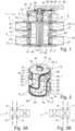
- FIG 1 shows, in a simplified longitudinal section, a first embodiment of an advantageous valve device 1, which is designed to be used in a water circuit of a motor vehicle, in particular a cooling water circuit.
- the valve device 1 has a housing 2, which has a bottom 3 and a circular-cylindrical jacket wall or housing wall 4 extending from the bottom 3, so that the housing 2 is essentially cup-shaped with a U-shaped longitudinal section, as in Figure 1 shown.
- the housing 2 On the side facing away from the base 3, the housing 2 is closed by a housing cover 5, so that a distribution chamber 6 is formed in the housing 2, delimited by the housing cover 5, the base 3 and the housing wall 4, which has a circular-cylindrical cross-section.
- the media connections 7, 8, 9 and 10 are formed on the housing wall 4, each of which opens into the distribution chamber 6.
- the media connections 7, 9 are located at an axial height relative to a geometric axis of rotation or central longitudinal axis 11 of the housing 2.
- the media connections 8 and 10 are located on an axial plane axially spaced therefrom. In cross section or in a Viewed from above, the media connections 7, 9 are located diametrically opposite one another, as are the media connections 8 and 10. All media connections 7 to 10 lie in a plane in which the central longitudinal axis 11 also lies.
- the media connections 7, 8 and the media connections 9, 10 are each located one above the other, and connecting lines that are connected to the media connections 7, 9, 8, 10 are also located in a common plane on different sides of the housing 2, at least in the area of the valve device 1.
- the valve device 1 is designed to save installation space in such a way that the supply or discharge lines or media lines or channels to be connected to it can also be arranged in a space-saving manner or can be fed to the valve device 1.
- valve element 12 is arranged in the distribution chamber 6, through which the media connections 7-10 can be fluidically connected to or separated from one another.
- the valve element 12 is formed in two parts and has a cup-shaped outer element 13 and a distributor element 14 arranged in the outer element 13.
- the outer element 13 has an outer casing 15, which is circularly cylindrical and arranged coaxially with the housing wall 4, and a cover element 16, which has a circular outer contour and from which the outer casing 15 protrudes.
- the outer casing 15 lies axially between the cover element 16 and the base 3.
- the cover element 16 is thus spaced from the base 3, so that the outer element 13 is open towards the base 3.
- the cover element 16 lies above the upper media connections 7, 9, or those further away from the base 3, so that the outer casing 15 extends completely axially from the base 3 past the media connections 7, 8 to the cover element 16.
- FIG 2 shows the valve element 12 in a simplified perspective view.
- the outer element 13 is shown transparently by dashed lines in Figure 2 shown.
- the cover element 16 has a recess 17 in the center, through which an axial projection 18 of the distributor element 14 extends.
- the opening 17 and the axial projection 18 each have a cross-sectional contour that deviates from a circle, wherein the contours of the axial projection 18 and the recess 17 are designed to correspond to one another in such a way that the axial projection 18 is held non-rotatably in the axial recess 17.
- the axial projection 18 and the recess 17 together form an anti-rotation device 19 that acts between the outer element 13 and the distributor element 14.
- the outer casing 15 has four openings 20, distributed evenly over its circumference, in a first axial plane or height.
- the openings 20 are circular and have an inner diameter that is preferably at most equal to the inner diameter of the media connections 7, 8, 9, 10, and preferably slightly smaller. Due to the even distribution of the openings 20 over the circumference of the outer casing 13, two of the openings 20 are diametrically opposite each other.
- the openings 20, 21 are evenly distributed over the circumference of the outer casing 13 such that one opening 21 is located below one of the openings 20 or, in the axial or longitudinal extension of the outer casing 15, one of the openings 20.
- the distributor element 14 arranged in the outer element 13, together with the outer casing 15, forms several, in this case two, media channels.
- the distributor element has an at least substantially cylindrical core 22, from which side walls 23, 24 protrude at least substantially radially.
- the side walls 23, 24 each extend in the manner of a closed ring, so that they have no beginning and no end.
- the side walls 23, 24 each enclose a media channel 25, 26 together with the outer casing 15.
- the side walls 23, 24 protrude up to or almost to the inside of the outer casing 15, so that a space is created which is enclosed by one of the side walls 23, 24, the outer casing 15, and the core 22 and is accessible through the openings 20, 21, which are at the level of the space.
- the space delimited by the respective side wall 23, 24, the core 22, and the outer shell 15 becomes the flow-through media channel 25, 26 through the openings 20, 21.
- the respective space or media channel 25, 26 is each formed in an S-shape, so that the media channel 25, 26 each has a first end closed by the respective side wall 23, 24 in the circumferential direction at the first level of the openings 20 and a closed second end at the level of the openings 21.
- the media channel 25 has a first section 25' extending circumferentially, a second section 25" extending axially of the valve element 12 and a third section extending in the circumferential direction 25′′′, wherein the sections 25' and 25′′′ extend at least substantially over different circumferential sections of the valve element 12.
- the sections 25' and 25′′′ are connected to one another by the central section 25".
- the media channel 26 is designed in particular analogously to the media channel 25 and preferably runs on the side of the distributor element 14 facing away from the media channel 25.
- the end of the media channel 25 in the section 25' is assigned to a first of the openings 20 of the outer casing 15.
- the opposite end of the section 25', at which the section 25' merges into the section 25" is assigned to a second of the openings 20.
- the opposite end of the section 25" is assigned to a first of the openings 21, which is correspondingly also assigned to an end of the section 25′′′.
- the end of the section 25′′′ opposite this end is assigned to a further opening 21.
- the circumferentially distributed openings 20 and 21 are designated 20_1, 20_2, 20_3 and (in Figure 2 not recognizable) 20_4 as well as 21_1, 21_2, 21_3 and (in Figure 2 not visible) 21_4.
- the openings 20_1 and 21_1 are located in axial extension on a line or one above the other or one behind the other, as are the openings 20_2 and 21_2, as well as 20_3 and 21_3 and finally also 20_4 and 21_4, which are on the Figure 2 not visible rear side of the valve element 12.
- the media channel 25 runs, as described above, in an S-shape such that it leads from the opening 20_1 through the section 25' to the opening 20_2, from the opening 20_2 through the section 25" to the opening 21_2, and from there through the section 25′′′ to the opening 21_3.
- the channel 26 formed on the rear side is designed such that it leads from the opening 20_3 to the opening 20_4, from there to the opening 21_4, and from there to the opening 21_1.
- Both channels 25, 26 are thus S-shaped and interact with two openings 20 and two openings 21 in the outer casing 15.
- the previously described anti-twist device 19 ensures that the assignment of the openings 20, 21 to the media channels 25, 26 is always maintained.
- valve element 12 When inserted into the housing 2, the valve element 12 now has the following function, as shown in Figures 3A and 3B
- the valve device 1 is in this case designed as a 4/2-way valve, which therefore has four connections (media connections 7, 8, 9, 10) and two extreme positions, Figures 3A and 3B shown, in which a maximum flow volume is guaranteed.
- valve element 1 In the first switching position according to Figure 3A the valve element 1 is arranged rotated in the housing 2 in such a way that the openings 20_2 and 21_2 are assigned to the media connections 7, 8, and the Figure 2 not visible openings 20_4 and 21_4 to the diametrically opposite media connections 9, 10.
- the openings 21_1 and 21_3 or 20_3 and 21_1 are assigned to a section of the housing 2 or the housing wall 4, which has no opening or no media connection 7, 8, 9, 10.
- the function results that a media flow, which is supplied, for example, through the media connection 7 of the valve device 1, is supplied or forwarded through the section 25" to the opening 21_2 and thus the media connection 8, so that according to the embodiment of Figure 3A
- the medium flows in through media connection 7 and flows out again through media connection 8.
- the medium flows in through media connection 9 and flows out through media connection 10, or vice versa.
- Medium flowing out of the media channel 25 through openings 20 or 21 that are not assigned to one of the media connections 7 to 10 enters the interior of the housing 2, from which it cannot escape, however, because the distribution chamber 6 is tightly sealed by the housing 2 on the one hand and the housing cover 5 on the other.
- valve element If the valve element is rotated by 45°, none of the openings 20, 21 are opposite the media connections 7, 8, 9, 10, but rather the media connections 7, 8, 9, 10 are then closed by the outer casing 15 of the valve element 2, so that the valve device 1 prevents or interrupts a flow.
- the advantageous valve device 1 thus allows different switching positions in which, for example, the media flow is completely interrupted, the media flow from a top media connection 7, 9 to a Figure 1 lower media connection 8, 10, or in which the media flow is directed from an upper media flow 7 to a diametrically opposite lower media connection 10 or from an upper media connection 9 to a diametrically opposite lower media connection 8.
- the flow direction can also be reversed.
- each media connection 7, 8, 9, 10 is assigned a sealing element 27. Because the sealing elements 27 are all of the same design, they are provided with the same reference numerals.
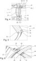
- Figure 4 shows the design of the respective sealing element 27 using the example of the media connection 7 in an enlarged detailed view.
- the sealing element 27 is designed as a sealing ring and is inserted into an opening 28 of the media connection 7 from the distribution chamber 6, so that the sealing element 27 protrudes into the distribution chamber 6 with a sealing lip 29.
- the sealing element 27 is designed such that it bears sealingly on the outside of the outer casing 15, at least in the region of the openings 20, 21, so that it surrounds the respective opening 20, 21 in a sealing ring.
- the radial distance between the outer casing 15 and the housing wall 4, as well as the dimensions of the sealing lip 29, are selected such that the sealing lip 29 is elastically deformed, at least in this operating state, so that a preload force acts, which ensures that the sealing element 27 sits securely and tightly against the outer casing 15. Because the sealing element 27 is radially clamped or tensioned between the outer element 13 and the housing wall 4, spontaneous release of the sealing element 27 is reliably prevented. Viewed in the direction of rotation of the valve element 12 or in the circumferential direction, the sealing element 27 is securely held on the housing wall 4 by the section inserted into the mouth opening 28.
- the sealing lips 29 are preferably designed such that they also rest on the outside of the remaining sections of the outer casing 15 with a residual prestressing force in order to ensure a tight connection there as well and to minimize or prevent leakage.
- the sealing element 27 is in particular inserted directly, i.e. without further, separate support or holding elements, with a section inserted into the mouth opening 28, so that the positive connection is formed directly between the sealing element 27 and the housing wall 4 in the mouth opening 28.
- the sealing lip 29 protrudes freely from the housing wall 4, except for the sealing contact on the outer casing 15, so that it is elastically deformable and thus ensures a high level of tightness.
- the sealing lip 29 is designed in particular such that the sealing element 27 in the region of the sealing lip 29, seen in longitudinal section, is V-shaped or protrudes in a V-shape from the housing wall 4 into the distribution chamber 6.
- the sealing lip 29 has a support ring on its side facing away from the casing wall 15, by means of which the sealing lip 29 is radially supported on the housing wall 4, thereby in particular increasing the preload force.
- the support ring is, as in Figure 4 shown, in particular formed integrally with the sealing lip 29 or with the sealing element 27.
- Figure 5 shows a detailed view of the distributor element 14 in the region of the side wall 23, wherein the side wall 24 is designed analogously to the side wall 23.
- the side wall 23, which projects radially from the core 22, has a free end face 30, which is assigned to the inside of the outer casing 15.
- the end face 30 has an elastically deformable sealing web 31, which extends along the entire end face 30 or the side wall 23 and is designed for tight or sealing contact with the outer casing 15.
- the distributor element 14 is inserted into the outer element 13 with elastic deformation of the respective sealing web 31. This ensures that medium can only pass into or out of the media channels 25, 26 through the openings 20, 21.
- the sealing web 31 is formed integrally with the side wall 23.
- the sealing web 31 is molded onto the end face 30 of the side wall 23 and, in particular, is integrally connected thereto.
- the distributor element 14 is manufactured, in particular, as a two-component component comprising a first, less elastic or hard material for the side walls 23, 24 and the core 22, and a second, more elastic or soft material, thus having greater elasticity than the first material, for the respective sealing web 31.
- the sealing web 31 is protected from damage by securing webs 32 running parallel thereto on the end face 30, which in particular have a lower elasticity and extend radially outwards less far than the sealing web 31.
- Figure 6 shows a further detailed view of the valve device 1 in the area of a sealing element 27.
- Figure 6 that the sealing web 31 lies sealingly against the inside of the outer casing 15 in order to seal the respective media channel 25, 26, and on the other hand shows Figure 6 a further development of the outer jacket 15.
- This has only in the area of the respective opening 20 or 21, each has a radial elevation 33 which surrounds the respective opening 20, 21 in a ring.
- the radial elevation or radial elevation 33 serves, on the one hand, as a guide aid for the sealing lip 29, so that when the valve element 12 is rotated, the latter is safely lifted or pushed over the respective opening 20, 21, so that it cannot jam or tilt one of the openings 20, 21.
- the radial elevation 33 causes the radial distance between the outer casing 15 and the sealing element 27 to be increased in the remaining area of the outer casing 15, thereby reducing the deformation of the sealing lip 29.
- the preload with which the sealing lip 29 is pressed against the outside of the outer casing 15 also decreases.
- the valve element 12 can be rotated with less force in sections where the outer casing 15 is closed than in sections where an opening 20, 21 is provided. This reduces wear and, on the other hand, reduces the power requirement for a drive for adjusting the valve element 12.
- valve element 12 To rotate the valve element 12, it can be mechanically connected to a drive arranged outside the housing 2, as will be explained in more detail below.
- the axial projection 18 of the cover element 16 as shown in Figure 2 shown, an axial recess 34 which has a cross-sectional shape other than a circle.
- a control shaft 35 is inserted into the axial recess 34 with a free end, as shown in Figure 1 shown. Due to the shape of the axial recess 34 and the corresponding shape of the cross section of the control shaft 35 at its free end facing the axial projection 18, a further rotation lock or rotational drive is formed between the control shaft 35 and the valve element 12.
- the control shaft 35 protrudes axially from the housing 2 in sections through an opening 36 in the housing cover 5 with an actuating end 37.
- An optional drive 39 for example an electric motor with or without a transmission gear, is attached to the housing cover 5 and is plugged onto the actuating end 37 in such a way that it can transmit a torque to the control shaft 35 in order to operate the valve element 12 or to rotate it in the distribution chamber 6, so that the above-mentioned valve settings can be carried out automatically.
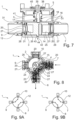
- FIG. 7 shows a further longitudinal sectional view of a second embodiment of the advantageous valve device 1, wherein elements already known from the previous embodiment are provided with the same reference numerals and reference is made to the above description. In the following, only the differences will be discussed.
- the media connections 7, 8, 9, 10 in the second embodiment are all arranged in an axial plane or height of the valve device 1, evenly distributed over the circumference of the housing 2 or the housing wall 4, as can be seen in a plan view of the valve device 1 according to the second embodiment in Figure 8 shown.
- the media channels 25,26 are designed in such a way that they are located in the Figure 8 shown extreme position extend only in the circumferential direction from one opening 20, 21 of the outer shell 15 to the next adjacent opening in the circumferential direction, as for example in Figure 8 Accordingly, there is only one plane of openings 20 or 21, in this case openings 20, in the outer casing, which are evenly distributed over the circumference.
- Figures 9A and 9B show schematic representations of the valve functions of the valve device 1 according to the second embodiment.
- the media connections 9 and 10 as well as the media connections 8 and 7 are each connected to one another, and in a second position ( Figure 9B ) the media connections 9, 8 and the media connections 10, 7 are connected to each other.
- an intermediate position rotation of only 45°
- all media connections 7, 8, 9, 10 are closed by the outer casing 15.
- control shaft 35 also has an axial stop 40, which is formed by a radially projecting annular projection extending over the entire circumference of the control shaft 35.
- a spring element according to the present embodiment a helical spring 41, is held prestressed between the axial projection 40 and the upper side of the cover element 16 facing the housing cover 5 and is arranged coaxially to the control shaft 35.
- the helical spring 41 applies a prestressing force to the valve element 12 as a whole in the direction of the base 3, so that the outer element 13 presses the distributor element 14 against the base 3, thereby holding them axially together.
- the distributor element 14 also has a central axial projection 42 at its end facing the base 3, which lies in an axial recess 43 of the base 3 and thus, together with the base 3 or the axial recess 43, forms a rotary joint 44 for the valve element 12.
- the valve element 12 is thus rotatably mounted in the housing 2 by the control shaft 35 in the housing cover 5 on the one hand and by the rotary joint 44 on the base 3 on the other hand. This is also provided in particular in the first embodiment of FIG. Figure 1 shown.
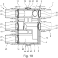
- FIG. 10 shows a third exemplary embodiment of the advantageous valve device 1, wherein elements already known from the preceding exemplary embodiments are provided with the same reference numerals and reference is made to the above description. In the following, only the differences will be discussed.
- the valve device 1 in contrast to the previous embodiments, the valve device 1 according to Figure 10 a further or fifth media connection 45.
- the further media connection 45 is formed or arranged in particular below or in a further axial plane between the base 3 and the previous media connections 7, 8, 9, 10 in the housing wall 4 of the housing 2 and likewise opens into the distribution chamber 6.
- the distribution element 14 has an additional media channel or media channel section 46 which, for example in a rotational position of the distribution element 14 or valve element 12, allows a fluidic connection from the media connections 7 and/or 8 to the media connection 45.
- the outer casing 15 has at least one further opening 47 for the additional media channel or media channel section 46.
- the valve device 1 is thus designed as a 5/3-way valve in this exemplary embodiment.
- valve devices 1 according to the third embodiment can also assume intermediate positions, wherein the number of rotational positions with maximum flow cross-section is limited to the number described above.
- the advantageous design of the valve device 1 fulfills various requirements of the valve device 1 and enables simple adaptation to different boundary conditions. Furthermore, the advantageous design of the valve element 12 ensures that it can be manufactured cost-effectively, for example by injection molding, since radial demolding, in particular of the distributor element 14, is possible even with complicated channel layouts.
- the advantages of the above-described The features known from the exemplary embodiments can also be combined with one another. In addition, further variants of the valve device 1 are also possible, which differ from one another, for example, in the number of media channels 25, 26 and/or media connections 7-10, 45.
- valve device 1 has only two media connections 7 and 8, which lie in a common axial plane or on different axial planes, and interact with a distributor element 14 which, for example, has only one media channel 25.
- the valve device 1 then forms a shut-off valve which either completely opens a flow, completely closes it, or influences the flow rate.
Landscapes
- Engineering & Computer Science (AREA)
- General Engineering & Computer Science (AREA)
- Mechanical Engineering (AREA)
- Chemical & Material Sciences (AREA)
- Combustion & Propulsion (AREA)
- Multiple-Way Valves (AREA)
Claims (17)
- Dispositif de soupape (1), en particulier pour un circuit d'eau d'un véhicule à moteur, avec un carter (2) qui présente une paroi de carter (3) en forme de cylindre entourant côté périphérie une chambre de répartition (6) et au moins deux raccords de fluide (7-10, 45) dans et/ou au niveau de la paroi de carter (3) qui sont respectivement configurés en tant que raccord d'admission ou raccord d'évacuation pour un fluide hydraulique et débouchent à distance l'un par rapport à l'autre dans la chambre de répartition (6), et avec un élément de soupape (12) logé de manière rotative dans la chambre de répartition (6) destiné à une liaison ou une séparation sélectivement hydraulique d'au moins deux des raccords de fluide (7-10, 45) l'un avec l'autre ou l'un de l'autre, dans lequel l'élément de soupape (12) présente une enveloppe externe de forme cylindrique (15) qui est disposée coaxialement par rapport à la paroi de carter (3) et ferme les raccords de fluide (7-10, 45) et en ce que l'élément de soupape (12) présente au moins un canal de fluide (25, 26) qui présente au moins deux ouvertures (20, 21) dans l'enveloppe externe (15) qui sont respectivement associées dans au moins une position de rotation de l'élément de soupape (12) à un raccord de fluide sélectionné des raccords de fluide (7-10, 45) pour libérer les raccords de fluide (7-10, 45) sélectionnés et les relier les uns aux autres de manière hydraulique à travers le canal de fluide (25, 26), caractérisé en ce que respectivement un élément d'étanchéité (27) entourant une ouverture d'embouchure (28) du raccord de fluide (7-10, 45) respectif et conduisant dans la chambre de répartition (6) est associé à chacun des raccords de fluide (7-10, 45), élément d'étanchéité qui fait saillie dans la chambre de répartition (6) avec une lèvre d'étanchéité déformable élastiquement et de forme annulaire (29) pour coopérer de manière étanche avec l'enveloppe externe (15) de l'élément de soupape (12), et en ce que l'enveloppe externe (15) ne présente un sommet radial (33) entourant l'ouverture (20, 21) en tant qu'aide de guidage (33) pour l'élément d'étanchéité (27) que dans la zone des ouvertures (20, 21) respectives de l'enveloppe externe (15).
- Dispositif de soupape selon la revendication 1, caractérisé en ce que l'élément de soupape (12) présente au moins deux canaux de fluide (25, 26) avec respectivement au moins deux ouvertures (20, 21) dans l'enveloppe externe (15).
- Dispositif de soupape selon l'une quelconque des revendications précédentes,
caractérisé en ce qu'au moins un canal de fluide (25, 26) présente au moins une troisième ouverture (20_1, 20_2, 21_2, 21_3), en particulier quatre ouvertures (20_1, 20_2, 21_2, 21_3) dans l'enveloppe externe (15). - Dispositif de soupape selon l'une quelconque des revendications précédentes,
caractérisé en ce que l'élément de soupape (12) est configuré en plusieurs parties et présente un élément externe en forme de coupe (13) qui forme l'enveloppe externe (15) et un élément de répartition (14) disposé dans l'élément externe (13), qui est configuré ouvert au moins par sections vers l'enveloppe externe (15) de sorte que le canal de fluide (25, 26) respectif est formé entre l'élément de répartition (14) et l'enveloppe externe (15). - Dispositif de soupape selon la revendication 4, caractérisé en ce que l'élément de répartition (14) et l'élément externe (13) sont reliés l'un à l'autre de manière fixe en rotation.
- Dispositif de soupape selon l'une quelconque des revendications 4 ou 5,
caractérisé en ce que l'élément de répartition (14) présente un noyau en particulier en forme de cylindre (22) à partir duquel plusieurs parois latérales (23, 24) définissant le tracé des canaux de fluide (25, 26) font saillie radialement et s'approchent jusqu'au ou presque jusqu'au côté interne de l'enveloppe externe (15). - Dispositif de soupape selon la revendication 6, caractérisé en ce que, au niveau du côté avant (30) de chaque paroi latérale (23, 24) orienté vers l'enveloppe externe (15) un épaulement d'étanchéité (31) élastiquement déformable est respectivement disposé, qui s'étend le long de tout le côté avant (30) de la paroi latérale (23, 24) respective et est tendue entre le côté avant (30) et l'enveloppe externe (15).
- Dispositif de soupape selon la revendication 7, caractérisé en ce que l'épaulement d'étanchéité (31) est formé au niveau du côté avant (30), en particulier injecté.
- Dispositif de soupape selon l'une quelconque des revendications 6 à 7,
caractérisé en ce que chaque paroi latérale (23, 24) forme un anneau fermé. - Dispositif de soupape selon l'une quelconque des revendications précédentes,
caractérisé en ce que l'élément d'étanchéité (27) respectif est inséré dans l'ouverture d'embouchure (28) respective de sorte qu'une liaison par complémentarité de formes de l'élément d'étanchéité (27) avec la paroi de carter (4) est assurée au moins dans la direction de rotation de l'élément de soupape (12). - Dispositif de soupape selon l'une quelconque des revendications précédentes,
caractérisé en ce que dans la zone de la lèvre d'étanchéité (29) l'élément d'étanchéité (27) vu en coupe longitudinale fait saillie en forme de V de la paroi de carter (4) jusque dans la chambre de répartition (6). - Dispositif de soupape selon l'une quelconque des revendications précédentes,
caractérisé en ce que le carter (2) présente un fond (3) délimitant axialement la chambre de répartition (6) et en ce que l'élément de répartition (14) configure avec le fond (3) une articulation rotative (44) au niveau d'une extrémité associée au fond (3), dans lequel de préférence l'élément de répartition (14) présente au niveau de l'extrémité associée au fond (3) une saillie axiale (42) ou une cavité axiale, qui configure l'articulation rotative (44) conjointement avec une cavité axiale (43) ou avec une saillie axiale du fond (3). - Dispositif de soupape selon l'une quelconque des revendications précédentes,
caractérisé en ce que l'élément externe (13) présente un élément de couvercle (16) d'où fait saillie l'enveloppe externe (15) et au niveau duquel l'élément de répartition (14) repose axialement au niveau de son extrémité opposée au fond (3). - Dispositif de soupape selon l'une quelconque des revendications précédentes,
caractérisé en ce que le carter (2) présente un couvercle de carter (5) qui est disposé sur le côté de l'élément de soupape (12) opposé au fond (3) et délimite axialement la chambre de répartition (6) et en ce que l'élément de répartition (14) est relié à un arbre de commande (35) sur l'extrémité opposée au fond (3), arbre de commande qui est traversé par une ouverture (36) du couvercle de carter (5), en particulier de manière radiale et étanche, dans lequel de préférence l'arbre de commande (35) présente au moins une butée axiale (40) faisant saillie radialement et en ce qu'un élément formant ressort, en particulier un ressort à vis (41), est maintenu prétendu axialement entre la butée axiale (40) et l'élément de couvercle (16) de l'élément de soupape (12). - Dispositif de soupape selon l'une quelconque des revendications précédentes,
caractérisé en ce que le carter (2) présente au moins trois, en particulier quatre raccords de fluide (7-10, 45) ou plus qui sont disposés répartis en particulier sur un plan axial par-dessus la périphérie du carter (2). - Dispositif de soupape selon l'une quelconque des revendications précédentes,
caractérisé en ce que quatre raccords de fluide (7-10, 45) sont disposés sur deux plans axiaux, de telle sorte que respectivement deux raccords de fluide (7-10, 45) sont superposés axialement et respectivement deux des raccords de fluide (7-10, 45) sont diamétralement opposés. - Dispositif de soupape selon l'une quelconque des revendications précédentes,
caractérisé en ce que le dispositif de soupape (1) est configuré en tant que soupape à 4/2 voies, soupape à 2/2 voies ou en tant que soupape à 5/3 voies.
Applications Claiming Priority (2)
| Application Number | Priority Date | Filing Date | Title |
|---|---|---|---|
| DE102021202181.6A DE102021202181A1 (de) | 2021-03-05 | 2021-03-05 | Ventileinrichtung |
| PCT/EP2022/055616 WO2022184915A1 (fr) | 2021-03-05 | 2022-03-04 | Dispositif de soupape |
Publications (3)
| Publication Number | Publication Date |
|---|---|
| EP4302003A1 EP4302003A1 (fr) | 2024-01-10 |
| EP4302003B1 true EP4302003B1 (fr) | 2025-05-07 |
| EP4302003C0 EP4302003C0 (fr) | 2025-05-07 |
Family
ID=80775360
Family Applications (1)
| Application Number | Title | Priority Date | Filing Date |
|---|---|---|---|
| EP22710395.9A Active EP4302003B1 (fr) | 2021-03-05 | 2022-03-04 | Dispositif de soupape |
Country Status (3)
| Country | Link |
|---|---|
| EP (1) | EP4302003B1 (fr) |
| DE (1) | DE102021202181A1 (fr) |
| WO (1) | WO2022184915A1 (fr) |
Families Citing this family (2)
| Publication number | Priority date | Publication date | Assignee | Title |
|---|---|---|---|---|
| EP4325097B1 (fr) * | 2022-08-19 | 2025-10-08 | TI Automotive Technology Center GmbH | Soupape rotative |
| DE102023201344A1 (de) * | 2023-02-16 | 2024-08-22 | Volkswagen Aktiengesellschaft | Mehrfachventil zum Steuern eines Flusses eines Fluids |
Family Cites Families (14)
| Publication number | Priority date | Publication date | Assignee | Title |
|---|---|---|---|---|
| US2414966A (en) | 1945-02-15 | 1947-01-28 | Parker Appliance Co | Valve assembly |
| CH328844A (de) * | 1955-02-07 | 1958-03-31 | Walter Franke Fa | Mehrweg-Drehschieber |
| JPH01206168A (ja) | 1988-02-10 | 1989-08-18 | Toto Ltd | 弁構造 |
| SE9702236D0 (sv) * | 1997-06-12 | 1997-06-12 | Markaryds Metallarmatur Ab | Flervägsventil |
| FR2844571B1 (fr) * | 2002-09-18 | 2008-02-29 | Valeo Thermique Moteur Sa | Vanne de commande pour un circuit de fluide et circuit comportant cette vanne |
| DE10323900A1 (de) * | 2003-05-26 | 2005-01-05 | J. Eberspächer GmbH & Co. KG | Mehrwegeventil für ein Fahrzeug-Kühl/Heiz-System |
| FR2940396B1 (fr) * | 2008-12-22 | 2013-01-18 | Valeo Systemes Thermiques | Vanne d'alimentation en fluide d'une charge, echangeur de chaleur alimente par la vanne et moteur thermique a combustion interne comportant la vanne |
| DE102012022212B4 (de) | 2012-11-07 | 2023-09-21 | Mack & Schneider Gmbh | Scheibenventil |
| DE102014014964B4 (de) | 2014-10-14 | 2016-10-20 | Henzel Formenbau Gmbh | Mehrwegeventil zur Steuerung von Flüssigkeitskreisen |
| US10344877B2 (en) * | 2015-12-01 | 2019-07-09 | Tesla Motors, Inc. | Multi-port valve with multiple operation modes |
| US11655905B2 (en) * | 2017-04-07 | 2023-05-23 | Robertshaw Controls Company | Multi-port valve |
| DE102018106298B4 (de) * | 2018-03-19 | 2022-07-14 | Hanon Systems | Vorrichtungen zum Regeln eines Durchflusses und Verteilen eines Fluids in einem Fluidkreislauf |
| CN111828687A (zh) | 2019-04-17 | 2020-10-27 | 浙江三花汽车零部件有限公司 | 一种控制阀 |
| CN111288187A (zh) * | 2020-03-27 | 2020-06-16 | 北海职业学院 | 四通换向阀和空调器 |
-
2021
- 2021-03-05 DE DE102021202181.6A patent/DE102021202181A1/de active Pending
-
2022
- 2022-03-04 WO PCT/EP2022/055616 patent/WO2022184915A1/fr not_active Ceased
- 2022-03-04 EP EP22710395.9A patent/EP4302003B1/fr active Active
Also Published As
| Publication number | Publication date |
|---|---|
| WO2022184915A1 (fr) | 2022-09-09 |
| EP4302003C0 (fr) | 2025-05-07 |
| EP4302003A1 (fr) | 2024-01-10 |
| DE102021202181A1 (de) | 2022-09-08 |
Similar Documents
| Publication | Publication Date | Title |
|---|---|---|
| DE19849742B4 (de) | Ventil des Membrantyps | |
| DE60133449T2 (de) | Fluidfilter und ein Fluidfilter-Filterkopf-Gerät | |
| EP1477636B2 (fr) | Dispositif de déphasage d'arbre à cames pour moteur à combustion interne | |
| EP1789711B1 (fr) | Soupape d'evacuation pour un turbocompresseur | |
| DE2753185C2 (de) | Steuerventil, insbesondere für Hilfskraftlenkungen | |
| DE202012012978U1 (de) | Scheibenventil | |
| EP4302003B1 (fr) | Dispositif de soupape | |
| DE102019126035B4 (de) | Ventilvorrichtung | |
| DE102022200540B4 (de) | Drehschieberventil für ein Thermomanagementsystem eines Kraftfahrzeugs | |
| EP4004413B1 (fr) | Distributeur à tiroir rotatif conçu pour un circuit de refroidissement | |
| EP2213850A1 (fr) | Agencement d'étanchéification pour un tiroir rotatif | |
| DE102018111139A1 (de) | Ventileinrichtung | |
| DE3532602A1 (de) | Stroemungssteuerventil | |
| EP1001196B1 (fr) | Soupape de limitation de pression, en particulier pour des véhicules | |
| DE102016122506A1 (de) | Durchflussbegrenzungsventil und Hydraulikanordnung | |
| WO2024188426A1 (fr) | Soupape de commande de fluide, système de refroidissement d'un véhicule automobile et véhicule automobile présentant une telle soupape de commande de fluide | |
| DE202018105534U1 (de) | Ventil | |
| DE202018106532U1 (de) | Ventil zur Steuerung eines Flusses eines Fluids | |
| DE3932269C2 (de) | Druckbegrenzungsventil für einen Hydraulikkreis | |
| DE3623585C2 (fr) | ||
| AT505061A1 (de) | Drehschieberpumpe | |
| DE102021204093A1 (de) | Ventileinrichtung mit Niederhalter | |
| EP4062088B1 (fr) | Soupape rotative | |
| WO1991006795A1 (fr) | Soupape a tiroir | |
| DE102009015976A1 (de) | Ventil mit drehbarem Ventilglied |
Legal Events
| Date | Code | Title | Description |
|---|---|---|---|
| STAA | Information on the status of an ep patent application or granted ep patent |
Free format text: STATUS: UNKNOWN |
|
| STAA | Information on the status of an ep patent application or granted ep patent |
Free format text: STATUS: THE INTERNATIONAL PUBLICATION HAS BEEN MADE |
|
| PUAI | Public reference made under article 153(3) epc to a published international application that has entered the european phase |
Free format text: ORIGINAL CODE: 0009012 |
|
| STAA | Information on the status of an ep patent application or granted ep patent |
Free format text: STATUS: REQUEST FOR EXAMINATION WAS MADE |
|
| 17P | Request for examination filed |
Effective date: 20231005 |
|
| AK | Designated contracting states |
Kind code of ref document: A1 Designated state(s): AL AT BE BG CH CY CZ DE DK EE ES FI FR GB GR HR HU IE IS IT LI LT LU LV MC MK MT NL NO PL PT RO RS SE SI SK SM TR |
|
| DAV | Request for validation of the european patent (deleted) | ||
| DAX | Request for extension of the european patent (deleted) | ||
| GRAP | Despatch of communication of intention to grant a patent |
Free format text: ORIGINAL CODE: EPIDOSNIGR1 |
|
| STAA | Information on the status of an ep patent application or granted ep patent |
Free format text: STATUS: GRANT OF PATENT IS INTENDED |
|
| RIC1 | Information provided on ipc code assigned before grant |
Ipc: F01P 7/14 20060101ALI20240906BHEP Ipc: F01P 7/16 20060101ALI20240906BHEP Ipc: F16K 11/085 20060101AFI20240906BHEP |
|
| INTG | Intention to grant announced |
Effective date: 20240926 |
|
| GRAS | Grant fee paid |
Free format text: ORIGINAL CODE: EPIDOSNIGR3 |
|
| GRAA | (expected) grant |
Free format text: ORIGINAL CODE: 0009210 |
|
| STAA | Information on the status of an ep patent application or granted ep patent |
Free format text: STATUS: THE PATENT HAS BEEN GRANTED |
|
| AK | Designated contracting states |
Kind code of ref document: B1 Designated state(s): AL AT BE BG CH CY CZ DE DK EE ES FI FR GB GR HR HU IE IS IT LI LT LU LV MC MK MT NL NO PL PT RO RS SE SI SK SM TR |
|
| REG | Reference to a national code |
Ref country code: GB Ref legal event code: FG4D Free format text: NOT ENGLISH |
|
| REG | Reference to a national code |
Ref country code: CH Ref legal event code: EP |
|
| REG | Reference to a national code |
Ref country code: DE Ref legal event code: R096 Ref document number: 502022003867 Country of ref document: DE |
|
| REG | Reference to a national code |
Ref country code: IE Ref legal event code: FG4D Free format text: LANGUAGE OF EP DOCUMENT: GERMAN |
|
| U01 | Request for unitary effect filed |
Effective date: 20250604 |
|
| U07 | Unitary effect registered |
Designated state(s): AT BE BG DE DK EE FI FR IT LT LU LV MT NL PT RO SE SI Effective date: 20250611 |
|
| PG25 | Lapsed in a contracting state [announced via postgrant information from national office to epo] |
Ref country code: ES Free format text: LAPSE BECAUSE OF FAILURE TO SUBMIT A TRANSLATION OF THE DESCRIPTION OR TO PAY THE FEE WITHIN THE PRESCRIBED TIME-LIMIT Effective date: 20250507 |
|
| PG25 | Lapsed in a contracting state [announced via postgrant information from national office to epo] |
Ref country code: NO Free format text: LAPSE BECAUSE OF FAILURE TO SUBMIT A TRANSLATION OF THE DESCRIPTION OR TO PAY THE FEE WITHIN THE PRESCRIBED TIME-LIMIT Effective date: 20250807 Ref country code: GR Free format text: LAPSE BECAUSE OF FAILURE TO SUBMIT A TRANSLATION OF THE DESCRIPTION OR TO PAY THE FEE WITHIN THE PRESCRIBED TIME-LIMIT Effective date: 20250808 |
|
| PG25 | Lapsed in a contracting state [announced via postgrant information from national office to epo] |
Ref country code: PL Free format text: LAPSE BECAUSE OF FAILURE TO SUBMIT A TRANSLATION OF THE DESCRIPTION OR TO PAY THE FEE WITHIN THE PRESCRIBED TIME-LIMIT Effective date: 20250507 |
|
| PG25 | Lapsed in a contracting state [announced via postgrant information from national office to epo] |
Ref country code: HR Free format text: LAPSE BECAUSE OF FAILURE TO SUBMIT A TRANSLATION OF THE DESCRIPTION OR TO PAY THE FEE WITHIN THE PRESCRIBED TIME-LIMIT Effective date: 20250507 |
|
| PG25 | Lapsed in a contracting state [announced via postgrant information from national office to epo] |
Ref country code: RS Free format text: LAPSE BECAUSE OF FAILURE TO SUBMIT A TRANSLATION OF THE DESCRIPTION OR TO PAY THE FEE WITHIN THE PRESCRIBED TIME-LIMIT Effective date: 20250807 |
|
| PG25 | Lapsed in a contracting state [announced via postgrant information from national office to epo] |
Ref country code: IS Free format text: LAPSE BECAUSE OF FAILURE TO SUBMIT A TRANSLATION OF THE DESCRIPTION OR TO PAY THE FEE WITHIN THE PRESCRIBED TIME-LIMIT Effective date: 20250907 |