EP4301969B1 - Lufteinlass einer gondel einer flugzeugantriebsanordnung zur förderung einer schubphase und einer schubumkehrphase und verfahren zur verwendung davon - Google Patents
Lufteinlass einer gondel einer flugzeugantriebsanordnung zur förderung einer schubphase und einer schubumkehrphase und verfahren zur verwendung davon Download PDFInfo
- Publication number
- EP4301969B1 EP4301969B1 EP22708112.2A EP22708112A EP4301969B1 EP 4301969 B1 EP4301969 B1 EP 4301969B1 EP 22708112 A EP22708112 A EP 22708112A EP 4301969 B1 EP4301969 B1 EP 4301969B1
- Authority
- EP
- European Patent Office
- Prior art keywords
- upstream
- air inlet
- air flow
- downstream
- leading edge
- Prior art date
- Legal status (The legal status is an assumption and is not a legal conclusion. Google has not performed a legal analysis and makes no representation as to the accuracy of the status listed.)
- Active
Links
Images




Classifications
-
- F—MECHANICAL ENGINEERING; LIGHTING; HEATING; WEAPONS; BLASTING
- F02—COMBUSTION ENGINES; HOT-GAS OR COMBUSTION-PRODUCT ENGINE PLANTS
- F02K—JET-PROPULSION PLANTS
- F02K1/00—Plants characterised by the form or arrangement of the jet pipe or nozzle; Jet pipes or nozzles peculiar thereto
- F02K1/54—Nozzles having means for reversing jet thrust
- F02K1/64—Reversing fan flow
-
- B—PERFORMING OPERATIONS; TRANSPORTING
- B64—AIRCRAFT; AVIATION; COSMONAUTICS
- B64D—EQUIPMENT FOR FITTING IN OR TO AIRCRAFT; FLIGHT SUITS; PARACHUTES; ARRANGEMENT OR MOUNTING OF POWER PLANTS OR PROPULSION TRANSMISSIONS IN AIRCRAFT
- B64D27/00—Arrangement or mounting of power plants in aircraft; Aircraft characterised by the type or position of power plants
- B64D27/02—Aircraft characterised by the type or position of power plants
-
- F—MECHANICAL ENGINEERING; LIGHTING; HEATING; WEAPONS; BLASTING
- F02—COMBUSTION ENGINES; HOT-GAS OR COMBUSTION-PRODUCT ENGINE PLANTS
- F02C—GAS-TURBINE PLANTS; AIR INTAKES FOR JET-PROPULSION PLANTS; CONTROLLING FUEL SUPPLY IN AIR-BREATHING JET-PROPULSION PLANTS
- F02C7/00—Features, components parts, details or accessories, not provided for in, or of interest apart form groups F02C1/00 - F02C6/00; Air intakes for jet-propulsion plants
- F02C7/04—Air intakes for gas-turbine plants or jet-propulsion plants
-
- F—MECHANICAL ENGINEERING; LIGHTING; HEATING; WEAPONS; BLASTING
- F02—COMBUSTION ENGINES; HOT-GAS OR COMBUSTION-PRODUCT ENGINE PLANTS
- F02K—JET-PROPULSION PLANTS
- F02K1/00—Plants characterised by the form or arrangement of the jet pipe or nozzle; Jet pipes or nozzles peculiar thereto
- F02K1/54—Nozzles having means for reversing jet thrust
- F02K1/64—Reversing fan flow
- F02K1/66—Reversing fan flow using reversing fan blades
-
- F—MECHANICAL ENGINEERING; LIGHTING; HEATING; WEAPONS; BLASTING
- F05—INDEXING SCHEMES RELATING TO ENGINES OR PUMPS IN VARIOUS SUBCLASSES OF CLASSES F01-F04
- F05D—INDEXING SCHEME FOR ASPECTS RELATING TO NON-POSITIVE-DISPLACEMENT MACHINES OR ENGINES, GAS-TURBINES OR JET-PROPULSION PLANTS
- F05D2250/00—Geometry
- F05D2250/10—Two-dimensional
- F05D2250/18—Two-dimensional patterned
- F05D2250/181—Two-dimensional patterned ridged
-
- F—MECHANICAL ENGINEERING; LIGHTING; HEATING; WEAPONS; BLASTING
- F05—INDEXING SCHEMES RELATING TO ENGINES OR PUMPS IN VARIOUS SUBCLASSES OF CLASSES F01-F04
- F05D—INDEXING SCHEME FOR ASPECTS RELATING TO NON-POSITIVE-DISPLACEMENT MACHINES OR ENGINES, GAS-TURBINES OR JET-PROPULSION PLANTS
- F05D2250/00—Geometry
- F05D2250/10—Two-dimensional
- F05D2250/18—Two-dimensional patterned
- F05D2250/182—Two-dimensional patterned crenellated, notched
Definitions
- the present invention relates to the field of aircraft propulsion units and more particularly aims at an air inlet for a nacelle of an aircraft propulsion unit.
- an aircraft propulsion assembly 800 extends along a longitudinal axis X oriented from upstream to downstream and comprises a turbomachine 700 and a nacelle 200.
- the turbomachine 700 extends along the longitudinal axis X and is configured to enable the propulsion of the aircraft from the acceleration of an interior air flow F-INT circulating from upstream to downstream in the turbomachine 700.
- the nacelle 200 extends externally around the turbomachine 700 along the longitudinal axis X and makes it possible to guide the interior air flow F-INT in the turbomachine 700.
- upstream and “downstream” are defined with respect to the orientation of the longitudinal axis X.
- the terms “interior” and “exterior” are defined in the radial direction with respect to the longitudinal axis X.
- the turbomachine 700 is of the dual-flow type and comprises upstream a fan 300 mounted to rotate about the longitudinal axis X to accelerate the internal air flow F-INT from upstream to downstream.
- the turbomachine 700 also comprises, downstream of the fan 300, a primary vein 400, radially internal, and a secondary vein 500, radially external, which are separated by a casing 600.
- the casing 600 is configured to guide a first part of the internal air flow F-INT, called primary air flow F1, in the primary vein 400 for the combustion of the fuel and a second part of the internal air flow F-INT, called secondary air flow F2, in the secondary vein 500 in order to generate the thrust of the turbomachine 700.
- the nacelle 200 extends radially outwardly to the fan 300 and delimits the secondary vein 500 radially outwardly.
- the nacelle 200 comprises at its upstream end an air inlet 100 extending peripherally around the longitudinal axis X.
- the air inlet 100 comprises an inner wall 110 facing the longitudinal axis X and an outer wall 120 opposite the inner wall 110, connected together upstream by an air inlet lip 130.
- the air inlet lip 130 has a rounded aerodynamic profile in radial section which allows an upstream air flow F to be separated into the interior air flow F-INT guided by the interior wall 110 and an exterior air flow F-EXT guided by the exterior wall 120.
- the air inlet lip 130 comprises a leading edge 140, defined in each radial section by the point of the air inlet lip 130 located furthest upstream, all of the points forming a closed curve around the longitudinal axis X.
- a thrust phase A is subsequently distinguished ([ Fig.1A ]) in which the secondary air flow F2 circulates from upstream to downstream in the secondary vein 500 and a thrust reversal phase B ([ Fig.1B ]) in which a reverse air flow F-INV circulates from downstream to upstream.
- an interior air flow F-INT originating from the upstream air flow F circulates from upstream to downstream at the foot of the fan 300 to supply the primary air flow F1 as well as in thrust phase A.
- the primary air flow F1 can also be supplied by a portion of the reverse air flow F-INV which bypasses the casing 600.
- variable pitch fan 300 known by its English name “Variable Pitch Fan” abbreviated to “VPF”, which comprises blades whose pitch angle is controlled so as to reverse the direction of circulation of the air flow in the secondary vein 500.
- VPF Variable Pitch Fan
- the reverse air flow F-INV circulates from downstream to upstream in the secondary vein 500 then passes through the fan 300 and is guided upstream by the inner wall 110 of the air inlet 100.
- the reverse air flow F-INV then opposes the upstream air flow F, in particular radially outwardly near the nacelle 200, which allows braking.
- the reverse air flow F-INV then joins the external air flow F-EXT which is admitted through the downstream end of the nacelle 200 into the secondary vein 500.
- the reverse air flow F-INV remains attached to the inlet air flow 100 when it joins the external air flow F-EXT, that is to say that it follows the contour of the air inlet 100 without detaching itself from the inner 110 and outer 120 walls, such a phenomenon being known as the “Coanda effect”.
- Such a phenomenon tends to accelerate the reverse air flow F-INV at the air inlet 100, which generates a local depression DP at the origin of a force opposing the thrust reversal.
- Such a phenomenon is thus likely to reduce the performance of the turbomachine 700 in the thrust reversal phase B, which is undesirable.
- patent applications FR1904087A1 And FR1904094A1 to movably mount respectively deflection members and rectifier vanes on the air inlet, which are deployed during a thrust reversal phase B and retracted during a thrust phase A.
- the patent applications FR1904089A1 And FR1904096A1 alternately teach how to make a portion of the air intake mobile or elastically deformable during the thrust reversal phase B.
- the patent application FR1904092A1 teaches to form internal ducts in the air inlet which are opened during a thrust reversal phase B to divert part of the reverse air flow F-INV.
- the invention thus aims to propose an air inlet for the nacelle of an aircraft propulsion unit making it possible to improve the performance of the turbomachine both during a thrust phase and a thrust reversal phase and having a simple and robust architecture.
- the invention relates to an air intake for a nacelle of an aircraft propulsion unit, said aircraft propulsion unit extending along a longitudinal axis oriented from upstream to downstream and comprising a turbomachine comprising a radially inner primary vein and a radially outer secondary vein configured to guiding from upstream to downstream respectively a primary air flow and a secondary air flow during a thrust phase, said turbomachine comprising upstream a fan mounted to rotate about the longitudinal axis, said aircraft propulsion unit comprising thrust reversal means configured to modify the secondary air flow into a reverse air flow circulating from downstream to upstream in the secondary vein during a thrust reversal phase, said nacelle extending externally around the turbomachine and comprising at its upstream end the air inlet, said air inlet extending peripherally around the longitudinal axis and comprising an inner wall facing the longitudinal axis and an outer wall opposite the inner wall which are connected upstream by an air inlet lip.
- the air inlet comprises a fixed structure with two different profiles, which allows the air inlet to promote performance both during a thrust phase and during a thrust reversal phase with a simple, practical and economical solution. More specifically, the air inlet comprises a thick profile located upstream, which is first encountered by the upstream air flow flowing from upstream to downstream, as well as a thin profile located downstream, which is first encountered by the reverse air flow flowing from downstream to upstream.
- the thick profile facilitates the separation of the upstream air flow into an internal air flow and an external air flow circulating respectively internally and externally to the nacelle, and consequently promotes intake during a thrust phase.
- the thin profile promotes the separation of the reverse air flow from the air intake lip to avoid the appearance of the Coanda effect, and therefore increase performance during a thrust reversal.
- the thick portions together forming the thick profile are advantageously distributed over the entire circumference of the air intake lip to act globally on the air flow. upstream.
- the thin portions together forming the thin profile are advantageously distributed over the entire circumference of the air inlet lip to act globally on the reverse air flow.
- An air inlet lip of non-moving architecture advantageously has a better service life and simplifies maintenance.
- the air intake lip comprises a plurality of joining portions extending between each thick portion and each thin portion, each joining portion comprising a joining leading edge, so as to separate the reverse air flow in rotation, in order to promote a thrust reversal phase.
- each joining portion extends longitudinally between the adjacent upstream leading edge and downstream leading edge.
- Such joining portions advantageously make it possible to ensure continuity between the thick portions and the thin portions, which makes it possible to preserve the aerodynamics of the air intake.
- Such joining portions also ensure, in a manner complementary to the thin portions, the separation of the reverse air flow, in particular when it is in rotation.
- each junction leading edge extends, in projection in a plane tangential to the air inlet lip, along a separation axis forming an angle of between 35° and 70° with the longitudinal axis.
- the reverse air flow includes a gyration generated during its passage through the fan and thus flows in a direction forming an angle of between 30° and 45° with respect to the longitudinal axis.
- the separation axis thus forms an angle of between 80° and 100° with respect to the flow direction of the reverse air flow.
- the reverse air flow preferably arrives substantially perpendicular to the junction leading edge.
- the air inlet lip comprises a corrugated leading edge, preferably comprising a plurality of chevrons.
- the leading edge defined by the set of upstream leading edges, junction leading edges and downstream leading edges, thus has an aerodynamic geometric shape and has two longitudinally separated profiles.
- the upstream leading edge of each thick portion has a curved shape.
- the downstream leading edge of each thin portion has a curved shape. This makes it possible to promote aerodynamics and to present a more deployed shape for a more global action on the air flow.
- the upstream leading edge of each thick portion comprises a convex profile extending circumferentially relative to the longitudinal axis and the convexity of which faces upstream.
- the downstream leading edge of each thin portion comprises a concave profile extending circumferentially relative to the longitudinal axis and whose concavity is turned upstream.
- each thick portion points upstream and each thin portion points downstream.
- the upstream leading edge of each thick portion has a convex profile opposite the concave profile of the downstream leading edge of each thin portion. This makes it possible to ensure a substantially equitable distribution of the upstream leading edge relative to the downstream leading edge.
- the upstream leading edges each having an upstream point all of the upstream points are aligned transversely relative to the longitudinal axis, and preferably, belong to an upstream circle whose longitudinal axis passes through the center.
- the downstream leading edges each having an upstream point all of the upstream points are aligned transversely relative to the longitudinal axis, and preferably, belong to a downstream circle whose longitudinal axis passes through the center. This allows the upstream leading edges to act together on the upstream airflow and the downstream leading edges to act together on the reverse airflow, for greater efficiency.
- the radii of curvature verify the following relationship: 1.8 * r ⁇ R ⁇ 2.2 • r. This makes it possible to have a sufficiently thick upstream leading edge and a sufficiently thin leading edge, while limiting the mass and ensuring the robustness of the air intake.
- the junction portions also have an aerodynamic shape which ensures the progressive transition between the two profiles.
- each junction portion is defined in a radial plane by a radius of curvature R* at the leading edge of the junction which satisfies the following relation: r ⁇ R* ⁇ R.
- each thick portion in at least one transverse plane located downstream of the downstream leading edges, has a radial thickness greater than a radial thickness of each thin portion. This makes it possible to guide the internal air flow downstream of the upstream leading edges during a thrust phase.
- the thick portions advantageously delimit, internally to the nacelle, preferred circulation corridors for the internal air flow while the thin portions delimit preferred circulation corridors for the reverse air flow.
- each thick portion projects inwardly from the inlet. air, so as not to modify the external shape of the air intake lip and to maintain its aerodynamics.
- the invention also relates to the assembly of an air intake as described above and a fan, preferably forming the thrust reversal means.
- a fan with variable-pitch blades is advantageously suitable for aircraft propulsion units with a high bypass ratio, namely whose ratio of the mass of the secondary air flow to the mass of the primary air flow is greater than 16.
- the invention further relates to a nacelle of an aircraft propulsion unit, said aircraft propulsion unit extending along a longitudinal axis oriented from upstream to downstream and comprising a turbomachine comprising a radially inner primary vein and a radially outer secondary vein configured to guide from upstream to downstream respectively a primary air flow and a secondary air flow during a thrust phase, said turbomachine comprising upstream a fan mounted to rotate about the longitudinal axis, said aircraft propulsion unit comprising thrust reversal means configured to modify the secondary air flow into a reverse air flow circulating from downstream to upstream in the secondary vein during a thrust reversal phase, said nacelle extending externally around the turbomachine and comprising at its upstream end an air inlet as described above.
- the invention also relates to an aircraft propulsion assembly extending along a longitudinal axis oriented from upstream to downstream and comprising a turbomachine comprising a radially inner primary vein and a radially outer secondary vein configured to guide from upstream to downstream respectively a primary air flow and a secondary air flow during a thrust phase, said turbomachine comprising upstream a fan mounted to rotate about the longitudinal axis, said aircraft propulsion assembly comprising thrust reversal means configured to modify the secondary air flow into a reverse air flow circulating from downstream to upstream in the secondary vein during a thrust reversal phase, said aircraft propulsion assembly comprising a nacelle extending externally around the turbomachine and comprising at its upstream end an air inlet as described above, the fan preferably forming the thrust reversal means.
- such a method is advantageously free of a step of moving and/or deforming the air inlet, the latter retaining its shape during a thrust reversal phase, which gives it a simple, robust, durable and economical architecture.
- the method is also simple and quick to implement, with no latency time to switch from one phase to another.
- the fan blade pitch is changed to form the reverse airflow.
- the invention relates to an aircraft propulsion assembly 8 with an innovative aerodynamic profile, in particular at the level of the air intake 1, to promote performance both during a thrust phase A and during a thrust reversal phase B.
- the aircraft propulsion assembly 8 extends along a longitudinal axis X oriented from upstream to downstream and comprises a turbomachine 7 and a nacelle 2.
- the turbomachine 7 extends along the longitudinal axis X and is configured to enable the propulsion of the aircraft from the acceleration of an internal air flow F-INT circulating from upstream to downstream in the turbomachine 7.
- the nacelle 2 extends externally around the turbomachine 7 along the longitudinal axis X and makes it possible to guide the internal air flow F-INT in the turbomachine 7.
- upstream and “downstream” are defined with respect to the orientation of the longitudinal axis X.
- the terms “internal” and “external” are defined in the radial direction with respect to the longitudinal axis X.
- the turbomachine 7 is of the dual-flow type and comprises upstream a fan 3 mounted to rotate about the longitudinal axis X to accelerate the internal air flow F-INT from upstream to downstream.
- the turbomachine 7 also comprises, downstream of the fan 3, a primary vein 4, radially internal, and a secondary vein 5, radially external, which are separated by a casing 6.
- the casing 6 is configured to guide a first part of the internal air flow F-INT, called primary air flow F1, in the primary vein 4 for the combustion of the fuel and a second part of the internal air flow F-INT, called secondary air flow F2, in the secondary vein 5 in order to generate the thrust of the turbomachine 7.
- the nacelle 2 extends radially outwardly to the fan 3 and delimits radially outwardly the secondary vein 5.
- the nacelle 2 comprises at its upstream end an air inlet 1 extending peripherally around the longitudinal axis X.
- the air inlet 1 comprises an inner wall 11 facing the longitudinal axis X and an outer wall 12 opposite the inner wall 11, connected together upstream by an air inlet lip 13.
- the air inlet lip 13 makes it possible to separate an upstream air flow F into the interior air flow F-INT guided by the interior wall 11 and an exterior air flow F-EXT guided by the exterior wall 12.
- the air inlet lip 13 has a leading edge 14, defined in each radial section by the point of the air inlet lip 13 located furthest upstream, all of the points forming a closed curve around the longitudinal axis X.
- the fan 3 is of the variable pitch type, known by its English name “Variable Pitch Fan” abbreviated to “VPF”, that is to say that it comprises blades whose pitch angle is controlled so as to reverse the direction of circulation of the air flow in the secondary vein 5.
- VPF Variable Pitch Fan
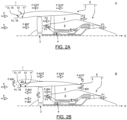
- a thrust phase A ([ Fig.2A ]) in which the secondary air flow F2 circulates from upstream to downstream in the secondary vein 5
- a thrust reversal phase B [ Fig.2B ]) in which a reverse air flow F-INV circulates from downstream to upstream to reduce the braking distance of an aircraft, in particular during landing.
- the reverse air flow F-INV circulates from downstream to upstream in the secondary vein 5 then passes through the fan 3 and is guided upstream by the inner wall 11 of the air inlet 1.
- the reverse air flow F-INV then opposes the upstream air flow F, in particular radially outwardly near the nacelle 2, which allows braking.
- the reverse air flow F-INV then joins the external air flow F-EXT which is admitted by the downstream end of the nacelle 2 into the secondary vein 5.
- an internal air flow F-INT coming from the upstream air flow F circulates from upstream to downstream at the foot of the fan 3 to supply the primary air flow F1 as well as in thrust phase A.
- the primary air flow F1 can also be supplied by a part of the reverse air flow F-INV which bypasses the casing 6.
- variable-pitch fan 3 is particularly suitable for aircraft propulsion units 8 with a high dilution rate, i.e. whose ratio of the mass of the secondary air flow F2 to the mass of the primary air flow F1 is greater than 16, because it makes it possible to optimize the on-board mass.
- the air inlet lip 13 comprises thick portions 15 and thin portions 17 distributed alternately over the circumference of the air inlet lip 13. It is specified that the air inlet lip 13 has a thickness which is defined here and subsequently radially relative to the longitudinal axis X.
- each thick portion 15 comprises an upstream leading edge 16 configured to separate the upstream air flow F into the exterior air flow F-EXT guided by the exterior wall 12 and the interior air flow F-INT guided by the interior wall 11, in order to promote a thrust phase A.
- each thin portion 17 comprises a downstream leading edge 18, located longitudinally downstream of each upstream leading edge 16, configured to generate a separation zone ZD of the reverse air flow F-INV at the level of the air inlet lip 13, in order to promote a thrust reversal phase B.
- the air inlet lip 13 also comprises junction portions 19 extending between each thick portion 15 and each thin portion 17.
- Each junction portion 19 comprises a junction leading edge 20 configured to detach the reverse air flow F-INV in a manner complementary to the thin portions 17, in order to promote a thrust reversal phase B.
- the air inlet lip 13 comprises a fixed structure, free of any moving and/or deformable part, which is suitable for both the thrust phase A and the thrust reversal phase B. More specifically, the air inlet lip 13 comprises an upstream profile and a downstream profile configured to promote performance respectively during a thrust phase A and during a thrust reversal phase B.
- the upstream air flow F in fact first encounters the upstream profile, namely the thick portions 15, while the reverse air flow F-INV first encounters the downstream profile, namely the thin portions 17.
- the upstream air flow F and the reverse air flow F-INV are thus advantageously mainly guided respectively by the thick portions 15 and the thin portions 17.
- the thick portions 15, thin 17 and junction 19 are organized as follows: a thick portion 15, a junction portion 19, a thin portion 17 and a junction portion 19 together form an elementary pattern that is repeated over the entire circumference of the air inlet 1, in this example eight times.
- the number of thick portions 15 and thin portions 17 is equal to equally promote the thrust A and thrust reversal B phases.
- the number of junction portions 19 is twice that of thick portions 15, and therefore of thin portions 17.
- n the number of thick portions 15 and N the number of blades of the fan 3
- the number n of thick portions 15 satisfies the following relationship, for acoustic reasons: 0.5 * N ⁇ n ⁇ 2 * N, with n ⁇ N.
- the number n of thick portions 15 is equal to eight.
- all of the thick portions 15 have an identical shape and size to promote the admission of the internal air flow F-INT in a uniform manner over the entire circumference of the air inlet 1.
- all of the thin portions 17 have an identical shape and size to promote the separation of the reverse air flow F-INV in a uniform manner over the entire circumference of the air inlet 1.
- the thick portions 15 and the thin portions 17 extend over an equal circumferential length to promote the thrust phase A and the thrust reversal phase B equally. It goes without saying that at least part of the thick portions 15 and/or the thin portions 17 could have a different shape and/or size.
- the upstream leading edge 16 of each thick portion 15 has a curved profile of convex shape whose convexity is oriented upstream.
- the downstream leading edge 18 of each thin portion 17 has a curved profile of concave shape whose concavity is oriented upstream. It is specified that the upstream leading edge 16 of a thick portion 15 is defined in each radial section of said thick portion 15 by the point of the air inlet lip 13 located furthest upstream. Similarly, the downstream leading edge 18 of a thin portion 17 is defined in each radial section of said thin portion 17 by the point of the air inlet lip 13 located furthest upstream.
- the upstream leading edges 16 have a profile opposite to that of the downstream leading edges 18 along an axis of symmetry transverse to the longitudinal axis X.
- each upstream leading edge 16 has an upstream point P16, defined as the point of the upstream leading edge 16 located furthest upstream.
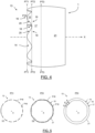
- the upstream points P16 of the upstream leading edges 16 are aligned in a transverse plane PT1 relative to the longitudinal axis X, and preferably belong to the same circle C1 in the transverse plane PT1 and with a center crossed by the longitudinal axis X ([ Fig.5 ]).
- each downstream leading edge 18 has an upstream point P18, defined as the point of the downstream leading edge 18 located furthest upstream.
- the upstream points P18 of the downstream leading edges 18 are aligned in a transverse plane PT2 located downstream of the transverse plane PT1, and preferably, belong to the same circle C2 in the transverse plane PT2 and with a center crossed by the longitudinal axis X ([ Fig.5 ]).
- Such an alignment allows a more homogeneous and global guidance of the upstream air flow F in thrust phase A and of the reverse air flow F-INV in thrust reversal phase B.
- each junction portion 19 connects a thick portion 15 and a thin portion 17 and each junction leading edge 20 connects an upstream leading edge 16 and a downstream leading edge 18.
- the junction portions 19 are configured to detach the reverse air flow F-INV in an auxiliary manner to the thin portions 17. More precisely, the junction portions 19 make it possible to detach the reverse air flow F-INV in rotation following its passage through the fan 3. In fact, the reverse air flow F-INV circulates at the air inlet lip 13 in a direction forming an angle of between 30° and 45° with the longitudinal axis X.
- the junction portions 19 extend over an equal circumferential length so as to act homogeneously and globally on the reverse air flow F-INV.
- the junction leading edges 20 preferably have an identical shape, the junction leading edges 20 connecting the same upstream leading edge 16, called “right junction leading edge 20-1” and “left junction leading edge 20-2”, being oriented in opposite directions along a longitudinal axis of symmetry. It is specified that the junction leading edge 20 of a junction portion 19 is defined in each radial section of said junction portion 19 by the point of the air inlet lip 13 located furthest upstream. It goes without saying that at least part of the junction portions 19 could have a different shape and/or size.
- each junction leading edge 20 extends, in projection along a tangential plane PV to the air inlet lip 13, along a separation axis X20 forming an angle ⁇ relative to the longitudinal axis X of between 35° and 70°.
- the angle ⁇ of the right junction leading edges 20-1 is equal to and oriented in the opposite manner to that of the left junction leading edges 20-2.
- the reverse air flow F-INV thus circulates substantially perpendicularly relative to the right junction leading edges 20-1, which promotes the separation of the reverse air flow F-INV.
- the flow direction of the reverse air flow F-INV preferably forms an angle with the separation axis X20 of the edges straight junction attack edges 20-1 between 80° and 100°. It goes without saying that the reverse air flow F-INV could alternatively flow substantially perpendicularly to the left junction attack edges 20-2 instead of the straight junction attack edges 20-1.
- the leading edge 14 of the air inlet lip 13 is thus formed by the set of upstream leading edges 16, the junction leading edges 20 and the downstream leading edges 18 and is in the form of a closed undulating curve, preferably comprising a set of chevrons CH.
- a chevron CH corresponds to the set of an upstream leading edge 16, the two adjacent downstream half leading edges 18 and the two junction leading edges 20 connecting them.
- Such a shape is advantageously simple and has two longitudinally separated profiles for the thrust phase A and the thrust reversal phase B.
- the radius of curvature R at an upstream leading edge 16 varies over the circumference of the thick portion 15 and is at a maximum at the upstream point P16.
- the radius of curvature r at a downstream leading edge 18 varies over the circumference of the thin portion 17 and is at a minimum at the upstream point P18.
- the radii of curvature R, r satisfy the following relationship R > 1.5 * r, more preferably R ⁇ 3 * r, and preferentially 1.8 * r ⁇ R ⁇ 2.2 * r.
- the thickness of a thick portion 15 near the upstream leading edge 16 is thus substantially twice as great as that of a thin portion 17 near the downstream leading edge 18.
- the radius of curvature R* at a junction leading edge 19 decreases from upstream to downstream, preferably linearly, and satisfies the following relationship: r ⁇ R* ⁇ R. This makes it possible to promote both the separation of the upstream air flow F and the separation of the reverse air flow F-INV while ensuring the aerodynamics and continuity of the air inlet lip 13.
- each thick portion 15 preferably has a thickness E greater than the thickness e of a thin portion 17 in the same transverse plane PT3 located downstream of the downstream leading edges 18, and therefore of the planes transverse PT1, PT2.
- Each junction portion 19 has in the transverse plane PT3 a thickness E* verifying the following relationship: e ⁇ E* ⁇ E.
- each thick portion 15 extends inwardly relative to the thin portions 17 in the transverse plane PT3.
- the thick portions 15 and the thin portions 17 form circulation corridors for the upstream air flow F and the reverse air flow F-INV along the entire length of the air inlet 1.
- the air inlet 1 further retains an aerodynamic exterior shape similar to that of the prior art, with only its interior shape being modified.
- a method of using the aircraft propulsion unit 8 according to the invention is described below during a thrust phase A and during a thrust reversal phase B.
- the blades of the variable-pitch fan 3 are oriented so as to allow the air flow to circulate from upstream to downstream.
- the upstream air flow F circulating from upstream to downstream arrives at the upstream leading edges 16 of the thick portions 15, which separate the upstream air flow F into the external air flow F-EXT and the internal air flow F-INT.
- the thick portions 15 advantageously promote the separation of the upstream air flow F and therefore the admission of the internal air flow F-INT to the turbomachine 7 to ensure its thrust.
- the pitch of the blades of the fan 3 is modified to reverse the direction of the secondary air flow F2 in the secondary vein 5.
- a reverse air flow F-INV thus flows from downstream to upstream and passes through the fan 3 where it is driven in a rotation.
- the reverse air flow F-INV then arrives at the downstream leading edges 18 of the thin portions 17 and the junction leading edges 20 of the junction portions 19 which together promote its separation from the air inlet lip 13.
- a separation zone ZD then forms in contact with the air inlet lip 13 which prevents any local depression harmful to the thrust reversal B.
- the transition from a thrust phase A to a thrust reversal phase B is advantageously simple and quick to achieve, requiring only the orientation of the blades of the fan 3 to be modified. No step of moving or deforming the air inlet 1 is necessary as in the prior art. The profile of the air inlet 1 remains unchanged between the thrust phase A and the thrust reversal phase B.
- FIG. 8A, 8B , 8C And 8D illustrate alternative embodiments of the invention described above.
- the upstream points P16 of the upstream leading edges 16 belong to an ellipse C1' in the transverse plane PT1 and with a center crossed by the longitudinal axis X.
- the upstream points P18 of the leading edges downstream attack edges 18 belong to an ellipse C2' in the transverse plane PT2 and with a center crossed by the longitudinal axis X.
- the upstream points P16 of the upstream attack edges 16 could belong to a closed curve of any shape in the transverse plane PT1, other than the circle C1 of the [ Fig.5 ] and the ellipse C1' of the [ Fig.8A ], so as to adapt to the shape of nacelle 2 in particular.
- the closed curve of the upstream points P16 of the upstream leading edges 16 could be different from that of the upstream points P18 of the downstream leading edges 18.
- the upstream points P16 of the upstream leading edges 16 might not be aligned in a transverse plane PT1.
- the upstream points P18 of the downstream leading edges P18 are also belong to an inclined plane PT1' forming an angle ⁇ relative to the longitudinal axis X in a circumferential plane.
- the upstream points P18 of the downstream leading edges 18 belong to an inclined plane PT2' parallel to the inclined plane PT1' in this example.
- the [ Fig.8C ] illustrates another example in which the upstream points P16, P18 of the upstream leading edges 16 and downstream 18 belong to a closed curved curve PT1", PT2" in a circumferential plane, of concave shape whose concavity is turned upstream in this example.
- the upstream points P16 of the upstream leading edges 16 could be aligned in a transverse plane PT1 but not the upstream points P18 of the downstream leading edges 18, or vice versa as illustrated in the [ Fig.8D ].
- the upstream points P18 of the downstream leading edges 18 are aligned in a transverse plane PT2 but not the upstream points P16 of the upstream leading edges. This makes it possible to obtain chevrons of different lengths.
Landscapes
- Engineering & Computer Science (AREA)
- Chemical & Material Sciences (AREA)
- Combustion & Propulsion (AREA)
- Mechanical Engineering (AREA)
- General Engineering & Computer Science (AREA)
- Aviation & Aerospace Engineering (AREA)
- Structures Of Non-Positive Displacement Pumps (AREA)
- Wind Motors (AREA)
Claims (10)
- Lufteinlass (1) der Gondel (2) einer Luftfahrzeug-Antriebseinheit (8), wobei sich die Luftfahrzeug-Antriebseinheit (8) gemäß einer Längsachse (X) erstreckt, die von stromaufwärts nach stromabwärts gerichtet ist, und eine Turbomaschine (7) umfasst, die einen radial inneren Primärkanal (4) und einen radial äußeren Sekundärkanal (5) umfasst, die ausgelegt sind, um von stromaufwärts nach stromabwärts jeweils einen Primärluftstrom (F1) und einen Sekundärluftstrom (F2) während einer Schubphase (A) zu führen, wobei die Turbomaschine (7) stromaufwärts ein Gebläse (3) umfasst, das um die Längsachse (X) drehbar angebracht ist, wobei die Luftfahrzeug-Antriebseinheit (8) Schubumkehrmittel umfasst, die ausgelegt sind, um den Sekundärluftstrom (F2) in einen umgekehrten Luftstrom (F-INV) umzuwandeln, der während einer Schubumkehrphase (B) von stromabwärts nach stromaufwärts im Sekundärkanal (5) strömt, wobei sich die Gondel (2) außen um die Turbomaschine (7) herum erstreckt und an ihrem stromaufwärts gelegenen Ende den Lufteinlass (1) umfasst, wobei sich der Lufteinlass (1) peripher um die Längsachse (X) erstreckt und eine der Längsachse (X) zugewandte Innenwand (11) und eine der Innenwand (11) gegenüberliegende Außenwand (12) umfasst, die stromaufwärts durch eine Lufteinlasslippe (13) verbunden sind, wobei der Lufteinlass (1) dadurch gekennzeichnet ist, dass:• die Lufteinlasslippe (13) eine Dicke aufweist, die radial zur Längsachse (X) definiert ist, und eine Vielzahl von dicken Abschnitten (15) und eine Vielzahl von dünnen Abschnitten (17) umfasst, die abwechselnd auf dem Umfang der Lufteinlasslippe (13) verteilt sind,• jeder dicke Abschnitt (15) eine stromaufwärts gelegene Vorderkante (16) aufweist, die ausgelegt ist, um einen stromaufwärts gelegenen Luftstrom (F), der von stromaufwärts nach stromabwärts zirkuliert, in einen Außenluftstrom (F-EXT), der von der Außenwand (12) geführt wird, und einen Innenluftstrom (F-INT), der von der Innenwand (11) geführt wird, zu trennen, um eine Schubphase (A) zu begünstigen,• jeder dünne Abschnitt (17) eine stromabwärts gelegene Vorderkante (18) aufweist, die sich in Längsrichtung stromabwärts von jeder stromaufwärts gelegenen Vorderkante (16) befindet und ausgelegt ist, um den umgekehrten Luftstrom (F-INV) im Bereich der Lufteinlasslippe (13) zu lösen, um eine Schubumkehrphase (B) zu begünstigen.
- Lufteinlass (1) nach Anspruch 1, wobei die Lufteinlasslippe (13) eine Vielzahl von Verbindungsabschnitten (19) umfasst, die sich zwischen jedem dicken Abschnitt (15) und jedem dünnen Abschnitt (17) erstrecken, wobei jeder Verbindungsabschnitt (19) eine Verbindungsvorderkante (20) aufweist, um den umgekehrten Luftstrom (F-INV) beim Kreisen zu lösen, um eine Schubumkehrphase (B) zu begünstigen.
- Lufteinlass (1) nach Anspruch 2, wobei sich jede Verbindungsvorderkante (20) in der Projektion in einer Tangentialebene (PV) zur Lufteinlasslippe (13) gemäß einer Ablöseachse (X20) erstreckt, die mit der Längsachse (X) einen Winkel (α) zwischen 35° und 70° bildet.
- Lufteinlass (1) nach einem der Ansprüche 1 bis 3, wobei die Lufteinlasslippe (13) vorzugsweise eine gewellte Vorderkante (14) aufweist, die eine Vielzahl von Zacken (CH) umfasst.
- Lufteinlass (1) nach einem der Ansprüche 1 bis 4, wobei die stromaufwärts gelegene Vorderkante (16) jedes dicken Abschnitts (15) ein konvexes Profil aufweist, das sich in Bezug auf die Längsachse (X) umfanggemäß erstreckt und dessen Konvexität nach stromaufwärts gerichtet ist.
- Lufteinlass (1) nach einem der Ansprüche 1 bis 5, wobei die stromabwärts gelegene Vorderkante (18) jedes dünnen Abschnitts (17) ein konkaves Profil aufweist, das sich in Bezug auf die Längsachse (X) umfanggemäß erstreckt und dessen Konkavität nach stromaufwärts gerichtet ist.
- Lufteinlass (1) nach einem der Ansprüche 1 bis 6, wobei die Lufteinlasslippe (13) eine Hülle (21) umfasst:• die in jeder radialen Ebene (PR1) eines dicken Abschnitts (15) durch einen Krümmungsradius (R) an der stromaufwärts gelegenen Vorderkante (16) definiert ist,• die in jeder radialen Ebene (PR2) eines dünnen Abschnitts (17) durch einen Krümmungsradius (r) an der stromabwärts gelegenen Vorderkante (18) definiert ist,• wobei die Krümmungsradien (R, r) die folgende Relation erfüllen: R > 1,5 * r und vorzugsweise R < 3 * r.
- Lufteinlass (1) nach einem der Ansprüche 1 bis 7, wobei in mindestens einer Querebene (PT3) stromabwärts der stromabwärts gelegenen Vorderkanten (18) jeder dicke Abschnitt (15) eine radiale Dicke (E) aufweist, die größer ist als eine radiale Dicke (e) jedes dünnen Abschnitts (17), wobei sich jeder dicke Abschnitt (15) vorzugsweise vorspringend in das Innere des Lufteinlasses (1) erstreckt.
- Luftfahrzeug-Antriebseinheit (8), die sich gemäß einer von stromaufwärts nach stromabwärts gerichteten Längsachse (X) erstreckt und eine Turbomaschine (7) mit einem radial inneren Primärkanal (4) und einem radial äußeren Sekundärkanal (5) umfasst, die ausgelegt sind, um von stromaufwärts nach stromabwärts jeweils einen Primärluftstrom (F1) und einen Sekundärluftstrom (F2) während einer Schubphase (A) zu führen, wobei die Turbomaschine (7) stromaufwärts ein Gebläse (3) umfasst, das um die Längsachse (X) drehbar angebracht ist, wobei die Luftfahrzeug-Antriebseinheit (8) Schubumkehrmittel umfasst, die ausgelegt sind, um den Sekundärluftstrom (F2) in einen umgekehrten Luftstrom (F-INV) umzuwandeln, der während einer Schubumkehrphase (B) von stromabwärts nach stromaufwärts im Sekundärkanal (5) strömt, wobei die Luftfahrzeug-Antriebseinheit (8) eine Gondel (2) umfasst, die sich außen um die Turbomaschine (7) herum erstreckt und an ihrem stromaufwärts gelegenen Ende einen Lufteinlass (1) nach einem der Ansprüche 1 bis 8 umfasst, wobei das Gebläse (3) vorzugsweise die Schubumkehrmittel bildet.
- Verfahren zur Verwendung eines Lufteinlasses (1) einer Gondel (2) einer Luftfahrzeug-Antriebseinheit (8) nach einem der Ansprüche 1 bis 8, wobei:• während einer Schubphase (A) jeder dicke Abschnitt (15) der Lufteinlasslippe (13) einen stromaufwärts gerichteten Luftstrom (F), der von stromaufwärts nach stromabwärts strömt, in einen von der Außenwand (12) geführten Außenluftstrom (F-EXT) und einen von der Innenwand (11) geführten Innenluftstrom (F-INT) trennt, und• in einer Schubumkehrphase (B) jeder dünne Abschnitt (17) der Lufteinlasslippe (13) einen umgekehrten Luftstrom (F-INV) löst, der im Bereich der Lufteinlasslippe (13) von stromabwärts nach stromaufwärts strömt.
Applications Claiming Priority (2)
| Application Number | Priority Date | Filing Date | Title |
|---|---|---|---|
| FR2101970A FR3120254B1 (fr) | 2021-03-01 | 2021-03-01 | Entrée d’air de nacelle d’ensemble propulsif d’aéronef pour favoriser une phase de poussée et une phase d’inversion de poussée et son procédé d’utilisation |
| PCT/EP2022/054590 WO2022184530A1 (fr) | 2021-03-01 | 2022-02-24 | Entrée d'air de nacelle d'ensemble propulsif d'aéronef pour favoriser une phase de poussée et une phase d'inversion de poussée et son procédé d'utilisation |
Publications (2)
| Publication Number | Publication Date |
|---|---|
| EP4301969A1 EP4301969A1 (de) | 2024-01-10 |
| EP4301969B1 true EP4301969B1 (de) | 2024-12-04 |
Family
ID=75339953
Family Applications (1)
| Application Number | Title | Priority Date | Filing Date |
|---|---|---|---|
| EP22708112.2A Active EP4301969B1 (de) | 2021-03-01 | 2022-02-24 | Lufteinlass einer gondel einer flugzeugantriebsanordnung zur förderung einer schubphase und einer schubumkehrphase und verfahren zur verwendung davon |
Country Status (5)
| Country | Link |
|---|---|
| US (1) | US12320314B2 (de) |
| EP (1) | EP4301969B1 (de) |
| CN (1) | CN116940752A (de) |
| FR (1) | FR3120254B1 (de) |
| WO (1) | WO2022184530A1 (de) |
Families Citing this family (1)
| Publication number | Priority date | Publication date | Assignee | Title |
|---|---|---|---|---|
| FR3116043B1 (fr) * | 2020-11-09 | 2023-04-28 | Safran Aircraft Engines | Entrée d’air de nacelle d’ensemble propulsif d’aéronef pour favoriser une phase d’inversion de poussée |
Family Cites Families (12)
| Publication number | Priority date | Publication date | Assignee | Title |
|---|---|---|---|---|
| US20050274103A1 (en) * | 2004-06-10 | 2005-12-15 | United Technologies Corporation | Gas turbine engine inlet with noise reduction features |
| CN101716995A (zh) * | 2009-10-12 | 2010-06-02 | 章成谊 | 波形翼与物体的波形表面 |
| FR3022218B1 (fr) * | 2014-06-12 | 2016-07-15 | Airbus Operations Sas | Nacelle d'aeronef comprenant une entree d'air amelioree |
| US10145301B2 (en) * | 2014-09-23 | 2018-12-04 | Pratt & Whitney Canada Corp. | Gas turbine engine inlet |
| US10260417B2 (en) * | 2015-12-22 | 2019-04-16 | General Electric Company | Air intake turboprop assemblies |
| FR3057620B1 (fr) * | 2016-10-18 | 2020-07-31 | Safran Aircraft Engines | Ensemble propulsif comprenant un conduit d'alimentation du generateur de gaz dans un carter inter-veine |
| US11053888B2 (en) | 2017-11-01 | 2021-07-06 | The Boeing Company | Fan cowl with a serrated trailing edge providing attached flow in reverse thrust mode |
| FR3078099B1 (fr) * | 2018-02-16 | 2020-09-11 | Safran Aircraft Engines | Structure a profil en serrations avec des surfaces traitees |
| GB201815759D0 (en) * | 2018-09-27 | 2018-11-14 | Rolls Royce Plc | Nacelle intake |
| FR3095241B1 (fr) * | 2019-04-17 | 2021-06-25 | Safran Aircraft Engines | Entrée d’air de nacelle de turboréacteur comprenant une conduite de circulation pour favoriser une phase d’inversion de poussée |
| FR3095194B1 (fr) * | 2019-04-17 | 2021-08-13 | Safran Aircraft Engines | Entrée d’air de nacelle de turboréacteur comprenant un dispositif de déviation pour favoriser une phase d’inversion de poussée |
| US11486306B2 (en) * | 2020-06-18 | 2022-11-01 | The Boeing Company | Flush fluid inlet designs for aero-acoustic tone mitigation of aircraft |
-
2021
- 2021-03-01 FR FR2101970A patent/FR3120254B1/fr active Active
-
2022
- 2022-02-24 EP EP22708112.2A patent/EP4301969B1/de active Active
- 2022-02-24 US US18/547,248 patent/US12320314B2/en active Active
- 2022-02-24 WO PCT/EP2022/054590 patent/WO2022184530A1/fr not_active Ceased
- 2022-02-24 CN CN202280017592.0A patent/CN116940752A/zh active Pending
Also Published As
| Publication number | Publication date |
|---|---|
| US12320314B2 (en) | 2025-06-03 |
| WO2022184530A1 (fr) | 2022-09-09 |
| EP4301969A1 (de) | 2024-01-10 |
| FR3120254A1 (fr) | 2022-09-02 |
| CN116940752A (zh) | 2023-10-24 |
| FR3120254B1 (fr) | 2023-03-10 |
| US20240125285A1 (en) | 2024-04-18 |
Similar Documents
| Publication | Publication Date | Title |
|---|---|---|
| EP3752728B1 (de) | Strömungsmaschine für flugzeug und zugehöriges flugzeug | |
| BE1030421B1 (fr) | Stator tandem | |
| EP4301969B1 (de) | Lufteinlass einer gondel einer flugzeugantriebsanordnung zur förderung einer schubphase und einer schubumkehrphase und verfahren zur verwendung davon | |
| EP3956223B1 (de) | Turbofantriebwerk umfassend einer gondel mit einem lufteinlass um eine schubumkehrphase zu bessern | |
| EP4355987B1 (de) | Lufteinlass für eine flugzeugantriebseinheit mit beweglichen elementen zur förderung einer schubumkehrphase und verfahren zur verwendung solch eines lufteinlasses | |
| EP3829975B1 (de) | Turbomaschine mit koaxialen propellern | |
| WO2021123146A1 (fr) | Module pour turbomachine | |
| EP4314491B1 (de) | Vorrichtung zum abdichten und rückführen eines nebenstroms für eine turbinendüse | |
| EP4240650B1 (de) | Gondellufteinlass für eine flugzeugantriebsanordnung zur förderung einer schubumkehrphase | |
| WO2024121464A1 (fr) | Turbomachine d'aéronef a triple flux | |
| FR3090033A1 (fr) | Ensemble d’aube directrice de sortie et de bifurcation pour turbomachine | |
| FR3147327A1 (fr) | Turbomachine comprenant des rangees d’aubes statoriques et un diffuseur dans un canal où circule un troisieme flux. | |
| EP4100638B1 (de) | Luftausströmer für eine flugzeugtriebwerksgondel mit einer richtvorrichtung zur unterstützung einer rückschubphase | |
| FR3100563A1 (fr) | Moyeu polysphérique de turbomachine pour pales à calage variable | |
| EP4237664B1 (de) | Verkleidungselement zum umschliessen eines hindernisses in einem fluidstrom | |
| WO2025176955A1 (fr) | Assemblage pour ensemble propulsif d'aeronef, comprenant un equipement traverse par un flux de gaz et equipe d'un melangeur de flux | |
| FR3149045A1 (fr) | Inverseur de poussee comprenant au moins une membrane déployable de déviation | |
| FR3149044A1 (fr) | Inverseur de poussee comprenant au moins une membrane déployable de déviation | |
| WO2025093843A1 (fr) | Aube de redresseur avec une fente | |
| FR3136504A1 (fr) | Elément abradable pour une turbine de turbomachine, comprenant des alvéoles présentant différentes inclinaisons | |
| EP4695503A1 (de) | Verbesserter stator mit variabler teilung und verfahren zur verwendung solch eines stators |
Legal Events
| Date | Code | Title | Description |
|---|---|---|---|
| STAA | Information on the status of an ep patent application or granted ep patent |
Free format text: STATUS: UNKNOWN |
|
| STAA | Information on the status of an ep patent application or granted ep patent |
Free format text: STATUS: THE INTERNATIONAL PUBLICATION HAS BEEN MADE |
|
| PUAI | Public reference made under article 153(3) epc to a published international application that has entered the european phase |
Free format text: ORIGINAL CODE: 0009012 |
|
| STAA | Information on the status of an ep patent application or granted ep patent |
Free format text: STATUS: REQUEST FOR EXAMINATION WAS MADE |
|
| 17P | Request for examination filed |
Effective date: 20230808 |
|
| AK | Designated contracting states |
Kind code of ref document: A1 Designated state(s): AL AT BE BG CH CY CZ DE DK EE ES FI FR GB GR HR HU IE IS IT LI LT LU LV MC MK MT NL NO PL PT RO RS SE SI SK SM TR |
|
| DAV | Request for validation of the european patent (deleted) | ||
| DAX | Request for extension of the european patent (deleted) | ||
| GRAP | Despatch of communication of intention to grant a patent |
Free format text: ORIGINAL CODE: EPIDOSNIGR1 |
|
| STAA | Information on the status of an ep patent application or granted ep patent |
Free format text: STATUS: GRANT OF PATENT IS INTENDED |
|
| INTG | Intention to grant announced |
Effective date: 20240924 |
|
| GRAS | Grant fee paid |
Free format text: ORIGINAL CODE: EPIDOSNIGR3 |
|
| GRAA | (expected) grant |
Free format text: ORIGINAL CODE: 0009210 |
|
| STAA | Information on the status of an ep patent application or granted ep patent |
Free format text: STATUS: THE PATENT HAS BEEN GRANTED |
|
| AK | Designated contracting states |
Kind code of ref document: B1 Designated state(s): AL AT BE BG CH CY CZ DE DK EE ES FI FR GB GR HR HU IE IS IT LI LT LU LV MC MK MT NL NO PL PT RO RS SE SI SK SM TR |
|
| REG | Reference to a national code |
Ref country code: CH Ref legal event code: EP |
|
| REG | Reference to a national code |
Ref country code: DE Ref legal event code: R096 Ref document number: 602022008422 Country of ref document: DE |
|
| REG | Reference to a national code |
Ref country code: IE Ref legal event code: FG4D Free format text: LANGUAGE OF EP DOCUMENT: FRENCH |
|
| REG | Reference to a national code |
Ref country code: LT Ref legal event code: MG9D |
|
| REG | Reference to a national code |
Ref country code: NL Ref legal event code: MP Effective date: 20241204 |
|
| PG25 | Lapsed in a contracting state [announced via postgrant information from national office to epo] |
Ref country code: HR Free format text: LAPSE BECAUSE OF FAILURE TO SUBMIT A TRANSLATION OF THE DESCRIPTION OR TO PAY THE FEE WITHIN THE PRESCRIBED TIME-LIMIT Effective date: 20241204 |
|
| PG25 | Lapsed in a contracting state [announced via postgrant information from national office to epo] |
Ref country code: FI Free format text: LAPSE BECAUSE OF FAILURE TO SUBMIT A TRANSLATION OF THE DESCRIPTION OR TO PAY THE FEE WITHIN THE PRESCRIBED TIME-LIMIT Effective date: 20241204 |
|
| PG25 | Lapsed in a contracting state [announced via postgrant information from national office to epo] |
Ref country code: BG Free format text: LAPSE BECAUSE OF FAILURE TO SUBMIT A TRANSLATION OF THE DESCRIPTION OR TO PAY THE FEE WITHIN THE PRESCRIBED TIME-LIMIT Effective date: 20241204 |
|
| PG25 | Lapsed in a contracting state [announced via postgrant information from national office to epo] |
Ref country code: ES Free format text: LAPSE BECAUSE OF FAILURE TO SUBMIT A TRANSLATION OF THE DESCRIPTION OR TO PAY THE FEE WITHIN THE PRESCRIBED TIME-LIMIT Effective date: 20241204 |
|
| PG25 | Lapsed in a contracting state [announced via postgrant information from national office to epo] |
Ref country code: NO Free format text: LAPSE BECAUSE OF FAILURE TO SUBMIT A TRANSLATION OF THE DESCRIPTION OR TO PAY THE FEE WITHIN THE PRESCRIBED TIME-LIMIT Effective date: 20250304 |
|
| PG25 | Lapsed in a contracting state [announced via postgrant information from national office to epo] |
Ref country code: LV Free format text: LAPSE BECAUSE OF FAILURE TO SUBMIT A TRANSLATION OF THE DESCRIPTION OR TO PAY THE FEE WITHIN THE PRESCRIBED TIME-LIMIT Effective date: 20241204 Ref country code: GR Free format text: LAPSE BECAUSE OF FAILURE TO SUBMIT A TRANSLATION OF THE DESCRIPTION OR TO PAY THE FEE WITHIN THE PRESCRIBED TIME-LIMIT Effective date: 20250305 |
|
| PG25 | Lapsed in a contracting state [announced via postgrant information from national office to epo] |
Ref country code: RS Free format text: LAPSE BECAUSE OF FAILURE TO SUBMIT A TRANSLATION OF THE DESCRIPTION OR TO PAY THE FEE WITHIN THE PRESCRIBED TIME-LIMIT Effective date: 20250304 |
|
| PG25 | Lapsed in a contracting state [announced via postgrant information from national office to epo] |
Ref country code: NL Free format text: LAPSE BECAUSE OF FAILURE TO SUBMIT A TRANSLATION OF THE DESCRIPTION OR TO PAY THE FEE WITHIN THE PRESCRIBED TIME-LIMIT Effective date: 20241204 |
|
| REG | Reference to a national code |
Ref country code: AT Ref legal event code: MK05 Ref document number: 1748389 Country of ref document: AT Kind code of ref document: T Effective date: 20241204 |
|
| PG25 | Lapsed in a contracting state [announced via postgrant information from national office to epo] |
Ref country code: SM Free format text: LAPSE BECAUSE OF FAILURE TO SUBMIT A TRANSLATION OF THE DESCRIPTION OR TO PAY THE FEE WITHIN THE PRESCRIBED TIME-LIMIT Effective date: 20241204 |
|
| PG25 | Lapsed in a contracting state [announced via postgrant information from national office to epo] |
Ref country code: PL Free format text: LAPSE BECAUSE OF FAILURE TO SUBMIT A TRANSLATION OF THE DESCRIPTION OR TO PAY THE FEE WITHIN THE PRESCRIBED TIME-LIMIT Effective date: 20241204 |
|
| PG25 | Lapsed in a contracting state [announced via postgrant information from national office to epo] |
Ref country code: IS Free format text: LAPSE BECAUSE OF FAILURE TO SUBMIT A TRANSLATION OF THE DESCRIPTION OR TO PAY THE FEE WITHIN THE PRESCRIBED TIME-LIMIT Effective date: 20250404 |
|
| PG25 | Lapsed in a contracting state [announced via postgrant information from national office to epo] |
Ref country code: PT Free format text: LAPSE BECAUSE OF FAILURE TO SUBMIT A TRANSLATION OF THE DESCRIPTION OR TO PAY THE FEE WITHIN THE PRESCRIBED TIME-LIMIT Effective date: 20250404 |
|
| PG25 | Lapsed in a contracting state [announced via postgrant information from national office to epo] |
Ref country code: EE Free format text: LAPSE BECAUSE OF FAILURE TO SUBMIT A TRANSLATION OF THE DESCRIPTION OR TO PAY THE FEE WITHIN THE PRESCRIBED TIME-LIMIT Effective date: 20241204 |
|
| PG25 | Lapsed in a contracting state [announced via postgrant information from national office to epo] |
Ref country code: AT Free format text: LAPSE BECAUSE OF FAILURE TO SUBMIT A TRANSLATION OF THE DESCRIPTION OR TO PAY THE FEE WITHIN THE PRESCRIBED TIME-LIMIT Effective date: 20241204 Ref country code: RO Free format text: LAPSE BECAUSE OF FAILURE TO SUBMIT A TRANSLATION OF THE DESCRIPTION OR TO PAY THE FEE WITHIN THE PRESCRIBED TIME-LIMIT Effective date: 20241204 |
|
| PG25 | Lapsed in a contracting state [announced via postgrant information from national office to epo] |
Ref country code: SK Free format text: LAPSE BECAUSE OF FAILURE TO SUBMIT A TRANSLATION OF THE DESCRIPTION OR TO PAY THE FEE WITHIN THE PRESCRIBED TIME-LIMIT Effective date: 20241204 |
|
| PG25 | Lapsed in a contracting state [announced via postgrant information from national office to epo] |
Ref country code: CZ Free format text: LAPSE BECAUSE OF FAILURE TO SUBMIT A TRANSLATION OF THE DESCRIPTION OR TO PAY THE FEE WITHIN THE PRESCRIBED TIME-LIMIT Effective date: 20241204 |
|
| PG25 | Lapsed in a contracting state [announced via postgrant information from national office to epo] |
Ref country code: IT Free format text: LAPSE BECAUSE OF FAILURE TO SUBMIT A TRANSLATION OF THE DESCRIPTION OR TO PAY THE FEE WITHIN THE PRESCRIBED TIME-LIMIT Effective date: 20241204 |
|
| REG | Reference to a national code |
Ref country code: DE Ref legal event code: R097 Ref document number: 602022008422 Country of ref document: DE |
|
| PG25 | Lapsed in a contracting state [announced via postgrant information from national office to epo] |
Ref country code: SE Free format text: LAPSE BECAUSE OF FAILURE TO SUBMIT A TRANSLATION OF THE DESCRIPTION OR TO PAY THE FEE WITHIN THE PRESCRIBED TIME-LIMIT Effective date: 20241204 |
|
| PG25 | Lapsed in a contracting state [announced via postgrant information from national office to epo] |
Ref country code: MC Free format text: LAPSE BECAUSE OF FAILURE TO SUBMIT A TRANSLATION OF THE DESCRIPTION OR TO PAY THE FEE WITHIN THE PRESCRIBED TIME-LIMIT Effective date: 20241204 |
|
| REG | Reference to a national code |
Ref country code: CH Ref legal event code: PL |
|
| PG25 | Lapsed in a contracting state [announced via postgrant information from national office to epo] |
Ref country code: DK Free format text: LAPSE BECAUSE OF FAILURE TO SUBMIT A TRANSLATION OF THE DESCRIPTION OR TO PAY THE FEE WITHIN THE PRESCRIBED TIME-LIMIT Effective date: 20241204 |
|
| PLBE | No opposition filed within time limit |
Free format text: ORIGINAL CODE: 0009261 |
|
| STAA | Information on the status of an ep patent application or granted ep patent |
Free format text: STATUS: NO OPPOSITION FILED WITHIN TIME LIMIT |
|
| PG25 | Lapsed in a contracting state [announced via postgrant information from national office to epo] |
Ref country code: LU Free format text: LAPSE BECAUSE OF NON-PAYMENT OF DUE FEES Effective date: 20250224 |
|
| PG25 | Lapsed in a contracting state [announced via postgrant information from national office to epo] |
Ref country code: CH Free format text: LAPSE BECAUSE OF NON-PAYMENT OF DUE FEES Effective date: 20250228 |
|
| 26N | No opposition filed |
Effective date: 20250905 |
|
| REG | Reference to a national code |
Ref country code: BE Ref legal event code: MM Effective date: 20250228 |
|
| PG25 | Lapsed in a contracting state [announced via postgrant information from national office to epo] |
Ref country code: BE Free format text: LAPSE BECAUSE OF NON-PAYMENT OF DUE FEES Effective date: 20250228 |
|
| PG25 | Lapsed in a contracting state [announced via postgrant information from national office to epo] |
Ref country code: IE Free format text: LAPSE BECAUSE OF NON-PAYMENT OF DUE FEES Effective date: 20250224 |
|
| PGFP | Annual fee paid to national office [announced via postgrant information from national office to epo] |
Ref country code: GB Payment date: 20260219 Year of fee payment: 5 |
|
| PGFP | Annual fee paid to national office [announced via postgrant information from national office to epo] |
Ref country code: DE Payment date: 20260217 Year of fee payment: 5 |
|
| PGFP | Annual fee paid to national office [announced via postgrant information from national office to epo] |
Ref country code: FR Payment date: 20260213 Year of fee payment: 5 |