EP4300976A1 - Audio/video or image layered compression method and apparatus - Google Patents
Audio/video or image layered compression method and apparatus Download PDFInfo
- Publication number
- EP4300976A1 EP4300976A1 EP22758873.8A EP22758873A EP4300976A1 EP 4300976 A1 EP4300976 A1 EP 4300976A1 EP 22758873 A EP22758873 A EP 22758873A EP 4300976 A1 EP4300976 A1 EP 4300976A1
- Authority
- EP
- European Patent Office
- Prior art keywords
- picture
- audio
- feature map
- decoded
- entropy
- Prior art date
- Legal status (The legal status is an assumption and is not a legal conclusion. Google has not performed a legal analysis and makes no representation as to the accuracy of the status listed.)
- Pending
Links
- 238000000034 method Methods 0.000 title claims abstract description 90
- 230000006835 compression Effects 0.000 title abstract description 63
- 238000007906 compression Methods 0.000 title abstract description 63
- 238000012545 processing Methods 0.000 claims description 67
- 238000004590 computer program Methods 0.000 claims description 4
- 238000013528 artificial neural network Methods 0.000 abstract description 42
- 238000005516 engineering process Methods 0.000 abstract description 25
- 238000013473 artificial intelligence Methods 0.000 abstract description 17
- 230000001131 transforming effect Effects 0.000 abstract 1
- 239000010410 layer Substances 0.000 description 182
- 230000015654 memory Effects 0.000 description 38
- 230000006870 function Effects 0.000 description 37
- 230000006854 communication Effects 0.000 description 26
- 238000004891 communication Methods 0.000 description 26
- 210000002569 neuron Anatomy 0.000 description 22
- 238000010586 diagram Methods 0.000 description 21
- 238000012549 training Methods 0.000 description 20
- 230000008569 process Effects 0.000 description 16
- 230000004913 activation Effects 0.000 description 13
- 230000005540 biological transmission Effects 0.000 description 11
- 238000004422 calculation algorithm Methods 0.000 description 10
- 238000013527 convolutional neural network Methods 0.000 description 10
- 239000013598 vector Substances 0.000 description 10
- 238000013139 quantization Methods 0.000 description 9
- 238000003491 array Methods 0.000 description 8
- 239000011159 matrix material Substances 0.000 description 6
- 238000000638 solvent extraction Methods 0.000 description 6
- 230000003068 static effect Effects 0.000 description 6
- 238000006243 chemical reaction Methods 0.000 description 5
- 239000000284 extract Substances 0.000 description 5
- 238000003062 neural network model Methods 0.000 description 5
- 238000005192 partition Methods 0.000 description 5
- 238000007781 pre-processing Methods 0.000 description 5
- 230000009466 transformation Effects 0.000 description 5
- 238000013500 data storage Methods 0.000 description 4
- 239000004973 liquid crystal related substance Substances 0.000 description 4
- 230000008901 benefit Effects 0.000 description 3
- 238000013461 design Methods 0.000 description 3
- 238000010606 normalization Methods 0.000 description 3
- 238000012805 post-processing Methods 0.000 description 3
- 230000000306 recurrent effect Effects 0.000 description 3
- XUIMIQQOPSSXEZ-UHFFFAOYSA-N Silicon Chemical compound [Si] XUIMIQQOPSSXEZ-UHFFFAOYSA-N 0.000 description 2
- 230000003190 augmentative effect Effects 0.000 description 2
- 230000006399 behavior Effects 0.000 description 2
- 238000004364 calculation method Methods 0.000 description 2
- 238000012937 correction Methods 0.000 description 2
- 230000006837 decompression Effects 0.000 description 2
- 238000013135 deep learning Methods 0.000 description 2
- 238000003384 imaging method Methods 0.000 description 2
- 230000003287 optical effect Effects 0.000 description 2
- 239000013307 optical fiber Substances 0.000 description 2
- 238000005070 sampling Methods 0.000 description 2
- 229910052710 silicon Inorganic materials 0.000 description 2
- 239000010703 silicon Substances 0.000 description 2
- 238000009966 trimming Methods 0.000 description 2
- 241000023320 Luma <angiosperm> Species 0.000 description 1
- 238000012952 Resampling Methods 0.000 description 1
- 230000007175 bidirectional communication Effects 0.000 description 1
- 239000000969 carrier Substances 0.000 description 1
- 230000008859 change Effects 0.000 description 1
- 238000013136 deep learning model Methods 0.000 description 1
- 235000019800 disodium phosphate Nutrition 0.000 description 1
- 230000000694 effects Effects 0.000 description 1
- 238000011156 evaluation Methods 0.000 description 1
- 238000001914 filtration Methods 0.000 description 1
- 238000009472 formulation Methods 0.000 description 1
- 230000006872 improvement Effects 0.000 description 1
- 239000011229 interlayer Substances 0.000 description 1
- OSWPMRLSEDHDFF-UHFFFAOYSA-N methyl salicylate Chemical compound COC(=O)C1=CC=CC=C1O OSWPMRLSEDHDFF-UHFFFAOYSA-N 0.000 description 1
- 239000000203 mixture Substances 0.000 description 1
- 238000011160 research Methods 0.000 description 1
- 230000002441 reversible effect Effects 0.000 description 1
- 230000011664 signaling Effects 0.000 description 1
Images


Classifications
-
- H—ELECTRICITY
- H04—ELECTRIC COMMUNICATION TECHNIQUE
- H04N—PICTORIAL COMMUNICATION, e.g. TELEVISION
- H04N19/00—Methods or arrangements for coding, decoding, compressing or decompressing digital video signals
- H04N19/90—Methods or arrangements for coding, decoding, compressing or decompressing digital video signals using coding techniques not provided for in groups H04N19/10-H04N19/85, e.g. fractals
- H04N19/91—Entropy coding, e.g. variable length coding [VLC] or arithmetic coding
-
- H—ELECTRICITY
- H04—ELECTRIC COMMUNICATION TECHNIQUE
- H04N—PICTORIAL COMMUNICATION, e.g. TELEVISION
- H04N21/00—Selective content distribution, e.g. interactive television or video on demand [VOD]
- H04N21/20—Servers specifically adapted for the distribution of content, e.g. VOD servers; Operations thereof
- H04N21/23—Processing of content or additional data; Elementary server operations; Server middleware
- H04N21/234—Processing of video elementary streams, e.g. splicing of video streams, manipulating MPEG-4 scene graphs
- H04N21/2343—Processing of video elementary streams, e.g. splicing of video streams, manipulating MPEG-4 scene graphs involving reformatting operations of video signals for distribution or compliance with end-user requests or end-user device requirements
-
- G—PHYSICS
- G06—COMPUTING; CALCULATING OR COUNTING
- G06V—IMAGE OR VIDEO RECOGNITION OR UNDERSTANDING
- G06V10/00—Arrangements for image or video recognition or understanding
- G06V10/40—Extraction of image or video features
- G06V10/44—Local feature extraction by analysis of parts of the pattern, e.g. by detecting edges, contours, loops, corners, strokes or intersections; Connectivity analysis, e.g. of connected components
- G06V10/443—Local feature extraction by analysis of parts of the pattern, e.g. by detecting edges, contours, loops, corners, strokes or intersections; Connectivity analysis, e.g. of connected components by matching or filtering
- G06V10/449—Biologically inspired filters, e.g. difference of Gaussians [DoG] or Gabor filters
- G06V10/451—Biologically inspired filters, e.g. difference of Gaussians [DoG] or Gabor filters with interaction between the filter responses, e.g. cortical complex cells
- G06V10/454—Integrating the filters into a hierarchical structure, e.g. convolutional neural networks [CNN]
-
- G—PHYSICS
- G06—COMPUTING; CALCULATING OR COUNTING
- G06V—IMAGE OR VIDEO RECOGNITION OR UNDERSTANDING
- G06V10/00—Arrangements for image or video recognition or understanding
- G06V10/70—Arrangements for image or video recognition or understanding using pattern recognition or machine learning
- G06V10/77—Processing image or video features in feature spaces; using data integration or data reduction, e.g. principal component analysis [PCA] or independent component analysis [ICA] or self-organising maps [SOM]; Blind source separation
- G06V10/771—Feature selection, e.g. selecting representative features from a multi-dimensional feature space
-
- G—PHYSICS
- G06—COMPUTING; CALCULATING OR COUNTING
- G06V—IMAGE OR VIDEO RECOGNITION OR UNDERSTANDING
- G06V10/00—Arrangements for image or video recognition or understanding
- G06V10/70—Arrangements for image or video recognition or understanding using pattern recognition or machine learning
- G06V10/82—Arrangements for image or video recognition or understanding using pattern recognition or machine learning using neural networks
-
- H—ELECTRICITY
- H04—ELECTRIC COMMUNICATION TECHNIQUE
- H04N—PICTORIAL COMMUNICATION, e.g. TELEVISION
- H04N19/00—Methods or arrangements for coding, decoding, compressing or decompressing digital video signals
- H04N19/10—Methods or arrangements for coding, decoding, compressing or decompressing digital video signals using adaptive coding
- H04N19/102—Methods or arrangements for coding, decoding, compressing or decompressing digital video signals using adaptive coding characterised by the element, parameter or selection affected or controlled by the adaptive coding
- H04N19/13—Adaptive entropy coding, e.g. adaptive variable length coding [AVLC] or context adaptive binary arithmetic coding [CABAC]
-
- H—ELECTRICITY
- H04—ELECTRIC COMMUNICATION TECHNIQUE
- H04N—PICTORIAL COMMUNICATION, e.g. TELEVISION
- H04N19/00—Methods or arrangements for coding, decoding, compressing or decompressing digital video signals
- H04N19/10—Methods or arrangements for coding, decoding, compressing or decompressing digital video signals using adaptive coding
- H04N19/169—Methods or arrangements for coding, decoding, compressing or decompressing digital video signals using adaptive coding characterised by the coding unit, i.e. the structural portion or semantic portion of the video signal being the object or the subject of the adaptive coding
- H04N19/184—Methods or arrangements for coding, decoding, compressing or decompressing digital video signals using adaptive coding characterised by the coding unit, i.e. the structural portion or semantic portion of the video signal being the object or the subject of the adaptive coding the unit being bits, e.g. of the compressed video stream
-
- H—ELECTRICITY
- H04—ELECTRIC COMMUNICATION TECHNIQUE
- H04N—PICTORIAL COMMUNICATION, e.g. TELEVISION
- H04N19/00—Methods or arrangements for coding, decoding, compressing or decompressing digital video signals
- H04N19/10—Methods or arrangements for coding, decoding, compressing or decompressing digital video signals using adaptive coding
- H04N19/169—Methods or arrangements for coding, decoding, compressing or decompressing digital video signals using adaptive coding characterised by the coding unit, i.e. the structural portion or semantic portion of the video signal being the object or the subject of the adaptive coding
- H04N19/186—Methods or arrangements for coding, decoding, compressing or decompressing digital video signals using adaptive coding characterised by the coding unit, i.e. the structural portion or semantic portion of the video signal being the object or the subject of the adaptive coding the unit being a colour or a chrominance component
-
- H—ELECTRICITY
- H04—ELECTRIC COMMUNICATION TECHNIQUE
- H04N—PICTORIAL COMMUNICATION, e.g. TELEVISION
- H04N21/00—Selective content distribution, e.g. interactive television or video on demand [VOD]
- H04N21/40—Client devices specifically adapted for the reception of or interaction with content, e.g. set-top-box [STB]; Operations thereof
- H04N21/43—Processing of content or additional data, e.g. demultiplexing additional data from a digital video stream; Elementary client operations, e.g. monitoring of home network or synchronising decoder's clock; Client middleware
- H04N21/44—Processing of video elementary streams, e.g. splicing a video clip retrieved from local storage with an incoming video stream, rendering scenes according to MPEG-4 scene graphs
- H04N21/4402—Processing of video elementary streams, e.g. splicing a video clip retrieved from local storage with an incoming video stream, rendering scenes according to MPEG-4 scene graphs involving reformatting operations of video signals for household redistribution, storage or real-time display
Definitions
- Embodiments of the present invention relate to the field of artificial intelligence (AI)-based audio/video or picture compression technologies, and in particular, to a hierarchical audio/video or picture compression method and apparatus.
- AI artificial intelligence
- Audio/video or picture coding (video encoding and decoding) is widely used in digital audio/video or picture applications, such as digital video broadcasting, audio/video or picture transmission on the Internet and mobile networks, real-time session applications such as audio/video chats and audio/video conferences, DVDs and Blu-ray discs, audio/video or picture content capture and editing systems, and security applications of portable cameras.
- digital audio/video or picture applications such as digital video broadcasting, audio/video or picture transmission on the Internet and mobile networks, real-time session applications such as audio/video chats and audio/video conferences, DVDs and Blu-ray discs, audio/video or picture content capture and editing systems, and security applications of portable cameras.
- a large amount of audio/video data needs to be described even when a video is short. This may result in difficulty when data needs to be transmitted on a network with a limited bandwidth capacity and transmitted in another manner. Therefore, audio/video or picture data usually needs to be compressed before being transmitted on a modem telecommunication network. Memory resources may be limited. Therefore, when audios/videos are stored on a storage device, sizes of audios/videos or pictures may also become an issue.
- An audio/video or picture compression device usually uses software and/or hardware on a source side to encode video data before transmission or storage. This reduces an amount of data required for representing digital audios/videos or pictures. Then compressed data is received by a video decompression device on a destination side. Due to limited network resources and an increasing requirement for higher video quality, compression and decompression technologies need to be improved. In improved technologies, a compression ratio can be increased with little impact on audio and picture quality.
- a variational autoencoder (Variational Autoencoder, AE) method is a mainstream technical solution of a current AI-based lossy picture compression technology.
- AE Variational Autoencoder
- This application provides a hierarchical audio/video or picture compression method and apparatus, to break through an AE limit at a high bit rate and reduce computing power and run-time of a model while ensuring compression quality at a low bit rate.
- an audio/video or picture encoding method including: enabling a to-be-encoded audio or picture to pass through an encoding network to obtain a first output feature map of the to-be-encoded audio or picture and a second output feature map of the to-be-encoded audio or picture; rounding the first output feature map to obtain a first rounded feature map of the to-be-encoded audio or picture; rounding the second output feature map to obtain a second rounded feature map of the to-be-encoded audio or picture; performing entropy encoding on the second rounded feature map based on a probability estimation result of second entropy estimation to obtain a second encoded bitstream; performing probability estimation of first entropy estimation based on the second rounded feature map and/or the probability estimation result of the second entropy estimation; and performing entropy encoding on the first rounded feature map based on the probability estimation result of the first entropy estimation to obtain a first encoded
- probability estimation of the first entropy estimation is performed based on the second rounded feature map and/or the probability estimation result of the second entropy estimation, so that signal correlation between different networks is utilized. In this way, audio or picture compression performance can be improved.
- a high-frequency signal requires a smaller receptive field, and a low-frequency signal requires a larger receptive field.
- a first encoding network corresponding to a shallow network in the encoding network has a small receptive field. This facilitates capturing of high-frequency information.
- a to-be-encoded signal corresponding to a deep network in the encoding network passes through the first encoding network and a second encoding network, and has a large receptive field. This facilitates capturing of a low-frequency signal.
- High-frequency information and low-frequency information are transmitted in a hierarchical manner, and calculation of the high-frequency information is performed only on the shallow network. This can reduce computing power.
- the rounding operation may include a rounding-down operation, a rounding-off operation, or a rounding-up operation.
- entropy estimation is performed to estimate a probability of each point in a rounded feature map, so as to estimate a compression bit rate of a model.
- an entropy encoding scheme includes but is not limited to a variable-length encoding scheme and an arithmetic encoding scheme.
- the variable-length encoding scheme may include exponential Golomb encoding (Exponential Golomb Codes) and context-adaptive variable-length encoding (CAVLC).
- the arithmetic encoding scheme may include context-adaptive binary arithmetic encoding (CABAC).
- the method further includes: enabling the to-be-encoded audio or picture to pass through the encoding network to obtain a third output feature map of the to-be-encoded audio or picture, and rounding the third output feature map to obtain a third rounded feature map of the to-be-encoded audio or picture; and performing entropy encoding on the third rounded feature map based on a probability estimation result of third entropy estimation to obtain a third encoded bitstream.
- the third entropy estimation result and/or the third rounded feature map of the to-be-encoded audio or picture are input information of the second entropy estimation.
- the method further includes: enabling the to-be-encoded audio or picture to pass through the encoding network to obtain a k th output feature map of the to-be-encoded audio or picture, and rounding the k th output feature map to obtain a k th rounded feature map of the to-be-encoded audio or picture, where k is an integer greater than 3.
- the k th rounded feature map and/or a k th entropy estimation result are input information of n th entropy estimation, where n is an integer less than or equal to k.
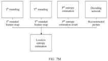
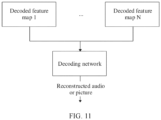
- the method further includes: using at least one of the rounded feature maps as input of a decoding network of the to-be-encoded audio or picture, and enabling the at least one of the rounded feature maps to pass through the decoding network to obtain a reconstructed audio or picture of the to-be-encoded audio or picture; calculating a difference between corresponding samples of the to-be-encoded audio or picture and the reconstructed audio or picture to obtain a residual picture of the to-be-encoded audio or picture; and obtaining probability estimation of lossless entropy estimation of a to-be-decoded audio or picture based on at least one of the following three types of information:
- any one of the encoding networks is one or more convolutional networks.
- a probability estimation result of r th entropy estimation is output as mean and variance information of an r th rounded feature map.
- the method further includes: before the rounding the first output feature map to obtain a first rounded feature map of the to-be-encoded audio or picture, the method further includes: subtracting a pixel value of a sample in the first output feature map and a mean output by the first entropy estimation to obtain a first offset feature map; and the rounding the first output feature map to obtain a first rounded feature map of the to-be-encoded audio or picture includes: rounding the first offset feature map to obtain the first rounded feature map of the to-be-encoded audio or picture.
- picture compression method may be used in a training stage of a neural network, or may be used in an inference stage of a neural network. This is not specifically limited in this application.
- the to-be-encoded audio or picture is transformed to feature space through an operation on the encoding network, and features of different layers, such as layers 1, 2, ..., and n or several layers thereof, in the feature space are extracted from a plurality of output feature maps corresponding to a plurality of encoding networks for compression. Characteristic frequencies of the layers 1, 2, ..., and n sequentially decrease.
- a quantity of feature layers used for compression is variable, and a quantity of feature channels at each layer is variable, to achieve a dynamic compression adjustment capability.
- an audio or picture decoding method including: obtaining a first to-be-decoded bitstream of a to-be-decoded audio or picture; obtaining a second to-be-decoded bitstream of the to-be-decoded audio or picture; performing entropy decoding on the second decoded bitstream of the decoded picture based on a probability estimation result of second entropy estimation of the to-be-decoded audio or picture to obtain a second decoded feature map of the to-be-decoded audio or picture; performing probability estimation of first entropy estimation based on the second feature map and/or the probability estimation result of the second entropy estimation to obtain a probability estimation result of the first entropy estimation; performing entropy decoding on the first decoded bitstream based on the probability estimation result of the first entropy estimation to obtain a first decoded feature map of the to-be-decoded audio or picture; and outputting a reconstructed audio
- probability estimation of the first entropy estimation is performed based on the second decoded feature map and/or the probability estimation result of the second entropy estimation, so that signal correlation between different layers in feature space is utilized. In this way, picture compression performance can be improved.
- entropy estimation is performed during decoding to estimate a probability of each point in a decoded feature map, so as to estimate a compression bit rate of a model.
- an entropy decoding scheme includes but is not limited to a variable-length decoding scheme and an arithmetic decoding scheme.
- the variable-length decoding scheme may include exponential Golomb decoding (Exponential Golomb Codes) and context-adaptive variable-length decoding (CAVLC).
- the arithmetic decoding scheme may include context-adaptive binary arithmetic decoding (CABAC).
- the method further includes: obtaining a third to-be-decoded bitstream of the to-be-decoded audio or picture; performing entropy decoding on the third to-be-decoded bitstream based on a probability estimation result of third entropy estimation of the to-be-decoded audio or picture to obtain a third decoded feature map of the to-be-decoded audio or picture; and performing probability estimation of the second entropy estimation of the to-be-decoded audio or picture based on the third decoded feature map and/or the probability estimation result of the third entropy estimation.
- the outputting a reconstructed audio or picture of the to-be-decoded audio or picture specifically includes:
- the decoding network outputs the reconstructed audio or picture of the to-be-decoded audio or picture by using at least one of the first decoded feature map, the second decoded feature map, and the third decoded feature map as input of the decoding network.
- probability estimation of the second entropy estimation is performed on the to-be-decoded audio or picture based on the third decoded feature map and/or the probability estimation result of the third entropy estimation.
- the method further includes: obtaining an m th to-be-decoded bitstream of the to-be-decoded audio or picture; and performing entropy decoding on the m th to-be-decoded bitstream based on a probability estimation result of m th entropy estimation of the to-be-decoded audio or picture to obtain an m th decoded feature map of the to-be-decoded audio or picture, where m is an integer greater than 3.
- the m th decoded feature map is input information of t th entropy estimation, where t is an integer less than or equal to m.
- the method further includes: obtaining a to-be-losslessly-decoded bitstream of the to-be-decoded audio or picture, and obtaining a probability estimation result of lossless entropy estimation of a to-be-decoded audio or picture based on at least one of the following three types of information:
- the method further includes: when the first decoded feature map is input of the decoding network, adding up a pixel value of a sample in the first decoded feature map and a mean output by the first entropy estimation to obtain the first decoded feature map.
- picture compression method may be used in a training stage of a neural network, or may be used in an inference stage of a neural network. This is not specifically limited in this application.
- a hierarchical decoding scheme is used. Therefore, feature information of different frequency components is extracted from different layers, so that entropy decoding at the different layers is performed in a more targeted and effective manner. This helps improve signal compression and encoding performance. In addition, correlation between inter-layer feature signals is utilized. This also facilitates implementation of entropy estimation. Based on these two factors, compression quality can be ensured at a low bit rate, that is, when reconstruction and output are performed by using only a few hierarchical decoded features. Similarly, based on these two factors, compression quality can be further improved to break through an AE limit at a high bit rate, that is, when reconstruction and output are performed by using more hierarchical decoded features.
- a hierarchical structure is used, so that the hierarchical decoding scheme can be used according to an actual requirement.
- shallow output of the decoding network is used, a quantity of network layers in the decoding network that are required for obtaining decoded features is smaller, so that computing power and run-time of the model are reduced.
- an audio or picture compression processing apparatus including:
- the encoding network module For further functions implemented by the encoding network module, the rounding module, the entropy estimation network module, the entropy encoding/decoding module, and the decoding network module, refer to any one of the first aspect, the second aspect, or the implementations of the first aspect or the second aspect. Details are not described herein again.
- this application provides an encoder, including a processing circuit, configured to perform the method according to any one of the first aspect or the implementations of the first aspect.
- this application provides a decoder, including a processing circuit, configured to perform the method according to any one of the second aspect or the implementations of the second aspect.
- this application provides a computer program product, including program code.
- the program code When being executed on a computer or a processor, the program code is used for performing the method according to any one of the first aspect or the implementations of the first aspect, or any one of the second aspect or the implementations of the second aspect.
- this application provides an encoder, including: one or more processors; and a non-transitory computer-readable storage medium, coupled to the processor and storing a program to be executed by the processor, where when the program is executed by the processor, the decoder is enabled to perform the method according to any one of the first aspect or the implementations of the first aspect.
- this application provides a decoder, including: one or more processors; and a non-transitory computer-readable storage medium, coupled to the processor and storing a program to be executed by the processor, where when the program is executed by the processor, the encoder is enabled to perform the method according to any one of the second aspect or the implementations of the second aspect.
- this application provides a non-transitory computer-readable storage medium, including program code.
- the program code When being executed by a computer device, the program code is used for performing the method according to any one of the first aspect or the implementations of the first aspect, or any one of the second aspect or the implementations of the second aspect.
- the present invention relates to an encoding apparatus that has a function of implementing the behavior in the method embodiment according to any one of the first aspect or the implementations of the first aspect.
- the function may be implemented by hardware, or may be implemented by hardware executing corresponding software.
- the hardware or the software includes one or more modules corresponding to the function.
- the encoding apparatus includes: an encoding network module, configured to: transform a raw picture into feature space through a multilayer convolution operation, and extract features of different layers, such as layers 1, 2, ..., and n or several layers thereof, in the feature space for compression, where characteristic frequencies of the layers 1, 2, ..., and n sequentially decrease, a quantity of feature layers used for compression is variable, and a quantity of feature channels at each layer is variable, to achieve a dynamic compression adjustment capability; a rounding module, configured to round an output feature to an integer for subsequent encoding; an entropy estimation network module, configured to estimate a probability of each point in a rounded feature map obtained through rounding, so as to estimate a compression bit rate of a model; and an entropy encoding module, configured to perform entropy encoding on the rounded feature map based on probability distribution obtained by an entropy estimation model, to reduce encoding redundancy of the output feature and further reduce an amount of data transmitted during picture compression.
- the present invention relates to a decoding apparatus that has a function of implementing the behavior in the method embodiment according to any one of the second aspect or the implementations of the second aspect.
- the function may be implemented by hardware, or may be implemented by hardware executing corresponding software.
- the hardware or the software includes one or more modules corresponding to the function.
- the decoding apparatus includes: an entropy estimation network module, configured to estimate a probability of each point in a decoded feature map, so as to estimate a compression bit rate of a model; an entropy decoding module, configured to perform entropy decoding on a to-be-decoded bitstream based on probability distribution obtained by an entropy estimation model, to obtain a decoded feature map, where this reduces encoding redundancy of an output feature, and further reduces an amount of data transmitted during picture compression; and a decoding network module, configured to perform inverse transformation on a compressed feature to parse the decoded feature map into an audio or picture.
- These modules may perform corresponding functions in the method example according to any one of the second aspect or the implementations of the second aspect. For details, refer to detailed descriptions in the method example. Details are not described herein again.
- a problem of high computing power occurs.
- transmission of feature signals at different layers (different feature layers) in feature space is added, and correlation between feature signals at different layers is utilized. This improves encoding quality and breaks through an AE limit.
- An encoding or decoding network corresponding to a feature layer with a high feature frequency has low computing power, so that complexity is reduced.
- a quantity of layers and channels for compressing features can be adjusted, to be compatible with a current multi-bit-rate model, and implement a plurality of bit rates in a single model.
- At least one (item) means one or more, and "a plurality of” means two or more.
- the term “and/or” describes an association relationship between associated objects, and represents that three relationships may exist.
- a and/or B may represent the following three cases: Only A exists, only B exists, and both A and B exist, where A and B may be singular or plural.
- the character “/” usually indicates an "or” relationship between the associated objects.
- At least one of the following items” or a similar expression thereof indicates any combination of the items, including any combination of one or more of the items.
- At least one of a, b, or c may indicate a, b, c, "a and b", “a and c", “b and c", or "a, b, and c", where a, b, and c may be singular or plural.
- Embodiments of this application provide an AI-based audio/video or picture compression technology, and in particular, provide a neural network-based audio/video or picture compression technology, and specifically, provide an end-to-end audio or picture coding system.
- Picture coding includes two parts: picture encoding and picture decoding, where a video includes a plurality of pictures, and is a representation of consecutive pictures.
- Audio coding includes two parts: audio encoding and audio decoding. Audio or picture encoding is performed on a source side, and usually includes: processing (for example, compressing) a raw video picture to reduce an amount of data required for representing the audio or video picture (for more efficient storage and/or transmission).
- Audio or picture decoding is performed on a destination side, and usually includes: performing inverse processing relative to an encoder, to reconstruct an audio or a picture.
- "Coding" of an audio or a picture in embodiments should be understood as “encoding” or “decoding” of the audio or the picture.
- An encoding part and a decoding part are also collectively referred to as codec (encoding and decoding, CODEC).
- a raw audio or picture can be reconstructed.
- a reconstructed audio or picture has same quality as the raw audio or picture (assuming that no transmission loss or other data loss occurs during storage or transmission).
- further compression is performed through quantization or the like, to reduce an amount of data required for representing an audio or a video picture, and the audio or the video picture cannot be fully reconstructed on a decoder side.
- quality of a reconstructed audio or video picture is poorer than that of a raw audio or video picture.
- Embodiments of this application relate to massive application of a neural network. Therefore, for ease of understanding, the following first describes related terms and concepts of the neural network that may be used in embodiments of this application.
- a neural network may include neurons.
- the neuron may be an operation unit that uses xs and an intercept of 1 as input.
- f is an activation function (activation function) of the neuron, and is used to introduce a nonlinear feature into the neural network, to convert an input signal in the neuron into an output signal.
- the output signal of the activation function may be used as input of a next convolutional layer, and the activation function may be a sigmoid function.
- the neural network is a network obtained by connecting a plurality of individual neurons. To be specific, output of a neuron may be input of another neuron. Input of each neuron may be connected to a local receptive field of a previous layer, to extract a feature of the local receptive field.
- the local receptive field may be a region including several neurons.
- a deep neural network also referred to as a multilayer neural network
- DNN deep neural network
- the DNN is divided based on locations of different layers, and a neural network in the DNN may be divided into three types: an input layer, a hidden layer, and an output layer.
- a first layer is the input layer
- a last layer is the output layer
- intermediate layers are all hidden layers. Layers are fully connected. To be specific, any neuron at an i th layer is definitely connected to any neuron at an (i + 1) t'h layer.
- a linear coefficient from a 4 th neuron at a second layer to a 2 nd neuron at a third layer is defined as W 24 3 .
- the superscript 3 indicates a layer at which the coefficient W is located, and the subscript corresponds to an output third-layer index 2 and an input second-layer index 4.
- a coefficient from a k th neuron at an (L - 1) th layer to a j th neuron at an L th layer is defined as W jk L .
- the input layer does not have the W parameter.
- a larger quantity of hidden layers enable the network to describe a complex case in the real world. Theoretically, a model with more parameters has higher complexity and a larger "capacity", and can perform a more complex learning task.
- Training of the deep neural network is a process of learning a weight matrix, and a final objective of the training is to obtain weight matrices (weight matrices including vectors W of many layers) of all layers of a trained deep neural network.
- a convolutional neural network (convolutional neuron network, CNN) is a deep neural network with a convolutional structure.
- the convolutional neural network includes a feature extractor that includes a convolutional layer and a sampling sublayer, and the feature extractor may be considered as a filter.
- the convolutional layer is a neuron layer, in the convolutional neural network, at which convolution is performed on an input signal.
- one neuron may be connected only to some neurons at adjacent layers.
- One convolutional layer usually includes several feature planes, and each feature plane may include some neurons arranged in a rectangular shape. Neurons at one feature plane share a weight, and the shared weight herein is a convolution kernel.
- the weight sharing may be understood as that a manner of extracting picture information is irrelevant to a location.
- the convolution kernel may be initialized in a form of a matrix with a random size. During training of the convolutional neural network, the convolution kernel may obtain an appropriate weight through learning. In addition, direct benefits of the weight sharing lie in that connections between layers of the convolutional neural network are reduced, and an overfitting risk is also reduced.
- a recurrent neural network (recurrent neural network, RNN) is used for processing sequence data.
- RNN recurrent neural network
- a conventional neural network model from an input layer to a hidden layer and then to an output layer, the layers are fully connected, but nodes at each layer are not connected.
- This common neural network helps resolve many problems, but is still incapable of resolving many other problems. For example, if a next word in a sentence needs to be predicted, a preceding word usually needs to be used because adjacent words in a sentence are not independent of each other.
- a reason why the RNN is referred to as the recurrent neural network is that current output of a sequence is related to previous output.
- a specific representation form is as follows: The network memorizes previous information and applies the previous information to calculation of current output.
- nodes at the hidden layer are connected to each other, and input of the hidden layer not only includes output of the input layer, but also includes output of the hidden layer at a previous moment.
- the RNN can process sequence data of any length. Training for the RNN is the same as training for a conventional CNN or DNN.
- the RNN is intended to make a machine capable of memorizing like a human. Therefore, output of the RNN needs to depend on current input information and historical memorized information.
- a current predicted value of the network may be compared with an actually expected target value, and then a weight vector of each layer of the neural network is updated based on a difference between the two values (certainly, there is usually an initialization process before a first update, to be specific, a parameter is preconfigured for each layer of the deep neural network). For example, if the predicted value of the network is large, the weight vector is adjusted to reduce the predicted value, until the deep neural network can obtain, through prediction, the actually expected target value or a value quite close to the actually expected target value.
- a difference between a predicted value and a target value needs to be predefined.
- This is a loss function (loss function) or an objective function (objective function).
- the loss function and the objective function are important equations for measuring a difference between a predicted value and a target value.
- the loss function is used as an example. A larger output value (loss) of the loss function indicates a greater difference. Therefore, the training of the deep neural network is a process of minimizing the loss.
- an error back propagation (back propagation, BP) algorithm may be used to correct a value of a parameter in an initial neural network model, so that reconstruction error loss of the neural network model becomes increasingly small.
- an input signal is transferred forward until error loss occurs at output, and the parameter in the initial neural network model is updated based on back propagation error loss information, to make the error loss converge.
- the back propagation algorithm is an error-loss-centered back propagation motion intended to obtain an optimal parameter, for example, a weight matrix, of the neural network model.
- a generative adversarial network (generative adversarial network, GAN) is a deep learning model.
- the model includes at least two modules.
- One module is a generative model (Generative Model), and the other module is a discriminative model (Discriminative Model). Learning is performed through a game between the two modules, to generate better output.
- Both the generative model and the discriminative model may be neural networks, and may be specifically deep neural networks or convolutional neural networks.
- a basic principle of the GAN is as follows: A GAN for generating an image is used as an example. It is assumed that there are two networks: G (Generator) and D (Discriminator). G is a network for generating an image.
- G receives random noise z, and generates an image based on the noise, where the image is denoted as G(z).
- D is a discriminative network for determining whether an image is "real".
- An input parameter of D is x, where x indicates an image.
- Output D(x) indicates a probability that x is a real image. If a value of D(x) is 1, it indicates that the image is 100% a real image. If the value of D(x) is 0, it indicates that the image cannot be a real image.
- an objective of the generative network G is to generate an image that is as real as possible to deceive the discriminative network D, and an objective of the discriminative network D is to distinguish between an image generated by G and a real image.
- G and D constitute a dynamic "game” process, namely, an "adversarial” process in the "generative adversarial network”.
- FIG. 1A is a schematic block diagram of an example decoding system 10, for example, an audio/video or picture decoding system 10 (or referred to as a decoding system 10) capable of using technologies of this application.
- a video encoder 20 (or referred to as an encoder 20) and an audio/video or picture decoder 30 (or referred to as a decoder 30) in the audio/video or picture decoding system 10 represent devices capable of performing technologies based on examples described in this application, or the like.
- the decoding system 10 includes a source device 12.
- the source device 12 is configured to provide encoded audio or picture data 21, such as an encoded audio or picture, for a destination device 14 configured to decode the encoded audio or picture data 21.
- the source device 12 includes the encoder 20, and in addition, may optionally include an audio or picture source 16, a pre-processor (or a pre-processing unit) 18 such as an audio or picture pre-processor, and a communication interface (or a communication unit) 22.
- a pre-processor or a pre-processing unit 18 such as an audio or picture pre-processor
- a communication interface or a communication unit 22.
- the audio or picture source 16 may include or may be any type of audio or picture capture device for capturing a real-world picture or the like, and/or any type of picture generation device, for example, a computer graphics processing unit for generating a computer animated picture, or any type of device for obtaining and/or providing a real-world picture or a computer generated picture (for example, screen content, a virtual reality (virtual reality, VR) picture, and/or any combination thereof (for example, an augmented reality (augmented reality, AR) picture)).
- the audio or picture source may be any type of internal memory or memory for storing any audio or picture in the foregoing pictures.
- an audio or picture (or picture data) 17 may also be referred to as a raw audio or picture (or raw picture data) 17.
- the pre-processor 18 is configured to receive the (raw) audio or picture data 17 and pre-process the audio or picture data 17 to obtain a pre-processed picture (or pre-processed picture data) 19.
- the pre-processing performed by the pre-processor 18 may include trimming, color format conversion (for example, conversion from RGB to YCbCr), color correction, or denoising. It can be understood that the pre-processing unit 18 may be an optional component.
- the audio/video or picture encoder (or the encoder) 20 is configured to receive the pre-processed audio or picture data 19, and provide the encoded audio or picture data 21 (this is further described below based on FIG. 2 and the like).
- the communication interface 22 of the source device 12 may be configured to receive the encoded audio or picture data 21, and send the encoded audio or picture data 21 (or any another processed version) to another device such as the destination device 14 or any other device through a communication channel 13, for storage or direct reconstruction.
- the destination device 14 includes the decoder 30, and in addition, may optionally include a communication interface (or a communication unit) 28, a post-processor (or a post-processing unit) 32, and a display device 34.
- the communication interface 28 of the destination device 14 is configured to: directly receive the encoded audio or picture data 21 (or any further processed version) from the source device 12 or any other source device such as a storage device, where for example, the storage device is a storage device for encoded audio or picture data; and provide the encoded audio or picture data 21 for the decoder 30.
- the communication interface 22 and the communication interface 28 may be configured to send or receive the encoded audio or picture data (or encoded data) 21 through a direct communication link between the source device 12 and the destination device 14, for example, a direct wired or wireless connection, or any type of network such as a wired network, a wireless network, or any combination thereof, or any type of private network or public network or any combination thereof.
- the communication interface 22 may be configured to encapsulate the encoded audio or picture data 21 into an appropriate format such as a packet, and/or process the encoded audio or picture data through any type of transmission encoding or processing, so that processed encoded audio or picture data can be transmitted through a communication link or a communication network.
- the communication interface 28 corresponds to the communication interface 22, and for example, may be configured to receive transmitted data, and process the transmitted data through any type of corresponding transmission decoding or processing and/or decapsulation to obtain the encoded audio or picture data 21.
- the communication interface 22 and the communication interface 28 each may be configured as a unidirectional communication interface indicated by an arrow, in FIG. 1A , that corresponds to the communication channel 13 and that is directed from the source device 12 to the destination device 14, or a bidirectional communication interface, and may be configured to: send and receive messages or the like to establish a connection, determine and exchange any other information related to a communication link and/or data transmission such as transmission of encoded picture data, and the like.
- the audio/video or picture decoder (or the decoder) 30 is configured to receive the encoded audio or picture data 21, and provide decoded audio or picture data (or decoded audio or picture data) 31 (this is further described below based on FIG. 4 and the like).
- the post-processor 32 is configured to post-process the decoded audio or picture data (also referred to as reconstructed audio or picture data) 31 such as a decoded audio or picture, to obtain post-processed audio or picture data 33 such as a post-processed audio or picture.
- the post-processing performed by the post-processing unit 32 may include color format conversion (for example, conversion from YCbCr to RGB), color correction, trimming, resampling, or any other processing for generating the decoded audio or picture data 31 to be displayed by the display device 34 or the like.
- the display device 34 is configured to receive the post-processed audio or picture data 33, to display a picture to a user, a viewer, or the like.
- the display device 34 may be or include any type of player or display for representing the reconstructed audio or picture, for example, an integrated or external display or monitor.
- the display may include a liquid crystal display (liquid crystal display, LCD), an organic light emitting diode (organic light emitting diode, OLED) display, a plasma display, a projector, a micro-LED display, a liquid crystal on silicon (liquid crystal on silicon, LCoS) display, a digital light processor (digital light processor, DLP), or any other type of display.
- the decoding system 10 further includes a training engine 25.
- the training engine 25 is configured to train the encoder 20 or the decoder 30 for processing (for example, processing an input audio, picture, picture region, or picture block to generate a predicted value of the input audio, picture, picture region, or picture block).
- Training data may be stored in a database (not shown), and the training engine 25 obtains a target model (which may be, for example, a network used for audio or picture encoding or decoding) through training based on the training data.
- a source of the training data is not limited in this embodiment of this application.
- the training data may be obtained from a cloud or another place for model training.
- FIG. 1A shows the source device 12 and the destination device 14 as separate devices
- device embodiments may alternatively include both the source device 12 and the destination device 14, or may include functions of both the source device 12 and the destination device 14, that is, may include both the source device 12 or a corresponding function and the destination device 14 or a corresponding function.
- the source device 12 or the corresponding function and the destination device 14 or the corresponding function may be implemented by using same hardware and/or software, separate hardware and/or software, or any combination thereof.
- the encoder 20 for example, the audio/video or picture encoder 20
- the decoder 30 for example, the audio/video or picture decoder 30
- both the encoder 20 and the decoder 30 may be implemented by using a processing circuit shown in FIG. 1B , for example, one or more microprocessors, a digital signal processor (digital signal processor, DSP), an application-specific integrated circuit (application-specific integrated circuit, ASIC), a field-programmable gate array (field-programmable gate array, FPGA), discrete logic, hardware, a dedicated processor for audio/video or picture encoding, or any combination thereof.
- the encoder 20 may be implemented by using a processing circuit 46, to include various modules described with reference to an encoder 20 in FIG.
- the decoder 30 may be implemented by using a processing circuit 46, to include various modules described with reference to a decoder 30 in FIG. 4 and/or any other decoder system or subsystem described in this specification.
- the processing circuit 46 may be configured to perform various operations described below. As shown in FIG. 7 , if some technologies are implemented in software, a device may store software instructions in a suitable non-transitory computer-readable storage medium, and execute the instructions in hardware through one or more processors, to perform technologies of the present invention.
- One of the audio/video or picture encoder 20 and the audio/video or picture decoder 30 may be integrated in a single device as a part of a combined encoder/decoder (encoder/decoder, CODEC), as shown in FIG. 1B .
- encoder/decoder CODEC
- the source device 12 and the destination device 14 may include any one of a variety of devices, including any type of handheld device or stationary device, for example, a notebook computer, a laptop computer, a mobile phone, a smartphone, a tablet or tablet computer, a camera, a desktop computer, a set-top box, a television, a display device, a digital media player, a video gaming console, a video streaming device (for example, a content business server or a content delivery server), a broadcast receiver device, or a broadcast transmitter device, and may not use an operating system or may use any type of operating system.
- the source device 12 and the destination device 14 may be equipped with components for wireless communication. Therefore, the source device 12 and the destination device 14 may be wireless communication devices.
- the audio/video or picture decoding system 10 shown in FIG. 1A is merely an example. Technologies provided in this application are applicable to audio/video or picture encoding settings (for example, audio/video or picture encoding, or video or picture decoding). These settings do not necessarily include any data communication between an encoding device and a decoding device. In another example, data is retrieved from a local memory and is transmitted through a network. An audio/video or picture encoding device may encode data and store encoded data in a memory, and/or an audio/video or picture decoding device may retrieve the data from the memory and decode the data. In some examples, encoding and decoding are performed by devices that do not communicate with each other but only encode data to a memory and/or retrieve data from a memory and decode the data.
- FIG. 1B is a schematic diagram of an example of a video or picture decoding system 40 that includes the audio/video or picture encoder 20 in FIG. 1A and/or the audio/video or picture decoder 30 in FIG. 1B according to an example embodiment.
- the audio/video or picture decoding system 40 may include an imaging device 41, an audio/video or picture encoder 20, an audio/video or picture decoder 30 (and/or an audio/video or picture encoder/decoder implemented by using the processing circuit 46), an antenna 42, one or more processors 43, one or more internal memories 44, and/or a display device 45.
- the imaging device 41, the antenna 42, the processing circuit 46, the audio/video or picture encoder 20, the audio/video or picture decoder 30, the processor 43, the internal memory 44, and/or the display device 45 can communicate with each other.
- the audio/video or picture decoding system 40 may include only the audio/video or picture encoder 20 or only the audio/video or picture decoder 30.
- the antenna 42 may be configured to transmit or receive an encoded bitstream of audio/video or picture data.
- the display device 45 may be configured to display audio/video or picture data.
- the processing circuit 46 may include application-specific integrated circuit (application-specific integrated circuit, ASIC) logic, a graphics processing unit, a general-purpose processor, or the like.
- the audio/video or picture decoding system 40 may also include an optional processor 43.
- the optional processor 43 may include application-specific integrated circuit (application-specific integrated circuit, ASIC) logic, a graphics processing unit, a general-purpose processor, or the like.
- the internal memory 44 may be any type of memory, for example, a volatile memory (for example, a static random access memory (static random access memory, SRAM) or a dynamic random access memory (dynamic random access memory, DRAM)), or a nonvolatile memory (for example, a flash memory).
- a volatile memory for example, a static random access memory (static random access memory, SRAM) or a dynamic random access memory (dynamic random access memory, DRAM)
- a nonvolatile memory for example, a flash memory.
- the internal memory 44 may be implemented by using a cache memory.
- the processing circuit 46 may include a memory (for example, a cache) for implementing a picture buffer, or the like.
- the audio/video or picture encoder 20 implemented by using a logic circuit may include an audio or picture buffer (which is implemented by using, for example, the processing circuit 46 or the internal memory 44) and an audio or graphics processing unit (which is implemented by using, for example, the processing circuit 46).
- the audio or graphics processing unit may be communicatively coupled to the picture buffer.
- the audio or graphics processing unit may include the audio/video or picture encoder 20 implemented by using the processing circuit 46, to implement various modules described with reference to FIG. 2 and/or any other encoder system or subsystem described in this specification.
- the logic circuit may be configured to perform various operations described in this specification.
- the audio/video or picture decoder 30 may be implemented by using the processing circuit 46 in a similar manner, to implement various modules described with reference to the audio/video or picture decoder 30 in FIG. 1B and/or any other decoder system or subsystem described in this specification.
- the audio/video or picture decoder 30 implemented by using a logic circuit may include an audio or picture buffer (which is implemented by using the processing circuit 46 or the internal memory 44) and an audio or graphics processing unit (which is implemented by using, for example, the processing circuit 46).
- the audio or graphics processing unit may be communicatively coupled to the picture buffer.
- the audio or graphics processing unit may include the audio/video or picture decoder 30 implemented by using the processing circuit 46, to implement various modules described with reference to FIG. 4 and/or any other decoder system or subsystem described in this specification.
- the antenna 42 may be configured to receive an encoded bitstream of audio/video or picture data.
- the encoded bitstream may include data, an indicator, an index value, mode selection data, or the like that is related to audio/video frame encoding and that is described in this specification, for example, data related to code partitioning (for example, a transform coefficient or a quantized transform coefficient, an optional indicator (as described), and/or data defining the code partitioning).
- the audio/video or picture decoding system 40 may further include the audio/video or picture decoder 30 that is coupled to the antenna 42 and that is configured to decode the encoded bitstream.
- the display device 45 is configured to display a video frame.
- the audio/video or picture decoder 30 may be configured to perform a reverse process.
- the audio/video or picture decoder 30 may be configured to receive and parse the syntax element, and correspondingly decode related video data.
- the audio/video or picture encoder 20 may perform entropy encoding on the syntax element to obtain an encoded bitstream.
- the audio/video or picture decoder 30 may parse the syntax element, and correspondingly decode related audio/video or picture data.
- FIG. 1C is a schematic diagram of an audio/video or picture decoding device 400 according to an embodiment of the present invention.
- the audio/video or picture decoding device 400 is suitable for implementing disclosed embodiments described in this specification.
- the audio/video or picture decoding device 400 may be a decoder, for example, the audio/video or picture decoder 30 in FIG. 1A , or may be an encoder, for example, the audio/video or picture encoder 20 in FIG. 1A .
- the audio/video or picture decoding device 400 includes: an ingress port 410 (or an input port 410) and a receiver unit (receiver unit, Rx) 420 for receiving data; a processor, a logic unit, or a central processing unit (central processing unit, CPU) 430 for processing the data, for example, the processor 430 may be a neural network processing unit 430; a transmitter unit (transmitter unit, Tx) 440 and an egress port 450 (or an output port 450) for transmitting the data; and a memory 460 for storing the data.
- the audio/video or picture decoding device 400 may further include an optical-to-electrical (optical-to-electrical, OE) component and an electrical-to-optical (electrical-to-optical, EO) component that are coupled to the ingress port 410, the receiver unit 420, the transmitter unit 440 and the egress port 450 and that serve as an egress or an ingress of an optical signal or an electrical signal.
- optical-to-electrical optical-to-electrical, OE
- EO electrical-to-optical
- the processor 430 is implemented by using hardware and software.
- the processor 430 may be implemented as one or more processor chips, cores (for example, a multi-core processor), FPGAs, ASICs, or DSPs.
- the processor 430 communicates with the ingress port 410, the receiver unit 420, the transmitter unit 440, the egress port 450, and the memory 460.
- the processor 430 includes a decoding module 470 (for example, a neural network NN-based decoding module 470).
- the decoding module 470 implements the foregoing disclosed embodiments. For example, the decoding module 470 performs, processes, prepares, or provides various encoding operations.
- the decoding module 470 provides a substantial improvement on functions of the audio/video or picture decoding device 400, and affects switching of the audio/video or picture decoding device 400 between different states.
- the decoding module 470 is implemented by using instructions that are stored in the memory 460 and that are to be executed by the processor 430.
- the memory 460 includes one or more magnetic disks, magnetic tapes, or solid-state drives, and may serve as an overflow data storage device, to store a program when the program is selected for execution, and to store instructions and data that are read during program execution.
- the memory 460 may be volatile and/or nonvolatile, and may be a read-only memory (read-only memory, ROM), a random access memory (random access memory, RAM), a ternary content-addressable memory (ternary content-addressable memory, TCAM), and/or a static random access memory (static random access memory, SRAM).
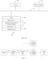
- FIG. 1D is a simplified block diagram of an apparatus 500 according to an example embodiment.
- the apparatus 500 may serve as either or both of the source device 12 and the destination device 14 in FIG. 1A .
- a processor 502 in the apparatus 500 may be a central processing unit.
- the processor 502 may be any other type of device or a plurality of devices that currently exist or are to be developed in the future and that are capable of manipulating or processing information.
- disclosed implementations may be implemented by a single processor such as the processor 502 shown in the figure, a speed and efficiency are higher when more than one processor is used.
- a memory 504 in the apparatus 500 may be a read-only memory (ROM) device or a random access memory (RAM) device. Any other suitable type of storage device may serve as the memory 504.
- the memory 504 may include code and data 506 that is accessed by the processor 502 through a bus 512.
- the memory 504 may further include an operating system 508 and an application program 510.
- the application program 510 includes at least one program that enables the processor 502 to perform a method described in this specification.
- the application program 510 may include applications 1 to N, and may further include an audio/video or picture decoding application for performing the method described in this specification.
- the apparatus 500 may further include one or more output devices, such as a display 518.
- the display 518 may be a touch-sensitive display obtained by combining a display with a touch-sensitive element capable of sensing touch input.
- the display 518 may be coupled to the processor 502 through the bus 512.
- bus 512 in the apparatus 500 is described as a single bus in this specification, the bus 512 may include a plurality of buses.
- an auxiliary memory may be directly coupled to another component of the apparatus 500 or may be accessed through a network, and may include a single integrated unit such as a memory card, or a plurality of units such as a plurality of memory cards. Therefore, the apparatus 500 may have a variety of configurations.
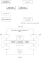
- FIG. 2 is a schematic block diagram of an example of an audio/video or picture encoder 20 for implementing technologies of this application.
- the audio/video or picture encoder 20 includes an input end (or an input interface) 202, an encoding network 204, rounding 206, entropy encoding 208, entropy estimation 210, and an output end (or an output interface) 212.
- the audio/video encoder 20 shown in FIG. 2 may also be referred to as an end-to-end audio or picture encoder or an audio or picture encoder based on an end-to-end audio or picture codec.
- the encoder 20 may be configured to receive an audio or picture (or audio or picture data) 17 through the input end 202 or the like, for example, an audio or picture that forms an audio/video or video sequence.
- the received audio or picture, or audio or picture data may alternatively be a pre-processed audio or picture (or pre-processed audio or picture data) 19.
- the audio or picture 17 is used in the following descriptions.
- the audio or picture 17 may also be referred to as a current audio or picture or audio or a to-be-encoded audio or picture (especially when the current audio or picture is distinguished from another audio in audio/video encoding, the another audio or picture, for example, in a same audio or video sequence, also includes a previous encoded audio or picture and/or decoded audio or picture in an audio or video sequence of the current audio or picture).
- a (digital) picture is or may be considered as a two-dimensional array or matrix including samples with intensity values.
- a sample in an array may also be referred to as a pixel (pixel or pel) (which is short for a picture element).
- a quantity of samples of an array or a picture in a horizontal direction and a vertical direction (or axes) defines a size and/or a resolution of the picture.
- Three color components are usually used to represent a color.
- a picture may be represented as or include three sample arrays. In an RBG format or color space, a picture includes corresponding red, green and blue sample arrays.
- each pixel is usually represented in a luminance/chrominance format or as color space, for example, YCbCr, which includes a luminance component (sometimes also denoted as L) indicated by Y and two chrominance components indicated by Cb and Cr.
- the luminance (luma) component Y represents luminance or grayscale intensity (for example, the luminance and the grayscale intensity are the same in a grayscale picture)
- the two chrominance (chrominance, chroma for short) components Cb and Cr represent chrominance or color information components.
- a picture in a YCbCr format includes a luminance sample array of luminance sample values (Y) and two chrominance sample arrays of chrominance values (Cb and Cr).
- a picture in an RGB format may be converted or transformed into a YCbCr format, and vice versa. This process is also referred to as color transformation or conversion. If a picture is in black and white, the picture may include only a luminance sample array.
- the picture may be, for example, a luminance sample array in a monochrome format, or a luminance sample array and two corresponding chrominance sample arrays in a color format of 4:2:0, 4:2:2, or 4:4:4.
- an embodiment of the video or picture encoder 20 may include a picture partitioning unit (not shown in FIG. 1A or FIG. 1B ), configured to partition the picture 17 into a plurality of (usually, non-overlapping) picture blocks 203. These blocks may also be referred to as root blocks, macro blocks (H.264/AVC), coding tree blocks (Coding Tree Block, CTB) or coding tree units (Coding Tree Unit, CTU) in the H.265/HEVC and VVC standards.
- the partitioning unit may be configured to use a same block size and use a corresponding grid that defines the block size for all pictures in a video sequence, or change a block size between pictures, picture subsets, or picture groups, and partition each picture into corresponding blocks.
- the video or picture encoder may be configured to directly receive the block 203 of the picture 17, for example, one or more or all blocks that constitute the picture 17.
- the picture block 203 may also be referred to as a current picture block or a to-be-encoded picture block.
- the picture block 203 is also or may also be considered as a two-dimensional array or matrix including samples with intensity values (sample values).
- the picture block 203 is smaller than the picture 17.
- the block 203 may include one sample array (for example, a luminance array in the case of a monochrome picture 17, or a luminance array or a chrominance array in the case of a color picture), three sample arrays (for example, one luminance array and two chrominance arrays in the case of a color picture 17), or any other quantity and/or types of arrays based on a used color format.
- a quantity of samples of the block 203 in a horizontal direction and a vertical direction (or axes) defines a size of the block 203.
- the block may be an M ⁇ N (M columns ⁇ N rows) sample array, or an M ⁇ N transform coefficient array, or the like.
- the audio/video or picture encoder 20 shown in FIG. 1A , FIG. 1B , or FIG. 2 is configured to encode the picture 17 per block, for example, perform encoding, rounding, and entropy encoding on each block 203.
- the audio/video or picture encoder 20 shown in FIG. 1A , FIG. 1B , or FIG. 2 is configured to encode the picture 17, for example, perform encoding, quantization, and entropy encoding on the picture 17.
- the audio/video or picture encoder 20 shown in FIG. 1A , FIG. 1B , or FIG. 2 is configured to encode the audio data 17, for example, perform encoding, quantization, and entropy encoding on the audio data 17.
- the audio/video or picture encoder 20 shown in FIG. 1A , FIG. 1B , or FIG. 2 may be further configured to partition an encoded picture by slice (also referred to as a video slice), where the picture may be partitioned or encoded into one or more (usually, non-overlapping) slices.
- Each slice may include one or more blocks (for example, a coding tree unit CTU) or one or more block groups (for example, a tile (tile) in the H.265/HEVC/VVC standards and a subpicture (subpicture) in the VVC standard).
- the audio/video or picture encoder 20 shown in FIG. 1A , FIG. 1B , or FIG. 2 may be further configured to partition an audio by segment, where the audio may be partitioned or encoded into one or more (usually, non-overlapping) segments.
- the audio/video or picture encoder 20 shown in FIG. 1A , FIG. 1B , or FIG. 2 may be further configured to partition and/or encode a picture by slice/tile group (also referred to as a video tile group) and/or by tile (also referred to as a video tile), where the picture may be partitioned or encoded into one or more (usually, non-overlapping) slice/tile groups.
- Each slice/tile group may include one or more blocks (for example, a CTU), one or more tiles, or the like.
- Each tile may be in a rectangular shape or the like, and may include one or more complete or partial blocks (for example, a CTU).
- the encoding network unit 204 is configured to obtain an output feature map 205 of each feature layer through an encoding network based on input data 203.
- the encoding network unit outputs at least two output feature maps 205 corresponding to two or more feature layers.
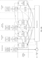
- the encoding network unit is shown in FIG. 3A .
- the encoding network unit includes K encoding sub-networks, and each encoding sub-network corresponds to a feature layer and a corresponding output feature map.
- K output feature maps are output, where K ⁇ 2.
- input of the encoding network is a to-be-encoded audio or picture or a to-be-encoded audio segment or picture block.
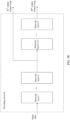
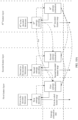
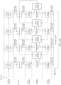
- FIG. 3B an input/output structure of the encoding network in the encoding network 204 is shown in FIG. 3B .
- the encoding network unit includes T network layers, where M, L, T, and K are positive integers. Both an M th output feature map and a K th output feature map are output of the encoding network.
- the K th output feature map output by the encoding network is output after a network layer L in the encoding network unit, and the M th output feature map is output after a network layer T.
- a plurality of output feature maps may be output after locations of different network layers in the encoding network unit. This is not limited herein.
- Any network layer in FIG. 3B may be a convolutional layer, a normalization layer, a nonlinear activation layer, or the like.
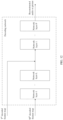
- structures of encoding sub-networks corresponding to FIG. 3A in the encoding network 204 may be the same as or different from each other, and structures of an M th encoding sub-network and an N th encoding sub-network are shown in FIG. 4 .
- a structure of a network layer 1 in the M th encoding sub-network may be different from a structure of any network layer in the N th encoding sub-network, L and P may be the same or different, and both L and P are positive integers greater than 0.
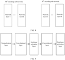
- an example of a network structure of any encoding sub-network in the encoding network 204 is shown in FIG. 5 . It can be learned that an N th encoding sub-network in the example includes five network layers, and specifically includes one normalization layer, two convolutional layers, and two nonlinear activation layers.
- the rounding unit 206 is configured to round the output feature map 205 through, for example, scalar quantization or vector quantization, to obtain a rounded feature map 207.
- the audio/video or picture encoder 20 may be configured to output a rounding parameter (quantization parameter, QP), for example, directly output the quantization parameter or output a quantization parameter encoded or compressed by an entropy encoding unit 270, so that, for example, the audio/video decoder 30 can receive and use the quantization parameter for decoding.
- a rounding parameter quantization parameter, QP
- a rounding operation is performed on all output feature maps of N feature layers, to output N rounded feature maps, where N is a positive integer greater than 1.
- an output feature map is pre-processed before rounding, including: subtracting a pixel value of a sample in the output feature map and a mean output by entropy estimation to obtain an offset feature map, and rounding the obtained offset feature map to obtain a rounded feature map.
- the entropy encoding unit 208 is configured to apply an entropy encoding algorithm or scheme (for example, a variable-length encoding (variable-length coding, VLC) scheme, a context-adaptive VLC (context-adaptive VLC, CALVC) scheme, an arithmetic encoding scheme, a binarization algorithm, context-adaptive binary arithmetic encoding (context-adaptive binary arithmetic coding, CABAC), syntax-based context-adaptive binary arithmetic encoding (syntax-based context-adaptive binary arithmetic coding, SBAC), probability interval partitioning entropy (probability interval partitioning entropy, PIPE) encoding, or another entropy encoding method or technology) to rounded feature maps of at least two feature layers, to obtain the encoded audio or picture data 21 that can be output through the output end 212 in a form of the encoded bitstream 21 or the like, so that the video
- the entropy estimation unit 210 is configured to perform probability estimation on a rounded feature map to estimate a compression bit rate of a model. Input indicated by dashed lines is optional input.
- the entropy estimation unit 210 corresponds to N entropy estimation modules corresponding to N feature layers.
- the entropy estimation unit 210 is configured to perform probability estimation on a rounded feature map to estimate a compression bit rate of a model. Input indicated by dashed lines is optional input.
- the entropy estimation unit 210 corresponds to N entropy estimation modules corresponding to N feature layers, and a lossless entropy estimation module corresponding to a residual layer.
- a P th entropy estimation result in the encoder is input of L th entropy estimation, where L and P are positive integers, and L ⁇ P.
- a plurality of entropy estimation results in the encoder are input of L th entropy estimation, and a sequence number of a feature layer corresponding to each of a plurality of entropy estimation modules is greater than L, where L is a positive integer.
- L, I, T, and K are all positive integers, L ⁇ I, L ⁇ T, and L ⁇ K.
- a P th rounded feature map in the encoder is input of L th entropy estimation, where L and P are positive integers, and L ⁇ P.
- a plurality of rounded feature maps in the encoder are input of L th entropy estimation, and a sequence number of a feature layer corresponding to each of a plurality of rounding modules is greater than L, where L is a positive integer.
- L, I, T, and K are all positive integers, L ⁇ I, L ⁇ T, and L ⁇ K.
- At least one rounded feature map and at least one entropy estimation result in the encoder are input of L th entropy estimation, where L is a positive integer.
- a sequence number of a feature layer corresponding to a rounded feature map used as input of the L th entropy estimation is greater than or equal to L, and a sequence number of a feature layer corresponding to an entropy estimation result used as input of the L th entropy estimation is greater than L.
- L, I, T, and K are all positive integers, L ⁇ I, L ⁇ T, and L ⁇ K.
- a P th entropy estimation result in the encoder is input of lossless entropy estimation, where P is a positive integer.
- a plurality of entropy estimation results in the encoder are input of lossless entropy estimation.
- I, T, and K are all positive integers.
- a P th rounded feature map in the encoder is input of lossless entropy estimation, where P is a positive integer.
- a plurality of rounded feature maps in the encoder are input of lossless entropy estimation. For example, as shown in FIG. 7I , I, T, and K are all positive integers.
- At least one rounded feature map and at least one entropy estimation result in the encoder are input of lossless entropy estimation.
- I, T, and K are all positive integers.
- At least one rounded feature map and a reconstructed audio or picture in the encoder are input of lossless entropy estimation.
- I and T are both positive integers.
- At least one entropy estimation result and a reconstructed audio or picture in the encoder are input of lossless entropy estimation.
- I and T are both positive integers.
- At least one entropy estimation result, a reconstructed audio or picture, and at least one rounded feature map in the encoder are input of lossless entropy estimation.
- I, T, and P are all positive integers.
- an entropy estimation network is a convolutional network, and the convolutional network includes a convolutional layer and a nonlinear activation layer. It can be learned that an entropy estimation network in an example in FIG. 8 includes five network layers, and specifically includes three convolutional layers and two nonlinear activation layers.
- FIG. 1A and FIG. 1B show the example audio/video or picture decoder 30 for implementing technologies of this application.
- the audio/video or picture decoder 30 is configured to receive, for example, the encoded audio or picture data 21 (for example, the encoded bitstream 21) encoded by the encoder 20, to obtain a decoded audio or picture 308.
- the encoded picture data or bitstream includes information for decoding the encoded picture data, for example, data representing a picture block of an encoded video slice (and/or a tile group or a tile) and a related syntax element.
- the decoder 30 includes an entropy estimation unit 304, an entropy decoding unit 306, and a decoding network unit 308.
- the entropy estimation unit 304 is configured to perform probability estimation on a decoded feature map. Input indicated by dashed lines is optional input.
- the entropy estimation unit 304 corresponds to N entropy estimation modules corresponding to N feature layers.
- the entropy estimation unit 304 is configured to perform probability estimation on a decoded feature map to estimate a compression bit rate of a model. Input indicated by dashed lines is optional input.
- the entropy estimation unit 304 corresponds to N entropy estimation modules corresponding to N feature layers, and a lossless entropy estimation module corresponding to a residual layer.
- a P th entropy estimation result in the decoder is input of L th entropy estimation, where L and P are positive integers, and L ⁇ P.
- a plurality of entropy estimation results in the decoder are input of L th entropy estimation, and a sequence number of a feature layer corresponding to each of a plurality of entropy estimation modules is greater than L, where L is a positive integer.
- L, I, T, and K are all positive integers, L ⁇ I, L ⁇ T, and L ⁇ K.
- a P th decoded feature map in the decoder is input of L th entropy estimation, where L and P are positive integers, and L ⁇ P.
- a plurality of decoded feature maps in the decoder are input of L th entropy estimation, and sequence numbers of feature layers corresponding to a plurality of entropy decoding modules are all greater than L, where L is a positive integer.
- At least one decoded feature map and at least one entropy estimation result in the decoder are input of L th entropy estimation, where L is a positive integer.
- a sequence number of a feature layer corresponding to a decoded feature map used as input of the L th entropy estimation is greater than or equal to L, and a sequence number of a feature layer corresponding to an entropy estimation result used as input of the L th entropy estimation is greater than L.
- a P th entropy estimation result in the decoder is input of lossless entropy estimation, where P is a positive integer.
- a plurality of entropy estimation results in the decoder are input of lossless entropy estimation.
- I, T, and K are all positive integers.
- a P th decoded feature map in the decoder is input of lossless entropy estimation, where P is a positive integer.
- a plurality of decoded feature maps in the decoder are input of lossless entropy estimation.
- At least one decoded feature map and at least one entropy estimation result in the decoder are input of lossless entropy estimation.
- At least one decoded feature map and a reconstructed audio or picture in the decoder are input of lossless entropy estimation.
- At least one entropy estimation result and a reconstructed audio or picture in the decoder are input of lossless entropy estimation.
- I and T are both positive integers.
- At least one entropy estimation result, a reconstructed audio or picture, and at least one decoded feature map in the decoder are input of lossless entropy estimation.
- entropy estimation is a convolutional network, and the convolutional network includes a convolutional layer and a nonlinear activation layer. It can be learned that an entropy estimation network in an example in FIG. 8 includes five network layers, and specifically includes three convolutional layers and two nonlinear activation layers.
- the entropy decoding unit 306 is configured to parse the bitstream 21 (or usually, the encoded picture data 21), and perform entropy decoding on the encoded audio or picture data 21 to obtain a decoded feature map 307, a decoded encoding parameter (not shown in FIG. 11 ), and/or the like.
- the entropy decoding unit 304 may be configured to apply a decoding algorithm or scheme corresponding to an encoding scheme of the entropy encoding unit 208 of the encoder 20.
- the entropy decoding unit is applied to a to-be-decoded bitstream corresponding to at least two feature layers.
- the entropy decoding unit is applied to a to-be-losslessly-decoded bitstream corresponding to a residual layer.
- the decoder 30 may be further configured to perform entropy decoding on the picture 21 or a picture block in the picture 21.
- the decoder 30 may be further configured to perform entropy decoding on the audio 21 or an audio segment in the audio 21.
- the decoding network 306 is configured to enable the decoded feature map 307 to pass through the decoding network 308 to obtain a reconstructed audio or picture 310 in a pixel domain.
- FIG. 11 is a schematic diagram of inputting N decoded feature maps to the decoding network, where N is greater than 1.
- a decoded feature map is pre-processed before being input to the decoding network, including: subtracting a pixel value of a sample in an output feature map and a mean output by entropy estimation to obtain an offset feature map, adding up a pixel value of a sample in the decoded feature map and a mean output by entropy estimation to obtain an updated decoded feature map, and then inputting the updated decoded feature map to the decoding network.
- the decoding network 306 includes P network layers, where P > L, and M, L, T, and P are all positive integers.
- a T th decoded feature map is input after a network layer L in the decoding network 306. Both the T th decoded feature map and an M th decoded feature map are input of the decoding network. It can be understood that a plurality of decoded feature maps may be input after locations of different network layers in the decoding network unit. This is not limited herein.
- Any network layer in FIG. 12 may be a convolutional layer, a normalization layer, a nonlinear activation layer, or the like.
- the decoding network 306 may include operations such as concatenation (concat), addition, and subtraction.
- structures of network layers in the decoding network 306 may be the same or different from each other.
- the decoding network in the example includes 12 network layers, and specifically includes one denormalization layer, six convolutional layers, and four nonlinear activation layers.
- m, n, and t are all positive integers.
- the decoding network outputs a decoded picture or a reconstructed audio or picture.
- a t th decoded feature map, an n th decoded feature map, and an m th decoded feature map are all input of the decoding network, where t, n, and m are integers.
- a processing result of a current step may be further processed and then output to a next step.
- an operation or processing such as a clip (clip) or shift (shift) operation or filtering, may be further performed on a processing result of the encoder unit or the decoder unit.
- the embodiments of the decoding system 10, the encoder 20, and the decoder 30 and other embodiments described in this specification may also be used for processing or coding of static pictures, to be specific, processing or coding of a single picture independent of any previous or consecutive pictures in audio/video coding. All other functions (also referred to as tools or technologies) of the audio/video encoder 20 and the audio/video decoder 30 may also be used for processing of static pictures.
- FIG. 14A shows a possible system architecture according to this application. Model operation steps are as follows.
- Step 1 Input data passes through an encoding network, and N output feature maps are output.
- Step 2 Perform a rounding operation on the N output feature maps to obtain N rounded feature maps.
- Step 3 Sequentially (in an order from an N th to a 1 st ) estimate a probability of each rounded feature map based on entropy estimation, and perform entropy encoding on the N rounded feature maps to obtain N encoded bitstreams.
- An M th rounded feature map may be input of L th entropy estimation, where L, M, and N are all positive integers, L ⁇ 1, and L ⁇ M ⁇ N.
- P th entropy estimation may be input of T th entropy estimation, where T, P, and N are all positive integers, T ⁇ 1, and T ⁇ P ⁇ N.
- Step 1 Obtain N to-be-decoded bitstreams, and sequentially (in an order from an N th to a 1 st ) perform entropy decoding based on entropy estimation to obtain N decoded feature maps.
- An M th rounded feature map may be input of L th entropy estimation, where L, M, and N are all positive integers, L ⁇ 1, and L ⁇ M ⁇ N.
- P th entropy estimation may be input of T th entropy estimation, where T, P, and N are all positive integers, T ⁇ 1, and T ⁇ P ⁇ N.
- Step 2 N output feature maps pass through a decoding network to obtain output data.
- FIG. 14B and FIG. 14C show a system architecture 700 in a possible scenario according to an embodiment of this application. Model operation steps are as follows.
- An encoding network module includes four feature layers, and extracts four output feature maps of an input picture through four encoding sub-networks, where a network depth, a quantity of feature layers, and a quantity of feature channels at each layer of each encoding network are variable, to achieve a function of dynamically changing a compression capability of a model.
- Step 2 As shown in FIG. 14B , a rounding module rounds a first to a fourth output feature maps to obtain a first to a fourth rounded feature maps, which correspond to y 1 , y 2 , y 3 , and y 4 in FIG. 14C .
- Step 3 An entropy estimation module sequentially estimates probabilities of compressed features.
- the fourth rounded feature map is input of third entropy estimation
- the third rounded feature map is input of second entropy estimation
- the second rounded feature map is input of first entropy estimation.
- a probability of the rounded feature map y 4 is estimated by using a known probability
- a probability of the rounded feature map y 3 is estimated by using the rounded feature map y 4
- a probability of y 2 is estimated by using the rounded feature map y 3
- a probability of the rounded feature map y 1 is estimated by using the rounded feature map y 2 .
- Step 4 As shown in FIG. 14B , in an order from a deep layer to a shallow layer, an entropy encoding module performs entropy encoding on the fourth rounded feature map based on a fourth entropy estimation result, performs entropy encoding on the third rounded feature map based on a third entropy estimation result, performs entropy encoding on the second rounded feature map based on a second entropy estimation result, and performs entropy encoding on the first rounded feature map based on a first entropy estimation result.
- FIG. 14B in an order from a deep layer to a shallow layer, an entropy encoding module performs entropy encoding on the fourth rounded feature map based on a fourth entropy estimation result, performs entropy encoding on the third rounded feature map based on a third entropy estimation result, performs entropy encoding on the second rounded feature map
- entropy encoding is sequentially performed on the rounded feature maps y 4 , y 3 , y 2 , and y 1 based on the probabilities of the rounded feature maps y 4 , y 3 , y 2 , and y 1 , to generate data to be transmitted through a network or stored as a local file.
- Step 1 As shown in FIG. 14B , an entropy estimation network module decodes a fourth encoded bitstream or a fourth to-be-decoded bitstream based on a fourth entropy estimation result to obtain a fourth decoded feature map. Correspondingly, as shown in FIG. 14B , a probability of y 4 is estimated based on a known probability, and an entropy decoding module obtains y 4 through decoding.
- Step 2 As shown in FIG. 14C , a third entropy estimation network decodes a third encoded bitstream or a third to-be-decoded bitstream based on the fourth decoded feature map to obtain a third decoded feature map.
- a probability of y 3 is estimated by using y 4 , and the entropy decoding module obtains y 3 through decoding.
- Step 3 As shown in FIG. 14B , a second entropy estimation network decodes a second encoded bitstream or a second to-be-decoded bitstream based on the third decoded feature map to obtain a second decoded feature map.
- a probability of y 2 is estimated by using y 3 , and the entropy decoding module obtains y 2 through decoding.
- Step 4 As shown in FIG. 14C , a first entropy estimation network decodes a first encoded bitstream or a first to-be-decoded bitstream based on the second decoded feature map to obtain a first decoded feature map.
- a probability of y 1 is estimated by using y 2 , and the entropy decoding module obtains y 1 through decoding.
- Step 5 A decoding network module obtains a reconstructed audio or picture based on the decoded feature maps y 4 , y 3 , y 2 , and y 1 .
- N 128.
- FIG. 15 shows a system architecture 800 in another possible scenario according to an embodiment of this application. This embodiment provides a lossless compression framework.
- Step 1 An encoding network module extracts an output feature map of each feature layer of input data x0 based on each feature layer.
- Step 2 A rounding module rounds an output feature map of each feature layer of a picture to obtain a rounded feature map.
- Step 3 A decoding network obtains a reconstructed audio or picture x1 based on a decoded feature map of each feature layer.
- Step 4 An encoding network obtains a residual x0-x1 of input data.
- Step 5 An entropy estimation network module sequentially performs entropy estimation from an underlying layer to a shallow layer (from a feature layer 4 to a feature layer 1 and finally to a residual layer) to obtain a probability estimation result of each layer.
- Step 6 An entropy encoding module sequentially (from an underlying layer to a shallow layer) performs entropy encoding, and a bitstream generated at each layer is transmitted through a network or stored as a local file.
- Step 1 An entropy estimation network and an entropy decoding module sequentially obtain, through decoding, a decoded feature map and a residual of each layer from bottom to top (from a feature layer 4 to a feature layer 1 and finally to a residual layer).
- Step 2 A decoding network module obtains a reconstructed audio or picture x1 based on each decoded feature map.
- Step 3 Concatenate the residual and the reconstructed audio or picture x1 to obtain output data or a lossless reconstructed audio or picture.
- FIG. 16 shows a system architecture 900 in a possible scenario.
- Compression and decoding operation steps are as follows: Step 1: An AI encoding unit module is configured to transform picture data into an output feature with lower redundancy, and estimate a probability of each point in the output feature, where the AI encoding unit module includes an encoding network unit, a rounding unit, and an entropy estimation unit.
- the picture may be used as input of the AI encoding unit in a plurality of picture representation forms, for example, a RAW-domain, YUV, or RGB representation form.
- a data processing process in the AI encoding unit module may be implemented on, for example, a neural network processing unit (NPU) or graphics processing unit (GPU) device.
- NPU neural network processing unit
- GPU graphics processing unit
- Step 2 An entropy encoding/decoding module (arithmetic encoding is used as an example) is configured to reduce encoding redundancy of the output feature, and further reduce an amount of data transmitted during picture compression.
- a data processing process in the entropy encoding/decoding module may be implemented on a central processing unit (CPU).
- CPU central processing unit
- Step 3 An AI decoding unit module is configured to perform inverse transformation on the output feature, and parse the output feature into a picture.
- the AI decoding unit module includes a decoding network unit and an entropy estimation unit.
- a data processing process in the AI encoding unit module may be implemented on, for example, a neural network processing unit (NPU) or graphics processing unit (GPU) device.
- NPU neural network processing unit
- GPU graphics processing unit
- Step 4 A file storage module is configured to store a data file generated by the entropy encoding module in a corresponding storage location on a terminal.
- Step 5 A file loading module is configured to load the data file from the corresponding storage location on the terminal, and input the data file to the entropy decoding module.
- FIG. 17 shows a system architecture 1000 in a possible scenario.
- This embodiment provides a diagram of a structure a cloud application device, including:
- FIG. 18A and FIG. 18B show an embodiment of this application. Model operation steps are as follows.
- Step 1 An encoding network module includes four feature layers, and extracts four output feature maps of input data through four encoding sub-networks.
- the four output feature maps correspond to y 1 , y 2 , y 3 , and y 4 in FIG. 18B .
- a network depth, a quantity of feature layers, and a quantity of feature channels at each layer of each encoding network are variable, to achieve a function of dynamically changing a compression capability of a model.
- Step 2 As shown in FIG. 18A , a first to a third output feature maps are pre-processed to obtain a first to a third offset feature maps.
- the pre-processing operation corresponds to a subtraction operation in FIG. 17B: A sample value of each pixel in an output feature map and a mean ⁇ output by entropy estimation are subtracted to obtain an offset feature map.
- Step 3 As shown in FIG. 18A , a rounding module rounds the first to the third offset feature maps and a fourth output feature map to obtain a first to a fourth rounded feature maps.
- Step 4 An entropy estimation module sequentially estimates probabilities of compressed features. As shown in FIG. 18A and FIG. 18B , a probability of the fourth rounded feature map is estimated by using a known probability, a probability of the third rounded feature map is estimated by using the fourth rounded feature map, a probability of the second rounded feature map is estimated by using an inverse-processed third rounded feature map as input of second entropy estimation, and a probability of the first rounded feature map is estimated by using an inverse-processed second rounded feature map as input of first entropy estimation.
- Step 5 As shown in FIG. 18A , in an order from a deep layer to a shallow layer, an entropy encoding module performs entropy encoding on the fourth rounded feature map based on a fourth entropy estimation result, performs entropy encoding on the third rounded feature map based on a third entropy estimation result such as variance information ⁇ 3, performs entropy encoding on the second rounded feature map based on a second entropy estimation result such as variance information ⁇ 2, and performs entropy encoding on the first rounded feature map based on a first entropy estimation result such as variance information ⁇ 1.
- entropy encoding is sequentially performed on the fourth to the first rounded feature maps based on the probabilities of the rounded feature maps, to generate data to be transmitted through a network or stored as a local file.
- the inverse processing operation on the encoder side is to add up a sample value of each pixel in a rounded feature map and a mean output by entropy estimation.
- Step 1 As shown in FIG. 18A , an entropy estimation network module performs entropy decoding on a fourth encoded bitstream or a fourth to-be-decoded bitstream based on a fourth entropy estimation result to obtain a fourth decoded feature map.
- Step 2 As shown in FIG. 18A , a third entropy estimation network obtains an output probability estimation result such as variance information ⁇ 3 based on the fourth decoded feature map, performs entropy decoding on a third encoded bitstream or a third to-be-decoded bitstream based on a third entropy estimation output result to obtain a third decoded feature map, performs inverse processing on the third decoded feature map to obtain an updated third decoded feature map, and uses the updated third decoded feature map as input of second entropy estimation to estimate a probability of a second decoded feature map.
- an output probability estimation result such as variance information ⁇ 3 based on the fourth decoded feature map
- Step 3 As shown in FIG. 18A , entropy decoding is performed on a second encoded bitstream or a second to-be-decoded bitstream based on a probability estimation result such as variance information ⁇ 2 output by the second entropy estimation, to obtain the second decoded feature map, inverse processing is performed on the second decoded feature map to obtain an updated second decoded feature map, and the updated second decoded feature map is used as input of first entropy estimation to estimate a probability of a first decoded feature map.
- a probability estimation result such as variance information ⁇ 2 output by the second entropy estimation
- Step 4 As shown in FIG. 18A , entropy decoding is performed on a first encoded bitstream or a first to-be-decoded bitstream based on a probability estimation result such as variance information ⁇ 1 output by the first entropy estimation, to obtain the first decoded feature map, and inverse processing is performed on the first decoded feature map to obtain an updated first decoded feature map.
- a probability estimation result such as variance information ⁇ 1 output by the first entropy estimation
- Step 5 A decoding network module obtains a reconstructed audio or picture based on the updated first, second, and third decoded feature maps.
- the inverse processing operation on the decoder side is to add up a sample value of each pixel in a decoded feature map and a mean output by entropy estimation.
- FIG. 19 shows an embodiment of this application. This embodiment provides an audio compression framework. Model operation steps are as follows.
- Step 1 An encoding network module is divided into N feature layers, and an output feature of each layer of an audio x is extracted based on each layer.
- Step 2 A rounding module rounds the output feature of each layer of the audio x to obtain a rounded feature of each layer.
- Step 3 An entropy estimation network module sequentially estimates a probability of the rounded feature of each layer in an order from an underlying layer (an n th feature layer) to a shallow layer (a 1 st layer).
- Step 4 An entropy encoding module sequentially performs entropy encoding in an order from an underlying layer (the n th feature layer) to a shallow layer (the 1 st layer) based on an entropy estimation result, where an encoded bitstream of each layer is transmitted through a network or stored as a local file.
- Step 1 An entropy estimation network and an entropy decoding module sequentially obtain, through decoding, a decoded feature of each layer in an order from an underlying layer (the n th feature layer) to a shallow layer (the 1 st layer).
- Step 2 A decoding network module reconstructs an audio x' based on the decoded feature of each layer.
- the computer-readable medium may include a computer-readable storage medium, which corresponds to a tangible medium such as a data storage medium, or may include any communication medium that facilitates transmission of a computer program from one place to another place (for example, according to a communication protocol).
- the computer-readable medium may generally correspond to: (1) a non-transitory tangible computer-readable storage medium, or (2) a communication medium such as a signal or a carrier.
- the data storage medium may be any usable medium that can be accessed by one or more computers or one or more processors to retrieve instructions, code, and/or data structures for implementing technologies described in this application.
- a computer program product may include a computer-readable medium.
- the computer-readable storage medium may include a RAM, a ROM, an EEPROM, a CD-ROM or another compact disc storage apparatus, a magnetic disk storage apparatus or another magnetic storage apparatus, a flash memory, or any other medium that can be used to store desired program code in a form of instructions or data structures and that can be accessed by a computer.
- any connection is properly referred to as a computer-readable medium.
- an instruction is transmitted from a website, a server, or another remote source through a coaxial cable, an optical fiber, a twisted pair, a digital subscriber line (DSL), or a wireless technology such as infrared, radio, or microwave
- the coaxial cable, the optical fiber, the twisted pair, the DSL, or the wireless technology is included in a definition of the medium.
- the computer-readable storage medium and the data storage medium do not include connections, carriers, signals, or other transitory media, but are actually non-transitory tangible storage media.
- Disks and discs used in this specification include a compact disc (CD), a laser disc, an optical disc, a digital versatile disc (DVD), and a Blu-ray disc.
- the disks usually reproduce data magnetically, and the discs reproduce data optically through lasers. Combinations of the foregoing items should also be included in the scope of the computer-readable medium.
- processors such as one or more digital signal processors (DSP), general-purpose microprocessors, application-specific integrated circuits (ASIC), field programmable gate arrays (FPGA), or other equivalent integrated or discrete logic circuits. Therefore, the term "processor” used in this specification may refer to the foregoing structure or any other structure suitable for implementing technologies described in this specification.
- DSP digital signal processors
- ASIC application-specific integrated circuits
- FPGA field programmable gate arrays
- processors used in this specification may refer to the foregoing structure or any other structure suitable for implementing technologies described in this specification.
- the functions described with reference to the illustrative logical blocks, modules, and steps described in this specification may be provided in dedicated hardware and/or software modules configured for encoding and decoding, or may be integrated into a combined codec.
- the technologies may be completely implemented in one or more circuits or logic elements.
- Technologies of this application may be implemented in various apparatuses or devices, including a wireless handset, an integrated circuit (IC), or a set of ICs (for example, a chip set).
- IC integrated circuit
- Various components, modules, or units are described in this application to emphasize functional aspects of apparatuses configured to perform disclosed technologies, but do not necessarily need to be implemented by different hardware units.
- various units may be combined into a codec hardware unit in combination with appropriate software and/or firmware, or may be provided by interoperable hardware units (including the one or more processors described above).
Abstract
This application provides an audio/video or picture compression method and apparatus, which relates to the field of artificial intelligence (AI)-based audio/video or picture compression technologies, and specifically, to the field of neural network-based audio/video or picture compression technologies. The method includes: transforming a raw audio/video or picture to feature space through a multilayer convolution operation, extracting features of different layers in the feature space, outputting rounded feature signals of the different layers, predicting probability distribution of shallow feature signals by using deep feature signals or entropy estimation results, and performing entropy encoding on the rounded feature signals. In this application, signal correlation between different layers is utilized. In this way, audio/video or picture compression performance can be improved.
Description
- This application claims priority to
Chinese Patent Application No. 202110212042.1, filed with the China National Intellectual Property Administration on February 25, 2021 - Embodiments of the present invention relate to the field of artificial intelligence (AI)-based audio/video or picture compression technologies, and in particular, to a hierarchical audio/video or picture compression method and apparatus.
- Audio/video or picture coding (video encoding and decoding) is widely used in digital audio/video or picture applications, such as digital video broadcasting, audio/video or picture transmission on the Internet and mobile networks, real-time session applications such as audio/video chats and audio/video conferences, DVDs and Blu-ray discs, audio/video or picture content capture and editing systems, and security applications of portable cameras.
- A large amount of audio/video data needs to be described even when a video is short. This may result in difficulty when data needs to be transmitted on a network with a limited bandwidth capacity and transmitted in another manner. Therefore, audio/video or picture data usually needs to be compressed before being transmitted on a modem telecommunication network. Memory resources may be limited. Therefore, when audios/videos are stored on a storage device, sizes of audios/videos or pictures may also become an issue. An audio/video or picture compression device usually uses software and/or hardware on a source side to encode video data before transmission or storage. This reduces an amount of data required for representing digital audios/videos or pictures. Then compressed data is received by a video decompression device on a destination side. Due to limited network resources and an increasing requirement for higher video quality, compression and decompression technologies need to be improved. In improved technologies, a compression ratio can be increased with little impact on audio and picture quality.
- In recent years, application of deep learning in the audio/video or picture coding field gradually becomes a trend. For example, Google has organized CLIC (Challenge on Learned Image Compression) theme competitions at CVPR conferences for consecutive years. CLIC focuses on using a deep neural network to improve picture compression efficiency. In 2020, a video or picture challenge category was further added to CLIC. Based on performance evaluation of a competition scheme, comprehensive compression efficiency of a current deep learning technology-based picture coding scheme is equivalent to that of a latest-generation video and picture coding standard: VVC (Versatile Video Coding). In addition, the solution has unique advantages in improving user-perceived quality.
- Formulation of a video standard of VVC was completed in June 2020. The standard covers almost all technical algorithms that can significantly improve compression efficiency. Therefore, it is difficult to make great technical breakthroughs in researches of new compression coding algorithms based on conventional signal processing means. Different from a conventional picture algorithm in which modules of picture compression are optimized through manual designs, end-to-end AI-based picture compression is optimized as a whole. Therefore, an AI-based picture compression scheme has better compression effect. A variational autoencoder (Variational Autoencoder, AE) method is a mainstream technical solution of a current AI-based lossy picture compression technology. In the current mainstream technical solution, there is an AE limit problem that model compression quality tends to be stable at a high bit rate of a fixed model. Although the AE limit problem can be alleviated by increasing computing power, a problem of high computing power occurs.
- This application provides a hierarchical audio/video or picture compression method and apparatus, to break through an AE limit at a high bit rate and reduce computing power and run-time of a model while ensuring compression quality at a low bit rate.
- According to a first aspect, an audio/video or picture encoding method is provided, including: enabling a to-be-encoded audio or picture to pass through an encoding network to obtain a first output feature map of the to-be-encoded audio or picture and a second output feature map of the to-be-encoded audio or picture; rounding the first output feature map to obtain a first rounded feature map of the to-be-encoded audio or picture; rounding the second output feature map to obtain a second rounded feature map of the to-be-encoded audio or picture; performing entropy encoding on the second rounded feature map based on a probability estimation result of second entropy estimation to obtain a second encoded bitstream; performing probability estimation of first entropy estimation based on the second rounded feature map and/or the probability estimation result of the second entropy estimation; and performing entropy encoding on the first rounded feature map based on the probability estimation result of the first entropy estimation to obtain a first encoded bitstream.
- In the foregoing technical solution, probability estimation of the first entropy estimation is performed based on the second rounded feature map and/or the probability estimation result of the second entropy estimation, so that signal correlation between different networks is utilized. In this way, audio or picture compression performance can be improved.
- In the foregoing technical solution, according to the Nyquist sampling theorem, a high-frequency signal requires a smaller receptive field, and a low-frequency signal requires a larger receptive field. A first encoding network corresponding to a shallow network in the encoding network has a small receptive field. This facilitates capturing of high-frequency information. A to-be-encoded signal corresponding to a deep network in the encoding network passes through the first encoding network and a second encoding network, and has a large receptive field. This facilitates capturing of a low-frequency signal. High-frequency information and low-frequency information are transmitted in a hierarchical manner, and calculation of the high-frequency information is performed only on the shallow network. This can reduce computing power.
- In the foregoing technical solution, the rounding operation may include a rounding-down operation, a rounding-off operation, or a rounding-up operation.
- In the foregoing technical solution, entropy estimation is performed to estimate a probability of each point in a rounded feature map, so as to estimate a compression bit rate of a model.
- In the foregoing technical solution, an entropy encoding scheme includes but is not limited to a variable-length encoding scheme and an arithmetic encoding scheme. The variable-length encoding scheme may include exponential Golomb encoding (Exponential Golomb Codes) and context-adaptive variable-length encoding (CAVLC). The arithmetic encoding scheme may include context-adaptive binary arithmetic encoding (CABAC).
- In a possible implementation, the method further includes: enabling the to-be-encoded audio or picture to pass through the encoding network to obtain a third output feature map of the to-be-encoded audio or picture, and rounding the third output feature map to obtain a third rounded feature map of the to-be-encoded audio or picture; and performing entropy encoding on the third rounded feature map based on a probability estimation result of third entropy estimation to obtain a third encoded bitstream.
- In a possible implementation, the third entropy estimation result and/or the third rounded feature map of the to-be-encoded audio or picture are input information of the second entropy estimation.
- In a possible implementation, the method further includes: enabling the to-be-encoded audio or picture to pass through the encoding network to obtain a kth output feature map of the to-be-encoded audio or picture, and rounding the kth output feature map to obtain a kth rounded feature map of the to-be-encoded audio or picture, where k is an integer greater than 3.
- In the foregoing technical solution, the kth rounded feature map and/or a kth entropy estimation result are input information of nth entropy estimation, where n is an integer less than or equal to k.
- In a possible implementation, the method further includes: using at least one of the rounded feature maps as input of a decoding network of the to-be-encoded audio or picture, and enabling the at least one of the rounded feature maps to pass through the decoding network to obtain a reconstructed audio or picture of the to-be-encoded audio or picture; calculating a difference between corresponding samples of the to-be-encoded audio or picture and the reconstructed audio or picture to obtain a residual picture of the to-be-encoded audio or picture; and obtaining probability estimation of lossless entropy estimation of a to-be-decoded audio or picture based on at least one of the following three types of information:
- (1) any one or more of the entropy estimation results;
- (2) any one or more of the rounded feature maps; or
- (3) the reconstructed audio or picture; and
- In a possible implementation, any one of the encoding networks is one or more convolutional networks.
- In a possible implementation, a probability estimation result of rth entropy estimation is output as mean and variance information of an rth rounded feature map.
- In a possible implementation, the method further includes: before the rounding the first output feature map to obtain a first rounded feature map of the to-be-encoded audio or picture, the method further includes: subtracting a pixel value of a sample in the first output feature map and a mean output by the first entropy estimation to obtain a first offset feature map; and the rounding the first output feature map to obtain a first rounded feature map of the to-be-encoded audio or picture includes: rounding the first offset feature map to obtain the first rounded feature map of the to-be-encoded audio or picture.
- It should be understood that the foregoing possible implementation may alternatively be used for obtaining any rounded feature map.
- It should be understood that the foregoing picture compression method may be used in a training stage of a neural network, or may be used in an inference stage of a neural network. This is not specifically limited in this application.
- It should be understood that the to-be-encoded audio or picture is transformed to feature space through an operation on the encoding network, and features of different layers, such as
layers layers - According to a second aspect, an audio or picture decoding method is provided, including: obtaining a first to-be-decoded bitstream of a to-be-decoded audio or picture; obtaining a second to-be-decoded bitstream of the to-be-decoded audio or picture; performing entropy decoding on the second decoded bitstream of the decoded picture based on a probability estimation result of second entropy estimation of the to-be-decoded audio or picture to obtain a second decoded feature map of the to-be-decoded audio or picture; performing probability estimation of first entropy estimation based on the second feature map and/or the probability estimation result of the second entropy estimation to obtain a probability estimation result of the first entropy estimation; performing entropy decoding on the first decoded bitstream based on the probability estimation result of the first entropy estimation to obtain a first decoded feature map of the to-be-decoded audio or picture; and outputting a reconstructed audio or picture of the to-be-decoded audio or picture by using the first decoded feature map and/or the second decoded feature map as input of a decoding network.
- In the foregoing technical solution, probability estimation of the first entropy estimation is performed based on the second decoded feature map and/or the probability estimation result of the second entropy estimation, so that signal correlation between different layers in feature space is utilized. In this way, picture compression performance can be improved.
- In the foregoing technical solution, entropy estimation is performed during decoding to estimate a probability of each point in a decoded feature map, so as to estimate a compression bit rate of a model.
- In the foregoing technical solution, an entropy decoding scheme includes but is not limited to a variable-length decoding scheme and an arithmetic decoding scheme. The variable-length decoding scheme may include exponential Golomb decoding (Exponential Golomb Codes) and context-adaptive variable-length decoding (CAVLC). The arithmetic decoding scheme may include context-adaptive binary arithmetic decoding (CABAC).
- In a possible implementation, the method further includes: obtaining a third to-be-decoded bitstream of the to-be-decoded audio or picture; performing entropy decoding on the third to-be-decoded bitstream based on a probability estimation result of third entropy estimation of the to-be-decoded audio or picture to obtain a third decoded feature map of the to-be-decoded audio or picture; and performing probability estimation of the second entropy estimation of the to-be-decoded audio or picture based on the third decoded feature map and/or the probability estimation result of the third entropy estimation. The outputting a reconstructed audio or picture of the to-be-decoded audio or picture specifically includes: The decoding network outputs the reconstructed audio or picture of the to-be-decoded audio or picture by using at least one of the first decoded feature map, the second decoded feature map, and the third decoded feature map as input of the decoding network.
- In a possible implementation, probability estimation of the second entropy estimation is performed on the to-be-decoded audio or picture based on the third decoded feature map and/or the probability estimation result of the third entropy estimation.
- In a possible implementation, the method further includes: obtaining an mth to-be-decoded bitstream of the to-be-decoded audio or picture; and performing entropy decoding on the mth to-be-decoded bitstream based on a probability estimation result of mth entropy estimation of the to-be-decoded audio or picture to obtain an mth decoded feature map of the to-be-decoded audio or picture, where m is an integer greater than 3.
- In the foregoing possible implementation, the mth decoded feature map is input information of tth entropy estimation, where t is an integer less than or equal to m.
- In a possible implementation, the method further includes: obtaining a to-be-losslessly-decoded bitstream of the to-be-decoded audio or picture, and obtaining a probability estimation result of lossless entropy estimation of a to-be-decoded audio or picture based on at least one of the following three types of information:
- (1) at least one of the decoded feature maps;
- (2) at least one of the probability estimation results of the entropy estimation; or
- (3) the reconstructed audio or picture of the to-be-decoded audio or picture; and
- In a possible implementation, the method further includes: when the first decoded feature map is input of the decoding network, adding up a pixel value of a sample in the first decoded feature map and a mean output by the first entropy estimation to obtain the first decoded feature map.
- It should be understood that the foregoing possible implementation may alternatively be used for obtaining any decoded feature map.
- It should be understood that the foregoing picture compression method may be used in a training stage of a neural network, or may be used in an inference stage of a neural network. This is not specifically limited in this application.
- A hierarchical decoding scheme is used. Therefore, feature information of different frequency components is extracted from different layers, so that entropy decoding at the different layers is performed in a more targeted and effective manner. This helps improve signal compression and encoding performance. In addition, correlation between inter-layer feature signals is utilized. This also facilitates implementation of entropy estimation. Based on these two factors, compression quality can be ensured at a low bit rate, that is, when reconstruction and output are performed by using only a few hierarchical decoded features. Similarly, based on these two factors, compression quality can be further improved to break through an AE limit at a high bit rate, that is, when reconstruction and output are performed by using more hierarchical decoded features. A hierarchical structure is used, so that the hierarchical decoding scheme can be used according to an actual requirement. When shallow output of the decoding network is used, a quantity of network layers in the decoding network that are required for obtaining decoded features is smaller, so that computing power and run-time of the model are reduced.
- According to a third aspect, an audio or picture compression processing apparatus is provided, including:
- an encoding network module, configured to: transform a to-be-encoded audio or picture to feature space through an operation on an encoding network, and extract features of different layers, such as
layers layers - a rounding module, configured to round each point in the output feature maps to an integer for subsequent encoding;
- an entropy estimation network module, configured to estimate a probability of each point in a rounded feature map, so as to estimate a compression bit rate of a model; and
- an entropy encoding/decoding module, configured to perform entropy encoding on a plurality of rounded feature maps based on probability distribution obtained by an entropy estimation model, to obtain a plurality of encoded bitstreams, where this reduces encoding redundancy of output features, and further reduces an amount of data transmitted during picture compression; and decode the encoded bitstreams to obtain decoded feature maps; and
- a decoding network module, configured to perform inverse transformation on the decoded feature maps to parse the decoded feature maps into an audio or picture.
- For further functions implemented by the encoding network module, the rounding module, the entropy estimation network module, the entropy encoding/decoding module, and the decoding network module, refer to any one of the first aspect, the second aspect, or the implementations of the first aspect or the second aspect. Details are not described herein again.
- According to a fourth aspect, this application provides an encoder, including a processing circuit, configured to perform the method according to any one of the first aspect or the implementations of the first aspect.
- According to a fifth aspect, this application provides a decoder, including a processing circuit, configured to perform the method according to any one of the second aspect or the implementations of the second aspect.
- According to a sixth aspect, this application provides a computer program product, including program code. When being executed on a computer or a processor, the program code is used for performing the method according to any one of the first aspect or the implementations of the first aspect, or any one of the second aspect or the implementations of the second aspect.
- According to a seventh aspect, this application provides an encoder, including: one or more processors; and a non-transitory computer-readable storage medium, coupled to the processor and storing a program to be executed by the processor, where when the program is executed by the processor, the decoder is enabled to perform the method according to any one of the first aspect or the implementations of the first aspect.
- According to an eighth aspect, this application provides a decoder, including: one or more processors; and a non-transitory computer-readable storage medium, coupled to the processor and storing a program to be executed by the processor, where when the program is executed by the processor, the encoder is enabled to perform the method according to any one of the second aspect or the implementations of the second aspect.
- According to a ninth aspect, this application provides a non-transitory computer-readable storage medium, including program code. When being executed by a computer device, the program code is used for performing the method according to any one of the first aspect or the implementations of the first aspect, or any one of the second aspect or the implementations of the second aspect.
- According to a tenth aspect, the present invention relates to an encoding apparatus that has a function of implementing the behavior in the method embodiment according to any one of the first aspect or the implementations of the first aspect. The function may be implemented by hardware, or may be implemented by hardware executing corresponding software. The hardware or the software includes one or more modules corresponding to the function. In a possible design, the encoding apparatus includes: an encoding network module, configured to: transform a raw picture into feature space through a multilayer convolution operation, and extract features of different layers, such as
layers layers - According to a tenth aspect, the present invention relates to a decoding apparatus that has a function of implementing the behavior in the method embodiment according to any one of the second aspect or the implementations of the second aspect. The function may be implemented by hardware, or may be implemented by hardware executing corresponding software. The hardware or the software includes one or more modules corresponding to the function. In a possible design, the decoding apparatus includes: an entropy estimation network module, configured to estimate a probability of each point in a decoded feature map, so as to estimate a compression bit rate of a model; an entropy decoding module, configured to perform entropy decoding on a to-be-decoded bitstream based on probability distribution obtained by an entropy estimation model, to obtain a decoded feature map, where this reduces encoding redundancy of an output feature, and further reduces an amount of data transmitted during picture compression; and a decoding network module, configured to perform inverse transformation on a compressed feature to parse the decoded feature map into an audio or picture. These modules may perform corresponding functions in the method example according to any one of the second aspect or the implementations of the second aspect. For details, refer to detailed descriptions in the method example. Details are not described herein again.
- In a conventional mainstream end-to-end audio or picture coding scheme, there is an AE limit problem that model compression quality tends to be stable at a high bit rate of a fixed model. Although the AE limit problem can be alleviated by increasing computing power, a problem of high computing power occurs. In this application, transmission of feature signals at different layers (different feature layers) in feature space is added, and correlation between feature signals at different layers is utilized. This improves encoding quality and breaks through an AE limit. An encoding or decoding network corresponding to a feature layer with a high feature frequency has low computing power, so that complexity is reduced. According to an actual requirement for encoding quality, a quantity of layers and channels for compressing features can be adjusted, to be compatible with a current multi-bit-rate model, and implement a plurality of bit rates in a single model.
- One or more embodiments are described in detail in the accompanying drawings and the following specification. Other features, objectives, and advantages are clear in the specification, accompanying drawings, and claims.
- The following describes accompanying drawings used in embodiments of this application.
-
FIG. 1A is an example block diagram of an audio/video or picture decoding system for implementing embodiments of the present invention, where the system encodes or decodes a video or a picture by using a neural network; -
FIG. 1B is another example block diagram of an audio/video or picture decoding system for implementing embodiments of the present invention, where a video or picture encoder and/or a video or picture decoder encodes or decodes a video or a picture by using a neural network; -
FIG. 1C is a schematic block diagram of an audio/video or picture decoding device for implementing embodiments of the present invention; -
FIG. 1D is a schematic block diagram of an audio/video or picture decoding apparatus for implementing embodiments of the present invention; -
FIG. 2 is an example block diagram of an encoder system for implementing embodiments of the present invention; -
FIG. 3A shows an example framework of an encoding network of an audio or picture encoder for implementing embodiments of the present invention; -
FIG. 3B shows an input/output structure of an encoding network of an audio or picture encoder for implementing embodiments of the present invention; -
FIG. 4 is a diagram of an example structure of an encoding sub-network for implementing embodiments of the present invention; -
FIG. 5 is an example diagram of an encoding network; -
FIG. 6A andFIG. 6B are example block diagrams of an entropy estimation unit; -
FIG. 7A to FIG. 7M are example block diagrams of input of entropy estimation; -
FIG. 8 shows an example entropy estimation network; -
FIG. 9 is a schematic block diagram of a decoder system for implementing embodiments of the present invention; -
FIG. 10A andFIG. 10B are schematic diagrams of a framework of an entropy estimation unit for decoding; -
FIG. 11 is a schematic block diagram of a decoding network; -
FIG. 12 is a schematic diagram of an input structure of a decoding network; -
FIG. 13 is a diagram of an example structure of a decoding network according to an embodiment of this application; -
FIG. 14A to FIG. 14C show example structures according to an embodiment of this application; -
FIG. 15 shows an example system architecture (lossless) according to an embodiment of this application; -
FIG. 16 shows an example system architecture according to an embodiment of this application; -
FIG. 17 shows an example system architecture (a cloud application) according to an embodiment of this application; -
FIG. 18A andFIG. 18B show an example system architecture according to an embodiment of this application; and -
FIG. 19 shows an example system architecture (audio) according to an embodiment of this application. - Terms such as "first" and "second" in embodiments of this application are merely used for distinguishing and description, and should not be construed as an indication or implication of relative importance, or an indication or implication of an order. In addition, the terms "include", "comprise", and any variant thereof are intended to cover non-exclusive inclusion, for example, inclusion of a series of steps or units. A method, a system, a product, or a device is not necessarily limited to clearly listed steps or units, but may include other steps or units that are not clearly listed and that are inherent to the process, the method, the product, or the device.
- It should be understood that, in this application, "at least one (item)" means one or more, and "a plurality of" means two or more. The term "and/or" describes an association relationship between associated objects, and represents that three relationships may exist. For example, "A and/or B" may represent the following three cases: Only A exists, only B exists, and both A and B exist, where A and B may be singular or plural. The character "/" usually indicates an "or" relationship between the associated objects. "At least one of the following items" or a similar expression thereof indicates any combination of the items, including any combination of one or more of the items. For example, at least one of a, b, or c may indicate a, b, c, "a and b", "a and c", "b and c", or "a, b, and c", where a, b, and c may be singular or plural.
- Embodiments of this application provide an AI-based audio/video or picture compression technology, and in particular, provide a neural network-based audio/video or picture compression technology, and specifically, provide an end-to-end audio or picture coding system.
- In the picture coding field, the terms "picture (picture)" and "image (image)" may be used as synonyms. Picture coding (or usually referred to as coding) includes two parts: picture encoding and picture decoding, where a video includes a plurality of pictures, and is a representation of consecutive pictures. Audio coding (or usually referred to as coding) includes two parts: audio encoding and audio decoding. Audio or picture encoding is performed on a source side, and usually includes: processing (for example, compressing) a raw video picture to reduce an amount of data required for representing the audio or video picture (for more efficient storage and/or transmission). Audio or picture decoding is performed on a destination side, and usually includes: performing inverse processing relative to an encoder, to reconstruct an audio or a picture. "Coding" of an audio or a picture (or usually referred to as an audio or a picture) in embodiments should be understood as "encoding" or "decoding" of the audio or the picture. An encoding part and a decoding part are also collectively referred to as codec (encoding and decoding, CODEC).
- In the case of lossless audio or picture coding, a raw audio or picture can be reconstructed. To be specific, a reconstructed audio or picture has same quality as the raw audio or picture (assuming that no transmission loss or other data loss occurs during storage or transmission). In the case of conventional lossy picture coding, further compression is performed through quantization or the like, to reduce an amount of data required for representing an audio or a video picture, and the audio or the video picture cannot be fully reconstructed on a decoder side. To be specific, quality of a reconstructed audio or video picture is poorer than that of a raw audio or video picture.
- Embodiments of this application relate to massive application of a neural network. Therefore, for ease of understanding, the following first describes related terms and concepts of the neural network that may be used in embodiments of this application.
- A neural network may include neurons. The neuron may be an operation unit that uses xs and an intercept of 1 as input. Output of the operation unit may be as follows:

- s = 1, 2, ..., n, n is a natural number greater than 1, Ws is a weight of xs, and b is bias of the neuron. f is an activation function (activation function) of the neuron, and is used to introduce a nonlinear feature into the neural network, to convert an input signal in the neuron into an output signal. The output signal of the activation function may be used as input of a next convolutional layer, and the activation function may be a sigmoid function. The neural network is a network obtained by connecting a plurality of individual neurons. To be specific, output of a neuron may be input of another neuron. Input of each neuron may be connected to a local receptive field of a previous layer, to extract a feature of the local receptive field. The local receptive field may be a region including several neurons.
- A deep neural network (deep neural network, DNN), also referred to as a multilayer neural network, may be understood as a neural network including a plurality of hidden layers. The DNN is divided based on locations of different layers, and a neural network in the DNN may be divided into three types: an input layer, a hidden layer, and an output layer. Usually, a first layer is the input layer, a last layer is the output layer, and intermediate layers are all hidden layers. Layers are fully connected. To be specific, any neuron at an ith layer is definitely connected to any neuron at an (i + 1)t'h layer.
- Although the DNN seems complex, an operation at each layer is not complex, and is simply expressed by the following linear relationship expression:
y = α(Wx +b ) , wherex is an input vector,y is an output vector,b is an offset vector, W is a weight matrix (also referred to as a coefficient), and α() is an activation function. At each layer, only this simple operation is performed on the input vectorx to obtain the output vectory . Because the DNN includes many layers, there are also a large quantity of coefficients W and offset vectorsb . These parameters in the DNN are defined as follows: The coefficient W is used as an example. It is assumed that, in a three-layer DNN, a linear coefficient from a 4th neuron at a second layer to a 2nd neuron at a third layer is defined as
layer index 2 and an input second-layer index 4. - To sum up, a coefficient from a kth neuron at an (L - 1)th layer to a jth neuron at an Lth layer is defined as

- It should be noted that the input layer does not have the W parameter. In the deep neural network, a larger quantity of hidden layers enable the network to describe a complex case in the real world. Theoretically, a model with more parameters has higher complexity and a larger "capacity", and can perform a more complex learning task. Training of the deep neural network is a process of learning a weight matrix, and a final objective of the training is to obtain weight matrices (weight matrices including vectors W of many layers) of all layers of a trained deep neural network.
- A convolutional neural network (convolutional neuron network, CNN) is a deep neural network with a convolutional structure. The convolutional neural network includes a feature extractor that includes a convolutional layer and a sampling sublayer, and the feature extractor may be considered as a filter. The convolutional layer is a neuron layer, in the convolutional neural network, at which convolution is performed on an input signal. At the convolutional layer of the convolutional neural network, one neuron may be connected only to some neurons at adjacent layers. One convolutional layer usually includes several feature planes, and each feature plane may include some neurons arranged in a rectangular shape. Neurons at one feature plane share a weight, and the shared weight herein is a convolution kernel. The weight sharing may be understood as that a manner of extracting picture information is irrelevant to a location. The convolution kernel may be initialized in a form of a matrix with a random size. During training of the convolutional neural network, the convolution kernel may obtain an appropriate weight through learning. In addition, direct benefits of the weight sharing lie in that connections between layers of the convolutional neural network are reduced, and an overfitting risk is also reduced.
- (4) A recurrent neural network (recurrent neural network, RNN) is used for processing sequence data. In a conventional neural network model, from an input layer to a hidden layer and then to an output layer, the layers are fully connected, but nodes at each layer are not connected. This common neural network helps resolve many problems, but is still incapable of resolving many other problems. For example, if a next word in a sentence needs to be predicted, a preceding word usually needs to be used because adjacent words in a sentence are not independent of each other. A reason why the RNN is referred to as the recurrent neural network is that current output of a sequence is related to previous output. A specific representation form is as follows: The network memorizes previous information and applies the previous information to calculation of current output. To be specific, nodes at the hidden layer are connected to each other, and input of the hidden layer not only includes output of the input layer, but also includes output of the hidden layer at a previous moment. Theoretically, the RNN can process sequence data of any length. Training for the RNN is the same as training for a conventional CNN or DNN. The RNN is intended to make a machine capable of memorizing like a human. Therefore, output of the RNN needs to depend on current input information and historical memorized information.
- During training of a deep neural network, because output of the deep neural network is expected to be close to an actually expected predicted value as much as possible, a current predicted value of the network may be compared with an actually expected target value, and then a weight vector of each layer of the neural network is updated based on a difference between the two values (certainly, there is usually an initialization process before a first update, to be specific, a parameter is preconfigured for each layer of the deep neural network). For example, if the predicted value of the network is large, the weight vector is adjusted to reduce the predicted value, until the deep neural network can obtain, through prediction, the actually expected target value or a value quite close to the actually expected target value. Therefore, "how to obtain, through comparison, a difference between a predicted value and a target value" needs to be predefined. This is a loss function (loss function) or an objective function (objective function). The loss function and the objective function are important equations for measuring a difference between a predicted value and a target value. The loss function is used as an example. A larger output value (loss) of the loss function indicates a greater difference. Therefore, the training of the deep neural network is a process of minimizing the loss.
- During training of a neural network, an error back propagation (back propagation, BP) algorithm may be used to correct a value of a parameter in an initial neural network model, so that reconstruction error loss of the neural network model becomes increasingly small. Specifically, an input signal is transferred forward until error loss occurs at output, and the parameter in the initial neural network model is updated based on back propagation error loss information, to make the error loss converge. The back propagation algorithm is an error-loss-centered back propagation motion intended to obtain an optimal parameter, for example, a weight matrix, of the neural network model.
- A generative adversarial network (generative adversarial network, GAN) is a deep learning model. The model includes at least two modules. One module is a generative model (Generative Model), and the other module is a discriminative model (Discriminative Model). Learning is performed through a game between the two modules, to generate better output. Both the generative model and the discriminative model may be neural networks, and may be specifically deep neural networks or convolutional neural networks. A basic principle of the GAN is as follows: A GAN for generating an image is used as an example. It is assumed that there are two networks: G (Generator) and D (Discriminator). G is a network for generating an image. G receives random noise z, and generates an image based on the noise, where the image is denoted as G(z). D is a discriminative network for determining whether an image is "real". An input parameter of D is x, where x indicates an image. Output D(x) indicates a probability that x is a real image. If a value of D(x) is 1, it indicates that the image is 100% a real image. If the value of D(x) is 0, it indicates that the image cannot be a real image. During training of the generative adversarial network, an objective of the generative network G is to generate an image that is as real as possible to deceive the discriminative network D, and an objective of the discriminative network D is to distinguish between an image generated by G and a real image. In this way, G and D constitute a dynamic "game" process, namely, an "adversarial" process in the "generative adversarial network". A final game result is as follows: In an ideal state, G may generate an image G(z) that "seems real", and it is difficult for D to determine whether the image generated by G is real, that is, D(G(z)) = 0.5. In this way, a superb generative model G is obtained, and may be used to generate an image.
- In the following embodiment of a
decoding system 10, anencoder 20 and adecoder 30 are described based onFIG. 1A to FIG. 13 . -
FIG. 1A is a schematic block diagram of anexample decoding system 10, for example, an audio/video or picture decoding system 10 (or referred to as a decoding system 10) capable of using technologies of this application. A video encoder 20 (or referred to as an encoder 20) and an audio/video or picture decoder 30 (or referred to as a decoder 30) in the audio/video orpicture decoding system 10 represent devices capable of performing technologies based on examples described in this application, or the like. - As shown in
FIG. 1A , thedecoding system 10 includes asource device 12. Thesource device 12 is configured to provide encoded audio orpicture data 21, such as an encoded audio or picture, for adestination device 14 configured to decode the encoded audio orpicture data 21. - The
source device 12 includes theencoder 20, and in addition, may optionally include an audio or picturesource 16, a pre-processor (or a pre-processing unit) 18 such as an audio or picture pre-processor, and a communication interface (or a communication unit) 22. - The audio or picture
source 16 may include or may be any type of audio or picture capture device for capturing a real-world picture or the like, and/or any type of picture generation device, for example, a computer graphics processing unit for generating a computer animated picture, or any type of device for obtaining and/or providing a real-world picture or a computer generated picture (for example, screen content, a virtual reality (virtual reality, VR) picture, and/or any combination thereof (for example, an augmented reality (augmented reality, AR) picture)). The audio or picture source may be any type of internal memory or memory for storing any audio or picture in the foregoing pictures. - To distinguish processing performed by the pre-processor (or the pre-processing unit) 18, an audio or picture (or picture data) 17 may also be referred to as a raw audio or picture (or raw picture data) 17.
- The pre-processor 18 is configured to receive the (raw) audio or
picture data 17 and pre-process the audio orpicture data 17 to obtain a pre-processed picture (or pre-processed picture data) 19. For example, the pre-processing performed by the pre-processor 18 may include trimming, color format conversion (for example, conversion from RGB to YCbCr), color correction, or denoising. It can be understood that thepre-processing unit 18 may be an optional component. - The audio/video or picture encoder (or the encoder) 20 is configured to receive the pre-processed audio or
picture data 19, and provide the encoded audio or picture data 21 (this is further described below based onFIG. 2 and the like). - The
communication interface 22 of thesource device 12 may be configured to receive the encoded audio orpicture data 21, and send the encoded audio or picture data 21 (or any another processed version) to another device such as thedestination device 14 or any other device through acommunication channel 13, for storage or direct reconstruction. - The
destination device 14 includes thedecoder 30, and in addition, may optionally include a communication interface (or a communication unit) 28, a post-processor (or a post-processing unit) 32, and adisplay device 34. - The
communication interface 28 of thedestination device 14 is configured to: directly receive the encoded audio or picture data 21 (or any further processed version) from thesource device 12 or any other source device such as a storage device, where for example, the storage device is a storage device for encoded audio or picture data; and provide the encoded audio orpicture data 21 for thedecoder 30. - The
communication interface 22 and thecommunication interface 28 may be configured to send or receive the encoded audio or picture data (or encoded data) 21 through a direct communication link between thesource device 12 and thedestination device 14, for example, a direct wired or wireless connection, or any type of network such as a wired network, a wireless network, or any combination thereof, or any type of private network or public network or any combination thereof. - For example, the
communication interface 22 may be configured to encapsulate the encoded audio orpicture data 21 into an appropriate format such as a packet, and/or process the encoded audio or picture data through any type of transmission encoding or processing, so that processed encoded audio or picture data can be transmitted through a communication link or a communication network. - The
communication interface 28 corresponds to thecommunication interface 22, and for example, may be configured to receive transmitted data, and process the transmitted data through any type of corresponding transmission decoding or processing and/or decapsulation to obtain the encoded audio orpicture data 21. - The
communication interface 22 and thecommunication interface 28 each may be configured as a unidirectional communication interface indicated by an arrow, inFIG. 1A , that corresponds to thecommunication channel 13 and that is directed from thesource device 12 to thedestination device 14, or a bidirectional communication interface, and may be configured to: send and receive messages or the like to establish a connection, determine and exchange any other information related to a communication link and/or data transmission such as transmission of encoded picture data, and the like. - The audio/video or picture decoder (or the decoder) 30 is configured to receive the encoded audio or
picture data 21, and provide decoded audio or picture data (or decoded audio or picture data) 31 (this is further described below based onFIG. 4 and the like). - The post-processor 32 is configured to post-process the decoded audio or picture data (also referred to as reconstructed audio or picture data) 31 such as a decoded audio or picture, to obtain post-processed audio or
picture data 33 such as a post-processed audio or picture. For example, the post-processing performed by thepost-processing unit 32 may include color format conversion (for example, conversion from YCbCr to RGB), color correction, trimming, resampling, or any other processing for generating the decoded audio orpicture data 31 to be displayed by thedisplay device 34 or the like. - The
display device 34 is configured to receive the post-processed audio orpicture data 33, to display a picture to a user, a viewer, or the like. Thedisplay device 34 may be or include any type of player or display for representing the reconstructed audio or picture, for example, an integrated or external display or monitor. For example, the display may include a liquid crystal display (liquid crystal display, LCD), an organic light emitting diode (organic light emitting diode, OLED) display, a plasma display, a projector, a micro-LED display, a liquid crystal on silicon (liquid crystal on silicon, LCoS) display, a digital light processor (digital light processor, DLP), or any other type of display. - The
decoding system 10 further includes atraining engine 25. Thetraining engine 25 is configured to train theencoder 20 or thedecoder 30 for processing (for example, processing an input audio, picture, picture region, or picture block to generate a predicted value of the input audio, picture, picture region, or picture block). Training data may be stored in a database (not shown), and thetraining engine 25 obtains a target model (which may be, for example, a network used for audio or picture encoding or decoding) through training based on the training data. It should be noted that a source of the training data is not limited in this embodiment of this application. For example, the training data may be obtained from a cloud or another place for model training. - Although
FIG. 1A shows thesource device 12 and thedestination device 14 as separate devices, device embodiments may alternatively include both thesource device 12 and thedestination device 14, or may include functions of both thesource device 12 and thedestination device 14, that is, may include both thesource device 12 or a corresponding function and thedestination device 14 or a corresponding function. In these embodiments, thesource device 12 or the corresponding function and thedestination device 14 or the corresponding function may be implemented by using same hardware and/or software, separate hardware and/or software, or any combination thereof. - Based on the descriptions, existence and (accurate) division of different units or functions in the
source device 12 and/or thedestination device 14 shown inFIG. 1A may vary based on actual devices and applications. This is clear to a person skilled in the art. - The encoder 20 (for example, the audio/video or picture encoder 20), the decoder 30 (for example, the audio/video or picture decoder 30), or both the
encoder 20 and thedecoder 30 may be implemented by using a processing circuit shown inFIG. 1B , for example, one or more microprocessors, a digital signal processor (digital signal processor, DSP), an application-specific integrated circuit (application-specific integrated circuit, ASIC), a field-programmable gate array (field-programmable gate array, FPGA), discrete logic, hardware, a dedicated processor for audio/video or picture encoding, or any combination thereof. Theencoder 20 may be implemented by using a processing circuit 46, to include various modules described with reference to anencoder 20 inFIG. 2 and/or any other encoder system or subsystem described in this specification. Thedecoder 30 may be implemented by using a processing circuit 46, to include various modules described with reference to adecoder 30 inFIG. 4 and/or any other decoder system or subsystem described in this specification. The processing circuit 46 may be configured to perform various operations described below. As shown inFIG. 7 , if some technologies are implemented in software, a device may store software instructions in a suitable non-transitory computer-readable storage medium, and execute the instructions in hardware through one or more processors, to perform technologies of the present invention. One of the audio/video orpicture encoder 20 and the audio/video orpicture decoder 30 may be integrated in a single device as a part of a combined encoder/decoder (encoder/decoder, CODEC), as shown inFIG. 1B . - The
source device 12 and thedestination device 14 may include any one of a variety of devices, including any type of handheld device or stationary device, for example, a notebook computer, a laptop computer, a mobile phone, a smartphone, a tablet or tablet computer, a camera, a desktop computer, a set-top box, a television, a display device, a digital media player, a video gaming console, a video streaming device (for example, a content business server or a content delivery server), a broadcast receiver device, or a broadcast transmitter device, and may not use an operating system or may use any type of operating system. In some cases, thesource device 12 and thedestination device 14 may be equipped with components for wireless communication. Therefore, thesource device 12 and thedestination device 14 may be wireless communication devices. - In some cases, the audio/video or
picture decoding system 10 shown inFIG. 1A is merely an example. Technologies provided in this application are applicable to audio/video or picture encoding settings (for example, audio/video or picture encoding, or video or picture decoding). These settings do not necessarily include any data communication between an encoding device and a decoding device. In another example, data is retrieved from a local memory and is transmitted through a network. An audio/video or picture encoding device may encode data and store encoded data in a memory, and/or an audio/video or picture decoding device may retrieve the data from the memory and decode the data. In some examples, encoding and decoding are performed by devices that do not communicate with each other but only encode data to a memory and/or retrieve data from a memory and decode the data. -
FIG. 1B is a schematic diagram of an example of a video orpicture decoding system 40 that includes the audio/video orpicture encoder 20 inFIG. 1A and/or the audio/video orpicture decoder 30 inFIG. 1B according to an example embodiment. The audio/video orpicture decoding system 40 may include animaging device 41, an audio/video orpicture encoder 20, an audio/video or picture decoder 30 (and/or an audio/video or picture encoder/decoder implemented by using the processing circuit 46), anantenna 42, one ormore processors 43, one or moreinternal memories 44, and/or a display device 45. - As shown in
FIG. 1B , theimaging device 41, theantenna 42, the processing circuit 46, the audio/video orpicture encoder 20, the audio/video orpicture decoder 30, theprocessor 43, theinternal memory 44, and/or the display device 45 can communicate with each other. In different examples, the audio/video orpicture decoding system 40 may include only the audio/video orpicture encoder 20 or only the audio/video orpicture decoder 30. - In some examples, the
antenna 42 may be configured to transmit or receive an encoded bitstream of audio/video or picture data. In addition, in some examples, the display device 45 may be configured to display audio/video or picture data. The processing circuit 46 may include application-specific integrated circuit (application-specific integrated circuit, ASIC) logic, a graphics processing unit, a general-purpose processor, or the like. The audio/video orpicture decoding system 40 may also include anoptional processor 43. Similarly, theoptional processor 43 may include application-specific integrated circuit (application-specific integrated circuit, ASIC) logic, a graphics processing unit, a general-purpose processor, or the like. In addition, theinternal memory 44 may be any type of memory, for example, a volatile memory (for example, a static random access memory (static random access memory, SRAM) or a dynamic random access memory (dynamic random access memory, DRAM)), or a nonvolatile memory (for example, a flash memory). In a non-restrictive example, theinternal memory 44 may be implemented by using a cache memory. In another example, the processing circuit 46 may include a memory (for example, a cache) for implementing a picture buffer, or the like. - In some examples, the audio/video or
picture encoder 20 implemented by using a logic circuit may include an audio or picture buffer (which is implemented by using, for example, the processing circuit 46 or the internal memory 44) and an audio or graphics processing unit (which is implemented by using, for example, the processing circuit 46). The audio or graphics processing unit may be communicatively coupled to the picture buffer. The audio or graphics processing unit may include the audio/video orpicture encoder 20 implemented by using the processing circuit 46, to implement various modules described with reference toFIG. 2 and/or any other encoder system or subsystem described in this specification. The logic circuit may be configured to perform various operations described in this specification. - In some examples, the audio/video or
picture decoder 30 may be implemented by using the processing circuit 46 in a similar manner, to implement various modules described with reference to the audio/video orpicture decoder 30 inFIG. 1B and/or any other decoder system or subsystem described in this specification. In some examples, the audio/video orpicture decoder 30 implemented by using a logic circuit may include an audio or picture buffer (which is implemented by using the processing circuit 46 or the internal memory 44) and an audio or graphics processing unit (which is implemented by using, for example, the processing circuit 46). The audio or graphics processing unit may be communicatively coupled to the picture buffer. The audio or graphics processing unit may include the audio/video orpicture decoder 30 implemented by using the processing circuit 46, to implement various modules described with reference toFIG. 4 and/or any other decoder system or subsystem described in this specification. - In some examples, the
antenna 42 may be configured to receive an encoded bitstream of audio/video or picture data. As described, the encoded bitstream may include data, an indicator, an index value, mode selection data, or the like that is related to audio/video frame encoding and that is described in this specification, for example, data related to code partitioning (for example, a transform coefficient or a quantized transform coefficient, an optional indicator (as described), and/or data defining the code partitioning). The audio/video orpicture decoding system 40 may further include the audio/video orpicture decoder 30 that is coupled to theantenna 42 and that is configured to decode the encoded bitstream. The display device 45 is configured to display a video frame. - It should be understood that, in this embodiment of this application, in an example described with reference to the audio/video or
picture encoder 20, the audio/video orpicture decoder 30 may be configured to perform a reverse process. For a signaling syntax element, the audio/video orpicture decoder 30 may be configured to receive and parse the syntax element, and correspondingly decode related video data. In some examples, the audio/video orpicture encoder 20 may perform entropy encoding on the syntax element to obtain an encoded bitstream. In these examples, the audio/video orpicture decoder 30 may parse the syntax element, and correspondingly decode related audio/video or picture data. -
FIG. 1C is a schematic diagram of an audio/video orpicture decoding device 400 according to an embodiment of the present invention. The audio/video orpicture decoding device 400 is suitable for implementing disclosed embodiments described in this specification. In an embodiment, the audio/video orpicture decoding device 400 may be a decoder, for example, the audio/video orpicture decoder 30 inFIG. 1A , or may be an encoder, for example, the audio/video orpicture encoder 20 inFIG. 1A . - The audio/video or
picture decoding device 400 includes: an ingress port 410 (or an input port 410) and a receiver unit (receiver unit, Rx) 420 for receiving data; a processor, a logic unit, or a central processing unit (central processing unit, CPU) 430 for processing the data, for example, theprocessor 430 may be a neuralnetwork processing unit 430; a transmitter unit (transmitter unit, Tx) 440 and an egress port 450 (or an output port 450) for transmitting the data; and amemory 460 for storing the data. The audio/video orpicture decoding device 400 may further include an optical-to-electrical (optical-to-electrical, OE) component and an electrical-to-optical (electrical-to-optical, EO) component that are coupled to theingress port 410, thereceiver unit 420, thetransmitter unit 440 and theegress port 450 and that serve as an egress or an ingress of an optical signal or an electrical signal. - The
processor 430 is implemented by using hardware and software. Theprocessor 430 may be implemented as one or more processor chips, cores (for example, a multi-core processor), FPGAs, ASICs, or DSPs. Theprocessor 430 communicates with theingress port 410, thereceiver unit 420, thetransmitter unit 440, theegress port 450, and thememory 460. Theprocessor 430 includes a decoding module 470 (for example, a neural network NN-based decoding module 470). The decoding module 470 implements the foregoing disclosed embodiments. For example, the decoding module 470 performs, processes, prepares, or provides various encoding operations. Therefore, the decoding module 470 provides a substantial improvement on functions of the audio/video orpicture decoding device 400, and affects switching of the audio/video orpicture decoding device 400 between different states. Alternatively, the decoding module 470 is implemented by using instructions that are stored in thememory 460 and that are to be executed by theprocessor 430. - The
memory 460 includes one or more magnetic disks, magnetic tapes, or solid-state drives, and may serve as an overflow data storage device, to store a program when the program is selected for execution, and to store instructions and data that are read during program execution. Thememory 460 may be volatile and/or nonvolatile, and may be a read-only memory (read-only memory, ROM), a random access memory (random access memory, RAM), a ternary content-addressable memory (ternary content-addressable memory, TCAM), and/or a static random access memory (static random access memory, SRAM). -
FIG. 1D is a simplified block diagram of an apparatus 500 according to an example embodiment. The apparatus 500 may serve as either or both of thesource device 12 and thedestination device 14 inFIG. 1A . - A
processor 502 in the apparatus 500 may be a central processing unit. Alternatively, theprocessor 502 may be any other type of device or a plurality of devices that currently exist or are to be developed in the future and that are capable of manipulating or processing information. Although disclosed implementations may be implemented by a single processor such as theprocessor 502 shown in the figure, a speed and efficiency are higher when more than one processor is used. - In an implementation, a
memory 504 in the apparatus 500 may be a read-only memory (ROM) device or a random access memory (RAM) device. Any other suitable type of storage device may serve as thememory 504. Thememory 504 may include code anddata 506 that is accessed by theprocessor 502 through abus 512. Thememory 504 may further include anoperating system 508 and anapplication program 510. Theapplication program 510 includes at least one program that enables theprocessor 502 to perform a method described in this specification. For example, theapplication program 510 may includeapplications 1 to N, and may further include an audio/video or picture decoding application for performing the method described in this specification. - The apparatus 500 may further include one or more output devices, such as a
display 518. In an example, thedisplay 518 may be a touch-sensitive display obtained by combining a display with a touch-sensitive element capable of sensing touch input. Thedisplay 518 may be coupled to theprocessor 502 through thebus 512. - Although the
bus 512 in the apparatus 500 is described as a single bus in this specification, thebus 512 may include a plurality of buses. In addition, an auxiliary memory may be directly coupled to another component of the apparatus 500 or may be accessed through a network, and may include a single integrated unit such as a memory card, or a plurality of units such as a plurality of memory cards. Therefore, the apparatus 500 may have a variety of configurations. -
FIG. 2 is a schematic block diagram of an example of an audio/video orpicture encoder 20 for implementing technologies of this application. In the example inFIG. 2 , the audio/video orpicture encoder 20 includes an input end (or an input interface) 202, anencoding network 204, rounding 206,entropy encoding 208,entropy estimation 210, and an output end (or an output interface) 212. The audio/video encoder 20 shown inFIG. 2 may also be referred to as an end-to-end audio or picture encoder or an audio or picture encoder based on an end-to-end audio or picture codec. - The
encoder 20 may be configured to receive an audio or picture (or audio or picture data) 17 through theinput end 202 or the like, for example, an audio or picture that forms an audio/video or video sequence. The received audio or picture, or audio or picture data may alternatively be a pre-processed audio or picture (or pre-processed audio or picture data) 19. For simplicity, the audio orpicture 17 is used in the following descriptions. The audio orpicture 17 may also be referred to as a current audio or picture or audio or a to-be-encoded audio or picture (especially when the current audio or picture is distinguished from another audio in audio/video encoding, the another audio or picture, for example, in a same audio or video sequence, also includes a previous encoded audio or picture and/or decoded audio or picture in an audio or video sequence of the current audio or picture). - A (digital) picture is or may be considered as a two-dimensional array or matrix including samples with intensity values. A sample in an array may also be referred to as a pixel (pixel or pel) (which is short for a picture element). A quantity of samples of an array or a picture in a horizontal direction and a vertical direction (or axes) defines a size and/or a resolution of the picture. Three color components are usually used to represent a color. To be specific, a picture may be represented as or include three sample arrays. In an RBG format or color space, a picture includes corresponding red, green and blue sample arrays. However, in video or picture encoding, each pixel is usually represented in a luminance/chrominance format or as color space, for example, YCbCr, which includes a luminance component (sometimes also denoted as L) indicated by Y and two chrominance components indicated by Cb and Cr. The luminance (luma) component Y represents luminance or grayscale intensity (for example, the luminance and the grayscale intensity are the same in a grayscale picture), and the two chrominance (chrominance, chroma for short) components Cb and Cr represent chrominance or color information components. Correspondingly, a picture in a YCbCr format includes a luminance sample array of luminance sample values (Y) and two chrominance sample arrays of chrominance values (Cb and Cr). A picture in an RGB format may be converted or transformed into a YCbCr format, and vice versa. This process is also referred to as color transformation or conversion. If a picture is in black and white, the picture may include only a luminance sample array. Correspondingly, the picture may be, for example, a luminance sample array in a monochrome format, or a luminance sample array and two corresponding chrominance sample arrays in a color format of 4:2:0, 4:2:2, or 4:4:4.
- In a possibility, an embodiment of the video or
picture encoder 20 may include a picture partitioning unit (not shown inFIG. 1A orFIG. 1B ), configured to partition thepicture 17 into a plurality of (usually, non-overlapping) picture blocks 203. These blocks may also be referred to as root blocks, macro blocks (H.264/AVC), coding tree blocks (Coding Tree Block, CTB) or coding tree units (Coding Tree Unit, CTU) in the H.265/HEVC and VVC standards. The partitioning unit may be configured to use a same block size and use a corresponding grid that defines the block size for all pictures in a video sequence, or change a block size between pictures, picture subsets, or picture groups, and partition each picture into corresponding blocks. - In another possibility, the video or picture encoder may be configured to directly receive the
block 203 of thepicture 17, for example, one or more or all blocks that constitute thepicture 17. Thepicture block 203 may also be referred to as a current picture block or a to-be-encoded picture block. - Similar to the
picture 17, the picture block 203 is also or may also be considered as a two-dimensional array or matrix including samples with intensity values (sample values). However, the picture block 203 is smaller than thepicture 17. In other words, theblock 203 may include one sample array (for example, a luminance array in the case of amonochrome picture 17, or a luminance array or a chrominance array in the case of a color picture), three sample arrays (for example, one luminance array and two chrominance arrays in the case of a color picture 17), or any other quantity and/or types of arrays based on a used color format. A quantity of samples of theblock 203 in a horizontal direction and a vertical direction (or axes) defines a size of theblock 203. Correspondingly, the block may be an M×N (M columns × N rows) sample array, or an M×N transform coefficient array, or the like. - In another possibility, the audio/video or
picture encoder 20 shown inFIG. 1A ,FIG. 1B , orFIG. 2 is configured to encode thepicture 17 per block, for example, perform encoding, rounding, and entropy encoding on eachblock 203. - In another possibility, the audio/video or
picture encoder 20 shown inFIG. 1A ,FIG. 1B , orFIG. 2 is configured to encode thepicture 17, for example, perform encoding, quantization, and entropy encoding on thepicture 17. - In another possibility, the audio/video or
picture encoder 20 shown inFIG. 1A ,FIG. 1B , orFIG. 2 is configured to encode theaudio data 17, for example, perform encoding, quantization, and entropy encoding on theaudio data 17. - In another possibility, the audio/video or
picture encoder 20 shown inFIG. 1A ,FIG. 1B , orFIG. 2 may be further configured to partition an encoded picture by slice (also referred to as a video slice), where the picture may be partitioned or encoded into one or more (usually, non-overlapping) slices. Each slice may include one or more blocks (for example, a coding tree unit CTU) or one or more block groups (for example, a tile (tile) in the H.265/HEVC/VVC standards and a subpicture (subpicture) in the VVC standard). - In another possibility, the audio/video or
picture encoder 20 shown inFIG. 1A ,FIG. 1B , orFIG. 2 may be further configured to partition an audio by segment, where the audio may be partitioned or encoded into one or more (usually, non-overlapping) segments. - In another possibility, the audio/video or
picture encoder 20 shown inFIG. 1A ,FIG. 1B , orFIG. 2 may be further configured to partition and/or encode a picture by slice/tile group (also referred to as a video tile group) and/or by tile (also referred to as a video tile), where the picture may be partitioned or encoded into one or more (usually, non-overlapping) slice/tile groups. Each slice/tile group may include one or more blocks (for example, a CTU), one or more tiles, or the like. Each tile may be in a rectangular shape or the like, and may include one or more complete or partial blocks (for example, a CTU). - As shown in
FIG. 2 , theencoding network unit 204 is configured to obtain anoutput feature map 205 of each feature layer through an encoding network based oninput data 203. The encoding network unit outputs at least two output feature maps 205 corresponding to two or more feature layers. - In a possibility, the encoding network unit is shown in
FIG. 3A . The encoding network unit includes K encoding sub-networks, and each encoding sub-network corresponds to a feature layer and a corresponding output feature map. In this case, K output feature maps are output, where K≥2. - In a possibility, input of the encoding network is a to-be-encoded audio or picture or a to-be-encoded audio segment or picture block.
- In a possibility, an input/output structure of the encoding network in the
encoding network 204 is shown inFIG. 3B . The encoding network unit includes T network layers, where M, L, T, and K are positive integers. Both an Mth output feature map and a Kth output feature map are output of the encoding network. In addition, the Kth output feature map output by the encoding network is output after a network layer L in the encoding network unit, and the Mth output feature map is output after a network layer T. It can be understood that a plurality of output feature maps may be output after locations of different network layers in the encoding network unit. This is not limited herein. - Any network layer in
FIG. 3B may be a convolutional layer, a normalization layer, a nonlinear activation layer, or the like. - In a possibility, structures of encoding sub-networks corresponding to
FIG. 3A in theencoding network 204 may be the same as or different from each other, and structures of an Mth encoding sub-network and an Nth encoding sub-network are shown inFIG. 4 . A structure of anetwork layer 1 in the Mth encoding sub-network may be different from a structure of any network layer in the Nth encoding sub-network, L and P may be the same or different, and both L and P are positive integers greater than 0. - In a possibility, an example of a network structure of any encoding sub-network in the
encoding network 204 is shown inFIG. 5 . It can be learned that an Nth encoding sub-network in the example includes five network layers, and specifically includes one normalization layer, two convolutional layers, and two nonlinear activation layers. - The rounding
unit 206 is configured to round theoutput feature map 205 through, for example, scalar quantization or vector quantization, to obtain arounded feature map 207. - In a possibility, the audio/video or picture encoder 20 (correspondingly, the rounding unit 206) may be configured to output a rounding parameter (quantization parameter, QP), for example, directly output the quantization parameter or output a quantization parameter encoded or compressed by an entropy encoding unit 270, so that, for example, the audio/
video decoder 30 can receive and use the quantization parameter for decoding. - As shown in
FIG. 6A , a rounding operation is performed on all output feature maps of N feature layers, to output N rounded feature maps, where N is a positive integer greater than 1. - In a possibility, an output feature map is pre-processed before rounding, including: subtracting a pixel value of a sample in the output feature map and a mean output by entropy estimation to obtain an offset feature map, and rounding the obtained offset feature map to obtain a rounded feature map.
- The
entropy encoding unit 208 is configured to apply an entropy encoding algorithm or scheme (for example, a variable-length encoding (variable-length coding, VLC) scheme, a context-adaptive VLC (context-adaptive VLC, CALVC) scheme, an arithmetic encoding scheme, a binarization algorithm, context-adaptive binary arithmetic encoding (context-adaptive binary arithmetic coding, CABAC), syntax-based context-adaptive binary arithmetic encoding (syntax-based context-adaptive binary arithmetic coding, SBAC), probability interval partitioning entropy (probability interval partitioning entropy, PIPE) encoding, or another entropy encoding method or technology) to rounded feature maps of at least two feature layers, to obtain the encoded audio orpicture data 21 that can be output through theoutput end 212 in a form of the encodedbitstream 21 or the like, so that thevideo decoder 30 or the like can receive and use a parameter for decoding. The encodedbitstream 21 may be transmitted to thevideo decoder 30, or may be stored in a memory and then transmitted or retrieved by thevideo decoder 30. - In a possibility, because a real character probability of a rounded feature map is not known in entropy encoding, statistics may be collected on the information or related information as required, the information may be added to the entropy encoding module, and the information may be transmitted to the decoder side.
- As shown in
FIG. 6A , theentropy estimation unit 210 is configured to perform probability estimation on a rounded feature map to estimate a compression bit rate of a model. Input indicated by dashed lines is optional input. Theentropy estimation unit 210 corresponds to N entropy estimation modules corresponding to N feature layers. - As shown in
FIG. 6B , theentropy estimation unit 210 is configured to perform probability estimation on a rounded feature map to estimate a compression bit rate of a model. Input indicated by dashed lines is optional input. Theentropy estimation unit 210 corresponds to N entropy estimation modules corresponding to N feature layers, and a lossless entropy estimation module corresponding to a residual layer. - In a possibility, as shown in
FIG. 7A , a Pth entropy estimation result in the encoder is input of Lth entropy estimation, where L and P are positive integers, and L < P. - In another possibility, a plurality of entropy estimation results in the encoder are input of Lth entropy estimation, and a sequence number of a feature layer corresponding to each of a plurality of entropy estimation modules is greater than L, where L is a positive integer. As shown in
FIG. 7B , L, I, T, and K are all positive integers, L < I, L < T, and L < K. - In a possibility, as shown in
FIG. 7C , a Pth rounded feature map in the encoder is input of Lth entropy estimation, where L and P are positive integers, and L ≤ P. - In another possibility, a plurality of rounded feature maps in the encoder are input of Lth entropy estimation, and a sequence number of a feature layer corresponding to each of a plurality of rounding modules is greater than L, where L is a positive integer. As shown in
FIG. 7D , L, I, T, and K are all positive integers, L ≤ I, L ≤ T, and L < K. - In a possibility, at least one rounded feature map and at least one entropy estimation result in the encoder are input of Lth entropy estimation, where L is a positive integer. A sequence number of a feature layer corresponding to a rounded feature map used as input of the Lth entropy estimation is greater than or equal to L, and a sequence number of a feature layer corresponding to an entropy estimation result used as input of the Lth entropy estimation is greater than L. As shown in
FIG. 7E , L, I, T, and K are all positive integers, L ≤ I, L ≤ T, and L < K. - In a possibility, as shown in
FIG. 7F , a Pth entropy estimation result in the encoder is input of lossless entropy estimation, where P is a positive integer. - In another possibility, a plurality of entropy estimation results in the encoder are input of lossless entropy estimation. For example, as shown in
FIG. 7G , I, T, and K are all positive integers. - In a possibility, as shown in
FIG. 7H , a Pth rounded feature map in the encoder is input of lossless entropy estimation, where P is a positive integer. - In another possibility, a plurality of rounded feature maps in the encoder are input of lossless entropy estimation. For example, as shown in
FIG. 7I , I, T, and K are all positive integers. - In a possibility, at least one rounded feature map and at least one entropy estimation result in the encoder are input of lossless entropy estimation. For example, as shown in
FIG. 7J , I, T, and K are all positive integers. - In one possibility, at least one rounded feature map and a reconstructed audio or picture in the encoder are input of lossless entropy estimation. For example, as shown in
FIG. 7K , I and T are both positive integers. - In a possibility, at least one entropy estimation result and a reconstructed audio or picture in the encoder are input of lossless entropy estimation. For example, as shown in
FIG. 7L , I and T are both positive integers. - In a possibility, at least one entropy estimation result, a reconstructed audio or picture, and at least one rounded feature map in the encoder are input of lossless entropy estimation. For example, as shown in
FIG. 7M , I, T, and P are all positive integers. - In a possibility, an entropy estimation network is a convolutional network, and the convolutional network includes a convolutional layer and a nonlinear activation layer. It can be learned that an entropy estimation network in an example in
FIG. 8 includes five network layers, and specifically includes three convolutional layers and two nonlinear activation layers. -
FIG. 1A andFIG. 1B show the example audio/video orpicture decoder 30 for implementing technologies of this application. As shown inFIG. 9 , the audio/video orpicture decoder 30 is configured to receive, for example, the encoded audio or picture data 21 (for example, the encoded bitstream 21) encoded by theencoder 20, to obtain a decoded audio orpicture 308. The encoded picture data or bitstream includes information for decoding the encoded picture data, for example, data representing a picture block of an encoded video slice (and/or a tile group or a tile) and a related syntax element. In the example ofFIG. 9 , thedecoder 30 includes anentropy estimation unit 304, anentropy decoding unit 306, and adecoding network unit 308. - As shown in
FIG. 10A , theentropy estimation unit 304 is configured to perform probability estimation on a decoded feature map. Input indicated by dashed lines is optional input. Theentropy estimation unit 304 corresponds to N entropy estimation modules corresponding to N feature layers. - As shown in
FIG. 10B , theentropy estimation unit 304 is configured to perform probability estimation on a decoded feature map to estimate a compression bit rate of a model. Input indicated by dashed lines is optional input. Theentropy estimation unit 304 corresponds to N entropy estimation modules corresponding to N feature layers, and a lossless entropy estimation module corresponding to a residual layer. - In a possibility, as shown in
FIG. 7A , a Pth entropy estimation result in the decoder is input of Lth entropy estimation, where L and P are positive integers, and L < P. - In another possibility, a plurality of entropy estimation results in the decoder are input of Lth entropy estimation, and a sequence number of a feature layer corresponding to each of a plurality of entropy estimation modules is greater than L, where L is a positive integer. As shown in
FIG. 7B , L, I, T, and K are all positive integers, L < I, L < T, and L < K. - In a possibility, a Pth decoded feature map in the decoder is input of Lth entropy estimation, where L and P are positive integers, and L ≤ P.
- In another possibility, a plurality of decoded feature maps in the decoder are input of Lth entropy estimation, and sequence numbers of feature layers corresponding to a plurality of entropy decoding modules are all greater than L, where L is a positive integer.
- In a possibility, at least one decoded feature map and at least one entropy estimation result in the decoder are input of Lth entropy estimation, where L is a positive integer. A sequence number of a feature layer corresponding to a decoded feature map used as input of the Lth entropy estimation is greater than or equal to L, and a sequence number of a feature layer corresponding to an entropy estimation result used as input of the Lth entropy estimation is greater than L.
- In a possibility, as shown in
FIG. 7F , a Pth entropy estimation result in the decoder is input of lossless entropy estimation, where P is a positive integer. - In another possibility, a plurality of entropy estimation results in the decoder are input of lossless entropy estimation. For example, as shown in
FIG. 7G , I, T, and K are all positive integers. - In a possibility, a Pth decoded feature map in the decoder is input of lossless entropy estimation, where P is a positive integer.
- In another possibility, a plurality of decoded feature maps in the decoder are input of lossless entropy estimation.
- In a possibility, at least one decoded feature map and at least one entropy estimation result in the decoder are input of lossless entropy estimation.
- In one possibility, at least one decoded feature map and a reconstructed audio or picture in the decoder are input of lossless entropy estimation.
- In a possibility, at least one entropy estimation result and a reconstructed audio or picture in the decoder are input of lossless entropy estimation. For example, as shown in
FIG. 7K , I and T are both positive integers. - In a possibility, at least one entropy estimation result, a reconstructed audio or picture, and at least one decoded feature map in the decoder are input of lossless entropy estimation.
- In a possibility, entropy estimation is a convolutional network, and the convolutional network includes a convolutional layer and a nonlinear activation layer. It can be learned that an entropy estimation network in an example in
FIG. 8 includes five network layers, and specifically includes three convolutional layers and two nonlinear activation layers. - The
entropy decoding unit 306 is configured to parse the bitstream 21 (or usually, the encoded picture data 21), and perform entropy decoding on the encoded audio orpicture data 21 to obtain a decodedfeature map 307, a decoded encoding parameter (not shown inFIG. 11 ), and/or the like. Theentropy decoding unit 304 may be configured to apply a decoding algorithm or scheme corresponding to an encoding scheme of theentropy encoding unit 208 of theencoder 20. - In a possibility, as shown in
FIG. 10A , the entropy decoding unit is applied to a to-be-decoded bitstream corresponding to at least two feature layers. - In a possibility, as shown in
FIG. 10B , the entropy decoding unit is applied to a to-be-losslessly-decoded bitstream corresponding to a residual layer. - In a possibility, because a real character probability of a rounded feature map is not known in entropy encoding, statistics may be collected on the information or related information as required, the information may be added to the entropy encoding module, and the information may be transmitted to the decoder side.
- In a possibility, the
decoder 30 may be further configured to perform entropy decoding on thepicture 21 or a picture block in thepicture 21. - In a possibility, the
decoder 30 may be further configured to perform entropy decoding on the audio 21 or an audio segment in the audio 21. - The
decoding network 306 is configured to enable the decodedfeature map 307 to pass through thedecoding network 308 to obtain a reconstructed audio orpicture 310 in a pixel domain. - In a possibility,
FIG. 11 is a schematic diagram of inputting N decoded feature maps to the decoding network, where N is greater than 1. - In a possibility, a decoded feature map is pre-processed before being input to the decoding network, including: subtracting a pixel value of a sample in an output feature map and a mean output by entropy estimation to obtain an offset feature map, adding up a pixel value of a sample in the decoded feature map and a mean output by entropy estimation to obtain an updated decoded feature map, and then inputting the updated decoded feature map to the decoding network.
- In a possibility, an input/output structure of the
decoding network 306 is shown inFIG. 12 . Thedecoding network 306 includes P network layers, where P > L, and M, L, T, and P are all positive integers. A Tth decoded feature map is input after a network layer L in thedecoding network 306. Both the Tth decoded feature map and an Mth decoded feature map are input of the decoding network. It can be understood that a plurality of decoded feature maps may be input after locations of different network layers in the decoding network unit. This is not limited herein. - Any network layer in
FIG. 12 may be a convolutional layer, a normalization layer, a nonlinear activation layer, or the like. - In a possibility, the
decoding network 306 may include operations such as concatenation (concat), addition, and subtraction. - In a possibility, structures of network layers in the
decoding network 306 may be the same or different from each other. - In a possibility, an example of a structure of the
decoding network 306 is shown inFIG. 13 . It can be learned that the decoding network in the example includes 12 network layers, and specifically includes one denormalization layer, six convolutional layers, and four nonlinear activation layers. m, n, and t are all positive integers. The decoding network outputs a decoded picture or a reconstructed audio or picture. A tth decoded feature map, an nth decoded feature map, and an mth decoded feature map are all input of the decoding network, where t, n, and m are integers. - It should be understood that, in the
encoder 20 and thedecoder 30, a processing result of a current step may be further processed and then output to a next step. For example, after processing is performed by the encoder unit or the decoder unit, an operation or processing, such as a clip (clip) or shift (shift) operation or filtering, may be further performed on a processing result of the encoder unit or the decoder unit. - Although the foregoing embodiments mainly describe audio/video coding, it should be noted that the embodiments of the
decoding system 10, theencoder 20, and thedecoder 30 and other embodiments described in this specification may also be used for processing or coding of static pictures, to be specific, processing or coding of a single picture independent of any previous or consecutive pictures in audio/video coding. All other functions (also referred to as tools or technologies) of the audio/video encoder 20 and the audio/video decoder 30 may also be used for processing of static pictures. -
FIG. 14A shows a possible system architecture according to this application. Model operation steps are as follows. - Step 1: Input data passes through an encoding network, and N output feature maps are output.
- Step 2: Perform a rounding operation on the N output feature maps to obtain N rounded feature maps.
- Step 3: Sequentially (in an order from an Nth to a 1st) estimate a probability of each rounded feature map based on entropy estimation, and perform entropy encoding on the N rounded feature maps to obtain N encoded bitstreams.
- An Mth rounded feature map may be input of Lth entropy estimation, where L, M, and N are all positive integers, L ≥ 1, and L < M ≤ N.
- Pth entropy estimation may be input of Tth entropy estimation, where T, P, and N are all positive integers, T ≥ 1, and T < P ≤ N.
- Step 1: Obtain N to-be-decoded bitstreams, and sequentially (in an order from an Nth to a 1st) perform entropy decoding based on entropy estimation to obtain N decoded feature maps.
- An Mth rounded feature map may be input of Lth entropy estimation, where L, M, and N are all positive integers, L ≥ 1, and L < M ≤ N.
- Pth entropy estimation may be input of Tth entropy estimation, where T, P, and N are all positive integers, T ≥ 1, and T < P ≤ N.
- Step 2: N output feature maps pass through a decoding network to obtain output data.
-
FIG. 14B andFIG. 14C show a system architecture 700 in a possible scenario according to an embodiment of this application. Model operation steps are as follows. - Step 1: An encoding network module includes four feature layers, and extracts four output feature maps of an input picture through four encoding sub-networks, where a network depth, a quantity of feature layers, and a quantity of feature channels at each layer of each encoding network are variable, to achieve a function of dynamically changing a compression capability of a model.
- Step 2: As shown in
FIG. 14B , a rounding module rounds a first to a fourth output feature maps to obtain a first to a fourth rounded feature maps, which correspond to y 1, y 2, y 3, and y 4 inFIG. 14C . - Step 3: An entropy estimation module sequentially estimates probabilities of compressed features. As shown in
FIG. 14B , the fourth rounded feature map is input of third entropy estimation, the third rounded feature map is input of second entropy estimation, and the second rounded feature map is input of first entropy estimation. Correspondingly, as shown inFIG. 14C , a probability of the rounded feature map y 4 is estimated by using a known probability, a probability of the rounded feature map y 3 is estimated by using the rounded feature map y 4, a probability of y 2 is estimated by using the rounded feature map y 3, and a probability of the rounded feature map y 1 is estimated by using the rounded feature map y 2. - Step 4: As shown in
FIG. 14B , in an order from a deep layer to a shallow layer, an entropy encoding module performs entropy encoding on the fourth rounded feature map based on a fourth entropy estimation result, performs entropy encoding on the third rounded feature map based on a third entropy estimation result, performs entropy encoding on the second rounded feature map based on a second entropy estimation result, and performs entropy encoding on the first rounded feature map based on a first entropy estimation result. Correspondingly, as shown inFIG. 14C , entropy encoding is sequentially performed on the rounded feature maps y 4, y 3, y 2, and y 1 based on the probabilities of the rounded feature maps y 4, y 3, y 2, and y 1, to generate data to be transmitted through a network or stored as a local file. - Step 1: As shown in
FIG. 14B , an entropy estimation network module decodes a fourth encoded bitstream or a fourth to-be-decoded bitstream based on a fourth entropy estimation result to obtain a fourth decoded feature map. Correspondingly, as shown inFIG. 14B , a probability of y 4 is estimated based on a known probability, and an entropy decoding module obtains y 4 through decoding. - Step 2: As shown in
FIG. 14C , a third entropy estimation network decodes a third encoded bitstream or a third to-be-decoded bitstream based on the fourth decoded feature map to obtain a third decoded feature map. Correspondingly, as shown inFIG. 14B , a probability of y 3 is estimated by using y 4, and the entropy decoding module obtains y 3 through decoding. - Step 3: As shown in
FIG. 14B , a second entropy estimation network decodes a second encoded bitstream or a second to-be-decoded bitstream based on the third decoded feature map to obtain a second decoded feature map. Correspondingly, as shown inFIG. 14B , a probability of y 2 is estimated by using y 3, and the entropy decoding module obtains y 2 through decoding. - Step 4: As shown in
FIG. 14C , a first entropy estimation network decodes a first encoded bitstream or a first to-be-decoded bitstream based on the second decoded feature map to obtain a first decoded feature map. Correspondingly, as shown inFIG. 14B , a probability of y 1 is estimated by using y 2, and the entropy decoding module obtains y 1 through decoding. - Step 5: A decoding network module obtains a reconstructed audio or picture based on the decoded feature maps y 4, y 3, y 2, and y 1.
- In this embodiment, N = 128. Features at different layers are compressed at different bpp. Details are as follows:
- when bpp ≤ 0.5, y 4 and y 3 are compressed;
- when 0.5 < bpp ≤ 1, y 4, y 3, and y 2 are compressed; or
- when bpp > 1, y 4, y 3, y 2, and y 1 are compressed.
-
FIG. 15 shows a system architecture 800 in another possible scenario according to an embodiment of this application. This embodiment provides a lossless compression framework. - Model operation steps are as follows.
- Step 1: An encoding network module extracts an output feature map of each feature layer of input data x0 based on each feature layer.
- Step 2: A rounding module rounds an output feature map of each feature layer of a picture to obtain a rounded feature map.
- Step 3: A decoding network obtains a reconstructed audio or picture x1 based on a decoded feature map of each feature layer.
- Step 4: An encoding network obtains a residual x0-x1 of input data.
- Step 5: An entropy estimation network module sequentially performs entropy estimation from an underlying layer to a shallow layer (from a
feature layer 4 to afeature layer 1 and finally to a residual layer) to obtain a probability estimation result of each layer. - Step 6: An entropy encoding module sequentially (from an underlying layer to a shallow layer) performs entropy encoding, and a bitstream generated at each layer is transmitted through a network or stored as a local file.
- Step 1: An entropy estimation network and an entropy decoding module sequentially obtain, through decoding, a decoded feature map and a residual of each layer from bottom to top (from a
feature layer 4 to afeature layer 1 and finally to a residual layer). - Step 2: A decoding network module obtains a reconstructed audio or picture x1 based on each decoded feature map.
- Step 3: Concatenate the residual and the reconstructed audio or picture x1 to obtain output data or a lossless reconstructed audio or picture.
- In another embodiment,
FIG. 16 shows a system architecture 900 in a possible scenario. Compression and decoding operation steps are as follows:
Step 1: An AI encoding unit module is configured to transform picture data into an output feature with lower redundancy, and estimate a probability of each point in the output feature, where the AI encoding unit module includes an encoding network unit, a rounding unit, and an entropy estimation unit. - After a picture is captured by a picture capture device such as a camera, the picture may be used as input of the AI encoding unit in a plurality of picture representation forms, for example, a RAW-domain, YUV, or RGB representation form. A data processing process in the AI encoding unit module may be implemented on, for example, a neural network processing unit (NPU) or graphics processing unit (GPU) device.
- Step 2: An entropy encoding/decoding module (arithmetic encoding is used as an example) is configured to reduce encoding redundancy of the output feature, and further reduce an amount of data transmitted during picture compression.
- A data processing process in the entropy encoding/decoding module may be implemented on a central processing unit (CPU).
- Step 3: An AI decoding unit module is configured to perform inverse transformation on the output feature, and parse the output feature into a picture. The AI decoding unit module includes a decoding network unit and an entropy estimation unit.
- A data processing process in the AI encoding unit module may be implemented on, for example, a neural network processing unit (NPU) or graphics processing unit (GPU) device.
- Step 4: A file storage module is configured to store a data file generated by the entropy encoding module in a corresponding storage location on a terminal.
- Step 5: A file loading module is configured to load the data file from the corresponding storage location on the terminal, and input the data file to the entropy decoding module.
- In another embodiment,
FIG. 17 shows a system architecture 1000 in a possible scenario. This embodiment provides a diagram of a structure a cloud application device, including: - Step 1: A JPEG encoding/decoding module on a local side or a cloud end is configured to compress/decompress a digital picture on the local side or the cloud side, to reduce an amount of data transmitted between the local side and the cloud side.
- Step 2: An AI encoding unit module is configured to transform a picture into an output feature with lower redundancy, and estimate a probability of each point in the output feature. The AI decoding unit module includes a decoding network unit and an entropy estimation unit.
- Step 3: An entropy encoding/decoding module (arithmetic encoding is used as an example) is configured to reduce encoding redundancy of the output feature, and further reduce an amount of data transmitted during picture compression.
- Step 4: An AI decoding unit module is configured to perform inverse transformation on the output feature, and parse the output feature into a picture. The AI decoding unit module includes a decoding network unit and an entropy estimation unit.
- Step 5: A file storage module is configured to store a data file, such as an encoded bitstream or a to-be-decoded bitstream, generated by the entropy encoding (arithmetic encoding is used as an example) module in a corresponding storage location on the cloud side.
- Step 6: A file loading module is configured to load the data file from the corresponding storage location on the cloud side, and input the data file to the entropy decoding unit.
-
FIG. 18A andFIG. 18B show an embodiment of this application. Model operation steps are as follows. - Step 1: An encoding network module includes four feature layers, and extracts four output feature maps of input data through four encoding sub-networks. The four output feature maps correspond to y 1, y 2, y 3, and y 4 in
FIG. 18B . A network depth, a quantity of feature layers, and a quantity of feature channels at each layer of each encoding network are variable, to achieve a function of dynamically changing a compression capability of a model. - Step 2: As shown in
FIG. 18A , a first to a third output feature maps are pre-processed to obtain a first to a third offset feature maps. The pre-processing operation corresponds to a subtraction operation in FIG. 17B: A sample value of each pixel in an output feature map and a mean µ output by entropy estimation are subtracted to obtain an offset feature map. - Step 3: As shown in
FIG. 18A , a rounding module rounds the first to the third offset feature maps and a fourth output feature map to obtain a first to a fourth rounded feature maps. - Step 4: An entropy estimation module sequentially estimates probabilities of compressed features. As shown in
FIG. 18A andFIG. 18B , a probability of the fourth rounded feature map is estimated by using a known probability, a probability of the third rounded feature map is estimated by using the fourth rounded feature map, a probability of the second rounded feature map is estimated by using an inverse-processed third rounded feature map as input of second entropy estimation, and a probability of the first rounded feature map is estimated by using an inverse-processed second rounded feature map as input of first entropy estimation. - Step 5: As shown in
FIG. 18A , in an order from a deep layer to a shallow layer, an entropy encoding module performs entropy encoding on the fourth rounded feature map based on a fourth entropy estimation result, performs entropy encoding on the third rounded feature map based on a third entropy estimation result such as variance information σ3, performs entropy encoding on the second rounded feature map based on a second entropy estimation result such as variance information σ2, and performs entropy encoding on the first rounded feature map based on a first entropy estimation result such as variance information σ1. Correspondingly, as shown inFIG. 18B , entropy encoding is sequentially performed on the fourth to the first rounded feature maps based on the probabilities of the rounded feature maps, to generate data to be transmitted through a network or stored as a local file. - The inverse processing operation on the encoder side is to add up a sample value of each pixel in a rounded feature map and a mean output by entropy estimation.
- Step 1: As shown in
FIG. 18A , an entropy estimation network module performs entropy decoding on a fourth encoded bitstream or a fourth to-be-decoded bitstream based on a fourth entropy estimation result to obtain a fourth decoded feature map. - Step 2: As shown in
FIG. 18A , a third entropy estimation network obtains an output probability estimation result such as variance information σ3 based on the fourth decoded feature map, performs entropy decoding on a third encoded bitstream or a third to-be-decoded bitstream based on a third entropy estimation output result to obtain a third decoded feature map, performs inverse processing on the third decoded feature map to obtain an updated third decoded feature map, and uses the updated third decoded feature map as input of second entropy estimation to estimate a probability of a second decoded feature map. - Step 3: As shown in
FIG. 18A , entropy decoding is performed on a second encoded bitstream or a second to-be-decoded bitstream based on a probability estimation result such as variance information σ2 output by the second entropy estimation, to obtain the second decoded feature map, inverse processing is performed on the second decoded feature map to obtain an updated second decoded feature map, and the updated second decoded feature map is used as input of first entropy estimation to estimate a probability of a first decoded feature map. - Step 4: As shown in
FIG. 18A , entropy decoding is performed on a first encoded bitstream or a first to-be-decoded bitstream based on a probability estimation result such as variance information σ1 output by the first entropy estimation, to obtain the first decoded feature map, and inverse processing is performed on the first decoded feature map to obtain an updated first decoded feature map. - Step 5: A decoding network module obtains a reconstructed audio or picture based on the updated first, second, and third decoded feature maps.
- The inverse processing operation on the decoder side is to add up a sample value of each pixel in a decoded feature map and a mean output by entropy estimation.
-
FIG. 19 shows an embodiment of this application. This embodiment provides an audio compression framework. Model operation steps are as follows. - Step 1: An encoding network module is divided into N feature layers, and an output feature of each layer of an audio x is extracted based on each layer.
- Step 2: A rounding module rounds the output feature of each layer of the audio x to obtain a rounded feature of each layer.
- Step 3: An entropy estimation network module sequentially estimates a probability of the rounded feature of each layer in an order from an underlying layer (an nth feature layer) to a shallow layer (a 1st layer).
- Step 4: An entropy encoding module sequentially performs entropy encoding in an order from an underlying layer (the nth feature layer) to a shallow layer (the 1st layer) based on an entropy estimation result, where an encoded bitstream of each layer is transmitted through a network or stored as a local file.
- Step 1: An entropy estimation network and an entropy decoding module sequentially obtain, through decoding, a decoded feature of each layer in an order from an underlying layer (the nth feature layer) to a shallow layer (the 1st layer).
- Step 2: A decoding network module reconstructs an audio x' based on the decoded feature of each layer.
- A person skilled in the art can understand that the functions described with reference to various illustrative logical blocks, modules, and algorithm steps disclosed and described in this specification may be implemented by hardware, software, firmware, or any combination thereof. If implemented by software, the functions described with reference to the illustrative logical blocks, modules, and steps may be stored in or transmitted through a computer-readable medium as one or more instructions or code and executed by a hardware-based processing unit. The computer-readable medium may include a computer-readable storage medium, which corresponds to a tangible medium such as a data storage medium, or may include any communication medium that facilitates transmission of a computer program from one place to another place (for example, according to a communication protocol). In this manner, the computer-readable medium may generally correspond to: (1) a non-transitory tangible computer-readable storage medium, or (2) a communication medium such as a signal or a carrier. The data storage medium may be any usable medium that can be accessed by one or more computers or one or more processors to retrieve instructions, code, and/or data structures for implementing technologies described in this application. A computer program product may include a computer-readable medium.
- As an example rather than a limitation, the computer-readable storage medium may include a RAM, a ROM, an EEPROM, a CD-ROM or another compact disc storage apparatus, a magnetic disk storage apparatus or another magnetic storage apparatus, a flash memory, or any other medium that can be used to store desired program code in a form of instructions or data structures and that can be accessed by a computer. In addition, any connection is properly referred to as a computer-readable medium. For example, if an instruction is transmitted from a website, a server, or another remote source through a coaxial cable, an optical fiber, a twisted pair, a digital subscriber line (DSL), or a wireless technology such as infrared, radio, or microwave, the coaxial cable, the optical fiber, the twisted pair, the DSL, or the wireless technology such as infrared, radio, or microwave is included in a definition of the medium. However, it should be understood that the computer-readable storage medium and the data storage medium do not include connections, carriers, signals, or other transitory media, but are actually non-transitory tangible storage media. Disks and discs used in this specification include a compact disc (CD), a laser disc, an optical disc, a digital versatile disc (DVD), and a Blu-ray disc. The disks usually reproduce data magnetically, and the discs reproduce data optically through lasers. Combinations of the foregoing items should also be included in the scope of the computer-readable medium.
- An instruction may be executed by one or more processors such as one or more digital signal processors (DSP), general-purpose microprocessors, application-specific integrated circuits (ASIC), field programmable gate arrays (FPGA), or other equivalent integrated or discrete logic circuits. Therefore, the term "processor" used in this specification may refer to the foregoing structure or any other structure suitable for implementing technologies described in this specification. In addition, in some aspects, the functions described with reference to the illustrative logical blocks, modules, and steps described in this specification may be provided in dedicated hardware and/or software modules configured for encoding and decoding, or may be integrated into a combined codec. In addition, the technologies may be completely implemented in one or more circuits or logic elements.
- Technologies of this application may be implemented in various apparatuses or devices, including a wireless handset, an integrated circuit (IC), or a set of ICs (for example, a chip set). Various components, modules, or units are described in this application to emphasize functional aspects of apparatuses configured to perform disclosed technologies, but do not necessarily need to be implemented by different hardware units. Actually, as described above, various units may be combined into a codec hardware unit in combination with appropriate software and/or firmware, or may be provided by interoperable hardware units (including the one or more processors described above).
- The foregoing descriptions are merely example specific implementations of this application, but are not intended to limit the protection scope of this application. Any variation or replacement readily figured out by a person skilled in the art within the technical scope disclosed in this application shall fall within the protection scope of this application. Therefore, the protection scope of this application shall be subject to the protection scope of the claims.
Claims (23)
- An audio/video or picture encoding method, comprising:enabling a to-be-encoded audio or picture to pass through an encoding network to obtain a first output feature map of the to-be-encoded audio or picture;enabling the to-be-encoded audio or picture to pass through the encoding network to obtain a second output feature map of the to-be-encoded audio or picture;rounding the first output feature map to obtain a first rounded feature map of the to-be-encoded audio or picture;rounding the second output feature map to obtain a second rounded feature map of the to-be-encoded audio or picture;performing entropy encoding on the second rounded feature map based on a probability estimation result of second entropy estimation to obtain a second encoded bitstream;performing probability estimation of first entropy estimation based on the second rounded feature map and/or the probability estimation result of the second entropy estimation to obtain a probability estimation result of the first entropy estimation; andperforming entropy encoding on the first rounded feature map based on the probability estimation result of the first entropy estimation to obtain a first encoded bitstream.
- The method according to claim 1, wherein the method further comprises:enabling the to-be-encoded audio or picture to pass through the encoding network to obtain a third output feature map of the to-be-encoded audio or picture, and rounding the third output feature map to obtain a third rounded feature map of the to-be-encoded audio or picture; andperforming entropy encoding on the third rounded feature map based on a probability estimation result of third entropy estimation to obtain a third encoded bitstream.
- The method according to claim 2, wherein the method further comprises:
performing probability estimation of the second entropy estimation based on the third entropy estimation result and/or the third rounded feature map of the to-be-encoded audio or picture to obtain the probability estimation result of the second entropy estimation. - The method according to any one of claims 1 to 3, wherein the method further comprises:
enabling the to-be-encoded audio or picture to pass through the encoding network to obtain a kth output feature map of the to-be-encoded audio or picture, and rounding the kth output feature map to obtain a kth rounded feature map of the to-be-encoded audio or picture, wherein k is an integer greater than 3. - The method according to claim 4, wherein the kth rounded feature map is input information of nth entropy estimation, n is an integer, and n ≤ k.
- The method according to any one of claims 1 to 5, wherein the method further comprises:outputting a reconstructed audio or picture of the to-be-encoded audio or picture by using at least one of the rounded feature maps as input of a decoding network of the to-be-encoded audio or picture;calculating a difference between corresponding samples of the to-be-encoded audio or picture and the reconstructed audio or picture to obtain a residual picture of the to-be-encoded audio or picture;obtaining probability estimation of lossless entropy estimation of a to-be-decoded audio or picture based on at least one of the following information:any one or more of the entropy estimation results;any one or more of the rounded feature maps; orthe reconstructed audio or picture; andperforming entropy encoding on the residual picture based on the probability estimation result of the lossless entropy estimation to obtain a lossless encoded bitstream of the to-be-encoded audio or picture.
- The method according to claim 1, wherein the method further comprises:
before the rounding the first output feature map to obtain a first rounded feature map of the to-be-encoded audio or picture, the method further comprises:subtracting a pixel value of a sample in the first output feature map and a mean output by the first entropy estimation to obtain a first offset feature map; andthe rounding the first output feature map to obtain a first rounded feature map of the to-be-encoded audio or picture comprises:
rounding the first offset feature map to obtain the first rounded feature map of the to-be-encoded audio or picture. - The method according to any one of claims 2 to 5, wherein the method further comprises:
before rounding an mth output feature map to obtain an mth rounded feature map of the to-be-encoded audio or picture, the method further comprises:subtracting a pixel value of a sample in the mth output feature map and a mean output by mth entropy estimation to obtain an mth offset feature map; andthe rounding an mth output feature map to obtain an mth rounded feature map of the to-be-encoded audio or picture comprises:rounding the mth offset feature map to obtain the mth rounded feature map of the to-be-encoded audio or picture; andadding up the pixel value of the sample in the mth rounded feature map and the mean output by the mth entropy estimation, and using a sum as input of tth entropy estimation, wherein m is an integer greater than 1, and t is an integer less than m. - A picture decoding method, comprising:obtaining a first to-be-decoded bitstream of a to-be-decoded audio or picture;obtaining a second to-be-decoded bitstream of the to-be-decoded audio or picture;performing entropy decoding on the second decoded bitstream of the to-be-decoded audio or picture based on a probability estimation result of second entropy estimation of the to-be-decoded audio or picture to obtain a second decoded feature map of the to-be-decoded audio or picture;performing probability estimation of first entropy estimation based on the second feature map and/or the probability estimation result of the second entropy estimation to obtain a probability estimation result of the first entropy estimation;performing entropy decoding on the first decoded bitstream based on the probability estimation result of the first entropy estimation to obtain a first decoded feature map of the to-be-decoded audio or picture; andoutputting a reconstructed audio or picture of the to-be-decoded audio or picture by using the first decoded feature map and/or the second decoded feature map as input of a decoding network.
- The method according to claim 9, wherein the method further comprises:obtaining a third to-be-decoded bitstream of the to-be-decoded audio or picture;performing entropy decoding on the third to-be-decoded bitstream based on a probability estimation result of third entropy estimation of the to-be-decoded audio or picture to obtain a third decoded feature map of the to-be-decoded audio or picture;performing probability estimation of the second entropy estimation of the to-be-decoded audio or picture based on the third decoded feature map and/or the probability estimation result of the third entropy estimation; andoutputting the reconstructed audio or picture of the to-be-decoded audio or picture by using at least one of the first decoded feature map, the second decoded feature map, and the third decoded feature map as input of the decoding network.
- The method according to claim 10, wherein probability estimation of the second entropy estimation is performed on the to-be-decoded audio or picture based on the third decoded feature map and/or the probability estimation result of the third entropy estimation.
- The method according to any one of claims 9 to 11, wherein the method further comprises:obtaining an mth to-be-decoded bitstream of the to-be-decoded audio or picture; andperforming entropy decoding on the mth to-be-decoded bitstream based on a probability estimation result of mth entropy estimation of the to-be-decoded audio or picture to obtain an mth decoded feature map of the to-be-decoded audio or picture, wherein m is an integer greater than 3.
- The method according to claim 12, wherein the mth decoded feature map and/or the probability estimation result of the mth entropy estimation is input information of tth entropy estimation, wherein t is an integer less than or equal to m.
- The method according to any one of claims 9 to 13, wherein the method further comprises:obtaining a to-be-losslessly-decoded bitstream of the to-be-decoded audio or picture;obtaining a probability estimation result of lossless entropy estimation of the to-be-decoded audio or picture based on at least one of the following information:at least one of the decoded feature maps;at least one of the probability estimation results of the entropy estimation; orthe reconstructed audio or picture of the to-be-decoded audio or picture;performing entropy decoding on the to-be-losslessly-decoded bitstream based on the probability estimation result of the lossless entropy estimation of the to-be-decoded audio or picture to obtain a residual picture of the to-be-decoded audio or picture; andperforming summation on corresponding samples of the reconstructed audio or picture of the to-be-decoded audio or picture and the residual picture of the to-be-decoded audio or picture to obtain a lossless reconstructed audio or picture of the to-be-decoded audio or picture.
- The method according to any one of claims 9 to 14, wherein when the first decoded feature map is input of the decoding network, a pixel value of a sample in the first decoded feature map and a mean output by the first entropy estimation are added up to obtain the first decoded feature map.
- An encoder, comprising a processing circuit, configured to perform the method according to any one of claims 1 to 9.
- A decoder, comprising a processing circuit, configured to perform the method according to any one of claims 9 to 15.
- A computer program product, comprising program code, wherein when being executed on a computer or a processor, the program code is used for performing the method according to any one of claims 1 to 15.
- An encoder, comprising:one or more processors; anda non-transitory computer-readable storage medium, coupled to the processor and storing a program to be executed by the processor, wherein when the program is executed by the processor, the encoder is enabled to perform the method according to any one of claims 1 to 8.
- A decoder, comprising:one or more processors; anda non-transitory computer-readable storage medium, coupled to the processor and storing a program to be executed by the processor, wherein when the program is executed by the processor, the decoder is enabled to perform the method according to any one of claims.
- An encoder, comprising:one or more processors; anda non-transitory computer-readable storage medium, coupled to the processor and storing a program to be executed by the processor, wherein when the program is executed by the processor, the encoder is enabled to perform the method according to any one of claims.
- A picture processor, comprising a processing circuit, configured to perform the method according to any one of claims 1 to 15.
- A non-transitory computer-readable storage medium, comprising program code, wherein when being executed by a computer device, the program code is used for performing the method according to any one of claims.
Applications Claiming Priority (2)
| Application Number | Priority Date | Filing Date | Title |
|---|---|---|---|
| CN202110212042.1A CN114979711B (en) | 2021-02-25 | 2021-02-25 | Layered compression method and device for audio and video or image |
| PCT/CN2022/077341 WO2022179509A1 (en) | 2021-02-25 | 2022-02-23 | Audio/video or image layered compression method and apparatus |
Publications (1)
| Publication Number | Publication Date |
|---|---|
| EP4300976A1 true EP4300976A1 (en) | 2024-01-03 |
Family
ID=82972963
Family Applications (1)
| Application Number | Title | Priority Date | Filing Date |
|---|---|---|---|
| EP22758873.8A Pending EP4300976A1 (en) | 2021-02-25 | 2022-02-23 | Audio/video or image layered compression method and apparatus |
Country Status (5)
| Country | Link |
|---|---|
| US (1) | US20230396810A1 (en) |
| EP (1) | EP4300976A1 (en) |
| JP (1) | JP2024507924A (en) |
| CN (2) | CN117768655A (en) |
| WO (1) | WO2022179509A1 (en) |
Families Citing this family (1)
| Publication number | Priority date | Publication date | Assignee | Title |
|---|---|---|---|---|
| US20230342167A1 (en) * | 2022-04-21 | 2023-10-26 | X Development Llc | Automating semantically-related computing tasks across contexts |
Family Cites Families (6)
| Publication number | Priority date | Publication date | Assignee | Title |
|---|---|---|---|---|
| CN101710990A (en) * | 2009-11-10 | 2010-05-19 | 华为技术有限公司 | Video image encoding and decoding method, device and encoding and decoding system |
| CN109151475B (en) * | 2017-06-27 | 2020-03-27 | 杭州海康威视数字技术股份有限公司 | Video encoding method, decoding method, device and electronic equipment |
| CN109996071B (en) * | 2019-03-27 | 2020-03-27 | 上海交通大学 | Variable code rate image coding and decoding system and method based on deep learning |
| CN111818346B (en) * | 2019-04-11 | 2023-04-18 | 富士通株式会社 | Image encoding method and apparatus, image decoding method and apparatus |
| CN111988629B (en) * | 2019-05-22 | 2024-02-09 | 富士通株式会社 | Image encoding device and image decoding device |
| CN111787323B (en) * | 2020-05-23 | 2021-09-03 | 清华大学 | Variable bit rate generation type compression method based on counterstudy |
-
2021
- 2021-02-25 CN CN202311236305.8A patent/CN117768655A/en active Pending
- 2021-02-25 CN CN202110212042.1A patent/CN114979711B/en active Active
-
2022
- 2022-02-23 EP EP22758873.8A patent/EP4300976A1/en active Pending
- 2022-02-23 WO PCT/CN2022/077341 patent/WO2022179509A1/en active Application Filing
- 2022-02-23 JP JP2023551271A patent/JP2024507924A/en active Pending
-
2023
- 2023-08-22 US US18/453,933 patent/US20230396810A1/en active Pending
Also Published As
| Publication number | Publication date |
|---|---|
| JP2024507924A (en) | 2024-02-21 |
| CN114979711A (en) | 2022-08-30 |
| CN117768655A (en) | 2024-03-26 |
| WO2022179509A1 (en) | 2022-09-01 |
| US20230396810A1 (en) | 2023-12-07 |
| CN114979711B (en) | 2023-10-13 |
Similar Documents
| Publication | Publication Date | Title |
|---|---|---|
| KR20210135331A (en) | Encoders, decoders and corresponding methods for intra prediction | |
| KR102593617B1 (en) | Encoding device, decoding device and corresponding method using palette coding | |
| WO2019023709A1 (en) | Efficient lossless compression of captured raw image information systems and methods | |
| US20240105193A1 (en) | Feature Data Encoding and Decoding Method and Apparatus | |
| EP3685586A1 (en) | Coding of last significant coefficient flags | |
| EP4207766A1 (en) | Entropy encoding/decoding method and device | |
| US20230362378A1 (en) | Video coding method and apparatus | |
| US20230396810A1 (en) | Hierarchical audio/video or picture compression method and apparatus | |
| US20230209096A1 (en) | Loop filtering method and apparatus | |
| CN114339238A (en) | Video coding method, video decoding method and device thereof | |
| WO2023279961A1 (en) | Video image encoding method and apparatus, and video image decoding method and apparatus | |
| CN114125446A (en) | Image encoding method, decoding method and device | |
| US11197004B1 (en) | Inter-prediction mode-dependent transforms for video coding | |
| US20200351502A1 (en) | Adaptation of scan order for entropy coding | |
| US20240007658A1 (en) | Scalable encoding and decoding method and apparatus | |
| CN114584776A (en) | Method and device for decoding intra-frame prediction mode | |
| WO2022100173A1 (en) | Video frame compression method and apparatus, and video frame decompression method and apparatus | |
| US20240007637A1 (en) | Video picture encoding and decoding method and related device | |
| CN114554205A (en) | Image coding and decoding method and device | |
| CN112204971A (en) | Video image coding method and device and movable platform | |
| WO2023279968A1 (en) | Method and apparatus for encoding and decoding video image | |
| Poolakkachalil et al. | Symbols Frequency based Image Coding for Compression | |
| CN115834888A (en) | Feature map encoding and decoding method and device | |
| CN117409091A (en) | Encoding and decoding method and electronic equipment |
Legal Events
| Date | Code | Title | Description |
|---|---|---|---|
| STAA | Information on the status of an ep patent application or granted ep patent |
Free format text: STATUS: THE INTERNATIONAL PUBLICATION HAS BEEN MADE |
|
| PUAI | Public reference made under article 153(3) epc to a published international application that has entered the european phase |
Free format text: ORIGINAL CODE: 0009012 |
|
| STAA | Information on the status of an ep patent application or granted ep patent |
Free format text: STATUS: REQUEST FOR EXAMINATION WAS MADE |
|
| 17P | Request for examination filed |
Effective date: 20230925 |
|
| AK | Designated contracting states |
Kind code of ref document: A1 Designated state(s): AL AT BE BG CH CY CZ DE DK EE ES FI FR GB GR HR HU IE IS IT LI LT LU LV MC MK MT NL NO PL PT RO RS SE SI SK SM TR |