EP4300934A1 - Image management apparatus, control method, and program - Google Patents
Image management apparatus, control method, and program Download PDFInfo
- Publication number
- EP4300934A1 EP4300934A1 EP23181944.2A EP23181944A EP4300934A1 EP 4300934 A1 EP4300934 A1 EP 4300934A1 EP 23181944 A EP23181944 A EP 23181944A EP 4300934 A1 EP4300934 A1 EP 4300934A1
- Authority
- EP
- European Patent Office
- Prior art keywords
- image
- transfer
- image capturing
- management apparatus
- external service
- Prior art date
- Legal status (The legal status is an assumption and is not a legal conclusion. Google has not performed a legal analysis and makes no representation as to the accuracy of the status listed.)
- Granted
Links
Images






Classifications
-
- H—ELECTRICITY
- H04—ELECTRIC COMMUNICATION TECHNIQUE
- H04N—PICTORIAL COMMUNICATION, e.g. TELEVISION
- H04N1/00—Scanning, transmission or reproduction of documents or the like, e.g. facsimile transmission; Details thereof
- H04N1/00127—Connection or combination of a still picture apparatus with another apparatus, e.g. for storage, processing or transmission of still picture signals or of information associated with a still picture
- H04N1/00204—Connection or combination of a still picture apparatus with another apparatus, e.g. for storage, processing or transmission of still picture signals or of information associated with a still picture with a digital computer or a digital computer system, e.g. an internet server
- H04N1/00244—Connection or combination of a still picture apparatus with another apparatus, e.g. for storage, processing or transmission of still picture signals or of information associated with a still picture with a digital computer or a digital computer system, e.g. an internet server with a server, e.g. an internet server
-
- H—ELECTRICITY
- H04—ELECTRIC COMMUNICATION TECHNIQUE
- H04N—PICTORIAL COMMUNICATION, e.g. TELEVISION
- H04N1/00—Scanning, transmission or reproduction of documents or the like, e.g. facsimile transmission; Details thereof
- H04N1/32—Circuits or arrangements for control or supervision between transmitter and receiver or between image input and image output device, e.g. between a still-image camera and its memory or between a still-image camera and a printer device
- H04N1/32358—Circuits or arrangements for control or supervision between transmitter and receiver or between image input and image output device, e.g. between a still-image camera and its memory or between a still-image camera and a printer device using picture signal storage, e.g. at transmitter
-
- H—ELECTRICITY
- H04—ELECTRIC COMMUNICATION TECHNIQUE
- H04N—PICTORIAL COMMUNICATION, e.g. TELEVISION
- H04N7/00—Television systems
- H04N7/18—Closed-circuit television [CCTV] systems, i.e. systems in which the video signal is not broadcast
-
- H—ELECTRICITY
- H04—ELECTRIC COMMUNICATION TECHNIQUE
- H04N—PICTORIAL COMMUNICATION, e.g. TELEVISION
- H04N21/00—Selective content distribution, e.g. interactive television or video on demand [VOD]
- H04N21/20—Servers specifically adapted for the distribution of content, e.g. VOD servers; Operations thereof
- H04N21/27—Server based end-user applications
- H04N21/274—Storing end-user multimedia data in response to end-user request, e.g. network recorder
- H04N21/2743—Video hosting of uploaded data from client
-
- G—PHYSICS
- G06—COMPUTING OR CALCULATING; COUNTING
- G06F—ELECTRIC DIGITAL DATA PROCESSING
- G06F3/00—Input arrangements for transferring data to be processed into a form capable of being handled by the computer; Output arrangements for transferring data from processing unit to output unit, e.g. interface arrangements
- G06F3/01—Input arrangements or combined input and output arrangements for interaction between user and computer
- G06F3/048—Interaction techniques based on graphical user interfaces [GUI]
- G06F3/0484—Interaction techniques based on graphical user interfaces [GUI] for the control of specific functions or operations, e.g. selecting or manipulating an object, an image or a displayed text element, setting a parameter value or selecting a range
- G06F3/04847—Interaction techniques to control parameter settings, e.g. interaction with sliders or dials
-
- H—ELECTRICITY
- H04—ELECTRIC COMMUNICATION TECHNIQUE
- H04L—TRANSMISSION OF DIGITAL INFORMATION, e.g. TELEGRAPHIC COMMUNICATION
- H04L67/00—Network arrangements or protocols for supporting network services or applications
- H04L67/01—Protocols
- H04L67/10—Protocols in which an application is distributed across nodes in the network
-
- H—ELECTRICITY
- H04—ELECTRIC COMMUNICATION TECHNIQUE
- H04N—PICTORIAL COMMUNICATION, e.g. TELEVISION
- H04N1/00—Scanning, transmission or reproduction of documents or the like, e.g. facsimile transmission; Details thereof
- H04N1/00127—Connection or combination of a still picture apparatus with another apparatus, e.g. for storage, processing or transmission of still picture signals or of information associated with a still picture
- H04N1/00344—Connection or combination of a still picture apparatus with another apparatus, e.g. for storage, processing or transmission of still picture signals or of information associated with a still picture with a management, maintenance, service or repair apparatus
-
- H—ELECTRICITY
- H04—ELECTRIC COMMUNICATION TECHNIQUE
- H04N—PICTORIAL COMMUNICATION, e.g. TELEVISION
- H04N21/00—Selective content distribution, e.g. interactive television or video on demand [VOD]
- H04N21/20—Servers specifically adapted for the distribution of content, e.g. VOD servers; Operations thereof
- H04N21/21—Server components or server architectures
- H04N21/222—Secondary servers, e.g. proxy server, cable television Head-end
- H04N21/2223—Secondary servers, e.g. proxy server, cable television Head-end being a public access point, e.g. for downloading to or uploading from clients
-
- H—ELECTRICITY
- H04—ELECTRIC COMMUNICATION TECHNIQUE
- H04N—PICTORIAL COMMUNICATION, e.g. TELEVISION
- H04N21/00—Selective content distribution, e.g. interactive television or video on demand [VOD]
- H04N21/20—Servers specifically adapted for the distribution of content, e.g. VOD servers; Operations thereof
- H04N21/23—Processing of content or additional data; Elementary server operations; Server middleware
- H04N21/231—Content storage operation, e.g. caching movies for short term storage, replicating data over plural servers, prioritizing data for deletion
-
- H—ELECTRICITY
- H04—ELECTRIC COMMUNICATION TECHNIQUE
- H04N—PICTORIAL COMMUNICATION, e.g. TELEVISION
- H04N23/00—Cameras or camera modules comprising electronic image sensors; Control thereof
- H04N23/60—Control of cameras or camera modules
- H04N23/66—Remote control of cameras or camera parts, e.g. by remote control devices
- H04N23/661—Transmitting camera control signals through networks, e.g. control via the Internet
-
- H—ELECTRICITY
- H04—ELECTRIC COMMUNICATION TECHNIQUE
- H04N—PICTORIAL COMMUNICATION, e.g. TELEVISION
- H04N5/00—Details of television systems
- H04N5/76—Television signal recording
-
- H—ELECTRICITY
- H04—ELECTRIC COMMUNICATION TECHNIQUE
- H04N—PICTORIAL COMMUNICATION, e.g. TELEVISION
- H04N5/00—Details of television systems
- H04N5/76—Television signal recording
- H04N5/765—Interface circuits between an apparatus for recording and another apparatus
- H04N5/77—Interface circuits between an apparatus for recording and another apparatus between a recording apparatus and a television camera
-
- H—ELECTRICITY
- H04—ELECTRIC COMMUNICATION TECHNIQUE
- H04N—PICTORIAL COMMUNICATION, e.g. TELEVISION
- H04N1/00—Scanning, transmission or reproduction of documents or the like, e.g. facsimile transmission; Details thereof
- H04N1/00127—Connection or combination of a still picture apparatus with another apparatus, e.g. for storage, processing or transmission of still picture signals or of information associated with a still picture
- H04N1/00347—Connection or combination of a still picture apparatus with another apparatus, e.g. for storage, processing or transmission of still picture signals or of information associated with a still picture with another still picture apparatus, e.g. hybrid still picture apparatus
-
- H—ELECTRICITY
- H04—ELECTRIC COMMUNICATION TECHNIQUE
- H04N—PICTORIAL COMMUNICATION, e.g. TELEVISION
- H04N1/00—Scanning, transmission or reproduction of documents or the like, e.g. facsimile transmission; Details thereof
- H04N1/0035—User-machine interface; Control console
- H04N1/00405—Output means
- H04N1/00408—Display of information to the user, e.g. menus
-
- H—ELECTRICITY
- H04—ELECTRIC COMMUNICATION TECHNIQUE
- H04N—PICTORIAL COMMUNICATION, e.g. TELEVISION
- H04N2201/00—Indexing scheme relating to scanning, transmission or reproduction of documents or the like, and to details thereof
- H04N2201/0077—Types of the still picture apparatus
- H04N2201/0084—Digital still camera
Definitions
- the present disclosure relates to processing related to image management.
- NPL 1 if an external storage service which a user uses has been registered, a received captured image can be automatically transferred to the registered external storage service.
- Some external storage services provide a service to disclose captured images stored therein. By setting such automatic transfer of captured images to an external storage service in the photo storage service of NPL 1, it is possible to disclose a captured image immediately after capturing the image.
- NPL 2 Canon Marketing Japan Inc., "Canon's automatic image-capturing camera PowerShot PICK"
- the present invention in its first aspect provides an image management apparatus as specified in claims 1 to 18.
- the present invention in its second aspect provides a control method as specified in claims 19
- the present invention in its third aspect provides program as specified in claim 20.
- references signs terms different only in alphabets attached behind a number denote apparatuses having the same function, and in a case of indicating one of apparatuses having the same function, the alphabet of reference sign may be omitted in some cases.
- Fig. 1 is a system configuration of an image management system 101 according to the present embodiment.
- the image management system 101 includes image capturing apparatuses 102a and 102b, an image management apparatus 103, information management apparatuses 104a and 104b, and a terminal 106.
- the image capturing apparatuses 102a and 102b are two image capturing apparatuses used by the same user.
- the image capturing apparatuses 102a and 102b each have a function to automatically transfer a captured image obtained by image capturing to a storage service provided by the image management apparatus 103 through a network 105.
- the image management apparatus 103 is an information processing apparatus that provides a cloud service. Specifically, the image management apparatus 103 provides a cloud storage service that receives and stores image data transmitted from the image capturing apparatuses 102a and 102b. The user who possesses the image capturing apparatuses 102a and 102b can use the cloud storage service provided by the image management apparatus 103 by creating an account and registering the user's image capturing apparatuses. The detail of the functions of the image management apparatus 103 are described later.
- the information management apparatuses 104a and 104b each are an information processing apparatus that provides a cloud storage service different from the cloud storage service provided by the image management apparatus 103.
- the service provided by each of the information management apparatuses 104a and 104b is referred to as an external storage service or simply as an external service.
- the description is given on the assumption that the image management system 101 includes the information management apparatuses 104a and 104b that provide two external services, respectively; however, the number of external services is not limited to two.
- the terminal 106 is, for example, a PC, a tablet, a smartphone, or the like.
- a Web application that operates in a browser is installed.
- the user who has an account for the cloud storage service provided by the image management apparatus 103 can perform browsing, deletion, and the like of an image file stored in the cloud storage service via the Web application. Moreover, the user can change the setting regarding the cloud storage service via the Web application.
- the network 105 is, for example, LAN (Local Area Network), the Internet, or the like.
- the image capturing apparatuses 102a and 102b, the image management apparatus 103, the information management apparatus 104a and 104b, and the terminal 106 are coupled via the network 105, so that intercommunications among apparatuses can be achieved.
- Fig. 2 is a diagram of a hardware configuration of the image capturing apparatus 102a. Since the hardware configuration of the image capturing apparatus 102b is the same as the configuration described below, its description is omitted. In the case of designating one of the image capturing apparatuses 102a and 102b, the one is described as the image capturing apparatus 102 by omitting the alphabet of the reference sign in some cases unless otherwise noted.
- the image capturing apparatus 102a includes a CPU 202, a ROM 203, a RAM 204, a display 205, an operation unit 206, a storage apparatus 207, a network I/F 208, an image capturing element 209, and a bus 210.
- the CPU 202 is a Central Processing Unit.
- the CPU 202 reads programs stored in the storage apparatus 207, and interprets and executes the programs to control the RAM 204, the display 205, and the like which are coupled via the bus 210.
- the ROM 203 is a Read Only Memory that performs input and output control with hardware coupled to the bus 210.
- the RAM 204 is a Random Access Memory that temporarily stores information used in calculation by the CPU 202.
- the display 205 is a display unit that displays a result of processing executed by the CPU 202, and the like.
- the operation unit 206 is an operation unit that includes a button, a touch panel, and the like, and receives input from the user.
- the storage apparatus 207 stores programs and data used in processing by the CPU 202, as well as, captured images captured by the image capturing element 209, and supplementary information such as shutter speed, aperture, photometry method, exposure, ISO sensitivity, and white balance.
- the network I/F 208 provides communication functions such as an interface (I/F) to couple to a network such as a local network, an intranet, or the Internet.
- the image capturing apparatus 102a is capable of communicating with other devices such as the image management apparatus 103 via the network 105 from the network I/F 208.
- the image capturing element 209 is, for example, a CCD (Charge Coupled Device), a CMOS (Complementary Metal Oxide Semiconductor), or the like, and converts received light into electric signals and records the electric signals as an image.
- CCD Charge Coupled Device
- CMOS Complementary Metal Oxide Semiconductor
- the bus 210 is a signal line to which each unit of the hardware of the aforementioned image capturing apparatus 102a is coupled.
- the functions of the image capturing program are achieved by the CPU 202 executing processing based on the programs stored in the storage apparatus 207.
- the image capturing program includes, for example, a function to transfer a captured image captured by the image capturing apparatus 102 to the cloud storage service provided by the image management apparatus 103 via the network I/F 208.
- Fig. 3 is a diagram of a hardware configuration of the image management apparatus 103 according to the present embodiment.
- the image management apparatus 103 includes a CPU 302, a ROM 303, a RAM 304, a display 305, a keyboard 306, a storage apparatus 307, a network I/F 308, a pointing device 309, and a bus 310.
- the image management apparatus 103 may be achieved by a single information processing apparatus having each unit in Fig. 3 , or may be achieved by a plurality of information processing apparatuses each having at least some of the units in Fig. 3 . In a case where the image management apparatus 103 is achieved by a plurality of information processing apparatuses, the plurality of information processing apparatuses are coupled by a LAN or the like to be capable of communicating with one another.
- the CPU 302 reads programs stored in the storage apparatus 307, and interprets and executes the programs to control the RAM 304, the display 305, and the like which are coupled to the bus 310.
- the ROM 303 is a read only memory that performs input and output control with hardware coupled to the bus 310.
- the RAM 304 is a random access memory that temporarily stores information used in calculation by the CPU 302.
- the display 305 is a display unit that displays a result of processing executed by the CPU 302, and the like.
- the keyboard 306 is an operation unit that receives input from the user. In a case where the display 305 of the image management apparatus 103 includes a touch panel, the keyboard 306 does not have to be included in the image management apparatus 103.
- the storage apparatus 307 is a storage apparatus that stores programs and data used in the processing by the CPU 302. In addition, the storage apparatus 307 stores images transferred from the image capturing apparatuses 102a and 102b of each user for using the storage service.
- the network I/F 308 is an interface to couple to a network such as a local network, an intranet, or the Internet.
- the pointing device 309 is an operation unit that receives input by the user through the operation of the user, such as a mouse or a trackball that receives coordinates designated by the user on the screen.
- the bus 310 is a signal line to which each unit of the hardware of the aforementioned image management apparatus 103 is coupled. Note that since the hardware configurations of the information management apparatuses 104a and 104b have the same configuration as that of the image management apparatus 103, its description is omitted.
- Fig. 4 is a block diagram showing a functional configuration of the image management apparatus 103 of the present embodiment.
- the image management apparatus 103 includes a reception unit 401, a processing unit 402, an information management unit 403, a transfer unit 404, and an output unit 405.
- the reception unit 401 receives captured images transmitted from the image capturing apparatuses 102a and 102b of the user who is registered for the cloud storage service. In addition, the reception unit 401 receives instructions by the user, which are transmitted from the terminal 106 or the like.
- the processing unit 402 performs activation of a program, processing on input from the outside, generation of data corresponding to input from the outside, and the like.
- the processing unit 402 also functions as an identification unit configured to identify an image capturing apparatus which captured a captured image.
- the processing unit 402 also functions as a generation unit configured to generate screen information for displaying the screen.
- the information management unit 403 stores and manages transfer setting information, image capturing apparatus information, and external service information, which are described later, in the ROM 303 or the storage apparatus 307.
- the transfer unit 404 automatically transfers captured images, which are transmitted from the image capturing apparatuses 102a and 102b and stored in the storage apparatus 307, to an information management apparatus that provides an external service based on the transfer setting information.
- the output unit 405 outputs data corresponding to an instruction from an external apparatus or the like.
- the output unit 405 outputs the screen information for displaying a transfer setting screen 501 (see Fig. 5 ) through which the user selects settings regarding automatic transfer to an external service, on the terminal 106, or the image capturing apparatuses 102a and 102b.
- each functional unit in the image management apparatus 103 in Fig. 4 is achieved by the CPU 302 of the image management apparatus 103 executing programs, the configuration is not limited to this. Otherwise, for example, hardware such as a GPU or a FPGA which is not shown may be utilized. Each functional unit may be achieved by cooperation of software and hardware such as a dedicated IC, or some or all of the functions may be achieved by only hardware.
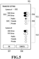
- Fig. 5 is a diagram showing an example of the transfer setting screen 501 presented to the user.
- the transfer setting screen 501 is a screen for the user to select an external service of a transfer destination and the like in a case where the transfer unit 404 automatically transfers a captured image received by the image management apparatus 103.
- the transfer setting screen 501 is described as being displayed on the terminal 106 of the user who has an account for a cloud storage service via a WEB application, the transfer setting screen 501 may be displayed on the displays 205 of the image capturing apparatuses 102a and 102b.
- the transfer setting screen 501 of the present embodiment includes setting regions 511 and 512 as regions through which to select the settings for each image capturing apparatus of the user registered in the image management apparatus 103. It is assumed that the image capturing apparatuses of the user registered in the image management apparatus 103 are "Camera A" corresponding to the image capturing apparatus 102a and "Camera B" corresponding to the image capturing apparatus 102b. In this case, the transfer setting screen 501 includes the setting region 511 through which to select the settings for "Camera A" and the setting region 512 through which to select the settings for "Camera B".
- the setting region 511 is a region through which to select the settings for "Camera A”
- a camera name display region 502 is a region that displays the name of the image capturing apparatus for which the settings are selected in the setting region 511.
- "Camera A” is displayed in the camera name display region 502 of the setting region 511.
- the setting region 511 is a region through which to select the settings for a captured image received from the image capturing apparatus 102a, which is "Camera A”.
- An external service name display region 503 displays the name of the external service which the user registered in the image management apparatus 103.
- the name of the external service provided by the information management apparatus 104a is "XXX Drive”
- the name of the external service provided by the information management apparatus 104b is “YYY Drive”.
- the description is made on the assumption that "XXX Drive” and "YYY Drive” are registered as external services in the image management apparatus 103.
- Switches 504 are provided to correspond respectively to the external services displayed in the external service name display region 503. In a case where the white circle of the switch 504 is moved to the right side for selection, it represents that the automatic transfer to the corresponding external service is selected to be valid. On the other hand, in a case where the white circle is moved to the left side for selection, it represents that the automatic transfer is selected to be invalid.
- the setting region 511 shown in Fig. 5 represents the state in which the automatic transfers to both external services of "XXX Drive” and "YYY Drive” are selected to be valid.
- the image management apparatus 103 receives a captured image from the image capturing apparatus 102a, which is "Camera A”
- the captured image is automatically transferred by the transfer unit 404 to the information management apparatus 104a, which provides "XXX Drive”.
- the captured image is also automatically transferred to the information management apparatus 104b, which provides "YYY Drive”.
- the setting region 512 is a region through which to make settings for the image capturing apparatus 102b.
- the setting region 512 shown in Fig. 5 represents the state in which the automatic transfer only to the external service of "XXX Drive" is selected to be valid.
- the transfer unit 404 the transfer unit 404 to the information management apparatus 104b, which provides "YYY Drive”.
- a disclosure range display region 505 is a region through which to select the setting value of an attribute of the disclosure range of an image transferred to an external service.
- Some external services are configured such that a captured image transferred from the image management apparatus 103 can be disclosed.
- Such an external service is referred to as an image-disclosable external service or an external service having a function to disclose a captured image.
- an image-disclosable external service is registered in the image management apparatus 103, the user can select the setting value indicating (the attribute of) the disclosure range of the image-disclosable external service.
- the description is made on the assumption that "YYY Drive" is an image-disclosable external service.
- the setting values indicating the disclosure range include, for example, "public”, “friends”, and “private”.
- "public” is a setting value that permits all the users who transmitted a request for obtaining an image to obtain the image.
- “friends” is a setting value that permits some users who are permitted by the user who possesses an image to obtain the image.
- User IDs of some users who are permitted by the user who possesses an image are stored in the form of a list in the storage apparatus 307 of the image management apparatus 103.
- the user who possesses an image designates objects such as the user names, the mail addresses, the face photos, and the like of the other users, which uniquely identify target users.
- the image management apparatus 103 finds a user ID corresponding to the objects, and adds the user ID to the list, so that a user ID list of the users permitted by the user who possesses the image is created.
- "private" is a setting value that does not permit users other than the user who possesses an image to obtain the image.
- Radio buttons 506 are buttons for selecting the setting value indicating the disclosure range of an image to be transferred to an external service.
- a black circle is displayed in the white circle for the setting value indicating the selected disclosure range.
- An OK button 507 is a button for transmitting the settings selected in the currently displayed transfer setting screen 501 to the image management apparatus 103.
- a cancel button 508 is a button for instructing cancellation of the selection status made by the user.
- the image management apparatus 103 of the present embodiment it is possible to associate an external service of the transfer destination in a case of automatically transferring an image from the image management apparatus 103 with each image capturing apparatus of the user registered in the image management apparatus 103.
- the image management apparatus 103 of the present embodiment can determine whether an external service is associated with the image capturing apparatus which transmitted the captured image. Then, in a case where an external service is associated, the received captured image can be automatically transferred only to the external service associated with the image capturing apparatus.
- the user who possesses two image capturing apparatuses wants to transfer a captured image captured with one of the image capturing apparatuses to all the registered external services, but wants to transfer a captured image captured with the other image capturing apparatus only to some of the external services.
- the user can select the transfer destination for each image capturing apparatus through the transfer setting screen 501.
- Figs. 6A to 6C are diagrams for explaining the transfer setting information, the image capturing apparatus information, and the external service information, which are managed by the information management unit 403 of the image management apparatus 103.
- the method for holding data in the transfer setting information, the image capturing apparatus information, and the external service information in Figs. 6A to 6C is an example, and data may be held in the form of a table.
- the transfer setting information holds the content of the settings selected by the user through the transfer setting screen 501.
- the transfer setting information in Fig. 6A is an example of information that holds the settings regarding the transfer, which are generated in a case where the OK button 507 is pressed in the state of the transfer setting screen 501 in Fig. 5 .
- the transfer setting information in Fig. 6A includes a userId attribute 601 and a devices attribute 602 associated with the userId attribute.
- the devices attribute 602 includes a deviceId attribute 603, a services attribute 604, a serviceId attribute 605, and a disclosureRange attribute 606.
- the userId attribute 601 is a region that holds an ID (referred to as a user ID) for uniquely identifying a user.
- the devices attribute 602 is a region that holds a list of image capturing apparatuses registered in association with the user ID.
- the deviceId attribute 603 is included in the devices attribute 602, and is a region that holds an ID (referred to as a camera ID) for uniquely identifying an image capturing apparatus registered in association with the user ID.
- the services attribute 604 is associated with each camera ID, and is a region that holds a list of external services associated with the image capturing apparatus identified by the camera ID.
- the serviceId attribute 605 is included in the services attribute 604, and is a region that holds an ID (referred to as an external service ID) for uniquely identifying an external service association with the camera ID.
- the user selects the switch 504 that validates the automatic transfer to a certain external service in the setting region for a certain image capturing apparatus, and presses the OK button 507, via the transfer setting screen 501.
- the external service ID identifying the external service selected as validated for the automatic transfer and the camera ID of the image capturing apparatus are associated and held in the transfer setting information.
- the camera ID identifying the image capturing apparatus of the user is associated with the user ID identifying the user.
- each camera ID is associated with the external service ID identifying the external service of the transfer destination of the captured image.
- the image management apparatus 103 of the present embodiment can determine to which external service the received captured image is transferred by referring to the transfer setting information.
- the disclosureRange attribute 606 is a region that holds the setting value indicating the disclosure range of an image-disclosable external service among external services associated with an image capturing apparatus associated with a user.
- the setting values indicating the disclosure range include "public”, “friends”, “private”, and the like as described above.
- Fig. 6B is a diagram showing an example of the image capturing apparatus information.
- the image capturing apparatus information holds information on image capturing apparatuses associated respectively with the camera IDs.
- a deviceName attribute 611 is a region that holds the name of an image capturing apparatus associated with the camera ID.
- a seriesName attribute 612 is a region that holds the name of a product series of the image capturing apparatus associated with the camera ID.
- the image capturing apparatus information in Fig. 6B holds information on image capturing apparatuses associated respectively with the camera IDs "dev01" and "dev02".
- Fig. 6C is a diagram showing an example of the external service information.
- the external service information holds information on external services associated with the respective external service IDs.
- a serviceName attribute 621 is a region that holds the name of an external service associated with the external service ID.
- a uri attribute 622 is a region that holds URI (Uniform Resource Identifier) of the external service associated with the external service ID.
- the disclosureRange attribute 623 is a region that holds the setting value indicating a settable disclosure range in a case where the external service associated with the external service ID is an image-disclosable external service.
- the external service information in Fig. 6C holds information on external services associated with the respective external service IDs "srv01" and "srv02".
- the transfer setting information in Fig. 6A is transfer setting information in which the user ID is "usr01", showing that the user to which "usr01” is assigned has registered two image capturing apparatuses of camera IDs of "dev01" and "dev02".
- the image capturing apparatus information in Fig. 6B it can be found that "dev01” represents the image capturing apparatus 102a having the name of "CameraA” and "dev02" represents the image capturing apparatus 102b having the name of "CameraB”.
- the image capturing apparatus 102a of the camera ID of "dev01” is associated with external services to which the external service IDs of "srv01" and “srv02" are assigned.
- the external service information in Fig. 6C in a case where the image management apparatus 103 receives a captured image captured by the image capturing apparatus 102a of "dev01", the automatic transfer of the captured image to the two external services "XXXDrive” and "YYYDrive” is registered to be valid.
- the setting value indicating the disclosure range is "Public” for the external service "YYYDrive” of the external service ID of "srv02".
- the image management apparatus 103 receives a captured image captured by the image capturing apparatus 102b of "dev02"
- the automatic transfer of the captured image only to the external service "XXXDrive” of the external service ID of "srv01" is registered to be valid.
- the captured image is not automatically transferred to the external service "YYYDrive” of the external service ID of "srv02". That is, it is set that a captured image captured by the image capturing apparatus 102b is not disclosed.
- Fig. 7 is a flowchart for explaining a flow of processes of transfer setting in the image management apparatus 103.
- the series of processes shown in the flowchart of Fig. 7 are performed by the CPU of the image management apparatus 103 deploying program codes stored in the ROM into the RAM, and executing the program codes. A result of executing each process is stored in the RAM 304.
- some or all of the functions in the steps in Fig. 7 may be achieved by hardware such as an ASIC or an electronic circuit. Note that the sign "S" in the description of each process means a step in the flowchart, and the same applies also in the following flowcharts.
- the reception unit 401 receives a display request for the transfer setting screen 501.
- the present flowchart is described, for example, on the assumption that the user transmits a request for transfer setting to the image management apparatus 103 via a WEB application installed in the terminal 106. In this case, the reception unit 401 receives a display request transmitted from the terminal 106. An instruction for transfer setting may be transmitted from the image capturing apparatus 102.
- the processing unit 402 reads the current transfer setting information managed by the information management unit 403, and generates information for displaying the transfer setting screen 501.
- the output unit 405 output the information for displaying the transfer setting screen 501 to the terminal 106, which is the apparatus which transmitted the display request for the transfer setting screen 501.
- the terminal 106 which received the information for displaying the transfer setting screen 501, the transfer setting screen 501 is displayed.
- transfer setting information representing the settings selected through the transfer setting screen 501 is transmitted from the terminal 106.
- the reception unit 401 receives the transfer setting information transmitted from the terminal 106.
- the information management unit 403 stores and manages the received transfer setting information in the ROM 303 or the storage apparatus 307. In a case where the transfer setting information of the user has already been managed, the transfer setting information is updated to the transfer setting information received at this time.
- Fig. 8 is a flowchart for explaining a flow of processes of automatic transfer in the image management apparatus 103.
- the series of processes shown in the flowchart of Fig. 8 are performed by the CPU of the image management apparatus 103 deploying program codes stored in the ROM into the RAM, and executing the program codes. A result of executing each process is stored in the RAM 304.
- some or all of the functions in the steps in Fig. 8 may be achieved by hardware such as an ASIC or an electronic circuit.
- the reception unit 401 receives a captured image transmitted from the image capturing apparatus 102a or 102b.
- the processing unit 402 obtains the camera ID of an image capturing apparatus which transmitted the captured image, that is, the image capturing apparatus used for capturing the received captured image, from EXIF added to the captured image received in S801.
- the camera ID obtained in this step is referred to as a camera ID0.
- S803 to S813 are loop processing.
- the transfer unit 404 obtains the current transfer setting information of the target user via the information management unit 403, and selects a camera ID to be processed from camera IDs registered in association with the user ID of the user in the transfer setting information.
- the i-th camera ID to be processed is referred to as a camera IDi.
- the processes of S804 to S812 are repeated on the camera IDi.
- the transfer unit 404 determines whether or not the camera IDi and the camera ID0 coincide. That is, it is determined whether the camera ID0 of the image capturing apparatus which captured the captured image received in S801 and the camera IDi currently to be processed coincide. If it is determined that the camera IDi to be processed coincides with the camera ID0 (YES in S804), the processing proceeds to S805. On the other hand, if it is determined that the camera IDi to be processed does not coincide with the camera ID0 (NO in S804), the processing on the camera IDi currently to be processed is ended, and the processing proceeds to S813 in which it is determined whether all the camera IDs were selected to be processed.
- the transfer unit 404 determines whether there is an external service associated with the camera IDi currently to be processed, based on the transfer setting information. That is, it is determined whether there is an external service ID associated with the camera ID0 of the image capturing apparatus which captured the captured image received in S801. If there is an external service ID associated with the camera ID0 (YES in S805), the processing proceeds to S806. If there is not an external service ID associated with the camera ID0 (NO in S805), the processing proceeds to S813. Otherwise, the present flowchart may be ended.
- S806 to S812 are loop processing.
- the transfer unit 404 selects an external service ID to be processed from the external service IDs associated with the camera ID currently to be processed, that is, the camera ID0 of the image capturing apparatus which captured the received captured image.
- the j-th external service ID selected to be processed is referred to as an external service IDj.
- the processes of S807 to S811 are repeated on the external service IDj to be processed.
- the transfer unit 404 obtains a value of the external service IDj of the external service currently to be processed from the transfer setting information.
- the transfer unit 404 sets the setting value indicating the disclosure range obtained in S809 in a transfer parameter.
- This transfer parameter is a parameter additionally transmitted in a case where a captured image received in S801 is transferred to the information management apparatus 104 which provides an external service.
- This transfer parameter may include the setting value indicating the disclosure range, the title of the image, the explanation, and the like.
- the transfer unit 404 obtains URL of transfer destination from the uri attribute 622 associated with the external service IDj currently to be processed in the external service information in Fig. 6C .
- the transfer unit 404 obtains URL of the transfer destination by searching the external service information by using the external service IDj as a key. Then, the transfer unit 404 transmits the captured image received in S801 and the transfer parameter to the obtained URL, thus performing the automatic transfer to the external service corresponding to the external service IDj currently to be processed.
- the present embodiment it is possible to select an external service to which the automatic transfer is performed for each image capturing apparatus. Moreover, in a case where performing the automatic transfer is selected, it is possible to set the disclosure range of the image in the external service of the transfer destination in association with the image capturing apparatus. Hence, according to the present embodiment, it is possible to prevent a captured image that is not intended to be disclosed by a user from being disclosed in an external service.
- the functions of the image management apparatus 103 may include an initialization unit configured to initialize information held in the transfer setting information.
- the initialization unit initializes the transfer setting information to invalidate the transfer to an external service. Hence, it is possible to prevent a captured image that is not intended to be disclosed from being transferred to an external service.
- the initialization unit initializes the transfer setting information to set the setting value indicating the disclosure range to a non-disclosing setting value such as "private". Hence, even if a captured image is transferred to an external service, it is possible to prevent the captured image that is not intended to be disclosed by the user from being disclosed.
- the initialization unit for example after an external service is registered, initializes information on the registered external service in the transfer setting information. Alternatively, the initialization unit initializes in a case where an image capturing apparatus is newly registered in the transfer setting information when an image capturing apparatus has already been registered in the transfer setting information. In some cases where the transfer to an external service is validated for the first time, it is acknowledged that the user intends to disclose a captured image. However, there may be a possibility that thereafter, in a case where an image capturing apparatus for capturing a captured image that is not intended to be disclosed is registered, the user has forgotten the settings of transfer to the previously registered external service. Hence, in a case where a new image capturing apparatus is registered, it is possible to prevent a captured image that is not intended to be disclosed from being disclosed, by such initialization that does not allow a captured image captured by the image capturing apparatus to be disclosed.
- Embodiment 1 a method for transferring a received captured image based on a transfer setting screen and transfer setting information having configurations different from Embodiment 1 is described.
- differences from Embodiment 1 are mainly described. Portions that are not particularly specified have the same configurations and processes as those in Embodiment 1, and the configurations of the same functions as those in Embodiment 1 are denoted by the same reference signs, and the descriptions are omitted.
- Fig. 9A is a diagram showing an example of a transfer setting screen 911 of the present embodiment.
- the transfer setting screen 911 of the present embodiment is configured to correspond to transfer setting information of the present embodiment, which is described later.
- the transfer setting screen 911 of the present embodiment includes setting regions 921 and 922 in the same manner as in the transfer setting screen 501 of Embodiment 1 of Fig. 5 .
- the setting regions 921 and 922 are provided respectively for registered external services. If it is assumed that the registered external services are "XXX Drive” and "YYY Drive", the transfer setting screen 911 includes the setting region 921 regarding "XXX Drive” and the setting region 922 regarding "YYY Drive".
- An external service name display region 912 of the setting region 921 is a region that displays the name of the external service to be set in the setting region 921. Since "XXX Drive" is displayed in the external service name display region 912 of the setting region 921, the setting region 921 is a region through which to set by which image capturing apparatus, a captured image to be transferred to "XXX Drive” was captured.
- a camera name display region 913 included in the setting region 921 the names of image capturing apparatuses registered by the user in the image management apparatus 103 are displayed.
- Switches 914 are provided to correspond respectively to the image capturing apparatuses displayed in the camera name display region 913.
- the white circle of the switch 914 is set to the right side, it represents that for an image captured by the corresponding image capturing apparatus and transmitted to the image management apparatus 103, the automatic transfer to the external service displayed in the external service name display region 912 of the setting region 921 is selected to be valid.
- the white circle is set to the left side, it represents that the automatic transfer is selected to be invalid.
- the setting region 922 is a region through which to make settings regarding the automatic transfer to "YYY Drive” which is an image-disclosable external service.
- disclosure-type display regions 915 and radio buttons 916 are provided to correspond respectively to the image capturing apparatuses registered in the image management apparatus 103 in addition to the items included in the setting region 921.
- the user can select an image capturing apparatus which captured a captured image to be automatically transferred, for each external service.
- an image capturing apparatus which captured a captured image to be automatically transferred, for each external service.
- the user registers a large number of image capturing apparatuses in the image management apparatus 103.
- selecting an image capturing apparatus to be subjected to the automatic transfer for each external service makes the operation of the user easier.
- Fig. 9B is a diagram for explaining transfer setting information of the present embodiment.
- the transfer setting information of the present embodiment includes a userId attribute 901 and a services attribute 902.
- the services attribute 902 includes a serviceId attribute 903, a devices attribute 904, a deviceId attribute 905, and a disclosureRange attribute 906.
- the services attribute 902 is a region that holds a list of external services registered in association with the user ID.
- the serviceId attribute 903 is a region that holds an external service ID of an external service included in the list of external services.
- the devices attribute 904 is a region that holds a list of image capturing apparatuses associated with each of the external service IDs for specifying a captured image to be transferred to the external service indicated by the external service ID. That is, the list of image capturing apparatuses for determining whether the captured image is a captured image to be transferred to the external service indicated by the external service ID.
- the deviceId attribute 905 is a region that holds a camera ID of an image capturing apparatus included in the list of image capturing apparatuses for specifying a captured image to be transferred.
- the disclosureRange attribute 906 is a region that holds a setting value indicating a disclosure range.
- each external service ID included in the serviceId attribute 903 is associated with the camera ID of the image capturing apparatus associated with the external service ID.
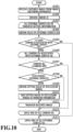
- Fig. 10 is a flowchart for explaining a flow of processes of automatic transfer in the present embodiment. Since S1001 to S1002 are the same processes as S801 to S802, the descriptions are omitted.
- S 1003 to S 1013 are loop processing.
- the transfer unit 404 obtains the current transfer setting information of the target user via the information management unit 403. Then, the transfer unit 404 selects an external service ID to be processed from external service IDs associated with the user ID of the user in the transfer setting information.
- the i-th external service ID to be processed is referred to as an external service IDi in the present embodiment. Then, the processes of S1004 to S1012 are repeated on the external service IDi.
- the transfer unit 404 obtains a value of the external service IDi corresponding to the external service currently to be processed from the transfer setting information.
- the transfer unit 404 determines whether there is a camera ID associated with the external service IDi currently to be processed, based on the transfer setting information. If it is determined that there is a camera ID associated with the external service IDi (YES in S1005), the processing proceeds to S1006. If it is determined that there is not a camera ID associated with the external service IDi (NO in S1005), the processing proceeds to S1013, and it is determined whether all the external service IDs were selected to be processed.
- S1006 to S1012 are loop processing.
- the transfer unit 404 selects a camera ID to be processed from camera IDs associated with the external service IDi currently to be processed.
- the j-th camera ID to be processed is referred to as a camera IDj.
- the processes of S1007 to S1011 are repeated on the camera IDj to be processed.
- the transfer unit 404 determines whether or not the camera IDj currently to be processed and the camera ID0 coincide. If it is determined that the camera IDj to be processed coincides with the camera ID0 (YES in S1007), the processing proceeds to S1008. If it is determined that the camera IDj does not coincide with the camera ID0 (NO in S1007), the loop processing on the camera IDj currently to be processed is ended, and the processing proceeds to S1012 in which it is determined whether all the camera IDs were selected to be processed.
- the transfer unit 404 determines whether or not the setting value indicating the disclosure range is associated with the external service IDi currently to be processed. The method for determination may be the same as in S808. If it is determined that the setting value indicating the disclosure range is associated (YES in S1008), the processing proceeds to S1009.
- the transfer unit 404 obtains the setting value indicating the disclosure range associated with the camera ID0 associated with the external service IDi currently to be processed, from the transfer setting information.
- the transfer unit 404 sets the setting value indicating the disclosure range obtained in S1009 in the transfer parameter.
- the transfer unit 404 obtains URL of transfer destination from the uri attribute 622 associated with the external service IDi to be processed in the external service information. Then, the transfer unit 404 transmits the captured image received in S1001 and the transfer parameter to the obtained URL, thus performing the automatic transfer to the external service associated with the external service IDi to be processed.
- Fig. 11A and 11B are diagrams showing an example of the transfer setting screen of the present embodiment.
- the transfer setting screen generated by the processing unit 402 of the present embodiment includes a common setting screen 1101 of Fig. 11A and an individual setting screen 1111 of Fig. 11B .
- the individual setting screen 1111 has the same configuration and function as those of the transfer setting screen 911 of Embodiment 2. Specifically, in the individual setting screen 1111, the user can select whether the automatic transfer is validated or invalidated and select a setting value indicating the disclosure range for each image capturing apparatus, on each of external services registered in the image management apparatus 103. In addition, based on the settings selected in the individual setting screen 1111, the transfer unit 404 determines whether the automatic transfer is performed.
- the common setting screen 1101 is a screen displayed before the individual setting screen 1111 is displayed on a terminal 106 which received information for displaying a transfer setting screen transmitted in S703 in Fig. 7 .
- the common setting screen 1101 is a screen for selecting settings selected in advance in the individual setting screen 1111 when the individual setting screen 1111 is displayed.
- the common setting screen 1101 does not include a region for selecting settings for each image capturing apparatus. It is possible to select whether the automatic transfer is validated or invalidated and select a setting value indicating the disclosure range for each of registered external services.
- Switches 1103 are provided to correspond respectively to the external services displayed in the external service name display region 1102. In a case where the white circle of the switch 1103 is moved to the right side for selection, it represents that the automatic transfer to the corresponding external service is selected to be valid. On the other hand, in a case where the white circle is moved to the left side for selection, it represents that the automatic transfer is selected to be invalid.
- a disclosure-type display region 1104 and a radio button 1105 are provided below the name of an image-disclosable external service, and are provided for selecting the setting value indicating the disclosure range of an image to be transferred to the external service.
- the processing unit 402 generates information for displaying the individual setting screen 1111 such that the individual setting screen 1111 to which the screen was transitioned by pressing the OK button 1106 is displayed while reflecting the settings selected in the common setting screen 1101.
- the information for displaying the individual setting screen 1111 is outputted to the terminal 106 or the like by the output unit 405.
- the settings selected in the common setting screen 1101 can be changed in the individual setting screen 1111. Pressing the OK button 1117 in the individual setting screen 1111 transmits the settings selected in the currently displayed individual setting screen 1111 to the image management apparatus 103.
- switches 1114 corresponding to all the image capturing apparatuses included in a setting region 1115 for setting the external service "XXX Drive” are displayed in the state of being selected to validate the automatic transfer.
- Fig. 11C is a diagram for explaining transfer setting information of the present embodiment.
- the transfer setting information holds the content of the settings in a case where the user presses the OK buttons 1106 and 1117 in the common setting screen 1101 and the individual setting screen 1111.
- the transfer setting information in Fig. 11C is an example of transfer setting information that is generated in a case where the OK button 1106 or 1117 is pressed in the state of Fig. 11A or 11B .
- the transfer setting information of the present embodiment includes a userId attribute 1121, a common attribute 1131, and an individual attribute 1141.
- the common attribute 1131 is a region that holds the settings selected by the user in the common setting screen 1101.
- a services attribute 1132 included in the common attribute 1131 is a region that holds a list of external services for which the automatic transfer is selected in the common setting screen 1101.
- a serviceId attribute 1133 is a region that holds an external service ID of an external service included in the list of external services.
- a disclosureRange attribute 1135 is a region that holds a setting value indicating the attribute of a disclosure range.
- the individual attribute 1141 is a region that holds the settings selected in the individual setting screen 1111.
- the individual attribute 1141 includes a services attribute 1142. Since the configuration of the services attribute 1142 of the individual attribute 1141 is the same as the services attribute 902 of the transfer setting information in Fig. 9B , the description is omitted.
- the transfer processing in the present embodiment is the same as the flowchart of Fig. 10 .
- the transfer processing is performed with portions described as the transfer setting information in the flowchart of Fig. 10 being read as information of the individual attribute 1141 in the transfer setting information. That is, the transfer processing is performed by referring to a value included in the individual attribute in Fig. 11C .
- the user can collectively select whether the automatic transfer is validated or invalidated for each external service all at once in the registered image capturing apparatus. Hence, the burden for a user to select the settings for each image capturing apparatus can be reduced.
- processing for recommending a user to invalidate the automatic transfer to an image-disclosable external service in a case where predetermined conditions are satisfied is described.
- differences from Embodiment 1 are mainly described. Portions that are not particularly specified have the same configurations and processes as those in Embodiment 1, and the configurations of the same functions as those in Embodiment 1 are denoted by the same reference signs, and the descriptions are omitted.
- Fig. 12A is a diagram for explaining the processing for recommending a user to invalidate the automatic transfer to an image-disclosable external service.
- the sign "S" in Fig. 12A means a step of the processing, and the process of each step is performed by the CPU of the image management apparatus 103 deploying program codes stored in the ROM into the RAM, and executing the program codes.
- the reception unit 401 receives a captured image transmitted from an image capturing apparatus in the same manner as in S801 in Fig. 8 or S1001 in Fig. 10 . Note that the present embodiment is described on the assumption that a captured image is received from the image capturing apparatus 102b having the name of "Camera B".
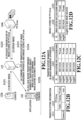
- Fig. 12B is a diagram in which part of information included in the transfer setting information is represented with a table.
- a column 1211 is a column that holds a name of an image capturing apparatus registered in the image management apparatus 103.
- a column 1212 is a column that holds a setting value indicating a disclosure range selected in association with the external service "YYY Drive” and the image capturing apparatus held in the column 1211.
- Each row after the first row of the table of Fig. 12B holds information of the setting value indicating the disclosure range associated with the image capturing apparatus held in the column 1211. It is represented that for the image capturing apparatus of each row, the setting value indicating the disclosure range indicated by an index in the first row in the column that holds "true” is selected.
- the example of the table of Fig. 12B represents that a captured image transmitted from the image capturing apparatus 102b having the name of "Camera B" is transferred to the external service "YYY Drive” with the setting value "private” indicating the disclosure range being set in the transfer parameter.
- the processing unit 402 requests transmission of an image stored in the account of the user of the external service or a list of images stored therein from the information management apparatus which provides an image-disclosable external service.
- the image-disclosable external service is "YYY Drive”
- the information management apparatus which provides the external service is the information management apparatus 104b.
- the processing unit 402 receives a stored image or list from the information management apparatus 104b which provides the image-disclosable external service.
- the following description is made on the assumption that a list of images stored in the account of the user of the external service "YYY Drive" is requested and received.
- a table of Fig. 12D is a diagram showing an example of a list of captured images stored in the account of the user of the external service "YYY Drive”.
- a column 1231 is a column that holds IDs for uniquely identifying stored captured images.
- a column 1232 is a column that holds image-capture dates of the stored captured images.
- a column 1233 is a column that holds setting values indicating disclosure ranges of the captured images stored in the external service "YYY Drive”. It is assumed that the captured images contained in the table of Fig. 12D are captured images captured by the image capturing apparatus 102b.
- the processing unit 402 obtains a list of history of captured images automatically transferred to the image-disclosable external service.
- a table of Fig. 12C is a diagram showing an example of a list of history of automatically transferring captured images received by the image management apparatus 103 to "YYYDrive".
- a column 1221 is a column that holds IDs for uniquely identifying transferred captured images.
- a column 1222 is a column that holds image-capture dates of the transferred captured images.
- a column 1223 shows setting values indicating disclosure ranges set in the transfer parameter in cases where the captured images were transferred to "YYY Drive". It is assumed that the captured images contained in the table of Fig. 12C are captured images captured by the image capturing apparatus 102b.
- the processing unit 402 compares the captured images held in the list of transfer history of Fig. 12C and the captured images held in the list of captured images stored in the account of the user of "YYY Drive" of Fig. 12D . Note that it is assumed that captured images after a predetermined image-capture date are compared. In addition, it is assumed that captured images captured by the same image capturing apparatus are compared.
- the ratio of the number of captured images deleted in "YYYDrive” to the number of captured images transferred to "YYY Drive” is calculated, and it is determined whether the ratio is equal to or more than a threshold. In a case where all the transferred captured images were deleted in "YYY Drive", the ratio is calculated to be 100%. In a case where the processing unit 402 determines that the calculated ratio is equal to or more than the threshold, the processing proceeds to S1205. On the other hand, in a case where the processing unit 402 determines that the calculated ratio is less than the threshold, the processing ends without executing S1205, which is described later.
- the list of transfer history of Fig. 12C and the list of captured images stored in the account of the user of "YYY Drive” of Fig. 12D are compared. Then, it is found that among five captured images transferred to "YYY Drive", there are two captured images stored in "YYY Drive". Hence, since three captured images were deleted among the transferred captured images, the ratio of the number of captured images deleted in the external service is equal to or more than 50%. Hence, in a case where the threshold is set to 50%, as a result of determination of S1204, the processing proceeds to S1205.
- the processing unit 402 performs processing for recommending the user to invalidate the setting of automatically transferring captured images captured by the image capturing apparatus, which were compared in S1204, to the image-disclosable external service.
- a method for recommending the user to invalidate the automatic transfer for example, a confirmation screen on whether the setting of automatically transferring captured images captured by the image capturing apparatus 102b to "YYY Drive” is changed is displayed on the terminal 106 of the user.
- a transfer setting screen in the state where the setting of automatically transferring captured images captured by the image capturing apparatus 102b to "YYY Drive" is selected to be invalid is displayed on the terminal 106 of the user.
- the image capturing apparatus is an image capturing apparatus for capturing a captured image that is not intended to be disclosed.
- the threshold is described as a predetermined ratio, the threshold may be a predetermined number of images.
- the processes of S1202 to S1205 may be executed before the automatic transfer to the external service is executed in S811 in Fig. 8 or S1011 in Fig. 10 .
- the automatic transfer of a captured image received in S1201 is stopped until S1202 to S1205 are executed. Then, the processing is not transitioned to S1205 as a result of determination of S1204, and the transfer to the external service is executed. Otherwise, after the processing is transitioned to S1205 as a result of determination of S1204 and the recommendation to the use is performed in S1205, in a case where the setting of automatic transfer remains as it is, the transfer to the external service is executed.
- processing for issuing a notification to a user to recommend changing a setting value indicating a disclosure range regarding transfer of an image to an image-disclosable external service in a case where predetermined conditions are satisfied is described.
- differences from Embodiment 1 are mainly described. Portions that are not particularly specified have the same configurations and processes as those in Embodiment 1, and the configurations of the same functions as those in Embodiment 1 are denoted by the same reference signs, and the descriptions are omitted.
- Fig. 13A is a diagram for explaining processing for recommending changing a setting regarding transfer of an image to an image-disclosable external service.
- the process of each step in Fig. 13A is performed by the CPU of the image management apparatus 103 deploying program codes stored in the ROM into the RAM, and executing the program codes.
- S1301 is the same process as S1201 in Fig. 12A . Then, the processing for automatically transferring a captured image received in S1301 to an external service is performed based on transfer setting information. Note that processes of S1302 to S1305 may be performed before the processing of automatically transferring a captured image to an external service is executed, as in the case of Embodiment 4.
- Fig. 13B is a diagram in which part of information included in the transfer setting information is represented with a table, and the configuration of the table is the same as the table in Fig. 12B .
- a captured image transmitted from the image capturing apparatus 102b having the name of "Camera B" is transferred to the external service "YYY Drive” with the setting value "Friends" indicating the disclosure range being set in the transfer parameter.
- the processing unit 402 requests a list of setting values indicating disclosure ranges of captured images stored in the account of the user of the image-disclosable external service from the information management apparatus which provides the image-disclosable external service.
- the image-disclosable external service is "YYY Drive”
- the information management apparatus which provides the external service is the information management apparatus 104b.
- the processing unit 402 receives the list of the setting values indicating the disclosure ranges of the stored captured images from the information management apparatus 104b which provides the image-disclosable external service.
- a table of Fig. 13C is a diagram showing an example of a list of setting values indicating disclosure ranges of captured images stored in the account of the user of "YYY Drive".
- a column 1331 is a column that holds IDs for uniquely identifying stored captured images.
- a column 1332 is a column that holds image-capture dates of the stored captured images.
- a column 1333 is a column that holds setting values indicating disclosure ranges of the captured images stored in "YYY Drive”.
- the processing unit 402 obtains, from transfer setting information, a setting value indicating a disclosure range to be added to a transfer parameter in a case where the image management apparatus 103 automatically transfers an image to an image-disclosable external service. Then, the processing unit 402 compares the obtained setting value indicating the disclosure range (the setting value indicating the disclosure range of Fig. 13B ) and setting values indicating disclosure ranges after a predetermined image-capture date in the list of Fig. 13C . Note that it is assumed that a setting value indicating a disclosure range associated with a certain image capturing apparatus, which is obtained from transfer setting information, and a setting value indicating a disclosure range of a captured image captured by the image capturing apparatus in an external service are compared.
- the ratio of setting values different from the setting value held in the current transfer setting information of Fig. 13B is calculated, and it is determined whether the ratio is equal to or more than a threshold.
- the processing unit 402 determines that the calculated ratio is less than the threshold, the processing ends without executing S1305, which is described later.
- the processing unit 402 determines that the calculated ratio is equal to or more than the threshold, the processing proceeds to S1305.
- the setting value indicating the disclosure range to be selected and added to the transfer parameter at the time of transfer is selected to be "Friends".
- the setting values indicating the disclosure ranges selected with "YYY Drive” held in the column 1333 of the table of Fig. 13C it is found that there are three captured images having the setting values different from the setting value "Friends" at the time of transfer, among five transferred captured images.
- the setting values indicating the disclosure ranges were changed in "YYY Drive" of the transfer destination.
- the processing proceeds to S1305.
- the processing unit 402 performs the processing of recommending the user to change the setting regarding automatic transfer of a captured image captured by the image capturing apparatus to be compared in S1204 to an image-disclosable external service. For example, recommendation is made to change the setting value indicating the disclosure range of the image capturing apparatus 102b held in the transfer setting information to the most frequently selected setting value among setting values indicating disclosure ranges selected for captured images captured by the image capturing apparatus 102b in "YYY Drive". In the list of Fig. 13C , the most frequently selected setting value is "Private". Hence, the processing unit 402 performs the processing of recommending the user to change the setting value of "Camera B" (the image capturing apparatus 102b) held in the transfer setting information of Fig. 13B from "Friend" to "Private".
- a confirmation screen on whether the setting of automatically transferring captured images captured by the image capturing apparatus 102b to "YYY Drive” is changed is displayed on the terminal 106 of the user.
- a transfer setting screen in the state in which the setting value indicating the disclosure range in a case where a captured image captured by the image capturing apparatus 102b is automatically transferred to "YYY Drive” was changed to "Private” is displayed on the terminal 106 of the user.
- the threshold is described as a predetermined ratio, the threshold may be a predetermined number of images.
- the determination of S 1204 may be made to be weighted with a temporal distance of an image-capture date based on the current date. In this case, the determination may be made by comparing such a weighted sum that 1 point is given in a case where the setting value of the transfer setting information and the setting value in the external service coincide and 0 point is given in a case where the setting values do not coincide with a threshold.
- inventions may take, for example, embodiments as systems, apparatuses, methods, programs, recording media (storage media), or the like. Specifically, the embodiments may be applied to a system including a plurality of devices (for example, a host computer, an interface device, an image capturing apparatus, a Web application, and the like), or may be applied to an apparatus including a single device.
- a host computer for example, a host computer, an interface device, an image capturing apparatus, a Web application, and the like
- an apparatus including a single device for example, a single device.
- a recording medium (or a storage medium) that has recorded program codes (computer programs) of software that achieves the functions of the above-described embodiments is supplied to a system or apparatus. It goes without saying that this storage medium is a readable storage medium. Then, a computer (or a CPU or MPU) of the system or apparatus reads program codes stored in the storage medium and executes the program codes. In this case, the program codes read from the recording medium themselves achieve the functions of the aforementioned embodiments, and thus the recording medium in which the program codes are recorded is included in the technique of the above-described embodiments.
- Embodiment(s) of the present disclosure can also be realized by a computer of a system or apparatus that reads out and executes computer executable instructions (e.g., one or more programs) recorded on a storage medium (which may also be referred to more fully as a 'non-transitory computer-readable storage medium') to perform the functions of one or more of the above-described embodiment(s) and/or that includes one or more circuits (e.g., application specific integrated circuit (ASIC)) for performing the functions of one or more of the above-described embodiment(s), and by a method performed by the computer of the system or apparatus by, for example, reading out and executing the computer executable instructions from the storage medium to perform the functions of one or more of the above-described embodiment(s) and/or controlling the one or more circuits to perform the functions of one or more of the above-described embodiment(s).
- ASIC application specific integrated circuit
- the computer may comprise one or more processors (e.g., central processing unit (CPU), micro processing unit (MPU)) and may include a network of separate computers or separate processors to read out and execute the computer executable instructions.
- the computer executable instructions may be provided to the computer, for example, from a network or the storage medium.
- the storage medium may include, for example, one or more of a hard disk, a random-access memory (RAM), a read only memory (ROM), a storage of distributed computing systems, an optical disk (such as a compact disc (CD), digital versatile disc (DVD), or Blu-ray Disc (BD) TM ), a flash memory device, a memory card, and the like.
Landscapes
- Engineering & Computer Science (AREA)
- Signal Processing (AREA)
- Multimedia (AREA)
- General Engineering & Computer Science (AREA)
- Theoretical Computer Science (AREA)
- Computing Systems (AREA)
- Physics & Mathematics (AREA)
- General Physics & Mathematics (AREA)
- Human Computer Interaction (AREA)
- Computer Networks & Wireless Communication (AREA)
- Studio Devices (AREA)
- Facsimiles In General (AREA)
- Management, Administration, Business Operations System, And Electronic Commerce (AREA)
Abstract
Description
- The present disclosure relates to processing related to image management.
- In recent years, storage services that store data uploaded by users are being widely used.
- On the Internet (https://image.canon/st/en/features.html?region=0, retrieved on June 15, 2022, Canon Inc. "Image.canon") (hereinafter, NPL 1), a photo storage service that receives a captured image transmitted from a user's camera having a transmission function, and stores the received captured image in a storage region assigned to each user is described. In addition, in the photo storage service of
NPL 1, if an external storage service which a user uses has been registered, a received captured image can be automatically transferred to the registered external storage service. Some external storage services provide a service to disclose captured images stored therein. By setting such automatic transfer of captured images to an external storage service in the photo storage service ofNPL 1, it is possible to disclose a captured image immediately after capturing the image. - Meanwhile, as described on the Internet (https://www.makuake.com/project/powershotpick/, retrieved on June 15, 2022, Canon Marketing Japan Inc., "Canon's automatic image-capturing camera PowerShot PICK") (hereinafter, NPL 2), cameras that automatically capture private images are being spread. In addition, it is possible that a user possesses a plurality of cameras each having a function to transmit captured images to the photo storage service of
NPL 1. In this case, it is possible that needs arise for an operation in which captured images captured by a camera for capturing images to be disclosed are disclosed, but captured images captured by a camera for capturing images to be private are not disclosed. - However, in the photo storage service of
NPL 1, once an external storage service of a transfer destination is registered, captured images transmitted to the account of the user are automatically transferred to the registered external storage service. For this reason, there is a possibility that a captured image captured by a camera for capturing images to be private is disclosed. - The present invention in its first aspect provides an image management apparatus as specified in
claims 1 to 18. - The present invention in its second aspect provides a control method as specified in claims 19
- The present invention in its third aspect provides program as specified in claim 20.
- Further features of the present disclosure will become apparent from the following description of exemplary embodiments with reference to the attached drawings.
-
-
Fig. 1 is a diagram showing an example of a configuration of an image management system; -
Fig. 2 is a diagram showing an example of a hardware configuration of an image capturing apparatus; -
Fig. 3 is a diagram showing an example of a hardware configuration of the image management apparatus; -
Fig. 4 is a diagram showing an example of a functional configuration of the image management apparatus; -
Fig. 5 is a diagram showing an example of a transfer setting screen; -
Figs. 6A to 6C are diagrams showing an example of transfer setting information; -
Fig. 7 is a flowchart for explaining an example of a flow of processes of transfer setting; -
Fig. 8 is a flowchart for explaining an example of a flow of processes of transfer; -
Figs. 9A and 9B are diagrams showing an example of transfer setting information and a transfer setting screen; -
Fig. 10 is a flowchart for explaining an example of a flow of processes of transfer; -
Figs. 11A to 11C are diagrams showing an example of transfer setting information and a transfer setting screen; -
Figs. 12A to 12D are diagrams for explaining an example of processing for recommending invalidating automatic transfer; and -
Figs. 13A to 13C are diagrams for explaining processing for recommending changing a disclosure range. - Hereinafter, an embodiment of the technique of the present disclosure is described with reference to the attached drawings. Note that a configuration shown in the following embodiment is only an example, and the present disclosure is not limited to the configuration shown in the drawings.
- In addition, in reference signs, terms different only in alphabets attached behind a number denote apparatuses having the same function, and in a case of indicating one of apparatuses having the same function, the alphabet of reference sign may be omitted in some cases.
-
Fig. 1 is a system configuration of animage management system 101 according to the present embodiment. Theimage management system 101 includesimage capturing apparatuses image management apparatus 103,information management apparatuses terminal 106. - The image capturing
apparatuses apparatuses image management apparatus 103 through anetwork 105. - The
image management apparatus 103 is an information processing apparatus that provides a cloud service. Specifically, theimage management apparatus 103 provides a cloud storage service that receives and stores image data transmitted from theimage capturing apparatuses image capturing apparatuses image management apparatus 103 by creating an account and registering the user's image capturing apparatuses. The detail of the functions of theimage management apparatus 103 are described later. - The
information management apparatuses image management apparatus 103. The service provided by each of theinformation management apparatuses image management system 101 includes theinformation management apparatuses - The
terminal 106 is, for example, a PC, a tablet, a smartphone, or the like. In theterminal 106, a Web application that operates in a browser is installed. The user who has an account for the cloud storage service provided by theimage management apparatus 103 can perform browsing, deletion, and the like of an image file stored in the cloud storage service via the Web application. Moreover, the user can change the setting regarding the cloud storage service via the Web application. - The
network 105 is, for example, LAN (Local Area Network), the Internet, or the like. The image capturingapparatuses image management apparatus 103, theinformation management apparatus terminal 106 are coupled via thenetwork 105, so that intercommunications among apparatuses can be achieved. -
Fig. 2 is a diagram of a hardware configuration of theimage capturing apparatus 102a. Since the hardware configuration of theimage capturing apparatus 102b is the same as the configuration described below, its description is omitted. In the case of designating one of theimage capturing apparatuses image capturing apparatus 102 by omitting the alphabet of the reference sign in some cases unless otherwise noted. Theimage capturing apparatus 102a includes aCPU 202, aROM 203, aRAM 204, adisplay 205, anoperation unit 206, astorage apparatus 207, a network I/F 208, animage capturing element 209, and abus 210. - The
CPU 202 is a Central Processing Unit. TheCPU 202 reads programs stored in thestorage apparatus 207, and interprets and executes the programs to control theRAM 204, thedisplay 205, and the like which are coupled via thebus 210. TheROM 203 is a Read Only Memory that performs input and output control with hardware coupled to thebus 210. TheRAM 204 is a Random Access Memory that temporarily stores information used in calculation by theCPU 202. - The
display 205 is a display unit that displays a result of processing executed by theCPU 202, and the like. Theoperation unit 206 is an operation unit that includes a button, a touch panel, and the like, and receives input from the user. - The
storage apparatus 207 stores programs and data used in processing by theCPU 202, as well as, captured images captured by theimage capturing element 209, and supplementary information such as shutter speed, aperture, photometry method, exposure, ISO sensitivity, and white balance. - The network I/
F 208 provides communication functions such as an interface (I/F) to couple to a network such as a local network, an intranet, or the Internet. Theimage capturing apparatus 102a is capable of communicating with other devices such as theimage management apparatus 103 via thenetwork 105 from the network I/F 208. - The
image capturing element 209 is, for example, a CCD (Charge Coupled Device), a CMOS (Complementary Metal Oxide Semiconductor), or the like, and converts received light into electric signals and records the electric signals as an image. - The
bus 210 is a signal line to which each unit of the hardware of the aforementionedimage capturing apparatus 102a is coupled. - The functions of the image capturing program are achieved by the
CPU 202 executing processing based on the programs stored in thestorage apparatus 207. The image capturing program includes, for example, a function to transfer a captured image captured by theimage capturing apparatus 102 to the cloud storage service provided by theimage management apparatus 103 via the network I/F 208. -
Fig. 3 is a diagram of a hardware configuration of theimage management apparatus 103 according to the present embodiment. Theimage management apparatus 103 includes aCPU 302, aROM 303, aRAM 304, adisplay 305, akeyboard 306, astorage apparatus 307, a network I/F 308, apointing device 309, and abus 310. Theimage management apparatus 103 may be achieved by a single information processing apparatus having each unit inFig. 3 , or may be achieved by a plurality of information processing apparatuses each having at least some of the units inFig. 3 . In a case where theimage management apparatus 103 is achieved by a plurality of information processing apparatuses, the plurality of information processing apparatuses are coupled by a LAN or the like to be capable of communicating with one another. - The
CPU 302 reads programs stored in thestorage apparatus 307, and interprets and executes the programs to control theRAM 304, thedisplay 305, and the like which are coupled to thebus 310. TheROM 303 is a read only memory that performs input and output control with hardware coupled to thebus 310. TheRAM 304 is a random access memory that temporarily stores information used in calculation by theCPU 302. - The
display 305 is a display unit that displays a result of processing executed by theCPU 302, and the like. Thekeyboard 306 is an operation unit that receives input from the user. In a case where thedisplay 305 of theimage management apparatus 103 includes a touch panel, thekeyboard 306 does not have to be included in theimage management apparatus 103. - The
storage apparatus 307 is a storage apparatus that stores programs and data used in the processing by theCPU 302. In addition, thestorage apparatus 307 stores images transferred from theimage capturing apparatuses - The network I/
F 308 is an interface to couple to a network such as a local network, an intranet, or the Internet. Thepointing device 309 is an operation unit that receives input by the user through the operation of the user, such as a mouse or a trackball that receives coordinates designated by the user on the screen. Thebus 310 is a signal line to which each unit of the hardware of the aforementionedimage management apparatus 103 is coupled. Note that since the hardware configurations of theinformation management apparatuses image management apparatus 103, its description is omitted. -
Fig. 4 is a block diagram showing a functional configuration of theimage management apparatus 103 of the present embodiment. Theimage management apparatus 103 includes areception unit 401, aprocessing unit 402, aninformation management unit 403, atransfer unit 404, and anoutput unit 405. - The
reception unit 401 receives captured images transmitted from theimage capturing apparatuses reception unit 401 receives instructions by the user, which are transmitted from the terminal 106 or the like. - The
processing unit 402 performs activation of a program, processing on input from the outside, generation of data corresponding to input from the outside, and the like. For example, theprocessing unit 402 also functions as an identification unit configured to identify an image capturing apparatus which captured a captured image. In addition, theprocessing unit 402 also functions as a generation unit configured to generate screen information for displaying the screen. - The
information management unit 403 stores and manages transfer setting information, image capturing apparatus information, and external service information, which are described later, in theROM 303 or thestorage apparatus 307. - The
transfer unit 404 automatically transfers captured images, which are transmitted from theimage capturing apparatuses storage apparatus 307, to an information management apparatus that provides an external service based on the transfer setting information. - The
output unit 405 outputs data corresponding to an instruction from an external apparatus or the like. For example, theoutput unit 405 outputs the screen information for displaying a transfer setting screen 501 (seeFig. 5 ) through which the user selects settings regarding automatic transfer to an external service, on the terminal 106, or theimage capturing apparatuses - Although each functional unit in the
image management apparatus 103 inFig. 4 is achieved by theCPU 302 of theimage management apparatus 103 executing programs, the configuration is not limited to this. Otherwise, for example, hardware such as a GPU or a FPGA which is not shown may be utilized. Each functional unit may be achieved by cooperation of software and hardware such as a dedicated IC, or some or all of the functions may be achieved by only hardware. -
Fig. 5 is a diagram showing an example of thetransfer setting screen 501 presented to the user. Thetransfer setting screen 501 is a screen for the user to select an external service of a transfer destination and the like in a case where thetransfer unit 404 automatically transfers a captured image received by theimage management apparatus 103. Although thetransfer setting screen 501 is described as being displayed on theterminal 106 of the user who has an account for a cloud storage service via a WEB application, thetransfer setting screen 501 may be displayed on thedisplays 205 of theimage capturing apparatuses - The
transfer setting screen 501 of the present embodiment includes settingregions image management apparatus 103. It is assumed that the image capturing apparatuses of the user registered in theimage management apparatus 103 are "Camera A" corresponding to theimage capturing apparatus 102a and "Camera B" corresponding to theimage capturing apparatus 102b. In this case, thetransfer setting screen 501 includes the settingregion 511 through which to select the settings for "Camera A" and thesetting region 512 through which to select the settings for "Camera B". - The setting
region 511 is a region through which to select the settings for "Camera A", and a cameraname display region 502 is a region that displays the name of the image capturing apparatus for which the settings are selected in thesetting region 511. In the cameraname display region 502 of the settingregion 511, "Camera A" is displayed. Hence, the settingregion 511 is a region through which to select the settings for a captured image received from theimage capturing apparatus 102a, which is "Camera A". - An external service
name display region 503 displays the name of the external service which the user registered in theimage management apparatus 103. In the present embodiment, it is assumed that the name of the external service provided by theinformation management apparatus 104a is "XXX Drive", and the name of the external service provided by theinformation management apparatus 104b is "YYY Drive". In addition, the description is made on the assumption that "XXX Drive" and "YYY Drive" are registered as external services in theimage management apparatus 103. -
Switches 504 are provided to correspond respectively to the external services displayed in the external servicename display region 503. In a case where the white circle of theswitch 504 is moved to the right side for selection, it represents that the automatic transfer to the corresponding external service is selected to be valid. On the other hand, in a case where the white circle is moved to the left side for selection, it represents that the automatic transfer is selected to be invalid. - Hence, the setting
region 511 shown inFig. 5 represents the state in which the automatic transfers to both external services of "XXX Drive" and "YYY Drive" are selected to be valid. Hence, if registration is made in the state ofFig. 5 , in a case where theimage management apparatus 103 receives a captured image from theimage capturing apparatus 102a, which is "Camera A", the captured image is automatically transferred by thetransfer unit 404 to theinformation management apparatus 104a, which provides "XXX Drive". Moreover, the captured image is also automatically transferred to theinformation management apparatus 104b, which provides "YYY Drive". - On the other hand, the setting
region 512 is a region through which to make settings for theimage capturing apparatus 102b. The settingregion 512 shown inFig. 5 represents the state in which the automatic transfer only to the external service of "XXX Drive" is selected to be valid. Hence, in a case where a captured image is received from theimage capturing apparatus 102a, the captured image is not automatically transferred by thetransfer unit 404 to theinformation management apparatus 104b, which provides "YYY Drive". - A disclosure
range display region 505 is a region through which to select the setting value of an attribute of the disclosure range of an image transferred to an external service. Some external services are configured such that a captured image transferred from theimage management apparatus 103 can be disclosed. Such an external service is referred to as an image-disclosable external service or an external service having a function to disclose a captured image. In a case where an image-disclosable external service is registered in theimage management apparatus 103, the user can select the setting value indicating (the attribute of) the disclosure range of the image-disclosable external service. In the present Specification, the description is made on the assumption that "YYY Drive" is an image-disclosable external service. - The setting values indicating the disclosure range include, for example, "public", "friends", and "private". "public" is a setting value that permits all the users who transmitted a request for obtaining an image to obtain the image. "friends" is a setting value that permits some users who are permitted by the user who possesses an image to obtain the image. User IDs of some users who are permitted by the user who possesses an image are stored in the form of a list in the
storage apparatus 307 of theimage management apparatus 103. The user who possesses an image designates objects such as the user names, the mail addresses, the face photos, and the like of the other users, which uniquely identify target users. Then, theimage management apparatus 103 finds a user ID corresponding to the objects, and adds the user ID to the list, so that a user ID list of the users permitted by the user who possesses the image is created. "private" is a setting value that does not permit users other than the user who possesses an image to obtain the image. -
Radio buttons 506 are buttons for selecting the setting value indicating the disclosure range of an image to be transferred to an external service. A black circle is displayed in the white circle for the setting value indicating the selected disclosure range. - An
OK button 507 is a button for transmitting the settings selected in the currently displayedtransfer setting screen 501 to theimage management apparatus 103. A cancelbutton 508 is a button for instructing cancellation of the selection status made by the user. - In the present embodiment, it is possible to associate an external service of the transfer destination in a case of automatically transferring an image from the
image management apparatus 103 with each image capturing apparatus of the user registered in theimage management apparatus 103. Hence, in a case where theimage management apparatus 103 of the present embodiment has received a captured image from an image capturing apparatus, theimage management apparatus 103 of the present embodiment can determine whether an external service is associated with the image capturing apparatus which transmitted the captured image. Then, in a case where an external service is associated, the received captured image can be automatically transferred only to the external service associated with the image capturing apparatus. - For example, there is a case where the user who possesses two image capturing apparatuses wants to transfer a captured image captured with one of the image capturing apparatuses to all the registered external services, but wants to transfer a captured image captured with the other image capturing apparatus only to some of the external services. In such a case, the user can select the transfer destination for each image capturing apparatus through the
transfer setting screen 501. -
Figs. 6A to 6C are diagrams for explaining the transfer setting information, the image capturing apparatus information, and the external service information, which are managed by theinformation management unit 403 of theimage management apparatus 103. The method for holding data in the transfer setting information, the image capturing apparatus information, and the external service information inFigs. 6A to 6C is an example, and data may be held in the form of a table. The transfer setting information holds the content of the settings selected by the user through thetransfer setting screen 501. - The transfer setting information in
Fig. 6A is an example of information that holds the settings regarding the transfer, which are generated in a case where theOK button 507 is pressed in the state of thetransfer setting screen 501 inFig. 5 . The transfer setting information inFig. 6A includes a userId attribute 601 and adevices attribute 602 associated with the userId attribute. The devices attribute 602 includes adeviceId attribute 603, aservices attribute 604, aserviceId attribute 605, and adisclosureRange attribute 606. - The userId attribute 601 is a region that holds an ID (referred to as a user ID) for uniquely identifying a user.
- The devices attribute 602 is a region that holds a list of image capturing apparatuses registered in association with the user ID. The deviceId attribute 603 is included in the devices attribute 602, and is a region that holds an ID (referred to as a camera ID) for uniquely identifying an image capturing apparatus registered in association with the user ID.
- The services attribute 604 is associated with each camera ID, and is a region that holds a list of external services associated with the image capturing apparatus identified by the camera ID. The serviceId attribute 605 is included in the services attribute 604, and is a region that holds an ID (referred to as an external service ID) for uniquely identifying an external service association with the camera ID.
- It is assumed that the user selects the
switch 504 that validates the automatic transfer to a certain external service in the setting region for a certain image capturing apparatus, and presses theOK button 507, via thetransfer setting screen 501. In this case, the external service ID identifying the external service selected as validated for the automatic transfer and the camera ID of the image capturing apparatus are associated and held in the transfer setting information. In this way, in the transfer setting information of the present embodiment, the camera ID identifying the image capturing apparatus of the user is associated with the user ID identifying the user. Moreover, each camera ID is associated with the external service ID identifying the external service of the transfer destination of the captured image. Hence, theimage management apparatus 103 of the present embodiment can determine to which external service the received captured image is transferred by referring to the transfer setting information. - The
disclosureRange attribute 606 is a region that holds the setting value indicating the disclosure range of an image-disclosable external service among external services associated with an image capturing apparatus associated with a user. The setting values indicating the disclosure range include "public", "friends", "private", and the like as described above. -
Fig. 6B is a diagram showing an example of the image capturing apparatus information. The image capturing apparatus information holds information on image capturing apparatuses associated respectively with the camera IDs. AdeviceName attribute 611 is a region that holds the name of an image capturing apparatus associated with the camera ID. AseriesName attribute 612 is a region that holds the name of a product series of the image capturing apparatus associated with the camera ID. The image capturing apparatus information inFig. 6B holds information on image capturing apparatuses associated respectively with the camera IDs "dev01" and "dev02". -
Fig. 6C is a diagram showing an example of the external service information. The external service information holds information on external services associated with the respective external service IDs. AserviceName attribute 621 is a region that holds the name of an external service associated with the external service ID. A uri attribute 622 is a region that holds URI (Uniform Resource Identifier) of the external service associated with the external service ID. - The
disclosureRange attribute 623 is a region that holds the setting value indicating a settable disclosure range in a case where the external service associated with the external service ID is an image-disclosable external service. The external service information inFig. 6C holds information on external services associated with the respective external service IDs "srv01" and "srv02". - The transfer setting information in
Fig. 6A is transfer setting information in which the user ID is "usr01", showing that the user to which "usr01" is assigned has registered two image capturing apparatuses of camera IDs of "dev01" and "dev02". In addition, from the image capturing apparatus information inFig. 6B , it can be found that "dev01" represents theimage capturing apparatus 102a having the name of "CameraA" and "dev02" represents theimage capturing apparatus 102b having the name of "CameraB". Moreover, in the transfer setting information inFig. 6A , theimage capturing apparatus 102a of the camera ID of "dev01" is associated with external services to which the external service IDs of "srv01" and "srv02" are assigned. Referring to the external service information inFig. 6C , in a case where theimage management apparatus 103 receives a captured image captured by theimage capturing apparatus 102a of "dev01", the automatic transfer of the captured image to the two external services "XXXDrive" and "YYYDrive" is registered to be valid. Among these, the setting value indicating the disclosure range is "Public" for the external service "YYYDrive" of the external service ID of "srv02". Hence, it is set that once a captured image captured by theimage capturing apparatus 102a of "dev01" is transferred to the external service "YYYDrive", the captured image is disclosed to all the users. - On the other hand, in a case where the
image management apparatus 103 receives a captured image captured by theimage capturing apparatus 102b of "dev02", the automatic transfer of the captured image only to the external service "XXXDrive" of the external service ID of "srv01" is registered to be valid. Hence, even in a case where a captured image captured by theimage capturing apparatus 102b of "dev02" is received, the captured image is not automatically transferred to the external service "YYYDrive" of the external service ID of "srv02". That is, it is set that a captured image captured by theimage capturing apparatus 102b is not disclosed. -
Fig. 7 is a flowchart for explaining a flow of processes of transfer setting in theimage management apparatus 103. The series of processes shown in the flowchart ofFig. 7 are performed by the CPU of theimage management apparatus 103 deploying program codes stored in the ROM into the RAM, and executing the program codes. A result of executing each process is stored in theRAM 304. In addition, some or all of the functions in the steps inFig. 7 may be achieved by hardware such as an ASIC or an electronic circuit. Note that the sign "S" in the description of each process means a step in the flowchart, and the same applies also in the following flowcharts. - In S701, the
reception unit 401 receives a display request for thetransfer setting screen 501. The present flowchart is described, for example, on the assumption that the user transmits a request for transfer setting to theimage management apparatus 103 via a WEB application installed in theterminal 106. In this case, thereception unit 401 receives a display request transmitted from the terminal 106. An instruction for transfer setting may be transmitted from theimage capturing apparatus 102. - In S702, the
processing unit 402 reads the current transfer setting information managed by theinformation management unit 403, and generates information for displaying thetransfer setting screen 501. - In S703, the
output unit 405 output the information for displaying thetransfer setting screen 501 to the terminal 106, which is the apparatus which transmitted the display request for thetransfer setting screen 501. In the terminal 106 which received the information for displaying thetransfer setting screen 501, thetransfer setting screen 501 is displayed. - When the user selects settings regarding the automatic transfer and presses the
OK button 507 through thetransfer setting screen 501, transfer setting information representing the settings selected through thetransfer setting screen 501 is transmitted from the terminal 106. In S704, thereception unit 401 receives the transfer setting information transmitted from the terminal 106. - In S705, the
information management unit 403 stores and manages the received transfer setting information in theROM 303 or thestorage apparatus 307. In a case where the transfer setting information of the user has already been managed, the transfer setting information is updated to the transfer setting information received at this time. -
Fig. 8 is a flowchart for explaining a flow of processes of automatic transfer in theimage management apparatus 103. The series of processes shown in the flowchart ofFig. 8 are performed by the CPU of theimage management apparatus 103 deploying program codes stored in the ROM into the RAM, and executing the program codes. A result of executing each process is stored in theRAM 304. In addition, some or all of the functions in the steps inFig. 8 may be achieved by hardware such as an ASIC or an electronic circuit. - In S801, the
reception unit 401 receives a captured image transmitted from theimage capturing apparatus - In S802, the
processing unit 402 obtains the camera ID of an image capturing apparatus which transmitted the captured image, that is, the image capturing apparatus used for capturing the received captured image, from EXIF added to the captured image received in S801. The camera ID obtained in this step is referred to as a camera ID0. - S803 to S813 are loop processing. In S803, the
transfer unit 404 obtains the current transfer setting information of the target user via theinformation management unit 403, and selects a camera ID to be processed from camera IDs registered in association with the user ID of the user in the transfer setting information. The i-th camera ID to be processed is referred to as a camera IDi. Then, the processes of S804 to S812 are repeated on the camera IDi. Then, in S813, it is determined whether the processes were performed on all the camera IDs associated with the user ID. In a case where the processes have not been performed on all the camera IDs yet, the processing returns to S803, and a camera IDi to be processed is selected from unprocessed camera IDs among the camera IDs associated with the user ID. - In S804, the
transfer unit 404 determines whether or not the camera IDi and the camera ID0 coincide. That is, it is determined whether the camera ID0 of the image capturing apparatus which captured the captured image received in S801 and the camera IDi currently to be processed coincide. If it is determined that the camera IDi to be processed coincides with the camera ID0 (YES in S804), the processing proceeds to S805. On the other hand, if it is determined that the camera IDi to be processed does not coincide with the camera ID0 (NO in S804), the processing on the camera IDi currently to be processed is ended, and the processing proceeds to S813 in which it is determined whether all the camera IDs were selected to be processed. - In S805, the
transfer unit 404 determines whether there is an external service associated with the camera IDi currently to be processed, based on the transfer setting information. That is, it is determined whether there is an external service ID associated with the camera ID0 of the image capturing apparatus which captured the captured image received in S801. If there is an external service ID associated with the camera ID0 (YES in S805), the processing proceeds to S806. If there is not an external service ID associated with the camera ID0 (NO in S805), the processing proceeds to S813. Otherwise, the present flowchart may be ended. - S806 to S812 are loop processing. In S806, the
transfer unit 404 selects an external service ID to be processed from the external service IDs associated with the camera ID currently to be processed, that is, the camera ID0 of the image capturing apparatus which captured the received captured image. The j-th external service ID selected to be processed is referred to as an external service IDj. Then, the processes of S807 to S811 are repeated on the external service IDj to be processed. Then, in S812, it is determined whether the loop processing has been performed on all the external service IDs associated with the camera ID0. In a case where the loop processing has not been performed on all the external service IDs yet, the processing returns to S806, and an external service ID to be processed is selected from unprocessed external service IDs among the external service IDs associated with the camera ID0. - In S807, the
transfer unit 404 obtains a value of the external service IDj of the external service currently to be processed from the transfer setting information. - In S808, the
transfer unit 404 determines whether or not the setting value indicating the disclosure range is associated with the external service IDj of the external service currently to be processed. That is, it is determined whether or not the external service associated with the external service IDj is an image-disclosable external service. For example, referring to the transfer setting information inFig. 6A , the external service "XXXDrive" of the external service ID of "srv01" is not associated with thedisclosureRange attribute 606. Hence, in the case of the external service IDj=srv01, the determination in S808 can be made to be NO. The determination in S808 may be made based on the external service information inFig. 6C . In the external service information inFig. 6C as well, since the external service "XXXDrive" of the external service ID of "srv01" is not associated with thedisclosureRange attribute 623, it can be determined that the setting value indicating the disclosure range is not associated. If it is determined that the setting value indicating the disclosure range is associated (YES in S808), the processing proceeds to S809. - In S809, the
transfer unit 404 obtains the setting value indicating the disclosure range associated with the external service IDj to be processed which is associated with the camera ID0, from the transfer setting information. For example, in the case where the camera ID0=dev01 and the external service IDj=srv02, "public" set in thedisclosureRange attribute 606 is obtained from the transfer setting information inFig. 6A . - In S810, the
transfer unit 404 sets the setting value indicating the disclosure range obtained in S809 in a transfer parameter. This transfer parameter is a parameter additionally transmitted in a case where a captured image received in S801 is transferred to the information management apparatus 104 which provides an external service. This transfer parameter may include the setting value indicating the disclosure range, the title of the image, the explanation, and the like. - After S810 is ended, the processing proceeds to S811. In addition, if it is determined that the setting value indicating the disclosure range is not associated (NO in S808), the processing skips S809 and S810, and proceeds to S811.
- In S811, the
transfer unit 404 obtains URL of transfer destination from the uri attribute 622 associated with the external service IDj currently to be processed in the external service information inFig. 6C . For example, thetransfer unit 404 obtains URL of the transfer destination by searching the external service information by using the external service IDj as a key. Then, thetransfer unit 404 transmits the captured image received in S801 and the transfer parameter to the obtained URL, thus performing the automatic transfer to the external service corresponding to the external service IDj currently to be processed. - In a case where the setting value indicating the disclosure range is obtained in S809, and where the captured image is transferred together with the transfer parameter including the setting value indicating the disclosure range in S811, in the external service of the transfer destination, the image is disclosed within the disclosure range indicated by the setting value obtained in S809.
- In the case where the process of S811 is ended, the processing proceeds to S812. In S812, in the case where the loop processing on all the external service IDs registered in association with the camera ID0 is ended, the processing proceeds to S813.
- In S813, in the case where the loop processing on all the camera IDs registered in association with the user is ended, the flowchart ends.
- As described above, in the present embodiment, it is possible to select an external service to which the automatic transfer is performed for each image capturing apparatus. Moreover, in a case where performing the automatic transfer is selected, it is possible to set the disclosure range of the image in the external service of the transfer destination in association with the image capturing apparatus. Hence, according to the present embodiment, it is possible to prevent a captured image that is not intended to be disclosed by a user from being disclosed in an external service.
- Note that the functions of the
image management apparatus 103 may include an initialization unit configured to initialize information held in the transfer setting information. For example, the initialization unit initializes the transfer setting information to invalidate the transfer to an external service. Hence, it is possible to prevent a captured image that is not intended to be disclosed from being transferred to an external service. - Besides, the initialization unit initializes the transfer setting information to set the setting value indicating the disclosure range to a non-disclosing setting value such as "private". Hence, even if a captured image is transferred to an external service, it is possible to prevent the captured image that is not intended to be disclosed by the user from being disclosed.
- The initialization unit, for example after an external service is registered, initializes information on the registered external service in the transfer setting information. Alternatively, the initialization unit initializes in a case where an image capturing apparatus is newly registered in the transfer setting information when an image capturing apparatus has already been registered in the transfer setting information. In some cases where the transfer to an external service is validated for the first time, it is acknowledged that the user intends to disclose a captured image. However, there may be a possibility that thereafter, in a case where an image capturing apparatus for capturing a captured image that is not intended to be disclosed is registered, the user has forgotten the settings of transfer to the previously registered external service. Hence, in a case where a new image capturing apparatus is registered, it is possible to prevent a captured image that is not intended to be disclosed from being disclosed, by such initialization that does not allow a captured image captured by the image capturing apparatus to be disclosed.
- In the present embodiment, a method for transferring a received captured image based on a transfer setting screen and transfer setting information having configurations different from
Embodiment 1 is described. In the present embodiment, differences fromEmbodiment 1 are mainly described. Portions that are not particularly specified have the same configurations and processes as those inEmbodiment 1, and the configurations of the same functions as those inEmbodiment 1 are denoted by the same reference signs, and the descriptions are omitted. -
Fig. 9A is a diagram showing an example of atransfer setting screen 911 of the present embodiment. Thetransfer setting screen 911 of the present embodiment is configured to correspond to transfer setting information of the present embodiment, which is described later. Thetransfer setting screen 911 of the present embodiment includes settingregions transfer setting screen 501 ofEmbodiment 1 ofFig. 5 . However, unlikeEmbodiment 1, the settingregions transfer setting screen 911 includes the settingregion 921 regarding "XXX Drive" and thesetting region 922 regarding "YYY Drive". - An external service
name display region 912 of the settingregion 921 is a region that displays the name of the external service to be set in thesetting region 921. Since "XXX Drive" is displayed in the external servicename display region 912 of the settingregion 921, the settingregion 921 is a region through which to set by which image capturing apparatus, a captured image to be transferred to "XXX Drive" was captured. - In a camera
name display region 913 included in thesetting region 921, the names of image capturing apparatuses registered by the user in theimage management apparatus 103 are displayed.Switches 914 are provided to correspond respectively to the image capturing apparatuses displayed in the cameraname display region 913. In a case where the white circle of theswitch 914 is set to the right side, it represents that for an image captured by the corresponding image capturing apparatus and transmitted to theimage management apparatus 103, the automatic transfer to the external service displayed in the external servicename display region 912 of the settingregion 921 is selected to be valid. On the other hand, in a case where the white circle is set to the left side, it represents that the automatic transfer is selected to be invalid. - On the other hand, the setting
region 922 is a region through which to make settings regarding the automatic transfer to "YYY Drive" which is an image-disclosable external service. Hence, in thesetting region 922, disclosure-type display regions 915 andradio buttons 916 are provided to correspond respectively to the image capturing apparatuses registered in theimage management apparatus 103 in addition to the items included in thesetting region 921. - In this way, in the
transfer setting screen 911 of the present embodiment, the user can select an image capturing apparatus which captured a captured image to be automatically transferred, for each external service. For example, there is a case where the user registers a large number of image capturing apparatuses in theimage management apparatus 103. In this case, selecting an image capturing apparatus to be subjected to the automatic transfer for each external service makes the operation of the user easier. In particular, in a case where a user who frequently uses a specific external service has registered a large number of image capturing apparatuses in theimage management apparatus 103, it can be said to be preferable to present thetransfer setting screen 911 of the present embodiment to the user. -
Fig. 9B is a diagram for explaining transfer setting information of the present embodiment. The transfer setting information of the present embodiment includes a userId attribute 901 and a services attribute 902. The services attribute 902 includes aserviceId attribute 903, adevices attribute 904, adeviceId attribute 905, and adisclosureRange attribute 906. - The services attribute 902 is a region that holds a list of external services registered in association with the user ID. The serviceId attribute 903 is a region that holds an external service ID of an external service included in the list of external services. The devices attribute 904 is a region that holds a list of image capturing apparatuses associated with each of the external service IDs for specifying a captured image to be transferred to the external service indicated by the external service ID. That is, the list of image capturing apparatuses for determining whether the captured image is a captured image to be transferred to the external service indicated by the external service ID. The deviceId attribute 905 is a region that holds a camera ID of an image capturing apparatus included in the list of image capturing apparatuses for specifying a captured image to be transferred. The
disclosureRange attribute 906 is a region that holds a setting value indicating a disclosure range. - The point different from the transfer setting information of
Embodiment 1 is that a camera ID is associated with each external service ID for determining whether the captured image is a captured image to be transferred to the external service. That is, in the services attribute 902, the external service IDs indicating all the registered external services are held in theserviceId attribute 903. Then, each external service ID included in theserviceId attribute 903 is associated with the camera ID of the image capturing apparatus associated with the external service ID. -
Fig. 10 is a flowchart for explaining a flow of processes of automatic transfer in the present embodiment. Since S1001 to S1002 are the same processes as S801 to S802, the descriptions are omitted. -
S 1003 to S 1013 are loop processing. InS 1003, thetransfer unit 404 obtains the current transfer setting information of the target user via theinformation management unit 403. Then, thetransfer unit 404 selects an external service ID to be processed from external service IDs associated with the user ID of the user in the transfer setting information. The i-th external service ID to be processed is referred to as an external service IDi in the present embodiment. Then, the processes of S1004 to S1012 are repeated on the external service IDi. Then, in S1013, it is determined whether the processes were performed on all the external service IDs, and in a case where the processes have not been performed on all the external service IDs yet, the processing returns to S1003, and an external service IDi to be processed is selected from unprocessed external service IDs. - In S1004, the
transfer unit 404 obtains a value of the external service IDi corresponding to the external service currently to be processed from the transfer setting information. - In S1005, the
transfer unit 404 determines whether there is a camera ID associated with the external service IDi currently to be processed, based on the transfer setting information. If it is determined that there is a camera ID associated with the external service IDi (YES in S1005), the processing proceeds to S1006. If it is determined that there is not a camera ID associated with the external service IDi (NO in S1005), the processing proceeds to S1013, and it is determined whether all the external service IDs were selected to be processed. - S1006 to S1012 are loop processing. In S1006, the
transfer unit 404 selects a camera ID to be processed from camera IDs associated with the external service IDi currently to be processed. The j-th camera ID to be processed is referred to as a camera IDj. Then, the processes of S1007 to S1011 are repeated on the camera IDj to be processed. Then, in S1012, it is determined whether the processes were performed on all the camera IDs associated with the external service IDi. In a case where the processes have not been performed on all the camera IDs yet, the processing returns to S1006, and a camera IDj to be processed is selected from unprocessed camera IDs. - In S1007, the
transfer unit 404 determines whether or not the camera IDj currently to be processed and the camera ID0 coincide. If it is determined that the camera IDj to be processed coincides with the camera ID0 (YES in S1007), the processing proceeds to S1008. If it is determined that the camera IDj does not coincide with the camera ID0 (NO in S1007), the loop processing on the camera IDj currently to be processed is ended, and the processing proceeds to S1012 in which it is determined whether all the camera IDs were selected to be processed. - In S1008, the
transfer unit 404 determines whether or not the setting value indicating the disclosure range is associated with the external service IDi currently to be processed. The method for determination may be the same as in S808. If it is determined that the setting value indicating the disclosure range is associated (YES in S1008), the processing proceeds to S1009. - In S1009, the
transfer unit 404 obtains the setting value indicating the disclosure range associated with the camera ID0 associated with the external service IDi currently to be processed, from the transfer setting information. - In S1010, the
transfer unit 404 sets the setting value indicating the disclosure range obtained in S1009 in the transfer parameter. - After S1010 is ended, the processing proceeds to S1011. In addition, if it is determined that the setting value indicating the disclosure range is not associated (NO in S1008), the processing skips S1009 and S1010, and proceeds to S1011.
- In S1011, the
transfer unit 404 obtains URL of transfer destination from the uri attribute 622 associated with the external service IDi to be processed in the external service information. Then, thetransfer unit 404 transmits the captured image received in S1001 and the transfer parameter to the obtained URL, thus performing the automatic transfer to the external service associated with the external service IDi to be processed. - In the case where the process of S1011 is ended, the processing proceeds to S1012. In the case where the loop processing was executed on all the camera IDs associated with the external service IDi to be processed, the processing proceeds to S1013.
- In S1013, in the case where the loop processing has been performed on all the external service IDs registered in association with the user, the flowchart ends.
- As described above, according to the present embodiment as well, it is possible to prevent a captured image that is not intended to be disclosed by a user from being disclosed in an external service.
- In the present embodiment, an embodiment regarding a transfer setting screen and transfer setting information having different configurations from the above-described embodiments is described. In the present embodiment, differences from
Embodiment 1 are mainly described. Portions that are not particularly specified have the same configurations and processes as those inEmbodiment 1, and the configurations of the same functions as those inEmbodiment 1 are denoted by the same reference signs, and the descriptions are omitted. -
Fig. 11A and 11B are diagrams showing an example of the transfer setting screen of the present embodiment. The transfer setting screen generated by theprocessing unit 402 of the present embodiment includes acommon setting screen 1101 ofFig. 11A and anindividual setting screen 1111 ofFig. 11B . - The
individual setting screen 1111 has the same configuration and function as those of thetransfer setting screen 911 ofEmbodiment 2. Specifically, in theindividual setting screen 1111, the user can select whether the automatic transfer is validated or invalidated and select a setting value indicating the disclosure range for each image capturing apparatus, on each of external services registered in theimage management apparatus 103. In addition, based on the settings selected in theindividual setting screen 1111, thetransfer unit 404 determines whether the automatic transfer is performed. - The
common setting screen 1101 is a screen displayed before theindividual setting screen 1111 is displayed on a terminal 106 which received information for displaying a transfer setting screen transmitted in S703 inFig. 7 . Thecommon setting screen 1101 is a screen for selecting settings selected in advance in theindividual setting screen 1111 when theindividual setting screen 1111 is displayed. Unlike the transfer setting screens of the above-described embodiments, thecommon setting screen 1101 does not include a region for selecting settings for each image capturing apparatus. It is possible to select whether the automatic transfer is validated or invalidated and select a setting value indicating the disclosure range for each of registered external services. - First, the configuration of the
common setting screen 1101 ofFig. 11A is described.Switches 1103 are provided to correspond respectively to the external services displayed in the external servicename display region 1102. In a case where the white circle of theswitch 1103 is moved to the right side for selection, it represents that the automatic transfer to the corresponding external service is selected to be valid. On the other hand, in a case where the white circle is moved to the left side for selection, it represents that the automatic transfer is selected to be invalid. A disclosure-type display region 1104 and aradio button 1105 are provided below the name of an image-disclosable external service, and are provided for selecting the setting value indicating the disclosure range of an image to be transferred to the external service. - Pressing an
OK button 1106 of thecommon setting screen 1101 transitions the screen to theindividual setting screen 1111 ofFig. 11B . Theprocessing unit 402 generates information for displaying theindividual setting screen 1111 such that theindividual setting screen 1111 to which the screen was transitioned by pressing theOK button 1106 is displayed while reflecting the settings selected in thecommon setting screen 1101. The information for displaying theindividual setting screen 1111 is outputted to the terminal 106 or the like by theoutput unit 405. - In addition, the settings selected in the
common setting screen 1101 can be changed in theindividual setting screen 1111. Pressing theOK button 1117 in theindividual setting screen 1111 transmits the settings selected in the currently displayedindividual setting screen 1111 to theimage management apparatus 103. - For example, it is assumed that the
switch 1103 corresponding to the external service "XXX Drive" in thecommon setting screen 1101 is selected to validate the automatic transfer, and then theOK button 1106 is pressed. In this case, in theindividual setting screen 1111, switches 1114 corresponding to all the image capturing apparatuses included in asetting region 1115 for setting the external service "XXX Drive" are displayed in the state of being selected to validate the automatic transfer. Hence, in a case where the same settings are to be selected for all the registered image capturing apparatuses, it is only necessary to select the settings in thecommon setting screen 1101, and after the transition to theindividual setting screen 1111, to press theOK button 1117 in this state. Hence, in a case where the user wants to collectively select the same settings, the burden on the user to select a switch or a radio button corresponding to an image capturing apparatus one by one is reduced as compared with the transfer setting screens of the above-described embodiments. -
Fig. 11C is a diagram for explaining transfer setting information of the present embodiment. The transfer setting information holds the content of the settings in a case where the user presses theOK buttons common setting screen 1101 and theindividual setting screen 1111. The transfer setting information inFig. 11C is an example of transfer setting information that is generated in a case where theOK button Fig. 11A or 11B . - The transfer setting information of the present embodiment includes a userId attribute 1121, a
common attribute 1131, and anindividual attribute 1141. - The
common attribute 1131 is a region that holds the settings selected by the user in thecommon setting screen 1101. A services attribute 1132 included in thecommon attribute 1131 is a region that holds a list of external services for which the automatic transfer is selected in thecommon setting screen 1101. AserviceId attribute 1133 is a region that holds an external service ID of an external service included in the list of external services. A disclosureRange attribute 1135 is a region that holds a setting value indicating the attribute of a disclosure range. - The
individual attribute 1141 is a region that holds the settings selected in theindividual setting screen 1111. Theindividual attribute 1141 includes a services attribute 1142. Since the configuration of the services attribute 1142 of theindividual attribute 1141 is the same as the services attribute 902 of the transfer setting information inFig. 9B , the description is omitted. - The transfer processing in the present embodiment is the same as the flowchart of
Fig. 10 . The transfer processing is performed with portions described as the transfer setting information in the flowchart ofFig. 10 being read as information of theindividual attribute 1141 in the transfer setting information. That is, the transfer processing is performed by referring to a value included in the individual attribute inFig. 11C . - As described above, according to the present embodiment, the user can collectively select whether the automatic transfer is validated or invalidated for each external service all at once in the registered image capturing apparatus. Hence, the burden for a user to select the settings for each image capturing apparatus can be reduced.
- In the present embodiment, processing for recommending a user to invalidate the automatic transfer to an image-disclosable external service in a case where predetermined conditions are satisfied is described. In the present embodiment, differences from
Embodiment 1 are mainly described. Portions that are not particularly specified have the same configurations and processes as those inEmbodiment 1, and the configurations of the same functions as those inEmbodiment 1 are denoted by the same reference signs, and the descriptions are omitted. -
Fig. 12A is a diagram for explaining the processing for recommending a user to invalidate the automatic transfer to an image-disclosable external service. The sign "S" inFig. 12A means a step of the processing, and the process of each step is performed by the CPU of theimage management apparatus 103 deploying program codes stored in the ROM into the RAM, and executing the program codes. - In S1201, the
reception unit 401 receives a captured image transmitted from an image capturing apparatus in the same manner as in S801 inFig. 8 or S1001 inFig. 10 . Note that the present embodiment is described on the assumption that a captured image is received from theimage capturing apparatus 102b having the name of "Camera B". -
Fig. 12B is a diagram in which part of information included in the transfer setting information is represented with a table. Acolumn 1211 is a column that holds a name of an image capturing apparatus registered in theimage management apparatus 103. Acolumn 1212 is a column that holds a setting value indicating a disclosure range selected in association with the external service "YYY Drive" and the image capturing apparatus held in thecolumn 1211. - Each row after the first row of the table of
Fig. 12B holds information of the setting value indicating the disclosure range associated with the image capturing apparatus held in thecolumn 1211. It is represented that for the image capturing apparatus of each row, the setting value indicating the disclosure range indicated by an index in the first row in the column that holds "true" is selected. The example of the table ofFig. 12B represents that a captured image transmitted from theimage capturing apparatus 102b having the name of "Camera B" is transferred to the external service "YYY Drive" with the setting value "private" indicating the disclosure range being set in the transfer parameter. - Then, it is assumed that in S806 of the flowchart of
Fig. 8 , the image-disclosable external service "YYY Drive" is selected as an external service to be processed. In this case, the transfer processing to the external service "YYY Drive" is performed in S811 based on the transfer setting information ofFig. 12B . Alternatively, in a case wherein S1003 of the flowchart ofFig. 10 , the image-disclosable external service "YYY Drive" is selected as an external service to be processed, the transfer processing is performed in S1011 based on the transfer setting information ofFig. 12B . After the transfer processing to the external service "YYY Drive" is executed, the following processes of S1202 to S1205 inFig. 12A are executed. In S1202 to S1205, processing for recommending the user to change the settings regarding the automatic transfer to the external service "YYY Drive" regarding theimage capturing apparatus 102b is performed. - In S1202, the
processing unit 402 requests transmission of an image stored in the account of the user of the external service or a list of images stored therein from the information management apparatus which provides an image-disclosable external service. In the description of the present embodiment, it is assumed that the image-disclosable external service is "YYY Drive", and the information management apparatus which provides the external service is theinformation management apparatus 104b. - In S1203, the
processing unit 402 receives a stored image or list from theinformation management apparatus 104b which provides the image-disclosable external service. The following description is made on the assumption that a list of images stored in the account of the user of the external service "YYY Drive" is requested and received. - A table of
Fig. 12D is a diagram showing an example of a list of captured images stored in the account of the user of the external service "YYY Drive". Acolumn 1231 is a column that holds IDs for uniquely identifying stored captured images. Acolumn 1232 is a column that holds image-capture dates of the stored captured images. Acolumn 1233 is a column that holds setting values indicating disclosure ranges of the captured images stored in the external service "YYY Drive". It is assumed that the captured images contained in the table ofFig. 12D are captured images captured by theimage capturing apparatus 102b. - In S1204, the
processing unit 402 obtains a list of history of captured images automatically transferred to the image-disclosable external service. - A table of
Fig. 12C is a diagram showing an example of a list of history of automatically transferring captured images received by theimage management apparatus 103 to "YYYDrive". Acolumn 1221 is a column that holds IDs for uniquely identifying transferred captured images. Acolumn 1222 is a column that holds image-capture dates of the transferred captured images. Acolumn 1223 shows setting values indicating disclosure ranges set in the transfer parameter in cases where the captured images were transferred to "YYY Drive". It is assumed that the captured images contained in the table ofFig. 12C are captured images captured by theimage capturing apparatus 102b. - Then, the
processing unit 402 compares the captured images held in the list of transfer history ofFig. 12C and the captured images held in the list of captured images stored in the account of the user of "YYY Drive" ofFig. 12D . Note that it is assumed that captured images after a predetermined image-capture date are compared. In addition, it is assumed that captured images captured by the same image capturing apparatus are compared. - As a result of comparison, the ratio of the number of captured images deleted in "YYYDrive" to the number of captured images transferred to "YYY Drive" is calculated, and it is determined whether the ratio is equal to or more than a threshold. In a case where all the transferred captured images were deleted in "YYY Drive", the ratio is calculated to be 100%. In a case where the
processing unit 402 determines that the calculated ratio is equal to or more than the threshold, the processing proceeds to S1205. On the other hand, in a case where theprocessing unit 402 determines that the calculated ratio is less than the threshold, the processing ends without executing S1205, which is described later. - For example, the list of transfer history of
Fig. 12C and the list of captured images stored in the account of the user of "YYY Drive" ofFig. 12D are compared. Then, it is found that among five captured images transferred to "YYY Drive", there are two captured images stored in "YYY Drive". Hence, since three captured images were deleted among the transferred captured images, the ratio of the number of captured images deleted in the external service is equal to or more than 50%. Hence, in a case where the threshold is set to 50%, as a result of determination of S1204, the processing proceeds to S1205. - In S1205, the
processing unit 402 performs processing for recommending the user to invalidate the setting of automatically transferring captured images captured by the image capturing apparatus, which were compared in S1204, to the image-disclosable external service. As a method for recommending the user to invalidate the automatic transfer, for example, a confirmation screen on whether the setting of automatically transferring captured images captured by theimage capturing apparatus 102b to "YYY Drive" is changed is displayed on theterminal 106 of the user. Alternatively, a transfer setting screen in the state where the setting of automatically transferring captured images captured by theimage capturing apparatus 102b to "YYY Drive" is selected to be invalid is displayed on theterminal 106 of the user. - In this way, in a case where a captured image automatically transferred to an image-disclosable external service was deleted in the external service, it can be considered that the automatically transferred captured image was an image which the user did not want to disclose. Hence, in a case where a large number of captured images captured by a certain image capturing apparatus were deleted in an external service, it can be considered that the image capturing apparatus is an image capturing apparatus for capturing a captured image that is not intended to be disclosed. Hence, according to the present embodiment, it is possible to prevent a captured image that is not intended to be disclosed from being disclosed by recommending a user to review the transfer setting.
- Note that although the threshold is described as a predetermined ratio, the threshold may be a predetermined number of images.
- In addition, the processes of S1202 to S1205 may be executed before the automatic transfer to the external service is executed in S811 in
Fig. 8 or S1011 inFig. 10 . In this case, the automatic transfer of a captured image received in S1201 is stopped until S1202 to S1205 are executed. Then, the processing is not transitioned to S1205 as a result of determination of S1204, and the transfer to the external service is executed. Otherwise, after the processing is transitioned to S1205 as a result of determination of S1204 and the recommendation to the use is performed in S1205, in a case where the setting of automatic transfer remains as it is, the transfer to the external service is executed. - In the present embodiment, processing for issuing a notification to a user to recommend changing a setting value indicating a disclosure range regarding transfer of an image to an image-disclosable external service in a case where predetermined conditions are satisfied is described. In the present embodiment, differences from
Embodiment 1 are mainly described. Portions that are not particularly specified have the same configurations and processes as those inEmbodiment 1, and the configurations of the same functions as those inEmbodiment 1 are denoted by the same reference signs, and the descriptions are omitted. -
Fig. 13A is a diagram for explaining processing for recommending changing a setting regarding transfer of an image to an image-disclosable external service. The process of each step inFig. 13A is performed by the CPU of theimage management apparatus 103 deploying program codes stored in the ROM into the RAM, and executing the program codes. - S1301 is the same process as S1201 in
Fig. 12A . Then, the processing for automatically transferring a captured image received in S1301 to an external service is performed based on transfer setting information. Note that processes of S1302 to S1305 may be performed before the processing of automatically transferring a captured image to an external service is executed, as in the case of Embodiment 4. -
Fig. 13B is a diagram in which part of information included in the transfer setting information is represented with a table, and the configuration of the table is the same as the table inFig. 12B . In the example of the table ofFig. 13B , a captured image transmitted from theimage capturing apparatus 102b having the name of "Camera B" is transferred to the external service "YYY Drive" with the setting value "Friends" indicating the disclosure range being set in the transfer parameter. - In S1302, the
processing unit 402 requests a list of setting values indicating disclosure ranges of captured images stored in the account of the user of the image-disclosable external service from the information management apparatus which provides the image-disclosable external service. In the description of the present embodiment, it is assumed that the image-disclosable external service is "YYY Drive", and the information management apparatus which provides the external service is theinformation management apparatus 104b. - In S1303, the
processing unit 402 receives the list of the setting values indicating the disclosure ranges of the stored captured images from theinformation management apparatus 104b which provides the image-disclosable external service. - A table of
Fig. 13C is a diagram showing an example of a list of setting values indicating disclosure ranges of captured images stored in the account of the user of "YYY Drive". Acolumn 1331 is a column that holds IDs for uniquely identifying stored captured images. Acolumn 1332 is a column that holds image-capture dates of the stored captured images. Acolumn 1333 is a column that holds setting values indicating disclosure ranges of the captured images stored in "YYY Drive". - In S1304, the
processing unit 402 obtains, from transfer setting information, a setting value indicating a disclosure range to be added to a transfer parameter in a case where theimage management apparatus 103 automatically transfers an image to an image-disclosable external service. Then, theprocessing unit 402 compares the obtained setting value indicating the disclosure range (the setting value indicating the disclosure range ofFig. 13B ) and setting values indicating disclosure ranges after a predetermined image-capture date in the list ofFig. 13C . Note that it is assumed that a setting value indicating a disclosure range associated with a certain image capturing apparatus, which is obtained from transfer setting information, and a setting value indicating a disclosure range of a captured image captured by the image capturing apparatus in an external service are compared. - Specifically, among the setting values indicating the disclosure ranges after the predetermined image-capture date in the table of
Fig. 13C , the ratio of setting values different from the setting value held in the current transfer setting information ofFig. 13B is calculated, and it is determined whether the ratio is equal to or more than a threshold. In a case where all the setting values indicating the disclosure ranges were changed in the external service "YYY Drive", the calculated ratio is 100% in principle. In a case where theprocessing unit 402 determines that the calculated ratio is less than the threshold, the processing ends without executing S1305, which is described later. On the other hand, in a case where theprocessing unit 402 determines that the calculated ratio is equal to or more than the threshold, the processing proceeds to S1305. - For example, in the transfer setting information of
Fig. 13B , the setting value indicating the disclosure range to be selected and added to the transfer parameter at the time of transfer is selected to be "Friends". On the other hand, referring to the setting values indicating the disclosure ranges selected with "YYY Drive" held in thecolumn 1333 of the table ofFig. 13C , it is found that there are three captured images having the setting values different from the setting value "Friends" at the time of transfer, among five transferred captured images. Hence, for the captured images of 50% or more of the captured images transferred from theimage management apparatus 103, the setting values indicating the disclosure ranges were changed in "YYY Drive" of the transfer destination. Hence, in a case where the threshold is set to 50%, as a result of determination of S1304, the processing proceeds to S1305. - In S1305, the
processing unit 402 performs the processing of recommending the user to change the setting regarding automatic transfer of a captured image captured by the image capturing apparatus to be compared in S1204 to an image-disclosable external service. For example, recommendation is made to change the setting value indicating the disclosure range of theimage capturing apparatus 102b held in the transfer setting information to the most frequently selected setting value among setting values indicating disclosure ranges selected for captured images captured by theimage capturing apparatus 102b in "YYY Drive". In the list ofFig. 13C , the most frequently selected setting value is "Private". Hence, theprocessing unit 402 performs the processing of recommending the user to change the setting value of "Camera B" (theimage capturing apparatus 102b) held in the transfer setting information ofFig. 13B from "Friend" to "Private". - As a method for recommending the user to change the setting, for example, a confirmation screen on whether the setting of automatically transferring captured images captured by the
image capturing apparatus 102b to "YYY Drive" is changed, is displayed on theterminal 106 of the user. Alternatively, a transfer setting screen in the state in which the setting value indicating the disclosure range in a case where a captured image captured by theimage capturing apparatus 102b is automatically transferred to "YYY Drive" was changed to "Private" is displayed on theterminal 106 of the user. - In this way, in a case where the disclosure range of a captured image automatically transferred to an image-disclosable external service was changed in the external service, it is possible that the setting value indicating the disclosure range held in the transfer setting information was wrongly selected. In a case where the setting value indicating the disclosure range was changed to be non-disclosure, it is possible that the automatically transferred captured image was not wanted to be disclosed. In particular, in a case where the setting value was changed to non-disclosure for a captured image captured by the same image capturing apparatus, it is possible that the image capturing apparatus is an image capturing apparatus for capturing a captured image that is not intended to be disclosed. Hence, according to the present embodiment, since the user can be recommended to change the transfer setting, it is possible to prevent a captured image that is not intended to be disclosed from being disclosed.
- Note that although the threshold is described as a predetermined ratio, the threshold may be a predetermined number of images. In addition, the determination of S 1204 may be made to be weighted with a temporal distance of an image-capture date based on the current date. In this case, the determination may be made by comparing such a weighted sum that 1 point is given in a case where the setting value of the transfer setting information and the setting value in the external service coincide and 0 point is given in a case where the setting values do not coincide with a threshold.
- The above-described embodiments may take, for example, embodiments as systems, apparatuses, methods, programs, recording media (storage media), or the like. Specifically, the embodiments may be applied to a system including a plurality of devices (for example, a host computer, an interface device, an image capturing apparatus, a Web application, and the like), or may be applied to an apparatus including a single device.
- In addition, it goes without saying that the above-described embodiments are achieved as follows. That is, a recording medium (or a storage medium) that has recorded program codes (computer programs) of software that achieves the functions of the above-described embodiments is supplied to a system or apparatus. It goes without saying that this storage medium is a readable storage medium. Then, a computer (or a CPU or MPU) of the system or apparatus reads program codes stored in the storage medium and executes the program codes. In this case, the program codes read from the recording medium themselves achieve the functions of the aforementioned embodiments, and thus the recording medium in which the program codes are recorded is included in the technique of the above-described embodiments.
- The present disclosure makes it possible to properly manage transfer destinations of captured images in a cloud service depending on the usages of a user.
Embodiment(s) of the present disclosure can also be realized by a computer of a system or apparatus that reads out and executes computer executable instructions (e.g., one or more programs) recorded on a storage medium (which may also be referred to more fully as a 'non-transitory computer-readable storage medium') to perform the functions of one or more of the above-described embodiment(s) and/or that includes one or more circuits (e.g., application specific integrated circuit (ASIC)) for performing the functions of one or more of the above-described embodiment(s), and by a method performed by the computer of the system or apparatus by, for example, reading out and executing the computer executable instructions from the storage medium to perform the functions of one or more of the above-described embodiment(s) and/or controlling the one or more circuits to perform the functions of one or more of the above-described embodiment(s). The computer may comprise one or more processors (e.g., central processing unit (CPU), micro processing unit (MPU)) and may include a network of separate computers or separate processors to read out and execute the computer executable instructions. The computer executable instructions may be provided to the computer, for example, from a network or the storage medium. The storage medium may include, for example, one or more of a hard disk, a random-access memory (RAM), a read only memory (ROM), a storage of distributed computing systems, an optical disk (such as a compact disc (CD), digital versatile disc (DVD), or Blu-ray Disc (BD)™), a flash memory device, a memory card, and the like. - While the present disclosure has been described with reference to exemplary embodiments, it is to be understood that the disclosure is not limited to the disclosed exemplary embodiments. The scope of the following claims is to be accorded the broadest interpretation so as to encompass all such modifications and equivalent structures and functions.
Claims (20)
- An image management apparatus (103) which provides a cloud service which receives a captured image transmitted from an image capturing apparatus (102), the cloud service having a function to transfer the received captured image to an external storage service (104), the image management apparatus comprising:a management unit (403) configured to manage transfer setting information in which the external storage service and each of one or more image capturing apparatuses associated with a specific user are associated; anda transfer unit (404) configured to transfer the received captured image based on the transfer setting information.
- The image management apparatus according to claim 1, whereinthe external storage service includes an external storage service having a function to disclose a captured image within a predetermined disclosure range, andin the transfer setting information, the external storage service having a function to disclose a captured image and a setting value indicating the disclosure range are further associated.
- The image management apparatus according to claim 1 or 2, further comprising:a specifying unit configured to specify an image capturing apparatus which transmitted the received captured image, whereinthe transfer unittransfers the received captured image to an external storage service which is associated with an image capturing apparatus specified by the specifying unit in the transfer setting information, anddoes not transfer the received captured image to an external storage service which is not associated with the image capturing apparatus specified by the specifying unit in the transfer setting information.
- The image management apparatus according to any one of claims 1 to 3, further comprising:a generation unit configured to generate screen information of a setting screen for the specific user to select the external storage service to be associated with each of the image capturing apparatuses associated with the user, whereinthe setting screen is displayed on a display unit of an apparatus operated by the user.
- The image management apparatus according to claim 4, further comprising:a reception unit configured to receive a content selected by the user through the setting screen, whereinthe management unit manages, as the transfer setting information, the content selected by the user through the setting screen.
- The image management apparatus according to claim 4 or 5, wherein
the setting screen includes a region in which the external storage service is associated with each image capturing apparatus associated with the specific user. - The image management apparatus according to claim 4 or 5, wherein
the setting screen includes a region in which an image capturing apparatus associated with the specific user is associated with each of the external storage service. - The image management apparatus according to any one of claims 4 to 7, wherein
in the setting screen, a region indicating an external storage service having a function to disclose a captured image within a predetermined disclosure range and a region for selecting a setting value indicating the disclosure range are provided corresponding to each other. - The image management apparatus according to claim 4 or 5, whereinthe setting screen includes a common setting screen and an individual setting screen,the individual setting screen is generated such that a setting selected in the common setting screen is reflected in the individual setting screen, andthe transfer unit transfers the received captured image based on a content which is selected in the individual setting screen and is included in the transfer setting information.
- The image management apparatus according to claim 9, whereinthe common setting screen is configured such that the external storage service of transfer destination is capable of being selected, andthe individual setting screen is generated in a state in which the external storage service selected in the common setting screen is associated with each of the image capturing apparatuses of the specific user.
- The image management apparatus according to any one of claims 1 to 10, further comprising:
a processing unit configured to perform, in a case where a first image capturing apparatus associated with the specific user and a first external storage service having a function to disclose the captured image are associated in the transfer setting information and in a case where a predetermined condition is satisfied, processing for recommending the user to invalidate the association between the first image capturing apparatus and the first external storage service. - The image management apparatus according to claim 11, wherein
the predetermined condition is satisfied in a case where the number of captured images of the first image capturing apparatus which were deleted in the first external storage service is equal to or more than a threshold. - The image management apparatus according to claim 2, further comprising:
a processing unit configured to perform, in a case where a first image capturing apparatus associated with the specific user and a first external storage service having a function to disclose the captured image are associated in the transfer setting information and in a case where a predetermined condition is satisfied, processing for recommending the user to change the setting value associated with the first image capturing apparatus. - The image management apparatus according to claim 13, wherein
the predetermined condition is satisfied in a case where the number of the setting values of the captured images of the first image capturing apparatus which were changed in the first external storage service is equal to or more than a threshold. - The image management apparatus according to claim 2, further comprising:
an initialization unit configured to set the setting value held in the transfer setting information to a predetermined value. - The image management apparatus according to claim 15, wherein
the initialization unit sets the setting value held in the transfer setting information to the setting value indicating that the disclosure range becomes non-disclosure. - The image management apparatus according to claim 16, wherein
the initialization unit sets the setting value held in the transfer setting information to the setting value indicating that the disclosure range becomes non-disclosure in a case where an image capturing apparatus is to be newly registered in the transfer setting information on a condition that an image capturing apparatus has already been registered in the transfer setting information. - The image management apparatus according to any one of claims 1 to 17, wherein
the image capturing apparatuses associated with the specific user are image capturing apparatuses having a function to automatically transmit a captured image captured to the image management apparatus. - A method for controlling an image management apparatus which provides a cloud service which receives a captured image transmitted from an image capturing apparatus,the cloud service having a function to transfer the received captured image to an external storage service,the method comprising:managing transfer setting information in which the external storage service and each of one or more image capturing apparatuses associated with a specific user are associated; andtransferring the received captured image based on the transfer setting information.
- A program for causing a computer to function as each unit of the image management apparatus according to any one of claims 1 to 18.
Priority Applications (1)
| Application Number | Priority Date | Filing Date | Title |
|---|---|---|---|
| EP25209188.9A EP4672773A3 (en) | 2022-07-01 | 2023-06-28 | Image management apparatus, control method, and program |
Applications Claiming Priority (1)
| Application Number | Priority Date | Filing Date | Title |
|---|---|---|---|
| JP2022106943A JP2024006237A (en) | 2022-07-01 | 2022-07-01 | Image management device, control method, and program |
Related Child Applications (2)
| Application Number | Title | Priority Date | Filing Date |
|---|---|---|---|
| EP25209188.9A Division-Into EP4672773A3 (en) | 2022-07-01 | 2023-06-28 | Image management apparatus, control method, and program |
| EP25209188.9A Division EP4672773A3 (en) | 2022-07-01 | 2023-06-28 | Image management apparatus, control method, and program |
Publications (2)
| Publication Number | Publication Date |
|---|---|
| EP4300934A1 true EP4300934A1 (en) | 2024-01-03 |
| EP4300934B1 EP4300934B1 (en) | 2025-11-19 |
Family
ID=87036501
Family Applications (2)
| Application Number | Title | Priority Date | Filing Date |
|---|---|---|---|
| EP25209188.9A Pending EP4672773A3 (en) | 2022-07-01 | 2023-06-28 | Image management apparatus, control method, and program |
| EP23181944.2A Active EP4300934B1 (en) | 2022-07-01 | 2023-06-28 | Image management apparatus, control method, and program |
Family Applications Before (1)
| Application Number | Title | Priority Date | Filing Date |
|---|---|---|---|
| EP25209188.9A Pending EP4672773A3 (en) | 2022-07-01 | 2023-06-28 | Image management apparatus, control method, and program |
Country Status (5)
| Country | Link |
|---|---|
| US (1) | US20240007575A1 (en) |
| EP (2) | EP4672773A3 (en) |
| JP (1) | JP2024006237A (en) |
| KR (1) | KR20240003711A (en) |
| CN (1) | CN117336435A (en) |
Cited By (1)
| Publication number | Priority date | Publication date | Assignee | Title |
|---|---|---|---|---|
| EP4701175A1 (en) * | 2024-08-23 | 2026-02-25 | Canon Kabushiki Kaisha | Transfer apparatus, system, method, and storage medium with sorting feature |
Families Citing this family (5)
| Publication number | Priority date | Publication date | Assignee | Title |
|---|---|---|---|---|
| JP2024142074A (en) * | 2023-03-29 | 2024-10-10 | キヤノン株式会社 | Information processing device, service linkage system, and method for linking program with external service |
| JP2025112132A (en) | 2024-01-18 | 2025-07-31 | セイコーエプソン株式会社 | Timepiece component, watch, and method of manufacturing timepiece component |
| JP2025152603A (en) * | 2024-03-28 | 2025-10-10 | キヤノン株式会社 | Image management device, control method and program |
| JP7826393B1 (en) * | 2024-08-22 | 2026-03-09 | キヤノン株式会社 | Information processing device, information processing method, and program |
| EP4738215A1 (en) * | 2024-10-30 | 2026-05-06 | Canon Kabushiki Kaisha | Management apparatus and method, system, program, and storage medium |
Citations (3)
| Publication number | Priority date | Publication date | Assignee | Title |
|---|---|---|---|---|
| US20110205373A1 (en) * | 1999-06-02 | 2011-08-25 | Wasula John L | Customizing digital image transfer |
| US20140016165A1 (en) * | 2012-07-12 | 2014-01-16 | Ricoh Company, Ltd. | Data processing system, data processing apparatus, and data processing method |
| US20220165140A1 (en) * | 2019-02-20 | 2022-05-26 | Vigilands Inc | System and method for image analysis based security system |
Family Cites Families (14)
| Publication number | Priority date | Publication date | Assignee | Title |
|---|---|---|---|---|
| US7460151B2 (en) * | 2004-03-29 | 2008-12-02 | Fujifilm Corporation | Image file sharing method, and digital camera and center server used in image file sharing system |
| US8730351B2 (en) * | 2008-12-18 | 2014-05-20 | Intellectual Ventures Fund 83 Llc | Method for deleting data files in an electronic device |
| US8627075B2 (en) * | 2008-12-26 | 2014-01-07 | Panasonic Corporation | Communication device that receives external device information from an external device using near field communication |
| JP5438376B2 (en) * | 2009-05-14 | 2014-03-12 | キヤノン株式会社 | Imaging apparatus and control method thereof |
| JP6015592B2 (en) * | 2013-08-14 | 2016-10-26 | 富士ゼロックス株式会社 | Information processing apparatus and information processing program |
| US10931866B2 (en) * | 2014-01-05 | 2021-02-23 | Light Labs Inc. | Methods and apparatus for receiving and storing in a camera a user controllable setting that is used to control composite image generation performed after image capture |
| JP6439370B2 (en) * | 2014-05-28 | 2018-12-19 | 株式会社リコー | Information processing system, information processing method, information processing apparatus, and program |
| US10643089B2 (en) * | 2016-10-13 | 2020-05-05 | Ricoh Company, Ltd. | Information processing system to obtain and manage images of a property |
| JP7506483B2 (en) * | 2020-02-10 | 2024-06-26 | キヤノン株式会社 | Management device, management method, communication device, control method, and program |
| JP7443923B2 (en) * | 2020-05-11 | 2024-03-06 | 株式会社リコー | Service provision system, service provision method, information processing system |
| WO2022079543A2 (en) * | 2020-10-15 | 2022-04-21 | Rathod Yogesh | User application store, platform, network, discovery, presentation and connecting with or synchronizing or accessing user data of users from/to parent application |
| WO2022091464A1 (en) * | 2020-10-29 | 2022-05-05 | ソニーグループ株式会社 | Information processing device, information processing method, and program |
| JP7666040B2 (en) * | 2021-03-19 | 2025-04-22 | 富士フイルムビジネスイノベーション株式会社 | Information processing device and information processing program |
| JP7707593B2 (en) * | 2021-03-23 | 2025-07-15 | 株式会社リコー | Management system, communication system, processing method and program |
-
2022
- 2022-07-01 JP JP2022106943A patent/JP2024006237A/en active Pending
-
2023
- 2023-06-21 KR KR1020230079440A patent/KR20240003711A/en active Pending
- 2023-06-27 US US18/342,340 patent/US20240007575A1/en active Pending
- 2023-06-28 EP EP25209188.9A patent/EP4672773A3/en active Pending
- 2023-06-28 EP EP23181944.2A patent/EP4300934B1/en active Active
- 2023-06-29 CN CN202310795199.0A patent/CN117336435A/en active Pending
Patent Citations (3)
| Publication number | Priority date | Publication date | Assignee | Title |
|---|---|---|---|---|
| US20110205373A1 (en) * | 1999-06-02 | 2011-08-25 | Wasula John L | Customizing digital image transfer |
| US20140016165A1 (en) * | 2012-07-12 | 2014-01-16 | Ricoh Company, Ltd. | Data processing system, data processing apparatus, and data processing method |
| US20220165140A1 (en) * | 2019-02-20 | 2022-05-26 | Vigilands Inc | System and method for image analysis based security system |
Cited By (1)
| Publication number | Priority date | Publication date | Assignee | Title |
|---|---|---|---|---|
| EP4701175A1 (en) * | 2024-08-23 | 2026-02-25 | Canon Kabushiki Kaisha | Transfer apparatus, system, method, and storage medium with sorting feature |
Also Published As
| Publication number | Publication date |
|---|---|
| EP4300934B1 (en) | 2025-11-19 |
| EP4672773A2 (en) | 2025-12-31 |
| JP2024006237A (en) | 2024-01-17 |
| US20240007575A1 (en) | 2024-01-04 |
| KR20240003711A (en) | 2024-01-09 |
| EP4672773A3 (en) | 2026-02-18 |
| CN117336435A (en) | 2024-01-02 |
Similar Documents
| Publication | Publication Date | Title |
|---|---|---|
| EP4300934B1 (en) | Image management apparatus, control method, and program | |
| US12229596B2 (en) | Method of storing electronic data, resource reservation system, and terminal apparatus | |
| JP7532929B2 (en) | Management support device, management system, management method, and program | |
| JP2010079788A (en) | Content management device, system, method and program | |
| JP5523208B2 (en) | Server apparatus, control method thereof, and program | |
| JP5950686B2 (en) | Image processing apparatus, control method thereof, and program | |
| US20220019945A1 (en) | Method of providing electronic data, system, and terminal apparatus | |
| US20170251504A1 (en) | Apparatus and method for requesting and transferring contents | |
| JP7792761B2 (en) | Communication device and control method thereof | |
| US20240119024A1 (en) | Communication apparatus and control method | |
| US20210250449A1 (en) | Image management apparatus, image management method, communication apparatus, control method, and storage medium | |
| US7620701B2 (en) | Image capture device | |
| US12399863B2 (en) | Communication apparatus, image capture apparatus and control method | |
| CN114817938A (en) | Method and equipment for accessing shared photo album and protecting private pictures of shared photo album | |
| US11829672B2 (en) | Information processing method and information processing device | |
| JP6720755B2 (en) | Information processing apparatus and information processing program | |
| CN111526392B (en) | Video acquisition method, display device, server | |
| US20150172910A1 (en) | Communication apparatus, information processing apparatus, control methods therefor, and system | |
| WO2021019987A1 (en) | Information processing device, information processing method, and program | |
| KR101759563B1 (en) | Apparatus and method for requesting contents and apparatus and method for transferring contents | |
| JP7615092B2 (en) | COMMUNICATION DEVICE, CONTROL METHOD, AND PROGRAM | |
| JP7673402B2 (en) | RESOURCE MANAGEMENT DEVICE, RESOURCE MANAGEMENT SYSTEM, PROGRAM, AND RESOURCE MANAGEMENT METHOD | |
| JP7740497B2 (en) | Information providing device, information providing method, and program | |
| JP6429531B2 (en) | Image sharing system and image sharing method | |
| JP2014229282A (en) | Image retrieval device, image retrieval method, system, program and storage medium |
Legal Events
| Date | Code | Title | Description |
|---|---|---|---|
| PUAI | Public reference made under article 153(3) epc to a published international application that has entered the european phase |
Free format text: ORIGINAL CODE: 0009012 |
|
| STAA | Information on the status of an ep patent application or granted ep patent |
Free format text: STATUS: THE APPLICATION HAS BEEN PUBLISHED |
|
| AK | Designated contracting states |
Kind code of ref document: A1 Designated state(s): AL AT BE BG CH CY CZ DE DK EE ES FI FR GB GR HR HU IE IS IT LI LT LU LV MC ME MK MT NL NO PL PT RO RS SE SI SK SM TR |
|
| STAA | Information on the status of an ep patent application or granted ep patent |
Free format text: STATUS: REQUEST FOR EXAMINATION WAS MADE |
|
| 17P | Request for examination filed |
Effective date: 20240703 |
|
| RBV | Designated contracting states (corrected) |
Designated state(s): AL AT BE BG CH CY CZ DE DK EE ES FI FR GB GR HR HU IE IS IT LI LT LU LV MC ME MK MT NL NO PL PT RO RS SE SI SK SM TR |
|
| STAA | Information on the status of an ep patent application or granted ep patent |
Free format text: STATUS: EXAMINATION IS IN PROGRESS |
|
| 17Q | First examination report despatched |
Effective date: 20241113 |
|
| GRAP | Despatch of communication of intention to grant a patent |
Free format text: ORIGINAL CODE: EPIDOSNIGR1 |
|
| STAA | Information on the status of an ep patent application or granted ep patent |
Free format text: STATUS: GRANT OF PATENT IS INTENDED |
|
| RIC1 | Information provided on ipc code assigned before grant |
Ipc: H04N 23/661 20230101ALI20250605BHEP Ipc: H04N 1/00 20060101AFI20250605BHEP |
|
| INTG | Intention to grant announced |
Effective date: 20250616 |
|
| GRAS | Grant fee paid |
Free format text: ORIGINAL CODE: EPIDOSNIGR3 |
|
| GRAA | (expected) grant |
Free format text: ORIGINAL CODE: 0009210 |
|
| STAA | Information on the status of an ep patent application or granted ep patent |
Free format text: STATUS: THE PATENT HAS BEEN GRANTED |
|
| AK | Designated contracting states |
Kind code of ref document: B1 Designated state(s): AL AT BE BG CH CY CZ DE DK EE ES FI FR GB GR HR HU IE IS IT LI LT LU LV MC ME MK MT NL NO PL PT RO RS SE SI SK SM TR |
|
| REG | Reference to a national code |
Ref country code: CH Ref legal event code: F10 Free format text: ST27 STATUS EVENT CODE: U-0-0-F10-F00 (AS PROVIDED BY THE NATIONAL OFFICE) Effective date: 20251119 Ref country code: GB Ref legal event code: FG4D |
|
| REG | Reference to a national code |
Ref country code: DE Ref legal event code: R096 Ref document number: 602023008702 Country of ref document: DE |
|
| REG | Reference to a national code |
Ref country code: IE Ref legal event code: FG4D |
|
| REG | Reference to a national code |
Ref country code: NL Ref legal event code: MP Effective date: 20251119 |
|
| PG25 | Lapsed in a contracting state [announced via postgrant information from national office to epo] |
Ref country code: ES Free format text: LAPSE BECAUSE OF FAILURE TO SUBMIT A TRANSLATION OF THE DESCRIPTION OR TO PAY THE FEE WITHIN THE PRESCRIBED TIME-LIMIT Effective date: 20251119 |
|
| REG | Reference to a national code |
Ref country code: LT Ref legal event code: MG9D |
|
| PG25 | Lapsed in a contracting state [announced via postgrant information from national office to epo] |
Ref country code: NO Free format text: LAPSE BECAUSE OF FAILURE TO SUBMIT A TRANSLATION OF THE DESCRIPTION OR TO PAY THE FEE WITHIN THE PRESCRIBED TIME-LIMIT Effective date: 20260219 |
|
| PG25 | Lapsed in a contracting state [announced via postgrant information from national office to epo] |
Ref country code: HR Free format text: LAPSE BECAUSE OF FAILURE TO SUBMIT A TRANSLATION OF THE DESCRIPTION OR TO PAY THE FEE WITHIN THE PRESCRIBED TIME-LIMIT Effective date: 20251119 Ref country code: AT Free format text: LAPSE BECAUSE OF FAILURE TO SUBMIT A TRANSLATION OF THE DESCRIPTION OR TO PAY THE FEE WITHIN THE PRESCRIBED TIME-LIMIT Effective date: 20251119 Ref country code: FI Free format text: LAPSE BECAUSE OF FAILURE TO SUBMIT A TRANSLATION OF THE DESCRIPTION OR TO PAY THE FEE WITHIN THE PRESCRIBED TIME-LIMIT Effective date: 20251119 |
|
| REG | Reference to a national code |
Ref country code: AT Ref legal event code: MK05 Ref document number: 1859889 Country of ref document: AT Kind code of ref document: T Effective date: 20251119 |
|
| PG25 | Lapsed in a contracting state [announced via postgrant information from national office to epo] |
Ref country code: NL Free format text: LAPSE BECAUSE OF FAILURE TO SUBMIT A TRANSLATION OF THE DESCRIPTION OR TO PAY THE FEE WITHIN THE PRESCRIBED TIME-LIMIT Effective date: 20251119 |
|
| PG25 | Lapsed in a contracting state [announced via postgrant information from national office to epo] |
Ref country code: RS Free format text: LAPSE BECAUSE OF FAILURE TO SUBMIT A TRANSLATION OF THE DESCRIPTION OR TO PAY THE FEE WITHIN THE PRESCRIBED TIME-LIMIT Effective date: 20260219 |
|
| PG25 | Lapsed in a contracting state [announced via postgrant information from national office to epo] |
Ref country code: IS Free format text: LAPSE BECAUSE OF FAILURE TO SUBMIT A TRANSLATION OF THE DESCRIPTION OR TO PAY THE FEE WITHIN THE PRESCRIBED TIME-LIMIT Effective date: 20260319 |
|
| PG25 | Lapsed in a contracting state [announced via postgrant information from national office to epo] |
Ref country code: PT Free format text: LAPSE BECAUSE OF FAILURE TO SUBMIT A TRANSLATION OF THE DESCRIPTION OR TO PAY THE FEE WITHIN THE PRESCRIBED TIME-LIMIT Effective date: 20260319 |
|
| PG25 | Lapsed in a contracting state [announced via postgrant information from national office to epo] |
Ref country code: PL Free format text: LAPSE BECAUSE OF FAILURE TO SUBMIT A TRANSLATION OF THE DESCRIPTION OR TO PAY THE FEE WITHIN THE PRESCRIBED TIME-LIMIT Effective date: 20251119 |
|
| PG25 | Lapsed in a contracting state [announced via postgrant information from national office to epo] |
Ref country code: LV Free format text: LAPSE BECAUSE OF FAILURE TO SUBMIT A TRANSLATION OF THE DESCRIPTION OR TO PAY THE FEE WITHIN THE PRESCRIBED TIME-LIMIT Effective date: 20251119 |
|
| PG25 | Lapsed in a contracting state [announced via postgrant information from national office to epo] |
Ref country code: BG Free format text: LAPSE BECAUSE OF FAILURE TO SUBMIT A TRANSLATION OF THE DESCRIPTION OR TO PAY THE FEE WITHIN THE PRESCRIBED TIME-LIMIT Effective date: 20251119 |