EP4300904A2 - Multi-layer papr reduction - Google Patents
Multi-layer papr reduction Download PDFInfo
- Publication number
- EP4300904A2 EP4300904A2 EP23181798.2A EP23181798A EP4300904A2 EP 4300904 A2 EP4300904 A2 EP 4300904A2 EP 23181798 A EP23181798 A EP 23181798A EP 4300904 A2 EP4300904 A2 EP 4300904A2
- Authority
- EP
- European Patent Office
- Prior art keywords
- layer
- layers
- specified
- dmrs
- papr
- Prior art date
- Legal status (The legal status is an assumption and is not a legal conclusion. Google has not performed a legal analysis and makes no representation as to the accuracy of the status listed.)
- Pending
Links
Images



Classifications
-
- H—ELECTRICITY
- H04—ELECTRIC COMMUNICATION TECHNIQUE
- H04L—TRANSMISSION OF DIGITAL INFORMATION, e.g. TELEGRAPHIC COMMUNICATION
- H04L27/00—Modulated-carrier systems
- H04L27/26—Systems using multi-frequency codes
- H04L27/2601—Multicarrier modulation systems
- H04L27/2614—Peak power aspects
- H04L27/2615—Reduction thereof using coding
-
- H—ELECTRICITY
- H04—ELECTRIC COMMUNICATION TECHNIQUE
- H04L—TRANSMISSION OF DIGITAL INFORMATION, e.g. TELEGRAPHIC COMMUNICATION
- H04L27/00—Modulated-carrier systems
- H04L27/26—Systems using multi-frequency codes
- H04L27/2601—Multicarrier modulation systems
- H04L27/2602—Signal structure
- H04L27/261—Details of reference signals
-
- H—ELECTRICITY
- H04—ELECTRIC COMMUNICATION TECHNIQUE
- H04L—TRANSMISSION OF DIGITAL INFORMATION, e.g. TELEGRAPHIC COMMUNICATION
- H04L27/00—Modulated-carrier systems
- H04L27/26—Systems using multi-frequency codes
- H04L27/2601—Multicarrier modulation systems
- H04L27/2602—Signal structure
- H04L27/26035—Maintenance of orthogonality, e.g. for signals exchanged between cells or users, or by using covering codes or sequences
-
- H—ELECTRICITY
- H04—ELECTRIC COMMUNICATION TECHNIQUE
- H04L—TRANSMISSION OF DIGITAL INFORMATION, e.g. TELEGRAPHIC COMMUNICATION
- H04L27/00—Modulated-carrier systems
- H04L27/26—Systems using multi-frequency codes
- H04L27/2601—Multicarrier modulation systems
- H04L27/2614—Peak power aspects
Definitions
- the present disclosure relates to Open Radio Access Network (O-RAN) for 5G-based mobile networks, and relates more particularly to a method for reducing Multi-layer Precoder Matrix (PM)-combined DeModulation Reference Signal (DMRS) symbols' Peak-to-Average Power Ratio (PAPR).
- OF-RAN Open Radio Access Network
- PM Multi-layer Precoder Matrix
- DMRS DeModulation Reference Signal
- the 3 rd Generation Partnership Project (3GPP) 5G New Radio (NR) Release 15 specification supports enhanced mobile broadband and basic ultra-reliable low-latency communications (URLLC) in spectrum up to 52.6GHz.
- 3GPP 3rd Generation Partnership Project
- 5G New Radio (NR) Release 15 specification supports enhanced mobile broadband and basic ultra-reliable low-latency communications (URLLC) in spectrum up to 52.6GHz.
- multi-layer Precoder Matrix (PM)-combined Demodulation Reference Signal (DMRS) symbols have over 2dB higher Peak-to-Average Power Ratio (PAPR) than the multi-layer PM-combined physical downlink shared channel (PDSCH) symbols in the same slot, causing the radio frequency (RF) power amplifier to backoff its output power by over 2dB to maintain the output signal-to-interference-plus-noise ratio (SINR) and avoid signal saturation.
- PM Precoder Matrix
- DMRS Demodulation Reference Signal
- PDSCH physical downlink shared channel
- layer(s) refer to the number of parallel stream(s) sent, as part of Open Systems Interconnection (OSI) networking model Layer 1 (Physical Layer), to the user equipment (UE).
- OSI Open Systems Interconnection
- UE user equipment
- 5G NR Release 15 specification defines the DMRS scrambling code for 1 code division multiplexing (CDM) group (up to 2 antenna ports) to be independent between the layers using Hadamard code (1 1; 1 -1). Therefore, for up to 2-layers, the Precoding Matrix (PM)-combined DMRS symbols do not show any correlation between the layers, and hence any PM combination between them will be sufficiently random to not cause higher PAPR than the corresponding Physical Downlink Shared Channel (PDSCH) symbols in the same slot.
- CDM code division multiplexing
- PDSCH Physical Downlink Shared Channel
- FIG. 1 illustrates the PAPR gap between the DMRS PAPR and the PDSCH PAPR, using 2 CDM groups.
- FIG. 1 which charts Complementary Cumulative Distribution Function (CCDF) on the y-axis and PAPR (units of decibel (dB)) on the x-axis, the following waveforms are shown: Cyclic-Prefix Orthogonal Frequency Division Multiplexing (CP-OFDM) waveform 1001 for PDSCH; 1-layer DMRS 1002; 2-layer DMRS 1003; 4-layer DMRS 1004; and 6-layer DMRS 1005.
- CP-OFDM Cyclic-Prefix Orthogonal Frequency Division Multiplexing
- DMRS ports 0-2 (0, 1, and 2) also use 2 DMRS CDM groups (1 DMRS CDM group for ports 0 and 1, and the other DMRS CDM group for port 2). In this case, even though ports (0 and 2) and ports 0-2 both use 2 DMRS CDM groups each, the ports 0-2 show higher PAPR since they use 3 DMRS layers as opposed to ports (0 and 2) that use only 2 DMRS layers.
- the first conventional technique is to back off the power amplifier (PA) power by 2 dB, which technique removes the DMRS PAPR issue since the DMRS high PAPR will not cause the PA to saturation.
- PA power amplifier
- This technique is not optimal because the RF side is not fully utilized, which means the gNB will suffer from reduced coverage and lower quality.
- the second conventional technique is to upgrade to 5G NR Release 16.
- 5G NR Release 16 the DMRS PAPR issue is resolved by distinguishing in the DMRS scrambling seed (Cinit) between the CDM groups.
- multiple example methods are proposed to reduce the time-domain Multi-layer PM-combined DMRS symbol PAPR to the same PAPR level as the corresponding PDSCH symbols in the same slot.
- the Multi-layer PM-combined DMRS symbol PAPR reduction is achieved by increasing the randomness level between the layers of the DMRS symbol in frequency-domain.
- increasing the randomness level between the DMRS layers is performed in a unique way that preserves the UE receiver Block Error Rate (BLER) performance by applying precoder resource group (PRG)-based segmentation techniques to the proposed methods.
- BLER Block Error Rate
- a Modified Orthogonal Cover Code (M-OCC) method is utilized to mitigate the Multi-layer DMRS PAPR issue.
- the M-OCC method multiplies the PM-matrix with a factor in frequency domain, prior to the multiplication with the downlink (DL) layers.
- layer-3 (from 0-3 layers) is multiplied by the factor "a" for all the symbol Physical Resource Blocks (PRBs), while keeping layers 0, 1, and 2 unmodified.
- PRBs Physical Resource Blocks
- a multiplication factor "b" is applied to layer-2, while keeping layers 0 and 1 unmodified.
- the value of the multiplication factor b can be changed within the symbol based on a given segmentation method.
- the b value is alternating between -1 and 1 based on the precoder resource group (PRG) length of 2 PRBs and 4 PRBs.
- PRG precoder resource group
- a Modified Cyclic Delay Diversity (M-CDD) method is utilized to mitigate the Multi-layer DMRS PAPR issue.
- the M-CDD method multiplies the frequency-domain downlink (DL) layers with a linear phase shift prior to the multiplication with the precoder matrix.
- the slope of the phase shift "d" in frequency domain translates to the cyclic delay in time-domain.
- the cyclic delay "d" can range from 0 to the symbol length N-1.
- layer-2 and layer-3 are multiplied by a linear phase shift for all the symbol PRBs, while keeping layers 0 and 1 unmodified.
- a segmentation "step” method can be applied to the linear phase shift, creating a fixed phase shift to a "step” number of resource elements (REs).
- the "step” length can be based on the PRG length of 2 PRBs and 4 PRBs.
- a Modified Orthogonal Cover Code (M-OCC) method is utilized to mitigate the multi-layer DMRS PAPR issue.
- the M-OCC method multiplies the PM-matrix with a factor in frequency domain, prior to the multiplication with the downlink (DL) layers.
- the M-OCC method is implemented in the PHY layer (L1), e.g., at the distributed unit (DU) of the radio access network (RAN).
- a -1 factor is applied to all layer-3 resource elements (REs).
- the N-Layer (N ports) M-OCC calculation is represented as follows: ANT
- PM is the precoder matrix
- RE ( k , j ) is the DMRS entry for port (layer) k at resource element (RE) j
- RE ( m , j ) is the output DMRS symbol value for Antenna m at RE j.
- Nsc the number of REs per symbol ⁇
- PDSCH data symbols
- step 3 are the number of different phase shift values within a symbol of N REs.
- the step value can be modified based on the tradeoff between PAPR improvement vs. calculation complexity (every "step” SCs or REs), i.e., the smaller the "step", the more segments to calculate the phase shift.
- a multiplication factor "b" is applied to layer-2, while keeping layers 0 and 1 unmodified.
- the value of the multiplication factor b can be changed within the symbol based on a given segmentation method.
- the example shown in FIG. 5 illustrates a 3-layer DRMS ports and antenna port mapping using PMI matrix (i.e., 3GPP 5G NR Release 15, Type 1 single-symbol DMRS resource mapping for up to 3-layer transmissions).
- the N-Layer (N ports) M-OCC calculation is represented as follows: ANT
- PM is the precoder matrix
- RE ( k , j ) is the DMRS entry for port (layer) k at resource element (RE) j
- RE ( m , j ) is the output DMRS symbol for Antenna m at RE j.
- r(s) ⁇ s 0: (Nsc/2)-1 ⁇ (Nsc is the number of REs per symbol ⁇ are the values (e.g., as defined by 3GPP 5G NR Release 15) in the example shown in FIG. 5 .
- the same operation needs to be applied also for the corresponding data symbols (PDSCH) in the same slot.
- the b value is alternating between -1 and 1 based on the precoder resource group (PRG) length of 2 PRBs and 4 PRBs.
- PRG precoder resource group
- a Modified Cyclic Delay Diversity (M-CDD) method is utilized to mitigate the Multi-layer DMRS PAPR issue.
- the M-CDD method multiplies the frequency-domain downlink (DL) layers with a linear phase shift prior to the multiplication with the precoder matrix.
- the slope of the phase shift "d" in frequency domain translates to the cyclic delay in time-domain.
- the cyclic delay "d" can range from 0 to the symbol length N-1.
- the M-CCD method is implemented in the PHY layer (L1), e.g., at the distributed unit (DU) of the radio access network (RAN).
- a 3-layer example of the M-CCD method (shown in FIG. 7 ) only layer-2 is multiplied with the linear phase shift.
- step value is the number of REs (SCs) that will use the same phase shift value based on d
- step value is the number of REs (SCs) that will use the same phase shift value based on d
- step is the number of REs (SCs) that will use the same phase shift value based on d
- step is the number of REs (SCs) that will use the same phase shift value based on d
- “segments” are the number of different phase shift values within a symbol of N REs.
- the step value can be modified based on the tradeoff between PAPR improvement vs. calculation complexity (every "step” SCs or REs), i.e., the smaller the "step", the more segments to calculate the phase shift.
- a segmentation "step” method can be applied to the linear phase shift, creating a fixed phase shift to a "step” number of resource elements (REs).
- the "step” length can be based on the PRG length of 2 PRBs and 4 PRBs.
- the example embodiments of the methods according to the present disclosure are different from the known CDD and 3GPP Release 16 methods.
- our M-CDD method proposes segmentation based on the PRG size (2PRBs or 4 PRBs). It will improve UE's channel estimation and thus Block Error Rate (BLER) performance since we keep the same multiplication factor to layers 2 and 3 throughout the PRG length.
- BLER Block Error Rate
- Rel. 16 defines different scrambling codes for different CDM groups (Cannot be applied in Rel. 15 devices). See Figure 9 (from 38.211 specs of the two releases):
- c init 2 17 N symb slot n s , f ⁇ + l + 1 2 N ID n SCID + 1 + 2 N ID n SCID + n SCID mod 2 31
- l is the OFDM symbol number within the slot
- n s ,f ⁇ is the slot number within a frame
- c init 2 17 N symb slot n s , f ⁇ + l + 1 2 N ID n ⁇ SCID ⁇ ⁇ + 1 + 2 17 ⁇ ⁇ ⁇ 2 ⁇ + 2 N ID n ⁇ SCID ⁇ ⁇ + n ⁇ SCID ⁇ ⁇ mod 2 31
- l is the OFDM symbol number within the slot
- n s ,f ⁇ is the slot number within a frame
- 5G NR Release 16 defines different scrambling codes for different CDM groups (which methodology can't be applied in 5G NR Release 15 devices). More specifically, in 5G NR Release 16, DMRS c init is dependent on the CDM group that eliminates the high PAPR when two CDM groups are used (i.e., above 2 layer). Therefore, the present invention applies to the gNB/distributed unit (DU) only, and is fully transparent to the radio unit (RU) and the user equipment (UE), and does not require any change in either the RU or the UE.
- DU gNB/distributed unit
Landscapes
- Engineering & Computer Science (AREA)
- Computer Networks & Wireless Communication (AREA)
- Signal Processing (AREA)
- Mobile Radio Communication Systems (AREA)
- Radio Transmission System (AREA)
Abstract
Description
- The present disclosure relates to Open Radio Access Network (O-RAN) for 5G-based mobile networks, and relates more particularly to a method for reducing Multi-layer Precoder Matrix (PM)-combined DeModulation Reference Signal (DMRS) symbols' Peak-to-Average Power Ratio (PAPR).
- The 3rd Generation Partnership Project (3GPP) 5G New Radio (NR)
Release 15 specification supports enhanced mobile broadband and basic ultra-reliable low-latency communications (URLLC) in spectrum up to 52.6GHz. In the5G NR Release 15, multi-layer Precoder Matrix (PM)-combined Demodulation Reference Signal (DMRS) symbols have over 2dB higher Peak-to-Average Power Ratio (PAPR) than the multi-layer PM-combined physical downlink shared channel (PDSCH) symbols in the same slot, causing the radio frequency (RF) power amplifier to backoff its output power by over 2dB to maintain the output signal-to-interference-plus-noise ratio (SINR) and avoid signal saturation. As used in the present specification, the term "layer(s)" refer to the number of parallel stream(s) sent, as part of Open Systems Interconnection (OSI) networking model Layer 1 (Physical Layer), to the user equipment (UE). As an example, when "3 layers" or "4 layers" are mentioned, the intended meaning is 3 or 4 parallel streams sent over-the-air to the UE. -
5G NR Release 15 specification defines the DMRS scrambling code for 1 code division multiplexing (CDM) group (up to 2 antenna ports) to be independent between the layers using Hadamard code (1 1; 1 -1). Therefore, for up to 2-layers, the Precoding Matrix (PM)-combined DMRS symbols do not show any correlation between the layers, and hence any PM combination between them will be sufficiently random to not cause higher PAPR than the corresponding Physical Downlink Shared Channel (PDSCH) symbols in the same slot. However, for 3-layer and 4-layer transmissions, 2 CDM groups are employed, and applying the PM on 3-layer ranks and above, uses the repetition of the 1 and 2-layer scrambling code inlayer 3 andlayer 4 causing correlation between the layers, which leads to the DMRS symbol PAPR to be higher than the corresponding PM-combined PDSCH symbol (which is fully random, independent, and uniformly distributed between the layers in frequency domain). -
FIG. 1 illustrates the PAPR gap between the DMRS PAPR and the PDSCH PAPR, using 2 CDM groups. InFIG. 1 , which charts Complementary Cumulative Distribution Function (CCDF) on the y-axis and PAPR (units of decibel (dB)) on the x-axis, the following waveforms are shown: Cyclic-Prefix Orthogonal Frequency Division Multiplexing (CP-OFDM)waveform 1001 for PDSCH; 1-layer DMRS 1002; 2-layer DMRS 1003; 4-layer DMRS 1004; and 6-layer DMRS 1005.FIG. 1 shows that using 2 CDM groups for the PM-combined DMRS symbol, the PAPR gap increases with the number of layers, e.g., even exceeding 11 dB PAPR at CCDF = 10-5. It should be noted that in the 2-layer case given inFIG. 1 ,ports ports ports - Currently, two techniques are utilized to work around the above-noted DMRS PAPR issue. The first conventional technique is to back off the power amplifier (PA) power by 2 dB, which technique removes the DMRS PAPR issue since the DMRS high PAPR will not cause the PA to saturation. However, this technique is not optimal because the RF side is not fully utilized, which means the gNB will suffer from reduced coverage and lower quality. The second conventional technique is to upgrade to
5G NR Release 16. In5G NR Release 16, the DMRS PAPR issue is resolved by distinguishing in the DMRS scrambling seed (Cinit) between the CDM groups. However, this technique is problematic because most of the current product designs are compliant with5G NR Release 15, and major modifications would be required to upgrade the products from5G NR Release 15 to 5G NR Release 16 (i.e., not just involving the DMRS scrambling seed), both on the next generation node B (gNB) side as well as on the user equipment (UE) side. - Accordingly, there is a need for a more efficient and elegant solution to mitigate the Multi-layer DMRS PAPR issue.
- In the present disclosure, multiple example methods are proposed to reduce the time-domain Multi-layer PM-combined DMRS symbol PAPR to the same PAPR level as the corresponding PDSCH symbols in the same slot.
- According to an example embodiment of the present disclosure, the Multi-layer PM-combined DMRS symbol PAPR reduction is achieved by increasing the randomness level between the layers of the DMRS symbol in frequency-domain.
- According to an example embodiment of the present disclosure, increasing the randomness level between the DMRS layers is performed in a unique way that preserves the UE receiver Block Error Rate (BLER) performance by applying precoder resource group (PRG)-based segmentation techniques to the proposed methods.
- According to an example embodiment of the present disclosure, a Modified Orthogonal Cover Code (M-OCC) method is utilized to mitigate the Multi-layer DMRS PAPR issue. The M-OCC method multiplies the PM-matrix with a factor in frequency domain, prior to the multiplication with the downlink (DL) layers.
- According to an example embodiment of the present disclosure, in a 4-layer example of the M-OCC method (shown in
FIG. 2 ), layer-3 (from 0-3 layers) is multiplied by the factor "a" for all the symbol Physical Resource Blocks (PRBs), while keepinglayers - According to an example embodiment of the present disclosure, in a 3-layer example of the M-OCC method (shown in
FIG. 5 ), a multiplication factor "b" is applied to layer-2, while keepinglayers - According to an example embodiment of the present disclosure, in a 3-layer example of the M-OCC method (shown in
FIG. 6 ), the b value is alternating between -1 and 1 based on the precoder resource group (PRG) length of 2 PRBs and 4 PRBs. - According to an example embodiment of the present disclosure, a Modified Cyclic Delay Diversity (M-CDD) method is utilized to mitigate the Multi-layer DMRS PAPR issue. The M-CDD method multiplies the frequency-domain downlink (DL) layers with a linear phase shift prior to the multiplication with the precoder matrix. The slope of the phase shift "d" in frequency domain translates to the cyclic delay in time-domain. The cyclic delay "d" can range from 0 to the symbol length N-1.
- According to an example embodiment of the present disclosure, in a 4-layer example of the M-CCD method (shown in
FIG. 3 ), layer-2 and layer-3 (from 0-3 layers) are multiplied by a linear phase shift for all the symbol PRBs, while keepinglayers - According to an example embodiment of the present disclosure, in a 3-layer example of the M-CCD method (shown in
FIG. 7 ), only layer-2 is multiplied with the linear phase shift. - According to an example embodiment of the present disclosure, a segmentation "step" method can be applied to the linear phase shift, creating a fixed phase shift to a "step" number of resource elements (REs). The "step" length can be based on the PRG length of 2 PRBs and 4 PRBs.
-
-
FIG. 1 illustrates the PAPR gap between the DMRS PAPR and the PDSCH PAPR. -
FIG. 2 is a diagram illustrating an example embodiment of a 4-layer example of a Modified Orthogonal Cover Code (M-OCC) method. -
FIG. 3 is a diagram illustrating an example embodiment of a 4-layer example of Modified Cyclic Delay Diversity (M-CDD) method. -
FIG. 4a is a diagram illustrating a reference PAPR gap between PDSCH and DMRS with no corrective action applied for a 4-layer example. -
FIG. 4b is a diagram illustrating PAPR and CCDF for an example embodiment of a 4-ayer M-OCC method with a = -1. -
FIG. 4c is a diagram illustrating PAPR and CCDF for an example embodiment of a 4-layer M-CCD method with delay = 400, and 4 PRBs. -
FIG. 4d is a diagram illustrating PAPR and CCDF for an example embodiment of a 4-layer M-CCD method with delay = 40, and 2 PRBs. -
FIG. 5 is a diagram illustrating an example embodiment of a 3-layer example of the M-OCC method. -
FIG. 6 is a diagram illustrating an example embodiment of a 3-layer example of a PRG-based M-OCC method. -
FIG. 7 is a diagram illustrating an example embodiment of a 3-layer example of the M-CCD method. -
FIG. 8a is a diagram illustrating a reference PAPR gap between PDSCH and DMRS with no corrective action applied for a 3-layer example. -
FIG. 8b is a diagram illustrating PAPR and CCDF for an example embodiment of a 3-ayer M-OCC method with 2PRBs. -
FIG. 8c is a diagram illustrating PAPR and CCDF for an example embodiment of a 3-layer M-OCC method with 4 PRBs. -
FIG. 8d is a diagram illustrating PAPR and CCDF for an example embodiment of a 3-layer M-CCD method with delay = 40, and 2 PRBs. - According to a first example embodiment of the method according to the present disclosure, a Modified Orthogonal Cover Code (M-OCC) method is utilized to mitigate the multi-layer DMRS PAPR issue. The M-OCC method multiplies the PM-matrix with a factor in frequency domain, prior to the multiplication with the downlink (DL) layers. According to an example embodiment, the M-OCC method is implemented in the PHY layer (L1), e.g., at the distributed unit (DU) of the radio access network (RAN).
- According to an example embodiment of the present disclosure, in a 4-layer example of the M-OCC method (shown in
FIG. 2 ), layer-3 (from 0-3 layers) is multiplied by the factor "a" for all the symbol Physical Resource Blocks (PRBs), while keepinglayers FIG. 2 , DMRS ofport 3 is rotated by a fixed phase "a". In an example embodiment, a = -1 factor is applied to all layer-3 resource elements (REs). The N-Layer (N ports) M-OCC calculation is represented as follows:
FIG. 2 . The same operation needs to be applied also for the corresponding data symbols (PDSCH) in the same slot. - According to an example embodiment of the present disclosure, in a 4-layer example of the M-CCD method shown in
FIG. 3 , pre-PMI frequency domain layer-2 and layer-3 (from 0-3 layers) are multiplied by a linear phase shift for all the symbol PRBs, while keepinglayers 
FIG. 3 ) are the number of different phase shift values within a symbol of N REs. As shown inFIG. 3 , the step value can be modified based on the tradeoff between PAPR improvement vs. calculation complexity (every "step" SCs or REs), i.e., the smaller the "step", the more segments to calculate the phase shift. - According to an example embodiment of the present disclosure, in a 3-layer example of the M-OCC method for PAPR mitigation shown in
FIG. 5 , a multiplication factor "b" is applied to layer-2, while keepinglayers FIG. 5 illustrates a 3-layer DRMS ports and antenna port mapping using PMI matrix (i.e., 3GPP5G NR Release 15,Type 1 single-symbol DMRS resource mapping for up to 3-layer transmissions). The N-Layer (N ports) M-OCC calculation is represented as follows:
FIG. 5 . The same operation needs to be applied also for the corresponding data symbols (PDSCH) in the same slot. - According to an example embodiment of the present disclosure, in a 3-layer example of the M-OCC method (shown in
FIG. 6 ), the b value is alternating between -1 and 1 based on the precoder resource group (PRG) length of 2 PRBs and 4 PRBs. - According to an example embodiment of the present disclosure, a Modified Cyclic Delay Diversity (M-CDD) method is utilized to mitigate the Multi-layer DMRS PAPR issue. The M-CDD method multiplies the frequency-domain downlink (DL) layers with a linear phase shift prior to the multiplication with the precoder matrix. The slope of the phase shift "d" in frequency domain translates to the cyclic delay in time-domain. The cyclic delay "d" can range from 0 to the symbol length N-1. According to an example embodiment, the M-CCD method is implemented in the PHY layer (L1), e.g., at the distributed unit (DU) of the radio access network (RAN).
- According to an example embodiment of the present disclosure, in a 3-layer example of the M-CCD method (shown in
FIG. 7 ), only layer-2 is multiplied with the linear phase shift. In the 3-layer example of the M-CCD method shown inFIG. 7 , pre-PMI frequency domain layer-2 signals are multiplied by a linear phase shift for all the symbol PRBs, while keepinglayers 
where "d" is the cyclic delay, "step" is the number of REs (SCs) that will use the same phase shift value based on d, and "segments" (shown inFIG. 7 ) are the number of different phase shift values within a symbol of N REs. As shown inFIG. 7 , the step value can be modified based on the tradeoff between PAPR improvement vs. calculation complexity (every "step" SCs or REs), i.e., the smaller the "step", the more segments to calculate the phase shift. - According to an example embodiment of the present disclosure, a segmentation "step" method can be applied to the linear phase shift, creating a fixed phase shift to a "step" number of resource elements (REs). The "step" length can be based on the PRG length of 2 PRBs and 4 PRBs.
- The example embodiments of the methods according to the present disclosure are different from the known CDD and
3GPP Release 16 methods. First, in comparison to the known CDD approach, our M-CDD method proposes segmentation based on the PRG size (2PRBs or 4 PRBs). It will improve UE's channel estimation and thus Block Error Rate (BLER) performance since we keep the same multiplication factor tolayers - Our M-OCC proposal is different than the low PAPR sequence generation methods for reference signals in 3GPP Release16 and does not require to upgrade from Release-15. In 4-layers case, for example, we only keep a single multiplication factor a = -1. The "a" factor only multiplies
layer 3. Hence, the implementation is much simpler than what is proposed in Relelse-16. Also, in 3-layer we've invented a unique alternating multiplication factor method, again based on the PRG length, to mitigate the DMRS high PAPR without affecting the UE channel estimation. - Rel. 16 defines different scrambling codes for different CDM groups (Cannot be applied in Rel. 15 devices). See Figure 9 (from 38.211 specs of the two releases):
- In this section, we reproduce the relevant section 7.4.1.1.1 of 5G NR Release 15 (3GPP TS 38.211 V15.8.0 (2018-09)) and section 7.4.1.1.1 of 5G NR Release 16 (3GPP TS 38.211 V16.2.0 (2020-06), corresponding to ETSI TS 138 211 V16.2.0 (2020-07)) for sequence generation in DMRS for PDSCH.
-


-

-

-

- The quantity n SCID ∈ {0,1} is given by the DM-RS sequence initialization field, in the DCI associated with the PDSCH transmission if DCI format 1_1 in [4, TS 38.212] is used, otherwise n SCID = 0.
-


-

-

-

-

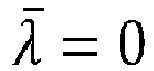
λ are given by- if the higher-layer parameter dmrs-Downlink-r16 in the DMRS-DownlinkConfig IE is provided


- otherwise by

- if the higher-layer parameter dmrs-Downlink-r16 in the DMRS-DownlinkConfig IE is provided
- The quantity n SCID ∈ {0,1} is given by the DM-RS sequence initialization field, if present, in the DCI associated with the PDSCH transmission if DCI format 1_1 or 1_2 in [4, TS 38.212] is used, otherwise n SCID = 0.
- As can be seen from comparing the above-reproduced sections of
5G NR Releases 5G NR Release 16 defines different scrambling codes for different CDM groups (which methodology can't be applied in5G NR Release 15 devices). More specifically, in5G NR Release 16, DMRS c init is dependent on the CDM group that eliminates the high PAPR when two CDM groups are used (i.e., above 2 layer). Therefore, the present invention applies to the gNB/distributed unit (DU) only, and is fully transparent to the radio unit (RU) and the user equipment (UE), and does not require any change in either the RU or the UE. - Although the example embodiments of the methods have been described in the present disclosure in the context of an O-RAN system, the present disclosure is equally applicable to any wireless system that supports
3GPP Release 15.
Claims (20)
- A method for reducing peak-to-average power ratio (PAPR) of a multi-layer precoder matrix (PM)-combined demodulation reference signal (DMRS) symbol in a 5G New Radio (NR) transmission involving a radio access network (RAN), the method comprising:
one of:a) performing, at a distributed unit (DU) of the RAN, a modified orthogonal cover code (M-OCC) method to reduce the PAPR of the multi-layer PM-combined DMRS, wherein the M-OCC method comprises;i. multiplying a PM with a specified multiplication factor in frequency domain to obtain a modified PM, andii. subsequently multiplying at least one of multiple downlink (DL) layers with the modified PM; orb) performing, at a distributed unit (DU) of the RAN, a modified cyclic delay diversity (M-CDD) method to reduce the PAPR of the multi-layer PM-combined DMRS, wherein the M-CCD method comprises;i. multiplying at least one of multiple frequency-domain downlink (DL) layers with a specified linear phase shift to obtain phase-shifted DL layers, andii. subsequently multiplying the phase-shifted DL layers with the PM. - The method according to claim 1, wherein the M-OCC method is performed for three DL layers comprising layer 0, layer 1 and layer 2.
- The method according to claim 2, wherein the specified multiplication factor is applied to layer 2.
- The method according to claim 3, wherein the value of b is one of -1 and 1.
- The method according to claim 4, wherein i) the value of b is -1 for a precoder resource group (PRG) length of 2 physical resource blocks (PRBs), and ii) the value of b is 1 for a PRG length of 4 PRBs.
- The method according to claim 3, wherein the layer 0 and the layer 1 are not multiplied by the specified multiplication factor.
- The method according to claim 1, wherein the M-OCC method is performed for four DL layers comprising layer 0, layer 1, layer 2, and layer 3.
- The method according to claim 7, wherein a specified multiplication factor is applied to layer 3.
- The method according to claim 8, wherein the specified multiplication factor is -1.
- The method according to claim 8, wherein the layer 0, the layer 1, and the layer 2 are not multiplied by the specified multiplication factor.
- The method according to claim 1, wherein the M-CCD method is performed for three DL layers comprising layer 0, layer 1 and layer 2.
- The method according to claim 11, wherein slope of the specified linear phase shift in frequency domain translates to a cyclic delay in time-domain.
- The method according to claim 12, wherein the cyclic delay "d" can range from 0 to the symbol length N-1, and wherein N represents the number of resource elements (REs).
- The method according to claim 11, wherein the layer-2 is multiplied with the specified linear phase shift.
- The method according to claim 14, wherein the layer-0 and the layer-1 are not multiplied by the specified linear phase shift.
- The method according to claim 15, wherein the specified phase shift is applied to a specified number of resource elements (REs) based on a precoder resource group (PRG) length.
- The method according to claim 11, wherein the M-CCD method is performed for four DL layers comprising layer 0, layer 1, layer 2, and layer 3.
- The method according to claim 17, wherein the layer-2 and the layer-3 are multiplied by the specified linear phase shift for all symbol physical resource blocks (PRBs).
- The method according to claim 17, wherein the layer-0 and the layer-1 are not multiplied by the specified linear phase shift.
- The method according to claim 19, wherein the specified phase shift is applied to a specified number of resource elements (REs) based on a precoder resource group (PRG) length.
Applications Claiming Priority (2)
| Application Number | Priority Date | Filing Date | Title |
|---|---|---|---|
| US202263355796P | 2022-06-27 | 2022-06-27 | |
| US18/338,425 US20230421423A1 (en) | 2022-06-27 | 2023-06-21 | Multi-Layer PAPR Reduction |
Publications (2)
| Publication Number | Publication Date |
|---|---|
| EP4300904A2 true EP4300904A2 (en) | 2024-01-03 |
| EP4300904A3 EP4300904A3 (en) | 2024-01-17 |
Family
ID=87003083
Family Applications (1)
| Application Number | Title | Priority Date | Filing Date |
|---|---|---|---|
| EP23181798.2A Pending EP4300904A3 (en) | 2022-06-27 | 2023-06-27 | Multi-layer papr reduction |
Country Status (2)
| Country | Link |
|---|---|
| US (1) | US20230421423A1 (en) |
| EP (1) | EP4300904A3 (en) |
Citations (1)
| Publication number | Priority date | Publication date | Assignee | Title |
|---|---|---|---|---|
| WO2020069455A1 (en) * | 2018-09-28 | 2020-04-02 | Intel Corporation | Peak-to-average power ratio (papr) reduction in reference signals |
Family Cites Families (8)
| Publication number | Priority date | Publication date | Assignee | Title |
|---|---|---|---|---|
| KR101789621B1 (en) * | 2010-01-19 | 2017-10-25 | 엘지전자 주식회사 | A method and a base station for transmitting uplink data, and a method and a user equipment for receiving uplink data |
| US11405138B2 (en) * | 2017-02-06 | 2022-08-02 | Telefonaktiebolaget Lm Ericsson (Publ) | Mixed space time and space frequency block coding |
| US11695507B2 (en) * | 2017-03-24 | 2023-07-04 | Samsung Electronics Co., Ltd. | Apparatus and method for in multiple access in wireless communication |
| WO2019039917A1 (en) * | 2017-08-24 | 2019-02-28 | Samsung Electronics Co., Ltd. | Dmrs port grouping method and apparatus for use in wireless cellular communication system |
| EP4429161B1 (en) * | 2018-10-10 | 2026-05-20 | Ericsson Telefon Ab L M | METHOD FOR REDUCING THE PEAK-TO-AVERAGE POWER OF DM-RS SIGNALS |
| US11184134B2 (en) * | 2018-12-06 | 2021-11-23 | Qualcomm Incorporated | Power imbalance solutions for multiple input multiple output transmissions |
| US11563615B2 (en) * | 2020-03-27 | 2023-01-24 | Qualcomm Incorporated | Iterative reference signal symbol reconstruction and channel estimation |
| CN116996184A (en) * | 2022-04-24 | 2023-11-03 | 华为技术有限公司 | A communication method and device |
-
2023
- 2023-06-21 US US18/338,425 patent/US20230421423A1/en active Pending
- 2023-06-27 EP EP23181798.2A patent/EP4300904A3/en active Pending
Patent Citations (1)
| Publication number | Priority date | Publication date | Assignee | Title |
|---|---|---|---|---|
| WO2020069455A1 (en) * | 2018-09-28 | 2020-04-02 | Intel Corporation | Peak-to-average power ratio (papr) reduction in reference signals |
Non-Patent Citations (4)
| Title |
|---|
| 3GPP TS 38.211, June 2020 (2020-06-01) |
| 3GPP TS 38.211, September 2018 (2018-09-01) |
| ERICSSON: "Benefits of resource specific DMRS mapping", vol. RAN WG1, no. Busan, Korea; 20180521 - 20180525, 20 May 2018 (2018-05-20), XP051441440, Retrieved from the Internet <URL:http://www.3gpp.org/ftp/Meetings%5F3GPP%5FSYNC/RAN1/Docs/> [retrieved on 20180520] * |
| ETSI TS 138 211, July 2020 (2020-07-01) |
Also Published As
| Publication number | Publication date |
|---|---|
| EP4300904A3 (en) | 2024-01-17 |
| US20230421423A1 (en) | 2023-12-28 |
Similar Documents
| Publication | Publication Date | Title |
|---|---|---|
| Michailow et al. | Bit error rate performance of generalized frequency division multiplexing | |
| US9356746B2 (en) | Transmission method, transmission device, receiving method, and receiving device | |
| US9154270B2 (en) | Method and apparatus for performing HARQ in a wireless communication system | |
| AU2014354845B2 (en) | System and method for radio frequency carrier aggregation | |
| EP3529957B1 (en) | Synthesis of near-constant modulus waveform for high frequency transmission | |
| US8797837B2 (en) | System and method for in-phase/quadrature multiplexing | |
| Araújo et al. | Analytical evaluation of nonlinear distortion effects on multicarrier signals | |
| US8891556B2 (en) | Signal for transmission in single-carrier communication system | |
| Kansal et al. | Multiuser massive MIMO-OFDM system incorporated with diverse transformation for 5G applications | |
| Kim et al. | A low-complex svd-based f-ofdm | |
| US8958489B2 (en) | Method of modulating signal for data communication and device thereof | |
| US20110116359A1 (en) | Methods and apparatus for interleaving in ofdm/ofdma systems | |
| Boudjelal et al. | Toward a common transceiver framework for 6G: Orthogonal coexistence and structural unification of DFT waveforms | |
| Sathiyapriya | Implementation and study of universal filtered multi carrier under carrier frequency offset for 5G | |
| Berggren et al. | Permutation polynomial interleaved DFT-s-OFDM | |
| CN101136897A (en) | Frequency Division Multiple Access Method in Time Domain Synchronous Orthogonal Frequency Division Multiplexing System | |
| US20230421423A1 (en) | Multi-Layer PAPR Reduction | |
| EP2251997A1 (en) | Wireless transmitter, wireless receiver, wireless communication system, and wireless transmission method | |
| US10491349B2 (en) | Methods and devices for multiple access transmission | |
| Reddy et al. | MIMO OTFS in 5G NR resource grid | |
| Thabet et al. | Synchronization error reduction using guard-band allocation for wireless communication systems | |
| Qin et al. | Low cubic metric Reed-Muller sequence design for pilot-less transmission | |
| Pitaval et al. | DFT-s-OFDM-based On-Off Keying for Low-Power Wake-Up Signal | |
| US20100303164A1 (en) | Block spreading for orthogonal frequency divsion multiple access systems | |
| Farhang et al. | Precoded GFDM system for self-interference mitigation |
Legal Events
| Date | Code | Title | Description |
|---|---|---|---|
| PUAI | Public reference made under article 153(3) epc to a published international application that has entered the european phase |
Free format text: ORIGINAL CODE: 0009012 |
|
| STAA | Information on the status of an ep patent application or granted ep patent |
Free format text: STATUS: REQUEST FOR EXAMINATION WAS MADE |
|
| PUAL | Search report despatched |
Free format text: ORIGINAL CODE: 0009013 |
|
| 17P | Request for examination filed |
Effective date: 20230627 |
|
| AK | Designated contracting states |
Kind code of ref document: A2 Designated state(s): AL AT BE BG CH CY CZ DE DK EE ES FI FR GB GR HR HU IE IS IT LI LT LU LV MC ME MK MT NL NO PL PT RO RS SE SI SK SM TR |
|
| AK | Designated contracting states |
Kind code of ref document: A3 Designated state(s): AL AT BE BG CH CY CZ DE DK EE ES FI FR GB GR HR HU IE IS IT LI LT LU LV MC ME MK MT NL NO PL PT RO RS SE SI SK SM TR |
|
| RIC1 | Information provided on ipc code assigned before grant |
Ipc: H04L 27/26 20060101AFI20231213BHEP |
|
| P01 | Opt-out of the competence of the unified patent court (upc) registered |
Effective date: 20240111 |
|
| STAA | Information on the status of an ep patent application or granted ep patent |
Free format text: STATUS: EXAMINATION IS IN PROGRESS |
|
| 17Q | First examination report despatched |
Effective date: 20260116 |